WO2012169009A1 - Electric vehicle and method for controlling electric vehicle - Google Patents
Electric vehicle and method for controlling electric vehicle Download PDFInfo
- Publication number
- WO2012169009A1 WO2012169009A1 PCT/JP2011/063029 JP2011063029W WO2012169009A1 WO 2012169009 A1 WO2012169009 A1 WO 2012169009A1 JP 2011063029 W JP2011063029 W JP 2011063029W WO 2012169009 A1 WO2012169009 A1 WO 2012169009A1
- Authority
- WO
- WIPO (PCT)
- Prior art keywords
- storage device
- power storage
- power
- upper limit
- limit value
- Prior art date
Links
Images


Classifications
-
- B—PERFORMING OPERATIONS; TRANSPORTING
- B60—VEHICLES IN GENERAL
- B60L—PROPULSION OF ELECTRICALLY-PROPELLED VEHICLES; SUPPLYING ELECTRIC POWER FOR AUXILIARY EQUIPMENT OF ELECTRICALLY-PROPELLED VEHICLES; ELECTRODYNAMIC BRAKE SYSTEMS FOR VEHICLES IN GENERAL; MAGNETIC SUSPENSION OR LEVITATION FOR VEHICLES; MONITORING OPERATING VARIABLES OF ELECTRICALLY-PROPELLED VEHICLES; ELECTRIC SAFETY DEVICES FOR ELECTRICALLY-PROPELLED VEHICLES
- B60L7/00—Electrodynamic brake systems for vehicles in general
- B60L7/10—Dynamic electric regenerative braking
- B60L7/14—Dynamic electric regenerative braking for vehicles propelled by ac motors
-
- B—PERFORMING OPERATIONS; TRANSPORTING
- B60—VEHICLES IN GENERAL
- B60L—PROPULSION OF ELECTRICALLY-PROPELLED VEHICLES; SUPPLYING ELECTRIC POWER FOR AUXILIARY EQUIPMENT OF ELECTRICALLY-PROPELLED VEHICLES; ELECTRODYNAMIC BRAKE SYSTEMS FOR VEHICLES IN GENERAL; MAGNETIC SUSPENSION OR LEVITATION FOR VEHICLES; MONITORING OPERATING VARIABLES OF ELECTRICALLY-PROPELLED VEHICLES; ELECTRIC SAFETY DEVICES FOR ELECTRICALLY-PROPELLED VEHICLES
- B60L1/00—Supplying electric power to auxiliary equipment of vehicles
-
- B—PERFORMING OPERATIONS; TRANSPORTING
- B60—VEHICLES IN GENERAL
- B60L—PROPULSION OF ELECTRICALLY-PROPELLED VEHICLES; SUPPLYING ELECTRIC POWER FOR AUXILIARY EQUIPMENT OF ELECTRICALLY-PROPELLED VEHICLES; ELECTRODYNAMIC BRAKE SYSTEMS FOR VEHICLES IN GENERAL; MAGNETIC SUSPENSION OR LEVITATION FOR VEHICLES; MONITORING OPERATING VARIABLES OF ELECTRICALLY-PROPELLED VEHICLES; ELECTRIC SAFETY DEVICES FOR ELECTRICALLY-PROPELLED VEHICLES
- B60L15/00—Methods, circuits, or devices for controlling the traction-motor speed of electrically-propelled vehicles
- B60L15/20—Methods, circuits, or devices for controlling the traction-motor speed of electrically-propelled vehicles for control of the vehicle or its driving motor to achieve a desired performance, e.g. speed, torque, programmed variation of speed
- B60L15/2009—Methods, circuits, or devices for controlling the traction-motor speed of electrically-propelled vehicles for control of the vehicle or its driving motor to achieve a desired performance, e.g. speed, torque, programmed variation of speed for braking
-
- B—PERFORMING OPERATIONS; TRANSPORTING
- B60—VEHICLES IN GENERAL
- B60L—PROPULSION OF ELECTRICALLY-PROPELLED VEHICLES; SUPPLYING ELECTRIC POWER FOR AUXILIARY EQUIPMENT OF ELECTRICALLY-PROPELLED VEHICLES; ELECTRODYNAMIC BRAKE SYSTEMS FOR VEHICLES IN GENERAL; MAGNETIC SUSPENSION OR LEVITATION FOR VEHICLES; MONITORING OPERATING VARIABLES OF ELECTRICALLY-PROPELLED VEHICLES; ELECTRIC SAFETY DEVICES FOR ELECTRICALLY-PROPELLED VEHICLES
- B60L50/00—Electric propulsion with power supplied within the vehicle
- B60L50/10—Electric propulsion with power supplied within the vehicle using propulsion power supplied by engine-driven generators, e.g. generators driven by combustion engines
- B60L50/16—Electric propulsion with power supplied within the vehicle using propulsion power supplied by engine-driven generators, e.g. generators driven by combustion engines with provision for separate direct mechanical propulsion
-
- B—PERFORMING OPERATIONS; TRANSPORTING
- B60—VEHICLES IN GENERAL
- B60L—PROPULSION OF ELECTRICALLY-PROPELLED VEHICLES; SUPPLYING ELECTRIC POWER FOR AUXILIARY EQUIPMENT OF ELECTRICALLY-PROPELLED VEHICLES; ELECTRODYNAMIC BRAKE SYSTEMS FOR VEHICLES IN GENERAL; MAGNETIC SUSPENSION OR LEVITATION FOR VEHICLES; MONITORING OPERATING VARIABLES OF ELECTRICALLY-PROPELLED VEHICLES; ELECTRIC SAFETY DEVICES FOR ELECTRICALLY-PROPELLED VEHICLES
- B60L50/00—Electric propulsion with power supplied within the vehicle
- B60L50/50—Electric propulsion with power supplied within the vehicle using propulsion power supplied by batteries or fuel cells
- B60L50/60—Electric propulsion with power supplied within the vehicle using propulsion power supplied by batteries or fuel cells using power supplied by batteries
- B60L50/61—Electric propulsion with power supplied within the vehicle using propulsion power supplied by batteries or fuel cells using power supplied by batteries by batteries charged by engine-driven generators, e.g. series hybrid electric vehicles
-
- B—PERFORMING OPERATIONS; TRANSPORTING
- B60—VEHICLES IN GENERAL
- B60L—PROPULSION OF ELECTRICALLY-PROPELLED VEHICLES; SUPPLYING ELECTRIC POWER FOR AUXILIARY EQUIPMENT OF ELECTRICALLY-PROPELLED VEHICLES; ELECTRODYNAMIC BRAKE SYSTEMS FOR VEHICLES IN GENERAL; MAGNETIC SUSPENSION OR LEVITATION FOR VEHICLES; MONITORING OPERATING VARIABLES OF ELECTRICALLY-PROPELLED VEHICLES; ELECTRIC SAFETY DEVICES FOR ELECTRICALLY-PROPELLED VEHICLES
- B60L53/00—Methods of charging batteries, specially adapted for electric vehicles; Charging stations or on-board charging equipment therefor; Exchange of energy storage elements in electric vehicles
- B60L53/10—Methods of charging batteries, specially adapted for electric vehicles; Charging stations or on-board charging equipment therefor; Exchange of energy storage elements in electric vehicles characterised by the energy transfer between the charging station and the vehicle
- B60L53/14—Conductive energy transfer
-
- B—PERFORMING OPERATIONS; TRANSPORTING
- B60—VEHICLES IN GENERAL
- B60L—PROPULSION OF ELECTRICALLY-PROPELLED VEHICLES; SUPPLYING ELECTRIC POWER FOR AUXILIARY EQUIPMENT OF ELECTRICALLY-PROPELLED VEHICLES; ELECTRODYNAMIC BRAKE SYSTEMS FOR VEHICLES IN GENERAL; MAGNETIC SUSPENSION OR LEVITATION FOR VEHICLES; MONITORING OPERATING VARIABLES OF ELECTRICALLY-PROPELLED VEHICLES; ELECTRIC SAFETY DEVICES FOR ELECTRICALLY-PROPELLED VEHICLES
- B60L58/00—Methods or circuit arrangements for monitoring or controlling batteries or fuel cells, specially adapted for electric vehicles
- B60L58/10—Methods or circuit arrangements for monitoring or controlling batteries or fuel cells, specially adapted for electric vehicles for monitoring or controlling batteries
- B60L58/12—Methods or circuit arrangements for monitoring or controlling batteries or fuel cells, specially adapted for electric vehicles for monitoring or controlling batteries responding to state of charge [SoC]
- B60L58/13—Maintaining the SoC within a determined range
-
- B—PERFORMING OPERATIONS; TRANSPORTING
- B60—VEHICLES IN GENERAL
- B60L—PROPULSION OF ELECTRICALLY-PROPELLED VEHICLES; SUPPLYING ELECTRIC POWER FOR AUXILIARY EQUIPMENT OF ELECTRICALLY-PROPELLED VEHICLES; ELECTRODYNAMIC BRAKE SYSTEMS FOR VEHICLES IN GENERAL; MAGNETIC SUSPENSION OR LEVITATION FOR VEHICLES; MONITORING OPERATING VARIABLES OF ELECTRICALLY-PROPELLED VEHICLES; ELECTRIC SAFETY DEVICES FOR ELECTRICALLY-PROPELLED VEHICLES
- B60L58/00—Methods or circuit arrangements for monitoring or controlling batteries or fuel cells, specially adapted for electric vehicles
- B60L58/10—Methods or circuit arrangements for monitoring or controlling batteries or fuel cells, specially adapted for electric vehicles for monitoring or controlling batteries
- B60L58/12—Methods or circuit arrangements for monitoring or controlling batteries or fuel cells, specially adapted for electric vehicles for monitoring or controlling batteries responding to state of charge [SoC]
- B60L58/15—Preventing overcharging
-
- B—PERFORMING OPERATIONS; TRANSPORTING
- B60—VEHICLES IN GENERAL
- B60L—PROPULSION OF ELECTRICALLY-PROPELLED VEHICLES; SUPPLYING ELECTRIC POWER FOR AUXILIARY EQUIPMENT OF ELECTRICALLY-PROPELLED VEHICLES; ELECTRODYNAMIC BRAKE SYSTEMS FOR VEHICLES IN GENERAL; MAGNETIC SUSPENSION OR LEVITATION FOR VEHICLES; MONITORING OPERATING VARIABLES OF ELECTRICALLY-PROPELLED VEHICLES; ELECTRIC SAFETY DEVICES FOR ELECTRICALLY-PROPELLED VEHICLES
- B60L58/00—Methods or circuit arrangements for monitoring or controlling batteries or fuel cells, specially adapted for electric vehicles
- B60L58/10—Methods or circuit arrangements for monitoring or controlling batteries or fuel cells, specially adapted for electric vehicles for monitoring or controlling batteries
- B60L58/16—Methods or circuit arrangements for monitoring or controlling batteries or fuel cells, specially adapted for electric vehicles for monitoring or controlling batteries responding to battery ageing, e.g. to the number of charging cycles or the state of health [SoH]
-
- B—PERFORMING OPERATIONS; TRANSPORTING
- B60—VEHICLES IN GENERAL
- B60L—PROPULSION OF ELECTRICALLY-PROPELLED VEHICLES; SUPPLYING ELECTRIC POWER FOR AUXILIARY EQUIPMENT OF ELECTRICALLY-PROPELLED VEHICLES; ELECTRODYNAMIC BRAKE SYSTEMS FOR VEHICLES IN GENERAL; MAGNETIC SUSPENSION OR LEVITATION FOR VEHICLES; MONITORING OPERATING VARIABLES OF ELECTRICALLY-PROPELLED VEHICLES; ELECTRIC SAFETY DEVICES FOR ELECTRICALLY-PROPELLED VEHICLES
- B60L7/00—Electrodynamic brake systems for vehicles in general
- B60L7/10—Dynamic electric regenerative braking
- B60L7/16—Dynamic electric regenerative braking for vehicles comprising converters between the power source and the motor
-
- H—ELECTRICITY
- H02—GENERATION; CONVERSION OR DISTRIBUTION OF ELECTRIC POWER
- H02J—CIRCUIT ARRANGEMENTS OR SYSTEMS FOR SUPPLYING OR DISTRIBUTING ELECTRIC POWER; SYSTEMS FOR STORING ELECTRIC ENERGY
- H02J5/00—Circuit arrangements for transfer of electric power between ac networks and dc networks
-
- H—ELECTRICITY
- H02—GENERATION; CONVERSION OR DISTRIBUTION OF ELECTRIC POWER
- H02J—CIRCUIT ARRANGEMENTS OR SYSTEMS FOR SUPPLYING OR DISTRIBUTING ELECTRIC POWER; SYSTEMS FOR STORING ELECTRIC ENERGY
- H02J7/00—Circuit arrangements for charging or depolarising batteries or for supplying loads from batteries
- H02J7/007—Regulation of charging or discharging current or voltage
- H02J7/00712—Regulation of charging or discharging current or voltage the cycle being controlled or terminated in response to electric parameters
- H02J7/007182—Regulation of charging or discharging current or voltage the cycle being controlled or terminated in response to electric parameters in response to battery voltage
-
- H—ELECTRICITY
- H02—GENERATION; CONVERSION OR DISTRIBUTION OF ELECTRIC POWER
- H02J—CIRCUIT ARRANGEMENTS OR SYSTEMS FOR SUPPLYING OR DISTRIBUTING ELECTRIC POWER; SYSTEMS FOR STORING ELECTRIC ENERGY
- H02J7/00—Circuit arrangements for charging or depolarising batteries or for supplying loads from batteries
- H02J7/02—Circuit arrangements for charging or depolarising batteries or for supplying loads from batteries for charging batteries from ac mains by converters
- H02J7/04—Regulation of charging current or voltage
-
- H—ELECTRICITY
- H02—GENERATION; CONVERSION OR DISTRIBUTION OF ELECTRIC POWER
- H02J—CIRCUIT ARRANGEMENTS OR SYSTEMS FOR SUPPLYING OR DISTRIBUTING ELECTRIC POWER; SYSTEMS FOR STORING ELECTRIC ENERGY
- H02J7/00—Circuit arrangements for charging or depolarising batteries or for supplying loads from batteries
- H02J7/14—Circuit arrangements for charging or depolarising batteries or for supplying loads from batteries for charging batteries from dynamo-electric generators driven at varying speed, e.g. on vehicle
-
- Y—GENERAL TAGGING OF NEW TECHNOLOGICAL DEVELOPMENTS; GENERAL TAGGING OF CROSS-SECTIONAL TECHNOLOGIES SPANNING OVER SEVERAL SECTIONS OF THE IPC; TECHNICAL SUBJECTS COVERED BY FORMER USPC CROSS-REFERENCE ART COLLECTIONS [XRACs] AND DIGESTS
- Y02—TECHNOLOGIES OR APPLICATIONS FOR MITIGATION OR ADAPTATION AGAINST CLIMATE CHANGE
- Y02T—CLIMATE CHANGE MITIGATION TECHNOLOGIES RELATED TO TRANSPORTATION
- Y02T10/00—Road transport of goods or passengers
- Y02T10/60—Other road transportation technologies with climate change mitigation effect
- Y02T10/62—Hybrid vehicles
-
- Y—GENERAL TAGGING OF NEW TECHNOLOGICAL DEVELOPMENTS; GENERAL TAGGING OF CROSS-SECTIONAL TECHNOLOGIES SPANNING OVER SEVERAL SECTIONS OF THE IPC; TECHNICAL SUBJECTS COVERED BY FORMER USPC CROSS-REFERENCE ART COLLECTIONS [XRACs] AND DIGESTS
- Y02—TECHNOLOGIES OR APPLICATIONS FOR MITIGATION OR ADAPTATION AGAINST CLIMATE CHANGE
- Y02T—CLIMATE CHANGE MITIGATION TECHNOLOGIES RELATED TO TRANSPORTATION
- Y02T10/00—Road transport of goods or passengers
- Y02T10/60—Other road transportation technologies with climate change mitigation effect
- Y02T10/64—Electric machine technologies in electromobility
-
- Y—GENERAL TAGGING OF NEW TECHNOLOGICAL DEVELOPMENTS; GENERAL TAGGING OF CROSS-SECTIONAL TECHNOLOGIES SPANNING OVER SEVERAL SECTIONS OF THE IPC; TECHNICAL SUBJECTS COVERED BY FORMER USPC CROSS-REFERENCE ART COLLECTIONS [XRACs] AND DIGESTS
- Y02—TECHNOLOGIES OR APPLICATIONS FOR MITIGATION OR ADAPTATION AGAINST CLIMATE CHANGE
- Y02T—CLIMATE CHANGE MITIGATION TECHNOLOGIES RELATED TO TRANSPORTATION
- Y02T10/00—Road transport of goods or passengers
- Y02T10/60—Other road transportation technologies with climate change mitigation effect
- Y02T10/70—Energy storage systems for electromobility, e.g. batteries
-
- Y—GENERAL TAGGING OF NEW TECHNOLOGICAL DEVELOPMENTS; GENERAL TAGGING OF CROSS-SECTIONAL TECHNOLOGIES SPANNING OVER SEVERAL SECTIONS OF THE IPC; TECHNICAL SUBJECTS COVERED BY FORMER USPC CROSS-REFERENCE ART COLLECTIONS [XRACs] AND DIGESTS
- Y02—TECHNOLOGIES OR APPLICATIONS FOR MITIGATION OR ADAPTATION AGAINST CLIMATE CHANGE
- Y02T—CLIMATE CHANGE MITIGATION TECHNOLOGIES RELATED TO TRANSPORTATION
- Y02T10/00—Road transport of goods or passengers
- Y02T10/60—Other road transportation technologies with climate change mitigation effect
- Y02T10/7072—Electromobility specific charging systems or methods for batteries, ultracapacitors, supercapacitors or double-layer capacitors
-
- Y—GENERAL TAGGING OF NEW TECHNOLOGICAL DEVELOPMENTS; GENERAL TAGGING OF CROSS-SECTIONAL TECHNOLOGIES SPANNING OVER SEVERAL SECTIONS OF THE IPC; TECHNICAL SUBJECTS COVERED BY FORMER USPC CROSS-REFERENCE ART COLLECTIONS [XRACs] AND DIGESTS
- Y02—TECHNOLOGIES OR APPLICATIONS FOR MITIGATION OR ADAPTATION AGAINST CLIMATE CHANGE
- Y02T—CLIMATE CHANGE MITIGATION TECHNOLOGIES RELATED TO TRANSPORTATION
- Y02T10/00—Road transport of goods or passengers
- Y02T10/60—Other road transportation technologies with climate change mitigation effect
- Y02T10/72—Electric energy management in electromobility
-
- Y—GENERAL TAGGING OF NEW TECHNOLOGICAL DEVELOPMENTS; GENERAL TAGGING OF CROSS-SECTIONAL TECHNOLOGIES SPANNING OVER SEVERAL SECTIONS OF THE IPC; TECHNICAL SUBJECTS COVERED BY FORMER USPC CROSS-REFERENCE ART COLLECTIONS [XRACs] AND DIGESTS
- Y02—TECHNOLOGIES OR APPLICATIONS FOR MITIGATION OR ADAPTATION AGAINST CLIMATE CHANGE
- Y02T—CLIMATE CHANGE MITIGATION TECHNOLOGIES RELATED TO TRANSPORTATION
- Y02T90/00—Enabling technologies or technologies with a potential or indirect contribution to GHG emissions mitigation
- Y02T90/10—Technologies relating to charging of electric vehicles
- Y02T90/14—Plug-in electric vehicles
Abstract
This electric vehicle is provided with: a charging control unit which sets the fully charged state of a power storage device, which is mounted on the vehicle, so as to have a margin with respect to the full charge capacity of the power storage device, and which sets an upper limit on the charging power permitted in the power storage device according to the upper limit on a charged state value of the power storage device, which is specified in association with the fully charged state; and a travel control unit which keeps the charging power of the power storage device below the upper limit on the charging power. The charging control unit variably sets the fully charged state according to the degree of degradation of the power storage device, in such a manner that the margin becomes smaller the larger the degree of degradation of the power storage device. When regenerative power generated by an electric motor during regenerative braking of the vehicle exceeds the upper limit on the charging power, the travel control unit switches between a first control for regenerating the excess portion of regenerative power over the upper limit on the charging power in the power storage device, and a second control for consuming the excess portion of the regenerative power using an auxiliary load, according to the degree of decrease in the margin.
Description
この発明は、電動車両および電動車両の制御方法に関し、より特定的には、電動車両に搭載された蓄電装置の充電制御に関する。
The present invention relates to an electric vehicle and a method for controlling the electric vehicle, and more particularly to charge control of a power storage device mounted on the electric vehicle.
電動機によって車両駆動力を発生可能に構成された、電気自動車、ハイブリッド自動車および燃料電池自動車等の電動車両では、当該電動機を駆動するための電力を蓄積する蓄電装置が搭載されている。このような電動車両では、発進時や加速時などに蓄電装置から電動機に電力を供給して車両駆動力を発生する一方で、降坂走行時や減速時などに電動機の回生制動により発生した電力を蓄電装置に供給する。したがって、車両走行中には蓄電装置の放電および充電が繰り返し実行されるため、車両走行中の蓄電装置の充電状態(SOC:State of Charge;以下、単に「SOC」とも称す)の管理制御が必要となる。なお、SOCとは、満充電容量に対する現在の残容量の比率を示したものである。一般的には、SOCが所定の制御範囲から外れることがないように、蓄電装置の充放電が制御される。
In an electric vehicle such as an electric vehicle, a hybrid vehicle, and a fuel cell vehicle that can generate a vehicle driving force by an electric motor, a power storage device that stores electric power for driving the electric motor is mounted. In such an electric vehicle, the electric power generated from the power storage device is supplied to the electric motor from the power storage device when starting or accelerating to generate vehicle driving force, while the electric power generated by regenerative braking of the electric motor during downhill driving or deceleration. Is supplied to the power storage device. Therefore, since the discharging and charging of the power storage device are repeatedly executed while the vehicle is traveling, it is necessary to manage and control the state of charge (SOC: State of Charge; hereinafter also referred to simply as “SOC”) of the power storage device while the vehicle is traveling. It becomes. The SOC indicates the ratio of the current remaining capacity to the full charge capacity. Generally, charging / discharging of the power storage device is controlled so that the SOC does not deviate from a predetermined control range.
このような電動車両のSOC制御の一態様として、特開2003-134602号公報(特許文献1)には、駆動用電動機の回生運転時に発生した回生エネルギを電気エネルギとしてバッテリに蓄積するように構成されたハイブリッド車両の回生エネルギ制御装置が開示される。特開2003-134602号公報(特許文献1)によれば、回生エネルギをバッテリが回収できない場合には、発電用電動機を制御して、バッテリが回収しきれない回生エネルギ量に見合った大きさのd軸電流を発電用電動機に流すことにより、発電用電動機の熱損失として余剰の電気エネルギを回収する。
As one aspect of the SOC control of such an electric vehicle, Japanese Patent Laid-Open No. 2003-134602 (Patent Document 1) is configured to store regenerative energy generated during regenerative operation of a driving motor as electric energy in a battery. A regenerative energy control device for a hybrid vehicle is disclosed. According to Japanese Patent Laying-Open No. 2003-134602 (Patent Document 1), when the battery cannot recover the regenerative energy, the generator motor is controlled to have a size corresponding to the amount of regenerative energy that cannot be recovered by the battery. By causing the d-axis current to flow through the generator motor, surplus electrical energy is recovered as heat loss of the generator motor.
また特開2009-196404号公報(特許文献2)には、電動機の回生制動により発生する電力がバッテリの充電許可電力を超えてしまう場合には、余剰電力を空調装置で消費するように構成されたハイブリッド制御装置が開示される。
Japanese Patent Laid-Open No. 2009-196404 (Patent Document 2) is configured to consume surplus power by the air conditioner when the power generated by the regenerative braking of the motor exceeds the charge permission power of the battery. A hybrid controller is disclosed.
上記の特許文献1および2では、電動機が回生制動により発生した電力を車載蓄電装置が回収できない場合であっても、余剰電力を発電用電動機や空調装置で消費させることによって所望の制動力を確保する。
In Patent Documents 1 and 2 described above, even when the electric power generated by the motor due to regenerative braking cannot be recovered by the in-vehicle power storage device, a desired braking force is ensured by consuming surplus power with the generator motor or the air conditioner. To do.
ここで、蓄電装置として代表的に使用される二次電池の性能は、劣化の進行に応じて低下することが知られている。たとえば二次電池の満充電容量は、劣化の進行に応じて低下する。したがって、このような性能の劣化を十分に反映して電動機を回生制御しなければ、蓄電装置の性能劣化時(満充電容量の低下時)に、所望の制動力を確保できず、制動時のフィーリングを悪化させる虞がある。
Here, it is known that the performance of a secondary battery typically used as a power storage device decreases with the progress of deterioration. For example, the full charge capacity of the secondary battery decreases as the deterioration progresses. Therefore, if the electric motor is not regeneratively controlled to sufficiently reflect such performance deterioration, the desired braking force cannot be secured when the power storage device performance deteriorates (when the full charge capacity decreases), and There is a risk of worsening the feeling.
また、蓄電装置の使用年数が長くなるにつれて満充電容量が低下することにより、二次電池に蓄えられた電力によって電動車両が走行可能な距離(以下、電動車両の航続距離ともいう)が短くなる可能性がある。したがって、蓄電装置のSOCの制御にも、蓄電装置の劣化を反映させる必要がある。
Further, the full charge capacity decreases as the years of use of the power storage device become longer, thereby shortening the distance that the electric vehicle can travel with the electric power stored in the secondary battery (hereinafter also referred to as the cruising distance of the electric vehicle). there is a possibility. Therefore, it is necessary to reflect the deterioration of the power storage device also in the control of the SOC of the power storage device.
それゆえ、この発明は、かかる課題を解決するためになされたものであり、その目的は、制動時のフィーリングを損なうことがないように、車載蓄電装置の劣化を反映して電動機を回生制御することである。
Therefore, the present invention has been made to solve such a problem, and its purpose is to regeneratively control the motor reflecting the deterioration of the in-vehicle power storage device so as not to impair the feeling during braking. It is to be.
この発明のある局面に従えば、電動車両は、充放電可能な蓄電装置と、蓄電装置から電力の供給を受けて車両駆動力を発生するとともに、車両の回生制動時に発電した電力を蓄電装置に回生するように構成された電動機と、補機負荷と、蓄電装置の満充電容量に対してマージンを有するように蓄電装置の満充電状態を設定するとともに、満充電状態に対応付けて規定された蓄電装置の充電状態値の上限値に応じて、蓄電装置において許容される充電電力上限値を設定する充電制御部と、充電電力上限値の範囲内で蓄電装置の充電電力を制御する走行制御部とを備える。充電制御部は、蓄電装置の劣化度合いが大きいほどマージンが小さくなるように、蓄電装置の劣化度合いに応じて満充電状態を可変に設定する。走行制御部は、車両の回生制動時に電動機が発電した電力が充電電力上限値を超えるときには、マージンの低下度合いに応じて、充電電力上限値からの超過分を蓄電装置に回生するための第1の制御と、充電電力上限値からの超過分を補機負荷を用いて消費するための第2の制御とを切換える。
According to an aspect of the present invention, an electrically powered vehicle generates a vehicle driving force by receiving a chargeable / dischargeable power storage device and power supplied from the power storage device, and generates power generated during regenerative braking of the vehicle to the power storage device. The full charge state of the power storage device is set so as to have a margin with respect to the electric motor configured to regenerate, the auxiliary load, and the full charge capacity of the power storage device, and is defined in association with the full charge state A charge control unit that sets a charging power upper limit value that is allowed in the power storage device in accordance with an upper limit value of the charging state value of the power storage device, and a travel control unit that controls the charging power of the power storage device within the range of the charging power upper limit value With. The charge control unit variably sets the fully charged state according to the degree of deterioration of the power storage device so that the margin decreases as the degree of deterioration of the power storage device increases. When the electric power generated by the motor during the regenerative braking of the vehicle exceeds the charging power upper limit value, the travel control unit regenerates the excess from the charging power upper limit value to the power storage device in accordance with the margin reduction degree. And the second control for consuming the excess from the charging power upper limit value using the auxiliary load.
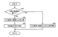
好ましくは、充電制御部は、予め定められた基準容量を満充電状態として充電状態値の上限値を設定するとともに、満充電容量が基準容量に達すると、満充電状態を基準容量から満充電容量に変更して充電状態値の上限値を設定する。走行制御部は、満充電容量が基準容量まで低下するまでの間は、第1の制御を実行する一方で、満充電容量が基準容量まで低下した後は、第2の制御を実行する。
Preferably, the charge control unit sets a predetermined reference capacity as a fully charged state and sets an upper limit value of the charged state value. When the full charge capacity reaches the reference capacity, the full charge state is changed from the reference capacity to the full charge capacity. To set the upper limit of the charge state value. The travel control unit executes the first control until the full charge capacity is reduced to the reference capacity, and executes the second control after the full charge capacity is reduced to the reference capacity.
好ましくは、充電制御部は、満充電容量が基準容量まで低下するまでの間は、蓄電装置の劣化度合いが大きいほど高い値となるように、充電状態値の上限値を可変に設定し、満充電容量が基準容量まで低下した後は、充電状態値の上限値を満充電状態に対応付けて規定される所定値に維持する。走行制御部は、充電状態値の上限値が所定値に達するまでの間は、第1の制御を実行する一方で、充電状態値の上限値が所定値に達した後は、第2の制御を実行する。
Preferably, the charge control unit variably sets the upper limit value of the charge state value so that the higher the deterioration degree of the power storage device, the higher the value until the full charge capacity is reduced to the reference capacity. After the charge capacity decreases to the reference capacity, the upper limit value of the charge state value is maintained at a predetermined value defined in association with the fully charged state. The travel control unit executes the first control until the upper limit value of the state of charge reaches a predetermined value, while the second control is performed after the upper limit value of the state of charge reaches the predetermined value. Execute.
この発明の別の局面に従えば、電動車両の制御方法であって、電動車両は、充放電可能な蓄電装置と、蓄電装置から電力の供給を受けて車両駆動力を発生するとともに、電動車両の回生制動時に発電した電力を蓄電装置に回生するように構成された電動機と、補機負荷とを含む。制御方法は、蓄電装置の満充電容量に対してマージンを有するように蓄電装置の満充電状態を設定するとともに、満充電状態に対応付けて規定された蓄電装置の充電状態値の上限値に応じて、蓄電装置において許容される充電電力上限値を設定するステップと、充電電力上限値の範囲内で蓄電装置の充電電力を制御するステップとを備える。充電電力上限値を設定するステップは、蓄電装置の劣化度合いが大きいほどマージンが小さくなるように、蓄電装置の劣化度合いに応じて満充電状態を可変に設定する。充電電力を制御するステップは、電動車両の回生制動時に電動機が発電した電力が充電電力上限値を超えるときには、マージンの低下度合いに応じて、充電電力上限値からの超過分を蓄電装置に回生するための第1の制御と、充電電力上限値からの超過分を補機負荷を用いて消費するための第2の制御とを切換える。
According to another aspect of the present invention, there is provided a control method for an electric vehicle, wherein the electric vehicle is a chargeable / dischargeable power storage device, and receives electric power from the power storage device to generate a vehicle driving force. An electric motor configured to regenerate electric power generated during regenerative braking to the power storage device, and an auxiliary load. The control method sets the full charge state of the power storage device to have a margin with respect to the full charge capacity of the power storage device, and responds to the upper limit value of the charge state value of the power storage device defined in association with the full charge state. Then, a step of setting a charging power upper limit value allowed in the power storage device and a step of controlling the charging power of the power storage device within the range of the charging power upper limit value are provided. In the step of setting the charging power upper limit value, the fully charged state is variably set according to the degree of deterioration of the power storage device so that the margin decreases as the degree of deterioration of the power storage device increases. In the step of controlling the charging power, when the electric power generated by the motor at the time of regenerative braking of the electric vehicle exceeds the charging power upper limit value, the excess from the charging power upper limit value is regenerated to the power storage device according to the margin reduction degree. The first control for switching and the second control for consuming the excess from the charging power upper limit value using the auxiliary load are switched.
この発明によれば、車載蓄電装置の劣化度合いを反映した蓄電装置の充電制御および電動機の回生制御を行なうことによって、電動車両の航続距離を確保しつつ、制動時のフィーリングの悪化を防止することができる。
According to the present invention, the charging control of the power storage device and the regeneration control of the electric motor reflecting the degree of deterioration of the in-vehicle power storage device are performed, thereby ensuring the cruising distance of the electric vehicle and preventing the deterioration of the feeling during braking. be able to.
以下、本発明の実施の形態について図面を参照しながら詳細に説明する。なお、図中同一または相当部分には同一符号を付してその説明が繰返さない。
Hereinafter, embodiments of the present invention will be described in detail with reference to the drawings. In the drawings, the same or corresponding parts are denoted by the same reference numerals and description thereof will not be repeated.
図1は、本発明の実施の形態による電動車両の代表例として示されるハイブリッド車両5の概略構成図である。
FIG. 1 is a schematic configuration diagram of a hybrid vehicle 5 shown as a representative example of an electric vehicle according to an embodiment of the present invention.
図1を参照して、ハイブリッド車両5は、エンジン(内燃機関)18とモータジェネレータMG1,MG2とを搭載する。さらに、ハイブリッド車両5は、モータジェネレータMG1,MG2との間で電力を入出力可能な蓄電装置10を搭載する。
Referring to FIG. 1, hybrid vehicle 5 includes an engine (internal combustion engine) 18 and motor generators MG1, MG2. Furthermore, hybrid vehicle 5 is equipped with power storage device 10 capable of inputting and outputting electric power between motor generators MG1 and MG2.
蓄電装置10は、再放電可能な電力貯蔵要素であり、代表的には、リチウムイオン電池やニッケル水素電池などの二次電池が適用される。あるいは、電気二重層キャパシタなどの電池以外の電力貯蔵要素によって、蓄電装置10を構成してもよい。図1には、ハイブリッド車両5のうちの蓄電装置10の充放電制御に関するシステム構成が記載されている。
The power storage device 10 is a re-dischargeable power storage element, and typically, a secondary battery such as a lithium ion battery or a nickel metal hydride battery is applied. Or you may comprise the electrical storage apparatus 10 by electric power storage elements other than batteries, such as an electric double layer capacitor. FIG. 1 shows a system configuration related to charge / discharge control of the power storage device 10 in the hybrid vehicle 5.
監視ユニット11は、蓄電装置10に設けられた温度センサ12、電圧センサ13および電流センサ14の出力に基づいて、蓄電装置10の「状態値」を検出する。すなわち、「状態値」は、蓄電装置10の温度Tb、電圧Vbおよび電流Ibを含む。上述のように、蓄電装置10として代表的に二次電池が用いられるため、蓄電装置10の温度Tb、電圧Vbおよび電流Ibについて、以下では、電池温度Tb、電池電圧Vbおよび電池電流Ibとも称する。また、電池温度Tb、電池電圧Vbおよび電池電流Ibを包括的に「電池データ」とも総称する。
The monitoring unit 11 detects the “state value” of the power storage device 10 based on the outputs of the temperature sensor 12, the voltage sensor 13 and the current sensor 14 provided in the power storage device 10. That is, “state value” includes temperature Tb, voltage Vb, and current Ib of power storage device 10. As described above, since a secondary battery is typically used as power storage device 10, temperature Tb, voltage Vb, and current Ib of power storage device 10 are hereinafter also referred to as battery temperature Tb, battery voltage Vb, and battery current Ib. . In addition, the battery temperature Tb, the battery voltage Vb, and the battery current Ib are collectively referred to as “battery data”.
なお、温度センサ12、電圧センサ13および電流センサ14については、蓄電装置10に設けられる温度センサ、電圧センサおよび電流センサのそれぞれを包括的に示すものである。すなわち、実際には、温度センサ12、電圧センサ13および電流センサ14の少なくとも一部については、複数個設けられることが一般的である点について確認的に記載する。
Note that the temperature sensor 12, the voltage sensor 13, and the current sensor 14 collectively indicate the temperature sensor, the voltage sensor, and the current sensor provided in the power storage device 10. That is, in practice, at least a part of the temperature sensor 12, the voltage sensor 13, and the current sensor 14 will be described in detail in terms of being generally provided.
エンジン18、モータジェネレータMG1およびMG2は、動力分割機構22を介して機械的に連結される。
Engine 18 and motor generators MG1 and MG2 are mechanically coupled via power split mechanism 22.
図2を参照して、動力分割機構22についてさらに説明する。動力分割機構22は、サンギヤ202と、ピニオンギヤ204と、キャリア206と、リングギヤ208とを含む遊星歯車によって構成される。
The power split mechanism 22 will be further described with reference to FIG. The power split mechanism 22 is constituted by a planetary gear including a sun gear 202, a pinion gear 204, a carrier 206, and a ring gear 208.
ピニオンギヤ204は、サンギヤ202およびリングギヤ208と係合する。キャリア206は、ピニオンギヤ204が自転可能なように支持する。サンギヤ202は、モータジェネレータMG1の回転軸に連結される。キャリア206は、エンジン18のクランクシャフトに連結される。リングギヤ208は、モータジェネレータMG2の回転軸および減速軸95に連結される。
The pinion gear 204 engages with the sun gear 202 and the ring gear 208. The carrier 206 supports the pinion gear 204 so that it can rotate. Sun gear 202 is coupled to the rotation shaft of motor generator MG1. The carrier 206 is connected to the crankshaft of the engine 18. Ring gear 208 is connected to the rotation shaft and reduction shaft 95 of motor generator MG2.
エンジン18、モータジェネレータMG1およびモータジェネレータMG2が、遊星歯車からなる動力分割機構22を介して連結されることで、エンジン18、モータジェネレータMG1およびモータジェネレータMG2の回転速度は、図3に示すように、共線図において直線で結ばれる関係になる。
The engine 18, the motor generator MG1 and the motor generator MG2 are connected via a power split mechanism 22 made of planetary gears, so that the rotational speeds of the engine 18, motor generator MG1 and motor generator MG2 are as shown in FIG. In the collinear diagram, the relationship is a straight line.
この結果、ハイブリッド車両5の走行時において、動力分割機構22は、エンジン18の作動によって発生する駆動力を二分割し、その一方をモータジェネレータMG1側へ配分するとともに、残部をモータジェネレータMG2へ配分する。動力分割機構22からモータジェネレータMG1側へ配分された駆動力は、発電動作に用いられる。一方、モータジェネレータMG2側へ配分された駆動力は、モータジェネレータMG2で発生した駆動力と合成されて、駆動輪24Fの駆動に使用される。
As a result, when the hybrid vehicle 5 is traveling, the power split mechanism 22 divides the driving force generated by the operation of the engine 18 into two parts, and distributes one of them to the motor generator MG1 side and the remaining part to the motor generator MG2. To do. The driving force distributed from power split mechanism 22 to motor generator MG1 side is used for the power generation operation. On the other hand, the driving force distributed to the motor generator MG2 side is combined with the driving force generated by the motor generator MG2 and used to drive the drive wheels 24F.
このように、ハイブリッド車両5の走行状況に応じて、動力分割機構22を介して上記3者の間で駆動力の分配および結合が行なわれ、その結果として、駆動輪24Fが駆動される。また、ハイブリッド車両5の走行中において、蓄電装置10は、エンジン18の出力を源とした、モータジェネレータMG1の発電電力により充電可能である。
Thus, according to the traveling state of the hybrid vehicle 5, the driving force is distributed and combined among the three parties via the power split mechanism 22, and as a result, the driving wheel 24F is driven. Further, while the hybrid vehicle 5 is traveling, the power storage device 10 can be charged by the generated power of the motor generator MG1 using the output of the engine 18 as a source.
再び図1を参照して、ハイブリッド車両5は、電力制御ユニット15をさらに備える。電力制御ユニット15は、モータジェネレータMG1およびモータジェネレータMG2と、蓄電装置10との間で双方向に電力変換するように構成される。電力制御ユニット15は、コンバータ(CONV)6と、モータジェネレータMG1およびMG2にそれぞれ対応付けられた第1インバータ(INV1)8-1および第2インバータ(INV2)8-2とを含む。
Referring to FIG. 1 again, the hybrid vehicle 5 further includes a power control unit 15. Power control unit 15 is configured to bi-directionally convert power between motor generator MG1 and motor generator MG2 and power storage device 10. Power control unit 15 includes a converter (CONV) 6, and a first inverter (INV1) 8-1 and a second inverter (INV2) 8-2 associated with motor generators MG1 and MG2, respectively.
コンバータ(CONV)6は、蓄電装置10と、インバータ8-1,8-2の直流リンク電圧を伝達する正母線MPLとの間で、双方向の直流電圧変換を実行するように構成される。すなわち、蓄電装置10の入出力電圧と、正母線MPLおよび負母線MNL間の直流電圧とは、双方向に昇圧または降圧される。コンバータ6における昇降圧動作は、制御装置30からのスイッチング指令PWCに従ってそれぞれ制御される。また、正母線MPLおよび負母線MNLの間には、平滑コンデンサCが接続される。そして、正母線MPLおよび負母線MNL間の直流電圧Vhは、電圧センサ16によって検知される。
Converter (CONV) 6 is configured to perform bidirectional DC voltage conversion between power storage device 10 and positive bus MPL that transmits the DC link voltage of inverters 8-1, 8-2. That is, the input / output voltage of power storage device 10 and the DC voltage between positive bus MPL and negative bus MNL are boosted or lowered in both directions. The step-up / step-down operation in converter 6 is controlled according to switching command PWC from control device 30. A smoothing capacitor C is connected between the positive bus MPL and the negative bus MNL. The DC voltage Vh between the positive bus MPL and the negative bus MNL is detected by the voltage sensor 16.
第1インバータ8-1および第2インバータ8-2は、正母線MPLおよび負母線MNLの直流電力と、モータジェネレータMG1およびMG2に入出力される交流電力との間の双方向の電力変換を実行する。主として、第1インバータ8-1は、制御装置30からのスイッチング指令PWM1に応じて、エンジン18の出力によってモータジェネレータMG1が発生する交流電力を直流電力に変換し、正母線MPLおよび負母線MNLへ供給する。これにより、車両走行中にも、エンジン18の出力によって蓄電装置10を能動的に充電できる。
First inverter 8-1 and second inverter 8-2 execute bidirectional power conversion between DC power of positive bus MPL and negative bus MNL and AC power input / output to / from motor generators MG1 and MG2. To do. Mainly, first inverter 8-1 converts AC power generated by motor generator MG 1 by the output of engine 18 into DC power in response to switching command PWM 1 from control device 30, and outputs positive power MPL and negative bus MNL. Supply. Thereby, the power storage device 10 can be actively charged by the output of the engine 18 even while the vehicle is running.
また、第1インバータ8-1は、エンジン18の始動時には、制御装置30からのスイッチング指令PWM1に応じて、蓄電装置10からの直流電力を交流電力に変換して、モータジェネレータMG1へ供給する。これにより、エンジン18は、モータジェネレータMG1をスタータとして始動することができる。
Further, when engine 18 is started, first inverter 8-1 converts DC power from power storage device 10 into AC power in accordance with switching command PWM1 from control device 30 and supplies it to motor generator MG1. Thereby, engine 18 can be started using motor generator MG1 as a starter.
第2インバータ8-2は、制御装置30からのスイッチング指令PWM2に応じて、正母線MPLおよび負母線MNLを介して供給される直流電力を交流電力に変換して、モータジェネレータMG2へ供給する。これによりモータジェネレータMG2は、ハイブリッド車両5の駆動力を発生する。
The second inverter 8-2 converts the DC power supplied via the positive bus MPL and the negative bus MNL into AC power according to the switching command PWM2 from the control device 30, and supplies the AC power to the motor generator MG2. Thereby, motor generator MG2 generates the driving force of hybrid vehicle 5.
一方、ハイブリッド車両5の回生制動時には、モータジェネレータMG2は、駆動輪24Fの減速に伴って交流電力を発電する。このとき、第2インバータ8-2は、制御装置30からのスイッチング指令PWM2に応じて、モータジェネレータMG2が発生する交流電力を直流電力に変換し、正母線MPLおよび負母線MNLへ供給する。これにより、減速時や降坂走行時に蓄電装置10が充電される。
On the other hand, during regenerative braking of the hybrid vehicle 5, the motor generator MG2 generates AC power as the drive wheels 24F are decelerated. At this time, second inverter 8-2 converts AC power generated by motor generator MG2 into DC power in accordance with switching command PWM2 from control device 30, and supplies it to positive bus MPL and negative bus MNL. As a result, the power storage device 10 is charged during deceleration or when traveling downhill.
蓄電装置10と電力制御ユニット15との間には、正線PLおよび負線NLに介挿接続されたシステムメインリレー7が設けられる。システムメインリレー7は、制御装置30からのリレー制御信号SEに応答して、オンオフされる。システムメインリレー7は、蓄電装置10の充放電経路を遮断可能な開閉装置の代表例として用いられる。すなわち、任意の形式の開閉装置をシステムメインリレー7に代えて適用することができる。
Between the power storage device 10 and the power control unit 15, there is provided a system main relay 7 that is inserted and connected to the positive line PL and the negative line NL. The system main relay 7 is turned on / off in response to a relay control signal SE from the control device 30. The system main relay 7 is used as a representative example of an opening / closing device capable of interrupting the charge / discharge path of the power storage device 10. In other words, any type of switching device can be applied in place of the system main relay 7.
ハイブリッド車両5は、DC/DCコンバータ40と、補機42と、補機バッテリSBと、エアコン44とをさらに備える。DC/DCコンバータ40は、蓄電装置10に接続される正線PLおよび負線NLに接続される。DC/DCコンバータ40は、蓄電装置10またはコンバータ6から受けた直流電圧の電圧レベルを変換して補機バッテリSBに供給する。補機42には、DC/DCコンバータ40から、直流電圧が電源電圧として供給される。エアコン44は、正線PLおよび負線NLに接続される。エアコン44は、蓄電装置10またはコンバータ6から受けら直流電圧により駆動される。なお、補機42およびエアコン44は、蓄電装置10またはコンバータ6から受けた直流電圧によって操作する補機負荷を代表的に例示したものである。
Hybrid vehicle 5 further includes a DC / DC converter 40, an auxiliary machine 42, an auxiliary battery SB, and an air conditioner 44. DC / DC converter 40 is connected to positive line PL and negative line NL connected to power storage device 10. DC / DC converter 40 converts the voltage level of the DC voltage received from power storage device 10 or converter 6 and supplies it to auxiliary battery SB. A DC voltage is supplied from the DC / DC converter 40 to the auxiliary machine 42 as a power supply voltage. Air conditioner 44 is connected to positive line PL and negative line NL. Air conditioner 44 is driven by a DC voltage received from power storage device 10 or converter 6. Auxiliary machine 42 and air conditioner 44 typically exemplify auxiliary machine loads operated by a DC voltage received from power storage device 10 or converter 6.
ハイブリッド車両5は、さらに、蓄電装置10を商用電源などの車両外部の電源(以下、「外部電源」とも称する)からの電力によって充電する(いわゆるプラグイン充電)ための構成として、充電リレー52と、充電器50と、コネクタ受入部54とを備える。コネクタ部62がコネクタ受入部54に連結されることで、商用電源60からの電力が充電器50へ供給される。商用電源60は、たとえば交流100Vの電源である。制御装置30は、充電器50に充電電流ICおよび充電電圧VCを指示する。充電器50は、交流を直流に変換するとともに電圧を調整して蓄電装置10に与える。なお、外部充電可能とするために、他にも、モータジェネレータMG1,MG2のステータコイルの中性点を交流電源に接続する方式などを用いても良い。あるいは、外部電源と車両とを非接触のまま電磁的に結合して電力を供給する構成、具体的には外部電源側に一次コイルを設けるとともに、車両側に二次コイルを設け、一次コイルと二次コイルとの間の相互コンダクタンスを利用して電力供給を行なう構成により、外部電源から電力を受入れてもよい。
The hybrid vehicle 5 further includes a charging relay 52 as a configuration for charging the power storage device 10 with electric power from a power source outside the vehicle such as a commercial power source (hereinafter also referred to as “external power source”) (so-called plug-in charging). The battery charger 50 and the connector receiving part 54 are provided. By connecting the connector portion 62 to the connector receiving portion 54, power from the commercial power supply 60 is supplied to the charger 50. The commercial power source 60 is, for example, an AC 100V power source. Control device 30 instructs charger 50 on charging current IC and charging voltage VC. Charger 50 converts alternating current into direct current and adjusts the voltage to supply to power storage device 10. In addition, in order to enable external charging, other methods such as connecting the neutral point of the stator coils of motor generators MG1 and MG2 to an AC power source may be used. Alternatively, the external power supply and the vehicle are electromagnetically coupled in a non-contact manner to supply electric power, specifically, the primary coil is provided on the external power supply side, the secondary coil is provided on the vehicle side, and the primary coil You may receive electric power from an external power supply by the structure which supplies electric power using the mutual conductance between secondary coils.
ハイブリッド車両5は、ユーザによって操作可能に構成されたスイッチ56をさらに備える。スイッチ56は、ユーザの手動操作によりオン状態とオフ状態との間で切替えられる。スイッチ56は、ユーザによりオン状態とされたときには、蓄電装置10の劣化の進行が抑制されるように蓄電装置10の充電モードを設定するための指令(信号SLF)を発生する。蓄電装置10の劣化の進行が抑制されることによって、蓄電装置10の使用期間を延ばすことができる。すなわち、信号SLFは、蓄電装置10の使用期間を延ばすための指令である。以下の説明では、蓄電装置10の劣化の進行を抑制するための充電モードを「ロングライフモード」とも称する。
The hybrid vehicle 5 further includes a switch 56 configured to be operable by the user. The switch 56 is switched between an on state and an off state by a user's manual operation. When switch 56 is turned on by the user, switch 56 generates a command (signal SLF) for setting the charging mode of power storage device 10 so that the progress of deterioration of power storage device 10 is suppressed. The use period of power storage device 10 can be extended by suppressing the progress of deterioration of power storage device 10. That is, signal SLF is a command for extending the use period of power storage device 10. In the following description, the charging mode for suppressing the progress of deterioration of the power storage device 10 is also referred to as “long life mode”.
スイッチ56は、ユーザによりオフ状態とされたときには、信号SLFの発生を停止する。これにより、ロングライフモードの設定が解除されるとともに、ハイブリッド車両5がロングライフモードから通常モードへ切替わる。すなわち、ユーザはスイッチ56をオンまたはオフに操作することにより、ハイブリッド車両5の充電モードとして、ロングライフモードおよび通常モードのいずれかを選択できる。
The switch 56 stops generating the signal SLF when turned off by the user. Thereby, the setting of the long life mode is canceled, and the hybrid vehicle 5 is switched from the long life mode to the normal mode. That is, the user can select either the long life mode or the normal mode as the charging mode of the hybrid vehicle 5 by operating the switch 56 on or off.
制御装置30は、代表的には、CPU(Central Processing Unit)と、RAM(Random Access Memory)やROM(Read Only Memory)などのメモリ領域と、入出力インターフェイスとを主体として構成された電子制御装置(ECU:Electronic Control Unit)により構成される。そして、制御装置30は、予めROMなどに格納されたプログラムをCPUがRAMに読出して実行することによって、車両走行および充放電に係る制御を実行する。なお、ECUの少なくとも一部は、電子回路等のハードウェアにより所定の数値・論理演算処理を実行するように構成されてもよい。
The control device 30 is typically an electronic control device mainly composed of a CPU (Central Processing Unit), a memory area such as a RAM (Random Access Memory) and a ROM (Read Only Memory), and an input / output interface. (ECU: Electronic Control Unit) And the control apparatus 30 performs control which concerns on vehicle driving | running | working and charging / discharging, when CPU reads the program previously stored in ROM etc. to RAM, and runs it. Note that at least a part of the ECU may be configured to execute predetermined numerical / logical operation processing by hardware such as an electronic circuit.
制御装置30に入力される情報として、図1には、監視ユニット11からの電池データ(電池温度Tb、電池電圧Vbおよび電池電流Ib)、正母線MPLと負母線MNLとの線間に配置された電圧センサ16からの直流電圧Vhおよびスイッチ56からの信号SLFを例示する。図示しないが、モータジェネレータMG1,MG2の各相の電流検出値やモータジェネレータMG1,MG2の回転角検出値についても、制御装置30に入力される。
As information input to the control device 30, FIG. 1 shows battery data (battery temperature Tb, battery voltage Vb, and battery current Ib) from the monitoring unit 11, and is arranged between the positive bus MPL and the negative bus MNL. The DC voltage Vh from the voltage sensor 16 and the signal SLF from the switch 56 are illustrated. Although not shown, current detection values for the phases of motor generators MG1 and MG2 and rotation angle detection values for motor generators MG1 and MG2 are also input to control device 30.
図4は、本発明の実施の形態による電動車両における車載蓄電装置の充放電制御を説明する機能ブロック図である。なお、図4を始めとする以下の各ブロック図に記載された各機能ブロックについては、予め設定されたプログラムに従って制御装置30がソフトウェア処理を実行することにより実現することができる。あるいは、制御装置30の内部に、当該機能に相当する機能を有する回路(ハードウェア)を構成することも可能である。
FIG. 4 is a functional block diagram illustrating charge / discharge control of the in-vehicle power storage device in the electric vehicle according to the embodiment of the present invention. Note that each functional block described in each of the following block diagrams including FIG. 4 can be realized by the control device 30 executing software processing according to a preset program. Alternatively, a circuit (hardware) having a function corresponding to the function can be configured in the control device 30.
図4を参照して、状態推定部110は、監視ユニット11からの電池データ(Tb,Vb,Ib)に基づいて、蓄電装置10の充電状態(SOC)を推定する。SOCは、満充電容量に対する現在の残容量の比率(0~100%)を示したものである。たとえば、状態推定部110は、蓄電装置10の充放電量の積算値に基づいて蓄電装置10のSOC推定値(♯SOC)を順次演算する。充放電量の積算値は、電池電流Ibおよび電池電圧Vbの積(電力)を時間的に積分することで得られる。あるいは、開放電圧(OCV:Open Circuit Voltage)とSOCとの関係に基づいてSOC推定値(♯SOC)を算出してもよい。
Referring to FIG. 4, state estimation unit 110 estimates the state of charge (SOC) of power storage device 10 based on battery data (Tb, Vb, Ib) from monitoring unit 11. The SOC indicates the ratio of the current remaining capacity to the full charge capacity (0 to 100%). For example, state estimating unit 110 sequentially calculates the SOC estimated value (#SOC) of power storage device 10 based on the integrated value of the charge / discharge amount of power storage device 10. The integrated value of the charge / discharge amount can be obtained by temporally integrating the product (electric power) of the battery current Ib and the battery voltage Vb. Alternatively, the estimated SOC value (#SOC) may be calculated based on the relationship between the open circuit voltage (OCV) and the SOC.
劣化診断部120は、蓄電装置10の劣化度合いを推定するのに用いるパラメータとして、蓄電装置10の使用年数を計測する。蓄電装置10は、使用年数が長くなるにつれて劣化が進行する。蓄電装置10の劣化が進行すると、蓄電装置10の満充電容量は低下し、内部抵抗は上昇する。なお、蓄電装置10の劣化の要因には、蓄電装置10の使用年数以外に、ハイブリッド車両5の走行距離が含まれる。よって、劣化診断部120は、劣化度合い(満充電容量の低下度合いおよび内部抵抗の上昇度合い)を推定するのに用いるパラメータとして、蓄電装置10の使用年数に代えて、ハイブリッド車両5の走行距離を計測してもよい。あるいは、蓄電装置10の使用年数およびハイブリッド車両5の走行距離を計測してもよい。なお、蓄電装置10の使用年数および車両の走行距離は、公知の種々の方法によって算出することができる。
Deterioration diagnosis unit 120 measures the years of use of power storage device 10 as a parameter used to estimate the degree of deterioration of power storage device 10. Deterioration of power storage device 10 proceeds as the years of use increase. As the deterioration of the power storage device 10 proceeds, the full charge capacity of the power storage device 10 decreases and the internal resistance increases. It should be noted that the deterioration factor of power storage device 10 includes the travel distance of hybrid vehicle 5 in addition to the years of use of power storage device 10. Therefore, deterioration diagnosis unit 120 uses the travel distance of hybrid vehicle 5 as a parameter used to estimate the degree of deterioration (the degree of decrease in full charge capacity and the degree of increase in internal resistance) instead of the years of use of power storage device 10. You may measure. Alternatively, the years of use of power storage device 10 and the travel distance of hybrid vehicle 5 may be measured. It should be noted that the years of use of power storage device 10 and the travel distance of the vehicle can be calculated by various known methods.
状態推定部110によって求められたSOC推定値(♯SOC)および劣化診断部120によって計測された蓄電装置10の使用年数CNTは、充放電制御部150へ伝達される。
The estimated SOC value (#SOC) obtained by the state estimation unit 110 and the service life CNT of the power storage device 10 measured by the deterioration diagnosis unit 120 are transmitted to the charge / discharge control unit 150.
充放電制御部150は、蓄電装置10の状態に基づいて、蓄電装置10で充放電が許容される最大の電力値(充電電力上限値Winおよび放電電力上限値Wout)を設定する。また、充放電制御部150は、蓄電装置10の充電要否を判定するとともに、蓄電装置10の充電電力指令値Pchを設定する。充電電力指令値Pchは、蓄電装置10の充電不要時にはPch=0に設定される。一方、充電電力指令値Pchは、蓄電装置10の充電が必要と判定されると、Pch>0に設定される。
The charging / discharging control unit 150 sets the maximum power values (charging power upper limit value Win and discharging power upper limit value Wout) that are allowed to be charged and discharged by the power storage device 10 based on the state of the power storage device 10. In addition, charging / discharging control unit 150 determines whether charging of power storage device 10 is necessary, and sets charging power command value Pch of power storage device 10. Charging power command value Pch is set to Pch = 0 when charging of power storage device 10 is not required. On the other hand, when it is determined that charging of power storage device 10 is necessary, charging power command value Pch is set to Pch> 0.
走行制御部200は、ハイブリッド車両5の車両状態およびドライバ操作に応じて、ハイブリッド車両5全体で必要な車両駆動力や車両制動力を算出する。ドライバ操作には、アクセルペダル(図示せず)の踏込み量、シフトレバー(図示せず)のポジション、ブレーキペダル(図示せず)の踏込み量等が含まれる。
The traveling control unit 200 calculates a vehicle driving force and a vehicle braking force necessary for the entire hybrid vehicle 5 according to the vehicle state of the hybrid vehicle 5 and the driver operation. The driver operation includes an amount of depression of an accelerator pedal (not shown), a position of a shift lever (not shown), an amount of depression of a brake pedal (not shown), and the like.
そして、走行制御部200は、要求された車両駆動力あるいは車両制動力を実現するように、モータジェネレータMG1,MG2への出力要求およびエンジン18への出力要求を決定する。ハイブリッド車両5は、エンジン18を停止したままでモータジェネレータMG2の出力のみで走行することができる。したがって、燃費が悪い領域を避けてエンジン18を動作させるように、各出力要求を決定することによって、エネルギ効率を高めることができる。さらに、モータジェネレータMG1,MG2への出力要求は、蓄電装置10の充放電可能な電力範囲内(Win~Wout)で蓄電装置10の充放電が実行されるように制限した上で設定される。すなわち、蓄電装置10の出力電力が確保できないときには、モータジェネレータMG2による出力が制限される。
Then, traveling control unit 200 determines an output request to motor generators MG1 and MG2 and an output request to engine 18 so as to realize the requested vehicle driving force or vehicle braking force. Hybrid vehicle 5 can travel only with the output of motor generator MG2 while engine 18 is stopped. Therefore, energy efficiency can be improved by determining each output request so as to operate the engine 18 while avoiding a region where the fuel efficiency is poor. Furthermore, the output request to motor generators MG1 and MG2 is set after limiting the charging / discharging of power storage device 10 within the power range (Win to Wout) in which power storage device 10 can be charged / discharged. That is, when the output power of power storage device 10 cannot be secured, the output from motor generator MG2 is limited.
ここで、ハイブリッド車両5の回生制動時には、走行制御部200は、要求された車両制動力を実現するように、モータジェネレータMG2により発生させる回生制動力を決定する。このとき、走行制御部200は、駆動輪24Fの減速に伴なってモータジェネレータMG2が発生する回生電力が、蓄電装置10の充電電力上限値Winを超えると判断された場合には、後述する方法によって、蓄電装置10の劣化度合いに応じて、充電電力上限値Winからの回生電力の超過分の回収先を選択する。回生電力の超過分の回収先として補機負荷(たとえば、補機42およびエアコン44)が選択された場合には、走行制御部200は、DC/DCコンバータ40およびエアコン44の作動を要求する補機作動指令を発生する。
Here, during regenerative braking of the hybrid vehicle 5, the traveling control unit 200 determines the regenerative braking force generated by the motor generator MG2 so as to realize the requested vehicle braking force. At this time, when it is determined that the regenerative power generated by motor generator MG2 as the drive wheel 24F decelerates exceeds the charging power upper limit value Win of power storage device 10, traveling control unit 200 is a method described later. Thus, according to the degree of deterioration of the power storage device 10, a recovery destination for the excess regenerative power from the charging power upper limit Win is selected. When an auxiliary machine load (for example, auxiliary machine 42 and air conditioner 44) is selected as a recovery destination of excess regenerative power, traveling control unit 200 requests an operation of DC / DC converter 40 and air conditioner 44. A machine operation command is generated.
配分部250は、走行制御部200によって設定されたモータジェネレータMG1,MG2への出力要求に応じて、モータジェネレータMG1,MG2のトルクや回転速度を演算する。そしてトルクや回転速度についての制御指令をインバータ制御部260へ出力すると同時に、電圧Vhの制御指令値をコンバータ制御部270へ出力する。
The distribution unit 250 calculates the torque and rotation speed of the motor generators MG1 and MG2 in response to the output request to the motor generators MG1 and MG2 set by the travel control unit 200. Then, a control command for torque and rotation speed is output to inverter control unit 260, and at the same time, a control command value for voltage Vh is output to converter control unit 270.
一方、配分部250は、走行制御部200によって決定されたエンジンパワーおよびエンジン目標回転速度を示すエンジン制御指示を生成する。このエンジン制御指示に従って、図示しないエンジン18の燃料噴射、点火時期、バルブタイミング等が制御される。
Meanwhile, the distribution unit 250 generates an engine control instruction indicating the engine power and the engine target rotational speed determined by the travel control unit 200. In accordance with this engine control instruction, fuel injection, ignition timing, valve timing, etc. of the engine 18 (not shown) are controlled.
また配分部250は、走行制御部200によって生成された補機作動指令を補機制御部280へ出力する。
Further, the distribution unit 250 outputs the auxiliary machine operation command generated by the traveling control unit 200 to the auxiliary machine control unit 280.
インバータ制御部260は、配分部250からの制御指令に応じて、モータジェネレータMG1およびMG2を駆動するためのスイッチング指令PWM1およびPWM2を生成する。このスイッチング指令PWM1およびPWM2は、それぞれインバータ8-1および8-2へ出力される。
Inverter control unit 260 generates switching commands PWM1 and PWM2 for driving motor generators MG1 and MG2 in accordance with a control command from distribution unit 250. The switching commands PWM1 and PWM2 are output to inverters 8-1 and 8-2, respectively.
コンバータ制御部270は、配分部250からの制御指令に従って直流電圧Vhが制御されるように、スイッチング指令PWCを生成する。このスイッチング指令PWCに従ったコンバータ6の電圧変換によって、蓄電装置10の充放電電力が制御されることになる。
Converter control unit 270 generates switching command PWC such that DC voltage Vh is controlled according to the control command from distribution unit 250. The charge / discharge power of power storage device 10 is controlled by voltage conversion of converter 6 in accordance with switching command PWC.
補機制御部280は、配分部250からの補機作動指令に応じて、DC/DCコンバータ40およびエアコン44を作動するための制御信号DRVを生成する。この制御信号DRVは、DC/DCコンバータ40およびエアコン44へ出力される。
The auxiliary machine control unit 280 generates a control signal DRV for operating the DC / DC converter 40 and the air conditioner 44 in accordance with an auxiliary machine operation command from the distribution unit 250. This control signal DRV is output to DC / DC converter 40 and air conditioner 44.
このようにして、車両状態およびドライバ操作に応じて、エネルギ効率を高めたハイブリッド車両5の走行制御が実現される。
In this way, traveling control of the hybrid vehicle 5 with improved energy efficiency is realized in accordance with the vehicle state and driver operation.
本発明の実施の形態による電動車両では、蓄電装置10は、車両走行中にはエンジン18およびモータジェネレータMG1による充電が可能であるとともに、車両の回生制動時にはモータジェネレータMG2による充電が可能である。さらに、走行終了後には、蓄電装置10をプラグイン充電することができる。以下では、それぞれの充電動作を区別するために、外部電源(商用電源60)による蓄電装置10の充電を「外部充電」とも記し、車両走行中におけるエンジン18およびモータジェネレータMG1による蓄電装置10の充電、および、車両の回生制動時におけるモータジェネレータMG2による蓄電装置10の充電を「内部充電」とも表記する。
In the electric vehicle according to the embodiment of the present invention, power storage device 10 can be charged by engine 18 and motor generator MG1 while the vehicle is running, and can be charged by motor generator MG2 during regenerative braking of the vehicle. Furthermore, after the traveling is completed, the power storage device 10 can be plug-in charged. Hereinafter, in order to distinguish each charging operation, charging of power storage device 10 by an external power supply (commercial power supply 60) is also referred to as “external charging”, and charging of power storage device 10 by engine 18 and motor generator MG1 during vehicle travel is performed. The charging of power storage device 10 by motor generator MG2 during regenerative braking of the vehicle is also referred to as “internal charging”.
このようなプラグインタイプの電動車両では、エンジン18を可能な限り停止状態に維持して走行することがエネルギ効率上好ましい。そのため、電動車両(ハイブリッド車両5)では、「EVモード」と「HVモード」とが選択的に適用される。
In such a plug-in type electric vehicle, it is preferable in terms of energy efficiency to drive while keeping the engine 18 in a stopped state as much as possible. Therefore, in the electric vehicle (hybrid vehicle 5), the “EV mode” and the “HV mode” are selectively applied.
具体的には、走行モード選択部210は、SOC推定値(♯SOC)と、モード判定値Sthとに基づいて、EVモードおよびHVモードの一方を選択する。走行モード選択部210は、EVモードおよびHVモードのいずれが選択されているかを示す走行モードフラグFMを発生する。走行モードフラグFMは、充放電制御部150および走行制御部200へ送出される。
Specifically, travel mode selection unit 210 selects one of the EV mode and the HV mode based on the estimated SOC value (#SOC) and mode determination value Sth. Traveling mode selection unit 210 generates a traveling mode flag FM indicating which of the EV mode and the HV mode is selected. Traveling mode flag FM is sent to charge / discharge control unit 150 and traveling control unit 200.
具体的には、走行モード選択部210は、SOC推定値(♯SOC)が所定のモード判定値Sthを下回るまでの間、EVモードを選択する。EV走行モードにおいては、ハイブリッド車両5は、蓄電装置10の蓄積電力を積極的に使用するように走行する。
Specifically, the traveling mode selection unit 210 selects the EV mode until the SOC estimated value (#SOC) falls below a predetermined mode determination value Sth. In the EV travel mode, the hybrid vehicle 5 travels so as to actively use the stored power of the power storage device 10.
すなわち、走行制御部200は、EVモードでは、基本的にはエンジン18を停止し、モータジェネレータMG2からの駆動力のみで走行するように、モータジェネレータMG1,MG2への出力要求およびエンジン18への出力要求を決定する。走行制御部200は、EVモードでは、運転者からの急加速などの駆動力要求が与えられた場合、触媒暖機時や空調要求などの駆動力要求とは無関係な要求が与えられた場合等、特別な条件が成立した場合にエンジン18を始動する。すなわち、EVモードでは、基本的にはエンジン18を停止することによって、ハイブリッド車両5の燃費が改善される。このため、EVモードでは、モータジェネレータMG1による発電動作、すなわち内部充電が制限されるので、蓄電装置10のSOCは単調に低下していく。なお、EVモードは、「CD(Charge Depleting)モード」とも称される。
In other words, in EV mode, traveling control unit 200 basically stops engine 18 and requests output to motor generators MG1 and MG2 and outputs to engine 18 so as to travel only with the driving force from motor generator MG2. Determine the output request. In the EV mode, the traveling control unit 200 is given a driving force request such as sudden acceleration from the driver, a request unrelated to the driving force request such as when the catalyst is warmed up, or an air conditioning request. When the special condition is satisfied, the engine 18 is started. That is, in the EV mode, the fuel efficiency of the hybrid vehicle 5 is basically improved by stopping the engine 18. For this reason, in the EV mode, the power generation operation by motor generator MG1, that is, the internal charging is restricted, so the SOC of power storage device 10 decreases monotonously. The EV mode is also referred to as “CD (Charge Depleting) mode”.
走行モード選択部210は、EVモード中に蓄電装置10のSOC推定値(♯SOC)がモード判定値Sthまで低下すると、走行モードをHVモードへ切換える。HVモードは、「CS(Charge Sustaining)モード」とも称される。HVモードにおいては、蓄電装置10のSOCが一定のSOC制御範囲内に維持されるように、モータジェネレータMG1による内部充電が制御される。すなわち、モータジェネレータMG1による内部充電が要求されると、エンジン18も作動を開始する。なお、エンジン18の作動によって生じる駆動力の一部はハイブリッド車両5の走行に用いられてもよい。
Travel mode selection unit 210 switches the travel mode to the HV mode when the estimated SOC value (#SOC) of power storage device 10 decreases to mode determination value Sth during the EV mode. The HV mode is also referred to as “CS (Charge Sustaining) mode”. In the HV mode, internal charging by motor generator MG1 is controlled such that the SOC of power storage device 10 is maintained within a certain SOC control range. That is, when internal charging by motor generator MG1 is requested, engine 18 also starts operation. A part of the driving force generated by the operation of the engine 18 may be used for traveling of the hybrid vehicle 5.
そして、走行制御部200は、HVモードでは、蓄電装置10のSOCを維持しつつ、かつ、エネルギ効率が最適化されるように、モータジェネレータMG1,MG2への出力要求およびエンジン18への出力要求を決定する。
In HV mode, traveling control unit 200 maintains the SOC of power storage device 10 and optimizes the energy efficiency and outputs request to motor generators MG1 and MG2 and output request to engine 18. To decide.
なお、ユーザは、運転席の近傍に設けられた選択スイッチ(図示せず)の操作によって、強制的にHVモードを選択、すなわち、EVモードの選択をキャンセルすることができる。一方、当該選択スイッチが操作されていないときには、走行モード選択部210は、上述のように、蓄電装置10のSOC推定値(♯SOC)に基づいて、走行モードを自動的に選択する。
The user can forcibly select the HV mode, that is, cancel the selection of the EV mode, by operating a selection switch (not shown) provided near the driver's seat. On the other hand, when the selection switch is not operated, traveling mode selection unit 210 automatically selects the traveling mode based on the estimated SOC value (#SOC) of power storage device 10 as described above.
図5には、本発明の実施の形態の電動車両における蓄電装置10のSOCの代表的な推移が示される。
FIG. 5 shows a typical transition of the SOC of power storage device 10 in the electric vehicle according to the embodiment of the present invention.
図5を参照して、ハイブリッド車両5では、車両走行開始時(時刻t1)には、蓄電装置10は、基準上限値Smaxまで外部充電されている。基準上限値Smaxは、蓄電装置10のSOCが満充電状態に達したか否かを判定するための判定値である。
Referring to FIG. 5, in hybrid vehicle 5, at the start of vehicle travel (time t1), power storage device 10 is externally charged to reference upper limit value Smax. Reference upper limit value Smax is a determination value for determining whether or not the SOC of power storage device 10 has reached a fully charged state.
イグニッションスイッチがオンされてハイブリッド車両5の走行が指示されると、SOC推定値(♯SOC)がモード判定値Sthよりも高いため、EVモードが選択される。
When the ignition switch is turned on and the hybrid vehicle 5 is instructed to travel, the EV mode is selected because the SOC estimation value (#SOC) is higher than the mode determination value Sth.
EVモードの走行によって、蓄電装置10のSOCは徐々に低下する。EVモードの間は、SOC制御範囲の制御中心値SOCrは、現時点のSOC推定値(♯SOC)に対応して設定される。すなわち、EVモードでは、SOCの低下に伴なってSOC制御範囲も低下することになる。この結果、蓄電装置10の内部充電を目的にエンジン18が始動されることはない。
The SOC of the power storage device 10 gradually decreases as the EV mode travels. During the EV mode, the control center value SOCr of the SOC control range is set corresponding to the current SOC estimated value (#SOC). In other words, in the EV mode, the SOC control range also decreases as the SOC decreases. As a result, engine 18 is not started for the purpose of internal charging of power storage device 10.
そして、SOC推定値(♯SOC)が、モード判定値Sthまで低下すると(時刻t2)、走行モードはEVモードからHVモードに移行する。HVモードに移行すると、制御中心値SOCrは、HVモード用の一定値に設定される。これにより、制御下限値SOClも一定に維持される。この結果、HVモードでは、SOCが低下すると、エンジン18(図1)が作動を開始して、モータジェネレータMG1による発電電力によって蓄電装置10が充電される。この結果、SOCは増加し始めて、SOC制御範囲内(SOCl~SOCu)に維持される。
When the estimated SOC value (#SOC) decreases to the mode determination value Sth (time t2), the traveling mode shifts from the EV mode to the HV mode. When shifting to the HV mode, the control center value SOCr is set to a constant value for the HV mode. Thereby, the control lower limit SOCl is also kept constant. As a result, in the HV mode, when the SOC decreases, engine 18 (FIG. 1) starts to operate, and power storage device 10 is charged with the electric power generated by motor generator MG1. As a result, the SOC starts to increase and is maintained within the SOC control range (SOCl to SOCu).
そして、ハイブリッド車両5の走行が終了すると、運転者がコネクタ部62(図1)をハイブリッド車両5に連結することで、外部充電が開始される(時刻t3)。これにより、蓄電装置10のSOCは上昇し始める。
Then, when the traveling of the hybrid vehicle 5 is completed, the driver connects the connector portion 62 (FIG. 1) to the hybrid vehicle 5 to start external charging (time t3). Thereby, the SOC of power storage device 10 begins to rise.
このように、ハイブリッド車両5の走行後において外部充電が実行されることにより、蓄電装置10をほぼ満充電の状態にすることができる。これにより、蓄電装置10から多くの電力量を取り出すことができるため、ハイブリッド車両5の航続距離を延ばすことができる。なお、本明細書では「航続距離」とは、蓄電装置10に蓄えられた電力によってハイブリッド車両5が走行可能な距離を意味する。特に、蓄電装置10として、高いエネルギ密度を有するリチウムイオン電池を適用した場合には、蓄電装置10から多くの電力量を取り出すことができるとともに、蓄電装置10の小型化および軽量化を実現できる。
Thus, by performing external charging after the hybrid vehicle 5 has traveled, the power storage device 10 can be almost fully charged. Thereby, since a large amount of electric power can be taken out from the power storage device 10, the cruising distance of the hybrid vehicle 5 can be extended. In the present specification, the “cruising distance” means a distance that the hybrid vehicle 5 can travel with the electric power stored in the power storage device 10. In particular, when a lithium ion battery having a high energy density is applied as the power storage device 10, a large amount of power can be extracted from the power storage device 10, and the power storage device 10 can be reduced in size and weight.
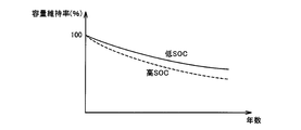
しかしながら、一般的に、リチウムイオン電池では、SOCが高い状態が長時間継続することは劣化の観点から好ましくない。たとえばリチウムイオン電池の劣化が進行すると、満充電容量が低下する。図6は、リチウムイオン電池の使用年数とそのリチウムイオン電池の容量維持率との間の相関関係を説明するための図である。図6を参照して、リチウムイオン電池が新品であるときの容量維持率が100%と定義される。リチウムイオン電池に蓄えられた電力を用いてハイブリッド車両5の走行が繰り返されることにより、リチウムイオン電池は次第に劣化する。リチウムイオン電池の使用年数が長くなるほど容量維持率は小さくなる。すなわち、リチウムイオン電池の満充電容量が低下する。さらに、使用年数に対する容量維持率の低下の度合いは、リチウムイオン電池の充電完了時のSOCが高くなるほど大きくなる。
However, in general, in a lithium ion battery, it is not preferable from the viewpoint of deterioration that a state in which the SOC is high continues for a long time. For example, as the deterioration of a lithium ion battery proceeds, the full charge capacity decreases. FIG. 6 is a diagram for explaining the correlation between the years of use of the lithium ion battery and the capacity retention rate of the lithium ion battery. Referring to FIG. 6, the capacity maintenance rate when the lithium ion battery is new is defined as 100%. The lithium ion battery gradually deteriorates as the hybrid vehicle 5 travels repeatedly using the electric power stored in the lithium ion battery. The capacity maintenance rate decreases as the service life of the lithium ion battery increases. That is, the full charge capacity of the lithium ion battery is reduced. Furthermore, the degree of decrease in the capacity maintenance rate with respect to the years of use increases as the SOC at the completion of charging of the lithium ion battery increases.
ここで、蓄電装置10の充電が完了してからハイブリッド車両5の走行が開始されるまでの時間はユーザによって異なるため、SOCが高い状態が長時間継続する可能性がある。よって、蓄電装置10の満充電容量が低下してしまう虞がある。
Here, since the time from when the charging of the power storage device 10 is completed to when the hybrid vehicle 5 starts to travel varies depending on the user, there is a possibility that the state where the SOC is high continues for a long time. Therefore, the full charge capacity of the power storage device 10 may be reduced.
本実施の形態による電動車両では、蓄電装置10の使用期間を延ばすためのロングライフモードを有する。本実施の形態による電動車両では、通常モード時と、ロングライフモード時との間で、蓄電装置10のSOC制御を以下のように切換える。
The electric vehicle according to the present embodiment has a long life mode for extending the usage period of power storage device 10. In the electric vehicle according to the present embodiment, the SOC control of power storage device 10 is switched between the normal mode and the long life mode as follows.
図5で説明したように、蓄電装置10のSOCについては、制御中心値SOCrに対して、上限側および下限側にそれぞれ制御幅を有するように制御範囲が設定されている。以下では、SOC制御範囲の下限をSOCl(制御下限値)と称し、SOC制御範囲の上限をSOCu(制御上限値)と称することとする。
As described with reference to FIG. 5, for the SOC of power storage device 10, the control range is set so as to have a control width on the upper limit side and the lower limit side with respect to control center value SOCr. Hereinafter, the lower limit of the SOC control range is referred to as SOCl (control lower limit value), and the upper limit of the SOC control range is referred to as SOCu (control upper limit value).
蓄電装置10のSOCについては、基準上限値Smaxおよび基準下限値Sminがさらに設定されている。基準上限値Smaxおよび基準下限値Sminは、これ以上の過充電または過放電が進行するのを回避するために設けられた、SOC制御上の満充電状態および空状態にそれぞれ相当する。
For the SOC of the power storage device 10, a reference upper limit value Smax and a reference lower limit value Smin are further set. The reference upper limit value Smax and the reference lower limit value Smin respectively correspond to a full charge state and an empty state in SOC control provided to avoid further overcharge or overdischarge.
SOC制御範囲は、基準下限値Smin~基準上限値Smaxの範囲内に設定される。すなわち、制御下限値SOClおよび制御上限値SOCuは、基準下限値Sminおよび基準上限値Smaxに対してマージンを有するように設定される。
The SOC control range is set within the range of the reference lower limit value Smin to the reference upper limit value Smax. That is, control lower limit SOCl and control upper limit SOCu are set to have a margin with respect to reference lower limit Smin and reference upper limit Smax.
基準上限値Smaxは、上記のように、蓄電装置10のSOCが満充電状態に達したか否かを判定するための判定値である。本実施の形態による電動車両では、この基準上限値Smaxを、通常モードとロングライフモードとの間で切換える。
The reference upper limit value Smax is a determination value for determining whether or not the SOC of the power storage device 10 has reached the fully charged state as described above. In the electrically powered vehicle according to the present embodiment, this reference upper limit value Smax is switched between the normal mode and the long life mode.
図7を用いて、本実施の形態の電動車両におけるSOCの基準範囲の設定を説明する。
図7を参照して、第1の範囲R1は、通常モードにおけるSOCの基準範囲である。第2の範囲R2は、ロングライフモードにおけるSOCの基準範囲である。Smax1は、第1の範囲R1の上限値、すなわち、通常モードにおける基準上限値Smaxを示す。Smax2は、第2の範囲R2の上限値、すなわち、ロングライフモードにおける基準上限値Smaxを示す。また、第1の範囲R1の下限値、すなわち、通常モードにおける基準下限値と、第2の範囲R2の下限値、すなわち、ロングライフモードにおける基準下限値とはともにSminである。ただし、第2の範囲R2の下限値が第1の範囲R1の下限値よりも大きくてもよい。 The setting of the SOC reference range in the electric vehicle according to the present embodiment will be described with reference to FIG.
Referring to FIG. 7, first range R1 is an SOC reference range in the normal mode. The second range R2 is an SOC reference range in the long life mode. Smax1 indicates the upper limit value of the first range R1, that is, the reference upper limit value Smax in the normal mode. Smax2 indicates the upper limit value of the second range R2, that is, the reference upper limit value Smax in the long life mode. Further, the lower limit value of the first range R1, that is, the reference lower limit value in the normal mode, and the lower limit value of the second range R2, that is, the reference lower limit value in the long life mode are both Smin. However, the lower limit value of the second range R2 may be larger than the lower limit value of the first range R1.
基準上限値Smax1およびSmax2は、蓄電装置10の過充電を防止するために、ともに100%よりも小さい値に設定される。また、基準下限値Sminは、蓄電装置10の過放電を防止するために、0%よりも大きい値に設定される。
Reference upper limit values Smax1 and Smax2 are both set to values smaller than 100% in order to prevent overcharging of power storage device 10. Reference lower limit Smin is set to a value greater than 0% in order to prevent overdischarge of power storage device 10.
ここで、ロングライフモードにおける基準上限値Smax2は、通常モードにおける基準上限値Smax1よりも小さい値に設定される。これにより、ロングライフモード時には、蓄電装置10の充電が完了したときのSOCを、通常モード時よりも下げることができる。この結果、ロングライフモード時には、蓄電装置10の劣化の進行を抑制することができる。
Here, the reference upper limit value Smax2 in the long life mode is set to a value smaller than the reference upper limit value Smax1 in the normal mode. Thereby, at the time of the long life mode, the SOC when the charging of the power storage device 10 is completed can be made lower than that at the time of the normal mode. As a result, in the long life mode, the progress of the deterioration of the power storage device 10 can be suppressed.
このようにロングライフモードで蓄電装置10を充電した場合には、蓄電装置10の満充電容量の低下を抑制することができる。その結果、蓄電装置10の使用年数が長くなっても、ハイブリッド車両5の航続距離を確保することができる。
Thus, when the power storage device 10 is charged in the long life mode, it is possible to suppress a decrease in the full charge capacity of the power storage device 10. As a result, the cruising distance of the hybrid vehicle 5 can be ensured even when the power storage device 10 has been used for a long time.
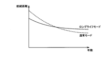
図8は、ロングライフモードでの航続距離と通常モードでの航続距離とを説明するための図である。
FIG. 8 is a diagram for explaining the cruising distance in the long life mode and the cruising distance in the normal mode.
図8を参照して、蓄電装置10の使用年数が短い場合には、蓄電装置10の劣化度合いが小さいために蓄電装置10は多くの電力量を蓄えることができる。したがって、蓄電装置10の使用年数が短い場合には、通常モードでの航続距離がロングライフモードでの航続距離よりも長い。
Referring to FIG. 8, when power storage device 10 has a short service life, power storage device 10 can store a large amount of power because the degree of deterioration of power storage device 10 is small. Therefore, when the service life of power storage device 10 is short, the cruising distance in the normal mode is longer than the cruising distance in the long life mode.
そして、基準上限値Smaxを限度として蓄電装置10が充電されることによって、蓄電装置10の劣化が進行する。しかしながら、ロングライフモードでは、通常モードと比較して、蓄電装置10の劣化の進行が抑制されるため、蓄電装置10の使用年数が長くなっても、蓄電装置10により多くの電力量を蓄えることができる。その結果、通常モードでの航続距離よりも長い航続距離をハイブリッド車両5が走行することができる。
Then, when the power storage device 10 is charged with the reference upper limit value Smax as a limit, the deterioration of the power storage device 10 proceeds. However, in the long life mode, the progress of the deterioration of the power storage device 10 is suppressed as compared with the normal mode, so that even when the power storage device 10 has been used for a long time, a large amount of power can be stored in the power storage device 10. Can do. As a result, the hybrid vehicle 5 can travel a cruising distance longer than the cruising distance in the normal mode.
その一方で、充電モードにロングライフモードが選択された場合においても、蓄電装置10の使用年数が長くなるに従って、蓄電装置10の劣化(満受電容量の低下)が進行する。そのため、蓄電装置10の使用年数が長くなるにつれてハイブリッド車両5の航続距離が短くなってしまう。
On the other hand, even when the long life mode is selected as the charging mode, the deterioration of the power storage device 10 (decrease in the full power receiving capacity) proceeds as the service life of the power storage device 10 increases. Therefore, the cruising distance of hybrid vehicle 5 becomes shorter as the years of use of power storage device 10 become longer.
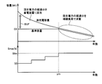
そこで、本実施の形態による電動車両では、蓄電装置10の充電モードとしてロングライフモードが選択された場合には、蓄電装置10の劣化度合いに応じて基準上限値Smax2を可変に設定する。具体的には、蓄電装置10が予め定められた基準容量を保つように、蓄電装置10の満充電容量の低下度合いが大きくなるに従って基準上限値Smax2を上昇させる。
Therefore, in the electric vehicle according to the present embodiment, when long life mode is selected as the charging mode of power storage device 10, reference upper limit value Smax2 is variably set according to the degree of deterioration of power storage device 10. Specifically, the reference upper limit value Smax2 is increased as the degree of decrease in the full charge capacity of the power storage device 10 increases so that the power storage device 10 maintains a predetermined reference capacity.
図9には、充放電制御部150(図4)のさらに詳細な構成が示される。
図9を参照して、充放電制御部150は、基準範囲設定部160と、充放電上限値設定部170と、制御範囲設定部180と、充電指示部190とを含む。 FIG. 9 shows a more detailed configuration of charge / discharge control unit 150 (FIG. 4).
Referring to FIG. 9, charge /discharge control unit 150 includes a reference range setting unit 160, a charge / discharge upper limit setting unit 170, a control range setting unit 180, and a charge instruction unit 190.
図9を参照して、充放電制御部150は、基準範囲設定部160と、充放電上限値設定部170と、制御範囲設定部180と、充電指示部190とを含む。 FIG. 9 shows a more detailed configuration of charge / discharge control unit 150 (FIG. 4).
Referring to FIG. 9, charge /
基準範囲設定部160は、スイッチ56からの信号SLFおよび劣化診断部120からの蓄電装置10の使用年数の計測値CNTに基づいて、蓄電装置10のSOC基準範囲(基準上限値Smaxおよび基準下限値Smin)を設定する。基準範囲設定部160は、スイッチ56から信号SLFを受けたときには、信号SLFが発生した、すなわち、蓄電装置10の充電モードとしてロングライフモードが選択されたと判定する。一方、スイッチ56から信号SLFを受けていないときには、信号SLFが発生していない、すなわち、蓄電装置10の充電モードとして通常モードが選択されたと判定する。
Based on signal SLF from switch 56 and measured value CNT of the age of power storage device 10 from degradation diagnosis unit 120, reference range setting unit 160 determines the SOC reference range (reference upper limit value Smax and reference lower limit value of power storage device 10). Smin) is set. When reference signal setting unit 160 receives signal SLF from switch 56, reference range setting unit 160 determines that signal SLF has been generated, that is, long life mode has been selected as the charging mode of power storage device 10. On the other hand, when signal SLF is not received from switch 56, it is determined that signal SLF is not generated, that is, the normal mode is selected as the charging mode of power storage device 10.
充電モードとしてロングライフモードが選択された場合には、基準範囲設定部160は、基準上限値をSmax2(図7)に設定する。一方、通常モードが充電モードとして選択された場合には、基準範囲設定部160は、基準上限値をSmax1(図7)に設定する。
When the long life mode is selected as the charging mode, the reference range setting unit 160 sets the reference upper limit value to Smax2 (FIG. 7). On the other hand, when the normal mode is selected as the charging mode, the reference range setting unit 160 sets the reference upper limit value to Smax1 (FIG. 7).
さらに基準範囲設定部160は、ロングライフモードが選択された場合には、蓄電装置10の使用年数の計測値CNTに応じて、基準上限値Smax2を可変に設定する。具体的には、基準範囲設定部160は、蓄電装置10の使用年数の増加に応じて、基準上限値Smax2を上昇させる。
Further, when the long life mode is selected, the reference range setting unit 160 variably sets the reference upper limit value Smax2 according to the measured value CNT of the years of use of the power storage device 10. Specifically, reference range setting unit 160 increases reference upper limit value Smax2 in accordance with an increase in the number of years of use of power storage device 10.
図10は、蓄電装置10の使用年数に対する基準上限値Smax2の設定を説明する概念図である。
FIG. 10 is a conceptual diagram illustrating the setting of the reference upper limit value Smax2 with respect to the years of use of the power storage device 10.
図10を参照して、ロングライフモードにおける基準上限値Smax2は、蓄電装置10の新品相当時には、デフォルト値であるS0に設定される。S0は、蓄電装置10の新品時の満充電容量に対する基準容量の比率を示したものである。基準容量は、満充電容量に対してマージンを有する値に設定される。基準容量については、ハイブリッド車両5の航続距離の目標値を達成するのに必要とされる蓄電装置10の残容量C0がデフォルト値に設定される。蓄電装置10の残容量が基準容量に達すると、蓄電装置10のSOCが基準上限値Smax2に到達するため、蓄電装置10が満充電状態に達したと判定される。すなわち、基準容量は、蓄電装置10が満充電状態に到達したか否かを判別するための閾値に相当する。
Referring to FIG. 10, reference upper limit value Smax2 in the long life mode is set to S0 which is a default value when power storage device 10 is equivalent to a new product. S0 indicates the ratio of the reference capacity to the full charge capacity when the power storage device 10 is new. The reference capacity is set to a value having a margin with respect to the full charge capacity. As for the reference capacity, the remaining capacity C0 of the power storage device 10 required to achieve the target value of the cruising distance of the hybrid vehicle 5 is set to a default value. When the remaining capacity of power storage device 10 reaches the reference capacity, the SOC of power storage device 10 reaches reference upper limit value Smax2, so that it is determined that power storage device 10 has reached a fully charged state. That is, the reference capacity corresponds to a threshold value for determining whether or not the power storage device 10 has reached a fully charged state.
図6に示したように、蓄電装置10の使用年数が長くなるに従って、蓄電装置10の満充電容量が減少する。そのため、基準上限値Smax2をデフォルト値S0に固定すると、蓄電装置10の使用年数が長い場合には、SOCが基準上限値Smax2に達するまで蓄電装置10を充電しても、蓄電装置10の残容量が基準容量に満たない可能性がある。その結果、ハイブリッド車両5の航続距離が目標値に達成しない虞がある。
As shown in FIG. 6, the full charge capacity of the power storage device 10 decreases as the age of the power storage device 10 increases. Therefore, if reference upper limit value Smax2 is fixed to default value S0, if the power storage device 10 has been used for a long time, the remaining capacity of power storage device 10 will remain even if the power storage device 10 is charged until the SOC reaches the reference upper limit value Smax2. May not meet the standard capacity. As a result, the cruising distance of the hybrid vehicle 5 may not reach the target value.
このため、基準範囲設定部160は、蓄電装置10の劣化度合い(満充電容量の低下度合い)に応じて、充電完了時に基準容量が確保されるように、基準上限値Smax2を上昇させる。具体的には、基準範囲設定部160は、劣化診断部120からの計測値CNTに基づいて、蓄電装置10の使用年数が所定の年数y0年に達したと判断されると、基準上限値Smax2をデフォルト値S0からS1に上昇させる。S1は、蓄電装置10の使用年数がy0年に達したときの満充電容量に対する基準容量C0の比率に相当する。
For this reason, the reference range setting unit 160 increases the reference upper limit value Smax2 in accordance with the degree of deterioration of the power storage device 10 (the degree of decrease in the full charge capacity) so that the reference capacity is secured when charging is completed. Specifically, when reference range setting unit 160 determines that the number of years of use of power storage device 10 has reached a predetermined number of years y0 based on measurement value CNT from degradation diagnosis unit 120, reference upper limit value Smax2 Is increased from the default value S0 to S1. S1 corresponds to the ratio of the reference capacity C0 to the full charge capacity when the power storage device 10 has been used for y0 years.
y0年から2y0年までの使用時間では、基準上限値Smax2がS1に保たれる。この間に蓄電装置10の満充電容量が減少する。使用年数が2y0年に達したときには、基準範囲設定部160は、基準上限値Smax2をS1からS2へ上昇させる。S2は、蓄電装置10の使用年数が2y0年に達したときの満充電容量に対する基準容量C0の比率に相当する。
In the usage time from year y0 to year 2y0, the reference upper limit value Smax2 is maintained at S1. During this time, the full charge capacity of the power storage device 10 decreases. When the service life reaches 2y0, the reference range setting unit 160 increases the reference upper limit value Smax2 from S1 to S2. S2 corresponds to the ratio of the reference capacity C0 to the full charge capacity when the usage period of the power storage device 10 reaches 2y0 years.
なお、図10では、所定の使用年数y0ごとに基準上限値Smax2を上昇させる構成としたが、基準上限値Smax2を上昇させる回数を1回でもよい。蓄電装置10の標準的な使用年数、蓄電装置10の満充電容量および目標航続距離等に基づいて、基準上限値Smax2を上昇させる回数を定めることができる。
In addition, in FIG. 10, although it was set as the structure which raises the reference | standard upper limit value Smax2 for every predetermined years of use y0, the frequency | count of raising the reference | standard upper limit value Smax2 may be one time. The number of times the reference upper limit value Smax2 is increased can be determined based on the standard years of use of the power storage device 10, the full charge capacity of the power storage device 10, the target cruising distance, and the like.
また、図11に示すように、ハイブリッド車両5の走行距離に応じて基準上限値Smax2を上昇させてもよい。図11は、ハイブリッド車両5の走行距離に対する基準上限値Smax2の設定を説明する概念図である。図11を参照して、基準範囲設定部160は、劣化診断部120からの走行距離の計測値CNTに基づいて、ハイブリッド車両5の走行距離が所定の距離x0に達したと判断されると、基準上限値Smax2をデフォルト値S0からS1に上昇させる。図11では、S1は、ハイブリッド車両5の走行距離が一定の距離x0に達したときの満充電容量に対する基準容量C0の比率に相当する。走行距離がx0から2x0までの時間では、基準上限値Smax2がS1に保たれる。この間に、蓄電装置10の満充電容量が減少する。走行距離が2x0年に達したとき、基準範囲設定部160は、基準上限値Smax2をS1からS2へ上昇させる。S2は、ハイブリッド車両5の走行距離が2x0に達したときの満充電容量に対する基準容量C0の比率に相当する。
Further, as shown in FIG. 11, the reference upper limit value Smax2 may be increased according to the travel distance of the hybrid vehicle 5. FIG. 11 is a conceptual diagram illustrating the setting of the reference upper limit value Smax2 with respect to the travel distance of the hybrid vehicle 5. Referring to FIG. 11, when reference range setting unit 160 determines that traveling distance of hybrid vehicle 5 has reached a predetermined distance x0 based on measured value CNT of the traveling distance from deterioration diagnosis unit 120, The reference upper limit value Smax2 is increased from the default value S0 to S1. In FIG. 11, S1 corresponds to the ratio of the reference capacity C0 to the full charge capacity when the travel distance of the hybrid vehicle 5 reaches a certain distance x0. The reference upper limit value Smax2 is maintained at S1 during the travel distance from x0 to 2x0. During this time, the full charge capacity of the power storage device 10 decreases. When the travel distance reaches 2 × 0 years, the reference range setting unit 160 increases the reference upper limit value Smax2 from S1 to S2. S2 corresponds to the ratio of the reference capacity C0 to the full charge capacity when the travel distance of the hybrid vehicle 5 reaches 2x0.
なお、図10と同様に、図11においても、所定の距離x0ごとに基準上限値Smax2を上昇させる構成に代えて、基準上限値Smax2を上昇させる回数を1回でもよい。蓄電装置10の標準的な使用年数、蓄電装置10の満充電容量および目標航続距離等に基づいて、基準上限値Smax2を上昇させる回数を定めることができる。
As in FIG. 10, in FIG. 11, the reference upper limit value Smax2 may be increased once instead of increasing the reference upper limit value Smax2 every predetermined distance x0. The number of times the reference upper limit value Smax2 is increased can be determined based on the standard years of use of the power storage device 10, the full charge capacity of the power storage device 10, the target cruising distance, and the like.
図12は、本実施の形態によるSOC制御により達成可能な電動車両の航続距離を説明する概念図である。図12の実線は、蓄電装置10の劣化度合いに基づいた所定のタイミングで基準上限値Smax2を上昇させた場合のハイブリッド車両5の航続距離を示す。図12の点線は、基準上限値Smax2をデフォルト値S0に固定させた場合のハイブリッド車両5の航続距離を示す。
FIG. 12 is a conceptual diagram illustrating the cruising distance of an electric vehicle that can be achieved by the SOC control according to the present embodiment. The solid line in FIG. 12 indicates the cruising distance of the hybrid vehicle 5 when the reference upper limit value Smax2 is increased at a predetermined timing based on the degree of deterioration of the power storage device 10. The dotted line in FIG. 12 indicates the cruising distance of the hybrid vehicle 5 when the reference upper limit value Smax2 is fixed to the default value S0.
図12を参照して、基準上限値Smax2をデフォルト値S0に固定させた場合には、蓄電装置10の使用年数が長くなるに従って航続距離が減少する。蓄電装置10の使用年数が長くなるに従って満充電容量が減少するためである。これに対して、蓄電装置10の劣化度合いに基づいた適当なタイミングで基準上限値Smax2を上昇させた場合には、蓄電装置10の残容量を基準容量C0に保つことができるため、航続距離を延ばすことができる。これにより、目標の使用年数が経過したときに、航続距離の目標値を達成することができる。
Referring to FIG. 12, when reference upper limit value Smax2 is fixed to default value S0, the cruising distance decreases as the years of use of power storage device 10 increase. This is because the full charge capacity decreases as the number of years of use of the power storage device 10 increases. On the other hand, when the reference upper limit Smax2 is increased at an appropriate timing based on the degree of deterioration of the power storage device 10, the remaining capacity of the power storage device 10 can be maintained at the reference capacity C0. Can be extended. As a result, the target value of the cruising distance can be achieved when the target years of use have elapsed.
図13は、図9の基準範囲設定部160による基準上限値Smaxの設定を実現するための制御処理手順を示したフローチャートである。なお、図13に示すフローチャートは、ロングライフモードが充電モードに設定された場合、一定時間ごとまたは所定の条件が成立するごとに実行される。
FIG. 13 is a flowchart showing a control processing procedure for realizing the setting of the reference upper limit value Smax by the reference range setting unit 160 of FIG. Note that the flowchart shown in FIG. 13 is executed every predetermined time or every time a predetermined condition is satisfied when the long life mode is set to the charging mode.
図13を参照して、基準範囲設定部160は、ステップS01では、劣化診断部120からの計測値CNTに基づいて、蓄電装置10の使用年数が基準値(x0)に達したか否かを判定する。蓄電装置10の使用年数が基準値に達していないと判定された場合(ステップS01においてNO)には、基準範囲設定部160は、ステップS04により、基準上限値Smax2の上昇を抑制する。すなわち、基準上限値Smax2は変化しない。ステップS04の処理が終了すると、全体の処理はメインルーチンに戻される。
Referring to FIG. 13, in step S <b> 01, reference range setting unit 160 determines whether the age of power storage device 10 has reached the reference value (x0) based on measurement value CNT from deterioration diagnosis unit 120. judge. When it is determined that the age of power storage device 10 has not reached the reference value (NO in step S01), reference range setting unit 160 suppresses an increase in reference upper limit value Smax2 in step S04. That is, the reference upper limit value Smax2 does not change. When the process of step S04 ends, the entire process is returned to the main routine.
これに対して、蓄電装置10の使用年数が基準値に達したと判定された場合(ステップS01においてYES)には、基準範囲設定部160は、ステップS02により、基準上限値Smax2を上昇させる。このとき、基準範囲設定部160は、基準容量C0を確保できる値まで基準上限値Smax2を上昇させる。
On the other hand, when it is determined that the number of years of use of power storage device 10 has reached the reference value (YES in step S01), reference range setting unit 160 increases reference upper limit value Smax2 in step S02. At this time, the reference range setting unit 160 increases the reference upper limit value Smax2 to a value that can secure the reference capacity C0.
次に、基準範囲設定部160は、ステップS03により、蓄電装置10の使用年数の計測値CNTを0に戻す。ステップS03の処理が終了すると、全体の処理はメインルーチンに戻される。
Next, the reference range setting unit 160 returns the measured value CNT of the service life of the power storage device 10 to 0 in step S03. When the process of step S03 ends, the entire process is returned to the main routine.
再び図9を参照して、充放電上限値設定部170は、電池温度TbおよびSOC推定値(#SOC)に少なくとも基づいて、蓄電装置10で充放電が許容される最大の電力値(充電電力上限値Winおよび放電電力上限値Wout)を設定する。SOC推定値(♯SOC)が低下すると、放電電力上限値Woutは徐々に低く設定される。反対に、SOC推定値(♯SOC)が高くなると、充電電力上限値Winは徐々に低下するように設定される。
Referring to FIG. 9 again, charge / discharge upper limit setting unit 170 is configured to provide the maximum power value (charge power) that is allowed to be charged / discharged by power storage device 10 based at least on battery temperature Tb and estimated SOC value (#SOC). An upper limit value Win and a discharge power upper limit value Wout) are set. When SOC estimated value (#SOC) decreases, discharge power upper limit value Wout is set gradually lower. Conversely, when SOC estimated value (#SOC) increases, charging power upper limit value Win is set to gradually decrease.
制御範囲設定部180は、蓄電装置10のSOC制御範囲を設定する。SOC制御範囲は、上述のように、制御中心値SOCrに対して上限側および下限側にそれぞれ制御幅を有するように設定される。
Control range setting unit 180 sets the SOC control range of power storage device 10. As described above, the SOC control range is set to have control widths on the upper limit side and the lower limit side with respect to the control center value SOCr.
充電指示部190は、SOC推定値(♯SOC)が制御範囲設定部180によるSOC制御範囲よりも低下した場合、すなわち、少なくとも♯SOC<SOClとなったときには、蓄電装置10の充電を指示する。すなわち、Pch>0に設定する。あるいは、SOCl<♯SOC<SOCrの段階で、予備的にPch>0としてもよい。Pch>0となると、エンジン18の作動が要求される。エンジン18の停止時には、エンジン18が始動される。そして、エンジン出力要求に充電電力指令値Pchが上乗せされる。
Charging instruction unit 190 instructs charging of power storage device 10 when SOC estimated value (#SOC) falls below the SOC control range by control range setting unit 180, that is, when at least #SOC <SOCl. That is, Pch> 0 is set. Alternatively, Pch> 0 may be preliminarily set at the stage of SOCl <#SOC <SOCr. When Pch> 0, the operation of the engine 18 is required. When the engine 18 is stopped, the engine 18 is started. Then, the charging power command value Pch is added to the engine output request.
反対に、SOC推定値(♯SOC)が低下していないときには、充電指示部190は、Pch=0に設定する。このときには、蓄電装置10の充電を目的にエンジン18が作動することはない。また、SOCr<♯SOC<SOCuのときは、Pchを放電側に設定することによって、蓄電装置10の放電が指定される。
On the other hand, when the estimated SOC value (#SOC) has not decreased, charging instruction unit 190 sets Pch = 0. At this time, engine 18 does not operate for the purpose of charging power storage device 10. When SOCr <#SOC <SOCu, the discharge of power storage device 10 is specified by setting Pch to the discharge side.
図9に示す構成において、SOC推定値(♯SOC)が基準上限値Smaxに近づくと、充放電上限値設定部170は、充電電力上限値Winを低く設定する。これにより、蓄電装置10の過充電が回避される。
In the configuration shown in FIG. 9, when the SOC estimated value (#SOC) approaches the reference upper limit value Smax, the charge / discharge upper limit value setting unit 170 sets the charging power upper limit value Win low. Thereby, the overcharge of the electrical storage apparatus 10 is avoided.
その一方で、減速時や降坂走行時にモータジェネレータMG2が発生した回生電力が充電電力上限値Winを超える場合には、モータジェネレータMG2による回生発電が制限あるいは禁止されることなる。そのため、ハイブリッド車両5全体で必要な制動力を発生させることができない虞がある。なお、回生発電が制限あるいは禁止される場合には、モータジェネレータMG2による回生制動力と、図示しない油圧ブレーキ機構による液圧制動力とを協調させて、車両全体での要求制動力を発生させることができる。特に回生発電が禁止される場合には、油圧ブレーキ機構のみによって車両全体での要求制動力を発生させることができる。
On the other hand, when the regenerative power generated by the motor generator MG2 during deceleration or traveling downhill exceeds the charging power upper limit Win, regenerative power generation by the motor generator MG2 is restricted or prohibited. Therefore, there is a possibility that a necessary braking force cannot be generated in the entire hybrid vehicle 5. When regenerative power generation is restricted or prohibited, the regenerative braking force by motor generator MG2 and the hydraulic braking force by a hydraulic brake mechanism (not shown) may be coordinated to generate the required braking force for the entire vehicle. it can. In particular, when regenerative power generation is prohibited, the required braking force for the entire vehicle can be generated only by the hydraulic brake mechanism.
このような回生制動力および液圧性動力を協調させて車両全体での要求制動力を確保する制動力制御では、モータジェネレータMG2による回生発電が制限あるいは禁止されると、回生制動力の減少分に対応させて液圧制動力を増加させる必要がある。しかしながら、回生制動力が急激に減少してしまうような場合には、液圧制動力の増加(液圧の上昇)が追従できず、制動時のフィーリングを悪化させる虞がある。
In the braking force control that secures the required braking force for the entire vehicle by coordinating the regenerative braking force and the hydraulic power, if the regenerative power generation by the motor generator MG2 is restricted or prohibited, the regenerative braking force is reduced. Accordingly, it is necessary to increase the hydraulic braking force. However, in the case where the regenerative braking force is suddenly reduced, the increase in the hydraulic braking force (an increase in the hydraulic pressure) cannot be followed, which may deteriorate the feeling during braking.
本実施の形態による電動車両では、上述のように、ロングライフモードにおける基準上限値Smax2は、通常モードにおける基準上限値Smax1よりも低い。したがって、充電モードとしてロングライフモードが選択されている場合には、通常モードが選択されている場合と比較して、充電電力上限値Winがより低く設定されるため、回生発電の制限度合いが高くなる。その結果、制動時のフィーリングの悪化がより顕著となる虞がある。
In the electric vehicle according to the present embodiment, as described above, the reference upper limit value Smax2 in the long life mode is lower than the reference upper limit value Smax1 in the normal mode. Therefore, when the long life mode is selected as the charging mode, the charging power upper limit value Win is set lower than when the normal mode is selected, so the degree of restriction on regenerative power generation is high. Become. As a result, there is a risk that the deterioration of the feeling during braking becomes more remarkable.
したがって、本実施の形態による電動車両では、充電モードとしてロングライフモードが選択されている場合において、モータジェネレータMG2により発電された回生電力が充電電力上限値Winを超えるときには、蓄電装置10の満充電容量に対して基準容量が有するマージンの大きさに応じて、充電電力上限値Winからの回生電力の超過分の回収先を、以下のように切換える。
Therefore, in the electrically powered vehicle according to the present embodiment, when long life mode is selected as the charging mode, when regenerative power generated by motor generator MG2 exceeds charge power upper limit Win, full storage device 10 is fully charged. In accordance with the size of the margin of the reference capacity relative to the capacity, the recovery destination of the excess regenerative power from the charging power upper limit Win is switched as follows.
図14を用いて、本実施の形態による電動車両の回生制動時における蓄電装置10の充電制御を説明する。
Referring to FIG. 14, charging control of power storage device 10 during regenerative braking of the electric vehicle according to the present embodiment will be described.
図14には、本実施の形態の電動車両における蓄電装置10の満充電容量および基準容量の推移が示される。図14を参照して、蓄電装置10の使用年数が長くなるにつれて、蓄電装置10の満充電容量が減少する。基準容量は、満充電容量に対してマージンを有するように設定される。基準容量は、上述のように、ハイブリッド車両5の航続距離の目標値を達成するのに必要な残容量C0がデフォルト値に設定される。蓄電装置10のSOCの基準上限値Smaxは、蓄電装置10の満充電容量に対する基準容量の比率に相当する。
FIG. 14 shows changes in the full charge capacity and the reference capacity of power storage device 10 in the electric vehicle according to the present embodiment. Referring to FIG. 14, the full charge capacity of power storage device 10 decreases as the age of power storage device 10 increases. The reference capacity is set to have a margin with respect to the full charge capacity. As described above, the remaining capacity C0 required to achieve the target value of the cruising distance of the hybrid vehicle 5 is set to the default value as the reference capacity. The reference upper limit value Smax of the SOC of the power storage device 10 corresponds to the ratio of the reference capacity to the full charge capacity of the power storage device 10.
充電モードとしてロングライフモードが選択された場合には、基準範囲設定部160(図9)は、上述のように、蓄電装置10が基準容量C0(デフォルト値)を保つように、蓄電装置10の満充電容量の低下度合いに応じて基準上限値Smax2を上昇させる。
When the long life mode is selected as the charging mode, the reference range setting unit 160 (FIG. 9) sets the power storage device 10 so that the power storage device 10 maintains the reference capacity C0 (default value) as described above. The reference upper limit value Smax2 is increased according to the degree of decrease in the full charge capacity.
そして、蓄電装置10の劣化に伴なって満充電容量が徐々に低下することにより、使用年数が所定年数ythのときに満充電容量がC0(デフォルト値)に達すると、基準範囲設定部160は、基準容量をデフォルト値C0から満充電容量に変更する。すなわち、使用年数が所定年数ythに達した後は、使用年数が長くなるに従って基準容量はデフォルト値C0から徐々に低下する。
Then, as the full charge capacity gradually decreases as the power storage device 10 deteriorates, when the full charge capacity reaches C0 (default value) when the service life is the predetermined year yth, the reference range setting unit 160 The reference capacity is changed from the default value C0 to the full charge capacity. That is, after the usage years reach the predetermined number of years yth, the reference capacity gradually decreases from the default value C0 as the usage years increase.
この結果、基準上限値Smax2は、蓄電装置10の使用年数が所定年数ythに達するまではS0をデフォルト値として、使用年数が長くなるに従ってデフォルト値S0よりも上昇する。そして、使用年数が所定年数ythに達した後は、基準上限値Smax2は、満充電容量に対する基準容量の比率に対応する所定値Slimに固定される。
As a result, the reference upper limit value Smax2 becomes higher than the default value S0 as the service life becomes longer, with S0 as a default value until the service life of the power storage device 10 reaches the predetermined year yth. After the service life reaches the predetermined number of years yth, the reference upper limit value Smax2 is fixed to a predetermined value Slim corresponding to the ratio of the reference capacity to the full charge capacity.
上述のように、基準容量は、蓄電装置10が満充電状態に達したか否かを判別するための閾値であり、満充電容量に対してマージンを有するようにデフォルト値C0が設定される。図中のBUFはマージンを示す。図14に示すように、マージンBUFは、使用年数が所定年数ythに達するまでは、満充電容量の低下に伴なって減少し、使用年数が所定年数ythに達した後は略零となる。すなわち、蓄電装置10の劣化度合いが大きくなるにつれてマージンBUFは小さくなる。走行制御部200(図4)は、モータジェネレータMG2により発生された回生電力が充電電力上限値Winを超える場合には、マージンBUFの低下度合いに応じて、充電電力上限値Winからの超過分を蓄電装置10に回生するための制御と、当該超過分を補機負荷を用いて消費するための制御とを切換える。
As described above, the reference capacity is a threshold value for determining whether or not the power storage device 10 has reached the full charge state, and the default value C0 is set so as to have a margin with respect to the full charge capacity. BUF in the figure indicates a margin. As shown in FIG. 14, the margin BUF decreases as the full charge capacity decreases until the number of years of use reaches the predetermined number of years yth, and becomes substantially zero after the number of years of use reaches the predetermined number of years yth. That is, the margin BUF decreases as the degree of deterioration of the power storage device 10 increases. When the regenerative power generated by motor generator MG2 exceeds charge power upper limit Win, traveling control unit 200 (FIG. 4) determines an excess from charge power upper limit Win according to the degree of decrease in margin BUF. The control for regenerating the power storage device 10 and the control for consuming the excess using an auxiliary machine load are switched.
具体的には、走行制御部200は、残容量に設けられたマージンBUFを、モータジェネレータMG2により発電された回生電力を蓄えるための電力バッファとして機能させる。したがって、充電電力上限値Winに対する回生電力の超過分は、この電力バッファに回収される。すなわち、モータジェネレータMG2が発生した回生電力は、蓄電装置10に回生される。これにより、蓄電装置10の蓄積電力を増やすことができるので、ハイブリッド車両5のエネルギ効率を向上することができる。
Specifically, traveling control unit 200 causes margin BUF provided in the remaining capacity to function as a power buffer for storing regenerative power generated by motor generator MG2. Therefore, the excess of the regenerative power with respect to the charging power upper limit value Win is collected in this power buffer. That is, the regenerative power generated by motor generator MG2 is regenerated in power storage device 10. As a result, the stored power of power storage device 10 can be increased, so that the energy efficiency of hybrid vehicle 5 can be improved.
そして、マージンBUFが略零にまで低下すると、走行制御部200は、充電電力上限値Winに対するモータジェネレータMG2の回生電力の超過分の回収先を、蓄電装置10における電力バッファから補機負荷(補機42およびエアコン44など)に変更する。すなわち、モータジェネレータMG2の回生電力の超過分を補機負荷を用いて消費する。
Then, when margin BUF decreases to substantially zero, traveling control unit 200 collects the recovery destination of the excess regenerative power of motor generator MG2 with respect to charging power upper limit Win from the power buffer in power storage device 10 as an auxiliary load (complementary load). Machine 42 and air conditioner 44). That is, the excess of the regenerative power of motor generator MG2 is consumed using the auxiliary load.
このように、モータジェネレータMG2が発生した回生電力が充電電力上限値Winを超える場合には、走行制御部200は、蓄電装置10の満充電容量と基準容量との相関関係に応じて、充電電力上限値Winに対する回生電力の超過分の回収先として、蓄電装置10における電力バッファ(図14のマージンBUF)および補機負荷のいずれか一方を選択する。これにより、モータジェネレータMG2による回生発電が制限あるいは禁止されるのを回避できるため、制動時制御におけるフィーリングの悪化を防止しつつ、車両全体での要求性動力を確保することが可能となる。
Thus, when the regenerative power generated by motor generator MG2 exceeds charge power upper limit Win, traveling control unit 200 determines the charge power according to the correlation between the full charge capacity of power storage device 10 and the reference capacity. As a collection destination of excess regenerative power with respect to the upper limit value Win, either the power buffer (margin BUF in FIG. 14) or the auxiliary load in the power storage device 10 is selected. Thereby, since it is possible to avoid the regenerative power generation by motor generator MG2 being restricted or prohibited, it is possible to secure the required power in the entire vehicle while preventing deterioration of the feeling during braking control.
図15は、本実施の形態による電動車両における回生制動時の蓄電装置の充電制御を実現するための制御処理手順を示したフローチャートである。
FIG. 15 is a flowchart showing a control processing procedure for realizing charge control of the power storage device during regenerative braking in the electric vehicle according to the present embodiment.
図15を参照して、走行制御部200は、ステップS11により、走行モード選択部210から送出される走行モードフラグFMに基づいて、ハイブリッド車両5が走行中であるか否かを判定する。ハイブリッド車両5が走行中でないとき(ステップS11においてNO)には、蓄電装置10の充電制御に係る処理は終了する。
Referring to FIG. 15, traveling control unit 200 determines whether hybrid vehicle 5 is traveling based on traveling mode flag FM sent from traveling mode selecting unit 210 in step S11. When hybrid vehicle 5 is not traveling (NO in step S11), the process related to the charging control of power storage device 10 ends.
これに対して、ハイブリッド車両5が走行中であるとき(ステップS11においてYES)には、走行制御部200は、ステップS12により、モータジェネレータMG2の出力要求に基づいてモータジェネレータMG2が回生中であるか否かを判定する。具体的には、走行制御部200は、モータジェネレータMG2のトルク指令値とモータ回転数との符号が異なるとき、モータジェネレータMG2は回生中であると判定する。モータジェネレータMG2が回生中でないとき(ステップS12においてNO)には、処理は終了する。
In contrast, when hybrid vehicle 5 is traveling (YES in step S11), traveling control unit 200 regenerates motor generator MG2 based on the output request of motor generator MG2 in step S12. It is determined whether or not. Specifically, traveling control unit 200 determines that motor generator MG2 is regenerating when the torque command value of motor generator MG2 differs from the sign of the motor speed. When motor generator MG2 is not regenerating (NO in step S12), the process ends.
モータジェネレータMG2が回生中であると判定されると(ステップS12においてYES)、走行制御部200は、ステップS13では、モータジェネレータMG2により発電された回生電力が蓄電装置10の充電電力上限値Winを超えるか否かを判定する。なお、ステップS13における充電電力上限値Winは、図13に示す処理フローによって設定された基準上限値Smaxに基づいて充放電上限値設定部170により算出されたものである。
If it is determined that motor generator MG2 is regenerating (YES in step S12), traveling control unit 200 determines in step S13 that the regenerative power generated by motor generator MG2 is equal to charging power upper limit value Win of power storage device 10. It is determined whether or not it exceeds. The charging power upper limit value Win in step S13 is calculated by the charge / discharge upper limit setting unit 170 based on the reference upper limit value Smax set by the processing flow shown in FIG.
モータジェネレータMG2が発生した回生電力が充電電力上限値Win以下となるとき(ステップS13においてNO)には、走行制御部200は、ステップS15により、この回生電力を蓄電装置10の充電電力として回収する。
When regenerative power generated by motor generator MG2 is equal to or lower than charging power upper limit Win (NO in step S13), traveling control unit 200 collects this regenerative power as charging power for power storage device 10 in step S15. .
これに対して、モータジェネレータMG2により発電された回生電力が充電電力上限値Winを超えるとき(ステップS13においてYES)には、走行制御部200は、ステップS14では、蓄電装置10の基準上限値Smaxを所定値Slimと比較する。このステップS14の処理は、蓄電装置10の満充電容量と基準容量C0とを比較することに相当する。そして、走行制御部200は、基準上限値Smaxが所定値Slimに達していないとき(ステップS14においてNO)、すなわち、満充電容量が基準容量C0に達していないときには、走行制御部200は、ステップS16により、充電電力上限値Winに対する回生電力の超過分を蓄電装置10における電力バッファBUFで回収する。
In contrast, when regenerative power generated by motor generator MG2 exceeds charging power upper limit Win (YES in step S13), traveling control unit 200 in step S14, reference upper limit Smax of power storage device 10 is determined. Is compared with a predetermined value Slim. The process of step S14 corresponds to comparing the full charge capacity of the power storage device 10 with the reference capacity C0. When the reference upper limit value Smax has not reached the predetermined value Slim (NO in step S14), that is, when the full charge capacity has not reached the reference capacity C0, the travel control unit 200 By S16, the excess of the regenerative power with respect to the charging power upper limit value Win is collected by the power buffer BUF in the power storage device 10.
一方、基準上限値Smaxが所定値Slimに達しているとき(ステップS14においてYES)、すなわち、満充電容量が基準容量に達しているときには、走行制御部200は、ステップS17により、回生電力の超過分を補機42およびエアコン44を用いて消費する。
On the other hand, when reference upper limit value Smax has reached predetermined value Slim (YES in step S14), that is, when the full charge capacity has reached the reference capacity, traveling control unit 200 exceeds the regenerative power in step S17. The amount is consumed using the auxiliary machine 42 and the air conditioner 44.
以上に述べたように、この発明の実施の形態によれば、蓄電装置の満充電容量に対してマージンを有するように、SOC制御上の満充電状態を設定するとともに、蓄電装置の劣化(満充電容量の低下)に起因するマージンの低下度合いに応じて、上記満充電状態に対応付けて規定された充電電力上限値からの回生電力の超過分を蓄電装置に回生する制御(本願発明での「第1の制御」に相当)と、当該超過分を補機負荷を用いて消費する制御(本願発明での「第2の制御」に相当)とを切換える。このように蓄電装置の劣化度合いに応じた蓄電装置の充電制御および電動機の回生制御を行なうことにより、蓄電装置の劣化を抑制して電動車両の航続距離を確保しつつ、電動機による回生発電が制限または禁止されることによる制動時のフィーリングの悪化を防止することができる。
As described above, according to the embodiment of the present invention, the full charge state in the SOC control is set so as to have a margin with respect to the full charge capacity of the power storage device, and the deterioration (full charge) of the power storage device is set. Control that regenerates the excess of regenerative power from the charge power upper limit value defined in association with the full charge state to the power storage device (according to the present invention) "Corresponding to" first control ") and control (corresponding to" second control "in the present invention) for consuming the excess using the auxiliary load. In this way, by performing charging control of the power storage device and regenerative control of the electric motor according to the degree of deterioration of the power storage device, regenerative power generation by the motor is restricted while suppressing the deterioration of the power storage device and ensuring the cruising distance of the electric vehicle. Or the deterioration of the feeling at the time of braking by being prohibited can be prevented.
なお、本実施の形態による車載蓄電装置の充電制御が適用される電動車両は、図1に例示したハイブリッド車両5に限定されるものではない。本発明は、電動機による回生制動により発生した電力を蓄電装置に回生する構成を有するものであれば、搭載される電動機(モータジェネレータ)の個数や駆動系の構成に関わらず、ハイブリッド車両の他に、エンジンを搭載しない電気自動車や燃料電池自動車等を含む電動車両全般に共通に適用できる。特に、ハイブリッド車両の構成についても、図1の例示に限定されることはなく、パラレル式のハイブリッド車両を始めとして、任意の構成のものに本願発明を適用可能である点について、確認的に記載する。
Note that the electric vehicle to which the charging control of the in-vehicle power storage device according to the present embodiment is applied is not limited to the hybrid vehicle 5 illustrated in FIG. The present invention is not limited to a hybrid vehicle, as long as it has a configuration that regenerates electric power generated by regenerative braking by an electric motor in a power storage device, regardless of the number of mounted electric motors (motor generators) and the configuration of a drive system. It can be commonly applied to all electric vehicles including electric vehicles and fuel cell vehicles not equipped with an engine. In particular, the configuration of the hybrid vehicle is not limited to the example shown in FIG. 1, and the fact that the present invention can be applied to any configuration including a parallel hybrid vehicle is confirmed. To do.
今回開示された実施の形態はすべての点で例示であって制限的なものではないと考えられるべきである。本発明の範囲は上記した説明ではなくて請求の範囲によって示され、請求の範囲と均等の意味および範囲内でのすべての変更が含まれることが意図される。
The embodiment disclosed this time should be considered as illustrative in all points and not restrictive. The scope of the present invention is defined by the terms of the claims, rather than the description above, and is intended to include any modifications within the scope and meaning equivalent to the terms of the claims.
この発明は、蓄電装置と、回生制動力を発生する電動機とを搭載した電動車両に適用することができる。
The present invention can be applied to an electric vehicle equipped with a power storage device and an electric motor that generates a regenerative braking force.
5 ハイブリッド車両、6 コンバータ、7 システムメインリレー、8-1,8-2 インバータ、10 蓄電装置、11 監視ユニット、12 温度センサ、13,16 電圧センサ、14 電流センサ、15 電力制御ユニット、18 エンジン、22 動力分割機構、24F 駆動輪、30 制御装置、40 DC/DCコンバータ、42 補機、44 エアコン、50 充電器、52 充電リレー、54 コネクタ受入部、56 スイッチ、60 商用電源、62 コネクタ部、95 減速軸、110 状態推定部、120 劣化診断部、150 充放電制御部、160 基準範囲設定部、170 充放電上限値設定部、180 制御範囲設定部、190 充電指示部、200 走行制御部、202 サンギヤ、204 ピニオンギヤ、206 キャリア、208 リングギヤ、210 走行モード選択部、250 配分部、260 インバータ制御部、270 コンバータ制御部、280 補機制御部、MG1,MG2 モータジェネレータ、MNL 負母線、MPL 正母線、NL 負線、PL 正線、SB 補機バッテリ。
5 hybrid vehicle, 6 converter, 7 system main relay, 8-1, 8-2 inverter, 10 power storage device, 11 monitoring unit, 12 temperature sensor, 13, 16 voltage sensor, 14 current sensor, 15 power control unit, 18 engine , 22 Power split mechanism, 24F drive wheel, 30 control device, 40 DC / DC converter, 42 auxiliary machine, 44 air conditioner, 50 charger, 52 charge relay, 54 connector receiving part, 56 switch, 60 commercial power supply, 62 connector part , 95 deceleration axis, 110 state estimation unit, 120 deterioration diagnosis unit, 150 charge / discharge control unit, 160 reference range setting unit, 170 charge / discharge upper limit setting unit, 180 control range setting unit, 190 charge instruction unit, 200 travel control unit , 202 Sungear, 204 Pinio Gear, 206 carrier, 208 ring gear, 210 travel mode selection unit, 250 distribution unit, 260 inverter control unit, 270 converter control unit, 280 auxiliary machine control unit, MG1, MG2 motor generator, MNL negative bus, MPL positive bus, NL negative Line, PL positive line, SB auxiliary battery.
Claims (4)
- 充放電可能な蓄電装置(10)と、
前記蓄電装置(10)から電力の供給を受けて車両駆動力を発生するとともに、車両の回生制動時に発電した電力を前記蓄電装置(10)に回生するように構成された電動機(MG2)と、
補機負荷(42,44)と、
前記蓄電装置(10)の満充電容量に対してマージンを有するように前記蓄電装置(10)の満充電状態を設定するとともに、前記満充電状態に対応付けて規定された前記蓄電装置(10)の充電状態値の上限値に応じて、前記蓄電装置(10)において許容される充電電力上限値を設定する充電制御部(150)と、
前記充電電力上限値の範囲内で前記蓄電装置(10)の充電電力を制御する走行制御部(200)とを備え、
前記充電制御部(150)は、前記蓄電装置(10)の劣化度合いが大きいほど前記マージンが小さくなるように、前記蓄電装置(10)の劣化度合いに応じて前記満充電状態を可変に設定し、
前記走行制御部(200)は、前記車両の回生制動時に前記電動機(MG2)が発電した回生電力が前記充電電力上限値を超えるときには、前記マージンの低下度合いに応じて、前記充電電力上限値からの前記回生電力の超過分を前記蓄電装置(10)に回生するための第1の制御と、前記回生電力の超過分を前記補機負荷(42,44)を用いて消費するための第2の制御とを切換える、電動車両。 A chargeable / dischargeable power storage device (10);
An electric motor (MG2) configured to receive power supplied from the power storage device (10) to generate vehicle driving force and to regenerate power generated during regenerative braking of the vehicle to the power storage device (10);
Auxiliary load (42, 44),
The full charge state of the power storage device (10) is set so as to have a margin with respect to the full charge capacity of the power storage device (10), and the power storage device (10) defined in association with the full charge state A charge control unit (150) for setting an upper limit value of charge power allowed in the power storage device (10) according to an upper limit value of the state of charge of
A travel control unit (200) for controlling the charging power of the power storage device (10) within the range of the charging power upper limit,
The charge control unit (150) variably sets the full charge state according to the degree of deterioration of the power storage device (10) so that the margin decreases as the degree of deterioration of the power storage device (10) increases. ,
When the regenerative power generated by the electric motor (MG2) during the regenerative braking of the vehicle exceeds the charge power upper limit value, the travel control unit (200) determines from the charge power upper limit value according to the degree of decrease in the margin. A first control for regenerating the excess of the regenerative power in the power storage device (10), and a second control for consuming the excess of the regenerative power using the auxiliary load (42, 44). An electric vehicle that switches between control and control. - 前記充電制御部(150)は、予め定められた基準容量を前記満充電状態として前記充電状態値の上限値を設定するとともに、前記満充電容量が前記基準容量に達すると、前記満充電状態を前記基準容量から前記満充電容量に変更して前記充電状態値の上限値を設定し、
前記走行制御部(200)は、前記満充電容量が前記基準容量まで低下するまでの間は、前記第1の制御を実行する一方で、前記満充電容量が前記基準容量まで低下した後は、前記第2の制御を実行する、請求項1に記載の電動車両。 The charge control unit (150) sets a predetermined reference capacity as the full charge state, sets an upper limit value of the charge state value, and sets the full charge state when the full charge capacity reaches the reference capacity. Change from the reference capacity to the full charge capacity to set the upper limit value of the state of charge,
The travel control unit (200) executes the first control until the full charge capacity is reduced to the reference capacity, while the full charge capacity is reduced to the reference capacity, The electric vehicle according to claim 1, wherein the second control is executed. - 前記充電制御部(150)は、前記満充電容量が前記基準容量まで低下するまでの間は、前記蓄電装置(10)の劣化度合いが大きいほど高い値となるように、前記充電状態値の上限値を可変に設定し、前記満充電容量が前記基準容量まで低下した後は、前記充電状態値の上限値を前記満充電状態に対応付けて規定される所定値に維持し、
前記走行制御部(200)は、前記充電状態値の上限値が前記所定値に達するまでの間は、前記第1の制御を実行する一方で、前記充電状態値の上限値が前記所定値に達した後は、前記第2の制御を実行する、請求項2に記載の電動車両。 The charge control unit (150) sets an upper limit of the charge state value so that the higher the degree of deterioration of the power storage device (10), the higher the value until the full charge capacity decreases to the reference capacity. After setting the value to be variable and the full charge capacity is reduced to the reference capacity, the upper limit value of the charge state value is maintained at a predetermined value defined in association with the full charge state,
The travel control unit (200) executes the first control until the upper limit value of the charging state value reaches the predetermined value, while the upper limit value of the charging state value is set to the predetermined value. The electric vehicle according to claim 2, wherein the second control is executed after reaching. - 電動車両(5)の制御方法であって、
前記電動車両(5)は、
充放電可能な蓄電装置(10)と、
前記蓄電装置(10)から電力の供給を受けて車両駆動力を発生するとともに、前記電動車両(5)の回生制動時に発電した電力を前記蓄電装置(10)に回生するように構成された電動機(MG2)と、
補機負荷(42,44)とを含み、
前記制御方法は、
前記蓄電装置(10)の満充電容量に対してマージンを有するように前記蓄電装置(10)の満充電状態を設定するとともに、前記満充電状態(10)に対応付けて規定された前記蓄電装置の充電状態値の上限値に応じて、前記蓄電装置(10)において許容される充電電力上限値を設定するステップと、
前記充電電力上限値の範囲内で前記蓄電装置(10)の充電電力を制御するステップとを備え、
前記充電電力上限値を設定するステップは、前記蓄電装置(10)の劣化度合いが大きいほど前記マージンが小さくなるように、前記蓄電装置(10)の劣化度合いに応じて前記満充電状態を可変に設定し、
前記充電電力を制御するステップは、前記電動車両(5)の回生制動時に前記電動機(MG2)が発電した回生電力が前記充電電力上限値を超えるときには、前記マージンの低下度合いに応じて、前記充電電力上限値からの前記回生電力の超過分を前記蓄電装置(10)に回生するための第1の制御と、前記回生電力の超過分を前記補機負荷(42,44)を用いて消費するための第2の制御とを切換える、電動車両の制御方法。 A method for controlling an electric vehicle (5), comprising:
The electric vehicle (5)
A chargeable / dischargeable power storage device (10);
An electric motor configured to receive a supply of electric power from the power storage device (10) to generate a vehicle driving force and to regenerate power generated during regenerative braking of the electric vehicle (5) to the power storage device (10). (MG2),
Auxiliary load (42, 44),
The control method is:
The full charge state of the power storage device (10) is set so as to have a margin with respect to the full charge capacity of the power storage device (10), and the power storage device defined in association with the full charge state (10) Setting a charging power upper limit value allowed in the power storage device (10) according to an upper limit value of the charging state value of
Controlling the charging power of the power storage device (10) within the range of the charging power upper limit value,
In the step of setting the charging power upper limit value, the full charge state is made variable according to the degree of deterioration of the power storage device (10) so that the margin decreases as the degree of deterioration of the power storage device (10) increases. Set,
The step of controlling the charging power is performed when the regenerative power generated by the electric motor (MG2) at the time of regenerative braking of the electric vehicle (5) exceeds the charging power upper limit value, depending on the margin reduction degree. The first control for regenerating the excess of the regenerative power from the power upper limit value in the power storage device (10) and the excess of the regenerative power are consumed using the auxiliary load (42, 44). A control method for an electric vehicle, wherein the second control for switching is switched.
Priority Applications (5)
| Application Number | Priority Date | Filing Date | Title |
|---|---|---|---|
| EP11867326.8A EP2719572B1 (en) | 2011-06-07 | 2011-06-07 | Electric vehicle and method for controlling electric vehicle |
| US14/124,401 US9233613B2 (en) | 2011-06-07 | 2011-06-07 | Electrically powered vehicle and method for controlling electrically powered vehicle |
| JP2013519260A JP5772952B2 (en) | 2011-06-07 | 2011-06-07 | Electric vehicle and control method of electric vehicle |
| PCT/JP2011/063029 WO2012169009A1 (en) | 2011-06-07 | 2011-06-07 | Electric vehicle and method for controlling electric vehicle |
| CN201180071492.8A CN103596798B (en) | 2011-06-07 | 2011-06-07 | The control method of elec. vehicle and elec. vehicle |
Applications Claiming Priority (1)
| Application Number | Priority Date | Filing Date | Title |
|---|---|---|---|
| PCT/JP2011/063029 WO2012169009A1 (en) | 2011-06-07 | 2011-06-07 | Electric vehicle and method for controlling electric vehicle |
Publications (1)
| Publication Number | Publication Date |
|---|---|
| WO2012169009A1 true WO2012169009A1 (en) | 2012-12-13 |
Family
ID=47295616
Family Applications (1)
| Application Number | Title | Priority Date | Filing Date |
|---|---|---|---|
| PCT/JP2011/063029 WO2012169009A1 (en) | 2011-06-07 | 2011-06-07 | Electric vehicle and method for controlling electric vehicle |
Country Status (5)
| Country | Link |
|---|---|
| US (1) | US9233613B2 (en) |
| EP (1) | EP2719572B1 (en) |
| JP (1) | JP5772952B2 (en) |
| CN (1) | CN103596798B (en) |
| WO (1) | WO2012169009A1 (en) |
Cited By (12)
| Publication number | Priority date | Publication date | Assignee | Title |
|---|---|---|---|---|
| JP2014155292A (en) * | 2013-02-07 | 2014-08-25 | Nabtesco Corp | Power regeneration system and vehicle including the same |
| JP2014187853A (en) * | 2013-03-25 | 2014-10-02 | Toyota Motor Corp | Vehicle |
| WO2014109887A3 (en) * | 2013-01-11 | 2015-04-02 | Johnson Controls Technology Company | Vehicle accessory load controller and method |
| JP2015080284A (en) * | 2013-10-15 | 2015-04-23 | 株式会社デンソー | Battery warm-up system |
| WO2015097996A1 (en) * | 2013-12-26 | 2015-07-02 | Toyota Jidosha Kabushiki Kaisha | Power supply control device and power supply control method |
| JP2016056527A (en) * | 2014-09-05 | 2016-04-21 | 日立建機株式会社 | Hybrid construction machine |
| EP3114493A1 (en) * | 2014-03-07 | 2017-01-11 | Renault S.A.S. | Method for assessing a state of charge of a battery comprising a plurality of cells having a variable range of use of state of charge |
| JP2017186007A (en) * | 2013-11-20 | 2017-10-12 | トヨタ自動車株式会社 | Hybrid vehicle control device |
| JPWO2017017816A1 (en) * | 2015-07-29 | 2018-05-24 | 日産自動車株式会社 | Electric vehicle control device and electric vehicle control method |
| JP2019087496A (en) * | 2017-11-09 | 2019-06-06 | トヨタ自動車株式会社 | Cell system |
| JP2019149863A (en) * | 2018-02-26 | 2019-09-05 | ファナック株式会社 | Motor drive system having power storage device |
| JP2020124072A (en) * | 2019-01-31 | 2020-08-13 | トヨタ自動車株式会社 | vehicle |
Families Citing this family (32)
| Publication number | Priority date | Publication date | Assignee | Title |
|---|---|---|---|---|
| US20140132214A1 (en) * | 2011-06-17 | 2014-05-15 | Toyota Jidosha Kabushiki Kaisha | Electrically powered vehicle and method for controlling electrically powered vehicle |
| CN102882263B (en) * | 2011-07-15 | 2016-01-06 | 三菱自动车工业株式会社 | The regenerating control device of motor vehicle |
| KR101509944B1 (en) * | 2013-10-22 | 2015-04-07 | 현대자동차주식회사 | Control method of air conditioner |
| KR101558363B1 (en) * | 2013-12-12 | 2015-10-07 | 현대자동차 주식회사 | Method and system for controlling charging and discharging of battery |
| DE102014110456A1 (en) * | 2014-07-24 | 2016-01-28 | Linde Material Handling Gmbh | Method for controlling a lithium-ion battery of a truck |
| CN104600982B (en) * | 2015-01-06 | 2017-02-01 | 上海电力学院 | Design method for new energy hybrid system power controller with plurality of operating modes |
| JP6252519B2 (en) * | 2015-03-06 | 2017-12-27 | トヨタ自動車株式会社 | Control device for hybrid vehicle |
| US11479139B2 (en) * | 2015-09-11 | 2022-10-25 | Invertedpower Pty Ltd | Methods and systems for an integrated charging system for an electric vehicle |
| KR20170060499A (en) * | 2015-11-24 | 2017-06-01 | 현대자동차주식회사 | Method for controlling output of battery |
| US10176100B1 (en) * | 2015-12-21 | 2019-01-08 | Cadence Design Systems, Inc. | Cache coherency process |
| US10183662B1 (en) * | 2016-01-04 | 2019-01-22 | Hydro-Gear Limited Partnership | Regeneration power control |
| US11014549B1 (en) | 2016-01-04 | 2021-05-25 | Hydro-Gear Limited Partnership | Regeneration power control |
| JP6376160B2 (en) * | 2016-03-22 | 2018-08-22 | トヨタ自動車株式会社 | Automobile |
| US20180162432A1 (en) * | 2016-12-08 | 2018-06-14 | Wal-Mart Stores, Inc. | Self-charging shopping cart system with power assist |
| KR102371597B1 (en) * | 2017-04-06 | 2022-03-07 | 현대자동차주식회사 | Apparatus and method for rapid charging control of vehicle |
| US10649512B2 (en) * | 2017-07-25 | 2020-05-12 | Quanta Computer Inc. | High efficient battery backup system |
| US10784701B2 (en) * | 2017-12-07 | 2020-09-22 | The Boeing Company | Power system architecture for aircraft with electrical actuation |
| JP6584019B2 (en) * | 2017-12-21 | 2019-10-02 | 本田技研工業株式会社 | Electric vehicle |
| JP6977622B2 (en) * | 2018-03-06 | 2021-12-08 | トヨタ自動車株式会社 | Hybrid vehicle control device |
| JP7020293B2 (en) * | 2018-05-25 | 2022-02-16 | トヨタ自動車株式会社 | Battery discharge controller |
| JP7047603B2 (en) * | 2018-06-01 | 2022-04-05 | トヨタ自動車株式会社 | vehicle |
| JP2020058131A (en) * | 2018-10-01 | 2020-04-09 | 株式会社Soken | Drive system |
| JP7151367B2 (en) * | 2018-10-19 | 2022-10-12 | トヨタ自動車株式会社 | Vehicle and its control method |
| JP7010191B2 (en) * | 2018-10-23 | 2022-02-10 | トヨタ自動車株式会社 | Secondary battery system and charge control method for secondary batteries |
| JP7070332B2 (en) * | 2018-10-29 | 2022-05-18 | トヨタ自動車株式会社 | Electric vehicle |
| CN111993899A (en) * | 2019-05-27 | 2020-11-27 | 观致汽车有限公司 | Energy management method and energy management system of new energy vehicle |
| CN113272842A (en) * | 2019-05-27 | 2021-08-17 | 松下知识产权经营株式会社 | Information processing method and information processing system |
| DE102019209854A1 (en) | 2019-07-04 | 2021-01-07 | Vitesco Technologies GmbH | Vehicle electrical system |
| JP7156194B2 (en) * | 2019-07-17 | 2022-10-19 | トヨタ自動車株式会社 | hybrid vehicle |
| JP2021138242A (en) * | 2020-03-04 | 2021-09-16 | 本田技研工業株式会社 | Hybrid vehicle and method for controlling waste of electricity thereof |
| DE102021109317A1 (en) * | 2021-04-14 | 2022-10-20 | Man Truck & Bus Se | Method and device for operating an electrical energy store |
| JP2024033347A (en) * | 2022-08-30 | 2024-03-13 | 株式会社クボタ | Electric work vehicle and charging method |
Citations (5)
| Publication number | Priority date | Publication date | Assignee | Title |
|---|---|---|---|---|
| JPH05284607A (en) * | 1992-03-27 | 1993-10-29 | Toyota Motor Corp | Brake controller for electric automobile |
| JP2003199211A (en) * | 2001-12-25 | 2003-07-11 | Toyota Motor Corp | Car battery charging and discharging controller |
| JP2005130629A (en) * | 2003-10-24 | 2005-05-19 | Toyota Motor Corp | Automobile |
| JP2005137091A (en) * | 2003-10-29 | 2005-05-26 | Toyota Motor Corp | Control unit and control method for secondary battery |
| JP2010119180A (en) * | 2008-11-12 | 2010-05-27 | Toyota Motor Corp | Control device of vehicle |
Family Cites Families (27)
| Publication number | Priority date | Publication date | Assignee | Title |
|---|---|---|---|---|
| EP0640503B1 (en) * | 1993-03-22 | 1998-09-23 | Seiko Epson Corporation | Electric vehicle |
| JP3736268B2 (en) * | 2000-03-21 | 2006-01-18 | 日産自動車株式会社 | Control device for hybrid vehicle |
| JP3904388B2 (en) * | 2000-12-04 | 2007-04-11 | 松下電器産業株式会社 | Control device for hybrid vehicle |
| JP2003125501A (en) | 2001-10-10 | 2003-04-25 | Nissan Motor Co Ltd | Degenerative brake device for hybrid vehicle |
| JP2003134602A (en) | 2001-10-22 | 2003-05-09 | Nissan Motor Co Ltd | Regenerative energy control device for hybrid vehicle |
| JP4052080B2 (en) * | 2002-10-09 | 2008-02-27 | アイシン・エィ・ダブリュ株式会社 | Vehicle control device |
| JP2005065352A (en) | 2003-08-11 | 2005-03-10 | Nissan Motor Co Ltd | Battery charge/discharge controller |
| JP2006174543A (en) | 2004-12-13 | 2006-06-29 | Honda Motor Co Ltd | Regenerative power controller in hybrid vehicle |
| US8026698B2 (en) * | 2006-02-09 | 2011-09-27 | Scheucher Karl F | Scalable intelligent power supply system and method |
| JP4644163B2 (en) * | 2006-07-04 | 2011-03-02 | トヨタ自動車株式会社 | Vehicle power control device |
| KR20080044097A (en) * | 2006-11-15 | 2008-05-20 | 현대자동차주식회사 | The regenerative braking system of the fuel cell vehicle using the super cap |
| JP2008189121A (en) | 2007-02-05 | 2008-08-21 | Toyota Motor Corp | Hybrid vehicle |
| JP2008308122A (en) * | 2007-06-18 | 2008-12-25 | Mazda Motor Corp | Control apparatus for vehicle battery |
| JP4372818B2 (en) * | 2007-10-19 | 2009-11-25 | トヨタ自動車株式会社 | External charging EV / HV car |
| DE102007047821A1 (en) * | 2007-11-20 | 2009-05-28 | Zf Friedrichshafen Ag | Method for optimizing energy recovery in a hybrid vehicle |
| JP2009196404A (en) * | 2008-02-19 | 2009-09-03 | Fujitsu Ten Ltd | Hybrid control device, air-conditioning control device, and control method of hybrid vehicle |
| JP2009274549A (en) * | 2008-05-14 | 2009-11-26 | Toyota Motor Corp | Electric power unit of vehicle |
| US9475480B2 (en) * | 2008-07-11 | 2016-10-25 | Toyota Jidosha Kabushiki Kaisha | Battery charge/discharge control device and hybrid vehicle using the same |
| JP5083152B2 (en) * | 2008-09-30 | 2012-11-28 | トヨタ自動車株式会社 | Vehicle and secondary battery charging method |
| JP4930482B2 (en) * | 2008-09-30 | 2012-05-16 | 株式会社デンソー | Battery charge / discharge control device |
| JP4868088B2 (en) | 2009-03-05 | 2012-02-01 | トヨタ自動車株式会社 | Charge / discharge control system and control method for hybrid vehicle |
| US8531154B2 (en) * | 2009-06-18 | 2013-09-10 | Toyota Jidosha Kabushiki Kaisha | Battery system and battery system-equipped vehicle |
| EP2272722B1 (en) * | 2009-07-01 | 2015-04-08 | Denso Corporation | Power source apparatus for vehicle |
| WO2011061810A1 (en) * | 2009-11-17 | 2011-05-26 | トヨタ自動車株式会社 | Vehicle and method for controlling vehicle |
| JP5310865B2 (en) * | 2009-11-17 | 2013-10-09 | トヨタ自動車株式会社 | Vehicle and vehicle control method |
| CN102648104B (en) * | 2009-11-17 | 2015-04-22 | 丰田自动车株式会社 | Vehicle and method for controlling vehicle |
| US8630759B2 (en) * | 2009-11-20 | 2014-01-14 | GM Global Technology Operations LLC | Control of regenerative braking in a hybrid vehicle |
-
2011
- 2011-06-07 EP EP11867326.8A patent/EP2719572B1/en active Active
- 2011-06-07 US US14/124,401 patent/US9233613B2/en active Active
- 2011-06-07 WO PCT/JP2011/063029 patent/WO2012169009A1/en active Application Filing
- 2011-06-07 JP JP2013519260A patent/JP5772952B2/en active Active
- 2011-06-07 CN CN201180071492.8A patent/CN103596798B/en active Active
Patent Citations (5)
| Publication number | Priority date | Publication date | Assignee | Title |
|---|---|---|---|---|
| JPH05284607A (en) * | 1992-03-27 | 1993-10-29 | Toyota Motor Corp | Brake controller for electric automobile |
| JP2003199211A (en) * | 2001-12-25 | 2003-07-11 | Toyota Motor Corp | Car battery charging and discharging controller |
| JP2005130629A (en) * | 2003-10-24 | 2005-05-19 | Toyota Motor Corp | Automobile |
| JP2005137091A (en) * | 2003-10-29 | 2005-05-26 | Toyota Motor Corp | Control unit and control method for secondary battery |
| JP2010119180A (en) * | 2008-11-12 | 2010-05-27 | Toyota Motor Corp | Control device of vehicle |
Non-Patent Citations (1)
| Title |
|---|
| See also references of EP2719572A4 * |
Cited By (19)
| Publication number | Priority date | Publication date | Assignee | Title |
|---|---|---|---|---|
| WO2014109887A3 (en) * | 2013-01-11 | 2015-04-02 | Johnson Controls Technology Company | Vehicle accessory load controller and method |
| JP2014155292A (en) * | 2013-02-07 | 2014-08-25 | Nabtesco Corp | Power regeneration system and vehicle including the same |
| JP2014187853A (en) * | 2013-03-25 | 2014-10-02 | Toyota Motor Corp | Vehicle |
| WO2014155434A1 (en) * | 2013-03-25 | 2014-10-02 | トヨタ自動車株式会社 | Vehicle |
| CN105052002A (en) * | 2013-03-25 | 2015-11-11 | 丰田自动车株式会社 | Vehicle |
| JP2015080284A (en) * | 2013-10-15 | 2015-04-23 | 株式会社デンソー | Battery warm-up system |
| JP2017186007A (en) * | 2013-11-20 | 2017-10-12 | トヨタ自動車株式会社 | Hybrid vehicle control device |
| CN105849997A (en) * | 2013-12-26 | 2016-08-10 | 丰田自动车株式会社 | Power supply control device and power supply control method |
| WO2015097996A1 (en) * | 2013-12-26 | 2015-07-02 | Toyota Jidosha Kabushiki Kaisha | Power supply control device and power supply control method |
| CN105849997B (en) * | 2013-12-26 | 2018-05-25 | 丰田自动车株式会社 | Power control and power control method |
| EP3114493A1 (en) * | 2014-03-07 | 2017-01-11 | Renault S.A.S. | Method for assessing a state of charge of a battery comprising a plurality of cells having a variable range of use of state of charge |
| EP3114493B1 (en) * | 2014-03-07 | 2023-05-03 | Renault s.a.s | Method for assessing a state of charge of a battery comprising a plurality of cells having a variable range of use of state of charge |
| JP2016056527A (en) * | 2014-09-05 | 2016-04-21 | 日立建機株式会社 | Hybrid construction machine |
| JPWO2017017816A1 (en) * | 2015-07-29 | 2018-05-24 | 日産自動車株式会社 | Electric vehicle control device and electric vehicle control method |
| JP2019087496A (en) * | 2017-11-09 | 2019-06-06 | トヨタ自動車株式会社 | Cell system |
| JP2019149863A (en) * | 2018-02-26 | 2019-09-05 | ファナック株式会社 | Motor drive system having power storage device |
| US10965151B2 (en) | 2018-02-26 | 2021-03-30 | Fanuc Corporation | Motor drive system including power storage device |
| JP2020124072A (en) * | 2019-01-31 | 2020-08-13 | トヨタ自動車株式会社 | vehicle |
| JP7131413B2 (en) | 2019-01-31 | 2022-09-06 | トヨタ自動車株式会社 | vehicle |
Also Published As
| Publication number | Publication date |
|---|---|
| CN103596798B (en) | 2015-11-25 |
| US20140097676A1 (en) | 2014-04-10 |
| JPWO2012169009A1 (en) | 2015-02-23 |
| EP2719572A1 (en) | 2014-04-16 |
| JP5772952B2 (en) | 2015-09-02 |
| EP2719572A4 (en) | 2016-03-02 |
| EP2719572B1 (en) | 2018-03-21 |
| CN103596798A (en) | 2014-02-19 |
| US9233613B2 (en) | 2016-01-12 |
Similar Documents
| Publication | Publication Date | Title |
|---|---|---|
| JP5772952B2 (en) | Electric vehicle and control method of electric vehicle | |
| JP5730501B2 (en) | Electric vehicle and control method thereof | |
| JP5418676B2 (en) | Electric vehicle and control method thereof | |
| JP5626465B2 (en) | Electric vehicle and control method of electric vehicle | |
| JP5716693B2 (en) | Hybrid vehicle | |
| JP5913314B2 (en) | Control device and control method for hybrid vehicle | |
| US8571734B2 (en) | Power supply system for electrically powered vehicle and method for controlling the same | |
| JP5278614B2 (en) | Hybrid vehicle and control method thereof | |
| JP4743082B2 (en) | Power supply system and vehicle equipped with the same | |
| JP5608747B2 (en) | Storage capacity management device | |
| WO2012131864A1 (en) | Electric vehicle and control method therefor | |
| WO2013018208A1 (en) | Hybrid vehicle and method for controlling same | |
| JP2011093335A (en) | Controller for hybrid vehicle | |
| JP6028328B2 (en) | Hybrid vehicle | |
| JP5729475B2 (en) | Vehicle and vehicle control method | |
| JP5733198B2 (en) | Hybrid vehicle | |
| JP4706493B2 (en) | Control device for secondary battery mounted on vehicle | |
| JP2006136131A (en) | Controller for vehicle |
Legal Events
| Date | Code | Title | Description |
|---|---|---|---|
| 121 | Ep: the epo has been informed by wipo that ep was designated in this application |
Ref document number: 11867326 Country of ref document: EP Kind code of ref document: A1 |
|
| ENP | Entry into the national phase |
Ref document number: 2013519260 Country of ref document: JP Kind code of ref document: A |
|
| WWE | Wipo information: entry into national phase |
Ref document number: 14124401 Country of ref document: US |
|
| NENP | Non-entry into the national phase |
Ref country code: DE |