WO2012161134A1 - 難燃樹脂フィルム及びそれを用いた太陽電池バックシート - Google Patents
難燃樹脂フィルム及びそれを用いた太陽電池バックシート Download PDFInfo
- Publication number
- WO2012161134A1 WO2012161134A1 PCT/JP2012/062852 JP2012062852W WO2012161134A1 WO 2012161134 A1 WO2012161134 A1 WO 2012161134A1 JP 2012062852 W JP2012062852 W JP 2012062852W WO 2012161134 A1 WO2012161134 A1 WO 2012161134A1
- Authority
- WO
- WIPO (PCT)
- Prior art keywords
- flame retardant
- resin composition
- retardant resin
- flame
- film
- Prior art date
Links
- 229920005989 resin Polymers 0.000 title claims abstract description 222
- 239000011347 resin Substances 0.000 title claims abstract description 222
- 239000003063 flame retardant Substances 0.000 title claims abstract description 218
- RNFJDJUURJAICM-UHFFFAOYSA-N 2,2,4,4,6,6-hexaphenoxy-1,3,5-triaza-2$l^{5},4$l^{5},6$l^{5}-triphosphacyclohexa-1,3,5-triene Chemical compound N=1P(OC=2C=CC=CC=2)(OC=2C=CC=CC=2)=NP(OC=2C=CC=CC=2)(OC=2C=CC=CC=2)=NP=1(OC=1C=CC=CC=1)OC1=CC=CC=C1 RNFJDJUURJAICM-UHFFFAOYSA-N 0.000 title claims abstract description 215
- 239000011342 resin composition Substances 0.000 claims abstract description 155
- 229920001955 polyphenylene ether Polymers 0.000 claims abstract description 65
- YCKRFDGAMUMZLT-UHFFFAOYSA-N Fluorine atom Chemical compound [F] YCKRFDGAMUMZLT-UHFFFAOYSA-N 0.000 claims abstract description 46
- 229910052731 fluorine Inorganic materials 0.000 claims abstract description 46
- 239000011737 fluorine Substances 0.000 claims abstract description 46
- -1 polytetrafluoroethylene Polymers 0.000 claims description 88
- 229920001343 polytetrafluoroethylene Polymers 0.000 claims description 37
- 239000004810 polytetrafluoroethylene Substances 0.000 claims description 37
- 229920001577 copolymer Polymers 0.000 claims description 35
- 229920000840 ethylene tetrafluoroethylene copolymer Polymers 0.000 claims description 22
- OAICVXFJPJFONN-UHFFFAOYSA-N Phosphorus Chemical compound [P] OAICVXFJPJFONN-UHFFFAOYSA-N 0.000 claims description 16
- 239000008188 pellet Substances 0.000 claims description 15
- 239000011574 phosphorus Substances 0.000 claims description 15
- 229910052698 phosphorus Inorganic materials 0.000 claims description 15
- 229910019142 PO4 Inorganic materials 0.000 claims description 11
- 239000010452 phosphate Substances 0.000 claims description 11
- 229920001971 elastomer Polymers 0.000 claims description 9
- 239000000806 elastomer Substances 0.000 claims description 9
- NBIIXXVUZAFLBC-UHFFFAOYSA-K phosphate Chemical compound [O-]P([O-])([O-])=O NBIIXXVUZAFLBC-UHFFFAOYSA-K 0.000 claims description 5
- 150000002148 esters Chemical class 0.000 claims description 4
- 238000002347 injection Methods 0.000 claims description 4
- 239000007924 injection Substances 0.000 claims description 4
- BHEPBYXIRTUNPN-UHFFFAOYSA-N hydridophosphorus(.) (triplet) Chemical compound [PH] BHEPBYXIRTUNPN-UHFFFAOYSA-N 0.000 abstract 1
- 239000010408 film Substances 0.000 description 195
- 238000000034 method Methods 0.000 description 74
- 239000010410 layer Substances 0.000 description 57
- 239000002994 raw material Substances 0.000 description 49
- 238000004519 manufacturing process Methods 0.000 description 43
- 229920001400 block copolymer Polymers 0.000 description 27
- HEDRZPFGACZZDS-UHFFFAOYSA-N Chloroform Chemical compound ClC(Cl)Cl HEDRZPFGACZZDS-UHFFFAOYSA-N 0.000 description 26
- 238000012360 testing method Methods 0.000 description 26
- 239000003566 sealing material Substances 0.000 description 25
- 239000001301 oxygen Substances 0.000 description 24
- 229910052760 oxygen Inorganic materials 0.000 description 24
- QVGXLLKOCUKJST-UHFFFAOYSA-N atomic oxygen Chemical compound [O] QVGXLLKOCUKJST-UHFFFAOYSA-N 0.000 description 23
- 239000000463 material Substances 0.000 description 22
- 229920000642 polymer Polymers 0.000 description 20
- 239000000243 solution Substances 0.000 description 20
- 229920002554 vinyl polymer Polymers 0.000 description 19
- 239000000758 substrate Substances 0.000 description 17
- 230000009477 glass transition Effects 0.000 description 15
- 238000005259 measurement Methods 0.000 description 15
- 239000000047 product Substances 0.000 description 15
- 238000002485 combustion reaction Methods 0.000 description 13
- 239000007789 gas Substances 0.000 description 13
- 239000000203 mixture Substances 0.000 description 13
- 238000000465 moulding Methods 0.000 description 13
- NXXYKOUNUYWIHA-UHFFFAOYSA-N 2,6-Dimethylphenol Chemical compound CC1=CC=CC(C)=C1O NXXYKOUNUYWIHA-UHFFFAOYSA-N 0.000 description 12
- 230000004888 barrier function Effects 0.000 description 12
- 150000001875 compounds Chemical class 0.000 description 12
- 239000011521 glass Substances 0.000 description 12
- 238000004898 kneading Methods 0.000 description 12
- 239000004793 Polystyrene Substances 0.000 description 11
- 229920013636 polyphenyl ether polymer Polymers 0.000 description 11
- PPBRXRYQALVLMV-UHFFFAOYSA-N Styrene Chemical compound C=CC1=CC=CC=C1 PPBRXRYQALVLMV-UHFFFAOYSA-N 0.000 description 10
- 239000006185 dispersion Substances 0.000 description 10
- 230000000694 effects Effects 0.000 description 10
- 239000003381 stabilizer Substances 0.000 description 10
- 230000007062 hydrolysis Effects 0.000 description 9
- 238000006460 hydrolysis reaction Methods 0.000 description 9
- 239000000126 substance Substances 0.000 description 9
- 239000005038 ethylene vinyl acetate Substances 0.000 description 8
- 238000001125 extrusion Methods 0.000 description 8
- 150000001247 metal acetylides Chemical class 0.000 description 8
- 229920001200 poly(ethylene-vinyl acetate) Polymers 0.000 description 8
- 229920002223 polystyrene Polymers 0.000 description 8
- 238000010292 electrical insulation Methods 0.000 description 7
- 238000010030 laminating Methods 0.000 description 7
- QQOMQLYQAXGHSU-UHFFFAOYSA-N 2,3,6-Trimethylphenol Chemical compound CC1=CC=C(C)C(O)=C1C QQOMQLYQAXGHSU-UHFFFAOYSA-N 0.000 description 6
- KAKZBPTYRLMSJV-UHFFFAOYSA-N Butadiene Chemical compound C=CC=C KAKZBPTYRLMSJV-UHFFFAOYSA-N 0.000 description 6
- RRHGJUQNOFWUDK-UHFFFAOYSA-N Isoprene Chemical compound CC(=C)C=C RRHGJUQNOFWUDK-UHFFFAOYSA-N 0.000 description 6
- 239000004594 Masterbatch (MB) Substances 0.000 description 6
- 230000015572 biosynthetic process Effects 0.000 description 6
- 238000005984 hydrogenation reaction Methods 0.000 description 6
- 239000011256 inorganic filler Substances 0.000 description 6
- 239000000178 monomer Substances 0.000 description 6
- IJGRMHOSHXDMSA-UHFFFAOYSA-N Atomic nitrogen Chemical compound N#N IJGRMHOSHXDMSA-UHFFFAOYSA-N 0.000 description 5
- 229920006367 Neoflon Polymers 0.000 description 5
- 229910001873 dinitrogen Inorganic materials 0.000 description 5
- 238000011156 evaluation Methods 0.000 description 5
- 230000005484 gravity Effects 0.000 description 5
- 238000010438 heat treatment Methods 0.000 description 5
- 229910003475 inorganic filler Inorganic materials 0.000 description 5
- 238000002156 mixing Methods 0.000 description 5
- 229920000620 organic polymer Polymers 0.000 description 5
- 230000002265 prevention Effects 0.000 description 5
- 230000008569 process Effects 0.000 description 5
- 238000012545 processing Methods 0.000 description 5
- 150000001412 amines Chemical class 0.000 description 4
- 239000003795 chemical substances by application Substances 0.000 description 4
- 238000013329 compounding Methods 0.000 description 4
- 230000007423 decrease Effects 0.000 description 4
- 238000007872 degassing Methods 0.000 description 4
- XUCNUKMRBVNAPB-UHFFFAOYSA-N fluoroethene Chemical group FC=C XUCNUKMRBVNAPB-UHFFFAOYSA-N 0.000 description 4
- 229920001519 homopolymer Polymers 0.000 description 4
- 230000006872 improvement Effects 0.000 description 4
- 239000003999 initiator Substances 0.000 description 4
- 125000002496 methyl group Chemical group [H]C([H])([H])* 0.000 description 4
- 230000001590 oxidative effect Effects 0.000 description 4
- 229920009441 perflouroethylene propylene Polymers 0.000 description 4
- 230000000704 physical effect Effects 0.000 description 4
- 238000006116 polymerization reaction Methods 0.000 description 4
- 229920005990 polystyrene resin Polymers 0.000 description 4
- 239000000843 powder Substances 0.000 description 4
- 239000002244 precipitate Substances 0.000 description 4
- 150000003254 radicals Chemical class 0.000 description 4
- VYPSYNLAJGMNEJ-UHFFFAOYSA-N silicon dioxide Inorganic materials O=[Si]=O VYPSYNLAJGMNEJ-UHFFFAOYSA-N 0.000 description 4
- 239000002356 single layer Substances 0.000 description 4
- 238000000967 suction filtration Methods 0.000 description 4
- XLYOFNOQVPJJNP-UHFFFAOYSA-N water Substances O XLYOFNOQVPJJNP-UHFFFAOYSA-N 0.000 description 4
- 229920006358 Fluon Polymers 0.000 description 3
- 206010027146 Melanoderma Diseases 0.000 description 3
- 239000005062 Polybutadiene Substances 0.000 description 3
- 229920006361 Polyflon Polymers 0.000 description 3
- 206010064127 Solar lentigo Diseases 0.000 description 3
- 239000004809 Teflon Substances 0.000 description 3
- 229920006362 Teflon® Polymers 0.000 description 3
- 125000004432 carbon atom Chemical group C* 0.000 description 3
- 238000006243 chemical reaction Methods 0.000 description 3
- 239000000470 constituent Substances 0.000 description 3
- 239000000835 fiber Substances 0.000 description 3
- 238000001914 filtration Methods 0.000 description 3
- 239000005357 flat glass Substances 0.000 description 3
- 238000001746 injection moulding Methods 0.000 description 3
- 238000009413 insulation Methods 0.000 description 3
- 150000003014 phosphoric acid esters Chemical class 0.000 description 3
- 229920003023 plastic Polymers 0.000 description 3
- 239000004033 plastic Substances 0.000 description 3
- 229920002857 polybutadiene Polymers 0.000 description 3
- 229920001225 polyester resin Polymers 0.000 description 3
- 239000004645 polyester resin Substances 0.000 description 3
- 238000010248 power generation Methods 0.000 description 3
- 239000004065 semiconductor Substances 0.000 description 3
- 239000002904 solvent Substances 0.000 description 3
- 239000010409 thin film Substances 0.000 description 3
- 238000011144 upstream manufacturing Methods 0.000 description 3
- SDJHPPZKZZWAKF-UHFFFAOYSA-N 2,3-dimethylbuta-1,3-diene Chemical compound CC(=C)C(C)=C SDJHPPZKZZWAKF-UHFFFAOYSA-N 0.000 description 2
- GVLZQVREHWQBJN-UHFFFAOYSA-N 3,5-dimethyl-7-oxabicyclo[2.2.1]hepta-1,3,5-triene Chemical compound CC1=C(O2)C(C)=CC2=C1 GVLZQVREHWQBJN-UHFFFAOYSA-N 0.000 description 2
- VTYYLEPIZMXCLO-UHFFFAOYSA-L Calcium carbonate Chemical compound [Ca+2].[O-]C([O-])=O VTYYLEPIZMXCLO-UHFFFAOYSA-L 0.000 description 2
- 238000005481 NMR spectroscopy Methods 0.000 description 2
- 239000004696 Poly ether ether ketone Substances 0.000 description 2
- 239000004952 Polyamide Substances 0.000 description 2
- 239000004697 Polyetherimide Substances 0.000 description 2
- 229910000831 Steel Inorganic materials 0.000 description 2
- GWEVSGVZZGPLCZ-UHFFFAOYSA-N Titan oxide Chemical compound O=[Ti]=O GWEVSGVZZGPLCZ-UHFFFAOYSA-N 0.000 description 2
- XLOMVQKBTHCTTD-UHFFFAOYSA-N Zinc monoxide Chemical compound [Zn]=O XLOMVQKBTHCTTD-UHFFFAOYSA-N 0.000 description 2
- 239000006096 absorbing agent Substances 0.000 description 2
- 125000004018 acid anhydride group Chemical group 0.000 description 2
- 239000000853 adhesive Substances 0.000 description 2
- 230000001070 adhesive effect Effects 0.000 description 2
- 150000001336 alkenes Chemical class 0.000 description 2
- 125000000217 alkyl group Chemical group 0.000 description 2
- 125000003277 amino group Chemical group 0.000 description 2
- ROOXNKNUYICQNP-UHFFFAOYSA-N ammonium peroxydisulfate Substances [NH4+].[NH4+].[O-]S(=O)(=O)OOS([O-])(=O)=O ROOXNKNUYICQNP-UHFFFAOYSA-N 0.000 description 2
- 229910001870 ammonium persulfate Inorganic materials 0.000 description 2
- 230000008901 benefit Effects 0.000 description 2
- IISBACLAFKSPIT-UHFFFAOYSA-N bisphenol A Chemical compound C=1C=C(O)C=CC=1C(C)(C)C1=CC=C(O)C=C1 IISBACLAFKSPIT-UHFFFAOYSA-N 0.000 description 2
- 239000011203 carbon fibre reinforced carbon Substances 0.000 description 2
- 230000008859 change Effects 0.000 description 2
- 239000011248 coating agent Substances 0.000 description 2
- 238000000576 coating method Methods 0.000 description 2
- 239000003086 colorant Substances 0.000 description 2
- 238000004132 cross linking Methods 0.000 description 2
- 238000000354 decomposition reaction Methods 0.000 description 2
- 230000007547 defect Effects 0.000 description 2
- 238000011978 dissolution method Methods 0.000 description 2
- 238000009826 distribution Methods 0.000 description 2
- 229920006129 ethylene fluorinated ethylene propylene Polymers 0.000 description 2
- 239000011152 fibreglass Substances 0.000 description 2
- 239000003365 glass fiber Substances 0.000 description 2
- 229910052736 halogen Inorganic materials 0.000 description 2
- 150000002367 halogens Chemical class 0.000 description 2
- 229920005669 high impact polystyrene Polymers 0.000 description 2
- 239000004797 high-impact polystyrene Substances 0.000 description 2
- 125000004435 hydrogen atom Chemical class [H]* 0.000 description 2
- 125000002887 hydroxy group Chemical group [H]O* 0.000 description 2
- 239000004615 ingredient Substances 0.000 description 2
- 229910052809 inorganic oxide Inorganic materials 0.000 description 2
- 239000007788 liquid Substances 0.000 description 2
- 239000000155 melt Substances 0.000 description 2
- 238000002844 melting Methods 0.000 description 2
- 230000008018 melting Effects 0.000 description 2
- 239000010445 mica Substances 0.000 description 2
- 229910052618 mica group Inorganic materials 0.000 description 2
- JRZJOMJEPLMPRA-UHFFFAOYSA-N olefin Natural products CCCCCCCC=C JRZJOMJEPLMPRA-UHFFFAOYSA-N 0.000 description 2
- 239000002245 particle Substances 0.000 description 2
- 229920002647 polyamide Polymers 0.000 description 2
- 239000004417 polycarbonate Substances 0.000 description 2
- 229920000515 polycarbonate Polymers 0.000 description 2
- 229920002530 polyetherether ketone Polymers 0.000 description 2
- 229920001601 polyetherimide Polymers 0.000 description 2
- 229920000139 polyethylene terephthalate Polymers 0.000 description 2
- 239000005020 polyethylene terephthalate Substances 0.000 description 2
- 229920002620 polyvinyl fluoride Polymers 0.000 description 2
- 238000001556 precipitation Methods 0.000 description 2
- 238000003825 pressing Methods 0.000 description 2
- 230000003014 reinforcing effect Effects 0.000 description 2
- 239000010959 steel Substances 0.000 description 2
- 125000001424 substituent group Chemical group 0.000 description 2
- 239000000454 talc Substances 0.000 description 2
- 229910052623 talc Inorganic materials 0.000 description 2
- BFKJFAAPBSQJPD-UHFFFAOYSA-N tetrafluoroethene Chemical group FC(F)=C(F)F BFKJFAAPBSQJPD-UHFFFAOYSA-N 0.000 description 2
- OGIDPMRJRNCKJF-UHFFFAOYSA-N titanium oxide Inorganic materials [Ti]=O OGIDPMRJRNCKJF-UHFFFAOYSA-N 0.000 description 2
- 239000005341 toughened glass Substances 0.000 description 2
- 238000007740 vapor deposition Methods 0.000 description 2
- 239000011800 void material Substances 0.000 description 2
- PMJHHCWVYXUKFD-SNAWJCMRSA-N (E)-1,3-pentadiene Chemical compound C\C=C\C=C PMJHHCWVYXUKFD-SNAWJCMRSA-N 0.000 description 1
- QEDJMOONZLUIMC-UHFFFAOYSA-N 1-tert-butyl-4-ethenylbenzene Chemical compound CC(C)(C)C1=CC=C(C=C)C=C1 QEDJMOONZLUIMC-UHFFFAOYSA-N 0.000 description 1
- KUNNUNBSGQSGDY-UHFFFAOYSA-N 2-butyl-6-methylphenol Chemical compound CCCCC1=CC=CC(C)=C1O KUNNUNBSGQSGDY-UHFFFAOYSA-N 0.000 description 1
- LPLLVINFLBSFRP-UHFFFAOYSA-N 2-methylamino-1-phenylpropan-1-one Chemical compound CNC(C)C(=O)C1=CC=CC=C1 LPLLVINFLBSFRP-UHFFFAOYSA-N 0.000 description 1
- GRXOKDOOUFYKLX-UHFFFAOYSA-N 3,5-dichloro-7-oxabicyclo[2.2.1]hepta-1(6),2,4-triene Chemical compound ClC1=C(O2)C(Cl)=CC2=C1 GRXOKDOOUFYKLX-UHFFFAOYSA-N 0.000 description 1
- OQEBBZSWEGYTPG-UHFFFAOYSA-N 3-aminobutanoic acid Chemical compound CC(N)CC(O)=O OQEBBZSWEGYTPG-UHFFFAOYSA-N 0.000 description 1
- KXRLIZRDCCQKDZ-UHFFFAOYSA-N 3-ethyl-5-methyl-7-oxabicyclo[2.2.1]hepta-1,3,5-triene Chemical compound CC1=C(O2)C(CC)=CC2=C1 KXRLIZRDCCQKDZ-UHFFFAOYSA-N 0.000 description 1
- NGNBLQAYJAKWKR-UHFFFAOYSA-N 5-methyl-3-phenyl-7-oxabicyclo[2.2.1]hepta-1,3,5-triene Chemical compound O1C=2C(C)=CC1=CC=2C1=CC=CC=C1 NGNBLQAYJAKWKR-UHFFFAOYSA-N 0.000 description 1
- 229920000178 Acrylic resin Polymers 0.000 description 1
- 239000004925 Acrylic resin Substances 0.000 description 1
- 229920000049 Carbon (fiber) Polymers 0.000 description 1
- QPLDLSVMHZLSFG-UHFFFAOYSA-N Copper oxide Chemical compound [Cu]=O QPLDLSVMHZLSFG-UHFFFAOYSA-N 0.000 description 1
- 239000005751 Copper oxide Substances 0.000 description 1
- 241000132539 Cosmos Species 0.000 description 1
- 235000005956 Cosmos caudatus Nutrition 0.000 description 1
- 229920000742 Cotton Polymers 0.000 description 1
- 229920000089 Cyclic olefin copolymer Polymers 0.000 description 1
- VGGSQFUCUMXWEO-UHFFFAOYSA-N Ethene Chemical compound C=C VGGSQFUCUMXWEO-UHFFFAOYSA-N 0.000 description 1
- 239000005977 Ethylene Substances 0.000 description 1
- PXGOKWXKJXAPGV-UHFFFAOYSA-N Fluorine Chemical compound FF PXGOKWXKJXAPGV-UHFFFAOYSA-N 0.000 description 1
- 229920006369 KF polymer Polymers 0.000 description 1
- HBBGRARXTFLTSG-UHFFFAOYSA-N Lithium ion Chemical compound [Li+] HBBGRARXTFLTSG-UHFFFAOYSA-N 0.000 description 1
- ISWSIDIOOBJBQZ-UHFFFAOYSA-N Phenol Chemical compound OC1=CC=CC=C1 ISWSIDIOOBJBQZ-UHFFFAOYSA-N 0.000 description 1
- 229920012266 Poly(ether sulfone) PES Polymers 0.000 description 1
- 239000004698 Polyethylene Substances 0.000 description 1
- 239000002202 Polyethylene glycol Substances 0.000 description 1
- 229920000265 Polyparaphenylene Polymers 0.000 description 1
- 239000004743 Polypropylene Substances 0.000 description 1
- 229920000297 Rayon Polymers 0.000 description 1
- 229910052581 Si3N4 Inorganic materials 0.000 description 1
- BLRPTPMANUNPDV-UHFFFAOYSA-N Silane Chemical compound [SiH4] BLRPTPMANUNPDV-UHFFFAOYSA-N 0.000 description 1
- XUIMIQQOPSSXEZ-UHFFFAOYSA-N Silicon Chemical compound [Si] XUIMIQQOPSSXEZ-UHFFFAOYSA-N 0.000 description 1
- BQCADISMDOOEFD-UHFFFAOYSA-N Silver Chemical compound [Ag] BQCADISMDOOEFD-UHFFFAOYSA-N 0.000 description 1
- UCKMPCXJQFINFW-UHFFFAOYSA-N Sulphide Chemical compound [S-2] UCKMPCXJQFINFW-UHFFFAOYSA-N 0.000 description 1
- RTAQQCXQSZGOHL-UHFFFAOYSA-N Titanium Chemical compound [Ti] RTAQQCXQSZGOHL-UHFFFAOYSA-N 0.000 description 1
- 238000010521 absorption reaction Methods 0.000 description 1
- 238000004220 aggregation Methods 0.000 description 1
- 230000002776 aggregation Effects 0.000 description 1
- XYLMUPLGERFSHI-UHFFFAOYSA-N alpha-Methylstyrene Chemical compound CC(=C)C1=CC=CC=C1 XYLMUPLGERFSHI-UHFFFAOYSA-N 0.000 description 1
- PNEYBMLMFCGWSK-UHFFFAOYSA-N aluminium oxide Inorganic materials [O-2].[O-2].[O-2].[Al+3].[Al+3] PNEYBMLMFCGWSK-UHFFFAOYSA-N 0.000 description 1
- 125000004103 aminoalkyl group Chemical group 0.000 description 1
- VAZSKTXWXKYQJF-UHFFFAOYSA-N ammonium persulfate Chemical compound [NH4+].[NH4+].[O-]S(=O)OOS([O-])=O VAZSKTXWXKYQJF-UHFFFAOYSA-N 0.000 description 1
- 229920006127 amorphous resin Polymers 0.000 description 1
- 238000004458 analytical method Methods 0.000 description 1
- 239000003963 antioxidant agent Substances 0.000 description 1
- 239000012736 aqueous medium Substances 0.000 description 1
- 229920006231 aramid fiber Polymers 0.000 description 1
- 239000012298 atmosphere Substances 0.000 description 1
- 239000011324 bead Substances 0.000 description 1
- RWCCWEUUXYIKHB-UHFFFAOYSA-N benzophenone Chemical compound C=1C=CC=CC=1C(=O)C1=CC=CC=C1 RWCCWEUUXYIKHB-UHFFFAOYSA-N 0.000 description 1
- 239000012965 benzophenone Substances 0.000 description 1
- QRUDEWIWKLJBPS-UHFFFAOYSA-N benzotriazole Chemical compound C1=CC=C2N[N][N]C2=C1 QRUDEWIWKLJBPS-UHFFFAOYSA-N 0.000 description 1
- 239000012964 benzotriazole Substances 0.000 description 1
- DQXBYHZEEUGOBF-UHFFFAOYSA-N but-3-enoic acid;ethene Chemical compound C=C.OC(=O)CC=C DQXBYHZEEUGOBF-UHFFFAOYSA-N 0.000 description 1
- 229910000019 calcium carbonate Inorganic materials 0.000 description 1
- 239000003990 capacitor Substances 0.000 description 1
- 239000006229 carbon black Substances 0.000 description 1
- 239000004917 carbon fiber Substances 0.000 description 1
- 125000003178 carboxy group Chemical group [H]OC(*)=O 0.000 description 1
- 125000002843 carboxylic acid group Chemical group 0.000 description 1
- 239000003054 catalyst Substances 0.000 description 1
- 239000000919 ceramic Substances 0.000 description 1
- 238000012512 characterization method Methods 0.000 description 1
- 230000015271 coagulation Effects 0.000 description 1
- 238000005345 coagulation Methods 0.000 description 1
- 239000013065 commercial product Substances 0.000 description 1
- 230000000052 comparative effect Effects 0.000 description 1
- 238000011109 contamination Methods 0.000 description 1
- 238000007334 copolymerization reaction Methods 0.000 description 1
- 229910000431 copper oxide Inorganic materials 0.000 description 1
- 238000003851 corona treatment Methods 0.000 description 1
- 239000007822 coupling agent Substances 0.000 description 1
- 238000005336 cracking Methods 0.000 description 1
- 238000010908 decantation Methods 0.000 description 1
- 230000008021 deposition Effects 0.000 description 1
- 235000014113 dietary fatty acids Nutrition 0.000 description 1
- NJLLQSBAHIKGKF-UHFFFAOYSA-N dipotassium dioxido(oxo)titanium Chemical compound [K+].[K+].[O-][Ti]([O-])=O NJLLQSBAHIKGKF-UHFFFAOYSA-N 0.000 description 1
- 238000002845 discoloration Methods 0.000 description 1
- 239000004815 dispersion polymer Substances 0.000 description 1
- 238000000921 elemental analysis Methods 0.000 description 1
- 239000000839 emulsion Substances 0.000 description 1
- 239000008393 encapsulating agent Substances 0.000 description 1
- 125000003700 epoxy group Chemical group 0.000 description 1
- 239000003822 epoxy resin Substances 0.000 description 1
- 125000004185 ester group Chemical group 0.000 description 1
- RTZKZFJDLAIYFH-UHFFFAOYSA-N ether Substances CCOCC RTZKZFJDLAIYFH-UHFFFAOYSA-N 0.000 description 1
- 239000000194 fatty acid Substances 0.000 description 1
- 229930195729 fatty acid Natural products 0.000 description 1
- 238000011049 filling Methods 0.000 description 1
- 125000001153 fluoro group Chemical group F* 0.000 description 1
- 239000002803 fossil fuel Substances 0.000 description 1
- 125000000524 functional group Chemical group 0.000 description 1
- 239000005350 fused silica glass Substances 0.000 description 1
- 238000005227 gel permeation chromatography Methods 0.000 description 1
- 238000001879 gelation Methods 0.000 description 1
- 125000003055 glycidyl group Chemical group C(C1CO1)* 0.000 description 1
- 239000008187 granular material Substances 0.000 description 1
- 125000001188 haloalkyl group Chemical group 0.000 description 1
- 125000005843 halogen group Chemical group 0.000 description 1
- 238000007731 hot pressing Methods 0.000 description 1
- 239000001257 hydrogen Substances 0.000 description 1
- 229910052739 hydrogen Inorganic materials 0.000 description 1
- 239000012770 industrial material Substances 0.000 description 1
- 239000011261 inert gas Substances 0.000 description 1
- 239000011810 insulating material Substances 0.000 description 1
- 239000012774 insulation material Substances 0.000 description 1
- 230000003993 interaction Effects 0.000 description 1
- 239000011229 interlayer Substances 0.000 description 1
- 238000011835 investigation Methods 0.000 description 1
- 238000003475 lamination Methods 0.000 description 1
- 239000004611 light stabiliser Substances 0.000 description 1
- 229910001416 lithium ion Inorganic materials 0.000 description 1
- 230000007774 longterm Effects 0.000 description 1
- FPYJFEHAWHCUMM-UHFFFAOYSA-N maleic anhydride Chemical compound O=C1OC(=O)C=C1 FPYJFEHAWHCUMM-UHFFFAOYSA-N 0.000 description 1
- 238000000691 measurement method Methods 0.000 description 1
- 229910052751 metal Inorganic materials 0.000 description 1
- 239000002184 metal Substances 0.000 description 1
- 239000006078 metal deactivator Substances 0.000 description 1
- VNWKTOKETHGBQD-UHFFFAOYSA-N methane Chemical compound C VNWKTOKETHGBQD-UHFFFAOYSA-N 0.000 description 1
- 239000002480 mineral oil Substances 0.000 description 1
- 235000010446 mineral oil Nutrition 0.000 description 1
- 239000010434 nepheline Substances 0.000 description 1
- 229910052664 nepheline Inorganic materials 0.000 description 1
- 239000012299 nitrogen atmosphere Substances 0.000 description 1
- 230000003287 optical effect Effects 0.000 description 1
- 239000012766 organic filler Substances 0.000 description 1
- 238000013021 overheating Methods 0.000 description 1
- 125000002971 oxazolyl group Chemical group 0.000 description 1
- 150000002926 oxygen Chemical class 0.000 description 1
- 125000004430 oxygen atom Chemical group O* 0.000 description 1
- 238000005453 pelletization Methods 0.000 description 1
- 230000002093 peripheral effect Effects 0.000 description 1
- 150000002989 phenols Chemical class 0.000 description 1
- 125000001997 phenyl group Chemical group [H]C1=C([H])C([H])=C(*)C([H])=C1[H] 0.000 description 1
- ACVYVLVWPXVTIT-UHFFFAOYSA-M phosphinate Chemical compound [O-][PH2]=O ACVYVLVWPXVTIT-UHFFFAOYSA-M 0.000 description 1
- UEZVMMHDMIWARA-UHFFFAOYSA-M phosphonate Chemical compound [O-]P(=O)=O UEZVMMHDMIWARA-UHFFFAOYSA-M 0.000 description 1
- PMJHHCWVYXUKFD-UHFFFAOYSA-N piperylene Natural products CC=CC=C PMJHHCWVYXUKFD-UHFFFAOYSA-N 0.000 description 1
- 238000009832 plasma treatment Methods 0.000 description 1
- 239000002985 plastic film Substances 0.000 description 1
- 239000004014 plasticizer Substances 0.000 description 1
- 229920002239 polyacrylonitrile Polymers 0.000 description 1
- 229920000412 polyarylene Polymers 0.000 description 1
- 229910021420 polycrystalline silicon Inorganic materials 0.000 description 1
- 229920000647 polyepoxide Polymers 0.000 description 1
- 229920000728 polyester Polymers 0.000 description 1
- 229920000573 polyethylene Polymers 0.000 description 1
- 229920001223 polyethylene glycol Polymers 0.000 description 1
- 230000000379 polymerizing effect Effects 0.000 description 1
- 229920001155 polypropylene Polymers 0.000 description 1
- USHAGKDGDHPEEY-UHFFFAOYSA-L potassium persulfate Chemical compound [K+].[K+].[O-]S(=O)(=O)OOS([O-])(=O)=O USHAGKDGDHPEEY-UHFFFAOYSA-L 0.000 description 1
- HJWLCRVIBGQPNF-UHFFFAOYSA-N prop-2-enylbenzene Chemical compound C=CCC1=CC=CC=C1 HJWLCRVIBGQPNF-UHFFFAOYSA-N 0.000 description 1
- QQONPFPTGQHPMA-UHFFFAOYSA-N propylene Natural products CC=C QQONPFPTGQHPMA-UHFFFAOYSA-N 0.000 description 1
- 239000010453 quartz Substances 0.000 description 1
- 239000012779 reinforcing material Substances 0.000 description 1
- 230000004044 response Effects 0.000 description 1
- 238000005096 rolling process Methods 0.000 description 1
- 150000003839 salts Chemical class 0.000 description 1
- 238000007789 sealing Methods 0.000 description 1
- 229910000077 silane Inorganic materials 0.000 description 1
- 229910052710 silicon Inorganic materials 0.000 description 1
- 239000010703 silicon Substances 0.000 description 1
- HBMJWWWQQXIZIP-UHFFFAOYSA-N silicon carbide Chemical compound [Si+]#[C-] HBMJWWWQQXIZIP-UHFFFAOYSA-N 0.000 description 1
- 229910010271 silicon carbide Inorganic materials 0.000 description 1
- HQVNEWCFYHHQES-UHFFFAOYSA-N silicon nitride Chemical compound N12[Si]34N5[Si]62N3[Si]51N64 HQVNEWCFYHHQES-UHFFFAOYSA-N 0.000 description 1
- 229910052814 silicon oxide Inorganic materials 0.000 description 1
- 229910052709 silver Inorganic materials 0.000 description 1
- 239000004332 silver Substances 0.000 description 1
- 239000002893 slag Substances 0.000 description 1
- 239000012748 slip agent Substances 0.000 description 1
- 235000012424 soybean oil Nutrition 0.000 description 1
- 239000003549 soybean oil Substances 0.000 description 1
- PJANXHGTPQOBST-UHFFFAOYSA-N stilbene Chemical group C=1C=CC=CC=1C=CC1=CC=CC=C1 PJANXHGTPQOBST-UHFFFAOYSA-N 0.000 description 1
- 230000001629 suppression Effects 0.000 description 1
- 239000000725 suspension Substances 0.000 description 1
- 238000005979 thermal decomposition reaction Methods 0.000 description 1
- 229920002725 thermoplastic elastomer Polymers 0.000 description 1
- 229920002803 thermoplastic polyurethane Polymers 0.000 description 1
- 230000007704 transition Effects 0.000 description 1
- 238000002834 transmittance Methods 0.000 description 1
- 125000000391 vinyl group Chemical group [H]C([*])=C([H])[H] 0.000 description 1
- 239000010456 wollastonite Substances 0.000 description 1
- 229910052882 wollastonite Inorganic materials 0.000 description 1
- 150000003739 xylenols Chemical class 0.000 description 1
- 239000011787 zinc oxide Substances 0.000 description 1
- 229910000859 α-Fe Inorganic materials 0.000 description 1
Classifications
-
- C—CHEMISTRY; METALLURGY
- C08—ORGANIC MACROMOLECULAR COMPOUNDS; THEIR PREPARATION OR CHEMICAL WORKING-UP; COMPOSITIONS BASED THEREON
- C08L—COMPOSITIONS OF MACROMOLECULAR COMPOUNDS
- C08L27/00—Compositions of homopolymers or copolymers of compounds having one or more unsaturated aliphatic radicals, each having only one carbon-to-carbon double bond, and at least one being terminated by a halogen; Compositions of derivatives of such polymers
- C08L27/02—Compositions of homopolymers or copolymers of compounds having one or more unsaturated aliphatic radicals, each having only one carbon-to-carbon double bond, and at least one being terminated by a halogen; Compositions of derivatives of such polymers not modified by chemical after-treatment
- C08L27/12—Compositions of homopolymers or copolymers of compounds having one or more unsaturated aliphatic radicals, each having only one carbon-to-carbon double bond, and at least one being terminated by a halogen; Compositions of derivatives of such polymers not modified by chemical after-treatment containing fluorine atoms
- C08L27/18—Homopolymers or copolymers or tetrafluoroethene
-
- B—PERFORMING OPERATIONS; TRANSPORTING
- B32—LAYERED PRODUCTS
- B32B—LAYERED PRODUCTS, i.e. PRODUCTS BUILT-UP OF STRATA OF FLAT OR NON-FLAT, e.g. CELLULAR OR HONEYCOMB, FORM
- B32B27/00—Layered products comprising a layer of synthetic resin
- B32B27/28—Layered products comprising a layer of synthetic resin comprising synthetic resins not wholly covered by any one of the sub-groups B32B27/30 - B32B27/42
- B32B27/285—Layered products comprising a layer of synthetic resin comprising synthetic resins not wholly covered by any one of the sub-groups B32B27/30 - B32B27/42 comprising polyethers
-
- C—CHEMISTRY; METALLURGY
- C08—ORGANIC MACROMOLECULAR COMPOUNDS; THEIR PREPARATION OR CHEMICAL WORKING-UP; COMPOSITIONS BASED THEREON
- C08J—WORKING-UP; GENERAL PROCESSES OF COMPOUNDING; AFTER-TREATMENT NOT COVERED BY SUBCLASSES C08B, C08C, C08F, C08G or C08H
- C08J5/00—Manufacture of articles or shaped materials containing macromolecular substances
- C08J5/18—Manufacture of films or sheets
-
- C—CHEMISTRY; METALLURGY
- C08—ORGANIC MACROMOLECULAR COMPOUNDS; THEIR PREPARATION OR CHEMICAL WORKING-UP; COMPOSITIONS BASED THEREON
- C08K—Use of inorganic or non-macromolecular organic substances as compounding ingredients
- C08K5/00—Use of organic ingredients
- C08K5/0008—Organic ingredients according to more than one of the "one dot" groups of C08K5/01 - C08K5/59
- C08K5/0066—Flame-proofing or flame-retarding additives
-
- C—CHEMISTRY; METALLURGY
- C08—ORGANIC MACROMOLECULAR COMPOUNDS; THEIR PREPARATION OR CHEMICAL WORKING-UP; COMPOSITIONS BASED THEREON
- C08K—Use of inorganic or non-macromolecular organic substances as compounding ingredients
- C08K5/00—Use of organic ingredients
- C08K5/49—Phosphorus-containing compounds
-
- C—CHEMISTRY; METALLURGY
- C08—ORGANIC MACROMOLECULAR COMPOUNDS; THEIR PREPARATION OR CHEMICAL WORKING-UP; COMPOSITIONS BASED THEREON
- C08L—COMPOSITIONS OF MACROMOLECULAR COMPOUNDS
- C08L71/00—Compositions of polyethers obtained by reactions forming an ether link in the main chain; Compositions of derivatives of such polymers
- C08L71/08—Polyethers derived from hydroxy compounds or from their metallic derivatives
- C08L71/10—Polyethers derived from hydroxy compounds or from their metallic derivatives from phenols
- C08L71/12—Polyphenylene oxides
-
- H—ELECTRICITY
- H01—ELECTRIC ELEMENTS
- H01L—SEMICONDUCTOR DEVICES NOT COVERED BY CLASS H10
- H01L31/00—Semiconductor devices sensitive to infrared radiation, light, electromagnetic radiation of shorter wavelength or corpuscular radiation and specially adapted either for the conversion of the energy of such radiation into electrical energy or for the control of electrical energy by such radiation; Processes or apparatus specially adapted for the manufacture or treatment thereof or of parts thereof; Details thereof
- H01L31/04—Semiconductor devices sensitive to infrared radiation, light, electromagnetic radiation of shorter wavelength or corpuscular radiation and specially adapted either for the conversion of the energy of such radiation into electrical energy or for the control of electrical energy by such radiation; Processes or apparatus specially adapted for the manufacture or treatment thereof or of parts thereof; Details thereof adapted as photovoltaic [PV] conversion devices
- H01L31/042—PV modules or arrays of single PV cells
- H01L31/048—Encapsulation of modules
- H01L31/049—Protective back sheets
-
- B—PERFORMING OPERATIONS; TRANSPORTING
- B32—LAYERED PRODUCTS
- B32B—LAYERED PRODUCTS, i.e. PRODUCTS BUILT-UP OF STRATA OF FLAT OR NON-FLAT, e.g. CELLULAR OR HONEYCOMB, FORM
- B32B2307/00—Properties of the layers or laminate
- B32B2307/30—Properties of the layers or laminate having particular thermal properties
- B32B2307/306—Resistant to heat
- B32B2307/3065—Flame resistant or retardant, fire resistant or retardant
-
- B—PERFORMING OPERATIONS; TRANSPORTING
- B32—LAYERED PRODUCTS
- B32B—LAYERED PRODUCTS, i.e. PRODUCTS BUILT-UP OF STRATA OF FLAT OR NON-FLAT, e.g. CELLULAR OR HONEYCOMB, FORM
- B32B2457/00—Electrical equipment
- B32B2457/10—Batteries
-
- C—CHEMISTRY; METALLURGY
- C08—ORGANIC MACROMOLECULAR COMPOUNDS; THEIR PREPARATION OR CHEMICAL WORKING-UP; COMPOSITIONS BASED THEREON
- C08J—WORKING-UP; GENERAL PROCESSES OF COMPOUNDING; AFTER-TREATMENT NOT COVERED BY SUBCLASSES C08B, C08C, C08F, C08G or C08H
- C08J2371/00—Characterised by the use of polyethers obtained by reactions forming an ether link in the main chain; Derivatives of such polymers
- C08J2371/08—Polyethers derived from hydroxy compounds or from their metallic derivatives
- C08J2371/10—Polyethers derived from hydroxy compounds or from their metallic derivatives from phenols
- C08J2371/12—Polyphenylene oxides
-
- C—CHEMISTRY; METALLURGY
- C08—ORGANIC MACROMOLECULAR COMPOUNDS; THEIR PREPARATION OR CHEMICAL WORKING-UP; COMPOSITIONS BASED THEREON
- C08J—WORKING-UP; GENERAL PROCESSES OF COMPOUNDING; AFTER-TREATMENT NOT COVERED BY SUBCLASSES C08B, C08C, C08F, C08G or C08H
- C08J2427/00—Characterised by the use of homopolymers or copolymers of compounds having one or more unsaturated aliphatic radicals, each having only one carbon-to-carbon double bond, and at least one being terminated by a halogen; Derivatives of such polymers
- C08J2427/02—Characterised by the use of homopolymers or copolymers of compounds having one or more unsaturated aliphatic radicals, each having only one carbon-to-carbon double bond, and at least one being terminated by a halogen; Derivatives of such polymers not modified by chemical after-treatment
- C08J2427/12—Characterised by the use of homopolymers or copolymers of compounds having one or more unsaturated aliphatic radicals, each having only one carbon-to-carbon double bond, and at least one being terminated by a halogen; Derivatives of such polymers not modified by chemical after-treatment containing fluorine atoms
- C08J2427/18—Homopolymers or copolymers of tetrafluoroethylene
-
- Y—GENERAL TAGGING OF NEW TECHNOLOGICAL DEVELOPMENTS; GENERAL TAGGING OF CROSS-SECTIONAL TECHNOLOGIES SPANNING OVER SEVERAL SECTIONS OF THE IPC; TECHNICAL SUBJECTS COVERED BY FORMER USPC CROSS-REFERENCE ART COLLECTIONS [XRACs] AND DIGESTS
- Y02—TECHNOLOGIES OR APPLICATIONS FOR MITIGATION OR ADAPTATION AGAINST CLIMATE CHANGE
- Y02E—REDUCTION OF GREENHOUSE GAS [GHG] EMISSIONS, RELATED TO ENERGY GENERATION, TRANSMISSION OR DISTRIBUTION
- Y02E10/00—Energy generation through renewable energy sources
- Y02E10/50—Photovoltaic [PV] energy
Definitions
- the present invention relates to a flame retardant resin film and a solar battery back sheet using the same.
- polyphenylene ether resins have been used in home appliances / OA equipment and automobile parts because they have excellent heat insulation, heat resistance, hydrolysis resistance and flame resistance in addition to excellent electrical insulation.
- a film obtained by forming a polyphenylene ether resin into a sheet is taking advantage of excellent properties such as electrical insulation, heat resistance, hydrolysis resistance, flame retardancy, and the like, and is expanding its application (see, for example, Patent Document 3).
- polyphenylene ether-based resin films have recently been proposed to be applied to backsheets of photovoltaic power generation, taking advantage of characteristics such as durability (hydrolysis resistance), low heat shrinkage, and electrical insulation (for example, And Patent Documents 4 and 5).
- a solar cell generally has a laminated structure in which a solar cell element that performs photovoltaic power generation is sandwiched between a transparent glass plate and a back sheet. Further, a sealing material is used to fill the gaps between the solar cell elements.
- a modularized package is called a “solar cell module”.
- the surface (front surface) which receives sunlight is covered with transparent tempered glass or the like, and the surface (back surface) which does not receive sunlight is covered with a back sheet.
- the sealing material is required to exhibit excellent adhesiveness for sealing the solar cell element.
- ethylene vinyl acetate hereinafter also referred to as “EVA” or the like is used.
- EVA ethylene vinyl acetate
- the solar cell element is sealed by filling a sealing material in the gap and hot pressing. Thereby, when it is set as a solar cell module, it can prevent that a solar cell element flows. Since this heat press process generally applies heat of about 150 ° C., the backsheet is also required to have a certain degree of heat resistance.
- each member constituting the solar cell module is required to have sufficient weather resistance and durability. From this point of view, plastic materials having excellent heat resistance and weather resistance are also used for the backsheet.
- polyester resins examples include polyester resins. However, it has been pointed out that the polyester resin has insufficient hydrolysis resistance that affects weather resistance.
- a biaxially stretched polyester sheet having a specific intrinsic viscosity (IV) has been proposed for the purpose of improving hydrolysis resistance (for example, see Patent Document 6).
- a sheet in which a gas barrier transparent deposition sheet made of polycarbonate and an inorganic oxide is laminated has been proposed (for example, see Patent Document 7).
- JP-A-11-005879 JP 2010-195935 A Special table 2010-519389 JP 2010-245380 A JP 2010-278428 A JP 2007-70430 A JP 2006-324556 A
- an injection-molded product comprising the resin composition is: Since the surface appearance (particularly, the weld portion is conspicuous) may be inferior at the flow end, improvement is required.
- a polytetrafluoroethylene single product has a shape like a granule or cotton, aggregation may occur with a little pressure. Therefore, in the method for producing a resin composition by adding polytetrafluoroethylene, it is difficult to uniformly supply polytetrafluoroethylene to a resin compound apparatus with an ordinary resin addition feeder, and it is difficult to handle. Further, as a method for producing a resin composition by adding polytetrafluoroethylene, a method for producing a resin composition by supplying polytetrafluoroethylene together with other raw material resins to a resin compound device can be mentioned. However, in this production method, it is difficult to disperse polytetrafluoroethylene in a uniform fibril form in the resin composition.
- a resin masterbatch in which polytetrafluoroethylene is partly heated and melted and mixed using a resin compounding device in advance and a portion of other raw resin is dispersed in a fibril form.
- a method for producing a resin composition is proposed in which the resin master batch is heated and melted and mixed with a resin compound apparatus together with another raw material resin.
- the raw material resin used at the time of producing the resin master batch receives two thermal histories in the production process of the resin composition, there is a risk of causing thermal decomposition or a crosslinking reaction. As a result, the mechanical properties of the finally obtained resin composition may decrease. Furthermore, the manufacturing method is inferior to the manufacturing method in which all the raw materials are added at a time for the processing fee for creating a masterbatch in terms of cost. Furthermore, in the production method, polytetrafluoroethylene dispersed in a fibril form may be clogged in a foreign matter removing wire net of a resin compound device, and productivity and yield may be reduced.
- Patent Documents 1 and 2 do not describe any specific effects or the like when a fluorine-containing resin other than polytetrafluoroethylene is used.
- Patent Document 3 discloses a film made of a polyphenylene ether resin.
- the method for forming a film from a polyphenylene ether-based resin requires film formation at a high temperature, so that silver streaks due to gelation products, carbides, and decomposition products due to a crosslinking reaction occur, and a good appearance. It is difficult to obtain a film having Moreover, since the method is prone to surging, the thickness variation of the obtained film is large, and it is difficult to obtain a uniform thickness or a thin film, and a lot of drawdown occurs, resulting in a decrease in yield. Furthermore, since the film obtained by this method has irregularities on the surface due to the die line, the appearance is poor. In particular, the thin film obtained by this method is dripped at the time of combustion, and cannot exhibit the original excellent combustibility.
- Patent Documents 1 and 2 it is not studied at all to apply a resin composition to which a fluororesin (for example, polytetrafluoroethylene) is added to a sheet or film.
- a film made of a resin composition to which a fluorine-containing resin is added is oriented with the fluorine-containing resin dispersed in a fibril form in the raw material resin composition due to a large orientation during film formation, and has anisotropy. growing. Therefore, those skilled in the art usually do not apply a resin composition to which a fluororesin is added to the film.
- the plastic sheet constituting the back sheet of the solar cell module component also has the highest flame retardant level of VTM-0 in the UL94 VTM test (thin material vertical combustion test), for example. It has been required to have.
- the back sheet using the polyethylene terephthalate film described in Patent Document 4 is not imparted with flame retardancy to the polyethylene terephthalate film itself, and may not sufficiently meet the above-described demand for high flame retardancy. .
- the polycarbonate described is also inferior in flame retardancy in the sheet described in Patent Document 5, and cannot meet the above-mentioned demand for high flame retardancy.
- the back sheet is formed by multilayering a plurality of films according to each required performance.
- Each film constituting the back sheet has also been thinned.
- a film constituting a back sheet a film having a small thickness and a high thickness accuracy in a region having a thickness of 20 ⁇ m to 500 ⁇ m has been demanded.
- film a single-layer film-formed product having a thickness of 20 ⁇ m to 500 ⁇ m is referred to as “film”.
- the present invention aims to provide a flame retardant resin composition having an improved surface appearance, and at the same time to improve the productivity and yield of the flame retardant resin composition.
- the present invention provides a flame retardant resin film having high flame retardancy and having an excellent surface appearance and high thickness accuracy, and a solar battery back sheet including the flame retardant resin film. With the goal.
- the present inventors have used a resin composition containing a specific amount of a polyphenylene ether-based resin, a specific amount of a phosphorus-based flame retardant, and a fluorine-containing resin.
- the present inventors have found that a flame retardant resin composition, a flame retardant resin film, and a solar battery backsheet including the flame retardant resin film that have solved the above problems can be obtained, and have completed the present invention.
- a flame retardant resin film obtained from a resin composition includes (a) a polyphenylene ether resin, (b) a phosphorus flame retardant, and (c) a fluorine-containing resin.
- the content of the component (a) is 75 to 98 parts by mass and the content of the component (b) is 25 to 2 parts by mass with respect to a total of 100 parts by mass of the components (a) and (b).
- the fluorine element content in the resin composition is 100 to 1000 ppm by mass
- the resin composition further includes (d) an elastomer,
- the content of the component (d) is 1 to 25 parts by mass with respect to 100 parts by mass in total of the components (a) and (b).
- [6] [1] A solar battery back sheet comprising the flame retardant resin film according to any one of [5].
- a flame retardant resin composition excellent in flame retardancy, surface appearance and productivity can be obtained.
- a sheet of the flame retardant resin composition it is possible to provide a flame retardant resin film having excellent surface appearance, high thickness accuracy, and excellent flame retardancy.
- the solar battery back sheet containing this flame-retardant resin film can be provided.
- the present embodiment a mode for carrying out the present invention (hereinafter referred to as “the present embodiment”) will be described in detail.
- this invention is not limited to the following embodiment, It can implement by changing variously within the range of the summary.
- the flame retardant resin film of this embodiment is a flame retardant resin film obtained from a resin composition
- the resin composition includes (a) a polyphenylene ether resin, (b) a phosphorus flame retardant, and (c) a fluorine-containing resin.
- the content of the component (a) is 75 to 98 parts by mass and the content of the component (b) is 25 to 2 parts by mass with respect to a total of 100 parts by mass of the components (a) and (b).
- the fluorine element content in the resin composition is 100 to 1000 ppm by mass, The thickness is 20 to 500 ⁇ m.
- the flame retardant resin composition of the present embodiment includes (a) a polyphenylene ether resin, (b) a phosphate ester flame retardant, and (c) an ethylene-tetrafluoroethylene copolymer.
- the total amount of the components (a) and (b) is 100 parts by mass, the content of the component (a) is 75 to 98 parts by mass, the content of the component (b) is 25 to 2 parts by mass,
- the fluorine element content is 100 to 1000 ppm by mass.
- the polyphenylene ether resin is an important component for imparting flame retardancy and heat resistance in the flame retardant resin composition or flame retardant film of the present embodiment.
- polyphenylene ether-based resin examples include polyphenylene ether containing a bond unit represented by the following formula (1) (hereinafter also referred to as “PPE”).
- R 1 , R 2 , R 3 and R 4 are each hydrogen, halogen, primary or secondary lower alkyl group having 1 to 7 carbon atoms, phenyl group, haloalkyl group, aminoalkyl group A hydrocarbonoxy group or a halohydrocarbonoxy group having at least two carbon atoms separating a halogen atom and an oxygen atom, and may be the same or different from each other)
- the PPE may be a homopolymer or a copolymer as long as it contains the bond unit represented by the above formula (1).
- PPE poly (2,6-dimethyl-1,4-phenylene ether), poly (2-methyl-6-ethyl-1,4-phenylene ether), poly (2 -Methyl-6-phenyl-1,4-phenylene ether), poly (2,6-dichloro-1,4-phenylene ether) and the like, and 2,6-dimethylphenol and other phenols (for example, Polyphenylene ether copolymers such as copolymers with 2,3,6-trimethylphenol and 2-methyl-6-butylphenol) may also be mentioned.
- poly (2,6-dimethyl-1,4-phenylene ether) a copolymer of 2,6-dimethylphenol and 2,3,6-trimethylphenol are preferable, and poly (2,6-dimethyl-1) is more preferable.
- 4-phenylene ether 4-phenylene ether
- the ratio of each monomer unit in a copolymer composed of 2,6-dimethylphenol and 2,3,6-trimethylphenol is not particularly limited, but is 2,2 with respect to 100 parts by mass of the total amount of polyphenylene ether.
- the unit derived from 6-dimethylphenol is preferably 60 to 95 parts by mass, and more preferably 80 to 90 parts by mass.
- the method for producing such PPE is not particularly limited, and a known production method, for example, using a complex of cuprous salt and amine by Hay described in US Pat. No. 3,306,874 as a catalyst, for example, 2,6- Examples thereof include a method for oxidative polymerization of xylenol.
- the polyphenylene ether resin used in this embodiment may be used alone or in a mixture of two or more polyphenylene ether resins.
- the (a) polyphenylene ether resin may be a polyphenylene ether resin modified in whole or in part.
- the modified polyphenylene ether-based resin means that at least one carbon-carbon double bond or carbon-carbon triple bond in the molecular structure and at least a carboxylic acid group, an acid anhydride group, an amino group, a hydroxyl group, or a glycidyl group. And a polyphenylene ether resin modified with at least one modifying compound.
- the method for producing the modified polyphenylene ether-based resin is not particularly limited, and examples thereof include any of the following methods (1) to (3).
- (1) In the presence or absence of a radical initiator, the polyphenylene ether resin is reacted with the modifying compound without melting the polyphenylene ether resin at a temperature of 100 ° C. or higher and less than the glass transition temperature of the polyphenylene ether resin.
- Method. (2) A method in which a polyphenylene ether resin is melt-kneaded and reacted with a modifying compound at a temperature in the range of the glass transition temperature of the polyphenylene ether resin to 360 ° C. in the presence or absence of a radical initiator.
- (3) A method in which a polyphenylene ether resin and a modifying compound are reacted in a solution at a temperature lower than the glass transition temperature of the polyphenylene ether resin in the presence or absence of a radical initiator.
- the reduced viscosity ( ⁇ sp / c: 0.5 g / dl, chloroform solution, measured at 30 ° C.) of the polyphenylene ether resin is not particularly limited, but is in the range of 0.15 to 0.70 dl / g. More preferably, it is in the range of 0.20 to 0.60 dl / g, and still more preferably in the range of 0.25 to 0.60 dl / g.
- (a) the reduced viscosity of the polyphenylene ether resin is the reduced viscosity of the blended polymer when a plurality of polyphenylene ether resins having different reduced viscosities are blended and used as the component (a).
- a mixture to which a polystyrene resin is added can also be used.
- the amount of polystyrene resin added can be arbitrarily set within the above range, but when high flame resistance and high heat resistance need to be imparted, the amount of polystyrene resin added is
- the content is preferably 0.1 to 20% by mass, more preferably 0.1 to 1% by mass, and particularly preferably 0% by mass.
- the content of (a) polyphenylene ether resin is flame retardant and heat resistant as the flame retardant resin composition.
- a total of 100 components (a) and (b) The amount is 75 to 98 parts by weight, preferably 75 to 95 parts by weight, and more preferably 80 to 95 parts by weight with respect to parts by weight.
- the phosphorus-based flame retardant is not particularly limited as long as it can be added to the component (a).
- an organic phosphate compound, a phosphazene compound, red phosphorus, a phosphinate, a phosphonate, a phosphoramide compound, etc. Is mentioned.
- the flame retardance and molding fluidity of the flame retardant film of this embodiment can be particularly improved by incorporating a phosphorus-based flame retardant.
- the component (b) preferably contains a phosphate ester flame retardant.
- component (b) more preferably contains as a main component at least one selected from the group consisting of condensed phosphate esters represented by the following general formula (I) and the following general formula (II).
- main component means that the component is contained in 90% by mass or more.
- Q 1 , Q 2 , Q 3 and Q 4 are each a substituent and each independently represents an alkyl group having 1 to 6 carbon atoms
- R 5 and R 6 are Each is a substituent and represents a methyl group
- R 7 and R 8 each independently represent a hydrogen atom or a methyl group.
- n has an integer of 0 or more
- n 1 and n 2 each independently represents an integer of 0 to 2
- m 1 , m 2 , m 3 and m 4 each independently represents an integer of 0 to 3.
- the condensed phosphoric acid ester represented by the above formulas (I) and (II) comprises a plurality of molecular chains, and for each molecule, n is an integer of 0 or more, preferably an integer of 1 to 3. As a whole, n preferably has an average value of 1 or more.
- a condensed phosphate ester in which m 1 , m 2 , m 3 , m 4 , n 1 , and n 2 in formula (I) are 0 and R 7 and R 8 are methyl groups; Q 1 , Q 2 , Q 3 , Q 4 , R 7 and R 8 are methyl groups, n 1 and n 2 are 0, and m 1 , m 2 , m 3 and m 4 are 1 to 3
- the condensed phosphate ester is an integer of 1 and includes an integer of 1 to 3, particularly 50% by mass or more of the phosphate ester in which n is 1.
- the condensed phosphate ester is preferable because it has low volatility during molding.
- phosphorus-based flame retardants can be used as the component (b).
- the commercially available phosphorus flame retardants are not particularly limited.
- condensed phosphate ester flame retardants trade names “CR-741”, “CR733S”, “PX-” of Daihachi Chemical Co., Ltd. 200 "and the like.
- a component may be used individually by 1 type and may be used together 2 or more types.
- the content of the component (b) is the flame retardancy, mechanical properties, and film as the flame retardant resin composition. From the viewpoint of surging and drawdown during molding, it is 25 to 2 parts by mass, preferably 25 to 5 parts by mass, more preferably 20 to 20 parts by mass with respect to 100 parts by mass in total of the components (a) and (b). The range is 5 parts by mass. If content of this (b) component is 2 mass parts or more, the flame retardance of a flame retardant resin film or a flame retardant resin composition can be improved, and if it is 25 mass parts or less, the heat resistance of a flame retardant resin composition. Improves impact resistance, surging and drawdown during film formation.
- Component (c) is a resin containing fluorine atoms (fluorine-containing resin), which improves the surface appearance of the flame retardant resin composition and improves the workability and thickness accuracy during molding of the flame retardant resin film. It contributes.
- the component (c) preferably contains at least one selected from the group consisting of a homopolymer of fluoroethylene, a copolymer of fluoroethylene, and a copolymer of olefin and fluoroethylene.
- the flame retardant resin composition is excellent in dripping prevention during combustion, excellent surface appearance, and improvement in productivity and yield due to the absence of wire mesh clogging. The effect can be imparted, the film forming processability of the flame retardant resin film can be improved, and the flame retardance (prevention of dripping at the time of combustion) of the solar cell backsheet using the flame retardant resin film can also be improved.
- component (c) examples include polymonofluoroethylene, polydifluoroethylene, polytrifluoroethylene, polytetrafluoroethylene, tetrafluoroethylene-hexafluoropropylene copolymer, and the like.
- polytetrafluoroethylene is preferable.
- it may be a copolymer obtained by copolymerization using the above-mentioned fluorine-containing monomer and a copolymerizable monomer, or an olefin-fluoroethylene copolymer that is a copolymer of olefin and fluoroethylene. May be.
- the component (c) is preferably an olefin-fluoroethylene copolymer.
- the olefin-fluoroethylene copolymer include an ethylene-tetrafluoroethylene copolymer, an ethylene-trifluoroethylene copolymer, and a propylene-tetrafluoroethylene copolymer, and the ethylene-tetrafluoroethylene copolymer. Polymers are preferred.
- the production method of these (c) fluorine-containing resins is not particularly limited.
- the production methods disclosed in US Pat. No. 2,393,697 and US Pat. No. 2,534,058. Is mentioned.
- tetrafluoroethylene is polymerized in an aqueous medium using a radical initiator such as ammonium persulfate and potassium persulfate at a temperature of 0 to 200 ° C. under a pressure of 7 to 70 kg / cm 2 , A polytetrafluoroethylene powder is then obtained from the suspension, dispersion or emulsion by coagulation or by precipitation.
- the commercially available product of this polytetrafluoroethylene is not particularly limited.
- Teflon (registered trademark) of Mitsui DuPont Fluorochemical Co., Ltd. Polyflon (registered trademark) of Daikin Industries, Ltd., Asahi Glass Co., Ltd.
- Examples include Fullon (registered trademark) PTFE.
- a commercial product of an aqueous dispersion of polytetrafluoroethylene (hereinafter also referred to as “PTFE”) is not particularly limited, and representative examples thereof include Teflon (registered trademark) 31 JR manufactured by Mitsui DuPont Fluorochemical Co., Ltd. Can be mentioned.
- polydifluoroethylene is not particularly limited, and examples thereof include KF polymer (registered trademark) manufactured by Kureha Co., Ltd., Kyner (registered trademark) manufactured by Arkema Co., Ltd., and Heiler (registered trademark) manufactured by Solvay-Solexis Co., Ltd. Trademark) and the like.
- the polymonofluoroethylene is not particularly limited, and examples thereof include Tedlar (registered trademark) manufactured by DuPont.
- tetrafluoroethylene-hexafluoropropylene copolymer is not particularly limited, and examples thereof include Teflon (registered trademark) FEP manufactured by Mitsui DuPont Fluorochemical Co., Ltd. and Neoflon (registered trademark) manufactured by Daikin Industries, Ltd. FEP etc. can be mentioned.
- component (c) used in this embodiment in order to improve the dispersibility in the resin composition and to obtain a better dripping suppression effect at the time of combustion, a mixture of a fluororesin and another resin is used. It is also possible to use it.
- a method for producing a mixture of polytetrafluoroethylene and another resin includes any one of the following methods (1) to (5).
- (1) A method in which an aqueous dispersion of polytetrafluoroethylene and an aqueous dispersion or solution of an organic polymer are mixed and co-precipitated to obtain a co-aggregated mixture Japanese Patent Laid-Open Nos. 60-258263 and JP-A). 63-154744, etc.
- (2) A method of mixing an aqueous dispersion of polytetrafluoroethylene and dried organic polymer particles the method described in JP-A-4-272957).
- the commercially available products of these mixed forms of polytetrafluoroethylene are not particularly limited, and examples thereof include “Metablene A3800” (trade name) manufactured by Mitsubishi Rayon Co., Ltd.
- a copolymer of a fluororesin and another resin can be used.
- Specific examples include an ethylene-tetrafluoroethylene copolymer and an ethylene-tetrafluoroethylene-hexafluoropropylene copolymer.
- Commercially available products of these copolymers are not particularly limited, and examples thereof include Neofron (registered trademark) ETFE and EFEP manufactured by Daikin Industries, Ltd., and Fullon LM-ETFE (registered trademark) manufactured by Asahi Glass Co., Ltd. be able to.
- the component (c) when an olefin-fluoroethylene copolymer is used as the component (c), it is preferable to control the MFR value and specific gravity within a specific range.
- the MFR value of the olefin-fluoroethylene copolymer is preferably 10 to 40 g / 10 minutes, more preferably 13 to 37 g / 10 minutes, and further preferably 15 to 35 g / 10 minutes.
- the specific gravity of the olefin-fluoroethylene copolymer is preferably 1.74 to 1.79, more preferably 1.74 to 1.76.
- the olefin-fluoroethylene copolymer has a MFR value of, for example, 10 to 40 g / 10 minutes and a specific gravity of, for example, 1.74 to 1.79. It can be uniformly and finely dispersed, can further improve the surface appearance of the obtained flame retardant resin composition, can improve the clogging of the wire mesh during processing of the flame retardant resin composition, and further when the flame retardant resin composition burns Improvement of the combustion time and dripping can be prevented.
- the content of the (c) fluorine-containing resin is adjusted in consideration of the fluorine element content described later.
- the flame retardant resin composition of the present embodiment or the resin composition used for the flame retardant resin film of the present embodiment has an elemental fluorine content of 100 to 1000 ppm by mass, preferably 100 to 800 ppm by mass, Preferably, it is 120 to 500 ppm by mass.
- the fluorine-containing resin can be uniformly and finely dispersed in the flame retardant resin composition, and the wire mesh is clogged during processing of the flame retardant resin composition. It can be improved, and surging and drawdown during molding of the flame retardant resin film are suppressed, and the obtained flame retardant resin film has a uniform thickness (high thickness accuracy) even if it is thin.
- the flame retardancy of the obtained flame-retardant resin film is further improved when the fluorine element content is 100 to 1000 ppm by mass. Tend to.
- the blending amount of (c) fluorine-containing resin in the resin composition is adjusted based on the fluorine element content of (c) fluorine-containing resin to be used.
- the method of doing is mentioned. Specifically, for example, when polytetrafluoroethylene (fluorine element content: 76 mass%) is used as the component (c), the polytetrafluoroethylene content in the resin composition is 0.013 to 0.132%. Accordingly, the fluorine element content in the resin composition used for the flame retardant resin composition or the flame retardant resin film can be set to 100 to 1000 ppm.
- component (c) when an ethylene-tetrafluoroethylene copolymer is used as component (c), the ethylene / tetrafluoroethylene ratio differs for each grade. Therefore, first, the specific gravity of component (c) Fluorine elemental analysis. Next, based on the analysis, the content of the fluorine element in the component (c) is calculated. Then, in consideration of the content of the fluorine element, the fluorine element content in the flame retardant resin composition or the resin composition used for the flame retardant resin film is adjusted to 100 to 100 by adjusting the blending amount of the component (c). It can be 1000 ppm.
- the fluorine element content can be obtained by analyzing the resin composition or the resin film. In that case, it may be obtained according to JPCA-ES01-2003.
- the resin composition used for the flame retardant resin composition of this embodiment or the flame retardant resin film of this embodiment further includes (d) an elastomer.
- the content of the component (d) is 100 parts by mass of the total amount of the components (a) and (b).
- the amount is preferably 1 to 25 parts by mass, more preferably 1 to 11 parts by mass, and still more preferably 1 to 9 parts by mass.
- (D) Improve the impact resistance and molding processability of the flame retardant resin composition, the flame retardant resin film, and the solar battery backsheet including the flame retardant resin film by including the component in the specific range. Can do. However, when the component (d) is added, the addition amount of the component (c) is appropriately adjusted, and the resin composition used for the flame retardant resin composition or the flame retardant resin film among all the components (a) to (d). The substance is made to contain 100 to 1000 mass ppm of elemental fluorine.
- the elastomer is not particularly limited, and examples thereof include thermoplastic elastomers. Specifically, an elastomer composed of a vinyl aromatic compound and a conjugated diene compound is exemplified. Among them, as the elastomer (d), a block copolymer composed of at least one polymer block A mainly composed of a vinyl aromatic compound and at least one polymer block B mainly composed of a conjugated diene compound is preferable. Hydrogenated block copolymers obtained by hydrogenating them (hereinafter also simply referred to as “hydrogenated block copolymers”) are more preferable from the viewpoints of heat resistance and impact resistance.
- Such hydrogenated block copolymers include, for example, AB, ABAA, BABA, (AB-) 4-Si, and ABBABA.
- A represents the polymer block A
- B represents the polymer block B.
- the polymer block A mainly composed of a vinyl aromatic compound is preferably a vinyl aromatic compound containing a homopolymer block of a vinyl aromatic compound or a vinyl aromatic compound in an amount of more than 50% by mass, more preferably 70% by mass or more. It has a structure of a copolymer block of a compound and a conjugated diene compound.
- the polymer block B mainly composed of a conjugated diene compound is preferably a conjugated diene compound containing a homopolymer block of a conjugated diene compound or a conjugated diene compound in an amount of more than 50% by mass, and more preferably 70% by mass or more. It has a structure of a copolymer block with a group compound.
- the distribution of the conjugated diene compound or vinyl aromatic compound in the molecular chain in each polymer block is random.
- Tapered in which the monomer component increases or decreases along the molecular chain
- partially blocky or any combination thereof
- the polymer blocks may have the same structure or different structures.
- the vinyl aromatic compound constituting the block copolymer is not particularly limited, and for example, one or two of styrene, ⁇ -methylstyrene, vinyltoluene, p-tert-butylstyrene, diphenylethylene, etc. From the above, styrene is preferable.
- the conjugated diene compound is not particularly limited, and for example, one or more kinds are selected from butadiene, isoprene, 1,3-pentadiene, 2,3-dimethyl-1,3-butadiene, and the like. Of these, butadiene, isoprene, and combinations thereof are preferable.
- the microstructure of the bonding form in the block can be arbitrarily selected.
- 1,2-vinyl bond has 2 It is preferably -90%, more preferably 8-80%.
- the total amount of 1,2-vinyl bonds and 3,4-vinyl bonds is preferably 2 to 80%, more preferably 3 to 70%.
- the number average molecular weight of the hydrogenated block copolymer that is a component of the component (d) used in the present embodiment is preferably 5,000 to 1,000,000, particularly preferably 20,000 to 500,000.
- the molecular weight distribution (ratio of weight average molecular weight (Mw) to number average molecular weight (Mn)) is preferably 10 or less.
- the molecular structure of the hydrogenated block copolymer may be linear, branched, radial, or any combination thereof.
- the weight average molecular weight (Mw) and the number average molecular weight (Mn) are values measured by gel permeation chromatography and converted to polystyrene.
- the hydrogenated block copolymer having the structure as described above is obtained by carrying out a hydrogenation reaction of an aliphatic double bond of the polymer block B mainly composed of the conjugated diene compound of the block copolymer described above. be able to.
- the hydrogenated block copolymer having the structure as described above can be used as the hydrogenated block copolymer of the component (d) used in this embodiment.
- the hydrogenation rate of such aliphatic double bonds is preferably more than 20%, more preferably 50% or more, and particularly preferably 80% or more.
- Such a hydrogenation rate can be known using, for example, a nuclear magnetic resonance apparatus (NMR).
- NMR nuclear magnetic resonance apparatus
- the hydrogenated block copolymer used in this embodiment comprises at least one polymer block A mainly composed of a vinyl aromatic compound and at least one polymer block B mainly composed of a conjugated diene compound.
- a hydrogenated block copolymer obtained by hydrogenating a block copolymer has at least one functional group selected from a hydroxyl group, a carboxyl group, an acid anhydride group, an ester group, an epoxy group, an oxazolyl group, and an amino group.
- a block copolymer imparted with can also be used.
- the hydrogenated block copolymer a hydrogenated block copolymer in which the amount of bound vinyl aromatic compound is 55 to 95% by mass and the amount of bound vinyl aromatic compound is in the range of 1 to less than 55% by mass. Mixtures with hydrogenated block copolymers can also be used. In addition, it is preferable from the viewpoint of the balance between miscibility with PPE and toughness that component (d) having a combined vinyl aromatic compound content of 20 to 55% by mass contained in the mixture is used.
- the content of the hydrogenated block copolymer is determined by the toughness, flame retardancy, heat resistance, film as the flame retardant resin composition or flame retardant resin film. From the viewpoint of drawdown during molding, it is 1 to 25 parts by weight, preferably 1 to 11 parts by weight, more preferably 1 to 9 parts by weight with respect to 100 parts by weight as the total of the components (a) and (b). It is.
- the resin composition used in the flame retardant resin composition of the present embodiment or the flame retardant resin film of the present embodiment may include other components as necessary within the range not impairing the characteristics and effects of the present invention in addition to the above components. Additional ingredients may be added.
- antioxidants examples include antioxidants, metal deactivators, plasticizers (mineral oil, low molecular weight polyethylene, epoxidized soybean oil, polyethylene glycol, fatty acid esters, etc.), flame retardant aids, Weather resistance (light) improver (benzophenone UV absorber, benzotriazole UV absorber, hindered amine light stabilizer, etc.), slip agent, inorganic or organic filler or reinforcing material (polyacrylonitrile fiber, aramid fiber, etc.) And various colorants (carbon black, titanium oxide, etc.), release agents, and the like.
- plasticizers mineral oil, low molecular weight polyethylene, epoxidized soybean oil, polyethylene glycol, fatty acid esters, etc.
- flame retardant aids examples include flame retardant aids, Weather resistance (light) improver (benzophenone UV absorber, benzotriazole UV absorber, hindered amine light stabilizer, etc.), slip agent, inorganic or organic filler or reinforcing material (pol
- various stabilizers are preferably used when processing is required at a temperature of 250 ° C. or higher.
- the stabilizer is not particularly limited, and a known one can be used.
- examples of the stabilizer include organic stabilizers such as hindered phenol stabilizers, phosphorus stabilizers, hindered amine stabilizers, and inorganic stabilizers such as copper oxide and zinc oxide. It is preferable that the compounding quantity of the said stabilizer is the range of 5 mass parts or less with respect to a total of 100 mass parts of (a) and (b) component.
- the flame retardant resin composition, the flame retardant resin film, and the solar battery back sheet of the present embodiment are used for, for example, a solar battery module installed outdoors, weather resistance (light) resistance is particularly required.
- the resin composition used in the flame retardant resin composition of the present embodiment or the flame retardant resin film of the present embodiment absorbs ultraviolet rays with respect to a total of 100 parts by mass of the components (a) and (b). It is preferable to blend 0.01 to 5 parts by mass of at least one weather resistance improver selected from an agent and a hindered amine stabilizer.
- the resin composition used in the flame retardant resin composition of the present embodiment or the flame retardant resin film of the present embodiment may further contain other resins as necessary within a range not impeding the effects of the present application.
- Other resins are not particularly limited, and examples thereof include polyarylene sulfide (PAS), polyamide (PA), polyetheretherketone (PEEK), polyetherimide (PEI), and polyethersulfone (PES). It is done. These resins can be used singly or in combination of two or more.
- the resin composition used for the flame-retardant resin film of this embodiment or the flame-retardant resin composition of this embodiment may contain a compatibilizing agent.
- the compatibilizing agent is not particularly limited as long as it is a polyfunctional compound that interacts with the components (a) to (d) or these three components. This interaction may be chemical (eg, grafting) or physical (eg, changing the surface properties of the dispersed phase).
- the compatibilizer is not particularly limited, and examples thereof include maleic anhydride.
- An inorganic filler can be further added to the resin composition used for the flame retardant resin film of the present embodiment or the flame retardant resin composition of the present embodiment, if necessary.
- the inorganic filler is not particularly limited as long as the strength of the flame retardant resin film or the flame retardant resin composition can be imparted by adding, for example, glass fiber, metal fiber, potassium titanate, carbon fiber, silicon carbide , Ceramics, silicon nitride, mica, nepheline sinite, talc, wollastonite, slag fiber, ferrite, glass beads, glass powder, glass balloon, quartz, quartz glass, fused silica, titanium oxide, calcium carbonate, etc. Is mentioned.
- glass fiber, glass flake, mica, and talc are more preferable from the viewpoints of moldability, dimensional accuracy, and stability when used as a flame-retardant resin film.
- the shape of these inorganic fillers is not limited and can be arbitrarily selected from fibrous, plate-like, spherical, etc., but the processability and dimensional accuracy of the flame-retardant resin film, and the flame-retardant resin film From the viewpoint of stability, a plate shape and a spherical shape are preferable.
- These inorganic fillers can be used in combination of two or more.
- an inorganic filler that is surface-treated with a coupling agent such as silane or titanate and convergent with a urethane resin, an epoxy resin, or the like can also be suitably used.
- ⁇ Method for producing flame retardant resin composition It does not specifically limit as a manufacturing method of the flame-retardant resin composition of this embodiment, For example, the method of melt-kneading said each component using various melt kneaders is mentioned.
- the melt kneader for performing these methods is not particularly limited, and for example, heat melt kneading with a single screw extruder, a multi-screw extruder including a twin screw extruder, a roll, a kneader, a Brabender plastograph, a Banbury mixer, or the like. Machine.
- the method for producing the flame retardant resin composition of the present embodiment is preferably a method in which the above components are melt-kneaded using a twin screw extruder.
- the twin screw extruder include, but are not limited to, the ZSK series manufactured by WERNER & PFLEIDERER, the TEM series manufactured by Toshiba Machine Co., Ltd., and the TEX series manufactured by Nippon Steel Works.
- the L / D (barrel effective length / barrel inner diameter) of the extruder is preferably in the range of 20 to 60, more preferably in the range of 30 to 50.
- the extruder is provided with a first raw material supply port upstream of the raw material flow direction, a first vacuum vent downstream thereof, second to fourth raw material supply ports downstream thereof, and a second vacuum vent further downstream thereof. Those provided are preferred.
- a kneading section is provided upstream of the first vacuum vent, a kneading section is provided between the first vacuum vent and the second raw material supply port, and the second to fourth raw material supply ports and the second vacuum vent are provided. It is more preferable to provide a kneading section between them.
- the raw material supply method to the second to fourth raw material supply ports is not particularly limited. For example, it is forced from the extruder side opening port rather than the simple addition supply method from the extruder second to fourth raw material supply port opening ports. A method of supplying using a side feeder is stable and preferable.
- the flame retardant resin composition of this embodiment contains a large amount of powder
- it is supplied using a forced side feeder supplied from the extruder side.
- a method is more preferable, and a method in which a forced side feeder is provided in the second to fourth raw material supply ports and the powder is divided and supplied is more preferable.
- the method of adding the said liquid raw material in an extruder using a plunger pump, a gear pump, etc. is preferable.
- the upper opening of the second to fourth raw material supply ports of the extruder can be an opening for removing the air to be carried.
- the melt-kneading temperature and screw rotation speed at this time are not particularly limited, but can normally be arbitrarily selected from a melt-kneading temperature of 300 to 350 ° C. and a screw rotation speed of 100 to 1200 rpm.
- the oxygen concentration in the addition path of each raw material to the extruder specifically the weight of stock tank ⁇ piping ⁇ refill tank
- the oxygen concentration of each process line of the type feeder ⁇ pipe ⁇ feed hopper ⁇ double screw extruder below 1.0% by volume.
- a method of maintaining this oxygen concentration a method of introducing an inert gas into individual process lines with improved airtightness can be mentioned.
- the oxygen concentration can be maintained at less than 1.0% by volume by introducing nitrogen gas into individual process lines with improved airtightness.
- the oxygen concentration In the raw material supply line of the twin screw extruder, it is preferable to control the oxygen concentration to less than 1.0% by volume by supplying nitrogen gas to a supply path with improved airtightness.
- the oxygen concentration can be measured with an oxygen concentration meter (for example, a digital oxygen concentration meter XO-326ALA manufactured by Shin Cosmos Electric Co., Ltd.) installed in the raw material supply path.
- an oxygen concentration meter for example, a digital oxygen concentration meter XO-326ALA manufactured by Shin Cosmos Electric Co., Ltd.
- the airtightness is improved.
- gas that is excluded due to the volume of the raw material itself is generated. Therefore, it is preferable to provide an exhaust pipe for degassing.
- an exhaust pipe for degassing so that the pressure of the raw material supply path whose airtightness is increased by continuously supplying nitrogen gas does not increase.
- an exhaust pipe for degassing is installed above the space inside the refill tank of the heavy-weight feeder where the raw material falls from the stock tank and above the space of the hopper where the raw material falls from the heavy-weight feeder.
- the manufacturing method described above has the effect of dramatically reducing the screw residue of the twin screw extruder when the flame retardant resin composition using the powdered polyphenylene ether resin is manufactured by the twin screw extruder, Furthermore, the effect of reducing sunspot foreign matters and carbides contained in the flame retardant resin composition obtained by this method is brought about.
- the number of sunspot foreign matters and carbides in the flame retardant resin composition can be measured as the number of foreign matters on the filter paper by dissolving the flame retardant resin composition in chloroform and then filtering the resulting solution.
- the number of black spot foreign matters and carbides in the flame retardant resin composition is determined by preparing a flat plate of the flame retardant resin composition by hot press molding. Can be measured by counting the number of
- the number of foreign matters is preferably 0 to 40 in terms of mechanical strength when used as a resin molded body and surface appearance (surface irregularities, brown to black spots are noticeable in light colors, etc.). The number is preferably 0-30, more preferably 0-20.
- an extruder in which the oxygen concentration at each raw material supply port is controlled to be less than 1.0% by volume is used, and each component is subjected to any of the following methods 1 to 3.
- a method of performing melt kneading can be mentioned. 1. A part or all of the component (a) described above, the component (c), or the component (d) as required are supplied from the first supply port, and then the remaining amount of the component (a) is supplied to the second supply port ( b) A method in which the components are supplied from the third supply port in a melt-kneaded state and the melt-kneading is continued. 2.
- Component and (c) component are supplied from the first raw material supply port, and then (d) component is supplied from the second supply port and (b) component is supplied from the third supply port in a melt-kneaded state as required. And a method of performing melt kneading.
- the flame retardant resin composition obtained by the above production method 1 has a uniform dispersion in which the components (a) to (d) are excellent compared to the flame retardant resin composition obtained by the above production method 2 or 3. A form can be taken and the compounding effect of these components can be expressed more notably.
- the production method of 1 above can suppress the formation of a cross-linked product and a carbide due to the thermal history of the resin, can significantly reduce drawdown, mesh clogging, and cracking at the time of flame retardant resin film molding, Since a flame retardant resin composition excellent in flame retardancy and surface appearance is obtained, it is more preferable.
- the resin pellet of this embodiment contains the above-mentioned flame retardant resin composition. Moreover, the resin pellet of this embodiment is obtained by pelletizing the flame-retardant resin composition obtained by the manufacturing method mentioned above, for example.
- the injection molded product of this embodiment includes the above-mentioned flame retardant resin composition. Moreover, the injection molded product of this embodiment can be obtained by, for example, injection molding a flame retardant resin composition.
- the injection molding method is not particularly limited, and a known method can be used.
- the flame retardant resin film of this embodiment can be manufactured by shape
- the flame retardant resin film of the present embodiment can be obtained, for example, by directly feeding the above components into an extrusion film forming machine and simultaneously performing kneading and film forming.
- the flame-retardant resin film of this embodiment can be manufactured by, for example, T-die extrusion molding the above-mentioned flame-retardant resin composition.
- it may be used without stretching, may be uniaxially stretched, or may be obtained by biaxially stretching.
- it can be achieved by stretching.
- seat of the flame-retardant resin film of this embodiment and another resin film can be obtained with a multilayer T-die extrusion molding method.
- the flame-retardant resin film of the present embodiment can be produced by, for example, an extrusion tubular method, and in some cases a method called an inflation method.
- an extrusion tubular method or inflation method it is difficult to control the temperature of the parison by appropriately selecting it from the temperature range of 50 to 290 ° C so that the parison coming out of the cylinder does not cool down immediately. It is preferable when making the resin film thickness uniform.
- a multilayer sheet of the flame retardant resin film of this embodiment and another resin film can also be obtained by an inflation method using a multilayer die. It is preferable to use a molding machine in which the oxygen concentration is controlled to be less than 1% even during the film formation because it can reduce sunspot foreign matters and carbides due to the thermal history in the presence of oxygen in the resin.
- the number of black spot foreign substances and carbides in the flame retardant resin film can be measured as the number of foreign substances on the filter paper by dissolving the flame retardant resin film in chloroform and then filtering the resulting solution.
- the number of foreign substances is preferably 0 to 60 in view of mechanical strength, workability (foldability, adhesion between film and sealing material, etc.) and surface appearance when used as a flame-retardant resin film. More preferably, it is 0 to 40, and still more preferably 0 to 30.
- the thickness of the flame retardant resin film of this embodiment is 20 to 500 ⁇ m, preferably 50 to 250 ⁇ m. From the viewpoint of mechanical strength and workability (such as bendability) when used as a flame retardant resin film, the lower limit of the thickness of the flame retardant resin film is 20 ⁇ m, and the upper limit of the flame retardant resin film is 500 ⁇ m.
- the standard deviation of the thickness is preferably 0 to 15, more preferably 0 to 12, and further preferably 0 to 9.
- the standard deviation of the flame retardant resin film thickness can be obtained, for example, by a measurement method using a micro gauge described in the examples described later. ) Can be obtained by a method of measuring the film thickness by taking a photograph of the flame retardant resin film layer using an electron microscope or the like.
- the flame retardant resin film of this embodiment can be used for a solar battery back sheet. It can also be used for other applications that require characteristics such as heat resistance, flame retardancy, and electrical insulation. Other applications include, for example, printed circuit board materials, printed circuit board peripheral parts, semiconductor packages, data magnetic tape, APS photographic films, film capacitors, insulating films, insulating materials such as motors and transformers, speaker diaphragms, and automotive films. Sensor, wire cable insulation tape, TAB tape, generator slot liner interlayer insulation material, toner agitator, insulation washer such as lithium ion battery, electronic / electrical parts materials, home appliance OA materials, automotive materials, industrial materials, etc. It can use suitably for an insulating film.
- the solar cell backsheet of this embodiment contains the above-mentioned flame-retardant resin film.
- the thickness of the flame retardant resin film can be appropriately selected in consideration of the performance of the solar cell backsheet and the like, but is preferably 20 ⁇ m to 500 ⁇ m.
- the flame retardant resin film used for the solar cell backsheet of the present embodiment a film having high smoothness (dimensional accuracy), defects, and foreign matters on the film surface is preferable.
- the surface smoothness of the flame retardant resin film is high, the solar cell back sheet can keep the flame retardancy and weather resistance uniform.
- the flame retardant resin film has many defects and foreign matters, the required partial discharge voltage of the solar battery back sheet tends to be lowered.
- the surface smoothness of the flame retardant resin film can be evaluated by the insoluble fraction (%) with respect to the solvent soluble in the above flame retardant resin film such as chloroform. That is, when the insoluble content is 1% or less, it can be determined that the surface smoothness of the flame retardant resin film is good.
- the insoluble fraction is 0.5% or less.
- disassembly reaction etc. remains on a filter paper from the filtration component of the above-mentioned chloroform. It is preferable that the foreign matter in the flame retardant resin film is not substantially observed since it leads to a decrease in the partial discharge voltage of the solar battery backsheet.
- the flame-retardant resin film constituting the solar battery back sheet of this embodiment is preferably VTM-0 in a combustion test according to UL94 in a thickness range of 20 ⁇ m to 500 ⁇ m.
- the solar cell backsheet of this embodiment including such a flame retardant resin film is inevitably expected to have improved flame retardancy, and tends to achieve VTM-0 in a combustion test according to UL94.
- the combustion test according to UL94 is the flame retardance test described in the Example mentioned later in detail.
- the solar cell backsheet of the present embodiment includes, for example, a layer made of the above-mentioned flame retardant resin film and a layer such as a gas barrier layer and a light-resistant layer as necessary, as will be described later.
- the solar cell module is manufactured by, for example, laminating the solar cell back sheet of this embodiment, the light transmissive substrate, the sealing material layer, and the solar cell element, as will be described later, by a heating vacuum laminating method. can do. Since the heating temperature in the vacuum laminating method generally takes a temperature range of 140 to 160 ° C., it is preferable that each layer constituting the solar cell backsheet does not melt or deform within this temperature range.
- the (a) polyphenylene ether resin contained in the flame retardant resin film is an amorphous resin. Therefore, the heat resistance of the solar cell backsheet of this embodiment can be evaluated by the glass transition temperature (Tg) of the flame retardant resin film constituting the solar cell backsheet.
- the glass transition temperature of the flame retardant resin film by DSC measurement is preferably 140 ° C. or higher, and more preferably 150 ° C. or higher.
- the upper limit of the glass transition temperature of the said resin film is not specifically limited, For example, it is 205 degrees C or less.
- the flame retardant resin film can be prevented from melting and deforming in the heating vacuum laminating step.
- the glass transition temperature of the flame retardant resin film can be controlled mainly by the blending amount (parts by mass) of (a) a polyphenylene ether resin and (b) a phosphorus flame retardant.
- the glass transition temperature of the flame retardant resin film is measured by observing the transition point of the chart in DSC measurement.
- the solar cell backsheet of this embodiment may be a single layer consisting of only the above-mentioned flame retardant resin film or may have a multilayer structure consisting of two or more layers.
- the multilayer structure include a structure in which one or two or more layers having different components are laminated on the layer made of the flame retardant resin film.
- Such a multilayer structure is preferably a structure including a layer made of the flame retardant resin film and a gas barrier layer, and more preferably a structure including a light-resistant layer.
- the solar cell backsheet of this embodiment further has a gas barrier layer with the layer made of the flame retardant resin film as a base material in order to block water vapor.
- the gas barrier property of the solar battery back sheet can be improved by adopting a structure in which the gas barrier layer is laminated on the layer made of the flame retardant resin film.
- the gas barrier layer does not necessarily have to be directly laminated on the layer made of the resin composition.
- the gas barrier layer may be laminated on the layer made of the flame-retardant resin film via another layer.
- the gas barrier layer is not particularly limited, and for example, an inorganic oxide vapor-deposited thin film layer that is widely used as a gas barrier layer of a solar battery backsheet is used. Specifically, an alumina oxide vapor deposition layer, a silicon oxide vapor deposition layer, etc. are mentioned.
- the solar cell backsheet of the present embodiment further includes a light-resistant layer with the layer made of the flame-retardant resin film as a base material. More specifically, the light resistance of the solar cell backsheet can be improved by further having a light-resistant layer laminated on a layer made of a flame-retardant resin film.
- the light-resistant layer does not necessarily have to be directly laminated on the layer made of the flame retardant resin film, and for example, may be laminated on the gas barrier layer laminated on the layer made of the flame retardant resin film.
- the light-resistant layer is not particularly limited, and examples thereof include a light-resistant coating and a fluororesin film that are widely used as the light-resistant layer of the solar battery back sheet.
- the solar cell backsheet of the present embodiment may be further laminated with a reinforcing plate in order to improve the mechanical strength when the solar cell module constituent material is used, or to prevent distortion and warpage due to temperature change.
- a reinforcing plate for example, a steel plate, a plastic plate, an FRP (glass fiber reinforced plastic) plate or the like can be preferably used.
- the solar cell backsheet of the present embodiment is a single layer consisting of only the above-mentioned flame retardant resin film, it can also be obtained by forming an extruded film using the flame retardant resin composition as a raw material.
- the raw material components constituting the flame retardant resin film can be directly charged into an extrusion film molding machine, and blending and film molding can be simultaneously performed.
- the solar cell backsheet of this embodiment can be manufactured by laminating each layer etc., when the other layer is laminated
- the solar cell module of the present embodiment includes a light transmissive substrate, a sealing material layer, a solar cell element, and the above-described solar cell backsheet.
- the light transmissive substrate, at least one sealing material layer, the solar cell element, and the above-described solar cell backsheet are stacked at least in this order. preferable. Since the solar cell backsheet described above is excellent in low heat shrinkage and hydrolysis resistance in addition to electrical insulation, the solar cell module of this embodiment using the solar cell backsheet has sufficient durability. , Weather resistance can be imparted.
- the solar cell module of this embodiment may have a structure in which a solar cell element is sandwiched between two sealing material layers.
- the sealing material layer may be a single layer or a plurality of layers. Furthermore, even if the light transmissive substrate, the first sealing material layer, the solar cell element, the second sealing material layer, and the solar cell backsheet described above are laminated in this order, Good.
- the light-transmitting substrate is preferably a substrate with small optical loss and high transparency in order to effectively use sunlight. Since it is located on the outermost layer when it is made into a solar cell module, it has performance to ensure long-term reliability in outdoor exposure of the solar cell module, including weather resistance, water repellency, contamination resistance, mechanical strength, etc. It is preferable to do.
- Examples of the material of the light transmissive substrate include a resin substrate made of polyester resin, fluororesin, acrylic resin, cyclic olefin (co) polymer, ethylene-vinyl acetate copolymer, and a glass substrate. From the viewpoints of weather resistance, impact resistance, and cost, a glass substrate is preferable.
- a fluororesin having particularly good weather resistance is also preferably used.
- ethylene-tetrafluoroethylene copolymer ETFE
- polymonofluoroethylene PVDF
- PVDF polydifluoroethylene
- polytrifluoroethylene polytetrafluoroethylene
- PTFE polytetrafluoroethylene-hexafluoro
- FEP propylene copolymer
- CTFE poly (trifluorotrifluoroethylene resin)
- a corona treatment and a plasma treatment to a transparent substrate.
- it is also possible to use a sheet that has been subjected to stretching treatment for example, a biaxially stretched polypropylene film.
- a glass substrate When a glass substrate is used as a light-transmitting substrate, it is common to use white plate glass with little absorption in the infrared region, but if it is blue plate glass and has a small thickness, a solar cell module The effect on the output characteristics is small. Further, tempered glass can be obtained by heat treatment to increase the mechanical strength of the glass substrate, but float plate glass without heat treatment may be used. Further, an antireflection coating may be applied to the light receiving surface side of the glass substrate in order to suppress reflection.
- the material constituting the sealing material layer is not particularly limited, and a known sealing material can be used. Examples thereof include an encapsulant containing an ethylene-vinyl acetate copolymer (EVA), an ethylene-aliphatic unsaturated carboxylic acid copolymer, an ethylene-aliphatic carboxylic acid ester copolymer, or a saponified product thereof. .
- EVA ethylene-vinyl acetate copolymer
- an ethylene-aliphatic unsaturated carboxylic acid copolymer an ethylene-aliphatic carboxylic acid ester copolymer
- saponified product thereof a saponified product thereof.
- the solar cell element is not particularly limited as long as it can generate power using the photovoltaic effect of the semiconductor.
- silicon monocrystalline, polycrystalline, amorphous
- compound semiconductor 3-5, 2-6, etc.
- polycrystalline silicon is preferred from the viewpoint of balance between power generation performance and cost.
- the manufacturing method of a solar cell module in this embodiment is not specifically limited, For example, in order of a light-transmitting board
- the flame retardant resin film contained in the above-described solar cell backsheet has a strong adhesive strength with an ethylene-vinyl acetate copolymer (EVA) or the like generally used as a sealing material.
- EVA ethylene-vinyl acetate copolymer
- Polyphenylene ether resin a1 Polyphenylene ether obtained by oxidative polymerization of 2,6-xylenol (hereinafter also referred to as “PPE”).
- PPE Polyphenylene ether obtained by oxidative polymerization of 2,6-xylenol
- the PPE had a reduced viscosity (0.5 g / dl, chloroform solution, measured at 30 ° C.) of 0.50, and a glass transition point (Tg) by DSC method of 215 ° C.
- Tg glass transition point
- the PPE had a reduced viscosity (0.5 g / dl, chloroform solution, measured at 30 ° C.) of 0.40, and a glass transition point (Tg) by DSC method of 215 ° C.
- a3 PPE obtained by oxidative polymerization of 2,6-xylenol.
- the PPE had a reduced viscosity of 0.35 and a glass transition point (Tg) by DSC method of 213 ° C.
- a4 Atactic polystyrene (manufactured by PS Japan, trade name: polystyrene 685).
- a5 High impact polystyrene (manufactured by PS Japan, trade name: polystyrene H9405).
- Phosphorus flame retardant b1 Condensed phosphoric acid ester mainly composed of bisdiphenyl phosphate of bisphenol A (trade name: CR-741, manufactured by Daihachi Chemical Co., Ltd.)
- c1 Polytetrafluoroethylene (manufactured by Daikin Industries, Ltd., trade name Polyflon (registered trademark) FA-500).
- a polytetrafluoroethylene masterbatch obtained by melt kneading using a kneader.
- c3 Tetrafluoroethylene-hexafluoropropylene copolymer (manufactured by Daikin Industries, Ltd., trade name NEOFLON (registered trademark) FEP NP-101).
- c4 ethylene-tetrafluoroethylene copolymer (manufactured by Asahi Glass Co., Ltd., trade name Fluon (registered trademark) LM-720AP).
- c5 Ethylene-tetrafluoroethylene copolymer (manufactured by Asahi Glass Co., Ltd., trade name Fluon (registered trademark) LM-730AP).
- c6 Ethylene-tetrafluoroethylene copolymer (manufactured by Asahi Glass Co., Ltd., trade name Fluon (registered trademark) LM-740AP).
- c7 Ethylene-tetrafluoroethylene copolymer (manufactured by Daikin Industries, Ltd., trade name NEOFLON (registered trademark) ETFE EP-546).
- c8 ethylene-tetrafluoroethylene copolymer (manufactured by Daikin Industries, Ltd., trade name NEOFLON (registered trademark) ETFE EP-610).
- c9 ethylene-tetrafluoroethylene-hexafluoropropylene copolymer (manufactured by Daikin Industries, Ltd., trade name NEOFLON (registered trademark) EFEP RP-5000).
- melt flow rate (MFR) of each ethylene-tetrafluoroethylene copolymer and ethylene-tetrafluoroethylene-hexafluoropropylene copolymer was measured according to ASTM-D3159.
- the specific gravity of each ethylene-tetrafluoroethylene copolymer and ethylene-tetrafluoroethylene-hexafluoropropylene copolymer was measured according to ISO-1183. The measurement results are shown in Tables 1-8.
- (D) Hydrogenated block copolymer d1 Polystyrene-hydrogenated polybutadiene-polystyrene block structure having a bonded styrene content of 35%, a number average molecular weight of 197,000, and a polybutadiene portion hydrogenation rate of 99.3% Hydrogenated block copolymer.
- d2 Hydrogenated block copolymer having a polystyrene-hydrogenated polybutadiene-polystyrene block structure, having a bound styrene content of 65%, a number average molecular weight of 85,000, and a polybutadiene portion hydrogenation rate of 99.2%.
- d3 a hydrogenated block copolymer having a block structure of polystyrene-hydrogenated polybutadiene-polystyrene, having a bound styrene content of 30%, a number average molecular weight of 61,000, and a polybutadiene portion hydrogenation ratio of 99.4%.
- a twin screw extruder ZSK-40 manufactured by WERNER & PFLIDELER
- a first raw material supply port was provided upstream with respect to the raw material flow direction
- a second raw material supply port and a third raw material supply port were provided downstream thereof
- a vacuum vent was further provided downstream thereof.
- the raw material supply method to a 2nd raw material supply port shall be the method of supplying using a forced side feeder from an extruder side open port
- the raw material supply method to a 3rd raw material supply port is a gear pump from an extruder upper open port.
- Example 40 the oxygen concentration at the first raw material supply port was 1.4 vol%, and in Example 49, the oxygen concentration at the first raw material supply port was 1.6 vol%, and the oxygen concentration at the second raw material supply port was The volume was 2.0% by volume.
- a # 120 mesh (plain weave, mesh 0.132 mm) wire mesh was sandwiched between the extruder dies.
- each raw material component such as (a) polyphenylene ether resin, (b) phosphorus flame retardant, (c) fluorine-containing resin, (d) hydrogenated block copolymer
- Tables 1 to 8 The composition shown in Tables 1 to 8 is introduced into each raw material supply port, and melt-kneaded under conditions of an extrusion temperature of 300 to 320 ° C., a screw rotation speed of 300 rpm, and a discharge rate of 80 kg / hour, thereby forming the resin composition as pellets Obtained.
- Each physical property of the resin composition was evaluated by the methods described in (1) to (6) below. The evaluation results are shown in Tables 9-16.
- a film was produced as follows.
- a vented single screw extruder with a screw diameter of 65 mm set at a cylinder temperature (270 to 340 ° C.) was used.
- nitrogen gas was supplied to the raw material supply line of the single screw extruder, and the oxygen concentration at the raw material supply port was controlled to be less than 1.0% by volume.
- the oxygen concentration at the raw material supply port was set to 1.8% by volume.
- the discharge rate was 60 kg / hr
- the thickness of the T die slit was 0.50 mm
- the width of the die slit was 650 mm
- the roll surface temperature was 100 to 150 ° C.
- the take-up speed was adjusted to produce a film having a thickness of 20 to 500 ⁇ m.
- Each characteristic of the obtained film was evaluated by the methods described in (7) to (15) below. The evaluation results are also shown in Tables 9 to 16.
- Dissolution method In a sample tube (50 ml), 1 g of the pellet of the resin composition was dissolved in 20 ml of chloroform to obtain a solution. The solution was shaken on a shaker for 60 minutes. The solution after shaking was subjected to suction filtration with a filter paper having a diameter of 70 mm (quantitative filter paper No. 3 manufactured by Advantech). The filter paper after the suction filtration was air-dried for 1 hour at room temperature, and the number of foreign matters having a maximum diameter of 10 ⁇ m or more on the filter paper was measured. At this time, the case where there was much chloroform insoluble matter (gel substance) and it was not able to be filtered with a filter paper was set as "impossible to measure".
- Pressing method 1 g of pellets of the resin composition was put in a 1 mm thick mold and pressed for 3 minutes with an overheating press set at 320 ° C. to obtain a flat plate. The front / back of this flat plate was visually observed to measure the number of foreign matters.
- Charpy impact strength Using the resin composition pellets obtained above, in accordance with JIS K7152-1 and K7313-2, a JIS K7139 test piece was molded and cut, and a Charpy impact strength measurement test piece was prepared. Created. Using the Charpy impact strength measurement test piece, Charpy impact strength was measured in accordance with JIS K7111-1.
- weld surface appearance A weld test piece was prepared using a pellet of the resin composition obtained above with a JIS K7139 test piece mold provided with runners at both ends. The weld surface appearance in the weld test piece using the resin composition (Example 37) added with the polytetrafluoroethylene master batch was used as a reference (B), and the weld surface appearance in each weld test piece was evaluated as follows. .
- the glass transition temperature of the resin composition component in the obtained film was measured with a DSC measuring machine manufactured by Perkin-Elmer. In the measurement, the temperature range was 50 ° C. to 300 ° C., the atmosphere was a nitrogen atmosphere, and the rate of temperature increase was 20 ° C./min.
- Backsheet processability A 5 mm thick transparent glass plate, a 500 ⁇ m thick ethylene-vinyl acetate copolymer (manufactured by ETIMEX, VISTRASOLAR) as a sealing material, and the film obtained above are 100 mm long and 50 mm wide. The layers were laminated in this order and hot pressed under reduced pressure at 150 ° C. for 30 minutes, and the backsheet processability was evaluated according to the following criteria.
- any of the thicknesses of Examples 1 to 63 the film appearance was excellent, the flame retardancy of VTM-0 or VTM-1, and the heat resistance were sufficiently high. It was excellent.
- Example 14 and Example 37 are examples of a resin composition having a completely different composition and using PTFE as the component (c) and a resin film comprising the same. Since there was a difference in accuracy, there was also a difference in surface appearance and backsheet processability.
- Example 43 and Example 44 were not suitable as materials for use in the backsheet, but were compatible with V-0 flame retardancy and good weld appearance.
- the resin composition or the flame retardant resin film of the present invention is characterized by excellent flame retardancy, high thickness accuracy, and few foreign matters.
- a solar cell backsheet having excellent backsheet processability and flame retardancy can be obtained.
Landscapes
- Chemical & Material Sciences (AREA)
- Organic Chemistry (AREA)
- Chemical Kinetics & Catalysis (AREA)
- Polymers & Plastics (AREA)
- Health & Medical Sciences (AREA)
- Medicinal Chemistry (AREA)
- Engineering & Computer Science (AREA)
- Manufacturing & Machinery (AREA)
- Condensed Matter Physics & Semiconductors (AREA)
- Physics & Mathematics (AREA)
- Electromagnetism (AREA)
- Materials Engineering (AREA)
- General Physics & Mathematics (AREA)
- Computer Hardware Design (AREA)
- Microelectronics & Electronic Packaging (AREA)
- Power Engineering (AREA)
- Compositions Of Macromolecular Compounds (AREA)
- Manufacture Of Macromolecular Shaped Articles (AREA)
Abstract
Description
[1]
樹脂組成物から得られる難燃樹脂フィルムであって、
前記樹脂組成物が、(a)ポリフェニレンエーテル系樹脂、(b)リン系難燃剤及び(c)フッ素含有樹脂を含み、
前記樹脂組成物において、前記(a)及び(b)成分の合計100質量部に対して、(a)成分の含有量が75~98質量部、(b)成分の含有量が25~2質量部であり、
前記樹脂組成物中のフッ素元素含有量が100~1000質量ppmであり、
厚みが20~500μmである難燃樹脂フィルム。
[2]
前記(c)成分のフッ素含有樹脂がオレフィン-フルオロエチレン共重合体である[1]に記載の難燃樹脂フィルム。
[3]
前記(c)成分のオレフィン-フルオロエチレン共重合体がエチレン-テトラフルオロエチレン共重合体である[2]に記載の難燃樹脂フィルム。
[4]
前記(c)成分のフッ素含有樹脂がポリテトラフルオロエチレンである[1]に記載の難燃樹脂フィルム。
[5]
前記樹脂組成物が、(d)エラストマーをさらに含み、
前記樹脂組成物において、前記(a)及び(b)成分の合計100質量部に対して、(d)成分の含有量が1~25質量部である[1]~[4]のいずれかに記載の難燃樹脂フィルム。
[6]
[1]~[5]のいずれかに記載の難燃樹脂フィルムを含む太陽電池バックシート。
[7]
(a)ポリフェニレンエーテル系樹脂、(b)リン酸エステル系難燃剤及び(c)エチレン-テトラフルオロエチレン共重合体を含み、
前記(a)及び(b)成分の合計100質量部に対して、(a)成分の含有量が75~98質量部、(b)成分の含有量が25~2質量部であり、
フッ素元素含有量が100~1000質量ppmである難燃樹脂組成物。
[8]
(d)エラストマーをさらに含み、
前記(a)及び(b)成分の合計100質量部に対して、(d)成分の含有量が1~25質量部である[7]に記載の難燃樹脂組成物。
[9]
[7]又は[8]に記載の難燃樹脂組成物を含む樹脂ペレット。
[10]
[7]又は[8]に記載の難燃樹脂組成物を含む射出成形品。
本実施形態の難燃樹脂フィルムは、樹脂組成物から得られる難燃樹脂フィルムであって、
前記樹脂組成物が、(a)ポリフェニレンエーテル系樹脂、(b)リン系難燃剤及び(c)フッ素含有樹脂を含み、
前記樹脂組成物において、前記(a)及び(b)成分の合計100質量部に対して、(a)成分の含有量が75~98質量部、(b)成分の含有量が25~2質量部であり、
前記樹脂組成物中のフッ素元素含有量が100~1000質量ppmであり、
厚みが20~500μmである。
本実施形態の難燃樹脂組成物は、(a)ポリフェニレンエーテル系樹脂、(b)リン酸エステル系難燃剤及び(c)エチレン-テトラフルオロエチレン共重合体を含み、
前記(a)及び(b)成分の合計100質量部に対して、(a)成分の含有量が75~98質量部、(b)成分の含有量が25~2質量部であり、
フッ素元素含有量が100~1000質量ppmである。
はじめに(a)成分であるポリフェニレンエーテル系樹脂について説明する。(a)ポリフェニレンエーテル系樹脂は、本実施形態の難燃樹脂組成物又は難燃フィルムにおいて難燃性、耐熱性を付与する上で重要な成分である。

(1)ラジカル開始剤の存在下、又は非存在下で、100℃以上、かつポリフェニレンエーテル系樹脂のガラス転移温度未満の範囲の温度で、ポリフェニレンエーテル系樹脂を溶融させることなく変性化合物と反応させる方法。
(2)ラジカル開始剤の存在下、又は非存在下で、ポリフェニレンエーテル系樹脂のガラス転移温度以上360℃以下の範囲の温度でポリフェニレンエーテル系樹脂を変性化合物と溶融混練し反応させる方法。
(3)ラジカル開始剤の存在下、又は非存在下でポリフェニレンエーテル系樹脂のガラス転移温度未満の温度で、ポリフェニレンエーテル系樹脂と変性化合物とを溶液中で反応させる方法。
つぎに本実施形態に用いる(b)リン系難燃剤について説明する。(b)リン系難燃剤は、(a)成分のポリフェニレンエーテル系樹脂の助燃効果と相まって、本実施形態の難燃樹脂組成物又は難燃フィルムの難燃性付与に大きく寄与するものである。
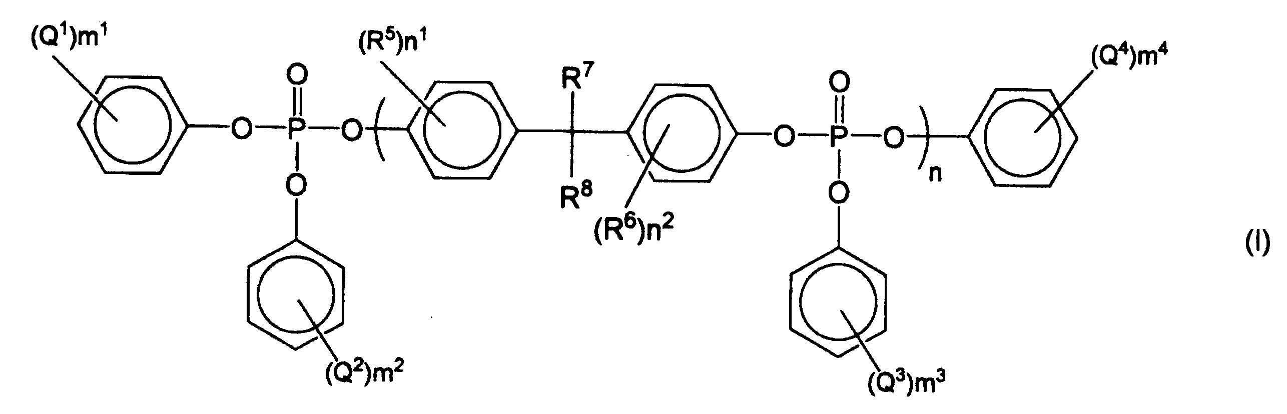
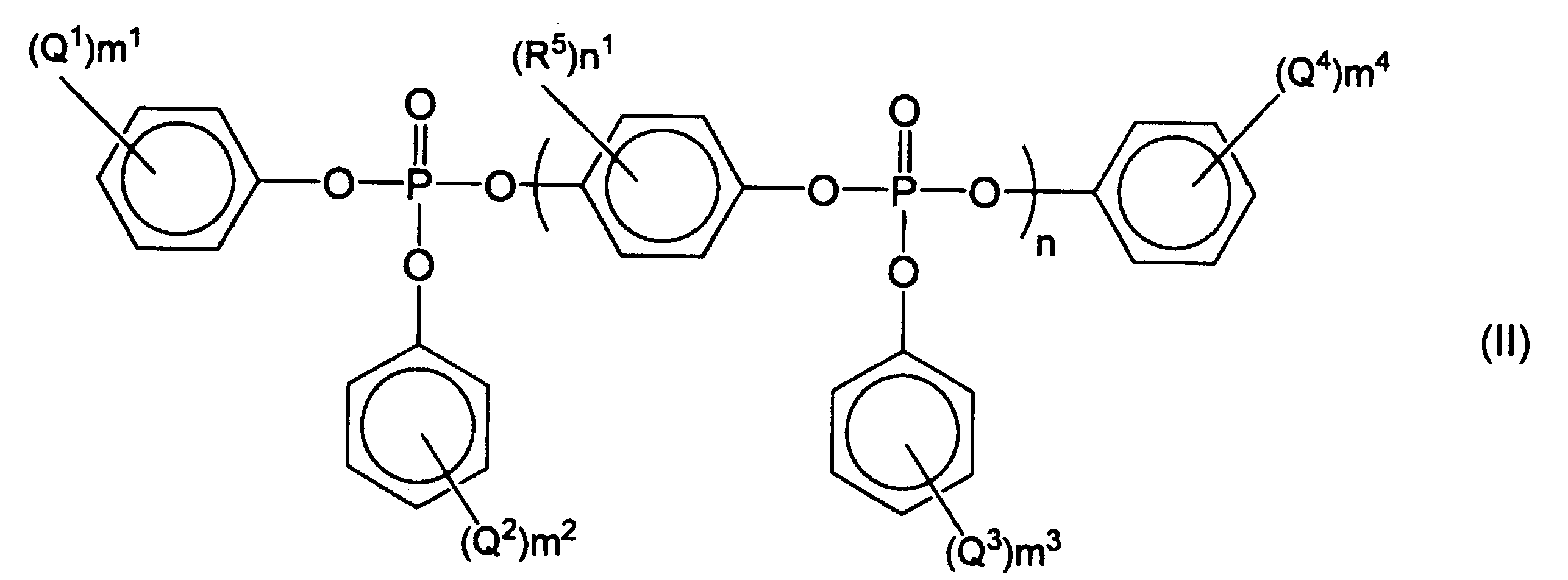
つぎに本実施形態に用いる(c)成分について説明する。(c)成分は、フッ素原子を含有する樹脂(フッ素含有樹脂)であり、難燃樹脂組成物の表面外観を向上させ、難燃樹脂フィルムの成形時の加工性や厚み精度を向上させる効果に寄与するものである。
(1)ポリテトラフルオロエチレンの水性分散液と、有機重合体の水性分散液又は溶液とを混合し、共沈殿を行い共凝集混合物を得る方法(特開昭60-258263号公報、特開昭63-154744号公報などに記載された方法)。
(2)ポリテトラフルオロエチレンの水性分散液と、乾燥した有機重合体粒子とを混合する方法(特開平4-272957号公報に記載された方法)。
(3)ポリテトラフルオロエチレンの水性分散液と、有機重合体粒子溶液とを均一に混合し、かかる混合物からそれぞれの媒体を同時に除去する方法(特開平06-220210号公報、特開平08-188653号公報などに記載された方法)。
(4)ポリテトラフルオロエチレンの水性分散液中で有機重合体を形成する単量体を重合する方法(特開平9-95583号公報に記載された方法)。
(5)ポリテトラフルオロエチレンの水性分散液と有機重合体分散液とを均一に混合後、さらに該混合分散液中でビニル系単量体を重合し、その後混合物を得る方法(特開平11-29679号などに記載された方法)。
本実施形態の難燃樹脂組成物又は本実施形態の難燃樹脂フィルムに用いる樹脂組成物は、フッ素元素含有量が、100~1000質量ppmであり、好ましくは100~800質量ppmであり、さらに好ましくは120~500質量ppmである。
本実施形態の難燃樹脂組成物又は本実施形態の難燃樹脂フィルムに用いる樹脂組成物は、(d)エラストマーをさらに含むことが好ましい。
さらに本実施形態の難燃樹脂組成物又は本実施形態の難燃樹脂フィルムに用いる樹脂組成物には、上記の成分の他に本発明の特徴及び効果を損なわない範囲で必要に応じて他の付加的成分を添加してもかまわない。このような他の成分としては、例えば、酸化防止剤、金属不活性化剤、可塑剤(ミネラルオイル、低分子量ポリエチレン、エポキシ化大豆油、ポリエチレングリコール、脂肪酸エステル類等)、難燃助剤、耐候(光)性改良剤(ベンゾフェノン系紫外線吸収剤、ベンゾトリアゾール系紫外線吸収剤、ヒンダードアミン系光安定剤等)、スリップ剤、無機又は有機の充填材や強化材(ポリアクリロニトリル繊維、アラミド繊維等)、各種着色剤(カーボンブラック、酸化チタン等)、離型剤等が挙げられる。
本実施形態の難燃樹脂組成物の製造方法としては、特に限定されず、例えば、種々の溶融混練機を用いて上記各成分を溶融混練する方法が挙げられる。これらの方法を行う溶融混練機としては、特に限定されず、例えば、単軸押出機、二軸押出機を含む多軸押出機、ロール、ニーダー、ブラベンダープラストグラフ、バンバリーミキサー等による加熱溶融混練機が挙げられる。中でも本実施形態の難燃樹脂組成物の製造方法としては、二軸押出機を用いて上記各成分を溶融混練する方法が好ましい。該二軸押出機の具体例としては、特に限定されなないが、WERNER&PFLEIDERER社製のZSKシリーズ、東芝機械(株)製のTEMシリーズ、日本製鋼所(株)製のTEXシリーズなどが挙げられる。
1.上記した(a)成分の一部又は全量、(c)成分、又は必要に応じて(d)成分を第一供給口より供給し、次いで(a)成分の残量を第二供給口、(b)成分を第三供給口より溶融混練状態下に供給し、さらに溶融混練を続けて行う方法。
2.(a)成分~(c)成分の全量、又は必要に応じて(d)成分の全量を第一供給口より供給し、溶融混練を行う方法。
3.(a)成分、(c)成分を第1原料供給口より供給し、次いで必要に応じて(d)成分を第二供給口、(b)成分を第三供給口より溶融混練状態下に供給し、溶融混練を行う方法等が挙げられる。
本実施形態の難燃樹脂フィルムは、例えば、上述した難燃樹脂組成物を成形することにより製造することができる。
本実施形態の難燃樹脂フィルムの厚みは、20~500μmであり、好ましくは50~250μmである。難燃樹脂フィルムとして使用されるときの機械的強度と加工性(折り曲げ性など)との観点から、難燃樹脂フィルムの厚み下限値は20μm、難燃樹脂フィルムの上限値は500μmである。
本実施形態の難燃樹脂フィルムは、太陽電池バックシートに用いることができる。また耐熱性、難燃性、電気絶縁性等の特性が要求される他の用途にも用いることができる。他の用途としては、例えば、プリント基板材料、プリント基板周辺部品、半導体パッケージ、データ系磁気テープ、APS写真フィルム、フィルムコンデンサー、絶縁フィルム、モーターやトランスなどの絶縁材料、スピーカー振動板、自動車用フィルムセンサー、ワイヤーケーブルの絶縁テープ、TABテープ、発電機スロットライナ層間絶縁材料、トナーアジテーター、リチウムイオン電池などの絶縁ワッシャーなど電子・電気部品材料、家電OA用材料、自動車用材料、工業用材料などの絶縁フィルムに好適に用いることができる。
本実施形態の太陽電池バックシートは、上述の難燃樹脂フィルムを含む。
本実施形態の太陽電池バックシートは、上記難燃樹脂フィルムからなる層のみの単層であってもよいし、2層以上からなる多層構造を有していてもよい。多層構造としては、例えば、上記難燃樹脂フィルムからなる層に、異なる成分の層を1又は2以上積層された構造等が挙げられる。このような多層構造としては、上記難燃樹脂フィルムからなる層と、ガスバリア層とを含む構造であることが好ましく、さらに耐光層を含む構造であることがより好ましい。
本実施形態の太陽電池バックシートは、上記難燃樹脂フィルムからなる層のみの単層である場合には、上記難燃樹脂組成物を原料とし押出フィルム成形することにより得ることもできるし、上記難燃樹脂フィルムを構成する原料成分を押出フィルム成形機に直接投入し、ブレンドとフィルム成形とを同時に実施して得ることもできる。
本実施形態の太陽電池モジュールは、光透過性基板と、封止材層と、太陽電池素子と、上述した太陽電池バックシートと、を含む。
a1:2,6-キシレノールを酸化重合して得たポリフェニレンエーテル(以下「PPE」とも記す。)。該PPEは、還元粘度(0.5g/dl、クロロホルム溶液、30℃測定)が0.50であり、DSC法によるガラス転移点(Tg)が215℃であった。
a2:2,6-キシレノールを酸化重合して得たPPE。該PPEは、還元粘度(0.5g/dl、クロロホルム溶液、30℃測定)が0.40であり、DSC法によるガラス転移点(Tg)が215℃であった。
a3:2,6-キシレノールを酸化重合して得たPPE。該PPEは、還元粘度が0.35であり、DSC法によるガラス転移点(Tg)が213℃であった。
a4:アタクチックポリスチレン(PSジャパン社製、商品名 ポリスチレン685)。
a5:ハイインパクトポリスチレン(PSジャパン社製、商品名 ポリスチレンH9405)。
b1:ビスフェノールAのビスジフェニルホスフェートを主成分とする縮合リン酸エステル(大八化学(株)製、商品名 CR-741)。
c1:ポリテトラフルオロエチレン(ダイキン工業(株)社製、商品名ポリフロン(登録商標)FA-500)。
c2:ポリテトラフルオロエチレン(ダイキン工業(株)社製、商品名ポリフロン(登録商標)FA-500)/ハイインパクトポリスチレン(PSジャパン社製、ポリスチレンH9405)=90質量%/10質量%を、予めニーダーを用いて溶融混練を行って得られたポリテトラフルオロエチレンマスターバッチ。
c3:テトラフルオロエチレン-ヘキサフルオロプロピレン共重合体(ダイキン工業(株)社製、商品名ネオフロン(登録商標)FEP NP-101)。
c4:エチレン-テトラフルオロエチレン共重合体(旭硝子(株)社製、商品名フルオン(登録商標)LM-720AP)。
c5:エチレン-テトラフルオロエチレン共重合体(旭硝子(株)社製、商品名フルオン(登録商標)LM-730AP)。
c6:エチレン-テトラフルオロエチレン共重合体(旭硝子(株)社製、商品名フルオン(登録商標)LM-740AP)。
c7:エチレン-テトラフルオロエチレン共重合体(ダイキン工業(株)社製、商品名ネオフロン(登録商標)ETFE EP-546)。
c8:エチレン-テトラフルオロエチレン共重合体(ダイキン工業(株)社製、商品名ネオフロン(登録商標)ETFE EP-610)。
c9:エチレン-テトラフルオロエチレン-ヘキサフルオロプロピレン共重合体(ダイキン工業(株)社製、商品名ネオフロン(登録商標)EFEP RP-5000)。
d1:ポリスチレン-水素添加されたポリブタジエン-ポリスチレンのブロック構造を持ち、結合スチレン量が35%、数平均分子量が197000、ポリブタジエン部の水素添加率が99.3%の水添ブロック共重合体。
d2:ポリスチレン-水素添加されたポリブタジエン-ポリスチレンのブロック構造を持ち、結合スチレン量が65%、数平均分子量が85000、ポリブタジエン部の水素添加率が99.2%の水添ブロック共重合体。
d3:ポリスチレン-水素添加されたポリブタジエン-ポリスチレンのブロック構造を持ち、結合スチレン量が30%、数平均分子量が61000、ポリブタジエン部の水素添加率が99.4%の水添ブロック共重合体。
各樹脂組成物の製造及び物性評価と、各フィルムの製造及び特性評価とを、以下の方法に従って実施した。
樹脂組成物の製造には、二軸押出機ZSK-40(WERNER&PFLEIDERER社製)を用いた。該二軸押出機において、原料の流れ方向に対し上流側に第1原料供給口、これより下流に第2原料供給口及び第3原料供給口を設け、さらにその下流に真空ベントを設けた。また、第2原料供給口への原料供給方法は、押出機サイド開放口から強制サイドフィーダーを用いて供給する方法とし、第3原料供給口への原料供給方法は、押出機上部開放口からギアポンプを用いて供給する方法とした。さらに押出機の重量式フィーダーから原料が落下するホッパーの空間の上部にガス抜き用の排気管を設置した。またさらに原料供給ラインに窒素ガスを供給した。これらの経路に設置した酸素濃度計(新コスモス電機(株)製 デジタル酸素濃度計XO-326ALA)で酸素濃度を測定し、原料供給口における酸素濃度を1.0体積%未満に制御した。但し、実施例40では第1原料供給口における酸素濃度を1.4体積%とし、実施例49では第1原料供給口における酸素濃度を1.6体積%、第2原料供給口における酸素濃度を2.0体積%とした。また、押出機ダイス部に#120メッシュ(平織り、網目0.132mm)の金網を挟んだ。
上記で得られた樹脂組成物のペレットを用いて以下のとおりフィルムを製造した。フィルムの製造には、シリンダー温度(270~340℃)に設定したスクリュー径65mmのベント付き単軸押出機を用いた。上記樹脂組成物の製造における二軸押出機の場合と同様に、該単軸押出機の原料供給ラインに窒素ガスを供給し、原料供給口における酸素濃度を1.0体積%未満に制御した。但し、実施例41では原料供給口における酸素濃度を1.8体積%とした。詳細な製造条件としては、吐出量60kg/hr、Tダイスリットの厚み0.50mm、ダイスリットの幅650mm、圧延ロール表面温度100~150℃とした。当該製造条件下、引き取り速度を調整し、厚み20~500μmのフィルムを製造した。
得られたフィルムについて、下記(7)~(15)に記載の方法により各特性の評価を行った。当評価結果を併せて表9~16に示す。
(1)押出機金網詰まり(生産性及び収率)
上記の樹脂組成物のペレット製造終了(3時間運転後)毎に押出機ダイス部を開け、上記#120メッシュ(平織り、網目0.132mm)の金網を取り出した。該取り出した金網において、樹脂組成物が通過した金網面に付着していた異物の状態を観察し、押出機金網詰まりについて以下の基準で評価した。
A:金網の目の0%以上10%以下の範囲にフィブリル又はゲル状の異物が付着していた場合。
B:金網の目の10%を超え50%以下の範囲にフィブリル又はゲル状の異物が付着していた場合。
C:金網の目の50%を超えた範囲にフィブリル又はゲル状の異物が付着していた場合。
上記得られた樹脂組成物のペレット中の異物の測定を下記溶解法及びプレス法により行った。
JPCA-ES01-2003記載の方法で、上記得られた樹脂組成物のペレット中のフッ素元素含有量の測定を行った。
上記得られた樹脂組成物のペレットを、220~320℃に設定したスクリューインライン型射出成形機に供給し、金型温度60~90℃の条件で成形し、厚み1.6mm難燃性測定試験片を作成した。UL-94 5thEd.に従い、前記作成した厚み1.6mm難燃性測定試験片を用いてVB試験を行った。
上記得られた樹脂組成物のペレットを用いて、JIS K7152-1及びK7313-2に準拠し、JIS K7139試験片を成形、切削し、シャルピー衝撃強度測定用試験片を作成した。該シャルピー衝撃強度測定用試験片を用いて、JIS K7111-1に準拠しシャルピー衝撃強さを測定した。
上記得られた樹脂組成物のペレットを用いて、両端にランナーを設けたJIS K7139試験片金型でウエルド試験片を作成した。ポリテトラフロロエチレンマスターバッチ添加した樹脂組成物(実施例37)を用いたウエルド試験片におけるウエルド表面外観を基準(B)とし、以下のとおり各ウエルド試験片におけるウエルド表面外観を以下のとおり評価した。
A:ウエルド部の境目が実施例37より目立たなかった場合。
B:ウエルド部の境目が実施例37と同等であった場合。
C:ウエルド部の境目が実施例37より目立っていた場合。
沈殿管(50ml)中で、上記得られたフィルム約1g(W1)をクロロホルム20mlに溶解して溶液を得た。該溶液をシェーカーにて60分間振とうした。該振とう後の溶液を、遠心分離機を用いて遠心分離し、さらにデカンテーションを行って沈殿物を取出した。該沈殿物を160℃、常圧で1時間、真空下でさらに2時間処理し、該沈殿物から溶媒を除去した。該沈殿物から溶媒を除去した残渣物の重量(g)(W2)を測定した。不溶分率の計算は以下のように行った。
サンプル管(50ml)中で、上記得られたフィルム1gをクロロホルム20mlに溶解して溶液を得た。該溶液をシェーカーにて60分間振とうした。該振とう後の溶液を、直径70mmのろ紙(アドバンテック社製 定量ろ紙No.3)で吸引ろ過した。該吸引ろ過後のろ紙を1時間室温で風乾し、該ろ紙上における最大径10μm以上の異物の数を測定した。このとき、クロロホルム不溶分(ゲル状物質)が多く、ろ紙でろ過出来なかった場合を「測定不能」とした。
UL-94 5thEd.に従い、上記得られたフィルムを用いてVTM試験を行った。ただし、上記得られたフィルムのうち、厚みが400μm以上のフィルムの場合、試験片作成(シートを丸めること)が困難なため、VB試験を行った。また、場合により、厚みが400μm以上のフィルムを製造した樹脂組成物と同様の組成の樹脂組成物を用いて厚み60μmのフィルムを製造し、得られたフィルムについてVTM試験を行った。
上記得られたフィルムにおける樹脂組成物成分のガラス転移温度を、Perkin-Elmer社製DSC測定機によって測定した。該測定において、温度範囲を50℃から300℃とし、雰囲気を窒素雰囲気とし、昇温速度を20℃/分とした。
上記得られたフィルムを、100mm×100mmのサイズにカットして各試験片を作製した。各試験片のMD方向の寸法をマイクロメーターで測定した。次に、JIS-C2318に準拠し、各試験片を150℃の熱オーブン中に30分間静置し加熱収縮させ、23℃、50%RHに制御した実験室に24時間放置した。その後、各試験片のMD方向の寸法を再度マイクロメーターで測定した。各試験片の加熱収縮前後のMD方向の寸法変化(収縮率)を算出した。このとき、フィルムの変形が大きく正確な寸法測定が出来ない場合を「測定不能」とした。
上記得られた所定厚みのフィルムの両端を切り、幅300×長さ500mmのフィルムを作成した。このフィルムの四隅及びその中間からフィルムの中心に向かい20mmの場所の厚みをマイクロゲージ(株式会社ミツトヨ製デジマチックインジケーターID-C112BS)にて測定(計8箇所)し、フィルムの厚みの標準偏差を算出した。該標準偏差が小さいほど、厚み精度に優れると評価した。
上記フィルムの製造において、Tダイリップをワイピングし、3時間フィルム引取りを行った後、リップに付着した目ヤニを観察し、表面外観(目ヤニ、ダイライン)を下記基準により評価とした。
A:目ヤニ発生がなかった場合。
B:フィルムに殆どダイラインは観察されなかったが、目ヤニが発生した場合。
C:フィルムにダイラインが顕著に観察されるほど目ヤニ発生が多かった場合。
上記得られたフィルムについて、JIS-Z8741に準じた方法でデジタル変角光沢計(日本電色工業製:VGS-1D型)を用いて入射光反射光変角60°の光沢度を測定した。該測定値に基づき下記の基準によりフィルムの表面外観(光沢)を評価した。
AA:光沢度95%以上。
A:光沢度70%以上~95%未満。
B:光沢度60%以上~70%未満。
C:光沢度60%未満。
厚み5mm透明ガラス板と、封止材として厚み500μmのエチレン-酢酸ビニル共重合体(ETIMEX製、VISTRASOLAR)と、さらに上記得られたフィルムとを、縦100mm、横50mmの寸法で、この順番に積層し、150℃で30分間減圧下で熱プレスし、バックシート加工性を下記の基準により評価した。
A:フィルムと封止材との間にボイドが観察されず、フィルムと封止材とが密着した場合。
B:フィルムと封止材との間にボイドが観察された場合。
C:フィルムが融けた状態で変形した場合。

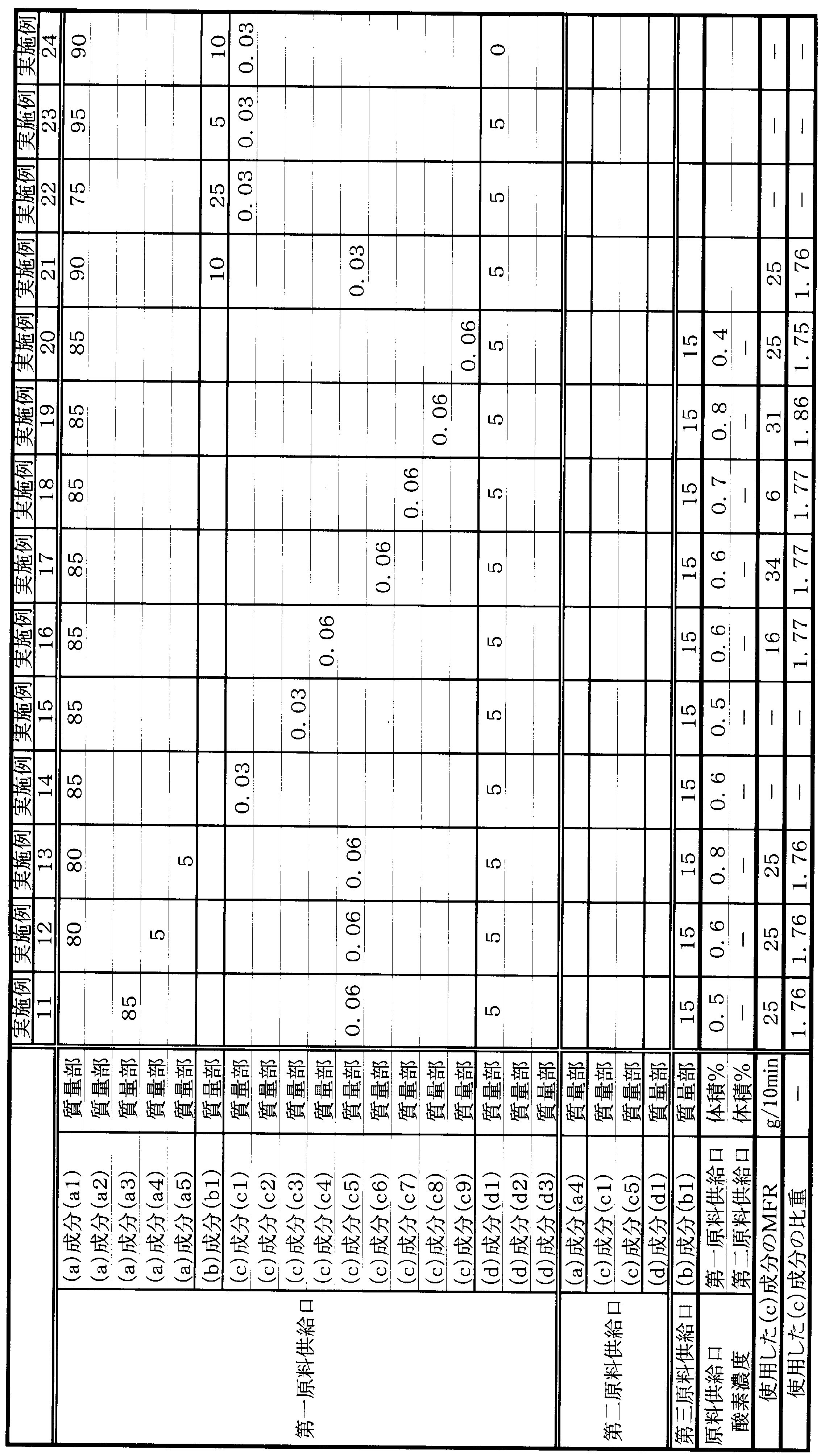


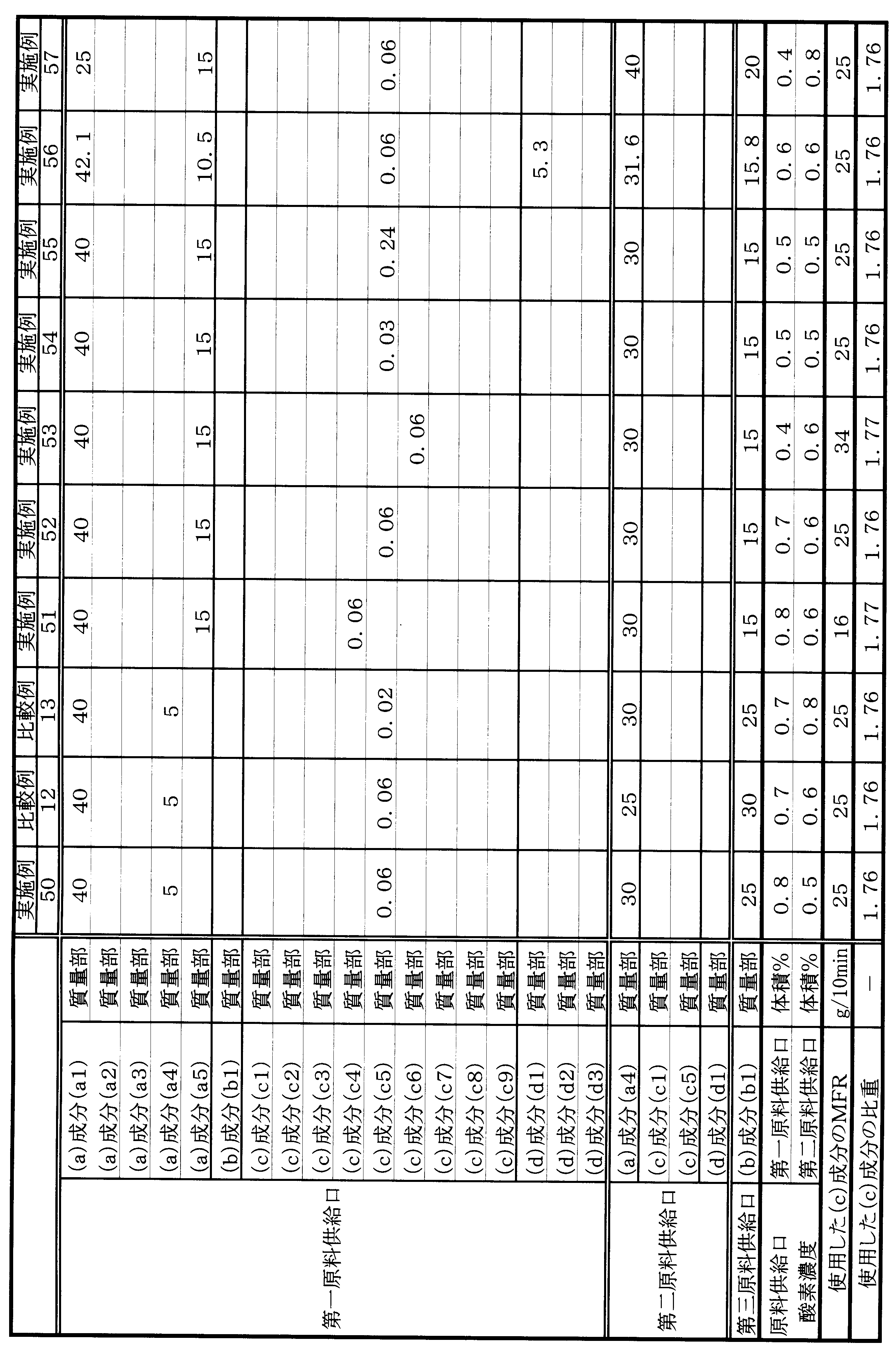
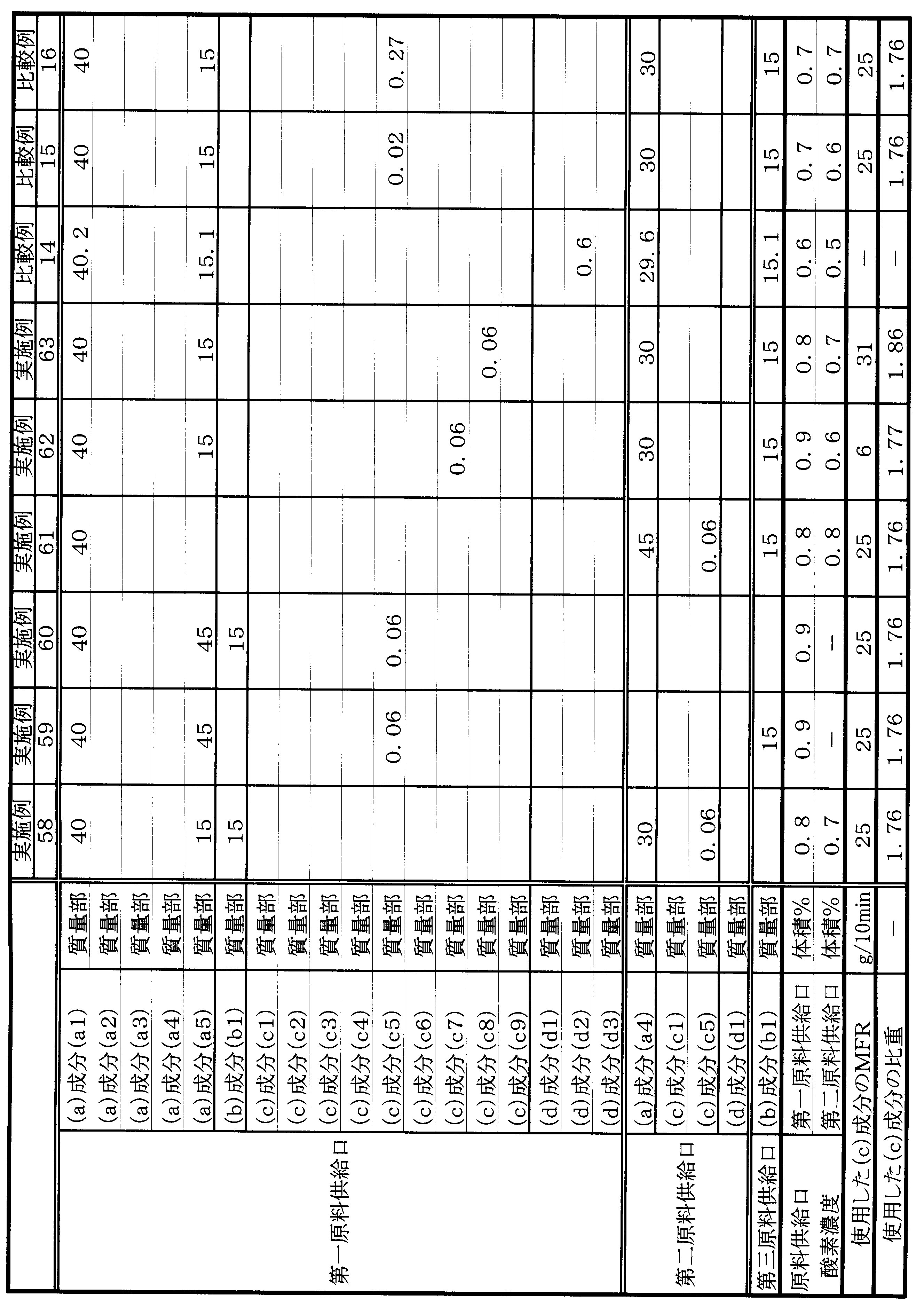
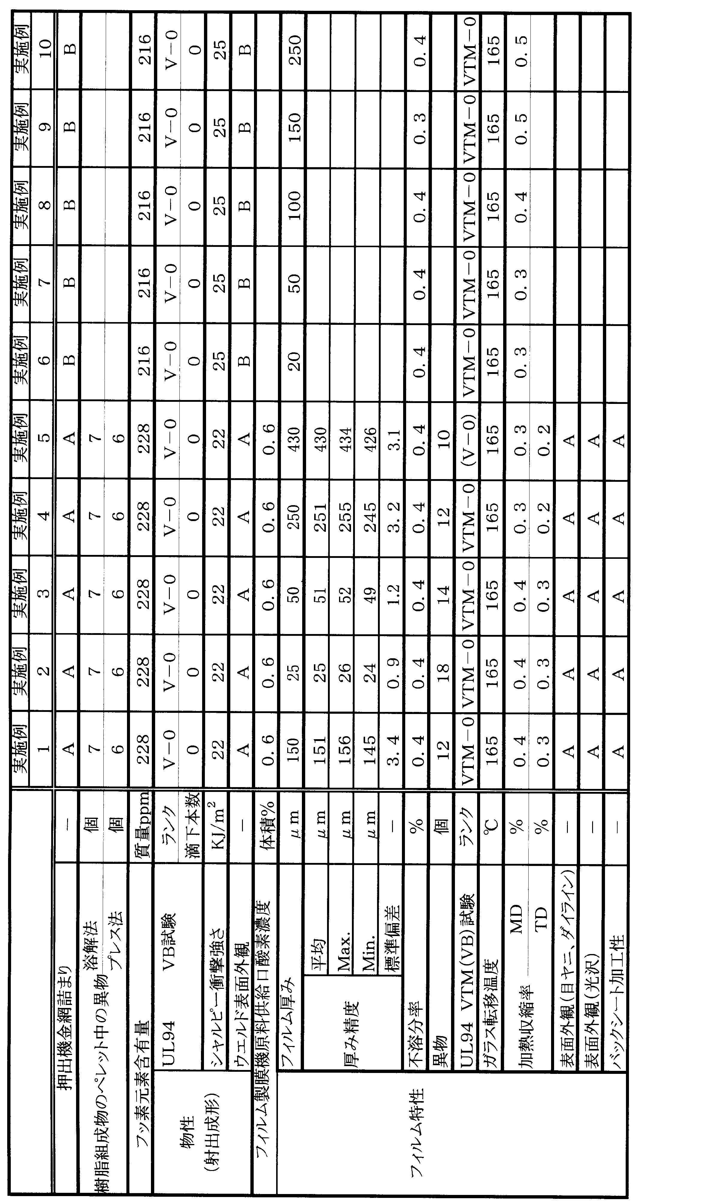


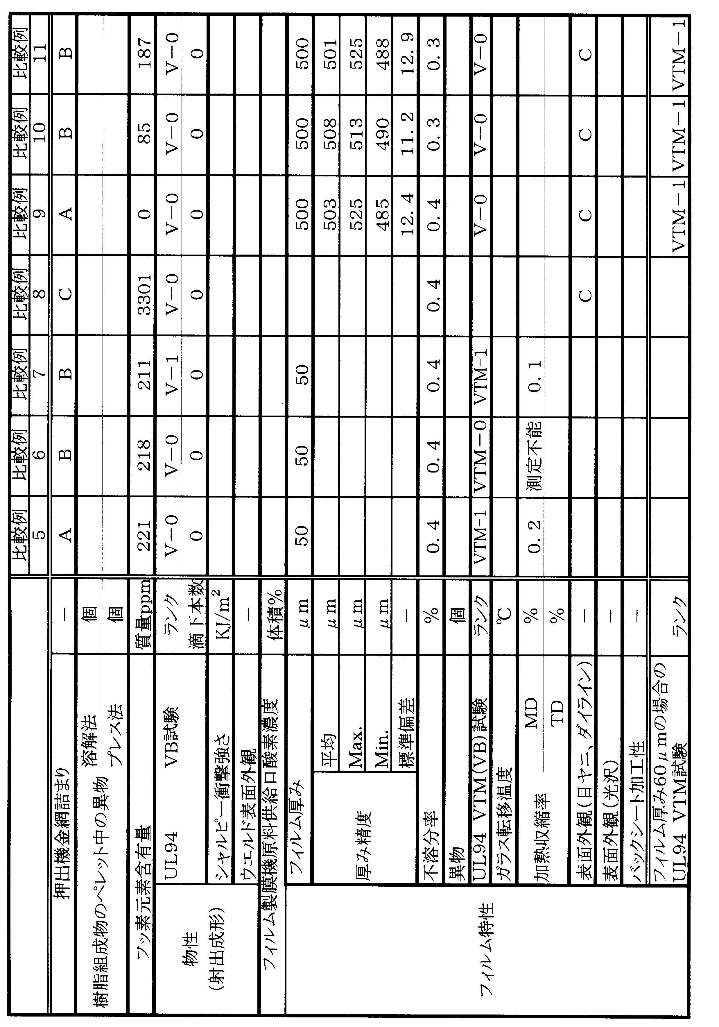
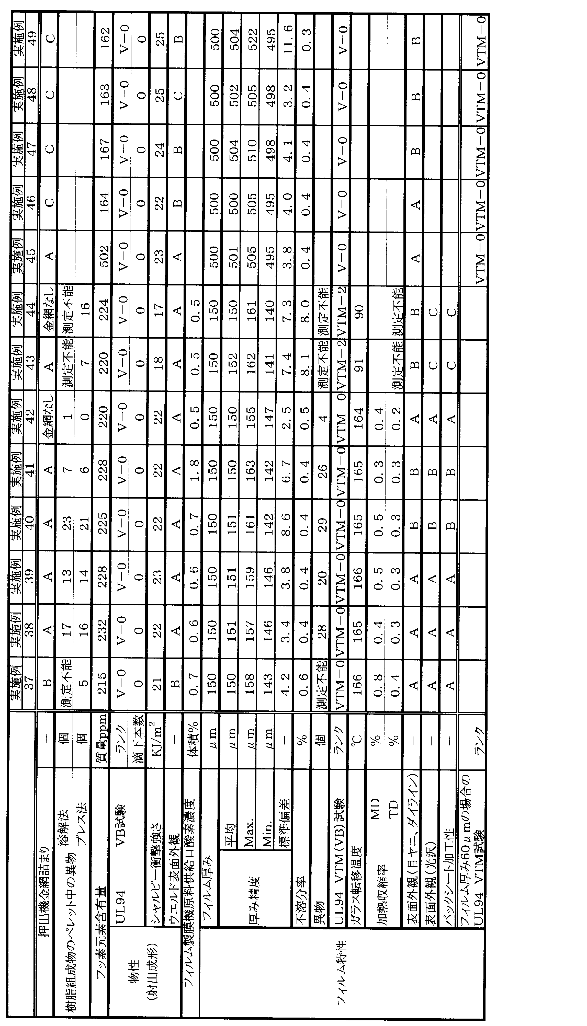

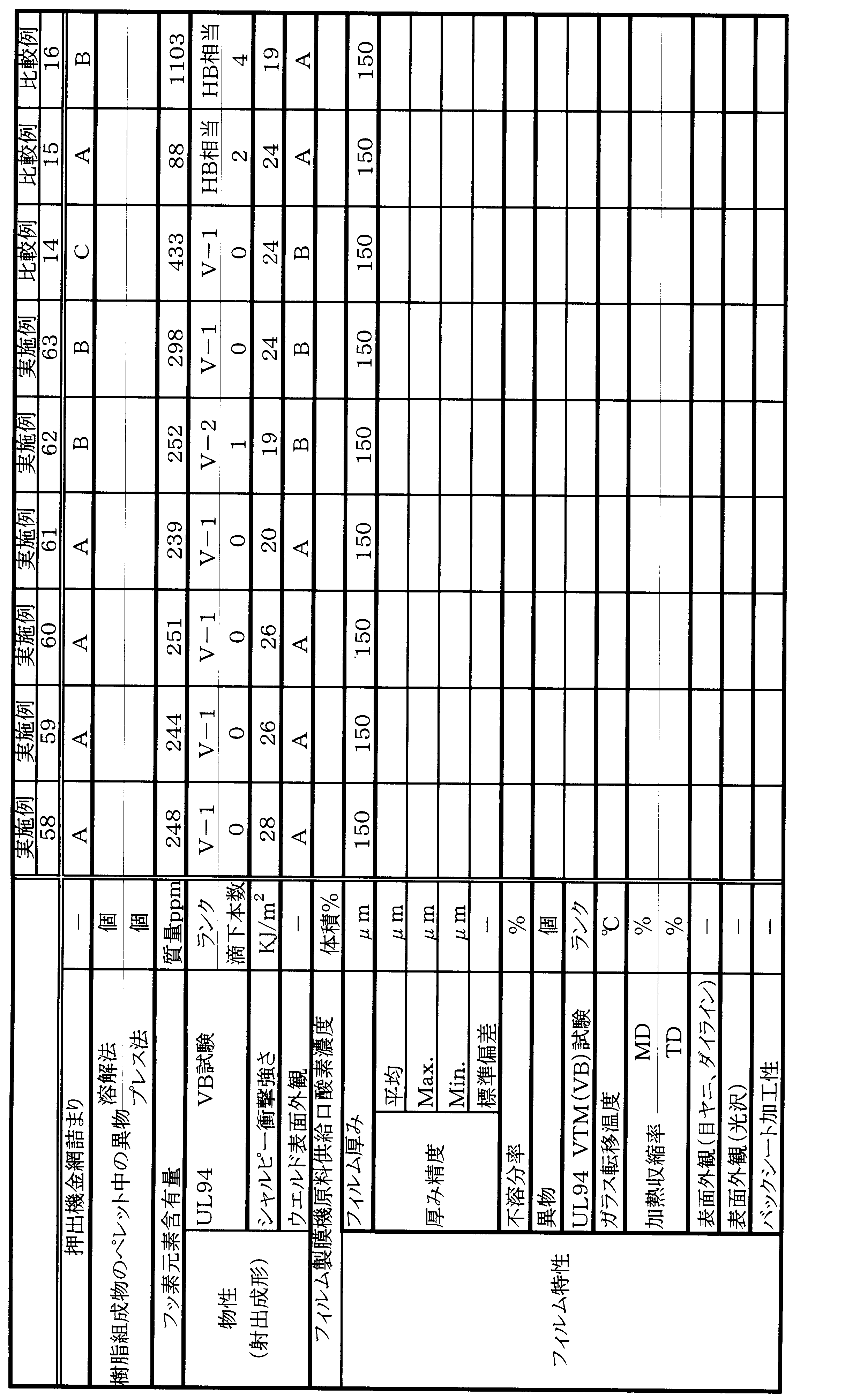
Claims (10)
- 樹脂組成物から得られる難燃樹脂フィルムであって、
前記樹脂組成物が、(a)ポリフェニレンエーテル系樹脂、(b)リン系難燃剤及び(c)フッ素含有樹脂を含み、
前記樹脂組成物において、前記(a)及び(b)成分の合計100質量部に対して、(a)成分の含有量が75~98質量部、(b)成分の含有量が25~2質量部であり、
前記樹脂組成物中のフッ素元素含有量が100~1000質量ppmであり、
厚みが20~500μmである難燃樹脂フィルム。 - 前記(c)成分のフッ素含有樹脂がオレフィン-フルオロエチレン共重合体である請求項1に記載の難燃樹脂フィルム。
- 前記(c)成分のオレフィン-フルオロエチレン共重合体がエチレン-テトラフルオロエチレン共重合体である請求項2に記載の難燃樹脂フィルム。
- 前記(c)成分のフッ素含有樹脂がポリテトラフルオロエチレンである請求項1に記載の難燃樹脂フィルム。
- 前記樹脂組成物が、(d)エラストマーをさらに含み、
前記樹脂組成物において、前記(a)及び(b)成分の合計100質量部に対して、(d)成分の含有量が1~25質量部である請求項1~4のいずれか一項に記載の難燃樹脂フィルム。 - 請求項1~5のいずれか一項に記載の難燃樹脂フィルムを含む太陽電池バックシート。
- (a)ポリフェニレンエーテル系樹脂、(b)リン酸エステル系難燃剤及び(c)エチレン-テトラフルオロエチレン共重合体を含み、
前記(a)及び(b)成分の合計100質量部に対して、(a)成分の含有量が75~98質量部、(b)成分の含有量が25~2質量部であり、
フッ素元素含有量が100~1000質量ppmである難燃樹脂組成物。 - (d)エラストマーをさらに含み、
前記(a)及び(b)成分の合計100質量部に対して、(d)成分の含有量が1~25質量部である請求項7に記載の難燃樹脂組成物。 - 請求項7又は8に記載の難燃樹脂組成物を含む樹脂ペレット。
- 請求項7又は8に記載の難燃樹脂組成物を含む射出成形品。
Priority Applications (4)
| Application Number | Priority Date | Filing Date | Title |
|---|---|---|---|
| EP12788767.7A EP2712892B1 (en) | 2011-05-20 | 2012-05-18 | Flame-retardant resin film and solar cell backsheet using same |
| US14/118,577 US9587102B2 (en) | 2011-05-20 | 2012-05-18 | Flame-retardant resin film and solar battery back sheet using the same |
| CN201280022379.5A CN103517949B (zh) | 2011-05-20 | 2012-05-18 | 阻燃树脂膜和使用其的太阳能电池背板 |
| JP2013516353A JP5905877B2 (ja) | 2011-05-20 | 2012-05-18 | 難燃樹脂フィルム及びそれを用いた太陽電池バックシート |
Applications Claiming Priority (6)
| Application Number | Priority Date | Filing Date | Title |
|---|---|---|---|
| JP2011113503 | 2011-05-20 | ||
| JP2011113501 | 2011-05-20 | ||
| JP2011-113501 | 2011-05-20 | ||
| JP2011-113503 | 2011-05-20 | ||
| JP2012036569 | 2012-02-22 | ||
| JP2012-036569 | 2012-02-22 |
Publications (1)
| Publication Number | Publication Date |
|---|---|
| WO2012161134A1 true WO2012161134A1 (ja) | 2012-11-29 |
Family
ID=47217211
Family Applications (1)
| Application Number | Title | Priority Date | Filing Date |
|---|---|---|---|
| PCT/JP2012/062852 WO2012161134A1 (ja) | 2011-05-20 | 2012-05-18 | 難燃樹脂フィルム及びそれを用いた太陽電池バックシート |
Country Status (6)
| Country | Link |
|---|---|
| US (1) | US9587102B2 (ja) |
| EP (1) | EP2712892B1 (ja) |
| JP (2) | JP5905877B2 (ja) |
| CN (1) | CN103517949B (ja) |
| TW (1) | TWI461469B (ja) |
| WO (1) | WO2012161134A1 (ja) |
Cited By (5)
| Publication number | Priority date | Publication date | Assignee | Title |
|---|---|---|---|---|
| WO2015002145A1 (ja) * | 2013-07-05 | 2015-01-08 | 旭化成ケミカルズ株式会社 | 絶縁樹脂成形体を具備する電気部品、及び難燃性の安定化方法 |
| US20150064437A1 (en) * | 2013-08-27 | 2015-03-05 | Ticona Llc | Heat resistant toughened thermoplastic composition for injection molding |
| JP2015044962A (ja) * | 2013-08-29 | 2015-03-12 | 旭化成ケミカルズ株式会社 | 樹脂組成物 |
| JP2016037536A (ja) * | 2014-08-06 | 2016-03-22 | 旭化成ケミカルズ株式会社 | 難燃樹脂組成物及びその製造方法 |
| US10263225B2 (en) | 2013-06-26 | 2019-04-16 | Mitsubishi Gas Chemical Company, Inc. | Flame-retardant sheet or film, products comprising the same and process for production thereof |
Families Citing this family (10)
| Publication number | Priority date | Publication date | Assignee | Title |
|---|---|---|---|---|
| JP6657950B2 (ja) * | 2014-08-13 | 2020-03-04 | 三菱ケミカル株式会社 | 積層フィルム、積層成形品及びその製造方法 |
| CN104538473B (zh) * | 2014-12-25 | 2017-02-01 | 杭州福斯特光伏材料股份有限公司 | 一种太阳能电池组件用阻燃背板 |
| US10707526B2 (en) | 2015-03-27 | 2020-07-07 | New Dominion Enterprises Inc. | All-inorganic solvents for electrolytes |
| CN106634647A (zh) * | 2015-10-28 | 2017-05-10 | 阿特斯(中国)投资有限公司 | 一种太阳能光伏阻燃型白色eva封装胶膜及阻燃型双玻光伏组件 |
| US10707531B1 (en) | 2016-09-27 | 2020-07-07 | New Dominion Enterprises Inc. | All-inorganic solvents for electrolytes |
| CN110114216B (zh) | 2016-12-28 | 2021-09-14 | 沙特基础工业全球技术有限公司 | 包含聚亚苯基化物和聚丙烯的多层片材及其制造方法 |
| KR102459767B1 (ko) | 2016-12-28 | 2022-10-26 | 사빅 글로벌 테크놀러지스 비.브이. | 폴리페닐렌 및 아릴 살리실레이트를 포함하는 시트, 및 이의 제조 방법 |
| WO2019026689A1 (ja) * | 2017-08-03 | 2019-02-07 | 三菱エンジニアリングプラスチックス株式会社 | 樹脂組成物、成形品および電線 |
| JP6990571B2 (ja) * | 2017-12-12 | 2022-01-12 | 旭化成株式会社 | 樹脂組成物、樹脂組成物の製造方法、及び成形体 |
| WO2019188255A1 (ja) * | 2018-03-26 | 2019-10-03 | リンテック株式会社 | 樹脂シートおよびその製造方法 |
Citations (29)
| Publication number | Priority date | Publication date | Assignee | Title |
|---|---|---|---|---|
| US2393697A (en) | 1941-08-01 | 1946-01-29 | Pantex Pressing Machine Inc | Pressing head for pressing machines and method of its manufacture |
| US2534058A (en) | 1946-11-30 | 1950-12-12 | Du Pont | Polymerization of tetrafluoroethylene with dibasic acid peroxide catalysts |
| US3257358A (en) | 1963-07-02 | 1966-06-21 | Du Pont | 2, 6-dichloro-1, 4-polyphenylene ether |
| US3257357A (en) | 1963-04-01 | 1966-06-21 | Du Pont | Copolymers of polyphenylene ethers |
| US3306874A (en) | 1962-07-24 | 1967-02-28 | Gen Electric | Oxidation of phenols |
| US3306875A (en) | 1962-07-24 | 1967-02-28 | Gen Electric | Oxidation of phenols and resulting products |
| JPS5051197A (ja) | 1973-09-06 | 1975-05-07 | ||
| JPS5217880A (en) | 1975-07-31 | 1977-02-10 | Mitsubishi Heavy Ind Ltd | Method to walk inside tube |
| JPS58164634A (ja) * | 1982-02-08 | 1983-09-29 | ゼネラル・エレクトリツク・カンパニイ | Ppe、衝撃改良剤、無機充填剤及びptfeよりなる組成物 |
| JPS60258263A (ja) | 1984-05-29 | 1985-12-20 | バイエル・アクチエンゲゼルシヤフト | テトラフルオロエチレン重合体を含む重合体粉末混合物の製造方法 |
| JPS63152628A (ja) | 1986-12-17 | 1988-06-25 | Asahi Chem Ind Co Ltd | 色調の優れたポリフエニレンエ−テル系樹脂の製造法 |
| JPS63154744A (ja) | 1986-12-02 | 1988-06-28 | モベイ・コーポレーシヨン | ポリカーボネートにフルオロポリマーを混入する方法 |
| JPH04272957A (ja) | 1990-10-31 | 1992-09-29 | General Electric Co <Ge> | 改良された外観及び改良された難燃性をもつポリカーボネート |
| JPH06220210A (ja) | 1992-11-17 | 1994-08-09 | General Electric Co <Ge> | 固体の添加剤をポリマー性樹脂に分散させる方法 |
| JPH08188653A (ja) | 1995-01-10 | 1996-07-23 | General Electric Co <Ge> | 固体の添加剤をポリマー中に分散させる方法およびそれによって得られる製品 |
| JPH0995583A (ja) | 1995-04-28 | 1997-04-08 | General Electric Co <Ge> | テトラフルオロエチレン誘導体の群を含んでなる重合物を基体とする新規ポリマーブレンド、該ブレンドの製造法と該ブレンドから得られる製品並びに該ブレンドのポリマー組成物における使用 |
| JPH115879A (ja) | 1997-06-17 | 1999-01-12 | Asahi Chem Ind Co Ltd | フッ素系樹脂含有滴下型難燃樹脂組成物 |
| JPH1129679A (ja) | 1996-07-31 | 1999-02-02 | Mitsubishi Rayon Co Ltd | ポリテトラフルオロエチレン含有混合粉体、その製造方法、それを含む熱可塑性樹脂組成物およびその成形体 |
| JPH11209601A (ja) * | 1998-01-22 | 1999-08-03 | Asahi Chem Ind Co Ltd | 滴下防止性能に優れたポリフェニレンエーテル系難燃樹脂組成物 |
| JP2000309700A (ja) * | 1999-04-27 | 2000-11-07 | Asahi Chem Ind Co Ltd | ポリフェニレンエーテル系樹脂組成物の製造方法 |
| JP2001207072A (ja) * | 1999-11-15 | 2001-07-31 | Daicel Chem Ind Ltd | 難燃性樹脂組成物 |
| JP2004292660A (ja) * | 2003-03-27 | 2004-10-21 | Asahi Kasei Chemicals Corp | 熱可塑性樹脂組成物 |
| JP2006324556A (ja) | 2005-05-20 | 2006-11-30 | Toppan Printing Co Ltd | 太陽電池用バックシートおよびそれを用いた太陽電池モジュール |
| WO2006126670A1 (ja) * | 2005-05-26 | 2006-11-30 | Kaneka Corporation | 難燃性樹脂組成物 |
| JP2007070430A (ja) | 2005-09-06 | 2007-03-22 | Toray Ind Inc | 太陽電池用ポリエステルフィルム |
| JP2010519389A (ja) | 2007-02-23 | 2010-06-03 | サビック イノベーティブ プラスチックス イーペー ベスローテン フェンノートシャップ | 電気絶縁フィルムおよびその製法 |
| JP2010195935A (ja) | 2009-02-25 | 2010-09-09 | Teijin Chem Ltd | 難燃性樹脂組成物 |
| JP2010245380A (ja) | 2009-04-08 | 2010-10-28 | Asahi Kasei Chemicals Corp | 太陽電池バックシート用フィルム及びそれを用いた太陽電池バックシート並びに太陽電池モジュール |
| JP2010278428A (ja) | 2009-04-30 | 2010-12-09 | Mitsubishi Plastics Inc | 太陽電池用シート及び太陽電池モジュール |
Family Cites Families (8)
| Publication number | Priority date | Publication date | Assignee | Title |
|---|---|---|---|---|
| US4355126A (en) * | 1974-12-06 | 1982-10-19 | General Electric Company | Flame retardant, non-dripping compositions of polyphenylene ether and acrylonitrile-butadiene-styrene |
| US4532281A (en) | 1982-02-08 | 1985-07-30 | General Electric Company | Mineral filled polyphenylene ether resin compositions containing polytetrafluoroethylene resin |
| US5449721A (en) * | 1993-09-08 | 1995-09-12 | Sumitomo Chemical Co., Ltd. | Thermoplastic resin compositions comprising polyphenylene ether, polyamide and fluorocarbon resins |
| ATE548426T1 (de) * | 2001-11-30 | 2012-03-15 | Polyplastics Co | Flammwidrige harzzusammensetzung |
| WO2006012670A1 (en) * | 2004-08-06 | 2006-02-09 | Tristano Pty Ltd | Habitat structure for aquatic animals |
| CN101218305B (zh) | 2005-07-08 | 2011-03-23 | 宝理塑料株式会社 | 阻燃性树脂组合物 |
| JP5474371B2 (ja) * | 2009-02-20 | 2014-04-16 | オリンパス株式会社 | 熱可塑性樹脂組成物、並びに医療製品及び内視鏡操作部 |
| KR20120003004A (ko) * | 2009-04-30 | 2012-01-09 | 미쓰비시 쥬시 가부시끼가이샤 | 태양 전지용 시트 및 태양 전지 모듈 |
-
2012
- 2012-05-18 EP EP12788767.7A patent/EP2712892B1/en active Active
- 2012-05-18 CN CN201280022379.5A patent/CN103517949B/zh active Active
- 2012-05-18 US US14/118,577 patent/US9587102B2/en active Active
- 2012-05-18 WO PCT/JP2012/062852 patent/WO2012161134A1/ja active Application Filing
- 2012-05-18 JP JP2013516353A patent/JP5905877B2/ja active Active
- 2012-05-21 TW TW101118059A patent/TWI461469B/zh active
-
2016
- 2016-01-22 JP JP2016010461A patent/JP6026025B2/ja active Active
Patent Citations (29)
| Publication number | Priority date | Publication date | Assignee | Title |
|---|---|---|---|---|
| US2393697A (en) | 1941-08-01 | 1946-01-29 | Pantex Pressing Machine Inc | Pressing head for pressing machines and method of its manufacture |
| US2534058A (en) | 1946-11-30 | 1950-12-12 | Du Pont | Polymerization of tetrafluoroethylene with dibasic acid peroxide catalysts |
| US3306874A (en) | 1962-07-24 | 1967-02-28 | Gen Electric | Oxidation of phenols |
| US3306875A (en) | 1962-07-24 | 1967-02-28 | Gen Electric | Oxidation of phenols and resulting products |
| US3257357A (en) | 1963-04-01 | 1966-06-21 | Du Pont | Copolymers of polyphenylene ethers |
| US3257358A (en) | 1963-07-02 | 1966-06-21 | Du Pont | 2, 6-dichloro-1, 4-polyphenylene ether |
| JPS5051197A (ja) | 1973-09-06 | 1975-05-07 | ||
| JPS5217880A (en) | 1975-07-31 | 1977-02-10 | Mitsubishi Heavy Ind Ltd | Method to walk inside tube |
| JPS58164634A (ja) * | 1982-02-08 | 1983-09-29 | ゼネラル・エレクトリツク・カンパニイ | Ppe、衝撃改良剤、無機充填剤及びptfeよりなる組成物 |
| JPS60258263A (ja) | 1984-05-29 | 1985-12-20 | バイエル・アクチエンゲゼルシヤフト | テトラフルオロエチレン重合体を含む重合体粉末混合物の製造方法 |
| JPS63154744A (ja) | 1986-12-02 | 1988-06-28 | モベイ・コーポレーシヨン | ポリカーボネートにフルオロポリマーを混入する方法 |
| JPS63152628A (ja) | 1986-12-17 | 1988-06-25 | Asahi Chem Ind Co Ltd | 色調の優れたポリフエニレンエ−テル系樹脂の製造法 |
| JPH04272957A (ja) | 1990-10-31 | 1992-09-29 | General Electric Co <Ge> | 改良された外観及び改良された難燃性をもつポリカーボネート |
| JPH06220210A (ja) | 1992-11-17 | 1994-08-09 | General Electric Co <Ge> | 固体の添加剤をポリマー性樹脂に分散させる方法 |
| JPH08188653A (ja) | 1995-01-10 | 1996-07-23 | General Electric Co <Ge> | 固体の添加剤をポリマー中に分散させる方法およびそれによって得られる製品 |
| JPH0995583A (ja) | 1995-04-28 | 1997-04-08 | General Electric Co <Ge> | テトラフルオロエチレン誘導体の群を含んでなる重合物を基体とする新規ポリマーブレンド、該ブレンドの製造法と該ブレンドから得られる製品並びに該ブレンドのポリマー組成物における使用 |
| JPH1129679A (ja) | 1996-07-31 | 1999-02-02 | Mitsubishi Rayon Co Ltd | ポリテトラフルオロエチレン含有混合粉体、その製造方法、それを含む熱可塑性樹脂組成物およびその成形体 |
| JPH115879A (ja) | 1997-06-17 | 1999-01-12 | Asahi Chem Ind Co Ltd | フッ素系樹脂含有滴下型難燃樹脂組成物 |
| JPH11209601A (ja) * | 1998-01-22 | 1999-08-03 | Asahi Chem Ind Co Ltd | 滴下防止性能に優れたポリフェニレンエーテル系難燃樹脂組成物 |
| JP2000309700A (ja) * | 1999-04-27 | 2000-11-07 | Asahi Chem Ind Co Ltd | ポリフェニレンエーテル系樹脂組成物の製造方法 |
| JP2001207072A (ja) * | 1999-11-15 | 2001-07-31 | Daicel Chem Ind Ltd | 難燃性樹脂組成物 |
| JP2004292660A (ja) * | 2003-03-27 | 2004-10-21 | Asahi Kasei Chemicals Corp | 熱可塑性樹脂組成物 |
| JP2006324556A (ja) | 2005-05-20 | 2006-11-30 | Toppan Printing Co Ltd | 太陽電池用バックシートおよびそれを用いた太陽電池モジュール |
| WO2006126670A1 (ja) * | 2005-05-26 | 2006-11-30 | Kaneka Corporation | 難燃性樹脂組成物 |
| JP2007070430A (ja) | 2005-09-06 | 2007-03-22 | Toray Ind Inc | 太陽電池用ポリエステルフィルム |
| JP2010519389A (ja) | 2007-02-23 | 2010-06-03 | サビック イノベーティブ プラスチックス イーペー ベスローテン フェンノートシャップ | 電気絶縁フィルムおよびその製法 |
| JP2010195935A (ja) | 2009-02-25 | 2010-09-09 | Teijin Chem Ltd | 難燃性樹脂組成物 |
| JP2010245380A (ja) | 2009-04-08 | 2010-10-28 | Asahi Kasei Chemicals Corp | 太陽電池バックシート用フィルム及びそれを用いた太陽電池バックシート並びに太陽電池モジュール |
| JP2010278428A (ja) | 2009-04-30 | 2010-12-09 | Mitsubishi Plastics Inc | 太陽電池用シート及び太陽電池モジュール |
Non-Patent Citations (1)
| Title |
|---|
| See also references of EP2712892A4 * |
Cited By (9)
| Publication number | Priority date | Publication date | Assignee | Title |
|---|---|---|---|---|
| US10263225B2 (en) | 2013-06-26 | 2019-04-16 | Mitsubishi Gas Chemical Company, Inc. | Flame-retardant sheet or film, products comprising the same and process for production thereof |
| WO2015002145A1 (ja) * | 2013-07-05 | 2015-01-08 | 旭化成ケミカルズ株式会社 | 絶縁樹脂成形体を具備する電気部品、及び難燃性の安定化方法 |
| CN105340024A (zh) * | 2013-07-05 | 2016-02-17 | 旭化成化学株式会社 | 具备绝缘树脂成型体的电气部件以及阻燃性的稳定化方法 |
| JPWO2015002145A1 (ja) * | 2013-07-05 | 2017-02-23 | 旭化成株式会社 | 絶縁樹脂成形体を具備する電気部品、及び難燃性の安定化方法 |
| US9991622B2 (en) | 2013-07-05 | 2018-06-05 | Asahi Kasei Chemicals Corporation | Electrical component comprising insulating resin molded article, and method for stabilizing flame retardance |
| US20150064437A1 (en) * | 2013-08-27 | 2015-03-05 | Ticona Llc | Heat resistant toughened thermoplastic composition for injection molding |
| US9718225B2 (en) * | 2013-08-27 | 2017-08-01 | Ticona Llc | Heat resistant toughened thermoplastic composition for injection molding |
| JP2015044962A (ja) * | 2013-08-29 | 2015-03-12 | 旭化成ケミカルズ株式会社 | 樹脂組成物 |
| JP2016037536A (ja) * | 2014-08-06 | 2016-03-22 | 旭化成ケミカルズ株式会社 | 難燃樹脂組成物及びその製造方法 |
Also Published As
| Publication number | Publication date |
|---|---|
| JPWO2012161134A1 (ja) | 2014-07-31 |
| TWI461469B (zh) | 2014-11-21 |
| US20140230887A1 (en) | 2014-08-21 |
| EP2712892B1 (en) | 2017-08-02 |
| CN103517949A (zh) | 2014-01-15 |
| TW201307445A (zh) | 2013-02-16 |
| JP6026025B2 (ja) | 2016-11-16 |
| CN103517949B (zh) | 2015-12-02 |
| EP2712892A4 (en) | 2015-07-01 |
| JP5905877B2 (ja) | 2016-04-20 |
| EP2712892A1 (en) | 2014-04-02 |
| JP2016102217A (ja) | 2016-06-02 |
| US9587102B2 (en) | 2017-03-07 |
Similar Documents
| Publication | Publication Date | Title |
|---|---|---|
| JP6026025B2 (ja) | 難燃樹脂フィルム及びそれを用いた太陽電池バックシート | |
| US7550534B2 (en) | Thermoplastic method, composition, and article | |
| US20100240813A1 (en) | Thermoplastic resin composition, and molded product and sheet comprising the composition | |
| KR101768507B1 (ko) | 광전지 연결 박스 및 커넥터용 성형 조성물 | |
| JP2013170258A (ja) | 難燃樹脂フィルム | |
| EP2617772A1 (en) | Polyphenylene ether resin composition and molded article of same | |
| KR101873949B1 (ko) | 미립자-프리 폴리(페닐렌 에테르) 조성물 및 이로부터 유래되는 광전지 백시트 물질의 제조 방법 | |
| JP7097167B2 (ja) | 熱可塑性樹脂組成物、太陽光発電モジュール用接続構造体 | |
| EP2714803A2 (en) | Impact-resistant poly(arylene ether) resins with improved clarity | |
| EP3083815B1 (en) | Polyolefin composition with poly(phenylene ether) filler and article thereof | |
| WO2017208945A1 (ja) | 樹脂組成物、樹脂組成物の製造方法及び成形体 | |
| JP2010245380A (ja) | 太陽電池バックシート用フィルム及びそれを用いた太陽電池バックシート並びに太陽電池モジュール | |
| JP2017214491A (ja) | 樹脂組成物及び成形体 | |
| JP5787449B2 (ja) | 樹脂組成物及び成形品 | |
| CN108117738B (zh) | 树脂组合物 | |
| CN108084691B (zh) | 树脂组合物 | |
| JP7032163B2 (ja) | 樹脂組成物、樹脂組成物の製造方法及び成形体 | |
| JP4804165B2 (ja) | 樹脂製シートの製造方法 | |
| JP4749205B2 (ja) | ポリフェニレンエーテル系樹脂製シート | |
| JP2009249515A (ja) | ポリフェニレンエーテル系樹脂フィルム |
Legal Events
| Date | Code | Title | Description |
|---|---|---|---|
| 121 | Ep: the epo has been informed by wipo that ep was designated in this application |
Ref document number: 12788767 Country of ref document: EP Kind code of ref document: A1 |
|
| ENP | Entry into the national phase |
Ref document number: 2013516353 Country of ref document: JP Kind code of ref document: A |
|
| REEP | Request for entry into the european phase |
Ref document number: 2012788767 Country of ref document: EP |
|
| WWE | Wipo information: entry into national phase |
Ref document number: 2012788767 Country of ref document: EP |
|
| WWE | Wipo information: entry into national phase |
Ref document number: 14118577 Country of ref document: US |
|
| NENP | Non-entry into the national phase |
Ref country code: DE |