WO2012147166A1 - 運転支援装置 - Google Patents
運転支援装置 Download PDFInfo
- Publication number
- WO2012147166A1 WO2012147166A1 PCT/JP2011/060188 JP2011060188W WO2012147166A1 WO 2012147166 A1 WO2012147166 A1 WO 2012147166A1 JP 2011060188 W JP2011060188 W JP 2011060188W WO 2012147166 A1 WO2012147166 A1 WO 2012147166A1
- Authority
- WO
- WIPO (PCT)
- Prior art keywords
- vehicle
- host vehicle
- driver
- collision
- collision avoidance
- Prior art date
- Legal status (The legal status is an assumption and is not a legal conclusion. Google has not performed a legal analysis and makes no representation as to the accuracy of the status listed.)
- Ceased
Links
Images

Classifications
-
- G—PHYSICS
- G08—SIGNALLING
- G08G—TRAFFIC CONTROL SYSTEMS
- G08G1/00—Traffic control systems for road vehicles
- G08G1/16—Anti-collision systems
-
- B—PERFORMING OPERATIONS; TRANSPORTING
- B60—VEHICLES IN GENERAL
- B60T—VEHICLE BRAKE CONTROL SYSTEMS OR PARTS THEREOF; BRAKE CONTROL SYSTEMS OR PARTS THEREOF, IN GENERAL; ARRANGEMENT OF BRAKING ELEMENTS ON VEHICLES IN GENERAL; PORTABLE DEVICES FOR PREVENTING UNWANTED MOVEMENT OF VEHICLES; VEHICLE MODIFICATIONS TO FACILITATE COOLING OF BRAKES
- B60T7/00—Brake-action initiating means
- B60T7/12—Brake-action initiating means for automatic initiation; for initiation not subject to will of driver or passenger
- B60T7/22—Brake-action initiating means for automatic initiation; for initiation not subject to will of driver or passenger initiated by contact of vehicle, e.g. bumper, with an external object, e.g. another vehicle, or by means of contactless obstacle detectors mounted on the vehicle
-
- B—PERFORMING OPERATIONS; TRANSPORTING
- B60—VEHICLES IN GENERAL
- B60W—CONJOINT CONTROL OF VEHICLE SUB-UNITS OF DIFFERENT TYPE OR DIFFERENT FUNCTION; CONTROL SYSTEMS SPECIALLY ADAPTED FOR HYBRID VEHICLES; ROAD VEHICLE DRIVE CONTROL SYSTEMS FOR PURPOSES NOT RELATED TO THE CONTROL OF A PARTICULAR SUB-UNIT
- B60W10/00—Conjoint control of vehicle sub-units of different type or different function
- B60W10/18—Conjoint control of vehicle sub-units of different type or different function including control of braking systems
-
- B—PERFORMING OPERATIONS; TRANSPORTING
- B60—VEHICLES IN GENERAL
- B60W—CONJOINT CONTROL OF VEHICLE SUB-UNITS OF DIFFERENT TYPE OR DIFFERENT FUNCTION; CONTROL SYSTEMS SPECIALLY ADAPTED FOR HYBRID VEHICLES; ROAD VEHICLE DRIVE CONTROL SYSTEMS FOR PURPOSES NOT RELATED TO THE CONTROL OF A PARTICULAR SUB-UNIT
- B60W10/00—Conjoint control of vehicle sub-units of different type or different function
- B60W10/20—Conjoint control of vehicle sub-units of different type or different function including control of steering systems
-
- B—PERFORMING OPERATIONS; TRANSPORTING
- B60—VEHICLES IN GENERAL
- B60W—CONJOINT CONTROL OF VEHICLE SUB-UNITS OF DIFFERENT TYPE OR DIFFERENT FUNCTION; CONTROL SYSTEMS SPECIALLY ADAPTED FOR HYBRID VEHICLES; ROAD VEHICLE DRIVE CONTROL SYSTEMS FOR PURPOSES NOT RELATED TO THE CONTROL OF A PARTICULAR SUB-UNIT
- B60W30/00—Purposes of road vehicle drive control systems not related to the control of a particular sub-unit, e.g. of systems using conjoint control of vehicle sub-units
- B60W30/08—Active safety systems predicting or avoiding probable or impending collision or attempting to minimise its consequences
- B60W30/09—Taking automatic action to avoid collision, e.g. braking and steering
-
- B—PERFORMING OPERATIONS; TRANSPORTING
- B60—VEHICLES IN GENERAL
- B60W—CONJOINT CONTROL OF VEHICLE SUB-UNITS OF DIFFERENT TYPE OR DIFFERENT FUNCTION; CONTROL SYSTEMS SPECIALLY ADAPTED FOR HYBRID VEHICLES; ROAD VEHICLE DRIVE CONTROL SYSTEMS FOR PURPOSES NOT RELATED TO THE CONTROL OF A PARTICULAR SUB-UNIT
- B60W50/00—Details of control systems for road vehicle drive control not related to the control of a particular sub-unit, e.g. process diagnostic or vehicle driver interfaces
- B60W50/08—Interaction between the driver and the control system
- B60W50/10—Interpretation of driver requests or demands
-
- B—PERFORMING OPERATIONS; TRANSPORTING
- B60—VEHICLES IN GENERAL
- B60W—CONJOINT CONTROL OF VEHICLE SUB-UNITS OF DIFFERENT TYPE OR DIFFERENT FUNCTION; CONTROL SYSTEMS SPECIALLY ADAPTED FOR HYBRID VEHICLES; ROAD VEHICLE DRIVE CONTROL SYSTEMS FOR PURPOSES NOT RELATED TO THE CONTROL OF A PARTICULAR SUB-UNIT
- B60W50/00—Details of control systems for road vehicle drive control not related to the control of a particular sub-unit, e.g. process diagnostic or vehicle driver interfaces
- B60W50/08—Interaction between the driver and the control system
- B60W50/14—Means for informing the driver, warning the driver or prompting a driver intervention
-
- G—PHYSICS
- G08—SIGNALLING
- G08G—TRAFFIC CONTROL SYSTEMS
- G08G1/00—Traffic control systems for road vehicles
- G08G1/16—Anti-collision systems
- G08G1/165—Anti-collision systems for passive traffic, e.g. including static obstacles, trees
-
- G—PHYSICS
- G08—SIGNALLING
- G08G—TRAFFIC CONTROL SYSTEMS
- G08G1/00—Traffic control systems for road vehicles
- G08G1/16—Anti-collision systems
- G08G1/166—Anti-collision systems for active traffic, e.g. moving vehicles, pedestrians, bikes
-
- B—PERFORMING OPERATIONS; TRANSPORTING
- B60—VEHICLES IN GENERAL
- B60W—CONJOINT CONTROL OF VEHICLE SUB-UNITS OF DIFFERENT TYPE OR DIFFERENT FUNCTION; CONTROL SYSTEMS SPECIALLY ADAPTED FOR HYBRID VEHICLES; ROAD VEHICLE DRIVE CONTROL SYSTEMS FOR PURPOSES NOT RELATED TO THE CONTROL OF A PARTICULAR SUB-UNIT
- B60W50/00—Details of control systems for road vehicle drive control not related to the control of a particular sub-unit, e.g. process diagnostic or vehicle driver interfaces
- B60W50/08—Interaction between the driver and the control system
- B60W50/14—Means for informing the driver, warning the driver or prompting a driver intervention
- B60W2050/143—Alarm means
-
- B—PERFORMING OPERATIONS; TRANSPORTING
- B60—VEHICLES IN GENERAL
- B60W—CONJOINT CONTROL OF VEHICLE SUB-UNITS OF DIFFERENT TYPE OR DIFFERENT FUNCTION; CONTROL SYSTEMS SPECIALLY ADAPTED FOR HYBRID VEHICLES; ROAD VEHICLE DRIVE CONTROL SYSTEMS FOR PURPOSES NOT RELATED TO THE CONTROL OF A PARTICULAR SUB-UNIT
- B60W2554/00—Input parameters relating to objects
Definitions
- the present invention relates to a driving support device, and in particular, warns a driver and avoids the collision when the host vehicle may collide with an object existing in a predetermined detection area in front of the host vehicle.
- the present invention relates to a driving support apparatus suitable for performing collision avoidance control for performing an automatic driving operation for performing the driving operation.
- a driving support device that detects an object existing around a host vehicle and issues a warning to a driver of the host vehicle and performs collision avoidance control such as automatic braking of the host vehicle (for example, a patent).
- a driving support device an alarm is issued to the driver when the detected collision risk to the object is equal to or higher than the first threshold, and the second threshold is greater than the first threshold.
- collision avoidance control such as automatic braking of the host vehicle is performed.
- the collision avoidance control as described above is generally started when the risk of collision with the target object becomes high, and thereafter is ended when the risk of collision with the target object has decreased to a predetermined value.
- the vehicle starts to travel due to a creep phenomenon.
- the distance between the vehicle and the object is extremely small at the time when the automatic braking of the vehicle is finished, it may happen that the vehicle-mounted sensor cannot detect the object.
- the alarm is ended simultaneously with the end of the automatic braking, even if the vehicle starts creeping after the end of the automatic braking, the vehicle and the object are too close to each other.
- the object cannot be detected, and an alarm that prompts the driver to perform a brake operation may not be performed. Therefore, in the configuration as described above, there is a possibility that the safe driving of the vehicle is impaired.
- the present invention has been made in view of the above-described points, and can improve the traveling safety of the vehicle by enabling the alarm to be continued even after the end of the collision avoidance control for avoiding the collision between the host vehicle and the object.
- An object of the present invention is to provide a driving support device that can be improved.
- the object is to detect a target existing in a predetermined detection area in front of the host vehicle, and a possibility that the host vehicle collides with the target detected by the target detection unit is more than a predetermined level.
- the alarm control means for starting the alarm by the alarm means for the driver of the host vehicle, and the collision with the object after the alarm is started by the alarm control means
- the present invention it is possible to improve the traveling safety of the vehicle by enabling the alarm to be continued even after the collision avoidance control for avoiding the collision between the host vehicle and the object.
- FIG. 1 shows a configuration diagram of a driving support apparatus 10 according to an embodiment of the present invention.
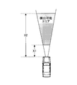
- FIG. 2 shows the figure showing the area which can detect a target object with the front sensor with which the driving assistance apparatus 10 of a present Example is provided.
- the driving support device 10 of the present embodiment is mounted on a vehicle and detects an object (another vehicle, a pedestrian, an obstacle such as a guardrail or a side wall) existing in front of the own vehicle, It is a device that provides driving assistance to the driver to avoid a collision between the vehicle and its object.
- the driving support device 10 includes a pre-crash control unit (hereinafter referred to as PCS-ECU) 12 mainly composed of a microcomputer.
- the PCS-ECU 12 performs various processes for providing driving assistance to the driver in order to avoid a collision between the host vehicle and the object.
- a vehicle speed sensor 14, a longitudinal acceleration sensor 16, a front sensor 18, an accelerator pedal sensor 20, and a brake pedal sensor 22 are electrically connected to the PCS-ECU 12, respectively.
- the vehicle speed sensor 14 is a sensor that outputs a signal corresponding to the vehicle speed of the host vehicle.
- the longitudinal acceleration sensor 16 is a sensor that outputs a signal corresponding to the longitudinal acceleration of the host vehicle.
- the output signal of the vehicle speed sensor 14 and the output signal of the longitudinal acceleration sensor 16 are supplied to the PCS-ECU 12, respectively.
- the PCS-ECU 12 detects the vehicle speed of the host vehicle based on the output signal supplied from the vehicle speed sensor 14 and detects the longitudinal acceleration of the host vehicle based on the output signal supplied from the longitudinal acceleration sensor 16.
- the front sensor 18 is disposed on a front bumper or front grill of the host vehicle, a rearview mirror stay in the vehicle interior, and the like, and images a radar device that transmits radio waves and lasers toward the front of the host vehicle or the front of the host vehicle. It consists of a camera.
- the radar device may be any device that emits millimeter waves or lasers, and the camera may be a stereo camera.
- the front sensor 18 transmits a millimeter wave or a laser from a radar device toward a predetermined detection area in front of the host vehicle, receives a millimeter wave or a laser reflected from an object existing in the predetermined detection area, and receives the host vehicle.
- a sensor that outputs a signal according to the relative distance, relative speed, and relative acceleration between the object and the object, or an object that exists in a predetermined detection area in front of the host vehicle by performing image processing on the captured image captured by the camera This is a sensor that extracts an object and outputs a signal corresponding to the relative distance, relative speed, and relative acceleration between the host vehicle and the object.
- the predetermined detection area in front of the host vehicle in which the front sensor 18 can detect the object is a second predetermined distance (for example, 200) from a position that is a first predetermined distance (for example, 1 meter) X1 from the front end of the host vehicle. M) The range up to a position separated by X2.
- the output signal of the front sensor 18 is supplied to the PCS-ECU 12.
- the PCS-ECU 12 detects the relative distance, relative speed, and relative acceleration between the host vehicle and the object based on the output signal supplied from the front sensor 18. Then, the PCS-ECU 12 calculates the possibility that the host vehicle will collide with the object based on the detected sensor information.
- the accelerator pedal sensor 20 is a sensor that outputs a signal according to whether or not the driver operates an accelerator pedal that is operated when the driver of the host vehicle accelerates the host vehicle.
- the brake pedal sensor 22 is a sensor that outputs a signal corresponding to whether or not the driver operates a brake pedal that is operated when the driver of the host vehicle brakes the host vehicle.
- the output signal of the accelerator pedal sensor 20 and the output signal of the brake pedal sensor 22 are supplied to the PCS-ECU 12, respectively.
- the PCS-ECU 12 determines whether or not the driver of the host vehicle operates the accelerator pedal based on the output signal supplied from the accelerator pedal sensor 20, and based on the output signal supplied from the brake pedal sensor 22. It is determined whether or not the driver of the host vehicle operates the brake pedal.
- the PCS-ECU 12 also includes a meter control unit (hereinafter referred to as a meter ECU) 24, a buzzer control unit (hereinafter referred to as a buzzer ECU) 26, and a brake control unit (hereinafter referred to as a buzzer ECU) each composed mainly of a microcomputer. , Referred to as a brake ECU) 28 is electrically connected.
- the PCS-ECU 12 reads the meter ECU 24, the buzzer ECU 26, and the brake when the possibility of collision between the host vehicle and the object calculated based on the detection results using the sensors 14 to 18 becomes higher than a predetermined level. A drive instruction is given to the ECU 28.
- the meter ECU 24 is electrically connected with a meter (for example, a combination meter) in the passenger compartment that is visible to the driver of the host vehicle as an alarm device.
- the meter ECU 24 can perform display control in the meter in accordance with instructions from the PCS-ECU 12.
- the buzzer ECU 26 is electrically connected to a buzzer in the passenger compartment that can be heard by the driver of the host vehicle as an alarm.
- the buzzer ECU 26 can perform a buzzer sounding process in accordance with an instruction from the PCS-ECU 12.
- a brake actuator that brakes the host vehicle is electrically connected to the brake ECU 28.
- the brake ECU 28 can brake the host vehicle by driving the brake actuator in accordance with an instruction from the PCS-ECU 12.
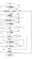
- FIG. 3 shows a flowchart of an example of a control routine executed by the PCS-ECU 12 in the driving support device 10 of the present embodiment.
- each part of the driving support device 10 is energized.
- the PCS-ECU 12 detects a target existing in a predetermined detection area in front of the host vehicle, and executes a process of providing driving support to the driver of the host vehicle. Specifically, first, based on output signals supplied from the vehicle speed sensor 14, the longitudinal acceleration sensor 16, and the front sensor 18, the vehicle speed and longitudinal acceleration of the host vehicle, and the relative distance and relative speed between the host vehicle and the object. And sensor information of relative acceleration is detected (step 100).
- the PCS-ECU 12 calculates the possibility that the host vehicle will collide with an object existing in a predetermined detection area in front of the host vehicle based on the sensor information detected in step 100. Then, it is determined whether or not the calculated collision possibility is greater than or equal to a predetermined value (step 102).
- the predetermined value is a reference value that is determined to be necessary to brake the host vehicle in order to avoid a collision between the host vehicle and an object, and is predetermined. As a result, for example, when the object does not exist in the predetermined detection area in front of the own vehicle, or when the object exists in the predetermined detection area, but the speed of the own vehicle is equal to or lower than the speed of the object. If it is determined that the possibility of collision between the host vehicle and the target object is less than the predetermined value, the current process is terminated without any further process.
- the PCS-ECU 12 determines that the possibility of collision between the host vehicle and the object is greater than or equal to a predetermined value, the PCS-ECU 12 determines that the host vehicle needs to be braked to avoid the collision.
- An automatic brake control for automatically braking the host vehicle as a collision avoidance control for performing an automatic driving operation for avoiding a collision between the host vehicle and an object while executing a process for starting an alarm for the driver of the vehicle (step 104).
- the process which starts is performed (step 106). Specifically, a drive instruction is given to the meter ECU 24, the buzzer ECU 26, and the brake ECU 28.
- a predetermined display is provided in the meter by a command from the meter ECU 24, thereby warning the driver to visually urge the brake operation, and a buzzer sounding by a command from the buzzer ECU 26.
- a warning for urging the driver to hear the brake operation is executed, and the vehicle is automatically braked by driving the brake actuator according to a command from the brake ECU 28.
- the PCS-ECU 12 is supplied again from the vehicle speed sensor 14, the longitudinal acceleration sensor 16, and the front sensor 18. Based on the output signal, sensor information of the vehicle speed and longitudinal acceleration of the host vehicle and the relative distance, relative speed, and relative acceleration between the host vehicle and the object are detected (step 108).
- the PCS-ECU 12 determines whether or not the collision between the host vehicle and the object has been avoided based on the sensor information detected in step 108 (step 110).
- the determination of collision avoidance is made, for example, based on whether or not the own vehicle has stopped based on the own vehicle speed by the vehicle speed sensor 14, and based on the relative speed by the front sensor 18, the vehicle speed of the own vehicle becomes equal to or lower than the speed of the object.
- Whether or not the detected object has moved out of the predetermined detection area for example, whether or not the host vehicle has avoided a collision with the target object by a steering operation by the driver of the host vehicle. Based on.
- step 106 the processing after step 106 is executed.
- the PCS-ECU 12 determines that there is no difference between the host vehicle and the target object such that the host vehicle is stopped, the vehicle speed of the host vehicle is equal to or lower than the target object speed, or the target object is not present in the predetermined detection area. If it is determined that the collision has been avoided, the automatic braking of the host vehicle by the brake actuator is released (step 112). Specifically, a drive stop instruction is given to the brake ECU 28. When such a drive stop instruction is issued, the brake actuator is stopped in response to a stop command from the brake ECU 28, thereby releasing the automatic braking of the host vehicle. When the automatic braking of the vehicle is released, the vehicle can subsequently travel due to inertia or a creep phenomenon, and can travel according to the driving operation of the driver.
- the PCS-ECU 12 determines whether or not the own vehicle is stopped when the automatic braking of the own vehicle is released (step 114). As a result, when it is determined that the host vehicle is stopped, it is next determined whether or not the driver of the host vehicle has performed the accelerator operation or not based on the output signal from the accelerator pedal sensor 20. At the same time, based on the output signal from the brake pedal sensor 22, it is determined whether or not the driver of the host vehicle has or has performed a brake operation (step 116). As a result, when it is determined that the driver has not performed the accelerator operation or the brake operation after the automatic braking of the host vehicle is released (when negative determination is made at step 118), the processing after step 116 is executed again.
- the PCS-ECU 12 indicates that the driver has performed the accelerator operation or the brake operation after the automatic braking of the host vehicle has been released, or that the driver has performed the accelerator operation or the brake operation when the automatic braking is released. If it is determined (when the determination in step 118 is affirmative), it is determined that the driving of the host vehicle is controlled by the driver's intention, and a process for terminating the warning for the driver is executed (step 120). Specifically, a drive stop instruction is issued to the meter ECU 24 and the buzzer ECU 26.
- the front sensor 18 is used to detect an object existing in a predetermined detection area in front of the host vehicle where the front sensor 18 can detect the object,
- a warning for the driver of the host vehicle and a buzzer may be performed, and automatic braking of the host vehicle by a brake actuator may be performed. it can.
- the driving assistance device 10 of the present embodiment when it is determined that the collision has been avoided after the driving assistance by the warning or automatic braking is started in order to avoid the collision between the own vehicle and the object,
- the subsequent automatic braking release timing and alarm end timing can be made different from each other. Specifically, when it is determined that the collision between the host vehicle and the object has been avoided, the automatic braking of the own vehicle is immediately released, and after the collision avoidance (that is, after the automatic braking is released), The alarm can be ended when the driver performs an accelerator operation or a brake operation.
- the automatic braking of the host vehicle is promptly released, and thereafter (that is, after the automatic braking is released), the driver of the host vehicle
- the alarm can be terminated at the timing when the accelerator operation or the brake operation is performed while continuing the alarm until the timing when the accelerator operation or the brake operation is performed.
- the warning for the driver of the host vehicle can be continued until the timing at which the accelerator operation or the brake operation is performed.
- the driver listens to the warning and performs the brake operation after the automatic braking of the host vehicle is released, for example, as compared with the configuration in which the automatic braking and the warning are simultaneously released.
- This facilitates the braking of the host vehicle, so that the host vehicle is creeping and the front sensor 18 cannot detect ahead of the host vehicle (for example, a first predetermined distance X1 from the front end of the host vehicle). It is possible to prevent contact with an object located below.
- the warning can be continued even after the automatic braking of the host vehicle is canceled, so that the driving safety when the driver drives the host vehicle on the road can be improved.
- the timing for releasing the automatic braking and the timing for ending the alarm after the collision between the host vehicle and the object is avoided are different from each other because the vehicle stops when the automatic braking is released. Only if you are. That is, if the host vehicle is traveling at the time when the automatic braking is released, the alarm by the meter display or buzzer sounding for the driver of the host vehicle is immediately terminated.
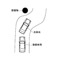
- the host vehicle Even if the automatic braking of the host vehicle is canceled when the collision between the host vehicle and the object is avoided, if the host vehicle continues to travel at the time of the cancellation, it is best to brake the host vehicle. It is not limited to vehicle operation, and it may be more appropriate for the vehicle to travel safely if the host vehicle is steered. For example, as shown in FIG. 4, when an obstacle is present in front of the host vehicle and a following vehicle is following the host vehicle, the host vehicle can avoid collision with the obstacle when the host vehicle can avoid the collision. If the vehicle is suddenly stopped by braking, there is a high possibility that the host vehicle will be collided from the following vehicle. For this reason, it is not appropriate to continuously issue a warning for prompting the driver to perform a brake operation after the collision between the host vehicle and the object is avoided.
- the driving of the host vehicle is performed. Regardless of whether the driver's accelerator operation or brake operation is performed, the alarm by the meter display or buzzer sounding for the driver of the own vehicle is immediately terminated. For this reason, if the host vehicle is running when the automatic braking of the host vehicle is released, the driver will not be encouraged to perform a brake operation by an alarm. It is possible to prevent misjudgment, that is, to cause the driver to operate the brake, and to suppress unnecessary warnings. Therefore, according to the present embodiment, the driving safety when the driver drives the vehicle on the road by appropriately and finely controlling the alarm appropriately according to the vehicle situation at the time of releasing the automatic braking. Can be secured.
- the PCS-ECU 12 detects an object existing in a predetermined detection area in front of the host vehicle.
- the “object detection means” described in the claims includes a meter and a buzzer.
- the accelerator operation or the brake operation by the driver is in the "predetermined driving operation” described in the claims, and the PCS-ECU 12 performs the process of step 104 in the routine shown in FIG.
- the PCS-ECU 12 executes the process of step 106 in “Collision avoidance control means” described in the claims.
- the “collision avoidance control” described in the claims is that the PCS-ECU 12 executes the processing of step 112 in “automatic brake starting means”.
- the PCS-ECU 12 executes the process of step 114 for the “stage” and the “automatic brake release means”.
- the PCS-ECU 12 executes the process of step 118 for the “run / stop determination means” recited in the claims.
- the PCS-ECU 12 executes the processing of step 120 in the “alarm control means” and “alarm end means” described in the claims. , Respectively.
- the collision avoidance margin until the host vehicle and the object collide based on the sensor information based on the sensor information of the relative distance, the relative speed, and the relative acceleration between the host vehicle and the object. Or calculating the probability that the subject vehicle and the target object are located on the same lane, and then integrating the calculated parameters to determine whether or not the above-described collision probability is higher than a predetermined value. Good.
- both alarm display by meter display and alarm sound by buzzer sound are performed as alarms to be performed when the possibility that the own vehicle collides with an object becomes higher than a predetermined value. Only one of the alarms may be performed.
- the host vehicle in order to determine that the collision between the host vehicle and the object has been avoided, the host vehicle has stopped, the vehicle speed of the host vehicle has become equal to or less than the target speed, or Although the condition is that the detected object has moved out of the predetermined detection area, only one of these three conditions may be set as the condition.
- the driver of the own vehicle performs an accelerator operation or a brake operation after the collision between the own vehicle and the object is avoided, that is, after the automatic braking is released, to end the alarm.
- it may be a condition that the driver of the own vehicle performs a brake operation, or may be a condition that the driver of the own vehicle performs an accelerator operation.
- it may be a condition that the driver of the own vehicle performs a steering operation for steering the own vehicle.
- the condition for starting the alarm and the condition for starting the automatic braking may be made different from each other. Specifically, conditions may be set so that automatic braking is started after an alarm is started.
- the present invention when it is determined that the possibility of collision between the host vehicle and the object is greater than or equal to a predetermined value, it is determined that the host vehicle needs to be braked to avoid the collision.
- the automatic brake control for automatically braking the host vehicle is performed as the collision avoidance control for performing the automatic driving operation for avoiding the collision with the object, the present invention is not limited to this. If it is determined that the possibility of collision with the target is greater than or equal to a predetermined value, it is determined that the collision between the host vehicle and the target can be avoided by steering the host vehicle. It is good also as applying to what performs steering control.
- Driving support device 12 PCS-ECU 14
- Vehicle speed sensor 16 Longitudinal acceleration sensor 18
- Front sensor 20 Accelerator pedal sensor 22
- Brake pedal sensor 24 Meter ECU 26
- Buzzer ECU 28 Brake ECU
Landscapes
- Engineering & Computer Science (AREA)
- Transportation (AREA)
- Mechanical Engineering (AREA)
- Automation & Control Theory (AREA)
- Physics & Mathematics (AREA)
- General Physics & Mathematics (AREA)
- Human Computer Interaction (AREA)
- Chemical & Material Sciences (AREA)
- Combustion & Propulsion (AREA)
- Traffic Control Systems (AREA)
- Regulating Braking Force (AREA)
Abstract
Description
12 PCS-ECU
14 車速センサ
16 前後加速度センサ
18 前方センサ
20 アクセルペダルセンサ
22 ブレーキペダルセンサ
24 メータECU
26 ブザーECU
28 ブレーキECU
Claims (11)
- 自車両前方の所定検出エリア内に存在する対象物を検出する対象物検出手段と、
前記対象物検出手段により検出された前記対象物に自車両が衝突する可能性が所定以上に高くなった場合に、自車両の運転者に向けて警報手段による警報を開始する警報制御手段と、
前記警報制御手段により前記警報が開始された以後に、前記対象物との衝突を回避するための自動運転操作を行う衝突回避制御を開始する衝突回避制御手段と、を備え、
前記警報制御手段は、前記衝突回避制御手段による前記衝突回避制御が終了した後の所定タイミングまで、前記警報を継続することを特徴とする運転支援装置。 - 前記所定タイミングは、自車両の運転者が所定運転操作を行う時点であることを特徴とする請求項1記載の運転支援装置。
- 前記衝突回避制御手段による前記衝突回避制御が終了した以後、自車両の運転者が所定運転操作を行うか否かを判別するドライバ操作判別手段を備え、
前記警報制御手段は、
前記対象物検出手段により検出された前記対象物に自車両が衝突する可能性が所定以上に高くなった場合に、自車両の運転者に向けて前記警報を開始する警報開始手段と、
前記ドライバ操作判別手段により自車両の運転者が前記所定運転操作を行ったと判別された場合に、前記警報を終了する警報終了手段と、
を有することを特徴とする請求項1記載の運転支援装置。 - 前記衝突回避制御手段による前記衝突回避制御が終了した終了時点で自車両が走行しているか或いは停車しているかを判別する走行/停止判別手段を備え、
前記警報終了手段は、前記走行/停止判別手段により自車両が前記終了時点で停車していると判別されかつ前記ドライバ操作判別手段により自車両の運転者が前記所定運転操作を行ったと判別された場合に、前記警報を終了することを特徴とする請求項3記載の運転支援装置。 - 前記警報終了手段は、また、前記走行/停止判別手段により自車両が前記終了時点で走行していると判別された場合に、前記警報を終了することを特徴とする請求項4記載の運転支援装置。
- 前記対象物検出手段は、レーダ装置又はカメラを用いて前記所定検出エリアとして自車両から第1所定距離離れた位置から第2所定距離離れた位置までに存在する対象物を検出することを特徴とする請求項1乃至5の何れか一項記載の運転支援装置。
- 前記警報は、自車両の運転者に自車両に対するブレーキ操作を促す警報表示又は警報吹鳴であることを特徴とする請求項1乃至6の何れか一項記載の運転支援装置。
- 前記衝突回避制御手段は、前記衝突回避制御を開始した後、自車両が停車した場合、自車両の速度が前記対象物の速度以下になった場合、又は前記対象物が前記所定検出エリア外に出た場合に、該衝突回避制御を終了することを特徴とする請求項1乃至7の何れか一項記載の運転支援装置。
- 前記衝突回避制御は、前記対象物との衝突を回避すべく自車両を自動制動させる自動ブレーキ制御、又は、前記対象物との衝突を回避すべく自車両を自動操舵させる自動操舵制御であることを特徴とする請求項1乃至8の何れか一項記載の運転支援装置。
- 前記衝突回避制御手段は、自車両の速度及び加速度並びに自車両と前記対象物検出手段により検出された前記対象物との相対距離、相対速度、及び相対加速度に基づいて自車両と該対象物との衝突を回避させるための制動が必要であると判定された場合に、前記衝突回避制御として自車両の自動制動を開始する自動ブレーキ開始手段を有することを特徴とする請求項1乃至8の何れか一項記載の運転支援装置。
- 前記衝突回避制御手段は、前記自動ブレーキ開始手段により前記自動制動が開始された後、自車両と前記対象物との衝突が回避された場合に、該自動制動を解除する自動ブレーキ解除手段を有することを特徴とする請求項10記載の運転支援装置。
Priority Applications (6)
| Application Number | Priority Date | Filing Date | Title |
|---|---|---|---|
| US14/008,804 US9478135B2 (en) | 2011-04-26 | 2011-04-26 | Drive support apparatus |
| DE112011105189.1T DE112011105189B4 (de) | 2011-04-26 | 2011-04-26 | Fahrunterstützungsvorrichtung |
| CN201180069881.7A CN103477378B (zh) | 2011-04-26 | 2011-04-26 | 驾驶辅助装置 |
| PCT/JP2011/060188 WO2012147166A1 (ja) | 2011-04-26 | 2011-04-26 | 運転支援装置 |
| JP2013511825A JPWO2012147166A1 (ja) | 2011-04-26 | 2011-04-26 | 運転支援装置 |
| US15/195,047 US9965955B2 (en) | 2011-04-26 | 2016-06-28 | Drive support apparatus |
Applications Claiming Priority (1)
| Application Number | Priority Date | Filing Date | Title |
|---|---|---|---|
| PCT/JP2011/060188 WO2012147166A1 (ja) | 2011-04-26 | 2011-04-26 | 運転支援装置 |
Related Child Applications (2)
| Application Number | Title | Priority Date | Filing Date |
|---|---|---|---|
| US14/008,804 A-371-Of-International US9478135B2 (en) | 2011-04-26 | 2011-04-26 | Drive support apparatus |
| US15/195,047 Division US9965955B2 (en) | 2011-04-26 | 2016-06-28 | Drive support apparatus |
Publications (1)
| Publication Number | Publication Date |
|---|---|
| WO2012147166A1 true WO2012147166A1 (ja) | 2012-11-01 |
Family
ID=47071708
Family Applications (1)
| Application Number | Title | Priority Date | Filing Date |
|---|---|---|---|
| PCT/JP2011/060188 Ceased WO2012147166A1 (ja) | 2011-04-26 | 2011-04-26 | 運転支援装置 |
Country Status (5)
| Country | Link |
|---|---|
| US (2) | US9478135B2 (ja) |
| JP (1) | JPWO2012147166A1 (ja) |
| CN (1) | CN103477378B (ja) |
| DE (1) | DE112011105189B4 (ja) |
| WO (1) | WO2012147166A1 (ja) |
Cited By (4)
| Publication number | Priority date | Publication date | Assignee | Title |
|---|---|---|---|---|
| JP2016162416A (ja) * | 2015-03-05 | 2016-09-05 | 株式会社デンソー | 運転支援装置、及び、運転支援方法 |
| KR101814784B1 (ko) * | 2013-07-30 | 2018-01-04 | 도요타 지도샤(주) | 차량 제어 방법 및 차량 제어 시스템 |
| JP2020038697A (ja) * | 2014-09-30 | 2020-03-12 | エイディシーテクノロジー株式会社 | 自動運転制御装置及び車両 |
| WO2022118788A1 (ja) * | 2020-12-01 | 2022-06-09 | 日野自動車株式会社 | 車両制御装置 |
Families Citing this family (40)
| Publication number | Priority date | Publication date | Assignee | Title |
|---|---|---|---|---|
| US9182761B2 (en) * | 2011-08-25 | 2015-11-10 | Nissan Motor Co., Ltd. | Autonomous driving control system for vehicle |
| US9656673B2 (en) * | 2013-12-04 | 2017-05-23 | Mobileye Vision Technologies Ltd. | Systems and methods for navigating a vehicle to a default lane |
| GB2523353B (en) * | 2014-02-21 | 2017-03-01 | Jaguar Land Rover Ltd | System for use in a vehicle |
| CA2893194C (en) * | 2014-07-30 | 2018-06-19 | Shigeru OHSUGI | Transporter vehicle and transporter vehicle control method |
| JP6561320B2 (ja) * | 2014-09-12 | 2019-08-21 | パナソニックIpマネジメント株式会社 | 衝突防止装置 |
| CN105988422B (zh) * | 2015-01-27 | 2019-05-21 | 上海海马汽车研发有限公司 | 一种车辆的远程驾驶控制系统及方法 |
| US9995386B2 (en) * | 2015-02-12 | 2018-06-12 | Honda Motor Co., Ltd. | Transmission control device for automatic transmission |
| DE102015208366B4 (de) * | 2015-05-06 | 2020-10-01 | Volkswagen Aktiengesellschaft | Automatische Notbremsung eines Kraftfahrzeugs |
| DE102015211133A1 (de) * | 2015-06-17 | 2016-12-22 | Robert Bosch Gmbh | Steuern eines Kraftfahrzeugs |
| KR101717080B1 (ko) * | 2015-06-17 | 2017-03-16 | 경창산업주식회사 | 승객을 보호하기 위한 차량 제어 시스템 및 이를 이용한 차량 제어 방법 |
| CN105346388B (zh) * | 2015-11-27 | 2019-03-05 | 江苏大学 | 一种用于汽车上坡时的辅助系统及其控制方法 |
| JP6530705B2 (ja) * | 2015-12-25 | 2019-06-12 | 株式会社デンソー | 運転支援装置及び運転支援方法 |
| JP6318189B2 (ja) * | 2016-04-20 | 2018-04-25 | 本田技研工業株式会社 | 燃料配管の保護構造 |
| KR101846734B1 (ko) * | 2016-11-09 | 2018-05-18 | 현대자동차주식회사 | 운전 상태 판단 장치 및 방법 |
| CN106781697B (zh) * | 2017-01-07 | 2019-08-23 | 山东科技大学 | 车载式不良天气实时感知及防碰撞预警方法 |
| DE102017200432B4 (de) | 2017-01-12 | 2022-08-18 | Audi Ag | Verfahren zum Betreiben eines Sicherheitssystems für ein Kraftfahrzeug und Sicherheitssystem |
| JP6834657B2 (ja) * | 2017-03-23 | 2021-02-24 | いすゞ自動車株式会社 | 車線逸脱警報装置の制御装置、車両および車線逸脱警報制御方法 |
| JP6922617B2 (ja) | 2017-09-28 | 2021-08-18 | トヨタ自動車株式会社 | 車両制御装置 |
| KR101982263B1 (ko) * | 2018-01-10 | 2019-05-27 | 주식회사 만도 | 차량 제어 장치 및 차량 제어 방법 |
| CN108407784B (zh) * | 2018-01-23 | 2021-12-07 | 内蒙古青杉汽车有限公司 | 一种基于模糊控制理论的防撞控制方法和装置 |
| JP6973194B2 (ja) * | 2018-03-08 | 2021-11-24 | トヨタ自動車株式会社 | 運転支援システム |
| CN108791284B (zh) * | 2018-05-16 | 2019-12-03 | 名商科技有限公司 | 一种电动汽车的驾驶辅助系统 |
| JP6973290B2 (ja) * | 2018-05-21 | 2021-11-24 | 株式会社デンソー | 走行支援装置 |
| CN108819928B (zh) * | 2018-05-25 | 2019-10-18 | 北京车和家信息技术有限公司 | 控制车辆运行的方法及装置 |
| KR101986824B1 (ko) * | 2018-06-28 | 2019-06-10 | 주식회사 만도 | 충돌 방지 장치 및 방법과, 운전 지원 장치 |
| JP7172626B2 (ja) * | 2019-01-16 | 2022-11-16 | トヨタ自動車株式会社 | 運転支援装置 |
| CN109724614B (zh) * | 2019-02-22 | 2021-06-04 | 百度在线网络技术(北京)有限公司 | 自动驾驶车辆的速度规划方法、装置和存储介质 |
| JP7226160B2 (ja) * | 2019-07-16 | 2023-02-21 | トヨタ自動車株式会社 | 車両走行制御装置 |
| JP7200871B2 (ja) | 2019-07-25 | 2023-01-10 | トヨタ自動車株式会社 | 衝突回避支援装置 |
| JP7343837B2 (ja) | 2019-10-03 | 2023-09-13 | トヨタ自動車株式会社 | 運転支援装置 |
| JP7255460B2 (ja) | 2019-11-15 | 2023-04-11 | トヨタ自動車株式会社 | 車両制御システム |
| JP7272241B2 (ja) | 2019-11-18 | 2023-05-12 | トヨタ自動車株式会社 | 車両走行制御装置及び車両制御システム |
| JP7147733B2 (ja) | 2019-11-22 | 2022-10-05 | トヨタ自動車株式会社 | 衝突回避支援装置 |
| JP7185188B2 (ja) | 2019-12-05 | 2022-12-07 | トヨタ自動車株式会社 | 衝突回避支援装置 |
| JP7272255B2 (ja) | 2019-12-16 | 2023-05-12 | トヨタ自動車株式会社 | 運転支援装置 |
| JP7290120B2 (ja) | 2020-02-03 | 2023-06-13 | トヨタ自動車株式会社 | 衝突回避支援装置 |
| US11679761B2 (en) * | 2020-04-03 | 2023-06-20 | Baidu Usa Llc | Forward collision warning alert system for autonomous driving vehicle safety operator |
| KR20220094298A (ko) * | 2020-12-28 | 2022-07-06 | 주식회사 에이치엘클레무브 | 차량 및 차량의 운전 보조 제어 방법 |
| EP4112411B1 (en) * | 2021-07-01 | 2024-03-27 | Zenseact AB | Estimation of accident intensity for vehicles |
| DE102021208998B4 (de) | 2021-08-17 | 2023-11-30 | Zf Friedrichshafen Ag | Verfahren zum Betreiben eines Fahrzeugs mit einem Fahrerassistenzsystem |
Citations (5)
| Publication number | Priority date | Publication date | Assignee | Title |
|---|---|---|---|---|
| JPH0687119U (ja) * | 1993-05-31 | 1994-12-20 | ダイハツ工業株式会社 | 車両の制動装置 |
| JPH1067301A (ja) * | 1996-08-29 | 1998-03-10 | Nissan Motor Co Ltd | 車両の接近警報装置 |
| JPH1148884A (ja) * | 1997-07-31 | 1999-02-23 | Nissan Motor Co Ltd | 車間距離警報装置 |
| JP2005047383A (ja) * | 2003-07-29 | 2005-02-24 | Daihatsu Motor Co Ltd | 運転支援装置 |
| JP2009120116A (ja) * | 2007-11-16 | 2009-06-04 | Hitachi Ltd | 車両衝突回避支援装置 |
Family Cites Families (28)
| Publication number | Priority date | Publication date | Assignee | Title |
|---|---|---|---|---|
| JP3155367B2 (ja) | 1992-09-04 | 2001-04-09 | 株式会社神戸製鋼所 | 混練機のロータ軸封装置 |
| JPH08150910A (ja) | 1994-11-30 | 1996-06-11 | Fuji Heavy Ind Ltd | 自動ブレーキ装置の制御装置 |
| DE19843564A1 (de) * | 1998-09-23 | 2000-03-30 | Bosch Gmbh Robert | Warneinrichtung für ein Kraftfahrzeug |
| JP3714116B2 (ja) * | 1999-08-09 | 2005-11-09 | トヨタ自動車株式会社 | 操縦安定性制御装置 |
| JP3966673B2 (ja) * | 1999-10-26 | 2007-08-29 | 本田技研工業株式会社 | 物体検知装置および車両の走行安全装置 |
| DE29920499U1 (de) | 1999-11-23 | 2000-02-17 | Schwarz Verbindungs-Systeme GmbH, 75382 Althengstett | Schwingungsdämpfende Verbindungsanordnung zum lösbaren Verbinden zweier Bauteile mit einem auf einem hülsengeführten Bolzen verschiebbaren Entriegelungsteil |
| JP2001171497A (ja) | 1999-12-17 | 2001-06-26 | Nissan Motor Co Ltd | 車両用衝突防止装置 |
| EP1349131B1 (en) * | 2000-11-24 | 2006-01-18 | Aisin Seiki Kabushiki Kaisha | Vehicle collision preventing apparatus |
| JP4803336B2 (ja) | 2001-07-19 | 2011-10-26 | 三菱自動車工業株式会社 | 障害物情報呈示装置 |
| EP1539523B1 (de) * | 2002-09-20 | 2006-05-03 | DaimlerChrysler AG | Verfahren und vorrichtung zur auslösung eines selbsttätigen notbremsvorgangs eines fahrzeugs |
| JP3951970B2 (ja) | 2003-06-24 | 2007-08-01 | トヨタ自動車株式会社 | 車両用走行制御装置 |
| CN1579842A (zh) * | 2003-08-14 | 2005-02-16 | 高凤岗 | 汽车追尾预警装置 |
| JP4756895B2 (ja) | 2005-04-07 | 2011-08-24 | アイシン・エィ・ダブリュ株式会社 | 走行支援装置 |
| JP4737519B2 (ja) | 2005-06-28 | 2011-08-03 | アイシン・エィ・ダブリュ株式会社 | 車両制御補助装置及び車両制御補助方法 |
| JP4684954B2 (ja) | 2005-08-31 | 2011-05-18 | 本田技研工業株式会社 | 車両の走行安全装置 |
| JP2007249539A (ja) * | 2006-03-15 | 2007-09-27 | Autech Japan Inc | 車両用警報装置および前方障害物回避特性抽出装置 |
| DE102006047131A1 (de) * | 2006-10-05 | 2008-04-10 | Robert Bosch Gmbh | Verfahren zum automatischen Steuern eines Fahrzeugs |
| US7719410B2 (en) | 2007-01-08 | 2010-05-18 | Gm Global Technology Operations, Inc. | Threat assessment state processing for collision warning, mitigation and/or avoidance in ground-based vehicles |
| JP2008189139A (ja) * | 2007-02-05 | 2008-08-21 | Mazda Motor Corp | 車両用運転支援装置 |
| JP4386082B2 (ja) * | 2007-02-20 | 2009-12-16 | トヨタ自動車株式会社 | 車両走行支援装置 |
| JP4941059B2 (ja) | 2007-04-02 | 2012-05-30 | 株式会社豊田中央研究所 | 運転支援装置 |
| US7733266B2 (en) * | 2007-09-06 | 2010-06-08 | Honda Motor Co., Ltd. | Control target recognition system and vehicle object detection system |
| JP5345350B2 (ja) | 2008-07-30 | 2013-11-20 | 富士重工業株式会社 | 車両の運転支援装置 |
| DE102008038540A1 (de) | 2008-08-20 | 2010-02-25 | Wabco Gmbh | Verfahren zur Steuerung einer Brems- und/oder Motormomentansteuerung und Vorrichtung zur Durchführung des Verfahrens |
| JP5282590B2 (ja) * | 2009-01-30 | 2013-09-04 | 日産自動車株式会社 | 車両用運転支援装置および車両用運転支援方法 |
| CN103109312A (zh) * | 2010-07-17 | 2013-05-15 | 法雷奥开关和传感器有限责任公司 | 一种用于警告机动车辆的驾驶员在靠近车辆的侧板的侧部区域中存在障碍物的方法以及具有驾驶员辅助系统的机动车辆 |
| JP2012144162A (ja) * | 2011-01-12 | 2012-08-02 | Toyota Motor Corp | 走行支援装置 |
| JP5793868B2 (ja) * | 2011-01-12 | 2015-10-14 | トヨタ自動車株式会社 | 走行支援装置 |
-
2011
- 2011-04-26 JP JP2013511825A patent/JPWO2012147166A1/ja active Pending
- 2011-04-26 DE DE112011105189.1T patent/DE112011105189B4/de active Active
- 2011-04-26 US US14/008,804 patent/US9478135B2/en active Active
- 2011-04-26 WO PCT/JP2011/060188 patent/WO2012147166A1/ja not_active Ceased
- 2011-04-26 CN CN201180069881.7A patent/CN103477378B/zh active Active
-
2016
- 2016-06-28 US US15/195,047 patent/US9965955B2/en active Active
Patent Citations (5)
| Publication number | Priority date | Publication date | Assignee | Title |
|---|---|---|---|---|
| JPH0687119U (ja) * | 1993-05-31 | 1994-12-20 | ダイハツ工業株式会社 | 車両の制動装置 |
| JPH1067301A (ja) * | 1996-08-29 | 1998-03-10 | Nissan Motor Co Ltd | 車両の接近警報装置 |
| JPH1148884A (ja) * | 1997-07-31 | 1999-02-23 | Nissan Motor Co Ltd | 車間距離警報装置 |
| JP2005047383A (ja) * | 2003-07-29 | 2005-02-24 | Daihatsu Motor Co Ltd | 運転支援装置 |
| JP2009120116A (ja) * | 2007-11-16 | 2009-06-04 | Hitachi Ltd | 車両衝突回避支援装置 |
Cited By (11)
| Publication number | Priority date | Publication date | Assignee | Title |
|---|---|---|---|---|
| KR101814784B1 (ko) * | 2013-07-30 | 2018-01-04 | 도요타 지도샤(주) | 차량 제어 방법 및 차량 제어 시스템 |
| KR20180004312A (ko) * | 2013-07-30 | 2018-01-10 | 도요타 지도샤(주) | 차량 제어 방법 및 차량 제어 시스템 |
| US10099688B2 (en) | 2013-07-30 | 2018-10-16 | Toyota Jidosha Kabushiki Kaisha | Vehicle control method and vehicle control system |
| KR101976973B1 (ko) * | 2013-07-30 | 2019-05-09 | 도요타 지도샤(주) | 차량 제어 방법 및 차량 제어 시스템 |
| US10843688B2 (en) | 2013-07-30 | 2020-11-24 | Toyota Jidosha Kabushiki Kaisha | Vehicle control method and vehicle control system |
| US10864909B2 (en) | 2013-07-30 | 2020-12-15 | Toyota Jidosha Kabushiki Kaisha | Vehicle control method and vehicle control system |
| JP2020038697A (ja) * | 2014-09-30 | 2020-03-12 | エイディシーテクノロジー株式会社 | 自動運転制御装置及び車両 |
| JP2021102436A (ja) * | 2014-09-30 | 2021-07-15 | Case特許株式会社 | 自動運転制御装置及び車両 |
| JP7082265B2 (ja) | 2014-09-30 | 2022-06-08 | Case特許株式会社 | 自動運転制御装置及び車両 |
| JP2016162416A (ja) * | 2015-03-05 | 2016-09-05 | 株式会社デンソー | 運転支援装置、及び、運転支援方法 |
| WO2022118788A1 (ja) * | 2020-12-01 | 2022-06-09 | 日野自動車株式会社 | 車両制御装置 |
Also Published As
| Publication number | Publication date |
|---|---|
| JPWO2012147166A1 (ja) | 2014-07-28 |
| US9965955B2 (en) | 2018-05-08 |
| CN103477378A (zh) | 2013-12-25 |
| CN103477378B (zh) | 2016-10-12 |
| US20160304090A1 (en) | 2016-10-20 |
| DE112011105189B4 (de) | 2024-12-12 |
| DE112011105189T5 (de) | 2014-01-23 |
| US9478135B2 (en) | 2016-10-25 |
| US20140222289A1 (en) | 2014-08-07 |
Similar Documents
| Publication | Publication Date | Title |
|---|---|---|
| WO2012147166A1 (ja) | 運転支援装置 | |
| JP5987906B2 (ja) | 運転支援装置 | |
| CN105835819B (zh) | 车辆制动控制装置 | |
| US10501122B2 (en) | Driving assistance device | |
| KR101665451B1 (ko) | 차량의 긴급제동 상황 판단 방법 및 장치 | |
| CN104487309B (zh) | 驾驶辅助装置 | |
| CN106114494B (zh) | 一种用于车辆的倒车辅助防碰撞系统及方法 | |
| JP6090396B2 (ja) | 運転支援装置 | |
| JP2021020497A (ja) | 衝突回避支援装置 | |
| JP2021109507A (ja) | 運転支援装置 | |
| CN107848535B (zh) | 起步控制装置以及起步控制方法 | |
| JP5566445B2 (ja) | 運転支援装置 | |
| JP7505509B2 (ja) | 車両運転支援装置 | |
| JP2008296886A (ja) | 車両用制動支援装置 | |
| JP2017045367A (ja) | 車両制御装置および車両制御方法 | |
| US12139121B2 (en) | Vehicle control device, vehicle control method, and computer-readable recording medium having stored thereon vehicle control program | |
| JP5896062B2 (ja) | 運転支援装置 | |
| JP5649641B2 (ja) | 運転支援装置 | |
| US20240278776A1 (en) | Method and apparatus for collision avoidance or impact force reduction | |
| JP6257349B2 (ja) | 運転支援装置 | |
| JP2007069728A (ja) | 走行制御装置 | |
| KR20220071559A (ko) | 긴급제동 제어 시스템 및 그 방법 | |
| JP7433734B2 (ja) | 運転支援装置 | |
| JP2009101808A (ja) | 車両用運転支援装置 | |
| JP2023035541A (ja) | 車線逸脱防止装置 |
Legal Events
| Date | Code | Title | Description |
|---|---|---|---|
| 121 | Ep: the epo has been informed by wipo that ep was designated in this application |
Ref document number: 11864352 Country of ref document: EP Kind code of ref document: A1 |
|
| ENP | Entry into the national phase |
Ref document number: 2013511825 Country of ref document: JP Kind code of ref document: A |
|
| WWE | Wipo information: entry into national phase |
Ref document number: 14008804 Country of ref document: US |
|
| WWE | Wipo information: entry into national phase |
Ref document number: 112011105189 Country of ref document: DE Ref document number: 1120111051891 Country of ref document: DE |
|
| 122 | Ep: pct application non-entry in european phase |
Ref document number: 11864352 Country of ref document: EP Kind code of ref document: A1 |