WO2012144282A1 - 電気部品装着機および電気回路製造方法 - Google Patents
電気部品装着機および電気回路製造方法 Download PDFInfo
- Publication number
- WO2012144282A1 WO2012144282A1 PCT/JP2012/056747 JP2012056747W WO2012144282A1 WO 2012144282 A1 WO2012144282 A1 WO 2012144282A1 JP 2012056747 W JP2012056747 W JP 2012056747W WO 2012144282 A1 WO2012144282 A1 WO 2012144282A1
- Authority
- WO
- WIPO (PCT)
- Prior art keywords
- mounting
- component
- electrical component
- imaging
- imaging device
- Prior art date
Links
Images


Classifications
-
- H—ELECTRICITY
- H05—ELECTRIC TECHNIQUES NOT OTHERWISE PROVIDED FOR
- H05K—PRINTED CIRCUITS; CASINGS OR CONSTRUCTIONAL DETAILS OF ELECTRIC APPARATUS; MANUFACTURE OF ASSEMBLAGES OF ELECTRICAL COMPONENTS
- H05K13/00—Apparatus or processes specially adapted for manufacturing or adjusting assemblages of electric components
- H05K13/08—Monitoring manufacture of assemblages
- H05K13/081—Integration of optical monitoring devices in assembly lines; Processes using optical monitoring devices specially adapted for controlling devices or machines in assembly lines
- H05K13/0812—Integration of optical monitoring devices in assembly lines; Processes using optical monitoring devices specially adapted for controlling devices or machines in assembly lines the monitoring devices being integrated in the mounting machine, e.g. for monitoring components, leads, component placement
Definitions
- the present invention relates to an electric component mounting machine for mounting an electric component on a circuit board, and an electric circuit manufacturing method for manufacturing an electric circuit by mounting the electric component on the circuit board.
- the electrical circuit is manufactured by mounting electrical components on a circuit board.
- component mounting when mounting this electrical component (hereinafter sometimes referred to as “component mounting”), for example, as described in the following patent document,
- the held electrical component is imaged from below by the component imaging device, and the substrate reference mark attached to the surface of the substrate fixed by the substrate fixing device is imaged by the substrate imaging device, and imaging data obtained by the imaging Then, the electrical component is mounted at an appropriate mounting position on the circuit board. In addition, after the component is mounted, the mounting position is also confirmed.
- the present invention is based on this finding, and an object of the present invention is to provide an electric component mounting machine and an electric circuit manufacturing method with high practicality.
- an electrical component mounting machine is disposed in a predetermined imaging device moving device, that is, a mounting head or a portion to which the mounting head is attached, and at least a board imaging device and a component imaging.
- An image pickup apparatus moving apparatus that supports one of the apparatus and that can move between a position below the holder where the one is positioned below the component holder and a retracted position retracted from the position. It is characterized by that.
- the electrical circuit manufacturing method of the present invention images an electrical component having a bump, grasps the relative positional deviation amount between the contour of the electrical component and the bump, and calculates the relative positional deviation amount. In addition, the mounting position of the electrical component after the mounting is confirmed.
- the electrical component mounting machine of the present invention in a state where the electrical component is located above the mounting part of the circuit board, at least one of imaging data from above the mounting part and imaging data from below the electrical part.
- the electronic component can be acquired based on the acquired imaging data without moving the mounting head by the head moving device by retracting one of the board imaging device and the component imaging device after acquiring the imaging data. Can be attached to the attachment site. As a result, it is possible to perform component mounting with high accuracy.
- the image pickup device moving device moves the substrate imaging device and the component between the lower position of the holder and the retracted position. It becomes possible to properly position one of the imaging device and the holder below. This contributes to increasing the accuracy of component mounting.
- an electrical component having a bump on the lower surface is added to the contour after mounting by adding the relative positional deviation amount between the contour grasped before mounting and the bump. It is possible to check the mounting position based on the accuracy.
- (2) is in claim 1
- (4) is in claim 2
- (7) is in claim 3
- (8) is in claim 4
- (9) is In claim 5
- the (10) term corresponds to claim 6
- the (11) term corresponds to claim 7
- the (21) term corresponds to claim 8.
- a board fixing device for fixing a circuit board
- a mounting head for mounting the electrical component held on the circuit board fixed to the board fixing device, having a component holder for holding the electrical component
- a head mounting body to which the mounting head is mounted
- a head moving device that moves the mounting head along the surface of the circuit board fixed to the substrate fixing device by moving the head mounting body
- a board imaging device for imaging the surface of the circuit board fixed to the board fixing device from above the circuit board
- a component imaging device for imaging an electrical component held by the component holder of the mounting head from below, and supporting at least one of the board imaging device and the component imaging device,
- An electrical component mounting machine comprising: an imaging device moving device that is movable between a holder lower position positioned below the component holder and a retracted position retracted from the position.
- the board imaging device and the component imaging device It is possible to configure one of the positions below the holder, that is, between the portion of the circuit board and the electrical component held by the component holder.
- mounting portion In the state where the electrical component is located above the portion of the circuit board where the electrical component is mounted (hereinafter referred to as “mounting portion”), Image data or image data from below the electrical component can be acquired, and after the acquisition of the imaging data, the mounting head is moved by the head moving device by retracting one of the substrate imaging device and the component imaging device The electrical component can be mounted on the mounting site based on the acquired imaging data. As a result, it is possible to perform component mounting with high accuracy. This is effective when mounting an electrical component that requires particularly high mounting accuracy, such as an electrical component having a plurality of bumps described later.
- the “imaging device moving device” described in this section may support both the board imaging device and the component imaging device, as will be described later.
- the electrical component mounting machine of this section can be configured such that the component imaging device is fixed to any part of the electrical component mounting machine, When only the component imaging device is supported, the substrate imaging device can be configured to be fixed to the mounting head or the head mounting body.
- the electrical component mounting machine of this section includes two or more board imaging devices or two or more component imaging devices, only one of them is supported by the imaging device moving device and moved to the lower position of the holder. Can be configured.
- the “imaging device moving device” refers to one of the board imaging device and the component imaging device (hereinafter sometimes referred to as “one imaging device” and the other as “the other imaging device”) in one direction.
- one imaging device and the other as “the other imaging device”
- the imaging device may be moved in an arbitrary direction within one plane. When it is moved only in one direction, it may be moved linearly or may be moved so as to rotate around any position.
- only one retraction position is set relative to the lower position of the holder with respect to one lower position of the holder, and one imaging device is placed below the holder.
- the mounting head may be configured to move between a position and a retracted position, and is configured to move between a plurality of retracted positions that can be set or arbitrary with respect to the holder lower position. It may be. Further, when the mounting head has a plurality of electric component holders, one of the images is taken between a plurality of holder lower positions set in correspondence with the plurality of electric component holders and a retracted position. It may be configured to move the device. Note that “positioning the imaging device below the component holder” strictly means that the light receiving unit of the imaging device is positioned below the component holder.
- the imaging device moving device is The electrical component mounting machine according to (1), which is disposed on the mounting head or the head mounting body.
- the mounting head is moved by the head moving device, so that the electrical component held by the component holder is positioned above the mounting site.
- the head moving device is, for example, an XY robot type moving device
- a ball screw mechanism that moves the mounting head in the X direction or the Y direction is generally employed. Even if the electrical component is positioned above the mounting site due to subtle bending of the screw rod constituting the ball screw mechanism or variation due to the position of the screw pitch, a certain amount of deviation occurs from the proper position. there is a possibility.
- the imaging device moving device is an XY robot type moving device different from the head moving device, even if one imaging device is positioned at the holder lower position, A certain amount of deviation may occur from an appropriate position.
- the imaging device moving device is an XY robot type moving device different from the head moving device, even if one imaging device is positioned at the holder lower position, A certain amount of deviation may occur from an appropriate position.
- the imaging device moving device when the component holder is moved above the mounting portion of the circuit board fixed by the substrate fixing device, one of the imaging devices supported by the imaging device moving device is a head together with the mounting head. If the image pickup device moving device is moved between the holder lower position and the retracted position by the image pickup device moving device in the moved state, the one image pickup device is positioned at an appropriate holder lower position. It becomes possible to make it.
- the imaging device moving device is attached to the head mounting body in consideration of the advantage that the imaging device can be shared by any mounting head. It is desirable to be disposed.
- the imaging device moving device is Item (1) or Item (2), which has a vertical displacement mechanism capable of displacing one of the board imaging device and the component imaging device in the vertical direction in a state where one of them is positioned below the holder. Electric component mounting machine.
- the electrical component mounting machine of this section is excellent in convenience because it can easily cope with a difference in height (level) of the mounting site, a difference in thickness of the electrical component, etc. in imaging by one imaging device. If it explains in detail using a specific example, when one imaging device supported by the imaging device moving device is positioned at a lower position of the holder, the electrical component held by the component holder and the board fixing device It will be located between the fixed circuit board. Accordingly, since the distance between the electric component and the circuit board is relatively small, one of the imaging devices is required to be compact. Under this requirement, one imaging device may be forced to be an imaging device whose focal length cannot be adjusted, that is, a fixed focus type imaging device.
- the “vertical displacement mechanism” may be configured to be displaced in the vertical direction only when one of the imaging devices is positioned at the holder lower position, and between the holder lower position and the retracted position. Any of these positions may be configured to be displaced in the vertical direction.
- the image pickup device moving device supports the other of the board image pickup device and the component image pickup device, and the other is a holder lower position where it is located below the component holder,
- the electrical component mounting machine according to any one of (1) to (3), wherein the electrical component mounting machine is configured to move between a retracted position retracted from a position.
- the imaging device moving device in this section may be a device that moves the board imaging device and the component imaging device integrally as will be described later, and a moving mechanism that moves the board imaging device.
- a moving mechanism for moving the component imaging device that is, two moving mechanisms may be provided to move them independently of each other.
- the electrical component mounting machine of this section can be interpreted as a mounting machine configured such that the imaging apparatus moving device moves both of the two imaging apparatuses by one moving mechanism.
- the two imaging devices themselves may be integrated.
- an imaging device that has a board imaging function and a component imaging function and is configured as one imaging device.
- the image pickup device and two image pickup devices each having an optical path for forming an image on the image pickup device may be fixed to each other.
- An element, two optical paths that form an image from each of the electrical component and the circuit board with respect to the imaging element, and a mechanism for switching the two optical paths may be used.
- the two imaging devices may be moved integrally to one holder lower position set in common to the two imaging devices.
- the two imaging devices may be moved integrally in each of the two positions below the two holders set corresponding to the imaging device.
- the board imaging device and the component imaging device are supported by the imaging device moving device so that when one of them is located at the lower position of the holder, the other is located at the lower position of the holder.
- the electrical component mounting machine described in (5) The electrical component mounting machine described in (5).
- the electrical component mounting machine of this section moves the image pickup apparatus moving device described above, that is, the two image pickup apparatuses integrally to one holding tool lower position set in common to them. It can be considered that it is a component mounting machine provided with such an imaging device moving device.
- the board imaging device and the component imaging device described in this section the two optical axes directed to each of the circuit board and the electrical component in the imaging are made to coincide with each other, that is, they face each other on one axis. It is desirable to be configured as follows.
- the electrical component mounting machine includes a control device that controls the electrical component mounting machine,
- the control unit is The imaging device moving device is controlled in a state in which the electrical component held by the component holder is positioned above a mounting portion where the electrical component is mounted on the circuit board fixed by the substrate fixing device. Then, each of the board imaging device and the component imaging device is positioned at the lower position of the holder, and the board imaging is performed in a state where each of the board imaging device and the component imaging apparatus is positioned at the lower position of the holder.
- a pre-mounting imaging control unit that controls the apparatus and the component imaging device to image the mounting part and the electrical component held by the component holder; Based on the imaging data of the mounting site imaged by the board imaging device and the imaging data of the electrical component imaged by the component imaging device, the amount of relative positional deviation between the mounting site and the electrical component is grasped.
- a deviation amount grasping unit A correction amount determination unit that determines a correction amount for a mounting position when the electrical component is mounted on the mounting site based on the relative positional shift amount between the mounting site and the electrical component grasped by the misalignment amount grasping unit.
- the electrical component mounting machine in this section is an electrical component mounting machine in which a limitation is imposed on the component mounting process to be executed.
- the electrical component held by the component holder is positioned above the mounting portion of the electrical component on the circuit board fixed by the substrate fixing device.
- the electrical component mounting machine of this section does not require mounting according to the above process on all of the plurality of electrical components mounted on one circuit board, for example, a plurality of electrical components.
- mounting position described in this specification including this section does not mean only the position in the direction along the surface of the circuit board, but also includes the rotational position (orientation).
- relative positional deviation amount does not mean only a positional deviation in the direction along the surface of the circuit board, but also includes a rotational positional deviation (azimuth deviation).
- the electrical component held by the component holder has one or more bumps on the lower surface, and one or more lands on which the one or more bumps are respectively placed on the mounting portion of the circuit board.
- the deviation amount grasping unit is configured to grasp a relative positional deviation amount between the one or more lands and the one or more bumps as a relative positional deviation amount between the mounting portion and the electrical component.
- electrical parts having bumps are required to have high mounting accuracy.
- an electrical component in which a plurality of bumps are arranged at a small pitch is highly likely to be short-circuited due to a displacement of the mounting position, and requires considerably high mounting accuracy.
- the electrical component mounting apparatus of this section performs mounting of an electrical component having a bump in consideration of the relative positional deviation between the bump and the land on which the bump is placed. Therefore, mounting with high accuracy can be performed.
- the control device After the electrical component held by the component holder is mounted on the mounting site, the imaging device moving device is controlled so that the board imaging device is positioned below the holder and the board imaging device is controlled. And a post-mounting imaging control unit that images the electrical component mounted on the mounting site; (7) or (8) having a mounting position confirmation unit that confirms the mounting position of the electrical component based on imaging data of the electrical component mounted on the mounting site imaged by the board imaging device.
- the relative positional deviation amount between the mounting part of the circuit board and the electrical component is grasped, and the correction is performed based on the relative positional deviation amount.
- the mounting position of the component is shifted due to the operation for mounting the electrical component on the substrate surface from above the part, that is, the component mounting operation. Specifically, when the component holder descends slightly but obliquely, the mounting position shift occurs when the tip surface of the component holder and the surface of the circuit board are slightly but not parallel. Further, there is a possibility that the mounting position is shifted due to the correction operation performed in the component mounting operation, that is, the correction operation.
- the mounting position is deviated.
- the electrical component mounting machine of this section after mounting the electrical component, the electrical component mounted on the circuit board is imaged by the substrate imaging device at the same position as before mounting without moving the mounting head by the head moving device.
- the mounting position of the electrical component can be confirmed with high accuracy. Therefore, according to the electrical component mounting machine of this section, high mounting accuracy can be ensured by confirming the mounting position performed as described above.
- the electrical component held by the component holder has one or more bumps on the lower surface, and one or more lands on which the one or more bumps are respectively placed on the mounting portion of the circuit board.
- the deviation amount grasping unit is configured to grasp a relative positional deviation amount between an outline of the electrical component and the one or more bumps based on imaging data of the electrical component imaged by the component imaging device.
- the mounting position confirmation unit is configured to confirm the mounting position of the electrical component mounted on the mounting site while taking into account the relative positional deviation between the grasped contour of the electrical component and one or more bumps.
- the electrical component having the bumps on the lower surface is mounted such that the bumps are placed on the lands formed on the mounting portion of the circuit board.
- the mounting position of the electrical component is appropriate.
- the bump is provided at an appropriate position of the electric component.
- the position of the bump in the electric component may vary for each lot of the electric component.
- the relative positional deviation amount between the contour of the electrical component and the bump contributes to confirming the mounting position with high accuracy.
- the relative positional deviation amount between the contour of the electrical component and the bump is grasped based on the imaging data by the component imaging device, and the board imaging is performed in consideration of the relative positional deviation amount. Since the mounting position is confirmed based on the imaging data by the apparatus, the mounting position can be confirmed with high accuracy.
- the correction amount determination unit According to the item (9) or the item (10), which is configured to determine the correction amount with reference to data on the mounting position confirmed by the mounting position confirmation unit for the electrical component mounted before the previous time. Electrical component mounting machine.
- a specific method for determining the correction amount based on the confirmation result is not particularly limited. For example, an average and a weighting are applied to each mounting position shift amount of a plurality of electrical components mounted before the previous time. Processing may be performed in accordance with a statistical method such as averaging, and a correction amount may be determined by adding a value obtained by the processing as a value representing a tendency of mounting position deviation.
- the control device It is configured to update data relating to the mounting position referred to by the correction amount determination unit when at least one of an event of changing a lot of electrical components, changing a lot of circuit boards, and replacing the component holder occurs.
- the tendency of electrical component mounting position shifts will change as mounting conditions change.
- the events listed in this section that is, when the “Electric component lot”, “Circuit board lot”, and “Component holder” change, the tendency may change to some extent. high.
- the electrical component mounting machine in this section takes this into consideration and changes the data to be referred to when those events occur.
- the specific mode of data update is not particularly limited. For example, when those events occur, the data that has been referred to so far is discarded, and thereafter, the data of the reference data is newly It is possible to adopt a mode in which accumulation is started, that is, a mode in which data is reset.
- a component mounting step of mounting the electrical component on a mounting portion of a circuit board on which one or more lands on which the one or more bumps are respectively mounted are formed;
- the electrical component mounted on the circuit board is imaged by an imaging device, and a component upper surface imaging data acquisition step of acquiring imaging data of the upper surface of the electrical component;
- the imaging data processing device determines the contour of the electrical component and one or more bumps detected in the deviation amount grasping step.
- the aspect of this section is an aspect relating to an electric circuit manufacturing method characterized by confirming the mounting position of the electrical component after the electrical component is mounted on the circuit board.
- an electrical component having a bump on the lower surface is mounted so that the bump is properly placed on a land provided in the mounting portion of the circuit board. Cannot be recognized. Therefore, the mounting position is confirmed based on the outline of the electrical component.
- the electrical circuit manufacturing method of this section the relative position deviation amount between the outline of the electrical component and the bump is grasped, and the mounting position is confirmed by taking the relative position deviation amount into consideration. It is possible to accurately check the mounting position of the electric component.
- the electrical circuit manufacturing method of this section does not require the mounting position confirmation process to be performed in the electrical component mounting machine that performs the component mounting process.
- a mounting result inspection machine for inspecting the mounting result may be installed separately from the electrical component mounting machine that performs the component mounting process, and the mounting position confirmation process may be performed by the inspection machine.
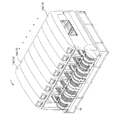
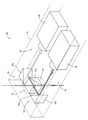
- FIG. 1 It is a perspective view which shows the electrical component mounting system comprised including the mounting module (a kind of work module) as an electrical component mounting machine of an Example. It is a perspective view which shows the mounting module which the electric component mounting system of FIG. 1 has. It is a perspective view which shows the mounting head with which the mounting module of FIG. 2 is equipped, and the head moving apparatus which moves the mounting head. It is a perspective view which shows the work head which can be attached to each work module of the electrical component mounting system of FIG. It is a perspective view which shows the imaging unit attached to the mounting module of FIG. It is a perspective view which shows the internal structure of the vertical-view camera which comprises the imaging unit of FIG. It is a figure showing the imaging unit of FIG. 5 in the viewpoint from the side.
- FIG. 7 is an image of a top surface of a mounting part based on imaging data obtained by imaging of a component camera constituting the vertical field of view camera in FIG. 6, assuming that the mounting position of the component is not shifted due to the component mounting operation
- FIG. 6
- FIG. 7 is an image of a top surface of a mounting part based on imaging data obtained by imaging with a component camera constituting the vertical field-of-view camera in FIG. 6, and the mounting position of the component is shifted from the mounting position due to a component mounting operation. It is a figure which shows an image in the case of being.
- FIG. 3 is a functional block diagram illustrating a control device that is mounted on the mounting module of FIG. 2 and controls the mounting module.
- FIG. 1 shows an electrical component mounting system including an electrical component mounting machine according to an embodiment.
- This system includes a base module 10 and eight work modules 12 a arranged side by side on the base module 10. , 12b (hereinafter may be collectively referred to as “work module 12”).
- a circuit board hereinafter simply referred to as “substrate” used for work is directed from the work module 12 on the upstream side (front side in the figure) toward the work module 12 on the downstream side (back side in the figure). The work is sequentially carried out by the work modules 12, and the work by the system is completed.
- the mounting modules 12a for mounting electrical components (hereinafter simply referred to as “components”) on the board, and are the most downstream.
- the one located at is an inspection module 12b for inspecting the result of component mounting by the mounting module 12a.
- Each of the seven mounting modules 12a functions as an electrical component mounting machine of the embodiment, and one inspection module 12b functions as a mounting result inspection machine.
- a solder printer that screen-prints cream solder on the surface of the board is arranged, and on the downstream side, a reflow furnace for heating the board on which the components are mounted is arranged.
- the electric circuit manufacturing line is configured by the above. Therefore, the electrical component mounting system shown in the figure performs a part of the work in the electrical circuit manufacturing.
- FIG. 2 shows the mounting module 12a with the exterior panel removed.
- the mounting module 12a includes a base 14, a beam 16 overlaid on the base 14, and a base 14
- a substrate conveyor device 18 disposed in the front, a plurality of component feeders 20 that are interchangeably attached to the base 14 on the front side of the module 12a, and each function as a component supply device, and a substrate conveyor device 18 and a plurality of components
- a base-fixed component camera 22 fixed to the base 14 between the feeder 20 and a component supplied from one of the plurality of component feeders 20 is held and the component is detached for mounting on the substrate S.
- the mounting head 24a (which is a kind of “working head 24”) and the beam 16 are arranged to move the mounting head 24a. It is configured to include a head moving unit 26 that.
- the substrate conveyor device 18 has two tracks (lanes) for transporting the substrate, and the substrate is loaded into each track from the upstream side and unloaded from each track to the downstream side.
- the substrate conveyor device 18 has a support table that can be moved up and down at the lower part of each track, and the substrate S carried to a predetermined position is supported by the raised support table and fixed at that position. That is, the substrate conveyor device 18 functions as a substrate fixing device that fixes the substrate S at a predetermined work position in the mounting operation. Since the board conveyor device 18 is disposed in each work module 12, the system can mount components in two lanes.
- the substrate transport direction which is the substrate transport direction by the substrate conveyor device 18 is the X direction shown in the figure (shown with arrows together with the Y direction and Z direction).
- the head moving device 26 is a so-called XY type moving device, and includes a Y-direction moving device 28 and an X-direction moving device 30 (the X direction, the Y direction, and the Z direction are respectively (Shown with arrows in the figure). More specifically, the Y-direction moving device 28 includes a pair of Y guides 32 fixed to the beam 16, a Y slide 34 guided by the pair of Y guides 32, and a Y slide movement that moves the Y slide 34. And a mechanism 36.
- the X-direction moving device 30 includes a base body 38 fixed to the Y slide 34, a pair of X guides 40 fixed to the base body 38, an X slide 42 guided by the pair of X guides 40, An X slide moving mechanism 44 that moves the slide 42 is included.
- the mounting head 24a is detachably attached to an X slide 42 that functions as a head attachment body. With such a configuration, the head moving device 26 spans the mounting head 24a across the component supply portion of the component feeder 20 and the substrate S fixed to the substrate conveyor device 18, and above the surface of the substrate S. (Strictly, in a plane parallel to the surface of the substrate S) (see FIG. 2).
- the mounting head 24a is a so-called index type mounting head. As shown in FIG. 4 (a), each functions as a component holder and sucks and holds the component at the lower end by supplying negative pressure (meaning that the pressure is reduced below atmospheric pressure). Eight suction nozzles 48 are provided and are held by the revolver 50. The revolver 50 is intermittently rotated, and one suction nozzle 48 located at a specific position (most front side position) can be moved up and down by the nozzle lifting device, that is, can be moved in the vertical direction (Z direction). . When the suction nozzle 48 located at a specific position is lowered, negative pressure is supplied to hold the component, and when the negative pressure is cut off, the suction holding component is removed.
- the mounting head 24a can hold eight components sequentially by the component feeder 20, and can mount eight components sequentially by the substrate S.
- each of the eight suction nozzles 48 can be rotated around its own axis (hereinafter sometimes referred to as “nozzle axis”) by the nozzle rotating device, that is, around the nozzle axis.
- the mounting head 24a can change and adjust the rotational positions (also referred to as “rotational posture” and “azimuth”) of components held by the suction nozzles 48.
- the mounting head 24b shown in FIG. 4B is an example of a work head 24 that can be mounted, and is a so-called single nozzle type mounting head.
- This mounting head 24b is provided with only one suction nozzle 52 as a component holder. Although only one part can be sucked and held at a time, relatively large parts can be sucked and held.
- the mounting head 24b also includes a nozzle lifting / lowering device and a nozzle rotating device. The suction nozzle 52 is lifted / lowered when holding / removing the component, and the nozzle axis line is used for changing / adjusting the rotational position of the component. Rotated around. Note that the work head 24 can be replaced by one-touch operation of the lever 54 (see FIG. 3).
- Each of the plurality of component feeders 20 functions as a component supply device.
- a reel on which a component holding tape (a plurality of components are held on the tape, also referred to as “component taping”) is set, and each of the reels intermittently holds the component holding tape.
- the components are sequentially supplied one by one at a predetermined component supply site.
- the mounting module 12 a can be attached with a so-called tray-type component supply device instead of the plurality of component feeders 20.
- the base-fixed component camera 22 that functions as a component imaging device is a fixed-focus camera with a relatively wide field of view, and a mounting head 24a (24b) that holds components by a suction nozzle 48 (52) is connected to the component feeder 20. Then, the component is imaged from below when it is moved to the substrate S fixed by the substrate conveyor device 18.
- an imaging unit 60 is attached to the lower part of the X slide 42 that functions as a head attachment body.
- the imaging unit 60 includes a vertical viewing camera 62 and a camera moving device 64 that is fixed to the X slide 42 and moves while supporting the vertical viewing camera 62.
- the vertical field of view camera 62 generally has a rectangular parallelepiped shape with a relatively small thickness, and a component camera as a component imaging device that images the component sucked and held by the suction nozzle 48 from below, and the surface of the substrate S.
- a substrate camera as a substrate imaging device for imaging from above is integrated.
- the vertical view camera 62 includes a component camera main body 66, a board camera main body 68, and two pairs of prism sets 70.
- Light shaded arrow in the figure
- the light received through the section 76 is guided to the substrate camera body 68 by the prisms 70c and 70d constituting the other of the two pairs of prism sets 70.
- Each of the component camera body 66 and the board camera body 68 is a fixed focus type camera having a fixed focus lens.
- Each of the component camera body 66 and the board camera body 68 has an image pickup device (CCD). Is configured to get. That is, the vertical view camera 62 includes a component camera main body 66, prisms 70a and 70b, and an upper light receiving unit 74, and the component camera 78 includes a substrate camera main body 68, prisms 70c and 70d, and a lower light receiving unit 76.
- the cameras 80 are respectively configured, and in the imaging unit 60, both the component camera 78 and the board camera 80 are supported by the camera moving device 64.
- the optical axis of the component camera 78 in the upper light receiving unit 74 and the optical axis of the substrate camera 80 in the lower light receiving unit 76 are made to coincide with each other. That is, the vertical view camera 62 is configured such that these optical axes are opposite to each other on one axis.
- the camera moving device 64 that functions as the imaging device moving device displaces the vertical field-of-view camera 62 in the front-rear direction (Y direction) and the front-rear direction advance / retreat mechanism 82 and the vertical direction (Z direction).
- a vertical displacement mechanism 84 a vertical displacement mechanism 84.
- each of the forward / backward moving mechanism 82 and the vertical displacement mechanism 84 has an electromagnetic motor as a driving source, and the vertical viewing camera 62 is positioned at an arbitrary position by controlling the motor. .
- the vertical field of view camera 62 includes each of the component camera 78 and the board camera 80, strictly speaking, each of the upper light receiving unit 74 and the lower light receiving unit 76 which are the respective light receiving units.
- the “holding tool lower position” located below the suction nozzle 48 positioned at the specific position described above (directly below the mounting module 12a) and the most retracted from the lower position of the holding tool. It is moved back and forth linearly with respect to the “retraction position” (open arrow in the figure).
- the camera moving device 64 is configured to integrally move the component camera 78 and the substrate camera 80 to one holder lower position set in common for the component camera 78 and the substrate camera 80.
- the vertical view camera 62 is adjusted by, for example, the component camera 78 and the board camera 80 by the vertical direction displacement mechanism 78 regardless of the position in the front-rear direction. For the purpose, it is displaced vertically within a certain range (thick arrow in the figure).
- a ring strobe 86 using an LED as a light source is attached so as to irradiate light to parts and substrates that are imaging objects so as to surround each of the upper light receiving unit 74 and the lower light receiving unit 76 of the vertical field of view camera 62.
- a ring strobe 86 using an LED as a light source is attached so as to irradiate light to parts and substrates that are imaging objects so as to surround each of the upper light receiving unit 74 and the lower light receiving unit 76 of the vertical field of view camera 62.
- FIG. 5 The figure which looked at the imaging unit 60 from the side is shown in FIG.
- This figure is a side view of the mounting module 12a in which a single nozzle type mounting head 24b is mounted instead of the index type mounting head 24a.
- the state where the component camera 78 and the board camera 80 are located at the retracted position is indicated by a solid line
- the state where the component camera 78 and the board camera 80 are located below the holder is indicated by a two-dot chain line It is shown. Since the imaging unit 60 employs a vertical field-of-view camera 62 having a relatively small thickness, as can be seen from the drawing, the substrate fixed to the substrate conveyor device 18 with the mounting nozzle 52 sucking and holding the component P.
- the vertical view camera 62 that is, the component camera 78 and the substrate camera 80 can be interposed between the component P and the substrate S.
- the suction nozzle 52 is moved down on the spot without moving the suction head 24b, and the component P is placed on the substrate. It is possible to attach to S.
- the main imaging unit 60 is disposed on the X slide 42 which is a head mounting body, the imaging unit 60 can be replaced regardless of which mounting head 24a, 24b is attached.
- imaging by the component camera 78 and the board camera 80 is possible.
- the component camera 78 and the board camera 80 are made common to both the mounting heads 24a and 24b, and the mounting module is excellent in convenience.
- the holder lower position is different in the front-rear direction when the mounting head 24a is attached and when the mounting head 24b is attached.
- the camera moving device 64 is It has a function of adjusting the lower position of the holder according to the difference. That is, the forward / backward moving mechanism 82 is configured so that the position can be set as the holder lower position regardless of the position of the vertical view camera 62.
- the inspection module 12b has substantially the same configuration as the mounting module 24a except that the work head 24 different from the mounting head 24a is attached and the plurality of component feeders 20 are not attached.
- an imaging head 24c shown in FIG. 4C is attached to the inspection module 12b.
- the imaging head 24c is a substrate imaging device for imaging the surface of the substrate S and components mounted on the substrate S, instead of the suction nozzles 48 and 52, and has a relatively wide field of view, a relatively high resolution, and And a head-mounted substrate camera 90 with adjustable focus.
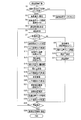
- the component mounting work by the mounting module 12a is a work that constitutes at least a part of the electric circuit manufacturing work, and is a work as shown in the flowchart of FIG.
- This component mounting operation is performed by a control device (see FIG. 13) that controls the mounting module 12a executing a component mounting program.
- the control device includes a substrate conveyor device 18, a component feeder 20, a base fixed component camera 22, a mounting head 24b (working head 24), a head moving device 26, a camera moving device 64 of the imaging unit 60, and
- Each device such as the vertical view camera 62 (component camera 78 and board camera 80) is configured to operate under its own control.
- step 1 (abbreviated as “S1”. The other steps are similarly omitted), whether or not a lot change has been performed on a board on which a component mounting operation will be performed will be described later. It is determined whether or not a lot change has been made for any of these (for example, whether or not a new component holding tape has been supplied) and whether or not the suction nozzle 52 of the mounting head 24b has been replaced. Information on the fact of changing the lot of substrates, changing the lot of parts, and replacing the suction nozzle 52 is sent to the control device of the mounting module 12a, and based on the information, the judgment is made. The If it is determined that any one of the substrate lot change, the component lot change, and the suction nozzle 52 replacement has been performed, the process of S2 is executed. Since the process of S2 will be described later, a description thereof is omitted here.
- the board used for component mounting work is carried in from the upstream side by the board conveyor device 18, and the board is fixed at a predetermined work position.
- each of a plurality of substrate reference marks (fiducial marks) attached to the substrate is detected by the substrate camera 80 that constitutes the vertical view camera 60 of the imaging unit 60 disposed on the X slide 42. Imaged. More specifically, first, the lower light-receiving unit 76 of the vertical-view camera 60 that is positioned at the retracted position by the head moving device 26 by the forward / backward moving mechanism 82 of the camera moving device 64 includes each of the plurality of substrate reference marks.
- the mounting head 24b is moved by the head moving device 26 so as to be sequentially positioned above (directly above), and at each of the positions, the substrate camera 80 images each of the plurality of substrate reference marks. .
- the height of the vertical view camera 60 is adjusted by the vertical displacement mechanism 84 of the camera moving device 64 so that the focus of the substrate camera 80 matches the surface of the substrate.
- a coordinate system hereinafter, referred to as a reference for the position on the board used for mounting components on the board. May be referred to as a “substrate coordinate system”. This method of determining the substrate coordinate system is a general method and will not be described here.
- one component to be mounted next is sucked and held by the suction nozzle 52 in accordance with the mounting order set by the program.
- the mounting head 24b is moved by the head moving device 26 to a position where the suction nozzle 52 is positioned directly above the component supply portion of the component feeder 20 that supplies the component to be mounted.
- the mounting head 24b is actuated to lower the tip of the suction nozzle 52 to a height position where it contacts the upper surface of the component, and negative pressure is supplied to the suction nozzle 52 to hold the component by suction.
- the suction nozzle 52 holding the component is raised to a predetermined height position.
- step S8 when moving the component sucked and held by the suction nozzle 52 from above the component feeder 20 to above the substrate, the head passes so that the component passes above the base fixed component camera 22.
- the mounting head 24 b is moved by the moving device 26. During the movement, a component is imaged from below by the component camera 22 at a position where the nozzle axis of the suction nozzle 52 coincides with the axis of the component camera 22. That is, imaging data of the lower surface image of the component is acquired.
- the positional deviation amount (relative positional deviation amount) of the component with respect to the nozzle axis is grasped based on the imaging data. More specifically, the center of the part is obtained based on the contour of the part in the lower surface image, and the relative positional deviation amount between the center and the nozzle axis line is grasped.
- the correction amount for the mounting position in the substrate coordinate system is determined based on the relative positional deviation amount.
- the various misalignment amounts described below, including the relative misalignment amount are the misalignment amount in each of the X direction and the Y direction, and the misalignment amount with respect to the azimuth, that is, the misalignment amount in the rotational direction (deviation angle).
- the correction amount for the mounting position is also the amount by which the component is shifted in each of the X direction and the Y direction during mounting and the amount by which the component is shifted in the rotation direction (azimuth), that is, the suction nozzle 52 is rotated.
- the amount of rotation (angle) of the part is also the head moving device 26 and the mounting head 24b are operated based on the correction amount so that the component is positioned at a predetermined mounting position in the board coordinate system, and is sucked and held at that position.
- the suction nozzle 52 is lowered to a height position where the lower surface of the component contacts the substrate surface based on the thickness of the component, and the supply of negative pressure is cut off, so that the component is mounted on the substrate. Placed in position.
- This component mounting operation is a general operation. When the component is not a required component, correction of the mounting position as described above, that is, correction based on imaging data of the component by the base fixed component camera 22 is performed. As a result, the mounting accuracy required for the component is sufficiently secured.
- the nozzle axis of the suction nozzle 52 is mounted so that the component held by the suction nozzle 52 is positioned above the portion (mounting portion) of the substrate surface to be mounted in the substrate coordinate system.
- the mounting head 24b is moved and fixed by the head moving device 26 so as to coincide with the center of the part.
- the front / rear direction advance / retreat mechanism of the camera moving device 64 is operated, and the vertical view camera 62 is positioned at the holder lower position.
- the optical axes of the component camera 78 and the board camera 80 are made to coincide with the center of the mounting portion and the nozzle axis.
- the board mounting part is imaged by the board camera 80, and the imaging data of the mounting part, more specifically, the land imaging data formed in the mounting part is acquired, and in S15
- the component picked up and held by the suction nozzle 52 by the component camera 78 is imaged, and the imaging data of the bumps on the lower surface of the component, more specifically, the bump on the lower surface of the component is acquired.
- a component lower surface imaging data acquisition step for acquiring imaging data of the lower surface of the component is performed.
- the height position of the vertical view camera 62 is adjusted by the vertical displacement mechanism 84 so that the focus of the board camera 80 and the focus of the component camera 78 are matched to the surface of the board and the bottom surface of the component, respectively. Is adjusted.
- the image of the mounting part based on the imaging data obtained as a result of imaging by the board camera 80 includes an image of the land L formed on the surface of the board S.
- the image of the lower surface of the component based on the shooting data obtained as a result of imaging by the camera 78 includes an image of the bump B included in the component P.
- the component P shown in the figure has six bumps B, and six lands L on which the six bumps B are respectively placed are formed in the mounting site shown in the figure.
- the six bumps B are considered to be integrated and are called “bump patterns” composed of the six bumps B, and the six lands L are considered to be integrated.
- the image of the lower surface of the component P shown in FIG. 10 is obtained by inverting the actually obtained image in order to represent the positions of the component P and the bump B in the substrate coordinate system.
- the relative positional deviation amount between the mounting part of the substrate and the component held by the suction nozzle 52 is the relative positional deviation amount between the bump and the land, more specifically, the bump pattern. And the relative positional deviation amount between the land pattern and the land pattern.
- the center of the mounting portion in the board coordinate system and the optical axis of the board camera 80 coincide with each other. If the explanation is made with reference to the image of the land L shown in FIG. The amount of deviation of the land pattern in the substrate coordinate system with reference to is recognized.
- the amount of deviation includes the amount of deviation in the X direction (X direction land deviation amount) ⁇ x L , the amount of deviation in the Y direction (Y direction land deviation amount) ⁇ y L , and the amount of deviation in the rotational direction (rotation direction land deviation amount) ⁇ . It is recognized as the amount of land deviation ( ⁇ x L , ⁇ y L , ⁇ L ) with L as a parameter.
- the nozzle axis line in the substrate coordinate system and the optical axis line of the component camera 78 coincide with each other, and the land pattern shift can be described with reference to the image of the bump B shown in FIG.
- a deviation amount of the bump pattern in the substrate coordinate system with the image center O as a reference is recognized. Similar to the amount of deviation of the bump pattern, this amount of deviation is the amount of deviation in the X direction (X direction bump deviation amount) ⁇ x B , the amount of deviation in the Y direction (Y direction bump deviation amount) ⁇ y B , and the amount of deviation in the rotational direction (rotation direction). It is recognized as a bump deviation amount ( ⁇ x B , ⁇ y B , ⁇ B ) with a bump deviation amount ⁇ B as a parameter.
- the relative deviation amount of the bump pattern with respect to the land pattern is equal to the bump / land relative deviation amount ( ⁇ x BL , ⁇ y BL , ⁇ BL). ) As follows.
- the contour (outer shape) of the component P is further specified based on the shooting data obtained as a result of imaging by the component camera 78, and the relative deviation amount between the specified contour and the bump B is grasped.
- the deviation of the bump pattern in the component P is grasped.
- the bump B in a state where the bump pattern is not shifted is indicated by a white circle, and actually, the bump pattern is shifted such that the bump B is indicated by a black circle, for example.
- the deviation of the bump pattern is unavoidable in manufacturing, and the confirmation of the mounting position of the mounting position after component mounting described later cannot recognize the bump, and the outer shape of the component P, that is, the contour is not recognized. Only relying confirmation can be made.
- the amount of relative deviation between the contour of the component P and the bump B is grasped prior to confirmation of the mounting position.
- the deviation amount of the contour of the component P with reference to the image center O shown in FIG. 10 is recognized as the component deviation amount ( ⁇ x P , ⁇ y P , ⁇ P ), and the component deviation amount ( ⁇ x P , [Delta] y P, the amount Banpuzure that are certified as previously ⁇ P) ( ⁇ X B, ⁇ Y B, based on the [Delta] [theta] B), the contour deviation of the component P with respect to the bump pattern in the coordinate system relative to the bump pattern center O B
- the amount of component / bump relative deviation ( ⁇ x PB , ⁇ y) whose parameters are X direction component / bump relative deviation amount ⁇ x PB , Y direction component / bump relative deviation amount ⁇ y PB , rotational direction component / bump relative deviation amount ⁇ PB PB , ⁇ PB ).
- a deviation amount grasping step for grasping the relative position deviation amount between the contour of the component and the bump is performed.
- the above-described method for obtaining the X-direction component / bump relative deviation amount is a method using a trigonometric function. However, since the method is purely mathematical, description thereof is omitted here.
- correction amounts ( ⁇ X, ⁇ Y, ⁇ ) for component mounting are determined.
- This correction amount uses the X direction correction amount ⁇ X, the Y direction correction amount ⁇ Y, and the rotation direction correction amount ⁇ as parameters, and the determination thereof is performed by determining the bump / land relative deviation amount ( ⁇ x BL , Based on [Delta] yBL , [Delta] [theta] BL ), it is performed by referring to the data relating to the mounting position confirmed for the mounting of the same component to the same mounting site performed so far.
- a reference correction amount ( ⁇ X 0 , ⁇ Y 0 , ⁇ 0 ) for placing each bump on each land without deviation is determined based on the bump / land relative deviation amount, and the component is positioned above the mounting site. Even if the suction nozzle 52 is lowered and the component is mounted after performing the correction operation based on the reference correction amount, the mounting position of the mounted component is slightly shifted. Specifically, even if a component mounting operation including a correction operation based on the bump / land relative misalignment amount is performed, the nozzle axis is slightly inclined, the tip of the suction nozzle 52 is displaced from the nozzle axis (bend of the nozzle), and suction is performed.
- the present mounting module 12a referring to the result of mounting performed so far, that is, the actually confirmed mounting position shift amount, the X-direction shift tendency amount ⁇ x 0 , the Y-direction shift tendency amount ⁇ y 0 , A deviation tendency amount ( ⁇ x 0 , ⁇ y 0 , ⁇ 0 ) using the rotational direction deviation tendency amount ⁇ 0 as a parameter is recognized, and the recognized deviation tendency amount and the bump / land relative deviation amount ( ⁇ x BL , ⁇ y BL , ⁇ ).
- X direction correction amount ⁇ X 0 ⁇ x 0
- the reference correction amounts ( ⁇ X 0 , ⁇ Y 0 , ⁇ 0 ) are also determined according to a mathematical method using a trigonometric function. However, since the determination method is also a pure mathematical method, the description here will be given. Is omitted.
- the mounting position shift amounts ( ⁇ x, ⁇ y, ⁇ ) using the X direction mounting position shift amount ⁇ x, the Y direction mounting position shift amount ⁇ y, and the rotational direction mounting position shift amount ⁇ confirmed in the previous mounting as parameters are related to the mounting position.
- Data mounting position related data
- the stored data is subjected to processing according to a statistical method to obtain the above deviation tendency amount ( ⁇ x 0 , ⁇ y 0 , ⁇ 0 ⁇ ).
- the present mounting module 12a averages the X-direction mounting position deviation amount ⁇ x, the Y-direction positional deviation amount ⁇ y, and the rotational-direction positional deviation amount ⁇ with respect to each previous mounting.
- the deviation tendency amount ( ⁇ x 0 , ⁇ y 0 , ⁇ 0 ⁇ ) is determined.
- the tendency of displacement of the mounting position is affected and changed by changing the lot of the substrate, changing the lot of the components, and replacing the suction nozzle 52 in view of the cause of the deviation described above.
- the mounting position related data in the previous mounting and the current certification regarding the component mounting that will be affected by the change or replacement. It is desirable to newly recognize the deviation tendency amount based on the subsequent new mounting position related data without using the deviation tendency amount.
- the mounting position related data stored in the mounting position related data storage unit and the deviation tendency amount currently recognized are updated. Specifically, it is cleared, that is, reset.
- the vertical view camera 62 at the holder lower position is moved backward to the retracted position by the forward / backward moving mechanism 82.
- a component mounting process that is, a component mounting operation including a correction operation is performed. More specifically, first, the mounting head 24b is moved by the head moving device 26 by the X direction correction amount ⁇ X and the Y direction correction amount ⁇ Y, and the suction nozzle 52 is rotated in the rotation direction by the nozzle rotating device of the mounting head 24b.
- the mounting position is corrected, and thereafter, the suction nozzle 52 is lowered to a height position where the lower surface of the component is located on the substrate surface, and the suction nozzle 52 is moved to that position.
- the suction nozzle 52 is lowered to a height position where the lower surface of the component is located on the substrate surface, and the suction nozzle 52 is moved to that position.
- the vertical view camera 62 is advanced to the holder lower position by the forward / backward moving mechanism 82 without moving the mounting head 24b.
- the height position of the vertical view camera 62 is adjusted by the vertical displacement mechanism so that the upper surface of the mounted component is in focus with the upper surface of the mounted component, and then the substrate camera 80 is mounted in S21.
- the captured part is imaged, and imaging data of the part is acquired. That is, in S21, a component upper surface imaging data acquisition step for acquiring imaging data of the upper surface of the mounted component is performed.
- the above-described shift tendency amount ( ⁇ x 0 , ⁇ y 0 , ⁇ 0 ⁇ ) is (0, 0, 0).
- the correction amounts ( ⁇ X, ⁇ Y, ⁇ ) are the above-described reference correction amounts ( ⁇ X 0 , ⁇ Y 0 , ⁇ 0 ).
- the image of the part based on the shooting data obtained as a result of imaging by the board camera 80 is That is, the image of the component located at the normal position is an image as shown in FIG. The image center O of this image coincides with the nozzle axis in the state where the correction operation has been performed.
- the bump pattern of the component P is in the X direction in the substrate coordinate system based on the image center O.
- they are defined as bump reference normal state index quantities ⁇ f ( ⁇ X 0 ), f ( ⁇ Y 0 ), f ( ⁇ 0 ) ⁇ .
- the X direction bump reference normal state index amount f ( ⁇ X 0 ), the Y direction bump reference normal state index amount f ( ⁇ Y 0 ), and the rotational direction bump reference normal state index amount f ( ⁇ 0 ), which are parameters, are triangular.
- the mounting position of the component cannot be confirmed by the amount of deviation of the bump pattern with respect to ( ⁇ 0 ) ⁇ . That is, in order to confirm the mounting position of the component, it is necessary to rely on the outer shape, that is, the contour of the component P.
- the component / bump relative deviation amounts ( ⁇ x PB , ⁇ y PB , ⁇ PB ) grasped in S 16 are used. In other words, the amount of relative positional deviation between the contour of the component and the bump is taken into account.
- the contour of the component P at the normal position is F ( ⁇ X) in the X direction and F ( ⁇ Y) in the Y direction. ), And can be represented as being in a state shifted to F ( ⁇ ) in the rotation direction, and these are expressed as contour reference normal state index quantities ⁇ F ( ⁇ X 0 ), F ( ⁇ Y 0 ), F ( ⁇ 0 ) ⁇ . It is defined as The component mounting position can be accurately confirmed by the amount of deviation of the component outline with respect to the component reference normal state index amount ⁇ F ( ⁇ X 0 ), F ( ⁇ Y 0 ), F ( ⁇ 0 ) ⁇ . .
- the X direction contour reference normal state index amount F ( ⁇ X 0 ), the Y direction contour reference normal state index amount F ( ⁇ Y 0 ), and the rotation direction contour reference normal state index amount F ( ⁇ 0 ), which are parameters, are also triangular. Although it is calculated
- the image of the component based on the imaging data acquired and acquired in S21 is actually as shown in FIG.
- the component P mounted at the normal position is indicated by a two-dot chain line, and it can be seen that the actual component P indicated by the solid line is mounted on the substrate in a state shifted from the normal position.
- the mounting position confirmation processing in S22 first, the mounting position of the component is specified based on the contour of the component P.
- This identification, mounting position to Paramemeta parts contour center O P in the X direction mounting position indicating amount x, Y-direction mounting position indicating amount y and rotational mounting position indicating amount ⁇ in the substrate coordinate system based on the image center O This is done by specifying the index amount (x, y, ⁇ ).
- the mounting position index amount (x, y, ⁇ ) and the contour reference normal state index amount ⁇ F ( ⁇ X 0 ), F ( ⁇ Y 0 ), F ( ⁇ 0 ) ⁇ Accordingly, the above-described mounting position deviation amounts ( ⁇ x, ⁇ y, ⁇ ) are recognized.
- Rotation direction mounting position deviation amount: ⁇ ⁇ -F ( ⁇ 0 )
- the recognized mounting position shift amounts ( ⁇ x, ⁇ y, ⁇ ) are stored in the mounting position related data storage unit as mounting position related data. As described above, this data is used to identify the deviation tendency amounts ( ⁇ x 0 , ⁇ y 0 , ⁇ 0 ).
- the vertical view camera 62 is retracted to the retracted position by the forward / backward moving mechanism 82.
- S25 it is determined whether or not the currently mounted component is the last component to be mounted on the board. If it is determined that the component is not the last component, the process returns to S6 and the next Installation of parts is started. If it is the last component, in step S26, the substrate is unfixed by the substrate conveyor device 18, and the substrate on which the component mounting operation by the mounting module 12a is completed is carried out downstream.
- the above description regarding the component mounting operation was performed on the mounting module 12a to which the mounting head 24b is mounted.
- the component mounting operation is performed by the mounting module 12a to which the mounting head 24a which is the index type mounting head 24 is mounted, the number of components corresponding to the number of the suction nozzles 48 is sucked and held in S6, and the base in S8
- the steps S7 to S24 (excluding S8) are repeatedly executed as many times as the number of the held components.
- the component mounting result by the mounting module 12a is inspected by the inspection module 12b (see FIG. 1) described above. In the inspection, naturally, the mounting position of the required precision component, that is, the bumped component is also confirmed.
- an imaging head 24c (see FIG. 4) is attached to the inspection module 12b in place of the mounting head 24b, and the mounting component imaged by the board camera 90 included in the imaging head 24c is attached. Based on the imaging data, the inspection module 12b confirms the mounting position of the bumped component.
- the image of the component with bumps based on this imaging data is the same image as FIG. 12, and neither the bump nor the land on which the bump is placed can be recognized.
- the confirmation processing of the mounting position of the bumped component by the inspection module 12b is performed by a method similar to the method performed in S22. Specifically, based on the mounting position index amount (x, y, ⁇ ) of the component to be checked and the component / bump relative shift amount ( ⁇ x PB , ⁇ y PB , ⁇ PB ), the mounting position shift amount ( ( ⁇ x, ⁇ y, ⁇ ) are recognized, and whether or not the bumped component is mounted is determined based on the certified mounting position shift amount. That is, also in the inspection module 12b, a mounting position confirmation process is performed in which the mounting position of the component on the board is checked while taking into account the relative positional deviation between the contour of the component and the bump.
- the control device of the mounting module 12b and the control device of the inspection module 12b are capable of data communication with each other, and the component / bump relative misalignment grasped by the mounting module 12a is transmitted to the inspection module 12b and transmitted.
- the component / bump relative misalignment amount used is used in the confirmation process.
- the mounting module 12a is controlled by a control device on which the mounting module 12a is mounted.
- the control device includes a computer, an image processing unit that functions as an imaging data processing device, and the like as main components. However, in view of the component mounting operation executed as described above, as shown in FIG. It can be considered that various functional units are provided.
- a substrate fixing / conveying control unit 102 is provided as a functional unit for controlling the substrate conveyor device 18.
- the control device 100 includes a component supply control unit 104 as a functional unit that controls the component feeder 20 in order to supply the component held by the suction nozzle 52 (48) in S6 at a predetermined supply site.
- a mounting control unit 106 is provided as a functional unit for controlling the mounting head 24b (24a) and the head moving device 26 to perform a component mounting operation.
- the mounting control unit 106 mounts the component held by the suction nozzle 52 on the substrate while performing the correction operation, that is, performs the component mounting operation of S11 and S19. It has many functions including the function of controlling the moving device 26. Specifically, in S4, S6, S8, S12, etc., control related to the mounting head 24b (24a) and the head moving device 26, such as control for moving the mounting head 24b and raising / lowering the suction nozzle 52, etc. It has a function to execute widely.
- the control device 100 fixes the imaging unit 60 and the base in order to take an image of the board mounting site, the components held by the suction nozzle, and the like before the component mounting operation.
- a pre-mounting imaging control unit 108 as a functional unit for controlling the camera 22 and the like, and in S21, S22, and S24, an imaging unit 60 for imaging components mounted on the board after the component mounting operation.
- a post-mounting imaging control unit 110 is provided as a functional unit to be controlled.
- the pre-mounting imaging control unit 108 and the post-mounting imaging control unit 110 also have a function of receiving imaging data from the component camera 78, the board camera 80, and the base fixed type component camera 22.
- control device 100 includes a displacement amount grasping unit 112 and a mounting position confirming unit 114 as functional units centered on the image processing unit.
- the deviation amount grasping unit 112 is based on the imaging data received from the component camera 78, the board camera 80, and the base fixed type part camera 22, and the relative positional deviation amount between the board mounting part and the part.
- the mounting position confirmation unit 114 confirms the mounting position of the mounted component, for example, in S22 by recognizing the displacement amount of the mounting position in S22. Part.
- the control device 100 determines the correction amount for the correction operation in S11 and S17 based on the relative positional deviation amount between the board and the component grasped by the deviation amount grasping unit 112 in S10 and S17.
- a correction amount determination unit 116 is provided as a functional unit.
- the correction amount determination unit 116 has a function of determining the correction amount in consideration of the tendency of the component mounting position shift, such as a mounting position shift amount that is data referred to at that time.
- a mounting position related data storage unit 118 is provided as a functional unit for storing the mounting position related data. The mounting position related data is obtained at the time of confirmation by the mounting position confirmation unit 114, and is sent from the mounting position confirmation unit 114 to the mounting position related data storage unit 118.
Abstract
実用性の高い電気部品装着機および電気回路製造方法を提供する。電気部品装着機において、部品カメラおよび基板カメラとして機能する上下視野カメラ62を支持して、それを、吸着ノズル52の下方に位置する位置と退避位置との間で移動させるカメラ移動装置64を、装着ヘッド24bと一体的に移動する箇所に配設する。部品Pが基板Sの装着部位の上方に位置する状態で、部品および装着部位を撮像できるため、装着精度が向上する。また、電気回路製造方法において、バンプBを有する部品を撮像してその部品の輪郭とバンプとの相対位置ズレ量を把握し、その相対位置ズレ量を加味して、装着後における部品の装着位置の確認を行う。装着後にはバンプが認識できないが、上記ズレ量を加味することで、部品の輪郭に基づいて、装着位置の確認を精度よく行うことができる。
Description
本発明は、電気部品を回路基板に装着する電気部品装着機、および、電気部品を回路基板に装着することによって電気回路を製造する電気回路製造方法に関する。
電気回路の製造は、電気部品を回路基板に装着して行われる。電気部品の装着精度の向上を目的として、この電気部品の装着(以下、「部品装着」と略す場合がある)の際には、例えば、下記特許文献に記載されているように、装着ヘッドに保持された電気部品を下方から部品撮像装置によって撮像するとともに、基板固定装置によって固定された基板の表面に付された基板基準マークを基板撮像装置によって撮像し、それらの撮像によって得られた撮像データを基に、その回路基板における適正な装着位置にその電気部品が装着される。また、部品装着の後、その装着位置を確認することも行われる。
より高い精度が部品装着に求められる中、発明者は、上述した電気部品,回路基板表面の撮像に関する手法や装着位置の確認に関する手法を改善することで、電気部品装着機や電気回路製造方法の実用性を高めることができるとの知見を得た。本発明は、この知見に基づくものであり、実用性の高い電気部品装着機および電気回路製造方法を提供することを課題とする。
上記課題を解決するため、本発明の電気部品装着機は、所定の撮像装置移動装置、つまり、装着ヘッド若しくはその装着ヘッドが取り付けられた部分に配設されるとともに、少なくとも基板撮像装置と部品撮像装置との一方を支持し、その一方を、それが部品保持具の下方に位置する保持具下方位置と、その位置から退避させられた退避位置との間で移動可能な撮像装置移動装置を備えたことを特徴とする。
また、上記課題を解決するため、本発明の電気回路製造方法は、バンプを有する電気部品を撮像してその電気部品の輪郭とバンプとの相対位置ズレ量を把握し、その相対位置ズレ量を加味して、装着後における電気部品の装着位置の確認を行うことを特徴とする。
上記本発明の電気部品装着機によれば、回路基板の装着部位の上方に電気部品が位置する状態において、その装着部位の上方からの撮像データと電気部品の下方からの撮像データとの少なくとも一方を取得することができ、撮像データの取得後に基板撮像装置と部品撮像装置との一方を退避させることで、装着ヘッドをヘッド移動装置によって移動させることなく、取得した撮像データに基づいてその電気部品をその装着部位に装着することができる。その結果、精度の高い部品装着を行うことが可能となる。さらに、本発明の電気部品装着機では、部品保持具を基板固定装置によって固定された回路基板の装着部位の上方に移動させる際、撮像装置移動装置に支持された基板撮像装置と部品撮像装置との一方が、装着ヘッドとともにヘッド移動装置によって移動させられ、その移動させられた状態において、撮像装置移動装置によって、保持具下方位置と退避位置との間で移動させることで、基板撮像装置と部品撮像装置との一方を適正に保持具下方位置に位置させることが可能となる。そのことは、部品装着の精度を高めることに寄与している。
また、本発明の電気部品製造方法によれば、下面にバンプを有する電気部品に対して、装着前に把握した輪郭とバンプとの相対位置ズレ量を加味することで、装着後にそれの輪郭に基づいた装着位置の確認を精度よく行うことができる。
以下に、本願において特許請求が可能と認識されている発明(以下、「請求可能発明」という場合がある)の態様をいくつか例示し、それらについて説明する。各態様は請求項と同様に、項に区分し、各項に番号を付し、必要に応じて他の項の番号を引用する形式で記載する。これは、あくまでも請求可能発明の理解を容易にするためであり、それらの発明を構成する構成要素の組み合わせを、以下の各項に記載されたものに限定する趣旨ではない。つまり、請求可能発明は、各項に付随する記載,実施例の記載等を参酌して解釈されるべきであり、その解釈に従う限りにおいて、各項の態様にさらに他の構成要素を付加した態様も、また、各項の態様から何某かの構成要素を削除した態様も、請求可能発明の一態様となり得るのである。そして、請求可能発明の態様のうちのいくつかのものが、特許請求の範囲に記載した請求項に係る発明に相当する。
具体的には、(2)項が請求項1に、(4)項が請求項2に、(7)項が請求項3に、(8)項が請求項4に、(9)項が請求項5に、(10)項が請求項6に、(11)項が請求項7に、それぞれ相当し、(21)項が請求項8に相当する。
(1)回路基板を固定する基板固定装置と、
電気部品を保持する部品保持具を有し、その部品保持具によって保持された電気部品を前記基板固定装置に固定された回路基板上に装着するための装着ヘッドと、
その装着ヘッドが取り付けられたヘッド取付体と、
そのヘッド取付体を移動させることによって、前記基板固定装置に固定された回路基板の表面に沿って前記装着ヘッドを移動させるヘッド移動装置と、
前記基板固定装置に固定された回路基板の表面をその回路基板の上方から撮像するための基板撮像装置と、
前記装着ヘッドが有する前記部品保持具に保持された電気部品をそれの下方から撮像するための部品撮像装置と
少なくとも前記基板撮像装置と前記部品撮像装置との一方を支持するとともに、その一方を、それが前記部品保持具の下方に位置する保持具下方位置と、その位置から退避させられた退避位置との間で移動可能な撮像装置移動装置と
を備えた電気部品装着機。
本項の電気部品装着機は、例えば、基板固定装置によって固定された回路基板の任意の部位の上方に部品保持具によって保持された電気部品が位置する状態において、基板撮像装置と部品撮像装置との一方を、上記保持具下方位置、つまり、回路基板の上記部位と部品保持具に保持された電気部品との間に位置させるように構成することが可能である。そのように構成することで、後に説明するように、回路基板におけるその電気部品が装着される部位(以下、「装着部位」)の上方に電気部品が位置する状態において、その装着部位の上方からの撮像データ若しくは電気部品の下方からの撮像データを取得することができ、そして、撮像データの取得後に基板撮像装置と部品撮像装置との一方を退避させることで、装着ヘッドをヘッド移動装置によって移動させることなく、取得した撮像データに基づいてその電気部品をその装着部位に装着することができる。その結果、精度の高い部品装着を行うことが可能となる。後に説明する複数のバンプを備える電気部品のように、特に高い装着精度が要求される電気部品を装着する場合に、有効である。
なお、本項に記載の「撮像装置移動装置」は、後に説明するように、基板撮像装置と部品撮像装置との両方を支持するものであってもよい。撮像装置移動装置が基板撮像装置のみを支持する場合、本項の電気部品装着機は、部品撮像装置が当該電気部品装着機のいずれかの箇所に固定されているように構成することができ、また、部品撮像装置のみを支持する場合、基板撮像装置が、上記装着ヘッド若しくはヘッド取付体に固定されているように構成することができる。また、本項の電気部品装着機は、2以上の基板撮像装置若しくは2以上の部品撮像装置を備える場合、それらの1つのみが撮像装置移動装置によって支持されて、保持具下方位置に移動させられるように構成することができる。
また、「撮像装置移動装置」は、基板撮像装置と部品撮像装置との一方(以下、「一方の撮像装置」といい、他方を「他方の撮像装置」と言う場合がある)を一方向にのみ移動させるものであってもよく、例えば、XY型移動装置のように、一平面内において任意の方向に移動させるものであってもよい。一方向にのみ移動させる場合、直線的に移動させてもよく、いずれかの位置を中心として回動させるように移動させてもよい。さらに、「撮像装置移動装置」は、1つの上記保持具下方位置に対して、その保持具下方位置と相対的に上記退避位置が1つだけ設定され、一方の撮像装置を、それら保持具下方位置と退避位置との間で移動させるように構成されてもよく、また、その保持具下方位置に対して複数設定された若しくは任意の位置となり得る退避位置との間で移動させるように構成されていてもよい。さらに、装着ヘッドが複数の電気部品保持具を有するような場合には、その複数の電気部品保持具に対応して複数設定された保持具下方位置と、退避位置との間で、一方の撮像装置を移動させるように構成されていてもよい。なお、「撮像装置を部品保持具の下方に位置させる」とは、厳密には、その撮像装置の受光部を部品保持具の下方に位置させることを意味する。
(2)前記撮像装置移動装置が、
前記装着ヘッドまたは前記ヘッド取付体に配設された(1)項に記載の電気部品装着機。
前記装着ヘッドまたは前記ヘッド取付体に配設された(1)項に記載の電気部品装着機。
本項の電気部品装着機では、装着ヘッドがヘッド移動装置によって移動させられることで、部品保持具に保持された電気部品が、装着部位の上方に位置させられ、その状態において、撮像装置移動装置は、一方の撮像装置を、装着ヘッドに対して移動させることによって、保持具下方位置と退避位置との間で移動させることができる。ヘッド移動装置は、例えば、XYロボット型の移動装置である場合、一般に、装着ヘッドをX方向若しくはY方向に移動させるボールねじ機構が採用される。このボールねじ機構を構成するねじロッドの微妙な曲がりや螺子ピッチの位置によるばらつき等により、電気部品を装着部位の上方に位置させた場合であっても、適正な位置からはある程度のズレが生じる可能性がある。また、同様に、撮像装置移動装置が、ヘッド移動装置とは別のXYロボット型の移動装置であった場合には、保持具下方位置に一方の撮像装置を位置させた場合であっても、適正な位置からはある程度のズレが生じる可能性がある。本項の電気部品装着機では、部品保持具を基板固定装置によって固定された回路基板の装着部位の上方に移動させる際、撮像装置移動装置に支持された一方の撮像装置が、装着ヘッドとともにヘッド移動装置によって移動させられ、その移動させられた状態において、撮像装置移動装置によって、保持具下方位置と退避位置との間で移動させれば、一方の撮像装置を適正な保持具下方位置に位置させることが可能となる。端的に言えば、部品保持具が、回路基板のいずれの部位の上方に位置する場合であっても、例えばその部品保持具の直下(真下)に、一方の撮像装置を位置させることができるのである。そのことは、電気部品の装着精度を高めることに寄与している。なお、装着ヘッドがヘッド取付体に交換可能に取り付けられるものである場合には、いずれの装着ヘッドについても撮像装置が共通化させられるという利点を考慮して、撮像装置移動装置がヘッド取付体に配設されることが望ましい。
(3)前記撮像装置移動装置が、
前記基板撮像装置と部品撮像装置との一方を、その一方が前記保持具下方位置に位置する状態において、上下方向に変位可能な上下方向変位機構を有する(1)項または(2)項に記載の電気部品装着機。
前記基板撮像装置と部品撮像装置との一方を、その一方が前記保持具下方位置に位置する状態において、上下方向に変位可能な上下方向変位機構を有する(1)項または(2)項に記載の電気部品装着機。
本項の電気部品装着機は、一方の撮像装置による撮像において、装着部位の高さ(レベル)の相違,電気部品の厚さの相違等に容易に対処できることから、利便性に優れる。具体的な例を挙げて詳しく説明すれば、撮像装置移動装置に支持された一方の撮像装置は、保持具下方位置に位置させられる場合、部品保持具によって保持された電気部品と、基板固定装置によって固定された回路基板との間に位置することになる。したがって、それら電気部品と回路基板との間隔は比較的小さいことから、一方の撮像装置は、コンパクトなものであることが要求される。この要求の下、一方の撮像装置は、焦点距離の調節が不能な撮像装置、つまり、固定焦点型の撮像装置とせざるを得ない場合がある。このような撮像装置であっても、上記上下方向変位機構により、高さの異なる装着部位や、厚さの異なる電気部品に対して、ピントの合った画像の撮像データを得ることが可能となる。なお、「上下方向変位機構」は、一方の撮像装置が保持具下方位置に位置するときにだけ上下方向に変位するように構成されてもよく、また、保持具下方位置と退避位置との間のいずれの位置においても上下方向に変位するように構成されてもよい。
(4)前記撮像装置移動装置が、前記基板撮像装置と前記部品撮像装置との他方をも支持するとともに、その他方を、それが前記部品保持具の下方に位置する保持具下方位置と、その位置から退避させられた退避位置との間で移動させるように構成された(1)項ないし(3)項のいずれか1つに記載の電気部品装着機。
本項の電気部品装着機は、部品保持具によって保持された電気部品が、基板固定装置によって固定された回路基板における装着部位の上方に位置する状態において、その装着部位の撮像データと、その電気部品の撮像データとの両者を取得することが可能であるため、より実用性が高いものとなる。なお、本項における撮像装置移動装置は、後に説明するように、基板撮像装置と部品撮像装置とを一体的に移動させるようなものであってもよく、また、基板撮像装置を移動させる移動機構と、部品撮像装置を移動させる移動機構とを有して、つまり、2つの移動機構を有して、それらを互いに独立して移動させるものであってもよい。
(5)前記撮像装置移動装置が、前記基板撮像装置と前記部品撮像装置とを一体的に移動させるように構成された(4)項に記載の電気部品装着機。
本項の電気部品装着機は、撮像装置移動装置が、1つの移動機構によって、2つの撮像装置の両者を移動させるように構成された装着機であると解釈することができる。本項の電気部品装着機では、2つの撮像装置自体が一体化されていてもよい。言い換えれば、基板撮像機能と部品撮像機能とを有してあたかも1つの撮像装置として構成された撮像装置を採用することができるのである。具体的には、例えば、それぞれに撮像素子とその撮像素子に結像させるための光路を有する単に2つの撮像装置が互いに固定されたようなものであってもよく、また、例えば、1つの撮像素子と、その撮像素子に対して電気部品,回路基板の各々から結像させる2つの光路と、それら2つの光路を切換える機構とを有するようなものであってもよい。また、後に説明するように、2つ撮像装置に共通して設定された1つの保持具下方位置に、それら2つの撮像装置を一体的に移動させるようなものであってもよく、それら2つ撮像装置に対応して設定された2つの保持具下方位置の各々に、2つの撮像装置を一体的な状態で移動させるようなものであってもよい。
(6)前記基板撮像装置および前記部品撮像装置が、それらの一方が前記保持具下方位置に位置するときに他方も前記保持具下方位置に位置するように、前記撮像装置移動装置に支持された(5)項に記載の電気部品装着機。
本項の電気部品装着機は、先に説明した撮像装置移動装置を、つまり、2つの撮像装置を、それらに共通して設定された1つの保持具下方位置に、それらを一体的に移動させるような撮像装置移動装置を備えた部品装着機であると考えることができる。本項に記載の基板撮像装置および部品撮像装置は、回路基板,電気部品のそれぞれの撮像においてそれぞれに向かう2つの光軸線が、互いに一致させられていること、つまり、一軸線上において互いに背向するように構成されることが望ましい。
(7)当該電気部品装着機が、当該電気部品装着機の制御を司る制御装置を備え、
その制御装置が、
前記部品保持具によって保持された電気部品が、前記基板固定装置によって固定された回路基板におけるその電気部品が装着される部位である装着部位の上方に位置する状態において、前記撮像装置移動装置を制御して、前記基板撮像装置および前記部品撮像装置の各々を前記保持具下方位置に位置させ、前記基板撮像装置および前記部品撮像装置の各々が前記保持具下方位置に位置する状態において、前記基板撮像装置および前記部品撮像装置を制御して、前記装着部位および前記部品保持具によって保持された電気部品を撮像させる装着前撮像制御部と、
前記基板撮像装置によって撮像された前記装着部位の撮像データと、前記部品撮像装置によって撮像された前記電気部品の撮像データとに基づいて、それら装着部位と電気部品との相対位置ズレ量を把握するズレ量把握部と、
そのズレ量把握部によって把握された前記装着部位と電気部品との相対位置ズレ量に基づいて、その電気部品をその装着部位に装着する際の装着位置についての補正量を決定する補正量決定部と、
前記撮像装置移動装置を制御して、前記基板撮像装置および前記部品撮像装置の各々を前記退避位置に位置させ、前記装着ヘッドおよび前記ヘッド移動装置を制御して、前記補正量決定部によって決定された前記補正量に基づく装着位置の補正を行いつつ、前記部品保持具によって保持された電気部品を前記装着部位に装着する装着制御部と
を有する(4)項ないし(6)項のいずれか1つに記載の電気部品装着機。
本項の電気部品装着機は、実行する部品装着のプロセスに対する限定が加えられた態様の電気部品装着機である。本項の電気部品装着機によれば、先に説明したように、部品保持具によって保持された電気部品が、基板固定装置によって固定された回路基板におけるその電気部品の装着部位の上方に位置する状態において、それら装着部位の撮像データと電気部品の撮像データとの両者が取得可能であり、それらの撮像データに基づいて部品装着が行われるため、高い装着精度の部品装着が可能となる。ちなみに、本項の電気部品装着機は、1つの回路基板に装着される複数の電気部品のすべてに対して、上記プロセスに従った装着が行われることを要さず、例えば、複数の電気部品のうちの高い装着精度が要求されるものにだけ、上記プロセスに従った装着が行われるように構成してもよい。なお、本項を始めとして本明細書に記載されている「装着位置」の概念は、回路基板の表面に沿った方向の位置のみを意味するものではなく、回転位置(方位)をも含む概念であり、同様に、「相対位置ズレ量」は、回路基板の表面に沿った方向の位置ズレのみを意味するものではなく、回転位置ズレ(方位のズレ)をも含む概念である。
(8)前記部品保持具によって保持された電気部品が、下面に1以上のバンプを有するとともに、前記回路基板の前記装着部位に、前記1以上のバンプがそれぞれ載置される1以上のランドが形成されており、
前記ズレ量把握部が、前記装着部位と電気部品との相対位置ズレ量として、前記1以上のランドと前記1以上のバンプとの相対位置ズレ量を把握するように構成された(7)項に記載の電気部品装着機。
前記ズレ量把握部が、前記装着部位と電気部品との相対位置ズレ量として、前記1以上のランドと前記1以上のバンプとの相対位置ズレ量を把握するように構成された(7)項に記載の電気部品装着機。
一般に、バンプを有する電気部品は、高い装着精度を要求される。特に、複数のバンプが小さいピッチで配列されているような電気部品は、装着位置のズレによる短絡(ショート)等の可能性が高く、相当に高い装着精度が要求される。そのことに鑑みれば、本項の電気部品装着装置は、バンプを有する電気部品について、そのバンプとそのバンプが載置されるランドとの相対位置ズレを考慮してその電気部品の装着を行うことができるため、精度の高い装着を実行できることになる。
(9)前記制御装置が、
前記部品保持具によって保持された電気部品が前記装着部位に装着された後に、前記撮像装置移動装置を制御して、前記基板撮像装置を前記保持具下方位置に位置させ、前記基板撮像装置を制御して、前記装着部位に装着された電気部品を撮像させる装着後撮像制御部と、
前記基板撮像装置によって撮像された前記装着部位に装着された電気部品の撮像データに基づいて、その電気部品の装着位置を確認する装着位置確認部と
を有する(7)項または(8)項に記載の電気部品装着機。
前記部品保持具によって保持された電気部品が前記装着部位に装着された後に、前記撮像装置移動装置を制御して、前記基板撮像装置を前記保持具下方位置に位置させ、前記基板撮像装置を制御して、前記装着部位に装着された電気部品を撮像させる装着後撮像制御部と、
前記基板撮像装置によって撮像された前記装着部位に装着された電気部品の撮像データに基づいて、その電気部品の装着位置を確認する装着位置確認部と
を有する(7)項または(8)項に記載の電気部品装着機。
装着部位の上方に電気部品が位置する状態で、回路基板の装着部位と電気部品との相対位置ズレ量を把握し、その相対位置ズレ量に基づく補正を行って装着したとしても、例えば、装着部位の上方から基板表面に電気部品を装着するための動作、つまり、部品装着動作に起因して部品の装着位置がズレる可能性もある。具体的には、部品保持具が若干ではあるが斜めに下降する場合、部品保持具の先端面と回路基板の表面とが若干ではあるが平行でない場合等に、装着位置のズレが発生する。また、部品装着動作の中で行われる補正のための動作、つまり、補正動作に起因して、装着位置がズレる可能性もある。具体的には、部品保持具の先端がその保持具の軸線に対して偏心しているような場合等に、装着位置のズレが発生する。本項の電気部品装着機では、電気部品の装着の後、ヘッド移動装置によって装着ヘッドを移動させることなく、装着前と同じ位置において、回路基板に装着された電気部品を基板撮像装置によって撮像することで、その電気部品の装着位置を精度よく確認できる。したがって、本項の電気部品装着機によれば、そのように行われる装着位置の確認によって、高い装着精度を担保することができるのである。
(10)前記部品保持具によって保持された電気部品が、下面に1以上のバンプを有するとともに、前記回路基板の前記装着部位に、前記1以上のバンプがそれぞれ載置される1以上のランドが形成されており、
前記ズレ量把握部が、前記部品撮像装置によって撮像された前記電気部品の撮像データに基づいて、その電気部品の輪郭と前記1以上のバンプとの相対位置ズレ量をも把握するように構成され、
前記装着位置確認部が、その把握された前記電気部品の輪郭と1以上のバンプとの相対位置ズレ量を加味しつつ、前記装着部位に装着された電気部品の装着位置を確認するように構成された(9)項に記載の電気部品装着機。
前記ズレ量把握部が、前記部品撮像装置によって撮像された前記電気部品の撮像データに基づいて、その電気部品の輪郭と前記1以上のバンプとの相対位置ズレ量をも把握するように構成され、
前記装着位置確認部が、その把握された前記電気部品の輪郭と1以上のバンプとの相対位置ズレ量を加味しつつ、前記装着部位に装着された電気部品の装着位置を確認するように構成された(9)項に記載の電気部品装着機。
先に説明したように、下面にバンプが設けられた電気部品は、そのバンプが回路基板の装着部位に形成されたランドに載置されるように装着される。言い換えれば、バンプが適正な装着位置になっているときに、その電気部品が装着位置が適正であると言える。しかしながら、バンプが電気部品の適正位置に設けられていることは保証し得えず、例えば、電気部品のロットごとにそのバンプの電気部品における位置がばらつくことも考えられる。装着後の基板撮像装置による撮像データに基づく装着位置の確認においては、電気部品の下面のバンプを認識できないことからそれの位置は特定し得ず、専ら電気部品の輪郭を特定して、その電気部品の装着位置が確認される。したがって、電気部品の輪郭とバンプとの相対位置ズレ量を加味することが、装着位置の確認を精度よく行うことに資することとなる。逆に言えば、精度よく装着しても、電気部品の輪郭とバンプとの相対位置ズレ量を加味しなければ、その装着位置が正確であるか否かの判断を、真に適正に行い得ないのである。本項の電気部品装着機では、装着前に、部品撮像装置による撮像データを基に電気部品の輪郭とバンプとの相対位置ズレ量が把握され、その相対位置ズレ量を加味して、基板撮像装置による撮像データに基づく装着位置の確認が行われることから、装着位置の確認を精度よく行うことができる。
(11)前記補正量決定部が、
前回以前に装着された電気部品について前記装着位置確認部によって確認された装着位置に関するデータを参照して、前記補正量を決定するように構成された(9)項または(10)項に記載の電気部品装着機。
前回以前に装着された電気部品について前記装着位置確認部によって確認された装着位置に関するデータを参照して、前記補正量を決定するように構成された(9)項または(10)項に記載の電気部品装着機。
先に説明したように、装着部位の上方に電気部品が位置する状態で、回路基板の装着部位と電気部品との相対位置ズレ量を把握し、その相対位置ズレ量に基づく補正を行って装着したとしても、部品装着動作に起因して、電気部品の装着位置がズレ可能性もある。したがって、その補正を、前回以前に装着が行われた電気部品の装着位置の確認結果を参酌して行うことで、電気部品の装着位置のズレを相当に小さくすることが可能となる。上記確認結果に基づく補正量の決定のための具体的手法は、特に限定されるものではないが、例えば、前回以前に装着行った複数の電気部品の各々の装着位置ズレ量を、平均,重み付け平均等の統計的手法に従って処理し、その処理によって得られた値を、装着位置ズレの傾向を表す値として加味し、補正量を決定すればよい。
(12)前記制御装置が、
電気部品のロット変更,回路基板のロット変更,前記部品保持具の交換のうちの少なくとも1つの事象が発生した場合に、前記補正量決定部が参照する装着位置に関するデータを更新するように構成された(11)項に記載の電気部品装着機。
電気部品のロット変更,回路基板のロット変更,前記部品保持具の交換のうちの少なくとも1つの事象が発生した場合に、前記補正量決定部が参照する装着位置に関するデータを更新するように構成された(11)項に記載の電気部品装着機。
電気部品の装着位置ズレの傾向は、装着条件の変更によって変化する。特に、本項に列挙した事象が発生したとき、つまり、「電気部品のロット」,「回路基板のロット」,「部品保持具」が変わったときに、その傾向がある程度大きく変化する可能性が高い。本項の電気部品装着機は、そのことに配慮し、それらの事象が発生した場合に、参照するデータを変更するようにしている。データの更新の具体的態様は、特に限定されるものではないが、例えば、それらの事象が発生した場合に、それまで参照していたデータを破棄し、それ以後、新たに、参照するデータの蓄積を開始するような態様、つまり、データをリセットするような態様とすることができる。
(21)下面に1以上のバンプを有する電気部品を、撮像装置によって撮像して、その電気部品の下面の撮像データを取得する部品下面撮像データ取得工程と、
その部品下面撮像データ取得工程において取得された前記電気部品の下面の撮像データを基に、撮像データ処理装置によって、その電気部品の輪郭と前記1以上のバンプとの相対位置ズレ量を把握するズレ量把握工程と、
前記1以上のバンプがそれぞれ載置される1以上のランドが形成された回路基板の装着部位に、前記電気部品を装着する部品装着工程と、
その部品装着工程において回路基板に装着された前記電気部品を、撮像装置によって撮像し、その電気部品の上面の撮像データを取得する部品上面撮像データ取得工程と、
その部品上面撮像データ取得工程において取得された前記電気部品の上面の撮像データを基に、撮像データ処理装置によって、前記ズレ量把握工程において把握されたその電気部品の輪郭と1以上のバンプとの相対位置ズレ量を加味しつつ、その電気部品の回路基板に対する装着位置を確認する装着位置確認工程と
を含む電気回路製造方法。
本項の態様は、電気部品を回路基板に装着した後のその電気部品の装着位置の確認に特徴を有する電気回路製造方法に関する態様である。先に説明したように、下面にバンプを有する電気部品は、そのバンプが回路基板の装着部位に設けられたランドに適正に載置されるように装着されるが、装着された後においてそのバンプを認識することができない。したがって、電気部品の輪郭に基づいて装着位置が確認される。本項の電気回路製造方法によれば、電気部品の輪郭とバンプとの相対位置ズレ量を把握しておき、その相対位置ズレ量を加味して装着位置の確認が行われることで、バンプを有する電気部品の装着位置の確認を精度よく行うことができる。なお、本項の電気回路製造方法は、部品装着工程を行う電気部品装着機において装着位置確認工程が行われることを要しない。つまり、部品装着工程を行う電気部品装着機とは別に、装着結果を検査する装着結果検査機を設置し、その検査機によって装着位置確認工程が行われてもよいのである。
以下、請求可能発明を実施するための形態として、請求可能発明の電気部品装着機および電気回路製造方法の実施例を、図を参照しつつ詳しく説明する。なお、請求可能発明は、下記実施例の他、上記〔発明の態様〕の項に記載された形態を始めとして、当業者の知識に基づいて種々の変更、改良を施した種々の形態で実施することができる。
≪電気部品装着システムの構成≫
図1は、実施例の電気部品装着機を含んで構成される電気部品装着システムを示しており、このシステムは、ベースモジュール10と、ベースモジュール10上に並んで配置された8つの作業モジュール12a,12b(以下、「作業モジュール12」と総称する場合がある)とを含んで構成されている。作業に供される回路基板(以下、単に「基板」と言う場合がある)は、上流側(図における手前側)の作業モジュール12から下流側(図における奥側)の作業モジュール12に向かって搬送され、順次、各作業モジュール12による作業が行われ、当該システムによる作業が完了する。ちなみに、本システムでは、8つの作業モジュール12のうちの上流側の7つが、基板に電気部品(以下、単に「部品」と言う場合がある)を装着する装着モジュール12aとされており、最下流に位置する1つものが、装着モジュール12aによる部品装着の結果を検査する検査モジュール12bとされている。7つの装着モジュール12aの各々が、実施例の電気部品装着機として機能し、1つの検査モジュール12bが、装着結果検査機として機能する。なお、このシステムの上流側には、基板の表面にクリームはんだをスクリーン印刷するはんだ印刷機が、下流側には、部品が装着された基板を加熱するためのリフロー炉が、それぞれ配置され、それらによって電気回路製造ラインが構成される。したがって、図に示す電気部品装着システムは、電気回路製造における一部の作業を実行するものとなる。
図1は、実施例の電気部品装着機を含んで構成される電気部品装着システムを示しており、このシステムは、ベースモジュール10と、ベースモジュール10上に並んで配置された8つの作業モジュール12a,12b(以下、「作業モジュール12」と総称する場合がある)とを含んで構成されている。作業に供される回路基板(以下、単に「基板」と言う場合がある)は、上流側(図における手前側)の作業モジュール12から下流側(図における奥側)の作業モジュール12に向かって搬送され、順次、各作業モジュール12による作業が行われ、当該システムによる作業が完了する。ちなみに、本システムでは、8つの作業モジュール12のうちの上流側の7つが、基板に電気部品(以下、単に「部品」と言う場合がある)を装着する装着モジュール12aとされており、最下流に位置する1つものが、装着モジュール12aによる部品装着の結果を検査する検査モジュール12bとされている。7つの装着モジュール12aの各々が、実施例の電気部品装着機として機能し、1つの検査モジュール12bが、装着結果検査機として機能する。なお、このシステムの上流側には、基板の表面にクリームはんだをスクリーン印刷するはんだ印刷機が、下流側には、部品が装着された基板を加熱するためのリフロー炉が、それぞれ配置され、それらによって電気回路製造ラインが構成される。したがって、図に示す電気部品装着システムは、電気回路製造における一部の作業を実行するものとなる。
図2は、外装パネルを外した状態の装着モジュール12aを示しており、この図を参照しつつ説明すれば、装着モジュール12aは、ベース14と、ベース14に上架されたビーム16と、ベース14に配設された基板コンベア装置18と、当該モジュール12aの正面側においてベース14に交換可能に取り付けられてそれぞれが部品供給装置として機能する複数の部品フィーダ20と、基板コンベア装置18と複数の部品フィーダ20との間においてベース14に固定されたベース固定式の部品カメラ22と、複数の部品フィーダ20のいずれかから供給される部品を保持してその部品を基板Sに装着するために離脱させる装着ヘッド24a(「作業ヘッド24」の一種である)と、ビーム16に配設されて装着ヘッド24aを移動させるヘッド移動装置26とを含んで構成されている。
基板コンベア装置18は、基板を搬送するトラック(レーン)を2つ有しており、各トラックに基板を上流側から搬入し、各トラックから下流側に搬出する。基板コンベア装置18は、各トラックの下部に昇降可能な支持テーブルを有しており、所定の位置にまで搬入された基板Sは、上昇した支持テーブルによって支持され、その位置において固定される。つまり、基板コンベア装置18は、装着作業において基板Sを所定の作業位置に固定する基板固定装置として機能する。基板コンベア装置18は、各作業モジュール12に配設されているため、当該システムは、2レーンで部品装着を実施可能とされている。ちなみに、基板コンベア装置18による基板の搬送方向である基板搬送方向は、図に示すX方向(Y方向,Z方向とともに矢印で図示)である。
ヘッド移動装置26は、図3に示すように、いわゆるXY型移動装置であり、Y方向移動装置28とX方向移動装置30とによって構成されている(X方向,Y方向,Z方向は、それぞれ図に矢印で示す)。詳しく説明すれば、Y方向移動装置28は、ビーム16に固定された1対のYガイド32と、1対のYガイド32に案内されるYスライド34と、Yスライド34を移動させるYスライド移動機構36とを含んで構成されている。そして、X方向移動装置30は、Yスライド34に固定された基体38と、基体38に固定された1対のXガイド40と、1対のXガイド40に案内されるXスライド42と、Xスライド42を移動させるXスライド移動機構44とを含んで構成されている。装着ヘッド24aは、ヘッド取付体として機能するXスライド42に、脱着可能に取り付けられている。このような構成により、ヘッド移動装置26は、装着ヘッド24aを、部品フィーダ20の部品供給部位と基板コンベア装置18に固定された基板Sとにまたがって、それらの上方において、その基板Sの表面に沿って(厳密には、基板Sの表面に平行な一平面内において)移動させる(図2を参照のこと)。
装着ヘッド24aは、いわゆるインデックス型の装着ヘッドであり。図4(a)に示すように、それぞれが、部品保持具として機能して負圧の供給(「圧力が大気圧よりも低下させられること」を意味する)によって部品を下端部において吸着保持する8つの吸着ノズル48を有しており、それらは、リボルバ50に保持されている。リボルバ50は、間欠回転し、特定位置(最も正面側の位置)に位置する1の吸着ノズル48が、ノズル昇降装置によって、昇降可能、つまり、上下方向(Z方向)に移動可能とされている。特定位置に位置する吸着ノズル48は、下降した際に、負圧が供給されることによって、部品を保持し、また、負圧の供給が断たれることで、吸着保持している部品を離脱させる。つまり、装着ヘッド24aは、部品フィーダ20にて、順次8つの部品を保持し、基板Sにて、順次8つ部品を装着可能とされているのである。ちなみに、8つの吸着ノズル48の各々は、ノズル回転装置によって、自身の軸線(以下、「ノズル軸線」という場合がある)回りに、つまり、ノズル軸線を中心に回転させられるようになっており、当該装着ヘッド24aは、各吸着ノズル48によって保持されている部品の回転位置(「回転姿勢」,「方位」と言うこともできる)を、変更・調整することが可能とされている。
本作業モジュール12は、作業ヘッド24を交換可能であり、装着ヘッド24a以外の別の種類の作業ヘッド24をも取り付けることができる。図4(b)に示す装着ヘッド24bは、取付可能な作業ヘッド24の一例であり、いわゆるシングルノズル型の装着ヘッドである。この装着ヘッド24bは、部品保持具としての吸着ノズル52が1つだけ設けられている。一度に1つの部品しか吸着保持することができないが、比較的大きな部品をも吸着保持可能とされている。この装着ヘッド24bも、ノズル昇降装置,ノズル回転装置を備えており、吸着ノズル52は、部品の保持・離脱の際に昇降させられ、かつ、部品の回転位置の変更・調整のためにノズル軸線回りに回転させられる。なお、作業ヘッド24の交換は、レバー54の操作によって、ワンタッチで行えるようにされている(図3参照)。
複数の部品フィーダ20の各々は、部品供給装置として機能する。その各々には、部品保持テープ(複数の部品がテープに保持されたものであり、「部品テーピング」とも呼ばれる)が捲回されたリールが、セットされ、各々は、その部品保持テープを間欠的に送り出すことによって、所定の部品供給部位において、順次、部品を1つずつ供給する。なお、装着モジュール12aは、複数の部品フィーダ20に代えて、いわゆるトレイ型の部品供給装置をも取付可能とされている。部品撮像装置として機能するベース固定式の部品カメラ22は、比較的視野の広い固定焦点型のカメラであり、吸着ノズル48(52)によって部品を保持した装着ヘッド24a(24b)が、部品フィーダ20から基板コンベア装置18によって固定された基板Sに移動させられる際に、その部品を下方から撮像する。
装着モジュール12aには、ヘッド取付体として機能する上記Xスライド42の下部に、撮像ユニット60が取り付けられている。撮像ユニット60は、図5に示すように、上下視野カメラ62と、Xスライド42に固定されるとともに上下視野カメラ62を支持しつつ移動させるカメラ移動装置64とを含んで構成されている。上下視野カメラ62は、概して、比較的厚みの小さな直方体形状をなしており、吸着ノズル48に吸着保持された部品をそれの下方から撮像する部品撮像装置としての部品カメラと、基板Sの表面をそれの上方から撮像する基板撮像装置としての基板カメラとが一体化されたものである。
詳しく説明すれば、上下視野カメラ62は、図6に内部構造を示すように、部品カメラ本体66と、基板カメラ本体68と、2対のプリズムセット70とを有し、それらは、筐体72に内蔵されている。上方から上部受光部74を通って受光した光(図の網掛矢印)は、2対のプリズムセット70の一方を構成するプリズム70a,70bによって部品カメラ本体66に導かれ、一方、下方から下部受光部76を通って受光した光(図の白抜矢印)は、2対のプリズムセット70の他方を構成するプリズム70c,70dによって基板カメラ本体68に導かれる。部品カメラ本体66および基板カメラ本体68は、それぞれが固定焦点レンズを有する固定焦点型のカメラであり、それぞれが撮像素子(CCD)を有し、その撮像素子によって得られた信号に基づく撮像データを取得するように構成されている。つまり、上下視野カメラ62では、部品カメラ本体66,プリズム70a,70b,上部受光部74を含んで、部品カメラ78が、基板カメラ本体68,プリズム70c,70d,下部受光部76を含んで、基板カメラ80が、それぞれ構成されているのであり、撮像ユニット60では、それら部品カメラ78と基板カメラ80との両者が、カメラ移動装置64によって支持されているのである。なお、本上下視野カメラ62では、上部受光部74における部品カメラ78の光軸線と、下部受光部76における基板カメラ80の光軸線とが、互いに一致させられている。つまり、上下視野カメラ62は、それら光軸線が一軸線上において互いに背向するように構成されているのである。
撮像装置移動装置として機能するカメラ移動装置64は、図5に示すように、上下視野カメラ62を前後方向(Y方向)に進退させる前後方向進退機構82と、上下方向(Z方向)に変位させる上下方向変位機構84とを含んで構成されている。図示は省略するが、前後方向進退機構82,上下方向変位機構84の各々は、駆動源としての電磁モータを有し、そのモータが制御されることによって任意の位置に上下視野カメラ62を位置させる。具体的には、前後方向進退機構82により、上下視野カメラ62は、部品カメラ78および基板カメラ80の各々が、厳密に言えばそれぞれの受光部である上部受光部74および下部受光部76の各々が、前述の特定位置に位置させられている吸着ノズル48の下方(本装着モジュール12aでは真下)に位置する「保持具下方位置」と、その保持具下方位置から退避すべく最も後退させられた「退避位置」との間で、直線的に進退させられる(図における白抜矢印)。換言すれば、カメラ移動装置64は、部品カメラ78と基板カメラ80に共通して設定された1つの保持具下方位置に、それら部品カメラ78と基板カメラ80を一体的に移動させるように構成されており、部品カメラ78と基板カメラ80との一方が保持具下方位置に位置するときには、他方も保持具下方位置に位置する。ちなみに、図5では、上下視野カメラ62が退避位置に位置する状態が実線で示されており、保持具位置下方位置に位置する状態が2点鎖線で示されている。一方、詳しい説明は省略するが、上下視野カメラ62は、それが前後方向におけるいずれの位置に位置する場合であっても、上下方向変位機構78により、例えば部品カメラ78および基板カメラ80のピント調節を目的として、若干の範囲内において上下に変位させられる(図の太い矢印)。なお、上下視野カメラ62の上部受光部74および下部受光部76の各々を囲むようにして、撮像対象物である部品,基板に対して光を照射するために、LEDを光源とするリングストロボ86が付設されている。
撮像ユニット60を側面から見た図を、図7に示す。この図は、インデックス型の装着ヘッド24aに代えて、シングルノズル型の装着ヘッド24bを取り付けた装着モジュール12aの側面視である。この図においては、図5と同様に、部品カメラ78および基板カメラ80が退避位置に位置する状態が実線で示されており、また、保持具下方位置に位置している状態が2点鎖線で示されている。本撮像ユニット60は、比較的厚みの小さな上下視野カメラ62を採用しているため、図から解るように、装着ノズル52が部品Pを吸着保持した状態で、基板コンベア装置18に固定された基板Sの上方に位置した場合であっても、その部品Pと基板Sとの間において、上下視野カメラ62を、つまり、部品カメラ78および基板カメラ80を、それらの間に介在させることが可能とされている。そして、上下視野カメラ62を後退させて、部品カメラ78および基板カメラ80を退避位置に位置させることによって、吸着ヘッド24bを移動させずに、その場で吸着ノズル52を下降させて部品Pを基板Sに装着することが可能とされている。
本装着モジュール12aは、本撮像ユニット60がヘッド取付体であるXスライド42に配設されているため、いずれの装着ヘッド24a,24bを取り付けた場合であっても、撮像ユニット60を交換することなく、部品カメラ78および基板カメラ80による撮像が可能とされている。言い換えれば、部品カメラ78および基板カメラ80が、いずれの装着ヘッド24a,24bに対しても共通化されており、利便性に優れた装着モジュールとされているのである。ちなみに、装着ヘッド24aを取り付けた場合と、装着ヘッド24bを取り付けた場合とで、保持具下方位置が前後方向において相違することが考えられるが、その相違に対応すべく、カメラ移動装置64は、その相違に応じて保持具下方位置を調整する機能を有している。つまり、前後方向進退機構82は、上下視野カメラ62がいずれの位置に位置されられていても、その位置を保持具下方位置として設定可能に構成されているのである。
検査モジュール12bは、装着ヘッド24aとは異なる作業ヘッド24が取り付けられていること、および、複数の部品フィーダ20が取り付けられていいないことを除き、装着モジュール24aと、略同じ構成とされている。具体的に言えば、検査モジュール12bには、図4(c)に示す撮像ヘッド24cが取付られている。この撮像ヘッド24cは、吸着ノズル48,52に代えて、基板Sの表面および基板Sに装着された部品を撮像するための基板撮像装置として、比較的視野が広く、比較的解像度が高く、かつ、焦点調節可能なヘッド搭載式の基板カメラ90を有している。
≪装着モジュールによる部品装着作業≫
装着モジュール12aによる部品装着作業は、電気回路製造作業の少なくとも一部を構成する作業であり、図8にフローチャートを示すような作業である。この部品装着作業は、当該装着モジュール12aの制御を司る制御装置(図13参照)が、部品装着プログラムを実行することによって、行われる。制御装置は、その部品装着プログラムに従って、基板コンベア装置18,部品フィーダ20,ベース固定式の部品カメラ22,装着ヘッド24b(作業ヘッド24),ヘッド移動装置26,撮像ユニット60のカメラ移動装置64および上下視野カメラ62(部品カメラ78および基板カメラ80)等の各デバイスを、自身の制御下で作動させるように構成されている。以下に、上記フローチャートに従って、1つの基板に対しての1つの装着モジュール12aによって行われる部品装着作業を、詳しく説明する。なお、説明の単純化を図るために、装着モジュール12aは、上述のシングルノズル型の装着ヘッド24bが取り付けられているものとする。
装着モジュール12aによる部品装着作業は、電気回路製造作業の少なくとも一部を構成する作業であり、図8にフローチャートを示すような作業である。この部品装着作業は、当該装着モジュール12aの制御を司る制御装置(図13参照)が、部品装着プログラムを実行することによって、行われる。制御装置は、その部品装着プログラムに従って、基板コンベア装置18,部品フィーダ20,ベース固定式の部品カメラ22,装着ヘッド24b(作業ヘッド24),ヘッド移動装置26,撮像ユニット60のカメラ移動装置64および上下視野カメラ62(部品カメラ78および基板カメラ80)等の各デバイスを、自身の制御下で作動させるように構成されている。以下に、上記フローチャートに従って、1つの基板に対しての1つの装着モジュール12aによって行われる部品装着作業を、詳しく説明する。なお、説明の単純化を図るために、装着モジュール12aは、上述のシングルノズル型の装着ヘッド24bが取り付けられているものとする。
まず、ステップ1(「S1」と省略する。他のステップについても同様に省略する)において、これから部品装着作業が行われる基板に対してロット変更が行われたか否か、後に説明する要精度部品のいずれかに対してロット変更が行われたか否か(例えば、新たな部品保持テープから供給されたか否か)、装着ヘッド24bが有する吸着ノズル52が交換されたか否かが、判断される。基板のロット変更,部品のロット変更,吸着ノズル52の交換の事実に関する情報は、当該装着モジュール12aの制御装置に送られてくるようになっており、その情報に基づいて、それらの判断がなされる。基板のロット変更,部品のロット変更,吸着ノズル52の交換のいずれかが行われたと判断された場合には、S2の処理が実行される。このS2の処理については、後に説明するため、ここでの説明は省略する。
続くS3では、基板コンベア装置18によって、上流側から部品装着作業に供される基板が搬入され、所定の作業位置にその基板が固定される。次に、S4において、Xスライド42に配設された撮像ユニット60の上下視野カメラ60を構成する基板カメラ80によって、基板に付設されている複数の基板基準マーク(フィデューシャルマーク)の各々が撮像される。詳しく説明すれば、まず、ヘッド移動装置26によって、カメラ移動装置64の前後方向進退機構82によって退避位置に位置させらている上下視野カメラ60の下部受光部76が、複数の基板基準マークの各々の上方(真上)に順次位置するように、ヘッド移動装置26によって、装着ヘッド24bが移動させられ、その各々の位置において、基板カメラ80によって、複数の基板基準マークの各々の撮像が行われる。なお、基板基準マークの撮像の際には、カメラ移動装置64の上下方向変位機構84によって、基板カメラ80のピントが基板の表面に合うように、上下視野カメラ60の高さが調節される。次いで、S5において、S4での撮像によって得られた複数の基板基準マークの撮像データを基に、当該基板に部品を装着するために用いられる当該基板上の位置の基準となる座標系(以下、「基板座標系」という場合がある)が決定される。この基板座標系の決定の手法は、一般的なものであり、ここでの説明を省略する。
S6では、当該プログラムよって設定される装着順序に従って、次に装着対象となる1の部品が、吸着ノズル52によって吸着保持される。具体的には、ヘッド移動装置26によって、装着対象となる部品を供給する部品フィーダ20の部品供給部位の真上に吸着ノズル52が位置する位置に、装着ヘッド24bが移動させられて、その位置において装着ヘッド24bが作動して、吸着ノズル52の先端が部品の上面に接触する高さ位置まで下降させられるとともに吸着ノズル52に負圧が供給され、部品が吸着保持されるのである。部品を保持した吸着ノズル52は、所定の高さ位置まで上昇させられる。
続くS7では、吸着ノズル52によって吸着保持されている部品が、高い装着精度が要求される要精度部品であるか否かが判断される。下面にバンプが形成されるとともにそのバンプが基板の対応するランドに載置されるような部品(いわゆる「バンプ付部品」)は、特に、複数のバンプが小さなピッチで形成されているような場合、その部品の装着位置のズレによりバンプ間がショートする等の可能性があり、装着位置に関して高い精度が要求される。そこで、本装着モジュール12aによる部品装着作業では、バンプ付部品を要精度部品として扱うこととしている。
吸着保持された部品が要精度部品でない場合について先に説明すれば、その場合には、S8以下が行われる。まず、S8では、吸着ノズル52が吸着保持している部品を、部品フィーダ20の上方から基板の上方へ移動させる際、その部品がベース固定式の部品カメラ22の上方を通過するように、ヘッド移動装置26によって装着ヘッド24bが移動させられる。その移動の最中、吸着ノズル52のノズル軸線が部品カメラ22の軸線と一致する位置において、部品カメラ22によって、部品が下方から撮像される。つまり、部品の下面像の撮像データが取得される。S9では、その撮像データを基に、ノズル軸線に対する部品の位置ズレ量(相対位置ズレ量)が把握される。詳しく言えば、下面像における部品の輪郭を基に、その部品の中心を求め、その中心とノズル軸線との相対位置ズレ量が把握される。そして、S10において、その相対位置ズレ量を基に、上記基板座標系における装着位置についての補正量が決定される。なお、その相対位置ズレ量を始め、以下に説明する種々のズレ量は、X方向およびY方向の各々におけるズレの量と、方位についてのズレ量、つまり、回転方向のズレ量(ズレ角度)とが含まれるものとして扱う。同様に、装着位置についての補正量も、装着の際にX方向およびY方向の各々において部品をシフトさせる量と、回転方向(方位)において部品をシフトさせる量、つまり、吸着ノズル52を回転させて部品を回転させる量(角度)とが含まれるものとして扱う。続くS11では、上記基板座標系における予定された装着位置に部品が位置するように、その補正量を基に、ヘッド移動装置26および装着ヘッド24bが作動させられ、その位置において、吸着保持されている部品の厚さを基にその部品の下面が基板表面に接触する高さ位置まで吸着ノズル52が下降させられるともに、負圧の供給が断たれることで、部品が基板の予定された装着位置に載置される。この部品装着動作は、一般的な動作であり、要精度部品ではない場合には、上述のような装着位置の補正、つまり、ベース固定式の部品カメラ22による部品の撮像データに基づく補正を行うだけで、その部品に要求される装着精度は、充分に担保される。
それに対し、S7で、吸着保持された部品が要精度部品であると判断された場合には、S12以下が行われる。まず、吸着ノズル52に保持されている部品が、基板座標系において装着される基板表面の部位(装着部位)の上方に位置するように、厳密に言えば、吸着ノズル52のノズル軸線が、装着部位の中心と一致するように、ヘッド移動装置26によって装着ヘッド24bが移動させられて定置される。次に、S13において、装着ヘッド24bが定置させられた状態で、カメラ移動装置64の前後方向進退機構が作動させられて、上下視野カメラ62が保持具下方位置に位置させられる。上下視野カメラ62が保持具下方位置に位置させられた状態では、部品カメラ78および基板カメラ80の各々の光軸線が、装着部位の中心およびノズル軸線と一致させられる。この状態において、続くS14において、基板カメラ80による基板の装着部位が撮像されて、その装着部位の撮像データ、詳しく言えば、その装着部位に形成されているランドの撮像データが取得され、S15において、部品カメラ78によって吸着ノズル52に吸着保持された部品が撮像されて、その部品の下面、詳しく言えば、その部品が自身の下面に有するバンプの撮像データが取得される。すなわち、このS15では、部品の下面の撮像データを取得する部品下面撮像データ取得工程がおこなわれるのである。なお、それぞれの撮像の際、基板カメラ80のピントが基板の表面に,部品カメラ78のピントが部品の下面に、それぞれ合うように、上下方向変位機構84によって、上下視野カメラ62の高さ位置が調整される。
基板カメラ80による撮像の結果得られた上記撮影データに基づく装着部位の画像には、図9に示すように、基板Sの表面に形成されたランドLの画像が含まれており、一方、部品カメラ78による撮像の結果得られた上記撮影データに基づく部品の下面の画像には、図10に示すように、部品Pが有するバンプBの画像が含まれている。図に示す部品Pは、6つのバンプBを有しており、図に示す装着部位には、それら6つのバンプBがそれぞれ載置される6つのランドLが形成されている。ちなみに、以下の説明において、6つのバンプBを一体的なものと概念して、6つのバンプBによって構成される「バンプパターン」と呼ぶこととし、6つのランドLを一体的なものと概念して、6つのランドLによって構成される「ランドパターン」と呼ぶこととする。なお、図10に示す部品Pの下面の画像は、部品PおよびバンプBの位置を基板座標系において表わすため、実際に得られた画像を反転させてある。
S16では、取得されたそれぞれの撮像データに基づき、基板の装着部位と吸着ノズル52よって保持された部品との相対位置ズレ量として、バンプとランドとの相対位置ズレ量、詳しく言えば、バンプパターンとランドパターンとの相対位置ズレ量が把握される。先に説明したように、基板座標系における装着部位の中心と基板カメラ80の光軸線とが一致しており、図9に示すランドLの画像を参照して説明すれば、まず、画像中心Oを基準とした基板座標系におけるランドパターンのズレ量が認定される。具体的には、このズレ量は、X方向におけるズレ量(X方向ランドズレ量)ΔxL,Y方向におけるズレ量(Y方向ランドズレ量)ΔyL,回転方向におけるズレ量(回転方向ランドズレ量)ΔθLをパラメータとするランドズレ量(ΔxL,ΔyL,ΔθL)として認定される。一方で、先に説明したように、基板座標系におけるノズル軸線と部品カメラ78の光軸線とは一致しており、図10に示すバンプBの画像を参照して説明すれば、ランドパターンのズレ量についで、画像中心Oを基準とした基板座標系におけるバンプパターンのズレ量が認定される。バンプパターンのズレ量と同様に、このズレ量は、X方向におけるズレ量(X方向バンプズレ量)ΔxB,Y方向におけるズレ量(Y方向バンプズレ量)ΔyB,回転方向におけるズレ量(回転方向バンプズレ量)ΔθBをパラメータとするバンプズレ量(ΔxB,ΔyB,ΔθB)として認定される。基板カメラ80の光軸線と部品カメラ78の光軸線とは一致しているため、ランドパターンに対するバンプパターンのランドパターンに対する相対ズレ量が、バンプ・ランド相対ズレ量(ΔxB-L,ΔyB-L,ΔθB-L)として、次式に従って求められる。
X方向バンプ・ランド相対ズレ量:ΔxB-L=ΔxB-ΔxL
Y方向バンプ・ランド相対ズレ量:ΔyB-L=ΔyB-ΔyL
回転方向バンプ・ランド相対ズレ量:ΔθB-L=ΔθB-ΔθL
なお、図におけるOL,OB,OPは、それぞれ、ランドパターン中心,バンプパターン中心,部品Pの中心(詳しくは、「部品輪郭中心」である)を示している。
X方向バンプ・ランド相対ズレ量:ΔxB-L=ΔxB-ΔxL
Y方向バンプ・ランド相対ズレ量:ΔyB-L=ΔyB-ΔyL
回転方向バンプ・ランド相対ズレ量:ΔθB-L=ΔθB-ΔθL
なお、図におけるOL,OB,OPは、それぞれ、ランドパターン中心,バンプパターン中心,部品Pの中心(詳しくは、「部品輪郭中心」である)を示している。
S16では、さらに、部品カメラ78による撮像の結果得られた撮影データに基づいて、部品Pの輪郭(外形)が特定され、その特定された輪郭とバンプBとの相対ズレ量が把握される。言い換えれば、部品Pにおけるバンプパターンのズレが把握される。図10では、バンプパターンがズレていない状態のバンプBが白丸で示されており、実際には、バンプパターンは、例えば、バンプBが黒丸で示されるようにズレている。そのバンプパターンのズレは、製造上不可避的なものであり、後に説明する部品装着後の装着位置の装着位置の確認では、バンプを認識することができず、部品Pの外形、つまり、輪郭に依拠した確認しか成しえない。そのことに鑑み、装着位置の確認に先立って、部品Pの輪郭とバンプBとの相対ズレ量が把握されるのである。具体的には、図10に示す画像中心Oを基準とした部品Pの輪郭のズレ量が、部品ズレ量(ΔxP,ΔyP,ΔθP)として認定され、その部品ズレ量(ΔxP,ΔyP,ΔθP)と先に認定されているバンプズレ量(ΔXB,ΔYB,ΔθB)とに基づき、バンプパターン中心OBを基準とする座標系におけるバンプパターンに対する部品Pの輪郭のズレ量が、X方向部品・バンプ相対ズレ量ΔxP-B,Y方向部品・バンプ相対ズレ量ΔyP-B,回転方向部品・バンプ相対ズレ量ΔθP-Bをパラメータとする部品・バンプ相対ズレ量(ΔxP-B,ΔyP-B,ΔθP-B)として、求められる。すなわち、このS16では、部品の輪郭とバンプとの相対位置ズレ量を把握するズレ量把握工程が行われるのである。なお、X方向部品・バンプ相対ズレ量を求める上記手法は、三角関数を利用した手法であるが、その手法は純粋に数学的なものであるため、ここでの説明は省略する。
次のS17では、部品装着の際の補正量(ΔX,ΔY,ΔΘ)が決定される。この補正量は、X方向補正量ΔX,Y方向補正量ΔY,回転方向補正量ΔΘをパラメータとするものであり、それの決定は、S16において把握されたバンプ・ランド相対ズレ量(ΔxB-L,ΔyB-L,ΔθB-L)を基に、前回までに行われた同じ部品の同じ装着部位への装着について確認された装着位置に関するデータを参照して行われる。バンプ・ランド相対ズレ量に基づいて、各バンプが各ランドにズレなく載置するための基準補正量(ΔX0,ΔY0,ΔΘ0)を決定し、部品が装着部位の上方に位置する状態でその基準補正量に基づく補正動作を行った後に吸着ノズル52を下降させてその部品の装着を行ったとしても、装着された部品の装着位置は、微妙にズレを生じる。詳しく言えば、バンプ・ランド相対ズレ量に基づく補正動作を含む部品装着動作を行ったとしても、ノズル軸線の微妙な傾き、吸着ノズル52の先端のノズル軸線からの変位(ノズルの曲がり)、吸着ノズル52の先端面,部品の上面,基板の表面の平滑度等に起因して、ある傾向の装着位置のズレが発生する可能性があるのである。そこで、本装着モジュール12aでは、前回までに行われた装着の結果、つまり、実際に確認された装着位置ズレ量を参照して、X方向ズレ傾向量δx0,Y方向ズレ傾向量δy0,回転方向ズレ傾向量δθ0をパラメータとするズレ傾向量(δx0,δy0,δθ0)を認定し、その認定されたズレ傾向量とバンプ・ランド相対ズレ量(ΔxB-L,ΔyB-L,ΔθB-L)とに基づいて、次式に従って、今回の部品装着における補正量が決定される。
X方向補正量:ΔX=ΔX0-δx0
Y方向補正量:ΔY=ΔY0-δy0
回転方向補正量:ΔΘ=ΔΘ0-δθ0
なお、上記基準補正量(ΔX0,ΔY0,ΔΘ0)の決定も、三角関数を利用した数学的手法に従って行われるが、その決定手法も純粋な数学的手法であるため、ここでの説明は省略する。
X方向補正量:ΔX=ΔX0-δx0
Y方向補正量:ΔY=ΔY0-δy0
回転方向補正量:ΔΘ=ΔΘ0-δθ0
なお、上記基準補正量(ΔX0,ΔY0,ΔΘ0)の決定も、三角関数を利用した数学的手法に従って行われるが、その決定手法も純粋な数学的手法であるため、ここでの説明は省略する。
前回までの装着において確認されたX方向装着位置ズレ量δx,Y方向装着位置ズレ量δy,回転方向装着位置ズレ量δθをパラメータとする装着位置ズレ量(δx,δy,δθ)は装着位置に関するデータ(装着位置関連データ)として、制御装置が有する装着位置関連データ格納部に記憶されており、その記憶されたデータに対し統計的手法に従った処理を行って、上記ズレ傾向量(δx0,δy0,δ0θ)が認定される。具体的な処理については特に限定されないが、本装着モジュール12aでは、前回までの各回の装着に対するX方向装着位置ズレ量δx,Y方向位置ズレ量δy,回転方向位置ズレ量δθを平均することによって、ズレ傾向量(δx0,δy0,δ0θ)が決定される。この手法に代えて、別の統計的手法に従って、例えば、次式に従い、前回の装着において認定したズレ傾向量に、そのズレ傾向量を使用して行った前回の装着の後に確認された装着位置ズレ量(前回装着位置ズレ量)(δx1,δy1,δθ1)に重み付け係数α(0<α≦1)を掛けたものを加算して、今回の装着において用いるズレ傾向量(δx0,δy0,δ0θ)を認定するようにしてもよい。
X方向ズレ傾向量:δx0=δx0+α・δx1
Y方向ズレ傾向量:δy0=δy0+α・δy1
回転方向ズレ傾向量:δθ0=δθ0+α・δθ1
この手法に従う場合、上記重み付け係数を、今回行う装着が何回目の装着であるかに応じて変更してもよい。例えば、2回目の装着ではα=1/2,3回目の装着ではα=1/3,4回目以降の装着ではα=1/4となるように変更してもよいのである。
X方向ズレ傾向量:δx0=δx0+α・δx1
Y方向ズレ傾向量:δy0=δy0+α・δy1
回転方向ズレ傾向量:δθ0=δθ0+α・δθ1
この手法に従う場合、上記重み付け係数を、今回行う装着が何回目の装着であるかに応じて変更してもよい。例えば、2回目の装着ではα=1/2,3回目の装着ではα=1/3,4回目以降の装着ではα=1/4となるように変更してもよいのである。
なお、上記装着位置のズレの傾向は、先に説明したそのズレの原因に鑑みれば、基板のロット変更,部品のロット変更,吸着ノズル52の交換によって影響を受け、変化することになる。そのことに配慮すれば、それらのいずれかが行われた場合には、それ以後、それらの変更,交換が影響する部品装着についての、前回までの装着における装着位置関連データ、および、現時点で認定されているズレ傾向量を使用せずに、以後の新たな装着位置関連データに基づいて新たにズレ傾向量を認定することが望ましい。そのことに鑑み、本装着モジュール12aでは、上述のS2において、基板のロット変更,部品のロット変更,吸着ノズル52の交換のいずれかが行われたと判断された場合には、それらが影響する部品装着について上記装着位置関連データ格納部に格納されている装着位置関連データおよび現時点で認定されているズレ傾向量が更新される。具体的に言えば、クリア、つまり、リセットされる。
補正量(ΔX,ΔY,ΔΘ)が決定された後、S18において、前後方向進退機構82によって、保持具下方位置にある上下視野カメラ62が、退避位置に後退させられる。その後、S19おいて、部品装着工程、つまり、補正動作を含む部品装着動作が行われる。詳しく言えば、まず、装着ヘッド24bが、ヘッド移動装置26によって、X方向補正量ΔX,Y方向補正量ΔYだけ移動させられ、吸着ノズル52が、装着ヘッド24bが有するノズル回転装置によって、回転方向補正量ΔΘだけ回転させられることで、装着位置の補正が行われ、その後に、吸着ノズル52が、部品の下面が基板表面に位置する高さ位置まで下降させられ、その位置において吸着ノズル52に供給されている負圧が断たれることで、吸着保持された部品が装着部位に載置されて、その部品についての部品装着が完了する。
部品の装着が完了した後、S20において、装着ヘッド24bを移動させることなく、上下視野カメラ62が、前後方向進退機構82によって、保持具下方位置に前進させられる。この位置において、上下方向変位機構によって、装着された部品の上面に基板カメラ80のピントが合うように上下視野カメラ62の高さ位置が調整された後、S21において、基板カメラ80によって、装着された部品が撮像され、その部品の撮像データが取得される。つまり、S21では、装着された部品の上面の撮像データを取得する部品上面撮像データ取得工程が行われるのである。
部品装着動作に起因する部品の装着位置のズレが生じないと仮定した場合、すなわち、上記ズレ傾向量(δx0,δy0,δ0θ)が(0,0,0)である場合の上記補正量(ΔX,ΔY,ΔΘ)は、上記基準補正量(ΔX0,ΔY0,ΔΘ0)となり、その場合において、基板カメラ80による撮像の結果得られた撮影データに基づく部品の画像は、つまり、正規位置に位置する部品の画像は、図11に示すような画像となる。この画像の画像中心Oは、補正動作が行われた状態におけるノズル軸線と一致しており、この画像において部品Pのバンプパターンは、画像中心Oを基準とした基板座標系において、X方向に、f(ΔX0)、Y方向にf(ΔY0)、回転方向にf(ΔΘ0)ズレた状態となっている。それらを、便宜的に、バンプ基準正規状態指標量{f(ΔX0),f(ΔY0),f(ΔΘ0)}と定義する。なお、各パラメータであるX方向バンプ基準正規状態指標量f(ΔX0),Y方向バンプ基準正規状態指標量f(ΔY0),回転方向バンプ基準正規状態指標量f(ΔΘ0)は、三角関数を利用した計算手法によって求められるが、その手法は純粋に数学的なものであるため、ここでの説明は省略する。ちなみに、回転方向バンプズレ量ΔθBが回転方向ランドズレ量ΔθLに一致するように、吸着ノズル52がノズル軸線回りに回転させられるため、回転方向バンプ基準正規状態指標量f(ΔΘ0)は、回転方向ランドズレ量ΔθLと等しくなる。
ところが、先に説明説明したように、実際には、バンプBもランドLも画像からは認識することができず、バンプ基準正規状態指標量{f(ΔX0),f(ΔY0),f(ΔΘ0)}に対するバンプパターンのズレ量によって、部品の装着位置の確認を行うことができない。つまり、部品の装着位置を確認するためには、部品Pの外形すなわち輪郭に頼らざるを得ないのである。そのために、S16において把握した部品・バンプ相対ズレ量(ΔxP-B,ΔyP-B,ΔθP-B)が利用される。つまり、部品の輪郭とバンプの相対位置ズレ量が加味されるのである。それを加味することで、図11に示すように、画像中心Oを中心とする基板座標系において、正規位置にある部品Pの輪郭は、X方向にF(ΔX)、Y方向にF(ΔY)、回転方向にF(ΔΘ)にズレた状態となっていると表わすことができ、それらを輪郭基準正規状態指標量{F(ΔX0),F(ΔY0),F(ΔΘ0)}と定義する。この部品基準正規状態指標量{F(ΔX0),F(ΔY0),F(ΔΘ0)}に対する部品の輪郭のズレ量によって、部品の装着位置の確認を正確に行うことができることになる。なお、各パラメータであるX方向輪郭基準正規状態指標量F(ΔX0),Y方向輪郭基準正規状態指標量F(ΔY0),回転方向輪郭基準正規状態指標量F(ΔΘ0)も、三角関数を利用した計算手法によって求められるが、その手法も純粋に数学的なものであるため、ここでの説明は省略する。
先に説明したように、装着動作に起因して装着位置のズレが生じるため、S21において撮像されて取得された撮像データに基づく部品の画像は、実際には、図12に示すようになる。この図では、正規位置に装着された部品Pが2点鎖線で示されており、実線で示す実際の部品Pは、この正規位置からズレた状態で基板に装着されているのが解る。S22における装着位置確認の処理では、まず、部品Pの輪郭を基に、部品の装着位置が特定される。この特定は、画像中心Oを基準とする基板座標系における部品輪郭中心OPのX方向装着位置指標量x,Y方向装着位置指標量yおよび回転方向装着位置指標量θをパラメメータとする装着位置指標量(x,y,θ)を特定することによって行われる。次いで、装着位置指標量(x,y,θ)と上記輪郭基準正規状態指標量{F(ΔX0),F(ΔY0),F(ΔΘ0)}とに基づき、先に説明した次式に従って、前述の装着位置ズレ量(δx,δy,δθ)が認定される。
X方向装着位置ズレ量:δx=x-F(ΔX0)
Y方向装着位置ズレ量:δy=y-F(ΔY0)
回転方向装着位置ズレ量:δθ=θ-F(ΔΘ0)
そして、認定された装着位置ズレ量(δx,δy,δθ)に基づいて、装着位置の良否の判断が行われる。詳しく説明すれば、装着位置ズレ量(δx,δy,δθ)の各パラメータの値が、各パラメータに対して設定された設定閾値以内となっている場合に、良好な部品装着が行われたと判断され、いずれかのパラメータの値が設定閾値以内とはなっていない場合に、部品装着不良と判断される。つまり、上記のようにして装着位置の確認が行われるS22では、部品の輪郭とバンプとの相対位置ズレ量を加味しつつ、部品の基板に対する装着位置を確認する装着位置確認工程が行われるのである。
上記装着位置確認の処理の後、S23において、認定された装着位置ズレ量(δx,δy,δθ)が、装着位置関連データとして、上述の装着位置関連データ格納部に格納される。このデータは、先に説明したように、ズレ傾向量(δx0,δy0,δθ0)の認定に利用される。続くS24において、上下視野カメラ62が、前後方向進退機構82によって、退避位置に後退させられる。そして、S25において、今回装着された部品が、当該基板に装着される最後の部品であるか否かが判断され、最後の部品ではないと判断される場合には、S6に戻って、次の部品の装着が開始される。最後の部品である場合には、S26において、基板コンベア装置18による基板の固定が解除され、当該装着モジュール12aによる部品装着作業が終了した基板が、下流側に搬出される。
部品装着作業に関する上記説明は、装着ヘッド24bが取り付けられた装着モジュール12aについて行った。インデックス型の装着ヘッド24である装着ヘッド24aが取り付けられた装着モジュール12aによって部品装着作業を行う場合には、S6において、吸着ノズル48の数に応じた数の部品が吸着保持され、S8におけるベース固定式部品カメラ22による部品の撮像が行われた後に、その保持された部品の数に応じた回数だけ、S7~S24(S8を除く)のステップが繰り返し実行される。
なお、装着モジュール12aによる部品装着結果は、先に説明した検査モジュール12b(図1参照)によって検査される。その検査の際には、当然ながら、要精度部品すなわちバンプ付部品の装着位置の確認も行われる。先に説明したように、検査モジュール12bには、装着ヘッド24bに代えて、撮像ヘッド24c(図4参照)が取り付けられており、この撮像ヘッド24cが備える基板カメラ90によって撮像された装着部品の撮像データに基づいて、検査モジュール12bは、バンプ付部品の装着位置の確認を行う。この撮像データに基づくバンプ付部品の画像は、図12と同様の画像であり、バンプもそれが載置されるランドも認識できない。そこで、検査モジュール12bによるバンプ付部品の装着位置の確認処理は、上記S22において行う手法と類似する手法にて行われる。詳しく言えば、確認の対象となる部品の装着位置指標量(x,y,θ)と、部品・バンプ相対ズレ量(ΔxP-B,ΔyP-B,ΔθP-B)とに基づいて、装着位置ズレ量(δx,δy,δθ)が認定され、その認定された装着位置ズレ量によって、そのバンプ付部品の装着の良否が判断されるのである。つまり、この検査モジュール12bにおいても、部品の輪郭とバンプとの相対位置ズレ量を加味しつつ、部品の基板に対する装着位置を確認する装着位置確認工程が行われるのである。なお、装着モジュール12bの制御装置と検査モジュール12bの制御装置とは、互いにデータ通信可能とされており、装着モジュール12aにおいて把握された部品・バンプ相対ズレ量は検査モジュール12bに送信され、その送信された部品・バンプ相対ズレ量が、上記確認処理において利用される。
≪制御装置の機能≫
装着モジュール12aの制御は、当該装着モジュール12aが自身に搭載された制御装置によって行われる。制御装置は、コンピュータ,撮像データ処理装置として機能する画像処理ユニット等を主要構成要素として含んで構成されているが、上述のように実行される部品装着作業に鑑みれば、図13に示すような各種の機能部を備えていると考えることができる。
装着モジュール12aの制御は、当該装着モジュール12aが自身に搭載された制御装置によって行われる。制御装置は、コンピュータ,撮像データ処理装置として機能する画像処理ユニット等を主要構成要素として含んで構成されているが、上述のように実行される部品装着作業に鑑みれば、図13に示すような各種の機能部を備えていると考えることができる。
具体的に言えば、制御装置100は、S3において基板を上流側から搬入して所定の作業位置に固定するために、また、S26において基板の固定を解除して下流側に搬出するために、基板コンベア装置18を制御する機能部として、基板固定・搬送制御部102を備えている。また、制御装置100は、S6において吸着ノズル52(48)によって保持される部品を所定の供給部位において供給するために、部品フィーダ20を制御する機能部として、部品供給制御部104を備えている。さらに、装着ヘッド24b(24a),ヘッド移動装置26を制御して、部品装着動作をおこなわせるための機能部として、装着制御部106を備えている。この装着制御部106は、吸着ノズル52によって吸着保持されている部品を補正動作を行いつつ基板に載置する動作、つまり、S11,S19の部品装着動作を行わせるために、装着ヘッド24b,ヘッド移動装置26を制御する機能を始めとして、多くの機能を有している。具体的には、S4,S6,S8,S12等において、装着ヘッド24bの移動,吸着ノズル52の昇降等の動作を行わせるための制御等、装着ヘッド24b(24a),ヘッド移動装置26に関する制御を広く実行する機能を有しいる。
また、制御装置100は、S4,S8,S13,S14,S15において、部品装着動作の前に、基板の装着部位,吸着ノズルに保持された部品等を撮像するために、撮像ユニット60,ベース固定式カメラ22等を制御する機能部として、装着前撮像制御部108を、また、S21,S22,S24において、部品装着動作の後に、基板に装着された部品を撮像するために、撮像ユニット60を制御する機能部として、装着後撮像制御部110を、それぞれ備えている。ちなみに、それら装着前撮像制御部108,装着後撮像制御部110は、部品カメラ78,基板カメラ80,ベース固定式の部品カメラ22からの撮像データを受け取る機能をも有している。
さらに、制御装置100は、画像処理ユニットが中心となる機能部として、ズレ量把握部112,装着位置確認部114を備えている。ズレ量把握部112は、S9,S16において、部品カメラ78,基板カメラ80,ベース固定式の部品カメラ22から受け取った撮像データを基に、基板の装着部位と部品との相対位置ズレ量,部品の輪郭に対するバンプの相対位置ズレ量等を把握する機能部であり、装着位置確認部114は、S22において、装着位置のズレ量を認識する等、装着された部品の装着位置の確認を行う機能部である。
さらにまた、制御装置100は、S11,S17における補正動作のための補正量を、S10,S17において、ズレ量把握部112によって把握された基板と部品との相対位置ズレ量等に基づいて決定する機能部として、補正量決定部116を備えている。この補正量決定部116は、S17において、部品の装着位置のズレの傾向をも参酌して補正量を決定する機能を有しており、その際に参照されるデータである装着位置ズレ量等の装着位置関連データを格納する機能部として、装着位置関連データ格納部118を備えている。装着位置関連データは、装着位置確認部114の確認の際に得られ、当該装着位置確認部114から、装着位置関連データ格納部118に送られる。
12a:装着モジュール〔電気部品装着機〕 12b:検査モジュール 18:基板コンベア装置〔基板固定装置〕 20:部品フィーダ 24a:装着ヘッド(インデックス型) 24b:装着ヘッド(シングルノズル型) 24c:撮像ヘッド 26:ヘッド移動装置 28:Y方向移動装置 30:X方向移動装置 42:Xスライド〔ヘッド取付体〕 48:吸着ノズル〔部品保持具〕 52:吸着ノズル〔部品保持具〕 60:撮像ユニット 62:上下視野カメラ 64:カメラ移動装置〔撮像装置移動装置〕 78:部品カメラ〔部品撮像装置〕 80:基板カメラ〔基板撮像装置〕 82:前後方向進退機構 84:上下方向変位機構 100:制御装置 106:装着制御部 108:装着前撮像制御部 110:装着後撮像制御部 112:ズレ量把握部 114:装着位置確認部 116:補正量決定部
Claims (8)
- 回路基板を固定する基板固定装置と、
電気部品を保持する部品保持具を有し、その部品保持具によって保持された電気部品を前記基板固定装置に固定された回路基板上に装着するための装着ヘッドと、
その装着ヘッドが取り付けられたヘッド取付体と、
そのヘッド取付体を移動させることによって、前記基板固定装置に固定された回路基板の表面に沿って前記装着ヘッドを移動させるヘッド移動装置と、
前記基板固定装置に固定された回路基板の表面をその回路基板の上方から撮像するための基板撮像装置と、
前記装着ヘッドが有する前記部品保持具に保持された電気部品をそれの下方から撮像するための部品撮像装置と
前記装着ヘッドまたは前記ヘッド取付体に配設され、少なくとも前記基板撮像装置と前記部品撮像装置との一方を支持するとともに、その一方を、それが前記部品保持具の下方に位置する保持具下方位置と、その位置から退避させられた退避位置との間で移動可能な撮像装置移動装置と
を備えた電気部品装着機。 - 前記撮像装置移動装置が、
前記基板撮像装置と部品撮像装置との一方を、その一方が前記保持具下方位置に位置する状態において、上下方向に変位可能な上下方向変位機構を有する請求項1に記載の電気部品装着機。 - 当該電気部品装着機が、当該電気部品装着機の制御を司る制御装置を備え、
その制御装置が、
前記部品保持具によって保持された電気部品が、前記基板固定装置によって固定された回路基板におけるその電気部品が装着される部位である装着部位の上方に位置する状態において、前記撮像装置移動装置を制御して、前記基板撮像装置および前記部品撮像装置の各々を前記保持具下方位置に位置させ、前記基板撮像装置および前記部品撮像装置の各々が前記保持具下方位置に位置する状態において、前記基板撮像装置および前記部品撮像装置を制御して、前記装着部位および前記部品保持具によって保持された電気部品を撮像させる装着前撮像制御部と、
前記基板撮像装置によって撮像された前記装着部位の撮像データと、前記部品撮像装置によって撮像された前記電気部品の撮像データとに基づいて、それら装着部位と電気部品との相対位置ズレ量を把握するズレ量把握部と、
そのズレ量把握部によって把握された前記装着部位と電気部品との相対位置ズレ量に基づいて、その電気部品をその装着部位に装着する際の装着位置についての補正量を決定する補正量決定部と、
前記撮像装置移動装置を制御して、前記基板撮像装置および前記部品撮像装置の各々を前記退避位置に位置させ、前記装着ヘッドおよび前記ヘッド移動装置を制御して、前記補正量決定部によって決定された前記補正量に基づく装着位置の補正を行いつつ、前記部品保持具によって保持された電気部品を前記装着部位に装着する装着制御部と
を有する請求項2に記載の電気部品装着機。 - 前記部品保持具によって保持された電気部品が、下面に1以上のバンプを有するとともに、前記回路基板の前記装着部位に、前記1以上のバンプがそれぞれ載置される1以上のランドが形成されており、
前記ズレ量把握部が、前記装着部位と電気部品との相対位置ズレ量として、前記1以上のランドと前記1以上のバンプとの相対位置ズレ量を把握するように構成された請求項3に記載の電気部品装着機。 - 前記制御装置が、
前記部品保持具によって保持された電気部品が前記装着部位に装着された後に、前記撮像装置移動装置を制御して、前記基板撮像装置を前記保持具下方位置に位置させ、前記基板撮像装置を制御して、前記装着部位に装着された電気部品を撮像させる装着後撮像制御部と、
前記基板撮像装置によって撮像された前記装着部位に装着された電気部品の撮像データに基づいて、その電気部品の装着位置を確認する装着位置確認部と
を有する請求項3または請求項4に記載の電気部品装着機。 - 前記部品保持具によって保持された電気部品が、下面に1以上のバンプを有するとともに、前記回路基板の前記装着部位に、前記1以上のバンプがそれぞれ載置される1以上のランドが形成されており、
前記ズレ量把握部が、前記部品撮像装置によって撮像された前記電気部品の撮像データに基づいて、その電気部品の輪郭と前記1以上のバンプとの相対位置ズレ量をも把握するように構成され、
前記装着位置確認部が、その把握された前記電気部品の輪郭と1以上のバンプとの相対位置ズレ量を加味しつつ、前記装着部位に装着された電気部品の装着位置を確認するように構成された請求項5に記載の電気部品装着機。 - 前記補正量決定部が、
前回以前に装着された電気部品について前記装着位置確認部によって確認された装着位置に関するデータを参照して、前記補正量を決定するように構成された請求項5または請求項6に記載の電気部品装着機。 - 下面に1以上のバンプを有する電気部品を、撮像装置によって撮像して、その電気部品の下面の撮像データを取得する部品下面撮像データ取得工程と、
その部品下面撮像データ取得工程において取得された前記電気部品の下面の撮像データを基に、撮像データ処理装置によって、その電気部品の輪郭と前記1以上のバンプとの相対位置ズレ量を把握するズレ量把握工程と、
前記1以上のバンプがそれぞれ載置される1以上のランドが形成された回路基板の装着部位に、前記電気部品を装着する部品装着工程と、
その部品装着工程において回路基板に装着された前記電気部品を、撮像装置によって撮像し、その電気部品の上面の撮像データを取得する部品上面撮像データ取得工程と、
その部品上面撮像データ取得工程において取得された前記電気部品の上面の撮像データを基に、撮像データ処理装置によって、前記ズレ量把握工程において把握されたその電気部品の輪郭と1以上のバンプとの相対位置ズレ量を加味しつつ、その電気部品の回路基板に対する装着位置を確認する装着位置確認工程と
を含む電気回路製造方法。
Applications Claiming Priority (2)
| Application Number | Priority Date | Filing Date | Title |
|---|---|---|---|
| JP2011092681A JP5779386B2 (ja) | 2011-04-19 | 2011-04-19 | 電気部品装着機 |
| JP2011-092681 | 2011-04-19 |
Publications (1)
| Publication Number | Publication Date |
|---|---|
| WO2012144282A1 true WO2012144282A1 (ja) | 2012-10-26 |
Family
ID=47041402
Family Applications (1)
| Application Number | Title | Priority Date | Filing Date |
|---|---|---|---|
| PCT/JP2012/056747 WO2012144282A1 (ja) | 2011-04-19 | 2012-03-15 | 電気部品装着機および電気回路製造方法 |
Country Status (2)
| Country | Link |
|---|---|
| JP (1) | JP5779386B2 (ja) |
| WO (1) | WO2012144282A1 (ja) |
Cited By (6)
| Publication number | Priority date | Publication date | Assignee | Title |
|---|---|---|---|---|
| WO2017169953A1 (ja) * | 2016-03-31 | 2017-10-05 | 東レエンジニアリング株式会社 | 実装装置および実装方法 |
| CN109076728A (zh) * | 2016-04-26 | 2018-12-21 | 株式会社富士 | 对基板作业机 |
| JP2019040966A (ja) * | 2017-08-24 | 2019-03-14 | パナソニックIpマネジメント株式会社 | 実装基板製造システムおよび実装基板製造方法 |
| CN110301172A (zh) * | 2017-02-20 | 2019-10-01 | 株式会社富士 | 元件安装系统及元件安装方法 |
| CN111034387A (zh) * | 2017-08-31 | 2020-04-17 | 株式会社富士 | 元件装配机及元件装配方法 |
| EP3768057A4 (en) * | 2018-03-13 | 2021-03-24 | Fuji Corporation | ASSEMBLY DEVICE AND ASSEMBLY PROCESS |
Families Citing this family (4)
| Publication number | Priority date | Publication date | Assignee | Title |
|---|---|---|---|---|
| JP6108414B2 (ja) * | 2012-12-04 | 2017-04-05 | 富士機械製造株式会社 | 部品実装機 |
| JP6236307B2 (ja) * | 2013-12-09 | 2017-11-22 | ハンファテクウィン株式会社Hanwha Techwin Co.,Ltd. | 部品実装機 |
| JP7050821B2 (ja) * | 2018-01-23 | 2022-04-08 | 株式会社Fuji | 対応関係生成装置 |
| JP7185761B2 (ja) * | 2019-03-19 | 2022-12-07 | 株式会社Fuji | 演算装置 |
Citations (5)
| Publication number | Priority date | Publication date | Assignee | Title |
|---|---|---|---|---|
| JP2003197682A (ja) * | 2001-12-28 | 2003-07-11 | Nippon Avionics Co Ltd | アライメント補正機能付きフリップチップ実装装置 |
| JP2005183459A (ja) * | 2003-12-16 | 2005-07-07 | Fujitsu Ltd | 電子部品のボンディング方法及び装置 |
| WO2006118018A1 (ja) * | 2005-04-28 | 2006-11-09 | Toray Engineering Co., Ltd. | フリップチップ実装ずれ検査方法および実装装置 |
| JP2007012802A (ja) * | 2005-06-29 | 2007-01-18 | Toray Eng Co Ltd | 実装方法および実装装置 |
| JP2009267349A (ja) * | 2008-04-01 | 2009-11-12 | Adwelds:Kk | 保持装置 |
-
2011
- 2011-04-19 JP JP2011092681A patent/JP5779386B2/ja active Active
-
2012
- 2012-03-15 WO PCT/JP2012/056747 patent/WO2012144282A1/ja active Application Filing
Patent Citations (5)
| Publication number | Priority date | Publication date | Assignee | Title |
|---|---|---|---|---|
| JP2003197682A (ja) * | 2001-12-28 | 2003-07-11 | Nippon Avionics Co Ltd | アライメント補正機能付きフリップチップ実装装置 |
| JP2005183459A (ja) * | 2003-12-16 | 2005-07-07 | Fujitsu Ltd | 電子部品のボンディング方法及び装置 |
| WO2006118018A1 (ja) * | 2005-04-28 | 2006-11-09 | Toray Engineering Co., Ltd. | フリップチップ実装ずれ検査方法および実装装置 |
| JP2007012802A (ja) * | 2005-06-29 | 2007-01-18 | Toray Eng Co Ltd | 実装方法および実装装置 |
| JP2009267349A (ja) * | 2008-04-01 | 2009-11-12 | Adwelds:Kk | 保持装置 |
Cited By (11)
| Publication number | Priority date | Publication date | Assignee | Title |
|---|---|---|---|---|
| WO2017169953A1 (ja) * | 2016-03-31 | 2017-10-05 | 東レエンジニアリング株式会社 | 実装装置および実装方法 |
| JP2017183628A (ja) * | 2016-03-31 | 2017-10-05 | 東レエンジニアリング株式会社 | 実装装置および実装方法 |
| CN109076728A (zh) * | 2016-04-26 | 2018-12-21 | 株式会社富士 | 对基板作业机 |
| EP3451812A4 (en) * | 2016-04-26 | 2019-05-01 | Fuji Corporation | WORK MACHINE FOR SUBSTRATE |
| US10966361B2 (en) | 2016-04-26 | 2021-03-30 | Fuji Corporation | Machine for performing specified work to a printed circuit board |
| CN110301172A (zh) * | 2017-02-20 | 2019-10-01 | 株式会社富士 | 元件安装系统及元件安装方法 |
| JP2019040966A (ja) * | 2017-08-24 | 2019-03-14 | パナソニックIpマネジメント株式会社 | 実装基板製造システムおよび実装基板製造方法 |
| CN111034387A (zh) * | 2017-08-31 | 2020-04-17 | 株式会社富士 | 元件装配机及元件装配方法 |
| CN111034387B (zh) * | 2017-08-31 | 2021-09-24 | 株式会社富士 | 元件装配机及元件装配方法 |
| EP3768057A4 (en) * | 2018-03-13 | 2021-03-24 | Fuji Corporation | ASSEMBLY DEVICE AND ASSEMBLY PROCESS |
| US11343948B2 (en) | 2018-03-13 | 2022-05-24 | Fuji Corporation | Mounting device and mounting method |
Also Published As
| Publication number | Publication date |
|---|---|
| JP2012227308A (ja) | 2012-11-15 |
| JP5779386B2 (ja) | 2015-09-16 |
Similar Documents
| Publication | Publication Date | Title |
|---|---|---|
| JP5779386B2 (ja) | 電気部品装着機 | |
| JP5059518B2 (ja) | 電子部品実装方法及び装置 | |
| JP6522735B2 (ja) | 部品実装機 | |
| EP2978296B1 (en) | Component mounting device and method of calibration in component mounting device | |
| US20130107033A1 (en) | Component mounting device and component mounting method | |
| WO2014174598A1 (ja) | 部品実装装置、実装ヘッド、および制御装置 | |
| JP5113406B2 (ja) | 電子部品実装装置 | |
| US8701275B2 (en) | Surface mounting apparatus | |
| JP2009212251A (ja) | 部品移載装置 | |
| WO2019043892A1 (ja) | 部品装着機及び部品装着方法 | |
| JP2009016673A (ja) | 部品の吸着位置補正方法および部品移載装置 | |
| JP5988839B2 (ja) | 部品実装機 | |
| JP2003347794A (ja) | 電子回路部品取出し方法および取出し装置 | |
| JP6913231B2 (ja) | 部品装着装置 | |
| JP2009164276A (ja) | 部品実装装置における吸着位置補正方法 | |
| JP5838302B2 (ja) | 吸着ノズルの取り付け方法、部品実装方法及び部品実装装置 | |
| JP6580419B2 (ja) | カメラ用の測定装置および測定方法 | |
| JP6849547B2 (ja) | 部品保持具の偏心補正方法 | |
| JP5861036B2 (ja) | 吸着ノズルの向き判定方法及び部品実装装置 | |
| JP5181383B2 (ja) | ボンディング装置 | |
| WO2014188564A1 (ja) | 部品実装装置 | |
| WO2023157134A1 (ja) | 部品実装装置 | |
| JP2020096114A (ja) | 部品実装装置および実装基板の製造方法 | |
| JP7101497B2 (ja) | 作業装置および相対位置関係特定方法 | |
| WO2022029879A1 (ja) | テープフィーダ検査装置及びテープフィーダ検査装置における補正方法 |
Legal Events
| Date | Code | Title | Description |
|---|---|---|---|
| 121 | Ep: the epo has been informed by wipo that ep was designated in this application |
Ref document number: 12774091 Country of ref document: EP Kind code of ref document: A1 |
|
| NENP | Non-entry into the national phase |
Ref country code: DE |
|
| 122 | Ep: pct application non-entry in european phase |
Ref document number: 12774091 Country of ref document: EP Kind code of ref document: A1 |