WO2012137766A1 - コネクタ - Google Patents
コネクタ Download PDFInfo
- Publication number
- WO2012137766A1 WO2012137766A1 PCT/JP2012/059052 JP2012059052W WO2012137766A1 WO 2012137766 A1 WO2012137766 A1 WO 2012137766A1 JP 2012059052 W JP2012059052 W JP 2012059052W WO 2012137766 A1 WO2012137766 A1 WO 2012137766A1
- Authority
- WO
- WIPO (PCT)
- Prior art keywords
- housing
- terminal
- connector
- base member
- case
- Prior art date
- Legal status (The legal status is an assumption and is not a legal conclusion. Google has not performed a legal analysis and makes no representation as to the accuracy of the status listed.)
- Ceased
Links
Images






Classifications
-
- H—ELECTRICITY
- H01—ELECTRIC ELEMENTS
- H01R—ELECTRICALLY-CONDUCTIVE CONNECTIONS; STRUCTURAL ASSOCIATIONS OF A PLURALITY OF MUTUALLY-INSULATED ELECTRICAL CONNECTING ELEMENTS; COUPLING DEVICES; CURRENT COLLECTORS
- H01R13/00—Details of coupling devices of the kinds covered by groups H01R12/70 or H01R24/00 - H01R33/00
- H01R13/40—Securing contact members in or to a base or case; Insulating of contact members
- H01R13/405—Securing in non-demountable manner, e.g. moulding, riveting
-
- H—ELECTRICITY
- H01—ELECTRIC ELEMENTS
- H01R—ELECTRICALLY-CONDUCTIVE CONNECTIONS; STRUCTURAL ASSOCIATIONS OF A PLURALITY OF MUTUALLY-INSULATED ELECTRICAL CONNECTING ELEMENTS; COUPLING DEVICES; CURRENT COLLECTORS
- H01R13/00—Details of coupling devices of the kinds covered by groups H01R12/70 or H01R24/00 - H01R33/00
- H01R13/62—Means for facilitating engagement or disengagement of coupling parts or for holding them in engagement
- H01R13/629—Additional means for facilitating engagement or disengagement of coupling parts, e.g. aligning or guiding means, levers, gas pressure electrical locking indicators, manufacturing tolerances
- H01R13/631—Additional means for facilitating engagement or disengagement of coupling parts, e.g. aligning or guiding means, levers, gas pressure electrical locking indicators, manufacturing tolerances for engagement only
- H01R13/6315—Additional means for facilitating engagement or disengagement of coupling parts, e.g. aligning or guiding means, levers, gas pressure electrical locking indicators, manufacturing tolerances for engagement only allowing relative movement between coupling parts, e.g. floating connection
-
- H—ELECTRICITY
- H01—ELECTRIC ELEMENTS
- H01R—ELECTRICALLY-CONDUCTIVE CONNECTIONS; STRUCTURAL ASSOCIATIONS OF A PLURALITY OF MUTUALLY-INSULATED ELECTRICAL CONNECTING ELEMENTS; COUPLING DEVICES; CURRENT COLLECTORS
- H01R13/00—Details of coupling devices of the kinds covered by groups H01R12/70 or H01R24/00 - H01R33/00
- H01R13/46—Bases; Cases
- H01R13/52—Dustproof, splashproof, drip-proof, waterproof, or flameproof cases
- H01R13/5219—Sealing means between coupling parts, e.g. interfacial seal
-
- H—ELECTRICITY
- H01—ELECTRIC ELEMENTS
- H01R—ELECTRICALLY-CONDUCTIVE CONNECTIONS; STRUCTURAL ASSOCIATIONS OF A PLURALITY OF MUTUALLY-INSULATED ELECTRICAL CONNECTING ELEMENTS; COUPLING DEVICES; CURRENT COLLECTORS
- H01R13/00—Details of coupling devices of the kinds covered by groups H01R12/70 or H01R24/00 - H01R33/00
- H01R13/62—Means for facilitating engagement or disengagement of coupling parts or for holding them in engagement
- H01R13/621—Bolt, set screw or screw clamp
- H01R13/6215—Bolt, set screw or screw clamp using one or more bolts
-
- H—ELECTRICITY
- H01—ELECTRIC ELEMENTS
- H01R—ELECTRICALLY-CONDUCTIVE CONNECTIONS; STRUCTURAL ASSOCIATIONS OF A PLURALITY OF MUTUALLY-INSULATED ELECTRICAL CONNECTING ELEMENTS; COUPLING DEVICES; CURRENT COLLECTORS
- H01R2105/00—Three poles
-
- H—ELECTRICITY
- H01—ELECTRIC ELEMENTS
- H01R—ELECTRICALLY-CONDUCTIVE CONNECTIONS; STRUCTURAL ASSOCIATIONS OF A PLURALITY OF MUTUALLY-INSULATED ELECTRICAL CONNECTING ELEMENTS; COUPLING DEVICES; CURRENT COLLECTORS
- H01R24/00—Two-part coupling devices, or either of their cooperating parts, characterised by their overall structure
- H01R24/86—Parallel contacts arranged about a common axis
Definitions
- the present invention relates to a connector.
- Patent Document 1 a connector that prevents a failure at the time of connector fitting due to a dimensional accuracy error or the like is known (see Patent Document 1 below).
- defects due to errors in dimensional accuracy etc. are not limited to when connectors are mated.
- the connector 1 is fixed to the base member 2 via the internal device 3, and the shield case 4 covers the internal device 3. May be fixed to the base member 2.
- the shield case 4 is to be attached to the base member 2 so that the connector 1 is led out to the cylindrical opening 5 of the shield case 4, the dimensional accuracy between the cylindrical opening 5 and the position of the connector 1
- problems may occur when the shield case 4 is mounted, such as the connector 1 cannot be passed through the cylindrical opening 5 due to the above error.
- the present invention has been completed based on the above circumstances, and an object of the present invention is to provide a connector capable of preventing problems during case mounting.
- the present invention is a connector that is attached to the case of a device having a base member and a case fixed to the base member, is attached to the case, and is connected to the mating connector, and includes a first terminal A first housing that is fixed with respect to the base member and holds the first terminal, a second terminal connected to the first terminal via a flexible conductive member, and the second And a second housing that holds the terminal and can be engaged with the first housing with a predetermined clearance.
- the case and the connector are both fixed to the base member, there is a concern that the assembly may fail due to an error in dimensional accuracy when the case is attached to the connector.
- the case and the first housing are both fixed to the base member, but the second housing can be engaged with the first housing with a predetermined clearance. Therefore, even when a dimensional accuracy error or the like occurs between the connector and the case when the case is mounted, the second housing is engaged with the first housing within a predetermined clearance range.
- the displacement of the position of the second housing is allowed according to the clearance, and an error in dimensional accuracy between the case and the housing can be absorbed. Therefore, it is possible to prevent a problem in case mounting due to a dimensional accuracy error or the like.
- the position of the second housing is the first housing. Even when the position of the second terminal is displaced, the second terminal can follow the displacement of the second housing, and it is possible to prevent problems and the like at the time of connector fitting due to the position of the second terminal. .
- the predetermined clearance is an engagement between an engagement concave portion provided in one of the first housing and the second housing and an engagement convex portion provided in the other of the first housing and the second housing. Caused by. In this way, the second housing can be engaged with the first housing with a predetermined clearance with a simple configuration.
- the second housing is formed with a tapered surface capable of contacting the case when the case is mounted. In this way, when the case is mounted, even if the position of the case is shifted with respect to the connector, the second housing can be shifted to a position where the case can be mounted when the case contacts the tapered surface. It becomes possible.
- the first terminal is fixed to a holder whose position is fixed with respect to the base member.
- FIG. 2 is a longitudinal sectional view showing a state in which the electric wire side connector of FIG.
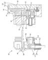
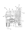
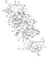
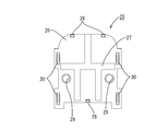
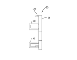
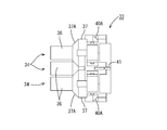
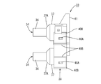
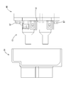
- Diagram showing schematic configuration of equipment Exploded perspective view showing shield case, device side connector and holder Front view showing the first housing Side view showing the first housing Front view showing the second housing Plan view showing the second housing Side view showing the second housing Side view explaining attachment of device side connector to holder Side view showing the device side connector attached to the holder Longitudinal sectional view showing the device side connector attached to the holder Side view showing the shield case attached to the device-side connector on the holder
- a device-side connector 10 (an example of a “connector” of the present invention) of this embodiment is a connector provided in an inverter device of a vehicle such as a hybrid vehicle or an electric vehicle, and as shown in FIG. 1, a motor (generator).
- the electric wire side connector 50 (an example of the “mating side connector” of the present invention) attached to the end of the electric wire 51 that is connected to is fitted and mounted.
- the vertical direction will be described with reference to FIG. 2 and the connector fitting direction in FIG. 2 as the front.
- the electric wire side connector 50 is attached to the terminal of the electric wire 51 connected to the motor (generator) etc. of the vehicle, and is connected to the terminal of the three electric wires 51 capable of transmitting three-phase alternating current as shown in FIG.
- Three terminal fittings 52, an electric wire side housing 53 that holds the terminal fittings 52, and a shield portion 57 that covers the electric wire side housing 53 are configured.
- the terminal fitting 52 is connected to a conductor portion exposed at the end of the electric wire 51.
- the electric wire side housing 53 includes a resin molded portion 54 that covers a connection portion between the electric wire 51 and the terminal fitting 52 and a spacer 55 that holds the three electric wires 51.
- the resin mold part 54 has a cylindrical fitting part in which the distal end side of the terminal fitting 52 protrudes inside.
- a rubber ring 56 for sealing is attached around the cylindrical fitting portion.
- the shield part 57 includes a shield shell 58 that shields the upper side and a shield bracket 59 that shields the lower side.
- the shield shell 58 is provided with an insertion tube portion 16 through which a bolt 60 for holding the fitting state of the connectors 10 and 50 is inserted.
- the shield bracket 59 has a plate-like shield portion that covers the front side of the housing 24 and a cylindrical shield portion that covers the spacer 55, and the plate-like shield portion is fixed to the shield shell 58 by screwing.
- the device-side connector 10 is attached to a shield case 14 (an example of a “case” of the configuration of the present invention) of a device 11 such as an inverter device, and extends from the inside of the shield case 14 to the outside.
- a shield case 14 an example of a “case” of the configuration of the present invention
- the device 11 includes a base member 12 made of a metal plate material, an internal device 13 such as a circuit body fixed to the upper surface of the base member 12, and a shield case 14 fixed to the base member 12.
- the internal device 13 is fixed to the base member 12 by a fixing means 17A such as a bolt, and a holder 46 that holds the device-side connector 10 is fixed to the upper portion of the internal device 13.
- the shield case 14 is made of metal such as aluminum or aluminum alloy, and is fixed to the base member 12 by fixing means 17B such as bolts, and the box-shaped plate-like portion 15 and the device-side connector 10 are connected to each other. It has three cylinder parts 16 for connecting with the outside.
- the plate-like portion 15 is bent so as to cover the internal device 13. As shown in FIG. 1, each cylindrical portion 16 protrudes from the plate-like portion 15 into a cylindrical shape.
- a circular through hole 18 through which the bolt 60 is inserted is formed through the central portion where the three cylindrical portions 16 are integrally connected.
- a cylindrical housing portion 36 of the housing 24 described later is disposed inside the cylindrical portion 16.
- the shield case 14 is shown only for a predetermined width including the cylindrical portion 16, and other portions (other portions including a portion fixed to the base member 12) are omitted (other portions). It is shown in a cut-out form).
- the device-side connector 10 includes a conductive connection member 20 and a housing 24 that holds the connection member 20.
- the connection member 20 is provided at three locations, two at the top of the housing 24 and one at the bottom, both of which are a first terminal 21 extending in the vertical direction and a first terminal on one end side.
- a flexible conductive member 23 connected to 21 and a second terminal 22 connected to the other end of the flexible conductive member 23 and extending in the front-rear direction.
- the second terminal 22 is connected to the first terminal 21 via the flexible conductive member 23.
- the first terminal 21 is a plate-like member, and an upper end side thereof is a terminal fixing portion.
- the terminal fixing portion has a circular terminal fixing hole 21A penetrating therethrough and is more than the terminal fixing hole 21A.
- a rectangular locking hole 21 ⁇ / b> B penetrates at a position aligned on the base end side.
- the base end side of the first terminal 21 (base end side of the terminal fixing portion) is a connection portion to which the flexible conductive member 23 is connected.
- the flexible conductive member 23 is a flexible conductor, and for example, a braided wire in which fine metal wires are knitted in a mesh shape, an electric wire 51, and various flexible members such as copper foil are used. Can do.
- the flexible conductive member 23 is in a state in which the flexible conductive member 23 is overlapped with the terminals 21 and 22 by various known connection means such as brazing (brazing or soldering) or welding. Connected.
- the second terminal 22 has a shape that is long in the front-rear direction, and has a cylindrical terminal connection portion 22A and a plate-like connection portion 22B that extends behind the terminal connection portion 22A and is connected to the flexible conductive member 23. It consists of.
- the housing 24 is made of synthetic resin, and is disposed on the rear side with the first housing 25 and holds the second terminal 22 and has a predetermined clearance CL with respect to the first housing 25. And a second housing 33 that can be engaged.
- the position of the first housing 25 is fixed with respect to the base member 12 through a holder 46 and the like.
- the first housing 25 has a plate-like terminal holding wall 26 that holds the first terminal 21, and left and right sides of the terminal holding wall 26.
- An engagement frame 30 (an example of an “engagement recess” that is a configuration of the present invention) that protrudes forward from the end portion is provided.
- the terminal holding wall 26 is provided so as to penetrate the groove 27 that extends in the vertical direction and the horizontal direction on the front surface side, the locking projection 28 that is locked to the locking hole 21 ⁇ / b> B of the first terminal 21, and the terminal holding wall 26. Fixing holes 29 to be formed.
- the locking projection 28 protrudes in a rectangular shape corresponding to the shape of the locking hole 21B.
- the fixing hole 29 has a circular shape that can be inserted through the shaft portion of the bolt BT.
- the engagement frame 30 is fixed to the terminal holding wall 26 by engaging both ends of the U-shaped frame protruding in a claw shape with the inner wall of the mounting recess 31 provided in the terminal holding wall 26.
- the second housing 33 has three terminal accommodating chambers 34 provided corresponding to the connecting members 20, and the three terminal accommodating chambers 34 are integrated in the rear. As shown in FIG. 13, each terminal accommodating chamber 34 has a terminal accommodating hole 35 therein, and the diameter of the cylindrical accommodating portion 36 provided on the front side and the rear of the cylindrical accommodating portion 36 is increased. An enlarged diameter portion 37 and an integrated wall portion 38 in which the three enlarged diameter portions 37 are integrated behind the enlarged diameter portion 37 are provided.
- the cylindrical housing portion 36 has a cylindrical shape into which the cylindrical terminal connection portion 22A can be inserted, and a distal end portion thereof is provided with a terminal insertion hole 36A into which a mating terminal can be inserted.
- the enlarged diameter portion 37 has a tapered surface 37A that is continuous with the rear end of the cylindrical housing portion 36 and has an outer peripheral surface that is inclined at a uniform angle over the entire circumference. The diameter of the enlarged diameter portion 37 is behind the tapered surface 37A. Is constant.
- insertion recesses 39 through which the bolts BT can be inserted are formed on both side portions of the integral wall portion 38 as shown in FIG. 5.
- 40A of engaging convex parts which protrude in the width direction are each formed in the upper and lower sides of the insertion recessed part 39 among the side surfaces of the integral wall part 38.
- the shape of the engaging convex portion 40A is a triangular shape in which the front end rises vertically from the side surface, and the protruding dimension decreases in a uniform inclination from there to the rear.
- a pair of guide walls 40B is provided above and below the engaging convex portion 40A.
- the engagement convex portion 40 ⁇ / b> A can be engaged with the engagement frame 30 with a predetermined clearance CL.
- the position of the second housing 33 having the engaging convex portion 40A is not fixed with respect to the first housing 25 having the engaging frame 30, and can move within the range of the clearance CL. That is, the second housing 33 can be engaged with the first housing 25 with a predetermined clearance CL.
- a recessed wall 41 that is recessed into the groove portion 27 of the first housing 25 extends in the vertical direction and the left-right direction corresponding to the position of the groove portion 27.
- a boss portion 42 in which a screw hole for bolting by a bolt 60 inserted into the electric wire side connector 50 is formed is formed in the central portion of the front surface of the integral wall portion 38.
- a retainer mounting hole 44 in which a retainer 43 can be mounted is provided on the outer surface of the terminal housing chamber 34 extending from the enlarged diameter portion 37 to the integral wall portion 38 so as to communicate with the terminal housing hole 35.
- the retainer 43 is locked to the rear end of the second terminal 22 to hold the second terminal 22 in the normal position, and a retainer 43 is formed on the side surface of the second housing 33 as shown in FIG. And a pair of mounting frames that are locked to the retaining protrusions 33A and are prevented from coming off.
- the housing 24 (first housing 25) is configured such that the back side thereof is fixed by a holder 46.
- the holder 46 includes a plate-like base 47 and a terminal block 48 that protrudes from the base 47.
- the base 47 is formed with a circular fixing hole 47A having a thread groove formed on the inner peripheral surface thereof.
- a circular terminal fixing hole 48 ⁇ / b> A is formed on the upper surface of the terminal block 48.
- a screw groove is formed on the inner peripheral surface of the terminal fixing hole 48A.
- the holder 46 is fixed on the internal device 13 fixed on the base member 12 of the device 11 by a fixing means such as a bolt by an attaching means (not shown). The position of the first housing 25 thus fixed is fixed with respect to the base member 12.
- the holder 46 is attached and fixed to the internal device 13 fixed on the base member 12 by attachment means (not shown).
- the first terminal 21 is placed on the terminal holding wall 26 of the first housing 25 such that the locking projection 28 of the first housing 25 is locked in the locking hole 21 ⁇ / b> B of the first terminal 21 of the connecting member 20. Deploy.
- the second terminal 22 is accommodated in the cylindrical accommodating portion 36 of the second housing 33, the recessed wall 41 is fitted into the groove portion 27, and the engagement frame 30 is engaged with the engagement convex portion 40A.
- the first housing 25 and the second housing 33 are assembled into a housing 24. Thereby, the apparatus side connector 10 is shape
- the second housing 33 is engaged with the first housing 25 in the range of the predetermined clearance CL in the vertical direction and the front-rear direction. Misalignment is allowed.
- the first housing 25 is fixed to the holder 46 through the shaft portion of the bolt BT in the fixing hole 29 of the first housing 25 and the fixing hole 47A of the holder 46, and the terminal fixing hole 21A of the first terminal 21 is a terminal. Since it is aligned with the position of the fixing hole 48A, it is bolted to the holder 46 with a bolt BT so as to pass through them. (FIG. 12).
- the shield case 14 is put on the device-side connector 10 so that the cylindrical portion 16 of the shield case 14 is inserted into the cylindrical accommodating portion 36 of the second housing 33. At this time, even if the positions of the second housing 33 and the shield case 14 are displaced due to an error in dimensional accuracy or the like, the rear end of the cylindrical portion 16 abuts against the tapered surface 37A and the second housing 33 (the cylindrical housing of the second housing 33). Since the portion 36) is displaced so as to match the position of the shield case 14 (the cylindrical portion 16 thereof), the shield case 14 can be covered (in the normal position). Then, the shield case 14 is fixed to the base member 12 by fixing means 17B such as bolts.
- the device-side connector 10 (connector) is attached to the shield case 14 and attached to the shield case 14 of the device 11 having the base member 12 and the shield case 14 (case) fixed to the base member 12. It is a connector connected to a mating connector, and is fixed to the first terminal 21, a first housing 25 whose position is fixed to the base member 12 and holding the first terminal 21, and the first terminal 21.
- a second terminal 22 connected via the conductive member 23, and a second housing 33 that holds the second terminal 22 and can be engaged with the first housing 25 with a predetermined clearance CL. .
- the shield case 14 and the connector are both fixed to the base member 12, there is a concern that when the shield case 14 is attached to the connector, there is a problem in assembling due to an error in dimensional accuracy or the like. is there.
- the shield case 14 and the first housing 25 are both fixed to the base member 12, but the second housing 33 has a predetermined clearance with respect to the first housing 25. It has CL and can be engaged. Therefore, even when a dimensional accuracy error or the like occurs between the shield case 14 and the connector when the shield case 14 is mounted, the second housing 33 is within the clearance CL with respect to the first housing 25.
- the second terminal 22 held by the second housing 33 is connected to the first terminal 21 held by the first housing 25 via the flexible conductive member 23, the second housing 33. Even when the position of the second terminal 22 is displaced with respect to the first housing 25, the second terminal 22 can be made to follow the displacement of the second housing 33, and the electric wire side connector 50 generated by the position of the second terminal 22. It is also possible to prevent inconveniences and the like during the fitting.
- the predetermined clearance CL is an engagement frame 30 (engagement recess) provided in one of the first housing 25 and the second housing 33 and an engagement provided in the other of the first housing 25 and the second housing 33. Since it arises by engagement with the convex part 40A, the second housing 33 can be engaged with the first housing 25 with a predetermined clearance CL with a simple configuration.
- the second housing 33 Since the second housing 33 is formed with a tapered surface 37A that can come into contact with the shield case 14 when the shield case 14 is attached, the position of the shield case 14 is determined when the shield case 14 is attached. Even if it is displaced with respect to the second housing 33, the second housing 33 can be shifted to a position where the shield case 14 can be mounted when the shield case 14 abuts against the tapered surface 37A.
- the connector of this invention was set as the apparatus side connector 10 provided in the apparatuses 11, such as an inverter apparatus of a vehicle, it is not restricted to this.
- it may be a connector provided in other equipment such as a motor other than the inverter device, and the present invention can also be applied to a connector provided in equipment other than the vehicle.
- Various members can be applied to the base member to which the connector and the case are fixed, depending on the type of equipment.
- the shield case 14 is used, but the present invention can also be applied to a case that does not have a shield function depending on the type of equipment.
- the engagement frame 30 is engaged with the engagement protrusion 40A.
- the present invention is not limited to this, and the first housing 25 and the second housing 33 have a predetermined clearance. If engaged, for example, instead of the engagement frame 30, an engagement recess provided in one housing may engage with an engagement protrusion 40 ⁇ / b> A provided in the other housing. Good.
- Device side connector (connector) 11 ... Equipment 12 ... Base member 13 ... Internal equipment 14 ... Shield case (case) 16 ... Cylinder 17 ... Fixing means 20 ... Connecting member 21 ... First terminal 21A ... Terminal fixing hole 21B ... Locking hole 22 ... Second terminal 23 ... Flexible conductive member 24 ... housing 25 ... first housing 28 ... locking projection 29 ... fixing hole 30 ... engaging frame (engaging recess) 33 ... second housing 34 ... terminal accommodating chamber 36 ... cylindrical accommodating portion 37 ... expanded diameter portion 37A ... tapered surface 40A ... engagement convex portion 40B ... guide wall 46 ... holder 47A ... fixing hole 48A ... terminal fixing hole 50 ... wire side connector 51 ... wire BT ... bolt CL ... clearance
Landscapes
- Details Of Connecting Devices For Male And Female Coupling (AREA)
- Connector Housings Or Holding Contact Members (AREA)
- Coupling Device And Connection With Printed Circuit (AREA)
Abstract
Description
(2)前記所定のクリアランスは、前記第1ハウジング及び前記第2ハウジングの一方に設けられる係合凹部と、前記第1ハウジング及び前記第2ハウジングの他方に設けられる係合凸部との係合により生じる。
このようにすれば、簡易な構成で第2ハウジングを第1ハウジングに対して所定のクリアランスを有して係合させることができる。
このようにすれば、ケース装着の際に、ケースの位置がコネクタに対してずれていても、ケースがテーパ面に当接した際に、第2ハウジングをケースが装着可能な位置にずらすことが可能になる。
以下、本発明を具現化した実施形態1のコネクタについて、図1~図14を参照して説明する。
本実施形態の機器側コネクタ10(本発明の「コネクタ」の一例)は、ハイブリッド自動車や電気自動車等の車両のインバータ装置に設けられるコネクタであって、図1に示すように、モータ(ジェネレータ)に連なる電線51の端末に取付られた電線側コネクタ50(本発明の「相手側コネクタ」の一例)が嵌合装着されるものである。以下では、上下方向については、図2を基準とし、図2におけるコネクタ嵌合方向を前方として説明する。
電線側ハウジング53は、電線51と端子金具52との接続部分を覆う樹脂モールド部54と、3本の電線51を保持するスペーサ55とからなる。
樹脂モールド部54は、端子金具52の先端側が内部に突出する筒状嵌合部を有する。筒状嵌合部の周囲には、シール用のゴムリング56が装着されている。
シールドシェル58には、両コネクタ10,50の嵌合状態を保持するためのボルト60が挿通される挿通筒部16が設けられている。
機器11は、金属板材からなるベース部材12と、ベース部材12の上面に固定される回路体等の内部機器13と、ベース部材12に固定されるシールドケース14とを備えて構成される。
各筒部16は、図1に示すように、板状部15から円筒形状に突出している。
接続部材20は、図5に示すように、ハウジング24の上部に2箇所、下部に1箇所の3箇所に設けられており、共に、上下方向に延びる第1端子21と、一端側が第1端子21に接続された可撓性導電部材23と、可撓性導電部材23の他端側に接続され前後方向に延びる第2端子22とを備えている。これにより、第2端子22は、第1端子21に可撓性導電部材23を介して接続されている。
第1端子21の基端側(端子固定部の基端側)は、可撓性導電部材23が接続される接続部とされている。
固定孔29は、ボルトBTの軸部を挿通可能な円形状をなす。
係合枠30は、コ字状の枠体の爪状に突出する両端を端子保持壁26に凹設された装着凹部31の内壁に係止させることにより端子保持壁26に固定されている。
各端子収容室34は、図13に示すように、内部に端子収容孔35を有しており、前方側に設けられた筒状収容部36と、筒状収容部36の後方において拡径する拡径部37と、拡径部37の後方において3つの拡径部37が一体となった一体壁部38とを備えている。
拡径部37は、筒状収容部36の後端に連なり全周に亘って一様な角度で外周面が傾斜するテーパ面37Aを有し、テーパ面37Aの後方で拡径部37の径が一定となっている。
一体壁部38の側面のうち、挿通凹部39の上下には、幅方向に突出する係合凸部40Aがそれぞれ形成されている。
即ち、第2ハウジング33は、第1ハウジング25に対して所定のクリアランスCLを有して係合可能となっている。
一体壁部38の前面の中心部には、図13に示すように、電線側コネクタ50に挿通したボルト60によるボルト締めのためのネジ孔の形成されたボス部42が形成されている。
ハウジング24(第1ハウジング25)は、その背面側がホルダ46により固定されるようになっている。
基部47には、内周面にネジ溝が形成された円形状の固定孔47Aが貫通形成されている。
端子台部48の上面には、円形状の端子固定孔48Aが形成されている。端子固定孔48Aの内周面には、ネジ溝が形成されている。
ホルダ46をベース部材12上に固定された内部機器13に対して図示しない取付手段により取り付けて固定する。
(1)機器側コネクタ10(コネクタ)は、ベース部材12とこのベース部材12に固定されたシールドケース14(ケース)とを有する機器11のシールドケース14に装着されてシールドケース14に装着されて相手側コネクタに接続されるコネクタであって、第1端子21と、ベース部材12に対して位置が固定されるとともに第1端子21を保持する第1ハウジング25と、第1端子21に可撓性導電部材23を介して接続される第2端子22と、第2端子22を保持し、第1ハウジング25に対して所定のクリアランスCLを有して係合可能な第2ハウジング33とを備える。
本発明は上記記述及び図面によって説明した実施形態に限定されるものではなく、例えば次のような実施形態も本発明の技術的範囲に含まれる。
(1)上記実施形態では、本発明のコネクタは、車両のインバータ装置等の機器11に設けられる機器側コネクタ10としたが、これに限られない。例えば、インバータ装置以外のモータ等の他の機器に設けられるコネクタであってもよく、また、車両以外の機器に設けられるコネクタに本発明を適用することも可能である。また、機器の種類に応じて、コネクタ及びケースが固定されるベース部材についても、種々の部材が適用可能である。
(3)上記実施形態では、係合枠30が係合凸部40Aに係合する構成としたが、これに限られず、第1ハウジング25と第2ハウジング33とが所定のクリアランスを有して係合するのであれば、例えば、係合枠30に代えて一方のハウジングに凹設された係合凹部が他方のハウジングに凸設された係合凸部40Aに係合するものであってもよい。
11...機器
12...ベース部材
13...内部機器
14...シールドケース(ケース)
16...筒部
17...固定手段
20...接続部材
21...第1端子
21A...端子固定孔
21B...係止孔
22...第2端子
23...可撓性導電部材
24...ハウジング
25...第1ハウジング
28...係止突部
29...固定孔
30...係合枠(係合凹部)
33...第2ハウジング
34...端子収容室
36...筒状収容部
37...拡径部
37A...テーパ面
40A...係合凸部
40B...ガイド壁
46...ホルダ
47A...固定孔
48A...端子固定孔
50...電線側コネクタ
51...電線
BT...ボルト
CL...クリアランス
Claims (4)
- ベース部材とこのベース部材に固定されたケースとを有する機器の前記ケースに装着されて相手側コネクタに接続されるコネクタであって、
第1端子と、
前記ベース部材に対して位置が固定されるとともに前記第1端子を保持する第1ハウジングと、
前記第1端子に可撓性導電部材を介して接続される第2端子と、
前記第2端子を保持し、前記第1ハウジングに対して所定のクリアランスを有して係合可能な第2ハウジングと、を備えるコネクタ。 - 前記所定のクリアランスは、前記第1ハウジング及び前記第2ハウジングの一方に設けられる係合凹部と、前記第1ハウジング及び前記第2ハウジングの他方に設けられる係合凸部との係合により生じることを特徴とする請求項1記載のコネクタ。
- 前記第2ハウジングには、前記ケースの装着の際に前記ケースに当接可能なテーパ面が形成されていることを特徴とする請求項1又は請求項2記載のコネクタ。
- 前記第1端子は、前記ベース部材に対して位置が固定されたホルダに固定されていることを特徴とする請求項1ないし請求項3のいずれか一項に記載のコネクタ。
Priority Applications (3)
| Application Number | Priority Date | Filing Date | Title |
|---|---|---|---|
| DE112012001577.0T DE112012001577B4 (de) | 2011-04-05 | 2012-04-03 | Verbinder |
| US14/006,711 US9105998B2 (en) | 2011-04-05 | 2012-04-03 | Connector |
| CN201280016927.3A CN103460516B (zh) | 2011-04-05 | 2012-04-03 | 连接器 |
Applications Claiming Priority (2)
| Application Number | Priority Date | Filing Date | Title |
|---|---|---|---|
| JP2011-083482 | 2011-04-05 | ||
| JP2011083482A JP5668983B2 (ja) | 2011-04-05 | 2011-04-05 | コネクタ |
Publications (1)
| Publication Number | Publication Date |
|---|---|
| WO2012137766A1 true WO2012137766A1 (ja) | 2012-10-11 |
Family
ID=46969163
Family Applications (1)
| Application Number | Title | Priority Date | Filing Date |
|---|---|---|---|
| PCT/JP2012/059052 Ceased WO2012137766A1 (ja) | 2011-04-05 | 2012-04-03 | コネクタ |
Country Status (5)
| Country | Link |
|---|---|
| US (1) | US9105998B2 (ja) |
| JP (1) | JP5668983B2 (ja) |
| CN (1) | CN103460516B (ja) |
| DE (1) | DE112012001577B4 (ja) |
| WO (1) | WO2012137766A1 (ja) |
Cited By (1)
| Publication number | Priority date | Publication date | Assignee | Title |
|---|---|---|---|---|
| WO2015087717A1 (ja) * | 2013-12-13 | 2015-06-18 | 株式会社オートネットワーク技術研究所 | コネクタ |
Families Citing this family (7)
| Publication number | Priority date | Publication date | Assignee | Title |
|---|---|---|---|---|
| JP5668983B2 (ja) * | 2011-04-05 | 2015-02-12 | 株式会社オートネットワーク技術研究所 | コネクタ |
| JP6071448B2 (ja) * | 2012-11-13 | 2017-02-01 | 矢崎総業株式会社 | コネクタ |
| DE202012011808U1 (de) * | 2012-12-10 | 2014-03-13 | Rosenberger Hochfrequenztechnik Gmbh & Co. Kg | Verbindungsvorrichtung |
| JP6107376B2 (ja) * | 2013-04-24 | 2017-04-05 | 日立金属株式会社 | コネクタ及びワイヤハーネス |
| JP7055783B2 (ja) * | 2019-10-17 | 2022-04-18 | 矢崎総業株式会社 | 嵌合コネクタ |
| CN114096137A (zh) * | 2021-11-01 | 2022-02-25 | 浙江吉利控股集团有限公司 | 车辆及其电子设备 |
| US12401160B2 (en) * | 2022-03-09 | 2025-08-26 | Tyco Electronics (Shanghai) Co., Ltd. | Connector and connector assembly |
Citations (7)
| Publication number | Priority date | Publication date | Assignee | Title |
|---|---|---|---|---|
| JPS5526594B1 (ja) * | 1971-03-30 | 1980-07-14 | ||
| JPH08279945A (ja) * | 1995-04-07 | 1996-10-22 | Sony Corp | テレビカメラと周辺機器の脱着装置 |
| JPH10228939A (ja) * | 1997-01-08 | 1998-08-25 | Connecteurs Cinch Sa | 雌型電気接点部材 |
| JPH11265740A (ja) * | 1997-12-23 | 1999-09-28 | Connecteurs Cinch Sa | 雌型電気接触部材 |
| JP2000082518A (ja) * | 1998-09-08 | 2000-03-21 | Connecteurs Cinch Sa | 雌型電気接点部材 |
| WO2011016272A1 (ja) * | 2009-08-03 | 2011-02-10 | 矢崎総業株式会社 | コネクタ |
| JP2011034935A (ja) * | 2009-08-06 | 2011-02-17 | Yazaki Corp | コネクタ |
Family Cites Families (20)
| Publication number | Priority date | Publication date | Assignee | Title |
|---|---|---|---|---|
| DE2828822C2 (de) | 1978-06-30 | 1984-04-12 | Siemens AG, 1000 Berlin und 8000 München | Digitale Halbleiterschaltung |
| JP3035541B1 (ja) | 1999-03-19 | 2000-04-24 | エスエムケイ株式会社 | フロ―ティングコネクタ |
| JP4015590B2 (ja) * | 2003-06-04 | 2007-11-28 | 住友電装株式会社 | ケースのシール構造、及びその組付方法 |
| WO2005013435A1 (en) * | 2003-08-01 | 2005-02-10 | Inter Automotive Closures Inc. | Self-adjustable junction connector system |
| JP2007220542A (ja) * | 2006-02-17 | 2007-08-30 | Iriso Denshi Kogyo Kk | コネクタ |
| JP2007250362A (ja) * | 2006-03-16 | 2007-09-27 | Toyota Motor Corp | コネクタ構造およびコネクタ式端子台構造 |
| US7575455B2 (en) * | 2007-05-29 | 2009-08-18 | Siemens Energy, Inc. | Eccentric polygonal main lead flexible connector assembly |
| US7682205B2 (en) * | 2007-11-15 | 2010-03-23 | Tyco Electronics Corporation | Multi position electrical connector assembly |
| JP5185022B2 (ja) * | 2008-08-27 | 2013-04-17 | イリソ電子工業株式会社 | 電気接触子及びこれを用いたコネクタ |
| JP5426202B2 (ja) * | 2009-03-25 | 2014-02-26 | 矢崎総業株式会社 | コネクタ |
| JP2011028853A (ja) * | 2009-07-21 | 2011-02-10 | Sumitomo Wiring Syst Ltd | モールドコネクタ |
| CN101656383B (zh) * | 2009-08-03 | 2012-11-21 | 上海雷迪埃电子有限公司 | 弹簧加载连接器 |
| JP2011249076A (ja) * | 2010-05-25 | 2011-12-08 | Fujitsu Component Ltd | フローティングコネクタ |
| JP5885013B2 (ja) * | 2010-09-22 | 2016-03-15 | 株式会社オートネットワーク技術研究所 | コネクタ |
| WO2012124801A1 (ja) * | 2011-03-17 | 2012-09-20 | 株式会社オートネットワーク技術研究所 | コネクタ |
| JP5668983B2 (ja) * | 2011-04-05 | 2015-02-12 | 株式会社オートネットワーク技術研究所 | コネクタ |
| US8376766B1 (en) * | 2011-08-16 | 2013-02-19 | International Business Machines Corporation | Connector with compliant section |
| JP5751194B2 (ja) * | 2011-09-08 | 2015-07-22 | 日立金属株式会社 | コネクタ及びワイヤハーネス |
| JP2014007133A (ja) * | 2012-05-28 | 2014-01-16 | Auto Network Gijutsu Kenkyusho:Kk | コネクタ |
| JP2014022266A (ja) * | 2012-07-20 | 2014-02-03 | Sumitomo Wiring Syst Ltd | コネクタ |
-
2011
- 2011-04-05 JP JP2011083482A patent/JP5668983B2/ja not_active Expired - Fee Related
-
2012
- 2012-04-03 US US14/006,711 patent/US9105998B2/en not_active Expired - Fee Related
- 2012-04-03 DE DE112012001577.0T patent/DE112012001577B4/de not_active Expired - Fee Related
- 2012-04-03 CN CN201280016927.3A patent/CN103460516B/zh not_active Expired - Fee Related
- 2012-04-03 WO PCT/JP2012/059052 patent/WO2012137766A1/ja not_active Ceased
Patent Citations (7)
| Publication number | Priority date | Publication date | Assignee | Title |
|---|---|---|---|---|
| JPS5526594B1 (ja) * | 1971-03-30 | 1980-07-14 | ||
| JPH08279945A (ja) * | 1995-04-07 | 1996-10-22 | Sony Corp | テレビカメラと周辺機器の脱着装置 |
| JPH10228939A (ja) * | 1997-01-08 | 1998-08-25 | Connecteurs Cinch Sa | 雌型電気接点部材 |
| JPH11265740A (ja) * | 1997-12-23 | 1999-09-28 | Connecteurs Cinch Sa | 雌型電気接触部材 |
| JP2000082518A (ja) * | 1998-09-08 | 2000-03-21 | Connecteurs Cinch Sa | 雌型電気接点部材 |
| WO2011016272A1 (ja) * | 2009-08-03 | 2011-02-10 | 矢崎総業株式会社 | コネクタ |
| JP2011034935A (ja) * | 2009-08-06 | 2011-02-17 | Yazaki Corp | コネクタ |
Cited By (3)
| Publication number | Priority date | Publication date | Assignee | Title |
|---|---|---|---|---|
| WO2015087717A1 (ja) * | 2013-12-13 | 2015-06-18 | 株式会社オートネットワーク技術研究所 | コネクタ |
| JP2015115251A (ja) * | 2013-12-13 | 2015-06-22 | 株式会社オートネットワーク技術研究所 | コネクタ |
| US9698528B2 (en) | 2013-12-13 | 2017-07-04 | Autonetworks Technologies, Ltd. | Connector for directly connecting an inverter and a motor |
Also Published As
| Publication number | Publication date |
|---|---|
| DE112012001577T5 (de) | 2014-02-13 |
| JP5668983B2 (ja) | 2015-02-12 |
| JP2012221614A (ja) | 2012-11-12 |
| CN103460516A (zh) | 2013-12-18 |
| DE112012001577B4 (de) | 2017-10-19 |
| US20140017947A1 (en) | 2014-01-16 |
| CN103460516B (zh) | 2016-05-04 |
| US9105998B2 (en) | 2015-08-11 |
Similar Documents
| Publication | Publication Date | Title |
|---|---|---|
| JP5668983B2 (ja) | コネクタ | |
| CN103579870B (zh) | 连接器 | |
| US9455525B2 (en) | Connector with flexible conductive member to isolate terminal from vibrations in a wire | |
| JP4632320B2 (ja) | 機器用コネクタ | |
| US20140120763A1 (en) | Connector | |
| JP2010250995A (ja) | コネクタ | |
| US9592775B2 (en) | Wiring harness protector fixing structure | |
| WO2011096135A1 (ja) | 防水型シールドコネクタ | |
| JP2014038793A (ja) | コネクタ | |
| JP2013065502A (ja) | 導電板およびジョイントコネクタ | |
| JP5995105B2 (ja) | コネクタ | |
| CN102484334B (zh) | 连接器 | |
| JP5585106B2 (ja) | コネクタ装置 | |
| JP2015005432A (ja) | シールドコネクタ | |
| JP4941741B2 (ja) | コネクタ | |
| JP5840175B2 (ja) | コネクタ、及びコネクタユニット | |
| JP2023172634A (ja) | コネクタ | |
| JP4941740B2 (ja) | コネクタ | |
| JP2007103044A (ja) | シールドコネクタ | |
| CN119698737A (zh) | 连接器 | |
| JP2007258105A (ja) | 電気接続構造 | |
| JP2012169219A (ja) | シールドコネクタ | |
| WO2022196423A1 (ja) | コネクタ | |
| JP2012089297A (ja) | 機器用コネクタ | |
| JP2005310585A (ja) | 機器用コネクタ |
Legal Events
| Date | Code | Title | Description |
|---|---|---|---|
| WWE | Wipo information: entry into national phase |
Ref document number: 201280016927.3 Country of ref document: CN |
|
| 121 | Ep: the epo has been informed by wipo that ep was designated in this application |
Ref document number: 12767274 Country of ref document: EP Kind code of ref document: A1 |
|
| WWE | Wipo information: entry into national phase |
Ref document number: 14006711 Country of ref document: US |
|
| WWE | Wipo information: entry into national phase |
Ref document number: 1120120015770 Country of ref document: DE Ref document number: 112012001577 Country of ref document: DE |
|
| 122 | Ep: pct application non-entry in european phase |
Ref document number: 12767274 Country of ref document: EP Kind code of ref document: A1 |