WO2012099178A1 - 非水電解質電池 - Google Patents
非水電解質電池 Download PDFInfo
- Publication number
- WO2012099178A1 WO2012099178A1 PCT/JP2012/050987 JP2012050987W WO2012099178A1 WO 2012099178 A1 WO2012099178 A1 WO 2012099178A1 JP 2012050987 W JP2012050987 W JP 2012050987W WO 2012099178 A1 WO2012099178 A1 WO 2012099178A1
- Authority
- WO
- WIPO (PCT)
- Prior art keywords
- negative electrode
- electrode layer
- solid electrolyte
- active material
- powder
- Prior art date
- Legal status (The legal status is an assumption and is not a legal conclusion. Google has not performed a legal analysis and makes no representation as to the accuracy of the status listed.)
- Ceased
Links
Classifications
-
- H—ELECTRICITY
- H01—ELECTRIC ELEMENTS
- H01M—PROCESSES OR MEANS, e.g. BATTERIES, FOR THE DIRECT CONVERSION OF CHEMICAL ENERGY INTO ELECTRICAL ENERGY
- H01M10/00—Secondary cells; Manufacture thereof
- H01M10/05—Accumulators with non-aqueous electrolyte
- H01M10/058—Construction or manufacture
-
- H—ELECTRICITY
- H01—ELECTRIC ELEMENTS
- H01M—PROCESSES OR MEANS, e.g. BATTERIES, FOR THE DIRECT CONVERSION OF CHEMICAL ENERGY INTO ELECTRICAL ENERGY
- H01M10/00—Secondary cells; Manufacture thereof
- H01M10/05—Accumulators with non-aqueous electrolyte
- H01M10/056—Accumulators with non-aqueous electrolyte characterised by the materials used as electrolytes, e.g. mixed inorganic/organic electrolytes
- H01M10/0561—Accumulators with non-aqueous electrolyte characterised by the materials used as electrolytes, e.g. mixed inorganic/organic electrolytes the electrolyte being constituted of inorganic materials only
- H01M10/0562—Solid materials
-
- H—ELECTRICITY
- H01—ELECTRIC ELEMENTS
- H01M—PROCESSES OR MEANS, e.g. BATTERIES, FOR THE DIRECT CONVERSION OF CHEMICAL ENERGY INTO ELECTRICAL ENERGY
- H01M4/00—Electrodes
- H01M4/02—Electrodes composed of, or comprising, active material
- H01M4/13—Electrodes for accumulators with non-aqueous electrolyte, e.g. for lithium-accumulators; Processes of manufacture thereof
- H01M4/131—Electrodes based on mixed oxides or hydroxides, or on mixtures of oxides or hydroxides, e.g. LiCoOx
-
- H—ELECTRICITY
- H01—ELECTRIC ELEMENTS
- H01M—PROCESSES OR MEANS, e.g. BATTERIES, FOR THE DIRECT CONVERSION OF CHEMICAL ENERGY INTO ELECTRICAL ENERGY
- H01M4/00—Electrodes
- H01M4/02—Electrodes composed of, or comprising, active material
- H01M4/36—Selection of substances as active materials, active masses, active liquids
- H01M4/48—Selection of substances as active materials, active masses, active liquids of inorganic oxides or hydroxides
- H01M4/485—Selection of substances as active materials, active masses, active liquids of inorganic oxides or hydroxides of mixed oxides or hydroxides for inserting or intercalating light metals, e.g. LiTi2O4 or LiTi2OxFy
-
- H—ELECTRICITY
- H01—ELECTRIC ELEMENTS
- H01M—PROCESSES OR MEANS, e.g. BATTERIES, FOR THE DIRECT CONVERSION OF CHEMICAL ENERGY INTO ELECTRICAL ENERGY
- H01M4/00—Electrodes
- H01M4/02—Electrodes composed of, or comprising, active material
- H01M4/36—Selection of substances as active materials, active masses, active liquids
- H01M4/58—Selection of substances as active materials, active masses, active liquids of inorganic compounds other than oxides or hydroxides, e.g. sulfides, selenides, tellurides, halogenides or LiCoFy; of polyanionic structures, e.g. phosphates, silicates or borates
- H01M4/583—Carbonaceous material, e.g. graphite-intercalation compounds or CFx
-
- H—ELECTRICITY
- H01—ELECTRIC ELEMENTS
- H01M—PROCESSES OR MEANS, e.g. BATTERIES, FOR THE DIRECT CONVERSION OF CHEMICAL ENERGY INTO ELECTRICAL ENERGY
- H01M4/00—Electrodes
- H01M4/02—Electrodes composed of, or comprising, active material
- H01M4/62—Selection of inactive substances as ingredients for active masses, e.g. binders, fillers
- H01M4/624—Electric conductive fillers
- H01M4/625—Carbon or graphite
-
- H—ELECTRICITY
- H01—ELECTRIC ELEMENTS
- H01M—PROCESSES OR MEANS, e.g. BATTERIES, FOR THE DIRECT CONVERSION OF CHEMICAL ENERGY INTO ELECTRICAL ENERGY
- H01M2220/00—Batteries for particular applications
- H01M2220/20—Batteries in motive systems, e.g. vehicle, ship, plane
-
- Y—GENERAL TAGGING OF NEW TECHNOLOGICAL DEVELOPMENTS; GENERAL TAGGING OF CROSS-SECTIONAL TECHNOLOGIES SPANNING OVER SEVERAL SECTIONS OF THE IPC; TECHNICAL SUBJECTS COVERED BY FORMER USPC CROSS-REFERENCE ART COLLECTIONS [XRACs] AND DIGESTS
- Y02—TECHNOLOGIES OR APPLICATIONS FOR MITIGATION OR ADAPTATION AGAINST CLIMATE CHANGE
- Y02E—REDUCTION OF GREENHOUSE GAS [GHG] EMISSIONS, RELATED TO ENERGY GENERATION, TRANSMISSION OR DISTRIBUTION
- Y02E60/00—Enabling technologies; Technologies with a potential or indirect contribution to GHG emissions mitigation
- Y02E60/10—Energy storage using batteries
-
- Y—GENERAL TAGGING OF NEW TECHNOLOGICAL DEVELOPMENTS; GENERAL TAGGING OF CROSS-SECTIONAL TECHNOLOGIES SPANNING OVER SEVERAL SECTIONS OF THE IPC; TECHNICAL SUBJECTS COVERED BY FORMER USPC CROSS-REFERENCE ART COLLECTIONS [XRACs] AND DIGESTS
- Y02—TECHNOLOGIES OR APPLICATIONS FOR MITIGATION OR ADAPTATION AGAINST CLIMATE CHANGE
- Y02P—CLIMATE CHANGE MITIGATION TECHNOLOGIES IN THE PRODUCTION OR PROCESSING OF GOODS
- Y02P70/00—Climate change mitigation technologies in the production process for final industrial or consumer products
- Y02P70/50—Manufacturing or production processes characterised by the final manufactured product
Definitions
- the present invention relates to a non-aqueous electrolyte battery having a positive electrode layer, a negative electrode layer, and a solid electrolyte layer interposed between these layers.
- Non-aqueous electrolyte batteries have a long life, high efficiency, and high capacity, and are used in mobile devices such as mobile phones, notebook computers, and digital cameras.
- Typical examples of the nonaqueous electrolyte battery include a lithium battery and a lithium ion secondary battery (hereinafter simply referred to as “lithium battery”) using a lithium ion transfer reaction between positive and negative electrode layers.
- This lithium battery has a positive electrode layer containing a positive electrode active material, a negative electrode layer containing a negative electrode active material, and an electrolyte layer interposed between these two layers. And it is a secondary battery of the system which charges / discharges, when lithium (Li) ion moves through an electrolyte layer between a positive electrode layer and a negative electrode layer.
- all solid-state batteries using inorganic solid electrolytes instead of organic electrolytes have been proposed (see, for example, Patent Documents 1 to 3).
- Patent Document 1 discloses that a predetermined mold is filled with a powdered positive electrode active material, a powdered electrolyte material, and a powdered negative electrode active material, and pressed. Are listed.
- Patent Documents 2 and 3 describe that a positive electrode layer, a solid electrolyte layer, and a negative electrode layer are sequentially formed and stacked by a vapor phase method.
- Patent Document 3 discloses, as negative electrode active material, carbon materials such as graphite and hard carbon, silicon (Si), silicon oxide (SiO x (0 ⁇ x ⁇ 2)), tin alloy, lithium cobalt nitride.
- carbon materials such as graphite and hard carbon, silicon (Si), silicon oxide (SiO x (0 ⁇ x ⁇ 2)), tin alloy, lithium cobalt nitride.
- SiCoN silicon
- Li metal lithium alloy
- LiAl lithium alloy
- Patent Document 1 when the positive electrode layer, the solid electrolyte layer, and the negative electrode layer are all formed by molding powder, the positive electrode layer and the negative electrode layer are thick, However, the solid electrolyte layer is also thick, which leads to a decrease in volume output density.
- Patent Documents 2 and 3 in the case of a film-forming type in which the constituent members of the positive electrode layer, the solid electrolyte layer, and the negative electrode layer are all formed by a vapor phase method, the solid electrolyte layer Is thin and it is easy to ensure the volume output density, but the positive electrode layer and the negative electrode layer are also thin, leading to a decrease in capacity.
- the present invention has been made in view of the above circumstances, and one of its purposes is to provide a nonaqueous electrolyte battery that has a high capacity and volumetric output density and can improve charge / discharge cycle characteristics. It is in.
- the inventors of the present invention consider forming a negative electrode layer by molding a powder and simultaneously forming a solid electrolyte layer by vapor deposition to improve both battery capacity and volume output density. It was. Therefore, a positive electrode member in which a molded body of LiCoO 2 powder is used for the positive electrode layer and a solid electrolyte layer is formed thereon by a gas phase method, and a molded body of graphite (graphite) powder is used for the negative electrode layer.
- An all-solid-type nonaqueous electrolyte battery in which both members are laminated and bonded so that the solid electrolyte layers of both members are opposed to each other is prepared and charged. A discharge cycle test was conducted.
- this battery had an internal short circuit at an early stage of the cycle test and had a problem in terms of charge / discharge cycle characteristics.
- the negative electrode layer expands and contracts with charge and discharge, and cracks are generated in the solid electrolyte layer due to the stress, so that Li deposited on the surface of the negative electrode layer with repeated charge and discharge passes through the crack to form a dendritic shape. This is thought to be caused by an internal short circuit that has grown into a positive electrode layer.
- the adhesion between the negative electrode layer and the solid electrolyte layer may decrease due to the expansion and contraction of the negative electrode layer due to charge / discharge. In this case, the Li ion migration resistance at the interface between the two layers increases, and the charge / discharge cycle It is also conceivable that the characteristics are degraded.
- the nonaqueous electrolyte battery of the present invention has a positive electrode layer, a negative electrode layer, and a solid electrolyte layer interposed between these two layers.
- the negative electrode layer contains a negative electrode active material powder and a solid electrolyte powder.
- the negative electrode active material has a volume change rate of 1% or less during charge and discharge and an average particle size of the powder of 8 ⁇ m or less.
- the solid electrolyte layer is formed by a vapor phase method.
- the negative electrode layer is formed by forming a powder, and the solid electrolyte layer is formed by a vapor phase method, thereby making it possible to improve both capacity and volume output density. it can.
- the volume change rate during charging / discharging of the negative electrode active material is 1% or less, so that expansion / contraction of the negative electrode layer accompanying charging / discharging is suppressed, cracks are generated in the solid electrolyte layer, and the negative electrode layer, the solid electrolyte layer, It can suppress that adhesiveness falls.
- the rate of change in volume (%) during charge / discharge refers to the volume (Vc) when Li is occluded during full charge (when it reaches the end-of-charge voltage) and when fully discharged (when reached at the end-of-discharge voltage).
- the value ([Vc ⁇ Vd] / Vd), expressed as a percentage, is obtained by dividing the volume change by subtracting the volume (Vd) at the time of releasing Li from the volume (Vd) when releasing Li at the time of complete discharge. It is a thing. Therefore, an internal short circuit hardly occurs and the charge / discharge cycle characteristics can be improved.
- the negative electrode layer contains the negative electrode active material powder and the solid electrolyte powder
- the negative electrode layer has a structure in which the solid electrolyte exists around the negative electrode active material particles.
- the absolute volume change amount increases as the particle diameter increases. Therefore, when the average particle size of the negative electrode active material powder is 8 ⁇ m or less, the absolute volume change amount of the negative electrode active material particles is reduced, so that the expansion and contraction of the negative electrode layer accompanying charge / discharge is effectively reduced.
- the average particle diameter of the negative electrode active material powder is 8 ⁇ m or less, the surface roughness of the negative electrode layer after molding is reduced, so a solid electrolyte layer or the like is formed on the negative electrode layer by a vapor phase method ( Easy to form).
- the average particle diameter of the negative electrode active material powder is preferably, for example, 1 ⁇ m or less from the viewpoint of reducing the volume change of the particles and the surface roughness of the negative electrode layer.
- the average particle size of the powder also changes strictly between charging and discharging. Since the volume change rate of the negative electrode active material is 1% or less, the average particle diameter of the powder hardly changes.
- the average particle diameter of the negative electrode active material powder contained in the negative electrode layer is substantially the same as the average particle diameter of the material powder before molding, and the measurement of the particle size is performed when the negative electrode active material releases Li. (That is, in a discharged state).
- the average particle diameter is an average particle diameter (arithmetic average value of diameters of particles photographed by optical microscopy or transmission electron microscopy) defined in JIS Z 8901: 2006.
- the thickness of the negative electrode layer is preferably 30 ⁇ m or more, and more preferably 60 ⁇ m or more, from the viewpoint of securing capacity.
- the thickness of the solid electrolyte layer is preferably, for example, 30 ⁇ m or less, and more preferably 10 ⁇ m or less, from the viewpoint of securing volume output density.
- the solid electrolyte layer is formed by a vapor phase method, it is easy to form the solid electrolyte layer as thin as compared with the case of forming a powder. Further, by forming the solid electrolyte layer by a vapor phase method, the solid electrolyte layer is denser than when powder is formed, and an internal short circuit due to Li dendrite growth is less likely to occur.
- vapor phase method examples include physical vapor deposition (PVD) methods such as vacuum vapor deposition, pulsed laser deposition (PLD), laser ablation, ion plating, and sputtering.
- PVD physical vapor deposition
- PLD pulsed laser deposition
- the conditions of the vapor phase method are not particularly limited, but a dense film can be formed as the impurity concentration in the atmosphere in the film formation chamber at the time of film formation is lowered. It is preferable to set it to Pa or less.
- Li ions are exchanged at the interface between the negative electrode layer and the solid electrolyte layer.
- the negative electrode layer is composed only of the powder of the negative electrode active material, ions are smoothly exchanged at the negative electrode layer interface, but ions are not sufficiently diffused inside the negative electrode layer (part away from the interface), and the negative electrode
- the negative electrode active material powder inside the layer is not effectively used for the battery reaction. This problem tends to appear more prominently as the thickness of the negative electrode layer becomes thicker (for example, 20 ⁇ m or more).
- the negative electrode layer contains the powder of the negative electrode active material and the solid electrolyte powder, and the negative electrode active material powder and the solid electrolyte powder are mixed in the negative electrode layer, so that ion diffusion inside the negative electrode layer is reduced to the solid electrolyte powder.
- the negative electrode active material powder inside the negative electrode layer can be effectively used for the battery reaction. As a result, the internal resistance can be reduced.
- the negative electrode active material can be mentioned that Li is 4 Ti 5 O 12 or non-graphitizable carbon (hard carbon).
- Li 4 Ti 5 O 12 or hard carbon (non-graphitizable carbon) is suitable because it has a volume change rate of 1% or less during charging and discharging.
- a negative electrode active material when Li is occluded during charging, Li ions enter between crystal lattices, and when Li is released during discharge, Li ions are desorbed from between crystal lattices.
- the volume change rate during charging and discharging is small.
- the volume change rate at the time of charging / discharging is small as compared with graphite which has been frequently used conventionally.
- graphite has a volume change rate of about 10% during charging and discharging.
- Li metal or Li alloy is used as the negative electrode active material, Li is deposited on the surface of the negative electrode layer, and it tends to grow in a dendrite shape.
- the solid electrolyte contained in the negative electrode layer is a sulfide solid electrolyte.
- Typical solid electrolytes include sulfide-based solid electrolytes containing Li 2 S and oxide-based solid electrolytes such as Li 3 PO 4 and LiPON.
- the sulfide-based solid electrolyte include Li 2 S-P 2 S 5 system, Li 2 S-SiS 2 system, Li 2 S-B 2 S 3 system, and further P 2 O 5 and Li 3 PO 4 may be added.
- a sulfide-based solid electrolyte is preferable because it generally exhibits higher lithium ion conductivity than an oxide-based solid electrolyte.
- Li 2 S—P 2 S 5 -based solid electrolytes are more preferable because they exhibit high lithium ion conductivity.
- the negative electrode layer may contain a conductive additive and a binder (binder) as necessary, in addition to the negative electrode active material powder and the solid electrolyte powder.
- a conductive additive such as acetylene black (AB) and ketjen black (KB).
- the binder include polytetrafluoroethylene (PTFE) and polyvinylidene fluoride (PVdF).
- the content of the powder of the negative electrode active material in the negative electrode layer is 30% by mass or more and 80% by mass or less.
- the ratio of the negative electrode active material to the whole negative electrode layer is small, and there is a possibility that the capacity is reduced.
- the content of the negative electrode active material powder in the negative electrode layer exceeds 80% by mass, the proportion of solid electrolyte powder and the like is relatively decreased, which may increase internal resistance and decrease binding properties.
- the ratio of the negative electrode active material powder and the solid electrolyte powder in the negative electrode layer include negative electrode active material powder: 30 to 80% by mass and solid electrolyte powder: 20 to 70% by mass.
- the content of the powder of the negative electrode active material in the negative electrode layer is more preferably more than 30% by mass, still more preferably 40% by mass or more, and the upper limit is more preferably less than 80% by mass, further preferably 70% by mass or less. It is.
- the solid electrolyte layer contains a sulfide solid electrolyte.
- a sulfide-based solid electrolyte is preferable because it generally exhibits a higher lithium ion conductivity than an oxide-based one, and among them, a Li 2 S-P 2 S 5- based solid is preferable.
- the electrolyte is more preferable because it exhibits high lithium ion conductivity.
- the positive electrode layer contains a positive electrode active material.
- positive electrode active materials include lithium-containing composites such as LiCoO 2 , LiNiO 2 , LiMn 2 O 4 , LiFePO 4 , LiNi 1/3 Co 1/3 Mn 1/3 O 2 , LiNi 0.8 Co 0.15 Al 0.05 O 2 An oxide is mentioned.
- these positive electrode active materials in particular, LiNi 1/3 Co 1/3 Mn 1/3 O 2 and LiNi 0.8 Co 0.15 Al 0.05 O 2 have a volume change rate of 1% or less during charge / discharge, which is preferable. is there.
- LiCoO 2 that has been widely used in the past has a volume change rate of 2.6% during charging and discharging.
- a positive electrode active material powder having an average particle size of 6 ⁇ m or less.
- an interface layer for reducing the interface resistance between these two layers may be provided between the positive electrode layer and the solid electrolyte layer.
- the oxide and the sulfide may react to increase the interface resistance at the interface between the positive electrode layer and the solid electrolyte layer. Therefore, the interface resistance can be reduced by providing an interface layer that suppresses interdiffusion between both layers in the vicinity of the interface between the positive electrode layer and the solid electrolyte layer and suppresses the reaction.
- the negative electrode layer is formed by mixing a negative electrode active material powder and a solid electrolyte powder and, if necessary, a conductive additive and a binder, and pressing the mixed powder.
- the pressing pressure at the time of pressing is preferably 100 MPa to 600 MPa, and heat treatment may be performed after the pressure forming.
- the heating temperature is preferably 120 ° C. to 250 ° C.
- the positive electrode layer and the interface layer described above can be formed by a vapor phase method, as with the solid electrolyte layer. Further, the positive electrode layer may be formed by a wet method (coating method) such as a sol-gel method, a colloid method, or a casting method, in addition to a formed body obtained by pressing a powder of the positive electrode active material, similarly to the negative electrode layer. . In addition, when making a positive electrode layer into the molded object of positive electrode active material powder, it is preferable to mix a solid electrolyte powder similarly to a negative electrode layer, and you may add a conductive support agent and a binder as needed.
- the ratio of the positive electrode active material powder and the solid electrolyte powder in the positive electrode layer is, for example, positive electrode active material powder: 50 to 90% by mass, solid electrolyte powder: 10 to 50% by mass. Is preferably a sulfide-based solid electrolyte powder.
- the negative electrode layer is formed by forming a powder
- the solid electrolyte layer is formed by a vapor phase method
- the volume change rate during charge / discharge of the negative electrode active material is 1 % Or less, the capacity and volume output density are high, and it is possible to improve the charge / discharge cycle characteristics.
- Example 1 A non-aqueous electrolyte battery (lithium battery) of the present invention was produced and its battery performance was evaluated.
- Li 4 Ti 5 O 12 powder (average particle size 1 ⁇ m) and Li 2 S-P 2 S 5 solid electrolyte powder (average particle size 1 to 5 ⁇ m) were mixed at a mass ratio of 50:50.
- a negative electrode mixture was prepared.
- a SUS316L foil (thickness 10 ⁇ m) serving as a negative electrode current collector was placed in a mold and filled with a negative electrode mixture from above, and then this was pressure-molded at a pressure of 360 MPa to obtain a negative electrode current collector.
- a negative electrode member in which a negative electrode layer (Li 4 Ti 5 O 12 + Li 2 S—P 2 S 5 solid electrolyte molded body) was formed on was prepared.
- the thickness of the negative electrode layer in this negative electrode member was 60 ⁇ m.
- Li 2 S-P 2 S 5 solid electrolyte Li 2 S and P 2 S 5 are ball milled and mixed at a molar ratio of 4: 1 and then heat-treated at 240 ° C for 1 hour in an Ar atmosphere We used what we did.
- LiCoO 2 powder (average particle size 10 ⁇ m) and Li 2 S-P 2 S 5 solid electrolyte powder (average particle size 1 to 5 ⁇ m) are mixed so that the mass ratio is 70:30.
- a mixture was prepared.
- a SUS316L foil (thickness 20 ⁇ m) serving as a positive electrode current collector was placed in a mold, and after filling the positive electrode mixture from above, this was pressure-molded at a pressure of 360 MPa to obtain a positive electrode current collector.
- Li 2 S-P 2 S 5 solid electrolyte Li 2 S and P 2 S 5 are ball milled and mixed at a molar ratio of 4: 1, followed by heat treatment at 240 ° C for 1 hour in an Ar atmosphere We used what we did.
- Li 2 S-P 2 S 5 based solid electrolyte was formed using the PLD method, respectively, and the solid electrolyte layer (thickness 5 ⁇ m) was formed.
- Li 2 S-P 2 S 5 solid electrolyte was formed by mixing Li 2 S and P 2 S 5 in a molar ratio of 4: 1.
- the two members are laminated so that the solid electrolyte layers of the positive electrode member and the negative electrode member face each other, and heated to 190 ° C. while being pressurized to 16 MPa in the laminating direction and held for 130 minutes.
- the battery was fabricated by fusing and joining both members.
- the nonaqueous electrolyte battery produced as described above was incorporated into a charge / discharge test cell, and this was designated as Sample No. 1-1.
- a battery was fabricated in the same manner as Sample No. 1-1 except that the negative electrode member was fabricated by changing the Li 4 Ti 5 O 12 powder to graphite powder (average particle size 5 ⁇ m). This battery was incorporated into a charge / discharge test cell, and this was designated as Sample No. 1-2.
- a battery was fabricated in the same manner as Sample No. 1-1, except that the positive electrode member was fabricated by changing the LiCoO 2 powder to LiNi 0.8 Co 0.15 Al 0.05 O 2 powder (average particle size 6 ⁇ m). This battery was incorporated in a charge / discharge test cell, and this was designated as Sample No. 1-3.
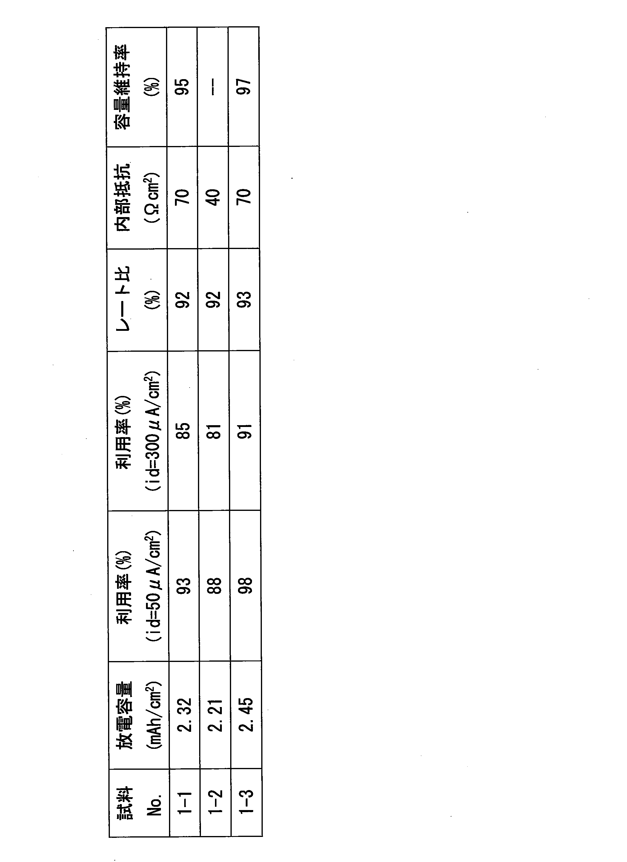
- Table 1 shows the configuration of each battery manufactured. Moreover, the following evaluation was performed about each produced battery. The results are shown in Table 2.
- ⁇ Negative electrode utilization rate> From the initial discharge capacity in the charge / discharge cycle test described above, the utilization factor of the negative electrode when the current density was 50 ⁇ A / cm 2 was examined. Further, the utilization rate of the negative electrode when the current density was 300 ⁇ A / cm 2 was examined from the initial discharge capacity when the current density was a constant current of 300 ⁇ A / cm 2 under the test conditions described above. The utilization factor was obtained by dividing the discharge capacity by the theoretical capacity of the negative electrode. The theoretical capacity of the negative electrode was the product of the theoretical capacity per unit volume of the negative electrode active material and the volume of the negative electrode active material contained in the negative electrode layer. Table 2 shows the negative electrode utilization factor of each battery at each current density (id 50 ⁇ A / cm 2 , 300 ⁇ A / cm 2 ).
- ⁇ Rate ratio> The rate ratio was examined from the initial discharge capacity when the current density was 50 ⁇ A / cm 2 and the initial discharge capacity when the current density was 300 ⁇ A / cm 2 .
- the rate ratio was obtained by dividing the discharge capacity when the current density was 300 ⁇ A / cm 2 by the discharge capacity when the current density was 50 ⁇ A / cm 2 .
- Table 2 shows the rate ratio of each battery.
- the batteries of Sample No. 1-1 and Sample No. 1-3 operated stably for 50 cycles or more without causing an internal short circuit.
- the discharge capacity maintenance ratio at the 50th cycle relative to the initial discharge capacity at the first cycle is 95% for the battery of sample No. 1-1 and 97% for the battery of sample No. 1-3.
- the discharge capacity retention rate at the 50th cycle was as high as 96% or more, and it was found that the battery was excellent in charge / discharge cycle characteristics.
- 1-3 have an initial discharge capacity of 2 mAh / cm 2 or more, and negative electrode utilization rates of 80% or more at current densities of 50 ⁇ A / cm 2 and 300 ⁇ A / cm 2 , respectively.
- the rate ratio was 80% or more, and the internal resistance was less than 100 ⁇ cm 2 .
- the battery of sample No. 1-2 was confirmed to be unable to be charged to 4.2 V in the 24th cycle, and an internal short circuit occurred.
- Example 2 A battery in which the average particle size of the negative electrode active material powder was changed was produced, and the battery performance was evaluated.
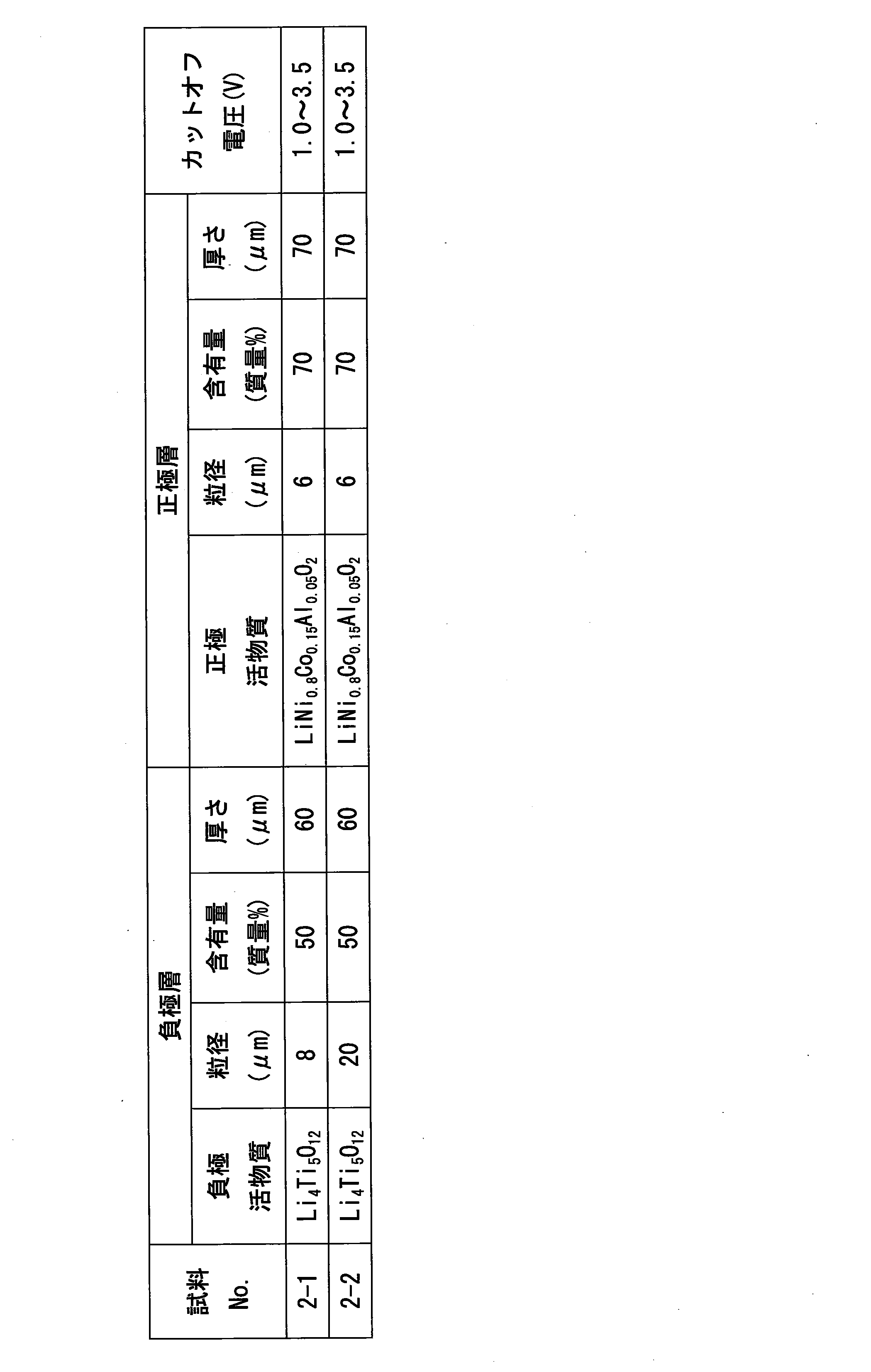
- Batteries were produced in the same manner as in Sample No. 1-3, except that the negative electrode member was produced by changing the average particle size of the Li 4 Ti 5 O 12 powder to 8 ⁇ m and 20 ⁇ m. These batteries were incorporated into a charge / discharge test cell, and these were designated as Sample No. 2-1 and Sample No. 2-2.
- Table 3 shows the configuration of each battery fabricated.
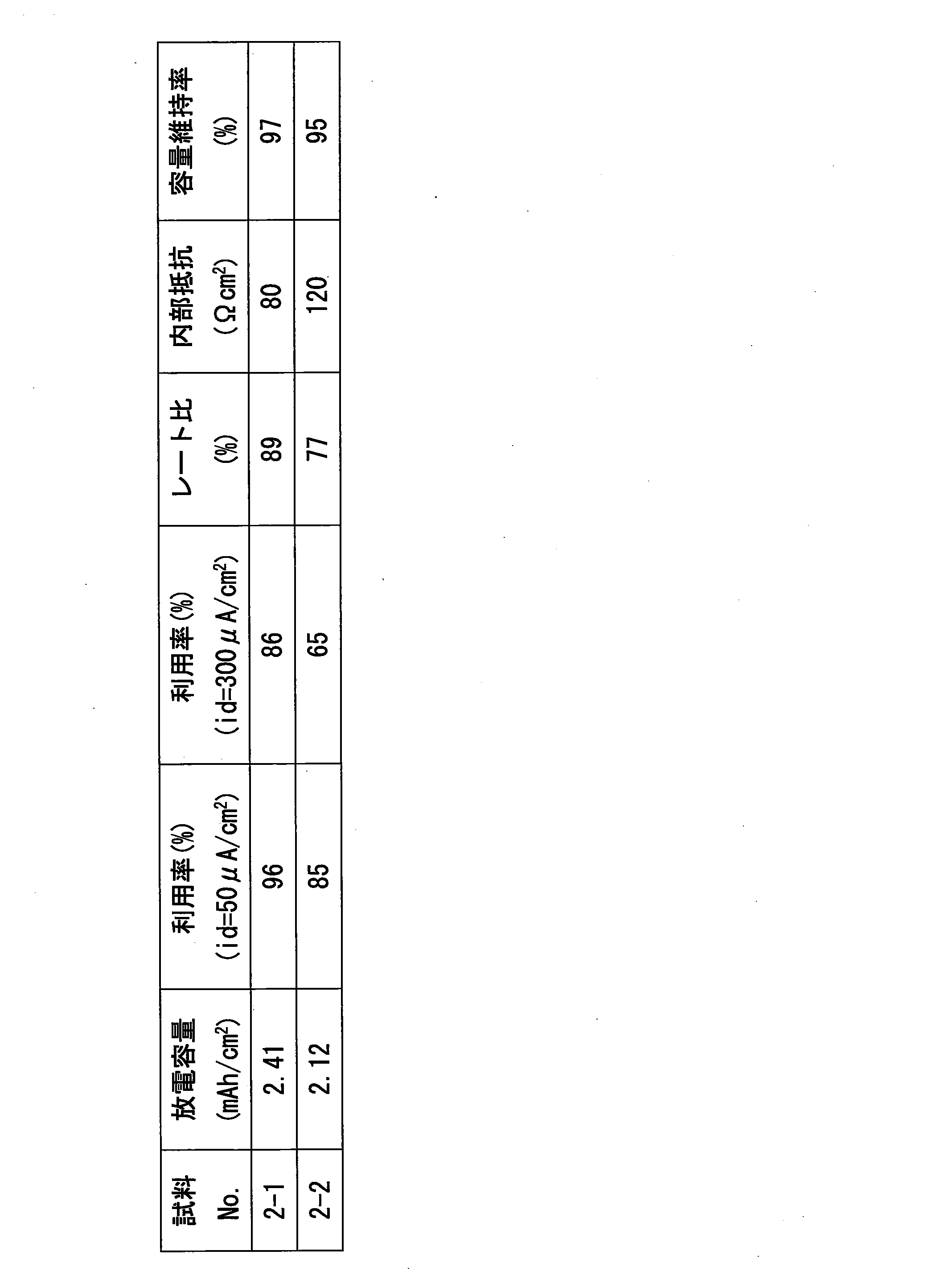
- each manufactured battery was evaluated in the same manner as in Example 1. The results are shown in Table 4.
- the battery of sample No. 2-1 has an initial discharge capacity of 2 mAh / cm 2 or more, a negative electrode utilization rate of 80% or more, and a rate ratio of 80% or more at current densities of 50 ⁇ A / cm 2 and 300 ⁇ A / cm 2 , respectively.
- the internal resistance was less than 100 ⁇ cm 2 , the capacity and rate characteristics were high, and the internal resistance was small.
- the battery of sample No. 2-2 has a lower negative electrode utilization rate of less than 80% at a high current (current density of 300 ⁇ A / cm 2 ) compared to the battery of sample No. 2-1, and the rate It was found that the characteristics deteriorated. Furthermore, it was found that the battery of sample No. 2-2 had a large internal resistance of 100 ⁇ cm 2 or more.
- Example 3 A battery was prepared in which the content of the powder of the negative electrode active material in the negative electrode layer was changed in the range of 30 to 80% by mass, and the battery performance was evaluated.
- the battery was the same as Sample No. 1-3 except that the negative electrode member was produced by changing the content of the Li 4 Ti 5 O 12 powder to 30%, 40%, 70%, and 80% by mass. Were prepared. However, the thickness of each negative electrode layer is 280 ⁇ m in the case of 30% by mass, 200 ⁇ m in the case of 40% by mass, 100 ⁇ m in the case of 70% by mass, so that the theoretical capacity of the whole negative electrode layer is equal. In the case of 80 mass%, it was set to 80 ⁇ m. These batteries were incorporated into a charge / discharge test cell, and these were designated as Sample No. 3-1, Sample No. 3-2, Sample No. 3-3, and Sample No. 3-4.
- Table 5 shows the configuration of each battery fabricated.
- each manufactured battery was evaluated in the same manner as in Example 1. The results are shown in Table 6.
- the batteries of Sample No. 3-1 to Sample No. 3-4 had a discharge capacity maintenance rate of 50% or more at 96th cycle and were excellent in charge / discharge cycle characteristics.
- the batteries of Sample No. 3-2 and Sample No. 3-3 having a negative electrode active material content of 40 mass% and 70 mass% have an initial discharge capacity of 2 mAh / cm 2 or more and a current density of 50 ⁇ A / cm 2.
- the utilization ratio of the negative electrode at 80 ⁇ A / cm 2 was 80% or more, the rate ratio was 80% or more, the internal resistance was less than 100 ⁇ cm 2 , the capacity and rate characteristics were high, and the internal resistance was small.
- sample No. 3-4 having a negative electrode active material content of 30% by mass or 80% by mass has a large internal resistance of 100 ⁇ cm 2 or more
- the battery of sample No. 3-4 has an initial discharge capacity of less than 2 mAh / cm 2 and a negative electrode utilization rate of less than 80% at current densities of 50 ⁇ A / cm 2 and 300 ⁇ A / cm 2 , respectively. It was found that the characteristics deteriorated.
- Example 4 A battery in which the material of the negative electrode active material was changed was produced, and the battery performance was evaluated.
- a battery was fabricated in the same manner as Sample No. 1-3, except that the negative electrode member was fabricated by changing the Li 4 Ti 5 O 12 powder to a hard carbon powder (average particle size 5 ⁇ m). However, the thickness of the negative electrode layer was 80 ⁇ m. This battery was incorporated in a charge / discharge test cell, and this was designated as Sample No. 4-1.
- a battery was fabricated in the same manner as Sample No. 4-1, except that the negative electrode member was fabricated by changing the hard carbon powder to graphite powder (average particle size: 5 ⁇ m). This battery was incorporated in a charge / discharge test cell, and this was designated as Sample No. 4-2.
- Table 7 shows the configuration of each battery fabricated.
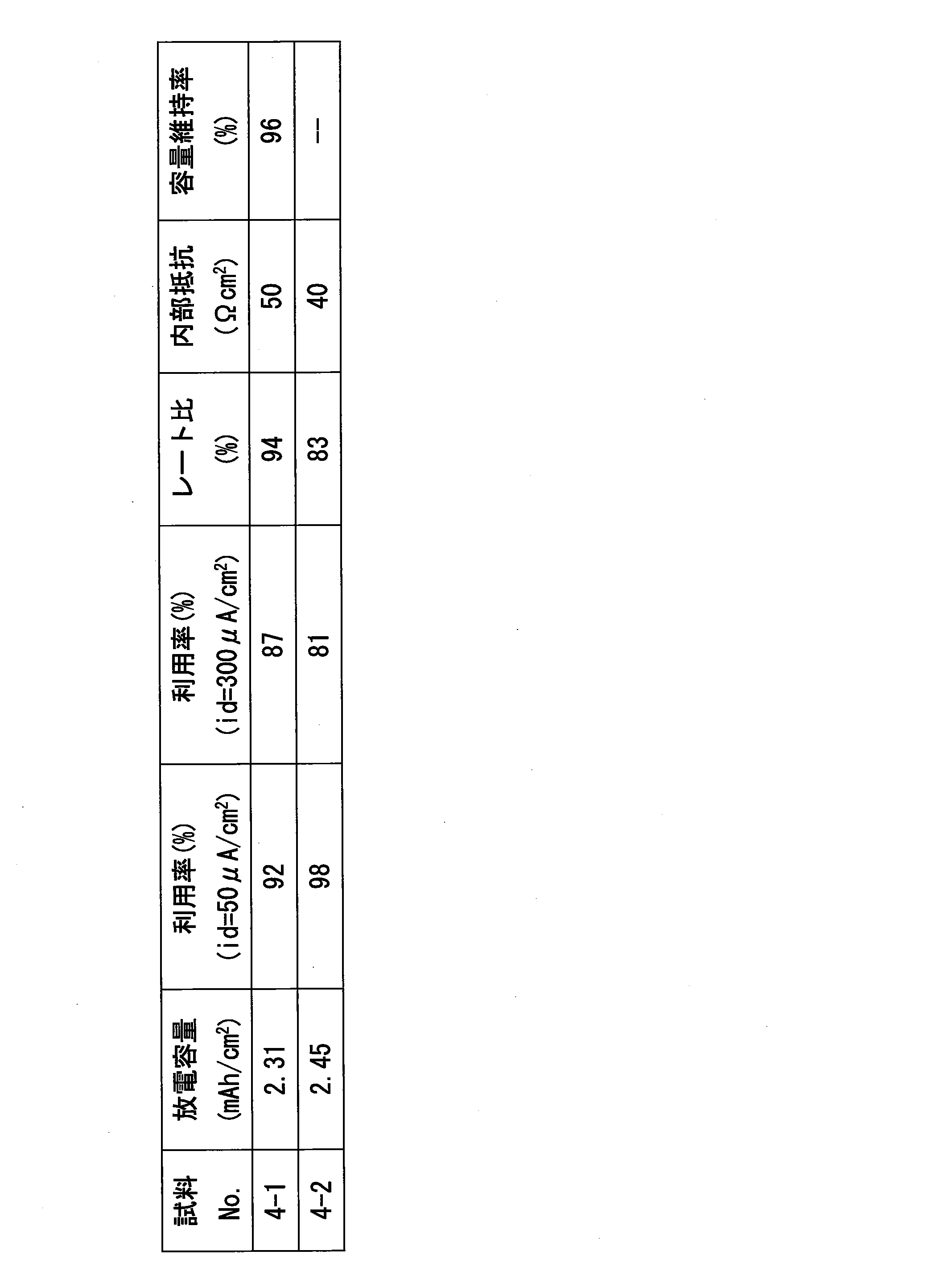
- each manufactured battery was evaluated in the same manner as in Example 1. The results are shown in Table 8.
- the cut-off voltage was set to 3.0 V to 4.2 V, as in the case of graphite.
- the battery of Sample No. 4-1 in which the negative electrode active material was hard carbon could operate stably for 50 cycles or more without causing an internal short circuit, and the discharge capacity at the 50th cycle. It was found that the maintenance rate was as high as 96% or more and the charge / discharge cycle characteristics were excellent.
- the battery of sample No. 4-1 has an initial discharge capacity of 2 mAh / cm 2 or more, a negative electrode utilization rate of 80% or more, and a rate ratio of 80% or more at current densities of 50 ⁇ A / cm 2 and 300 ⁇ A / cm 2 , respectively. It was found that the internal resistance was less than 100 ⁇ cm 2 , the capacity and rate characteristics were high, and the internal resistance was small.
- the battery of sample No. 4-2 whose negative electrode active material is graphite like the battery of sample No. 1-2, was confirmed to be unable to charge up to 4.2V before reaching 50 cycles. A short circuit seems to have occurred.
- the positive electrode active material eg, LiNi 0.8 Co 0.15 Al having a small volume change rate during charge / discharge (volume change rate of 1% or less) and fine particles (average particle diameter of 6 ⁇ m or less). It can be seen that by using 0.05 O 2 ), the expansion and contraction of the positive electrode layer accompanying charge / discharge can be suppressed, and the charge / discharge cycle characteristics can be further improved.
- the nonaqueous electrolyte battery of the present invention can be used, for example, as a power source for an electric vehicle as well as a mobile phone, a notebook computer, a digital camera.
Landscapes
- Chemical & Material Sciences (AREA)
- Chemical Kinetics & Catalysis (AREA)
- Electrochemistry (AREA)
- General Chemical & Material Sciences (AREA)
- Inorganic Chemistry (AREA)
- Engineering & Computer Science (AREA)
- Manufacturing & Machinery (AREA)
- General Physics & Mathematics (AREA)
- Condensed Matter Physics & Semiconductors (AREA)
- Physics & Mathematics (AREA)
- Materials Engineering (AREA)
- Battery Electrode And Active Subsutance (AREA)
- Secondary Cells (AREA)
Abstract
Description
本発明の非水電解質電池(リチウム系電池)を作製し、その電池性能を評価した。
Li4Ti5O12の粉末(平均粒径1μm)とLi2S‐P2S5系固体電解質の粉末(平均粒径1~5μm)とを質量比で50:50となるように混合して負極合剤を作製した。次いで、負極集電体となるSUS316Lの箔(厚さ10μm)を金型に配置し、その上から負極合剤を充填した後、これを360MPaの圧力で加圧成形して、負極集電体の上に負極層(Li4Ti5O12+Li2S‐P2S5系固体電解質の成形体)が形成された負極部材を作製した。この負極部材における負極層の厚さは、60μmであった。Li2S‐P2S5系固体電解質には、Li2SとP2S5とをモル比で4:1の割合でボールミリング混合した後、Ar雰囲気中で240℃×1時間の熱処理をしたものを用いた。
作製した各電池の構成を表1に示す。また、作製した各電池について、以下の評価を行った。その結果を表2に示す。
1回の充放電を1サイクルとする充放電サイクル試験を実施し、充放電サイクル特性(容量維持率)を調べた。なお、充放電サイクル試験の条件は、室温(約25℃)、負極活物質がLi4Ti5O12の場合、カットオフ電圧(放電終止電圧~充電終止電圧)を1.0V~3.5V、負極活物質がグラファイトの場合、カットオフ電圧を3.0V~4.2Vとし、いずれの場合も電流密度(id)を50μA/cm2の定電流とした。また、容量維持率は、50サイクル目の放電容量を1サイクル目の初期放電容量で除して求めた。各電池の初期放電容量及び容量維持率を表2に示す。
上記した充放電サイクル試験での初期放電容量から電流密度が50μA/cm2の場合の負極の利用率を調べた。また、上記した試験条件において、電流密度を300μA/cm2の定電流としたときの初期放電容量から電流密度が300μA/cm2の場合の負極の利用率を調べた。なお、利用率は、放電容量を負極の理論容量で除して求めた。負極の理論容量は、負極活物質の単位体積当たりの理論容量と、負極層に含有する負極活物質の体積との積とした。それぞれの電流密度(id=50μA/cm2、300μA/cm2)における各電池の負極利用率を表2に示す。
電流密度を50μA/cm2の定電流としたときの初期放電容量と、電流密度を300μA/cm2の定電流としたときの初期放電容量とからレート比を調べた。なお、レート比は、電流密度が300μA/cm2の場合の放電容量を電流密度が50μA/cm2の場合の放電容量で除して求めた。各電池のレート比を表2に示す。
上記した充放電サイクル試験での1サイクル目において、充電終止電圧まで充電した満充電状態から50μA/cm2の定電流で放電を開始し、放電開始から所定時間経過後の放電電圧を測定して内部抵抗を調べた。なお、内部抵抗は、充電終止電圧からこの放電電圧を減じた電圧を1/2にした後、これを50μA/cm2で除して求めた。各電池の内部抵抗を表2に示す。

負極活物質の粉末の平均粒径を変更した電池を作製し、その電池性能を評価した。
負極層における負極活物質の粉末の含有量を30~80質量%の範囲で変更した電池を作製し、その電池性能を評価した。


負極活物質の材料を変更した電池を作製し、その電池性能を評価した。

Claims (5)
- 正極層と負極層、及びこれら両層の間に介在される固体電解質層を有する非水電解質電池であって、
前記負極層は、負極活物質の粉末と固体電解質の粉末とを含有し、
前記負極活物質は、充放電時の体積変化率が1%以下、かつ、粉末の平均粒径が8μm以下であり、
前記固体電解質層は、気相法により形成されていることを特徴とする非水電解質電池。 - 前記負極活物質が、Li4Ti5O12又は難黒鉛化炭素であることを特徴とする請求項1に記載の非水電解質電池。
- 前記負極層に含有する前記固体電解質が、硫化物系固体電解質であることを特徴とする請求項1又は2に記載の非水電解質電池。
- 前記負極層における前記負極活物質の粉末の含有量が、30質量%以上80質量%以下であることを特徴とする請求項1~3のいずれか一項に記載の非水電解質電池。
- 前記固体電解質層が、硫化物系固体電解質を含有することを特徴とする請求項1~4のいずれか一項に記載の非水電解質電池。
Priority Applications (5)
| Application Number | Priority Date | Filing Date | Title |
|---|---|---|---|
| DE112012000513T DE112012000513T5 (de) | 2011-01-19 | 2012-01-18 | Nichtwässrige Elektrolytbatterie |
| US13/980,082 US20130302698A1 (en) | 2011-01-19 | 2012-01-18 | Nonaqueous electrolyte battery |
| CN201280005819.6A CN103329334B (zh) | 2011-01-19 | 2012-01-18 | 非水电解质电池 |
| KR1020137015910A KR20130143609A (ko) | 2011-01-19 | 2012-01-18 | 비수 전해질 전지 |
| JP2012504977A JP5376412B2 (ja) | 2011-01-19 | 2012-01-18 | 非水電解質電池 |
Applications Claiming Priority (2)
| Application Number | Priority Date | Filing Date | Title |
|---|---|---|---|
| JP2011009308 | 2011-01-19 | ||
| JP2011-009308 | 2011-01-19 |
Publications (1)
| Publication Number | Publication Date |
|---|---|
| WO2012099178A1 true WO2012099178A1 (ja) | 2012-07-26 |
Family
ID=46515800
Family Applications (1)
| Application Number | Title | Priority Date | Filing Date |
|---|---|---|---|
| PCT/JP2012/050987 Ceased WO2012099178A1 (ja) | 2011-01-19 | 2012-01-18 | 非水電解質電池 |
Country Status (6)
| Country | Link |
|---|---|
| US (1) | US20130302698A1 (ja) |
| JP (1) | JP5376412B2 (ja) |
| KR (1) | KR20130143609A (ja) |
| CN (1) | CN103329334B (ja) |
| DE (1) | DE112012000513T5 (ja) |
| WO (1) | WO2012099178A1 (ja) |
Cited By (12)
| Publication number | Priority date | Publication date | Assignee | Title |
|---|---|---|---|---|
| JP2014072135A (ja) * | 2012-10-01 | 2014-04-21 | Toyota Motor Corp | 固体電池およびその製造方法 |
| WO2015152214A1 (ja) * | 2014-03-31 | 2015-10-08 | 株式会社クレハ | 全固体電池用負極及びそれを含む全固体電池 |
| WO2015152215A1 (ja) * | 2014-03-31 | 2015-10-08 | 株式会社クレハ | 全固体電池用負極電極の製造方法及び全固体電池用負極電極 |
| JP2017120729A (ja) * | 2015-12-28 | 2017-07-06 | トヨタ自動車株式会社 | 二次電池 |
| JP2019016516A (ja) * | 2017-07-06 | 2019-01-31 | トヨタ自動車株式会社 | 全固体リチウムイオン二次電池 |
| JP2019135701A (ja) * | 2018-02-05 | 2019-08-15 | 株式会社豊田中央研究所 | 二次電池 |
| JP2021128884A (ja) * | 2020-02-14 | 2021-09-02 | トヨタ自動車株式会社 | 全固体電池用負極 |
| JP2021128885A (ja) * | 2020-02-14 | 2021-09-02 | トヨタ自動車株式会社 | 全固体電池用負極 |
| JP2021128883A (ja) * | 2020-02-14 | 2021-09-02 | トヨタ自動車株式会社 | 全固体電池用負極 |
| JP2022153951A (ja) * | 2021-03-30 | 2022-10-13 | トヨタ自動車株式会社 | 全固体電池 |
| US11600846B2 (en) | 2017-07-06 | 2023-03-07 | Toyota Jidosha Kabushiki Kaisha | All-solid-state lithium ion secondary battery |
| JP2023544414A (ja) * | 2020-10-02 | 2023-10-23 | ネクステック バッテリーズ、インコーポレイテッド | リチウムイオン伝導性固体電解質を含む電池セル及びその製造方法 |
Families Citing this family (12)
| Publication number | Priority date | Publication date | Assignee | Title |
|---|---|---|---|---|
| EP2945211B1 (en) * | 2014-05-15 | 2018-11-21 | Saft Groupe S.A. | Lithium titanate oxide as negative electrode in li-ion cells |
| CN105489931A (zh) * | 2015-12-24 | 2016-04-13 | 国联汽车动力电池研究院有限责任公司 | 硫化物电解质在制备全固态电池中的应用 |
| US20190305293A1 (en) * | 2016-12-26 | 2019-10-03 | Showa Denko K. K. | All-solid-state lithium ion battery |
| JP6841249B2 (ja) * | 2018-02-14 | 2021-03-10 | トヨタ自動車株式会社 | 全固体電池の製造方法 |
| JP7048466B2 (ja) * | 2018-09-19 | 2022-04-05 | 太陽誘電株式会社 | 全固体電池 |
| DE102018222142A1 (de) * | 2018-12-18 | 2020-06-18 | Fraunhofer-Gesellschaft zur Förderung der angewandten Forschung e.V. | Verfahren zum Herstellen einer Festelektrolytmembran oder einer Anode und Festelektrolytmembran oder Anode |
| JP7056598B2 (ja) * | 2019-02-05 | 2022-04-19 | トヨタ自動車株式会社 | 負極層および全固体電池 |
| JP7059951B2 (ja) * | 2019-02-05 | 2022-04-26 | トヨタ自動車株式会社 | 負極層および全固体電池 |
| CN110098379B (zh) * | 2019-04-25 | 2021-08-17 | 浙江锋锂新能源科技有限公司 | 一种锂金属负极及其制备方法和使用该负极的锂电池 |
| JP7545429B2 (ja) * | 2022-02-07 | 2024-09-04 | トヨタ自動車株式会社 | 負極層 |
| CN116404101B (zh) * | 2023-06-08 | 2023-08-18 | 深圳海辰储能控制技术有限公司 | 一种负极极片、电池、电池包及用电设备 |
| CN120955082A (zh) | 2024-05-14 | 2025-11-14 | 通用汽车环球科技运作有限责任公司 | 用于硫化物全固态电池的氧化物固体电解质涂覆的镍基正极 |
Citations (5)
| Publication number | Priority date | Publication date | Assignee | Title |
|---|---|---|---|---|
| JPH08180903A (ja) * | 1994-12-22 | 1996-07-12 | Sanyo Electric Co Ltd | リチウム二次電池 |
| JP2008091328A (ja) * | 2006-09-04 | 2008-04-17 | Sumitomo Electric Ind Ltd | リチウム二次電池およびその製造方法 |
| JP2008103282A (ja) * | 2006-10-20 | 2008-05-01 | Idemitsu Kosan Co Ltd | 極材及びそれを用いた固体二次電池 |
| JP2008270137A (ja) * | 2007-03-23 | 2008-11-06 | Toyota Motor Corp | 合材層およびその製造方法ならびに固体電池およびその製造方法 |
| JP2009054596A (ja) * | 2008-10-30 | 2009-03-12 | Ohara Inc | リチウムイオン二次電池及びその製造方法 |
Family Cites Families (8)
| Publication number | Priority date | Publication date | Assignee | Title |
|---|---|---|---|---|
| US5478671A (en) * | 1992-04-24 | 1995-12-26 | Fuji Photo Film Co., Ltd. | Nonaqueous secondary battery |
| JP3453099B2 (ja) | 2000-03-27 | 2003-10-06 | 大阪府 | リチウム系二次電池の製造方法 |
| JP3690684B2 (ja) | 2003-04-18 | 2005-08-31 | 松下電器産業株式会社 | 固体電解質およびそれを含んだ全固体電池 |
| US7960057B2 (en) * | 2004-05-17 | 2011-06-14 | Toyota Motor Engineering & Manufacturing North America, Inc. | Battery with molten salt electrolyte and phosphorus-containing cathode |
| US7541016B2 (en) * | 2006-04-11 | 2009-06-02 | Enerdel, Inc. | Lithium titanate and method of forming the same |
| CN1978524A (zh) * | 2006-11-23 | 2007-06-13 | 东北师范大学 | 快充电池材料钛酸锂和钛酸锂/聚并苯复合物的制备方法 |
| JP2009199920A (ja) | 2008-02-22 | 2009-09-03 | Sumitomo Electric Ind Ltd | リチウム電池 |
| JP5187502B2 (ja) * | 2008-03-06 | 2013-04-24 | 住友電気工業株式会社 | リチウム電池 |
-
2012
- 2012-01-18 JP JP2012504977A patent/JP5376412B2/ja active Active
- 2012-01-18 DE DE112012000513T patent/DE112012000513T5/de not_active Withdrawn
- 2012-01-18 CN CN201280005819.6A patent/CN103329334B/zh active Active
- 2012-01-18 US US13/980,082 patent/US20130302698A1/en not_active Abandoned
- 2012-01-18 WO PCT/JP2012/050987 patent/WO2012099178A1/ja not_active Ceased
- 2012-01-18 KR KR1020137015910A patent/KR20130143609A/ko not_active Withdrawn
Patent Citations (5)
| Publication number | Priority date | Publication date | Assignee | Title |
|---|---|---|---|---|
| JPH08180903A (ja) * | 1994-12-22 | 1996-07-12 | Sanyo Electric Co Ltd | リチウム二次電池 |
| JP2008091328A (ja) * | 2006-09-04 | 2008-04-17 | Sumitomo Electric Ind Ltd | リチウム二次電池およびその製造方法 |
| JP2008103282A (ja) * | 2006-10-20 | 2008-05-01 | Idemitsu Kosan Co Ltd | 極材及びそれを用いた固体二次電池 |
| JP2008270137A (ja) * | 2007-03-23 | 2008-11-06 | Toyota Motor Corp | 合材層およびその製造方法ならびに固体電池およびその製造方法 |
| JP2009054596A (ja) * | 2008-10-30 | 2009-03-12 | Ohara Inc | リチウムイオン二次電池及びその製造方法 |
Cited By (21)
| Publication number | Priority date | Publication date | Assignee | Title |
|---|---|---|---|---|
| JP2014072135A (ja) * | 2012-10-01 | 2014-04-21 | Toyota Motor Corp | 固体電池およびその製造方法 |
| WO2015152214A1 (ja) * | 2014-03-31 | 2015-10-08 | 株式会社クレハ | 全固体電池用負極及びそれを含む全固体電池 |
| WO2015152215A1 (ja) * | 2014-03-31 | 2015-10-08 | 株式会社クレハ | 全固体電池用負極電極の製造方法及び全固体電池用負極電極 |
| CN106133953A (zh) * | 2014-03-31 | 2016-11-16 | 株式会社吴羽 | 全固态电池用负极以及包含其的全固态电池 |
| JPWO2015152215A1 (ja) * | 2014-03-31 | 2017-04-13 | 株式会社クレハ | 全固体電池用負極電極の製造方法及び全固体電池用負極電極 |
| JPWO2015152214A1 (ja) * | 2014-03-31 | 2017-04-13 | 株式会社クレハ | 全固体電池用負極及びそれを含む全固体電池 |
| US9947927B2 (en) | 2014-03-31 | 2018-04-17 | Kureha Corporation | Production method for negative electrode for all-solid-state battery, and negative electrode for all-solid-state battery |
| CN106133953B (zh) * | 2014-03-31 | 2019-06-25 | 株式会社吴羽 | 全固态电池用负极以及包含其的全固态电池 |
| JP2017120729A (ja) * | 2015-12-28 | 2017-07-06 | トヨタ自動車株式会社 | 二次電池 |
| US11600846B2 (en) | 2017-07-06 | 2023-03-07 | Toyota Jidosha Kabushiki Kaisha | All-solid-state lithium ion secondary battery |
| JP2019016516A (ja) * | 2017-07-06 | 2019-01-31 | トヨタ自動車株式会社 | 全固体リチウムイオン二次電池 |
| US10777841B2 (en) | 2017-07-06 | 2020-09-15 | Toyota Jidosha Kabushiki Kaisha | All-solid-state lithium ion secondary battery |
| JP2019135701A (ja) * | 2018-02-05 | 2019-08-15 | 株式会社豊田中央研究所 | 二次電池 |
| JP7087422B2 (ja) | 2018-02-05 | 2022-06-21 | トヨタ自動車株式会社 | 二次電池 |
| JP2021128885A (ja) * | 2020-02-14 | 2021-09-02 | トヨタ自動車株式会社 | 全固体電池用負極 |
| JP2021128883A (ja) * | 2020-02-14 | 2021-09-02 | トヨタ自動車株式会社 | 全固体電池用負極 |
| JP2021128884A (ja) * | 2020-02-14 | 2021-09-02 | トヨタ自動車株式会社 | 全固体電池用負極 |
| JP7334647B2 (ja) | 2020-02-14 | 2023-08-29 | トヨタ自動車株式会社 | 全固体電池用負極 |
| JP2023544414A (ja) * | 2020-10-02 | 2023-10-23 | ネクステック バッテリーズ、インコーポレイテッド | リチウムイオン伝導性固体電解質を含む電池セル及びその製造方法 |
| JP2022153951A (ja) * | 2021-03-30 | 2022-10-13 | トヨタ自動車株式会社 | 全固体電池 |
| JP7484790B2 (ja) | 2021-03-30 | 2024-05-16 | トヨタ自動車株式会社 | 全固体電池 |
Also Published As
| Publication number | Publication date |
|---|---|
| DE112012000513T5 (de) | 2013-10-24 |
| CN103329334A (zh) | 2013-09-25 |
| KR20130143609A (ko) | 2013-12-31 |
| CN103329334B (zh) | 2016-02-03 |
| US20130302698A1 (en) | 2013-11-14 |
| JP5376412B2 (ja) | 2013-12-25 |
| JPWO2012099178A1 (ja) | 2014-06-30 |
Similar Documents
| Publication | Publication Date | Title |
|---|---|---|
| JP5376412B2 (ja) | 非水電解質電池 | |
| CN111566848B (zh) | 负极材料和使用它的电池 | |
| CN101828295B (zh) | 非水电解质二次电池及其制造方法 | |
| Lai et al. | Ultrahigh‐energy‐density microbatteries enabled by new electrode architecture and micropackaging design | |
| KR102198115B1 (ko) | 전극, 그의 제조 방법, 전지, 및 전자 기기 | |
| CN106165178B (zh) | 具有复合固体电解质的Li/金属电池 | |
| JP5348607B2 (ja) | 全固体リチウム二次電池 | |
| CN111566864A (zh) | 电池 | |
| CN111557057A (zh) | 正极材料和使用它的电池 | |
| CN103988346A (zh) | 全固体电池 | |
| WO2019146296A1 (ja) | 正極材料およびそれを用いた電池 | |
| JPWO2012026480A1 (ja) | 非水電解質電池、およびその製造方法 | |
| JP2011086554A (ja) | 非水電解質電池 | |
| WO2022057189A1 (zh) | 一种固态电池、电池模组、电池包及其相关的装置 | |
| CN111987365A (zh) | 具有高能量密度的全固态电池及其制造方法 | |
| CN112602208B (zh) | 全固态电池的电极和制造包括该电极的电极组件的方法 | |
| JP2012243645A (ja) | 電極、および全固体型非水電解質電池 | |
| JPWO2011043267A1 (ja) | 非水電解質電池 | |
| CN116314654A (zh) | 一种全固态锂离子电池及其制备方法 | |
| JP2013109881A (ja) | 非水電解質電池用電極、及び非水電解質電池、並びに電動車両 | |
| JP5454459B2 (ja) | 非水電解質電池 | |
| US20220052375A1 (en) | Battery | |
| US20250349976A1 (en) | Solid-state electrolyte membrane and preparation method thereof, solid-state battery, and electric apparatus | |
| CN114583245B (zh) | 全固体二次电池 | |
| JP2013089417A (ja) | 非水電解質電池 |
Legal Events
| Date | Code | Title | Description |
|---|---|---|---|
| WWE | Wipo information: entry into national phase |
Ref document number: 2012504977 Country of ref document: JP |
|
| 121 | Ep: the epo has been informed by wipo that ep was designated in this application |
Ref document number: 12736891 Country of ref document: EP Kind code of ref document: A1 |
|
| ENP | Entry into the national phase |
Ref document number: 20137015910 Country of ref document: KR Kind code of ref document: A |
|
| WWE | Wipo information: entry into national phase |
Ref document number: 13980082 Country of ref document: US |
|
| WWE | Wipo information: entry into national phase |
Ref document number: 1120120005139 Country of ref document: DE Ref document number: 112012000513 Country of ref document: DE |
|
| 122 | Ep: pct application non-entry in european phase |
Ref document number: 12736891 Country of ref document: EP Kind code of ref document: A1 |