WO2012090329A1 - Dispositif de ceinture de sécurité - Google Patents
Dispositif de ceinture de sécurité Download PDFInfo
- Publication number
- WO2012090329A1 WO2012090329A1 PCT/JP2010/073808 JP2010073808W WO2012090329A1 WO 2012090329 A1 WO2012090329 A1 WO 2012090329A1 JP 2010073808 W JP2010073808 W JP 2010073808W WO 2012090329 A1 WO2012090329 A1 WO 2012090329A1
- Authority
- WO
- WIPO (PCT)
- Prior art keywords
- webbing
- dilatant characteristic
- dilatant
- characteristic portion
- passage hole
- Prior art date
Links
Images


Classifications
-
- B—PERFORMING OPERATIONS; TRANSPORTING
- B60—VEHICLES IN GENERAL
- B60R—VEHICLES, VEHICLE FITTINGS, OR VEHICLE PARTS, NOT OTHERWISE PROVIDED FOR
- B60R22/00—Safety belts or body harnesses in vehicles
- B60R22/12—Construction of belts or harnesses
-
- F—MECHANICAL ENGINEERING; LIGHTING; HEATING; WEAPONS; BLASTING
- F16—ENGINEERING ELEMENTS AND UNITS; GENERAL MEASURES FOR PRODUCING AND MAINTAINING EFFECTIVE FUNCTIONING OF MACHINES OR INSTALLATIONS; THERMAL INSULATION IN GENERAL
- F16F—SPRINGS; SHOCK-ABSORBERS; MEANS FOR DAMPING VIBRATION
- F16F7/00—Vibration-dampers; Shock-absorbers
- F16F7/08—Vibration-dampers; Shock-absorbers with friction surfaces rectilinearly movable along each other
-
- B—PERFORMING OPERATIONS; TRANSPORTING
- B60—VEHICLES IN GENERAL
- B60R—VEHICLES, VEHICLE FITTINGS, OR VEHICLE PARTS, NOT OTHERWISE PROVIDED FOR
- B60R22/00—Safety belts or body harnesses in vehicles
- B60R22/18—Anchoring devices
- B60R2022/1812—Connections between seat belt and buckle tongue
-
- F—MECHANICAL ENGINEERING; LIGHTING; HEATING; WEAPONS; BLASTING
- F16—ENGINEERING ELEMENTS AND UNITS; GENERAL MEASURES FOR PRODUCING AND MAINTAINING EFFECTIVE FUNCTIONING OF MACHINES OR INSTALLATIONS; THERMAL INSULATION IN GENERAL
- F16F—SPRINGS; SHOCK-ABSORBERS; MEANS FOR DAMPING VIBRATION
- F16F2224/00—Materials; Material properties
- F16F2224/04—Fluids
- F16F2224/041—Dilatant
Definitions
- the present invention relates to a seat belt device for restraining the body of an occupant seated on a seat with a webin.
- an object of the present invention is to provide a seat belt device that can prevent or suppress the movement of the webbing from the shoulder side to the lap side when the webbing is pulled without particularly increasing the strength of the webbing. It is.
- the seat belt device has a longitudinal intermediate portion that passes through a passage hole formed in the tongue, and the tongue is movably provided in the longitudinal direction.
- a lap webbing that restrains the occupant's waist at one end in the longitudinal direction from the passage hole, and a webbing that becomes a shoulder webbing that restrains the chest and shoulders of the occupant at the other end in the longitudinal direction from the passage hole
- a dilatant comprising a material having a dilatant characteristic that is provided in a region including a portion of the webbing located inside the passage hole in the mounted state and hardens when a load of a predetermined size or more acts. And a characteristic part.
- the webbing when the webbing is wound around the occupant's body and the tongue provided on the webbing is inserted into the buckle in this state, the webbing is attached to the occupant's body. Become. In this wearing state, one end of the webbing in the longitudinal direction from the tongue passage hole becomes a lap webbing to restrain the waist of the occupant, and the other end in the longitudinal direction from the tongue passage hole becomes a shoulder webbing to occupant Restrain the chest and shoulders.
- the dilatant characteristic portion is provided in the webbing.
- the dilatant characteristic portion is located in a region including a portion located inside the through hole formed in the tongue in the webbing.
- the dilatant characteristic part provided on the webbing is composed of a material having a dilatant characteristic that hardens when a load of a predetermined size or more is applied, so that the pressing reaction force from the inner peripheral part of the passage hole is dilatanted. When the characteristic part receives, the dilatant characteristic part hardens.
- the webbing when the webbing is pulled as described above, the webbing is supported by the portion of the tongue passing through the through hole and the dilatant characteristic part cured in the vicinity thereof, so that the strength of the webbing itself is not particularly increased.
- the webbing can withstand the pressing reaction force (that is, load) from the inner periphery of the passage hole.
- a seat belt device is the seat belt device according to the first aspect of the present invention, wherein the webbing is mounted on the occupant's body up to a region closer to the lap webbing than the passage hole.
- the dilatant characteristic portion is provided.
- the dilatant characteristic portion is located from the tongue passage hole to the lap webbing side. For this reason, the thickness of the lap webbing is increased by the amount provided with the dilatant characteristic portion. In this way, by increasing the thickness of the lap webbing, it is possible to reduce so-called “slack” of the lap webbing when the occupant wears the webbing.
- the seatbelt device is the seatbelt device according to the first aspect of the present invention, in which the webbing is passed to the shoulder webbing side from the passage hole in a state where the webbing is attached to the body of the occupant.
- the dilatant characteristic part is provided in a region and in the vicinity of the passage hole.
- the dilatant characteristic portion in a state where the webbing is mounted on the occupant's body, the dilatant characteristic portion is located closer to the passage hole on the shoulder webbing side than the passage hole of the tongue. For this reason, most of the shoulder webbing is not provided with the dilatant characteristic part, so that the majority of the shoulder webbing does not swell due to the provision of the dilatant characteristic part, and has a simple band shape. Thereby, when a passenger
- the dilatant characteristic portion does not protrude greatly toward the shoulder webbing side, so the cost is also low.
- a seat belt device is the seat belt device according to any one of the first to third aspects, wherein the webbing is folded back at one end side of the webbing, In the state where the dilatant characteristic portion is disposed between the other end side of the webbing and one end side of the webbing with respect to the folding position, the other end side of the webbing and the folding position than the folding position.
- One end side of the webbing is overlapped and the periphery of the dilatant characteristic portion in the webbing is stitched.
- the webbing is folded at one end side of the webbing, and between the other end side of the webbing from the folded position and the one end side of the webbing from the folded position.
- the dilatant characteristic portion is disposed in In this state, the other end side and one end side of the webbing are overlapped with respect to the folding position, and the one end side and the other end side of the webbing overlapped around the dilatant characteristic portion are stitched. Thereby, a dilatant characteristic part is provided in webbing.
- a seatbelt device is the seatbelt apparatus according to any one of the first to third aspects, wherein the webbing is formed in a bag shape opened at one end thereof, and In a state where the dilatant characteristic portion is inserted into the webbing from the opening, one end side of the webbing is stitched from the dilatant characteristic portion.
- the webbing is formed in a bag shape having one end opened, and the dilatant characteristic portion is inserted into the webbing from the opening.
- the webbing is sewn so as to close the opening at one end of the webbing while the dilatant characteristic portion is accommodated inside the webbing. Thereby, a dilatant characteristic part is provided in webbing.
- a seatbelt device is the seatbelt device according to any one of the first to third aspects, wherein the webbing is integrated with the dilatant characteristic portion on one surface in the thickness direction. Attached.
- the dilatant characteristic portion is integrally attached to one surface in the thickness direction of the webbing by stitching or adhesion. Thereby, a dilatant characteristic part is provided in webbing.
- a seat belt device is the seat belt device according to any one of the first to sixth aspects, wherein the width of the dilatant characteristic portion along the width direction of the webbing is determined.
- the dilatant characteristic part is provided on one side in the thickness direction of the webbing by setting it shorter than the width dimension of the webbing, and the notch part through which the dilatant characteristic part passes is connected to the passage hole. It is formed into a tongue.
- the width direction of the dilatant characteristic portion is along the width direction of the webbing, and the width dimension is set shorter than the width dimension of the webbing.
- a dilatant characteristic portion is provided on one side in the thickness direction.
- a passage hole through which the webbing passes is formed in the tongue, and further, a notch is formed in the tongue so as to communicate with the passage hole, and when the webbing passes through the passage hole, this notch is formed.
- the dilatant characteristic part passes.
- the seatbelt device according to the present invention as set forth in claim 8 is a hardened dilatant material having a dilatant characteristic that is cured by receiving a load in the present invention according to any one of claims 1 to 7.
- the dilatant characteristic portion is formed by covering with a covering portion that is more flexible than the dilatant characteristic portion main body in the state.
- the dilatant material having the dilatant characteristic is covered with a covering portion that is more flexible than the cured dilatant material. For this reason, even if the dilatant material is cured by receiving a load, since the flexible covering portion is interposed between the cured dilatant material and the occupant's body, the hardness of the dilatant material cured against the occupant's body Is difficult to communicate.
- a seat belt device is the seat belt device according to any one of the first to eighth aspects of the present invention, wherein the seat belt device includes an intermediate portion of the dilatant characteristic portion along the longitudinal direction of the webbing.
- the dilatant characteristic part By forming the dilatant characteristic part in a taper shape in which the width dimension of the dilatant characteristic part along the width direction of the webbing is gradually shortened toward at least one of the one end and the other end, the thickness dimension is provided by providing the dilatant characteristic part in the webbing.
- a notch through which the increased portion passes is formed in the tongue so as to communicate with the passage hole.
- the thickness dimension is increased at the portion where the dilatant characteristic portion is provided in the webbing.
- a notch connected to the passage hole is formed in the tongue corresponding to the portion where the thickness dimension is increased in the webbing, and the portion where the thickness dimension is increased by providing the dilatant characteristic portion in the webbing is one of them. Since the part passes through the notch, the shoulder webbing can be moved relatively smoothly from the shoulder webbing side or from the lap webbing side to the shoulder webbing side.
- the width dimension of the dilatant characteristic portion along the width direction of the webbing from the intermediate portion of the dilatant characteristic portion along the longitudinal direction of the webbing to at least one of the one end and the other end. It is formed in a tapered shape that becomes gradually shorter. For this reason, when the portion where the dilatant characteristic portion is provided in the webbing passes through the cutout portion, the dilatant characteristic portion passes from one end or the other end in the longitudinal direction whose width dimension is sufficiently shorter than the opening width of the cutout portion. .
- the dilatant characteristic portion is The portion provided with can be smoothly inserted into the notch and allowed to pass therethrough.
- the “intermediate part” of the “intermediate part of the dilatant characteristic part along the longitudinal direction of the webbing” means the inner side in the longitudinal direction from both ends of the dilatant characteristic part along the longitudinal direction of the webbing. It is not limited to the central part of the dilatant characteristic part along.
- the seatbelt device is configured such that the portion located inside the tongue passage hole in the webbing and the bending in the vicinity thereof are bent by the hardened dilatant characteristic portion.
- the music can be restricted, and the shoulder webbing can be prevented or suppressed from passing through the passage hole of the tongue and moving toward the occupant's waist.
- the webbing since the webbing is supported by the cured dilatant characteristic portion, the webbing can withstand the pressing reaction force (ie, load) from the inner peripheral portion of the passage hole without particularly increasing the strength of the webbing itself.
- the seat belt device can reduce the slack of the lap webbing, so-called “slack”, because the thickness of the lap webbing is increased by the amount of the dilatant characteristic portion.
- the seatbelt device improves the feeling that the occupant feels when the occupant wears the webbing, has a good appearance, and is low in cost.
- the dilatant characteristic portion can be provided integrally with the webbing in a state where the dilatant characteristic portion is provided inside the webbing.
- the dilatant characteristic portion can be integrally provided on one surface in the thickness direction of the webbing.
- the webbing is relatively smoothly performed from the shoulder webbing side to the lap webbing side or It can move from the webbing side to the shoulder webbing side.
- the portion where the dilatant characteristic portion is provided in the webbing easily enters the notch portion of the tongue.
- FIG. 1 is a front view from the front of a vehicle showing an outline of the overall configuration of a seatbelt device according to an embodiment of the present invention. It is a top view of the lap belt part in webbing.
- FIG. 3 is a cross-sectional view of the webbing along the line AA in FIG. 2. It is sectional drawing of the tongue in the mounting state of webbing, and its vicinity.
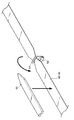
- It is a disassembled perspective view of webbing which shows the state before providing a dilatant characteristic part in webbing.
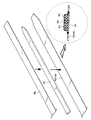
- It is a disassembled perspective view of the webbing which shows the modification of the state before providing a dilatant characteristic part in webbing.
- It is a disassembled perspective view of the webbing which shows the modification of the state before providing a dilatant characteristic part in webbing.
- It is a disassembled perspective view of the webbing which shows the modification of the state before providing a dilatant characteristic part in webbing.
- It is a disassembled perspective view of the webbing which shows the modification
- FIG. 1 shows a schematic front view of the overall configuration of a seat belt device 10 according to the present embodiment.
- the seat belt device 10 includes a retractor 12.
- the retractor 12 is fixed to the vehicle body, the frame 16 of the seat 14 and the like (vehicle body not shown in the present embodiment) on the side in the width direction of the seat 14 installed in the vehicle.
- a spool having an axial direction along the longitudinal direction of the vehicle is rotatably provided on the retractor 12, and a longitudinal base end portion of a webbing 18 formed in a long band shape is locked to the spool. Yes.
- the webbing 18 is stored in a state in which the base end side in the longitudinal direction is wound in a layered manner on the outer peripheral portion of the spool, and the tip end side thereof is pulled out upward of the vehicle. Further, the retractor 12 is provided with a lock mechanism (not shown) so that the spool is locked when the vehicle is suddenly decelerated and the rotation of the spool when the webbing 18 is pulled out of the spool is regulated. It has become.
- a shoulder anchor 20 is attached to the vehicle body above the retractor 12.
- the shoulder anchor 20 is formed with a slit hole penetrating generally in the width direction of the vehicle, and the webbing 18 drawn upward from the spool of the retractor 12 passes through the slit hole of the shoulder anchor 20 and is folded downward. .
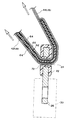
- a tongue 22 is provided on the webbing 18 on the front end side of the shoulder anchor 20 in the webbing 18. As shown in FIGS. 2 and 4, the tongue 22 is formed by covering a part of the core metal with a synthetic resin material with a metal plate material. The tongue 22 is formed with a passage hole 24 penetrating in the thickness direction. The longitudinal direction of the passage hole 24 is a slit shape along the width direction of the webbing 18, and the webbing 18 passes through the passage hole 24.
- the protruding portion from the synthetic resin material in the core of the tongue 22 is an insertion portion 26.
- the insertion portion 26 of the tongue 22 is inserted into the buckle 30 provided in The insertion part 26 is held by the buckle 30.
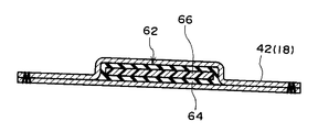
- a portion of the webbing 18 on the front end side than the passage hole 24 of the tongue 22 is used as a lap webbing 42 to restrain the waist portion of the occupant 28, and a portion of the webbing 18 on the proximal end side of the passage hole 24 of the tongue 22.
- the shoulder webbing 44 restrains the abdomen, chest and shoulders of the occupant 28.
- an anchor plate 52 is attached to the vehicle body, the frame 16 of the seat 14 or the like (a vehicle body not shown in the present embodiment) on the side of the seat 14 where the retractor 12 is provided.
- a slit hole 54 is formed in the anchor plate 52.
- the webbing 18 passes through the slit hole 54 and is folded back to the base end side in the longitudinal direction of the webbing 18 up to a portion that becomes the shoulder webbing 44 of the webbing 18. And are superimposed.
- a dilatant characteristic portion 62 is provided between the webbing 18 thus superposed.
- the dilatant characteristic portion 62 is a state where the occupant 28 inserts the insertion portion 26 of the tongue 22 into the buckle 30 and wears the webbing 18 on the body, and the webbing 18 side of the wrap webbing 42 through the passage hole 24 of the tongue 22. To the shoulder webbing 44 side.
- the dilatant characteristic portion 62 is folded back at the slit hole 54 in a state where it is placed on the base end side (or the distal end side) of the webbing 18 relative to the folding position at the slit hole 54.
- the dilatant characteristic part 62 is built in the webbing 18 by covering the front end side (or the base end side) of the position and stitching the webbing 18 so as to surround the dilatant characteristic part 62 from the outside.
- the dilatant characteristic portion 62 includes a covering portion 64.
- the covering portion 64 is formed of, for example, a rubber material or a flexible synthetic resin material having elasticity similar to that of a rubber material.
- the covering portion 64 is formed in a hollow shape whose longitudinal direction is along the longitudinal direction of the webbing 18.
- a portion from the predetermined position (longitudinal intermediate portion) on one end side in the longitudinal direction of the covering portion 64 to the one end portion is formed in a tapered shape in which the width dimension gradually decreases toward the one end side.
- a portion from the predetermined position (longitudinal intermediate portion) on the other end side in the longitudinal direction of the covering portion 64 to the other end portion is formed in a tapered shape in which the width dimension gradually decreases toward the other end side.
- a dilatant characteristic resin 66 as a dilatant characteristic material is provided inside the covering portion 64.
- the dilatant characteristic resin 66 is in a liquid state or a gel state in a normal state, but has a characteristic of being instantaneously cured when an external load is applied.
- the setting range of the dilatant characteristic portion 62 in the webbing 18 is such that a part of the dilatant characteristic portion 62 is within the passage hole 24 as shown in FIG. 4 when the webbing 18 is attached to the body of the occupant 28 shown in FIG. Is set to be located. Further, in the present embodiment, one end of the dilatant characteristic portion 62 (the end portion on the anchor plate 52 side) is sufficiently separated from the passage hole 24 in a state where the webbing 18 is attached to the body of the occupant 28, and the lap webbing 42. The dilatant characteristic part 62 is set in most of the above.
- the other end of the dilatant characteristic portion 62 (the end portion on the shoulder anchor 20 side) is positioned in the vicinity of the passage hole 24 in a state where the webbing 18 is attached to the body of the occupant 28.
- the range of the dilatant characteristic portion 62 is set.
- the setting range of the dilatant characteristic portion 62 described above is merely an example, and one end of the dilatant characteristic portion 62 may be positioned in the vicinity of the passage hole 24 when the webbing 18 is attached to the body of the occupant 28. You may set the other end of the dilatant characteristic part 62 so that the dilatant characteristic part 62 may be located in the webbing 44 most.
- the thickness of the webbing 18 is increased by the amount provided with the dilatant characteristic portion 62, and the cross-sectional shape of the webbing 18 is one in the thickness direction (the dilatant characteristic portion 62 is provided.
- the arrangement portion of the dilatant characteristic portion 62 swells toward the side).
- both ends in the longitudinal direction of the covering portion 64 are formed in a tapered shape in which the width dimension is gradually shortened, the bulge in the arrangement portion of the dilatant characteristic portion 62 is also gradually increased on both ends in the longitudinal direction.
- the taper has a shorter dimension.
- the swelling of the webbing 18 due to the provision of the dilatant characteristic portion 62 is located on the lap webbing 42 side on the body side of the occupant 28 and on the shoulder webbing 44 side on the side opposite to the occupant 28 body. To position.
- a notch 72 is formed in the tongue 22 corresponding to the cross-sectional shape of the webbing 18 at the position where the dilatant characteristic portion 62 is provided.
- the notch 72 is a substantially rectangular notch opened at the inner peripheral portion of the passage hole 24, and the bulging portion of the webbing 18 by providing the dilatant characteristic portion 62 passes through the inside of the notch 72.
- the occupant 28 seated on the seat 14 wears the webbing 18, first, the occupant 28 grasps the tongue 22 and pulls the webbing 18 toward the buckle 30. As a result, the webbing 18 wound on the spool of the retractor 12 is pulled out. The pulled-out webbing 18 is hung around the front of the occupant 28 at the portion between the anchor plate 52 and the shoulder anchor 20. In this state, the insertion portion 26 of the tongue 22 is inserted into the buckle 30 and the tongue 22 is held by the buckle 30, whereby the webbing 18 is attached to the body of the occupant 28.
- the webbing 18 passes through the passage hole 24 formed in the tongue 22, but when the occupant 28 grips the tongue 22 and pulls the webbing 18, the portion where the dilatant characteristic portion 62 is provided in the webbing 18 is the tongue. 22 is reached.
- the widthwise intermediate portion of the webbing 18 on one side in the thickness direction of the webbing 18 is thicker than other portions of the webbing 18.
- the notch 72 is formed in the tongue 22 corresponding to the portion where the thickness is increased by providing the dilatant characteristic portion 62 in the webbing 18 as described above. A portion having an increased thickness of 18 passes through the notch 72. For this reason, the webbing 18 can pass through the tongue 22 even if the thickness of the webbing 18 is partially increased by providing the dilatant characteristic portion 62 on the webbing 18.
- both ends in the longitudinal direction of the dilatant characteristic portion 62 are formed in a tapered shape in which the width dimension gradually decreases toward the outer side in the width direction (toward both ends in the width direction), the dilatant characteristic portion 62 is formed in the webbing 18.
- the portion where the thickness is increased by the provision also has a tapered shape in which the width dimension gradually decreases in the vicinity of both ends in the longitudinal direction. For this reason, when the portion where the dilatant characteristic portion 62 is provided in the webbing 18 enters the notch 72, both ends in the width direction of the portion where the thickness is increased in the webbing 18 are positioned inside the both ends in the width direction of the notch 72.
- both ends in the longitudinal direction of the dilatant characteristic portion 62 are tapered as described above, but only one of the one end side and the other end side in the longitudinal direction of the dilatant characteristic portion 62 is tapered. It is good also as a structure to form.
- the dilatant characteristic portion 62 is formed in a tapered shape in which the width dimension is gradually shortened at one end side and the other end side in the longitudinal direction. In addition to such a configuration, for example, the dilatant characteristic portion 62 is configured so that the dilatant characteristic portion 62 gradually becomes thinner toward the end side than the middle portion in the longitudinal direction of the dilatant characteristic portion 62, and thereby the webbing 18.
- the portion where the thickness is increased by providing the dilatant characteristic portion 62 may be configured such that the increase in the thickness dimension is minimized at the end portion side. Even in such a configuration, the longitudinal end portion of the webbing 18 where the thickness is increased can smoothly enter the cutout 72 without passing through the cutout 72 and pass through the cutout 72.
- the front end side (anchor plate 52 side) of the webbing 18 from the portion located inside the passage hole 24 of the tongue 22 is the lap webbing 42, and the waist of the occupant 28 is moved from the front of the vehicle. to bound.
- a portion of the webbing 18 located between the inner side of the passage hole 24 of the tongue 22 and the shoulder anchor 20 is a shoulder buckle 30 on the shoulder 28 on the shoulder anchor 20 side in the body of the occupant 28.
- the shoulder webbing 44 restrains the space up to the side from the front of the vehicle. In this way, the body of the occupant 28 seated on the seat 14 is restrained by the webbing 18.
- the webbing 18 has a tensile force toward the distal end side in the longitudinal direction (anchor plate 52 side) and a longitudinal proximal end side (the shoulder anchor 20 side) with the portion located inside the passage hole 24 (the tongue 22) as a boundary. The pulling force to act. A portion of the webbing 18 located in the passage hole 24 of the tongue 22 is pressed against the inner peripheral portion of the passage hole 24 by the webbing 18 being pulled as described above.
- the dilatant characteristic portion 62 is continuously provided from the lap webbing 42 side to the shoulder webbing 44 side when the webbing 18 is mounted. For this reason, when the part located in the passage hole 24 of the webbing 18 is pressed against the inner peripheral part of the passage hole 24, the dilatant characteristic part 62 in the webbing 18 has a pressing reaction force from the inner peripheral part of the passage hole 24, That is, it receives a load.
- the dilatant characteristic resin 66 constituting the dilatant characteristic portion 62 the portion located in the passage hole 24 and the vicinity thereof are subjected to the above-described load so that the side opposite to the insertion portion 26 of the tongue 22 is in the thickness direction. It is instantly cured into a substantially U-shape that is sandwiched from both sides.
- the tongue 22 is not configured to lock the webbing 18 when the webbing 18 is pulled by the body of the occupant 28, and the webbing 18 receives a load from the inner peripheral portion of the passage hole 24.
- the cured dilatant characteristic resin 66 receives this load. For this reason, it is difficult for an excessive load to act on the webbing 18, and damage to the webbing 18 can be prevented.
- the dilatant characteristic portion 62 is liquid or gel-like when no load is applied, the dilatant characteristic portion 62 is deformed so as to follow the bending of the webbing 18. Therefore, in a state where no load is applied to the dilatant characteristic resin 66, the dilatant characteristic portion 62 is deformed following the bending of the webbing 18 when passing through the passage hole 24 of the tongue 22, and the webbing 18 passes through the tongue 22. It passes through the hole 24 relatively smoothly. Thereby, even if the dilatant characteristic part 62 is provided, mounting
- the dilatant characteristic portion 62 has a configuration in which a dilatant characteristic resin 66 is provided inside the covering portion 64. Therefore, the hardness of the dilatant characteristic resin 66 can be made difficult to be transmitted to the occupant 28 when the cured dilatant characteristic resin 66 is pressed on the waist of the occupant 28 who is about to move inertially forward of the vehicle.
- the lap webbing 42 is increased in thickness by the amount provided with the dilatant characteristic portion 62. As described above, since the thickness of the lap webbing 42 is increased, it is possible to prevent the so-called “slack” from being slackened to the lap webbing 42 in a state where the occupant 28 wears the webbing 18. The inertial movement of the waist of the occupant 28 to the side can be prevented or suppressed.
- the dilatant characteristic portion 62 is positioned so that the other end of the dilatant characteristic portion 62 (the end portion on the shoulder anchor 20 side) is positioned in the vicinity of the passage hole 24 when the webbing 18 is attached to the body of the occupant 28.
- the range is set. For this reason, most of the shoulder webbing 44 does not bulge or the like due to the provision of the dilatant characteristic portion 62, and has a simple band shape. Thereby, when the occupant 28 wears the webbing 18, the occupant 28 feels better and looks good.
- the dilatant characteristic portion 62 does not protrude greatly toward the shoulder webbing 44, so that the dilatant characteristic portion 62 is not unnecessarily lengthened and the cost is reduced.
- the webbing 18 has a dilatant characteristic portion 62 sandwiched between the proximal end side and the distal end side of the webbing 18 at the slit hole 54.
- the dilatant characteristic portion 62 was provided in the webbing 18 by sewing around the dilatant characteristic portion 62.
- the configuration in which the dilatant characteristic portion 62 is provided on the webbing 18 is not limited to such an aspect.
- FIGS. 6 to 8 show exploded perspective views of the embodiment, but the cross-sectional view in the assembled state (the state in which the dilatant characteristic portion 62 is provided on the webbing 18) is shown by a one-dot chain line circle in each drawing. Shown in.
- the webbing 18 is formed in a bag shape opened at the tip (portion locked to the anchor plate 52) in a range where at least the dilatant characteristic portion 62 of the webbing 18 is disposed.
- the dilatant characteristic part 62 may be provided in the webbing 18 by inserting the dilatant characteristic part 62 into the webbing 18 from the tip of the webbing 18 and stitching the periphery of the dilatant characteristic part 62 in the webbing 18.
- the dilatant characteristic portion 62 may be provided on the webbing 18 by stitching the periphery of the dilatant characteristic portion 62 in the sheet material 82.
- the dilatant characteristic portion 62 is disposed on one surface in the thickness direction of the webbing 18, and then the dilatant characteristic portion 62 and the webbing 18 are stitched to attach the dilatant characteristic portion 62 to the webbing 18.
- the dilatant characteristic portion 62 may be integrally attached, or an adhesive may be applied to the surface of the dilatant characteristic portion 62 facing the webbing 18, and the dilatant characteristic portion 62 may be integrally fixed to the webbing 18 with this adhesive.
Abstract
L'invention porte sur un dispositif de ceinture de sécurité dans lequel un déplacement d'une sangle du côté épaule vers le côté abdominal peut être empêché ou limité lorsque la sangle est tirée, sans particulièrement augmenter la résistance de la sangle. Une partie de caractéristique dilatante (62) configurée de façon à comprendre un élément en résine de caractéristique dilatante (66) est disposée dans une sangle (18) d'une partie de sangle abdominale (42) à une partie qui s'étend plus loin du côté sangle d'épaule (44) que le trou traversant (24) d'une languette (22) dans un état fixé par sangle. Lorsque la sangle (18) est pressée contre une partie périphérique interne du trou traversant (24) en raison de la traction, par le corps d'un passager de véhicule, de la sangle (18) lorsque le véhicule ralentit rapidement, l'élément en résine de caractéristique dilatante (66) est durci par la charge. La flexion de la sangle (18) lorsque la sangle (18) tente de se déplacer à travers le trou traversant (24) est par là limitée, et la sangle d'épaule (44) peut donc être empêché ou limité de se déplacer à travers le trou traversant (24) vers la taille du passager de véhicule.
Priority Applications (5)
| Application Number | Priority Date | Filing Date | Title |
|---|---|---|---|
| JP2011554293A JP5365706B2 (ja) | 2010-12-28 | 2010-12-28 | シートベルト装置 |
| EP10859882.2A EP2660107B1 (fr) | 2010-12-28 | 2010-12-28 | Dispositif de ceinture de sécurité |
| US13/512,176 US8662537B2 (en) | 2010-12-28 | 2010-12-28 | Seat belt device |
| CN201080060157.3A CN102695635B (zh) | 2010-12-28 | 2010-12-28 | 座椅安全带装置 |
| PCT/JP2010/073808 WO2012090329A1 (fr) | 2010-12-28 | 2010-12-28 | Dispositif de ceinture de sécurité |
Applications Claiming Priority (1)
| Application Number | Priority Date | Filing Date | Title |
|---|---|---|---|
| PCT/JP2010/073808 WO2012090329A1 (fr) | 2010-12-28 | 2010-12-28 | Dispositif de ceinture de sécurité |
Publications (1)
| Publication Number | Publication Date |
|---|---|
| WO2012090329A1 true WO2012090329A1 (fr) | 2012-07-05 |
Family
ID=46382477
Family Applications (1)
| Application Number | Title | Priority Date | Filing Date |
|---|---|---|---|
| PCT/JP2010/073808 WO2012090329A1 (fr) | 2010-12-28 | 2010-12-28 | Dispositif de ceinture de sécurité |
Country Status (5)
| Country | Link |
|---|---|
| US (1) | US8662537B2 (fr) |
| EP (1) | EP2660107B1 (fr) |
| JP (1) | JP5365706B2 (fr) |
| CN (1) | CN102695635B (fr) |
| WO (1) | WO2012090329A1 (fr) |
Cited By (1)
| Publication number | Priority date | Publication date | Assignee | Title |
|---|---|---|---|---|
| JP2015003569A (ja) * | 2013-06-19 | 2015-01-08 | 株式会社東海理化電機製作所 | ウェビング装置 |
Families Citing this family (3)
| Publication number | Priority date | Publication date | Assignee | Title |
|---|---|---|---|---|
| GB201211762D0 (en) * | 2012-07-03 | 2012-08-15 | Tek Military Seating Llp | Restraining belt |
| DE102012022278A1 (de) | 2012-11-14 | 2014-05-15 | Volkswagen Aktiengesellschaft | Sicherheitsgurteinrichtung in einem Fahrzeug |
| IT201900016544A1 (it) * | 2019-09-17 | 2021-03-17 | Pro Medicare S R L | Cinghia di tensionamento, in particolare per un sistema di sostegno per il corpo umano o per un segmento del corpo umano |
Citations (6)
| Publication number | Priority date | Publication date | Assignee | Title |
|---|---|---|---|---|
| JPH0351235U (fr) * | 1989-09-25 | 1991-05-17 | ||
| JPH07190694A (ja) * | 1993-11-25 | 1995-07-28 | Akzo Nobel Nv | 身体保護用材料、弾丸または破片保護用衣服、ヘルメットおよび衝撃による損傷に対する保護用衣服 |
| JP2007512164A (ja) * | 2003-09-26 | 2007-05-17 | オートモーティブ システムズ ラボラトリー インコーポレーテッド | 衝撃吸収安全ベルト |
| JP2007196881A (ja) | 2006-01-27 | 2007-08-09 | Toyota Motor Corp | 車両用シートベルト装置 |
| JP2007223409A (ja) * | 2006-02-22 | 2007-09-06 | Takata Corp | 製織ベルト及びシートベルト装置 |
| JP2010000913A (ja) * | 2008-06-20 | 2010-01-07 | Mazda Motor Corp | 車両のシートベルト取付構造 |
Family Cites Families (15)
| Publication number | Priority date | Publication date | Assignee | Title |
|---|---|---|---|---|
| US4054952A (en) * | 1976-04-13 | 1977-10-25 | The Kendall Company | Belt assembly |
| US5712011A (en) * | 1995-07-27 | 1998-01-27 | Beth Israel Deaconess Medical Center, Inc. | Tug-resistant link |
| JP3051235U (ja) * | 1997-09-08 | 1998-08-21 | 和一 日下部 | 衝撃吸収ベルト |
| JPH11129864A (ja) | 1997-10-27 | 1999-05-18 | Nippon Seiko Kk | 車両用シートベルト装置 |
| JP2001163179A (ja) | 1999-12-10 | 2001-06-19 | Nsk Ltd | シートベルト装置 |
| US6260926B1 (en) * | 2000-02-28 | 2001-07-17 | Leonard James Meraw | Energy absorbing webbing for seat belt systems |
| DE60236548D1 (de) | 2001-09-13 | 2010-07-08 | Daniel James Plant | Flexibles energie absorbierendes material und herstellungsverfahren |
| JP2005514222A (ja) * | 2002-09-13 | 2005-05-19 | プラント,ダニエル,ジェームス | 可撓性エネルギー吸収材およびその製造方法 |
| JP2005001454A (ja) | 2003-06-10 | 2005-01-06 | Toyota Motor Corp | ベルト装置 |
| JP4562085B2 (ja) | 2005-04-07 | 2010-10-13 | タカタ株式会社 | シートベルト装置 |
| GB0604583D0 (en) * | 2006-03-08 | 2006-04-19 | Dow Corning | Impregnated flexible sheet material |
| DE102007022823A1 (de) * | 2006-05-22 | 2007-12-27 | Basf Ag | Sicherheitsgurt mit einem Dämpfungselement enthaltend dilatante Flüssigkeiten |
| US8087101B2 (en) * | 2007-01-19 | 2012-01-03 | James Riddell Ferguson | Impact shock absorbing material |
| JP2011020491A (ja) * | 2009-07-14 | 2011-02-03 | Autoliv Development Ab | シートベルト用リトラクター |
| JP2012136169A (ja) * | 2010-12-27 | 2012-07-19 | Toyota Motor Corp | 自動車用シートベルト装置 |
-
2010
- 2010-12-28 CN CN201080060157.3A patent/CN102695635B/zh not_active Expired - Fee Related
- 2010-12-28 WO PCT/JP2010/073808 patent/WO2012090329A1/fr active Application Filing
- 2010-12-28 JP JP2011554293A patent/JP5365706B2/ja not_active Expired - Fee Related
- 2010-12-28 US US13/512,176 patent/US8662537B2/en not_active Expired - Fee Related
- 2010-12-28 EP EP10859882.2A patent/EP2660107B1/fr not_active Not-in-force
Patent Citations (6)
| Publication number | Priority date | Publication date | Assignee | Title |
|---|---|---|---|---|
| JPH0351235U (fr) * | 1989-09-25 | 1991-05-17 | ||
| JPH07190694A (ja) * | 1993-11-25 | 1995-07-28 | Akzo Nobel Nv | 身体保護用材料、弾丸または破片保護用衣服、ヘルメットおよび衝撃による損傷に対する保護用衣服 |
| JP2007512164A (ja) * | 2003-09-26 | 2007-05-17 | オートモーティブ システムズ ラボラトリー インコーポレーテッド | 衝撃吸収安全ベルト |
| JP2007196881A (ja) | 2006-01-27 | 2007-08-09 | Toyota Motor Corp | 車両用シートベルト装置 |
| JP2007223409A (ja) * | 2006-02-22 | 2007-09-06 | Takata Corp | 製織ベルト及びシートベルト装置 |
| JP2010000913A (ja) * | 2008-06-20 | 2010-01-07 | Mazda Motor Corp | 車両のシートベルト取付構造 |
Non-Patent Citations (1)
| Title |
|---|
| See also references of EP2660107A4 |
Cited By (1)
| Publication number | Priority date | Publication date | Assignee | Title |
|---|---|---|---|---|
| JP2015003569A (ja) * | 2013-06-19 | 2015-01-08 | 株式会社東海理化電機製作所 | ウェビング装置 |
Also Published As
| Publication number | Publication date |
|---|---|
| US20130264859A1 (en) | 2013-10-10 |
| CN102695635A (zh) | 2012-09-26 |
| US8662537B2 (en) | 2014-03-04 |
| EP2660107A1 (fr) | 2013-11-06 |
| JP5365706B2 (ja) | 2013-12-11 |
| CN102695635B (zh) | 2014-09-10 |
| JPWO2012090329A1 (ja) | 2014-06-05 |
| EP2660107A4 (fr) | 2014-07-30 |
| EP2660107B1 (fr) | 2015-06-10 |
Similar Documents
| Publication | Publication Date | Title |
|---|---|---|
| US7338083B2 (en) | Seat belt apparatus | |
| JP5990538B2 (ja) | ロッキングタング | |
| WO2007052453A1 (fr) | Ceinture de sécurité pour véhicule | |
| US20070013184A1 (en) | Seatbelt apparatus | |
| JP5365706B2 (ja) | シートベルト装置 | |
| JP2002308045A (ja) | シートベルト装置 | |
| JP2008049939A (ja) | エンドロック抑制・解除装置およびこれを用いたシートベルト装置 | |
| JP2004161037A (ja) | シートベルト装置 | |
| WO2018056084A1 (fr) | Languette et dispositif de ceinture de sécurité | |
| JP6566761B2 (ja) | タング及びシートベルト装置 | |
| JP2014061869A (ja) | シートベルト装置用タング及びシートベルト装置 | |
| JP2016175594A (ja) | タング及びシートベルト装置 | |
| JP2016060458A (ja) | ベルト挿通具及びシートベルト装置 | |
| KR101305563B1 (ko) | 차량용 시트벨트 장치 | |
| JP2014043233A (ja) | シートベルト装置用タング及びシートベルト装置 | |
| JP2014131885A (ja) | ロッキングタング及びシートベルト装置 | |
| JP5827912B2 (ja) | シートベルト装置 | |
| JP2012020606A (ja) | シートベルト装置 | |
| JP2022189177A (ja) | バックル装置 | |
| KR100448405B1 (ko) | 차량의 후석 시트벨트 | |
| KR200148255Y1 (ko) | 자동차용 시트 벨트 | |
| JP2004082828A (ja) | シートベルト装置 | |
| JPH0213244Y2 (fr) | ||
| JP2013107422A (ja) | タング及びシートベルト装置 | |
| JP2004114724A (ja) | シートベルト装置 |
Legal Events
| Date | Code | Title | Description |
|---|---|---|---|
| WWE | Wipo information: entry into national phase |
Ref document number: 2011554293 Country of ref document: JP |
|
| WWE | Wipo information: entry into national phase |
Ref document number: 13512176 Country of ref document: US |
|
| WWE | Wipo information: entry into national phase |
Ref document number: 2010859882 Country of ref document: EP |
|
| 121 | Ep: the epo has been informed by wipo that ep was designated in this application |
Ref document number: 10859882 Country of ref document: EP Kind code of ref document: A1 |
|
| NENP | Non-entry into the national phase |
Ref country code: DE |