WO2012090329A1 - Seat belt device - Google Patents
Seat belt device Download PDFInfo
- Publication number
- WO2012090329A1 WO2012090329A1 PCT/JP2010/073808 JP2010073808W WO2012090329A1 WO 2012090329 A1 WO2012090329 A1 WO 2012090329A1 JP 2010073808 W JP2010073808 W JP 2010073808W WO 2012090329 A1 WO2012090329 A1 WO 2012090329A1
- Authority
- WO
- WIPO (PCT)
- Prior art keywords
- webbing
- dilatant characteristic
- dilatant
- characteristic portion
- passage hole
- Prior art date
Links
Images


Classifications
-
- B—PERFORMING OPERATIONS; TRANSPORTING
- B60—VEHICLES IN GENERAL
- B60R—VEHICLES, VEHICLE FITTINGS, OR VEHICLE PARTS, NOT OTHERWISE PROVIDED FOR
- B60R22/00—Safety belts or body harnesses in vehicles
- B60R22/12—Construction of belts or harnesses
-
- F—MECHANICAL ENGINEERING; LIGHTING; HEATING; WEAPONS; BLASTING
- F16—ENGINEERING ELEMENTS AND UNITS; GENERAL MEASURES FOR PRODUCING AND MAINTAINING EFFECTIVE FUNCTIONING OF MACHINES OR INSTALLATIONS; THERMAL INSULATION IN GENERAL
- F16F—SPRINGS; SHOCK-ABSORBERS; MEANS FOR DAMPING VIBRATION
- F16F7/00—Vibration-dampers; Shock-absorbers
- F16F7/08—Vibration-dampers; Shock-absorbers with friction surfaces rectilinearly movable along each other
-
- B—PERFORMING OPERATIONS; TRANSPORTING
- B60—VEHICLES IN GENERAL
- B60R—VEHICLES, VEHICLE FITTINGS, OR VEHICLE PARTS, NOT OTHERWISE PROVIDED FOR
- B60R22/00—Safety belts or body harnesses in vehicles
- B60R22/18—Anchoring devices
- B60R2022/1812—Connections between seat belt and buckle tongue
-
- F—MECHANICAL ENGINEERING; LIGHTING; HEATING; WEAPONS; BLASTING
- F16—ENGINEERING ELEMENTS AND UNITS; GENERAL MEASURES FOR PRODUCING AND MAINTAINING EFFECTIVE FUNCTIONING OF MACHINES OR INSTALLATIONS; THERMAL INSULATION IN GENERAL
- F16F—SPRINGS; SHOCK-ABSORBERS; MEANS FOR DAMPING VIBRATION
- F16F2224/00—Materials; Material properties
- F16F2224/04—Fluids
- F16F2224/041—Dilatant
Definitions
- the present invention relates to a seat belt device for restraining the body of an occupant seated on a seat with a webin.
- an object of the present invention is to provide a seat belt device that can prevent or suppress the movement of the webbing from the shoulder side to the lap side when the webbing is pulled without particularly increasing the strength of the webbing. It is.
- the seat belt device has a longitudinal intermediate portion that passes through a passage hole formed in the tongue, and the tongue is movably provided in the longitudinal direction.
- a lap webbing that restrains the occupant's waist at one end in the longitudinal direction from the passage hole, and a webbing that becomes a shoulder webbing that restrains the chest and shoulders of the occupant at the other end in the longitudinal direction from the passage hole
- a dilatant comprising a material having a dilatant characteristic that is provided in a region including a portion of the webbing located inside the passage hole in the mounted state and hardens when a load of a predetermined size or more acts. And a characteristic part.
- the webbing when the webbing is wound around the occupant's body and the tongue provided on the webbing is inserted into the buckle in this state, the webbing is attached to the occupant's body. Become. In this wearing state, one end of the webbing in the longitudinal direction from the tongue passage hole becomes a lap webbing to restrain the waist of the occupant, and the other end in the longitudinal direction from the tongue passage hole becomes a shoulder webbing to occupant Restrain the chest and shoulders.
- the dilatant characteristic portion is provided in the webbing.
- the dilatant characteristic portion is located in a region including a portion located inside the through hole formed in the tongue in the webbing.
- the dilatant characteristic part provided on the webbing is composed of a material having a dilatant characteristic that hardens when a load of a predetermined size or more is applied, so that the pressing reaction force from the inner peripheral part of the passage hole is dilatanted. When the characteristic part receives, the dilatant characteristic part hardens.
- the webbing when the webbing is pulled as described above, the webbing is supported by the portion of the tongue passing through the through hole and the dilatant characteristic part cured in the vicinity thereof, so that the strength of the webbing itself is not particularly increased.
- the webbing can withstand the pressing reaction force (that is, load) from the inner periphery of the passage hole.
- a seat belt device is the seat belt device according to the first aspect of the present invention, wherein the webbing is mounted on the occupant's body up to a region closer to the lap webbing than the passage hole.
- the dilatant characteristic portion is provided.
- the dilatant characteristic portion is located from the tongue passage hole to the lap webbing side. For this reason, the thickness of the lap webbing is increased by the amount provided with the dilatant characteristic portion. In this way, by increasing the thickness of the lap webbing, it is possible to reduce so-called “slack” of the lap webbing when the occupant wears the webbing.
- the seatbelt device is the seatbelt device according to the first aspect of the present invention, in which the webbing is passed to the shoulder webbing side from the passage hole in a state where the webbing is attached to the body of the occupant.
- the dilatant characteristic part is provided in a region and in the vicinity of the passage hole.
- the dilatant characteristic portion in a state where the webbing is mounted on the occupant's body, the dilatant characteristic portion is located closer to the passage hole on the shoulder webbing side than the passage hole of the tongue. For this reason, most of the shoulder webbing is not provided with the dilatant characteristic part, so that the majority of the shoulder webbing does not swell due to the provision of the dilatant characteristic part, and has a simple band shape. Thereby, when a passenger
- the dilatant characteristic portion does not protrude greatly toward the shoulder webbing side, so the cost is also low.
- a seat belt device is the seat belt device according to any one of the first to third aspects, wherein the webbing is folded back at one end side of the webbing, In the state where the dilatant characteristic portion is disposed between the other end side of the webbing and one end side of the webbing with respect to the folding position, the other end side of the webbing and the folding position than the folding position.
- One end side of the webbing is overlapped and the periphery of the dilatant characteristic portion in the webbing is stitched.
- the webbing is folded at one end side of the webbing, and between the other end side of the webbing from the folded position and the one end side of the webbing from the folded position.
- the dilatant characteristic portion is disposed in In this state, the other end side and one end side of the webbing are overlapped with respect to the folding position, and the one end side and the other end side of the webbing overlapped around the dilatant characteristic portion are stitched. Thereby, a dilatant characteristic part is provided in webbing.
- a seatbelt device is the seatbelt apparatus according to any one of the first to third aspects, wherein the webbing is formed in a bag shape opened at one end thereof, and In a state where the dilatant characteristic portion is inserted into the webbing from the opening, one end side of the webbing is stitched from the dilatant characteristic portion.
- the webbing is formed in a bag shape having one end opened, and the dilatant characteristic portion is inserted into the webbing from the opening.
- the webbing is sewn so as to close the opening at one end of the webbing while the dilatant characteristic portion is accommodated inside the webbing. Thereby, a dilatant characteristic part is provided in webbing.
- a seatbelt device is the seatbelt device according to any one of the first to third aspects, wherein the webbing is integrated with the dilatant characteristic portion on one surface in the thickness direction. Attached.
- the dilatant characteristic portion is integrally attached to one surface in the thickness direction of the webbing by stitching or adhesion. Thereby, a dilatant characteristic part is provided in webbing.
- a seat belt device is the seat belt device according to any one of the first to sixth aspects, wherein the width of the dilatant characteristic portion along the width direction of the webbing is determined.
- the dilatant characteristic part is provided on one side in the thickness direction of the webbing by setting it shorter than the width dimension of the webbing, and the notch part through which the dilatant characteristic part passes is connected to the passage hole. It is formed into a tongue.
- the width direction of the dilatant characteristic portion is along the width direction of the webbing, and the width dimension is set shorter than the width dimension of the webbing.
- a dilatant characteristic portion is provided on one side in the thickness direction.
- a passage hole through which the webbing passes is formed in the tongue, and further, a notch is formed in the tongue so as to communicate with the passage hole, and when the webbing passes through the passage hole, this notch is formed.
- the dilatant characteristic part passes.
- the seatbelt device according to the present invention as set forth in claim 8 is a hardened dilatant material having a dilatant characteristic that is cured by receiving a load in the present invention according to any one of claims 1 to 7.
- the dilatant characteristic portion is formed by covering with a covering portion that is more flexible than the dilatant characteristic portion main body in the state.
- the dilatant material having the dilatant characteristic is covered with a covering portion that is more flexible than the cured dilatant material. For this reason, even if the dilatant material is cured by receiving a load, since the flexible covering portion is interposed between the cured dilatant material and the occupant's body, the hardness of the dilatant material cured against the occupant's body Is difficult to communicate.
- a seat belt device is the seat belt device according to any one of the first to eighth aspects of the present invention, wherein the seat belt device includes an intermediate portion of the dilatant characteristic portion along the longitudinal direction of the webbing.
- the dilatant characteristic part By forming the dilatant characteristic part in a taper shape in which the width dimension of the dilatant characteristic part along the width direction of the webbing is gradually shortened toward at least one of the one end and the other end, the thickness dimension is provided by providing the dilatant characteristic part in the webbing.
- a notch through which the increased portion passes is formed in the tongue so as to communicate with the passage hole.
- the thickness dimension is increased at the portion where the dilatant characteristic portion is provided in the webbing.
- a notch connected to the passage hole is formed in the tongue corresponding to the portion where the thickness dimension is increased in the webbing, and the portion where the thickness dimension is increased by providing the dilatant characteristic portion in the webbing is one of them. Since the part passes through the notch, the shoulder webbing can be moved relatively smoothly from the shoulder webbing side or from the lap webbing side to the shoulder webbing side.
- the width dimension of the dilatant characteristic portion along the width direction of the webbing from the intermediate portion of the dilatant characteristic portion along the longitudinal direction of the webbing to at least one of the one end and the other end. It is formed in a tapered shape that becomes gradually shorter. For this reason, when the portion where the dilatant characteristic portion is provided in the webbing passes through the cutout portion, the dilatant characteristic portion passes from one end or the other end in the longitudinal direction whose width dimension is sufficiently shorter than the opening width of the cutout portion. .
- the dilatant characteristic portion is The portion provided with can be smoothly inserted into the notch and allowed to pass therethrough.
- the “intermediate part” of the “intermediate part of the dilatant characteristic part along the longitudinal direction of the webbing” means the inner side in the longitudinal direction from both ends of the dilatant characteristic part along the longitudinal direction of the webbing. It is not limited to the central part of the dilatant characteristic part along.
- the seatbelt device is configured such that the portion located inside the tongue passage hole in the webbing and the bending in the vicinity thereof are bent by the hardened dilatant characteristic portion.
- the music can be restricted, and the shoulder webbing can be prevented or suppressed from passing through the passage hole of the tongue and moving toward the occupant's waist.
- the webbing since the webbing is supported by the cured dilatant characteristic portion, the webbing can withstand the pressing reaction force (ie, load) from the inner peripheral portion of the passage hole without particularly increasing the strength of the webbing itself.
- the seat belt device can reduce the slack of the lap webbing, so-called “slack”, because the thickness of the lap webbing is increased by the amount of the dilatant characteristic portion.
- the seatbelt device improves the feeling that the occupant feels when the occupant wears the webbing, has a good appearance, and is low in cost.
- the dilatant characteristic portion can be provided integrally with the webbing in a state where the dilatant characteristic portion is provided inside the webbing.
- the dilatant characteristic portion can be integrally provided on one surface in the thickness direction of the webbing.
- the webbing is relatively smoothly performed from the shoulder webbing side to the lap webbing side or It can move from the webbing side to the shoulder webbing side.
- the portion where the dilatant characteristic portion is provided in the webbing easily enters the notch portion of the tongue.
- FIG. 1 is a front view from the front of a vehicle showing an outline of the overall configuration of a seatbelt device according to an embodiment of the present invention. It is a top view of the lap belt part in webbing.
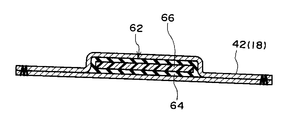
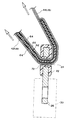
- FIG. 3 is a cross-sectional view of the webbing along the line AA in FIG. 2. It is sectional drawing of the tongue in the mounting state of webbing, and its vicinity.
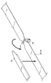
- It is a disassembled perspective view of webbing which shows the state before providing a dilatant characteristic part in webbing.
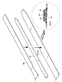
- It is a disassembled perspective view of the webbing which shows the modification of the state before providing a dilatant characteristic part in webbing.
- It is a disassembled perspective view of the webbing which shows the modification of the state before providing a dilatant characteristic part in webbing.
- It is a disassembled perspective view of the webbing which shows the modification of the state before providing a dilatant characteristic part in webbing.
- It is a disassembled perspective view of the webbing which shows the modification
- FIG. 1 shows a schematic front view of the overall configuration of a seat belt device 10 according to the present embodiment.
- the seat belt device 10 includes a retractor 12.
- the retractor 12 is fixed to the vehicle body, the frame 16 of the seat 14 and the like (vehicle body not shown in the present embodiment) on the side in the width direction of the seat 14 installed in the vehicle.
- a spool having an axial direction along the longitudinal direction of the vehicle is rotatably provided on the retractor 12, and a longitudinal base end portion of a webbing 18 formed in a long band shape is locked to the spool. Yes.
- the webbing 18 is stored in a state in which the base end side in the longitudinal direction is wound in a layered manner on the outer peripheral portion of the spool, and the tip end side thereof is pulled out upward of the vehicle. Further, the retractor 12 is provided with a lock mechanism (not shown) so that the spool is locked when the vehicle is suddenly decelerated and the rotation of the spool when the webbing 18 is pulled out of the spool is regulated. It has become.
- a shoulder anchor 20 is attached to the vehicle body above the retractor 12.
- the shoulder anchor 20 is formed with a slit hole penetrating generally in the width direction of the vehicle, and the webbing 18 drawn upward from the spool of the retractor 12 passes through the slit hole of the shoulder anchor 20 and is folded downward. .
- a tongue 22 is provided on the webbing 18 on the front end side of the shoulder anchor 20 in the webbing 18. As shown in FIGS. 2 and 4, the tongue 22 is formed by covering a part of the core metal with a synthetic resin material with a metal plate material. The tongue 22 is formed with a passage hole 24 penetrating in the thickness direction. The longitudinal direction of the passage hole 24 is a slit shape along the width direction of the webbing 18, and the webbing 18 passes through the passage hole 24.
- the protruding portion from the synthetic resin material in the core of the tongue 22 is an insertion portion 26.
- the insertion portion 26 of the tongue 22 is inserted into the buckle 30 provided in The insertion part 26 is held by the buckle 30.
- a portion of the webbing 18 on the front end side than the passage hole 24 of the tongue 22 is used as a lap webbing 42 to restrain the waist portion of the occupant 28, and a portion of the webbing 18 on the proximal end side of the passage hole 24 of the tongue 22.
- the shoulder webbing 44 restrains the abdomen, chest and shoulders of the occupant 28.
- an anchor plate 52 is attached to the vehicle body, the frame 16 of the seat 14 or the like (a vehicle body not shown in the present embodiment) on the side of the seat 14 where the retractor 12 is provided.
- a slit hole 54 is formed in the anchor plate 52.
- the webbing 18 passes through the slit hole 54 and is folded back to the base end side in the longitudinal direction of the webbing 18 up to a portion that becomes the shoulder webbing 44 of the webbing 18. And are superimposed.
- a dilatant characteristic portion 62 is provided between the webbing 18 thus superposed.
- the dilatant characteristic portion 62 is a state where the occupant 28 inserts the insertion portion 26 of the tongue 22 into the buckle 30 and wears the webbing 18 on the body, and the webbing 18 side of the wrap webbing 42 through the passage hole 24 of the tongue 22. To the shoulder webbing 44 side.
- the dilatant characteristic portion 62 is folded back at the slit hole 54 in a state where it is placed on the base end side (or the distal end side) of the webbing 18 relative to the folding position at the slit hole 54.
- the dilatant characteristic part 62 is built in the webbing 18 by covering the front end side (or the base end side) of the position and stitching the webbing 18 so as to surround the dilatant characteristic part 62 from the outside.
- the dilatant characteristic portion 62 includes a covering portion 64.
- the covering portion 64 is formed of, for example, a rubber material or a flexible synthetic resin material having elasticity similar to that of a rubber material.
- the covering portion 64 is formed in a hollow shape whose longitudinal direction is along the longitudinal direction of the webbing 18.
- a portion from the predetermined position (longitudinal intermediate portion) on one end side in the longitudinal direction of the covering portion 64 to the one end portion is formed in a tapered shape in which the width dimension gradually decreases toward the one end side.
- a portion from the predetermined position (longitudinal intermediate portion) on the other end side in the longitudinal direction of the covering portion 64 to the other end portion is formed in a tapered shape in which the width dimension gradually decreases toward the other end side.
- a dilatant characteristic resin 66 as a dilatant characteristic material is provided inside the covering portion 64.
- the dilatant characteristic resin 66 is in a liquid state or a gel state in a normal state, but has a characteristic of being instantaneously cured when an external load is applied.
- the setting range of the dilatant characteristic portion 62 in the webbing 18 is such that a part of the dilatant characteristic portion 62 is within the passage hole 24 as shown in FIG. 4 when the webbing 18 is attached to the body of the occupant 28 shown in FIG. Is set to be located. Further, in the present embodiment, one end of the dilatant characteristic portion 62 (the end portion on the anchor plate 52 side) is sufficiently separated from the passage hole 24 in a state where the webbing 18 is attached to the body of the occupant 28, and the lap webbing 42. The dilatant characteristic part 62 is set in most of the above.
- the other end of the dilatant characteristic portion 62 (the end portion on the shoulder anchor 20 side) is positioned in the vicinity of the passage hole 24 in a state where the webbing 18 is attached to the body of the occupant 28.
- the range of the dilatant characteristic portion 62 is set.
- the setting range of the dilatant characteristic portion 62 described above is merely an example, and one end of the dilatant characteristic portion 62 may be positioned in the vicinity of the passage hole 24 when the webbing 18 is attached to the body of the occupant 28. You may set the other end of the dilatant characteristic part 62 so that the dilatant characteristic part 62 may be located in the webbing 44 most.
- the thickness of the webbing 18 is increased by the amount provided with the dilatant characteristic portion 62, and the cross-sectional shape of the webbing 18 is one in the thickness direction (the dilatant characteristic portion 62 is provided.
- the arrangement portion of the dilatant characteristic portion 62 swells toward the side).
- both ends in the longitudinal direction of the covering portion 64 are formed in a tapered shape in which the width dimension is gradually shortened, the bulge in the arrangement portion of the dilatant characteristic portion 62 is also gradually increased on both ends in the longitudinal direction.
- the taper has a shorter dimension.
- the swelling of the webbing 18 due to the provision of the dilatant characteristic portion 62 is located on the lap webbing 42 side on the body side of the occupant 28 and on the shoulder webbing 44 side on the side opposite to the occupant 28 body. To position.
- a notch 72 is formed in the tongue 22 corresponding to the cross-sectional shape of the webbing 18 at the position where the dilatant characteristic portion 62 is provided.
- the notch 72 is a substantially rectangular notch opened at the inner peripheral portion of the passage hole 24, and the bulging portion of the webbing 18 by providing the dilatant characteristic portion 62 passes through the inside of the notch 72.
- the occupant 28 seated on the seat 14 wears the webbing 18, first, the occupant 28 grasps the tongue 22 and pulls the webbing 18 toward the buckle 30. As a result, the webbing 18 wound on the spool of the retractor 12 is pulled out. The pulled-out webbing 18 is hung around the front of the occupant 28 at the portion between the anchor plate 52 and the shoulder anchor 20. In this state, the insertion portion 26 of the tongue 22 is inserted into the buckle 30 and the tongue 22 is held by the buckle 30, whereby the webbing 18 is attached to the body of the occupant 28.
- the webbing 18 passes through the passage hole 24 formed in the tongue 22, but when the occupant 28 grips the tongue 22 and pulls the webbing 18, the portion where the dilatant characteristic portion 62 is provided in the webbing 18 is the tongue. 22 is reached.
- the widthwise intermediate portion of the webbing 18 on one side in the thickness direction of the webbing 18 is thicker than other portions of the webbing 18.
- the notch 72 is formed in the tongue 22 corresponding to the portion where the thickness is increased by providing the dilatant characteristic portion 62 in the webbing 18 as described above. A portion having an increased thickness of 18 passes through the notch 72. For this reason, the webbing 18 can pass through the tongue 22 even if the thickness of the webbing 18 is partially increased by providing the dilatant characteristic portion 62 on the webbing 18.
- both ends in the longitudinal direction of the dilatant characteristic portion 62 are formed in a tapered shape in which the width dimension gradually decreases toward the outer side in the width direction (toward both ends in the width direction), the dilatant characteristic portion 62 is formed in the webbing 18.
- the portion where the thickness is increased by the provision also has a tapered shape in which the width dimension gradually decreases in the vicinity of both ends in the longitudinal direction. For this reason, when the portion where the dilatant characteristic portion 62 is provided in the webbing 18 enters the notch 72, both ends in the width direction of the portion where the thickness is increased in the webbing 18 are positioned inside the both ends in the width direction of the notch 72.
- both ends in the longitudinal direction of the dilatant characteristic portion 62 are tapered as described above, but only one of the one end side and the other end side in the longitudinal direction of the dilatant characteristic portion 62 is tapered. It is good also as a structure to form.
- the dilatant characteristic portion 62 is formed in a tapered shape in which the width dimension is gradually shortened at one end side and the other end side in the longitudinal direction. In addition to such a configuration, for example, the dilatant characteristic portion 62 is configured so that the dilatant characteristic portion 62 gradually becomes thinner toward the end side than the middle portion in the longitudinal direction of the dilatant characteristic portion 62, and thereby the webbing 18.
- the portion where the thickness is increased by providing the dilatant characteristic portion 62 may be configured such that the increase in the thickness dimension is minimized at the end portion side. Even in such a configuration, the longitudinal end portion of the webbing 18 where the thickness is increased can smoothly enter the cutout 72 without passing through the cutout 72 and pass through the cutout 72.
- the front end side (anchor plate 52 side) of the webbing 18 from the portion located inside the passage hole 24 of the tongue 22 is the lap webbing 42, and the waist of the occupant 28 is moved from the front of the vehicle. to bound.
- a portion of the webbing 18 located between the inner side of the passage hole 24 of the tongue 22 and the shoulder anchor 20 is a shoulder buckle 30 on the shoulder 28 on the shoulder anchor 20 side in the body of the occupant 28.
- the shoulder webbing 44 restrains the space up to the side from the front of the vehicle. In this way, the body of the occupant 28 seated on the seat 14 is restrained by the webbing 18.
- the webbing 18 has a tensile force toward the distal end side in the longitudinal direction (anchor plate 52 side) and a longitudinal proximal end side (the shoulder anchor 20 side) with the portion located inside the passage hole 24 (the tongue 22) as a boundary. The pulling force to act. A portion of the webbing 18 located in the passage hole 24 of the tongue 22 is pressed against the inner peripheral portion of the passage hole 24 by the webbing 18 being pulled as described above.
- the dilatant characteristic portion 62 is continuously provided from the lap webbing 42 side to the shoulder webbing 44 side when the webbing 18 is mounted. For this reason, when the part located in the passage hole 24 of the webbing 18 is pressed against the inner peripheral part of the passage hole 24, the dilatant characteristic part 62 in the webbing 18 has a pressing reaction force from the inner peripheral part of the passage hole 24, That is, it receives a load.
- the dilatant characteristic resin 66 constituting the dilatant characteristic portion 62 the portion located in the passage hole 24 and the vicinity thereof are subjected to the above-described load so that the side opposite to the insertion portion 26 of the tongue 22 is in the thickness direction. It is instantly cured into a substantially U-shape that is sandwiched from both sides.
- the tongue 22 is not configured to lock the webbing 18 when the webbing 18 is pulled by the body of the occupant 28, and the webbing 18 receives a load from the inner peripheral portion of the passage hole 24.
- the cured dilatant characteristic resin 66 receives this load. For this reason, it is difficult for an excessive load to act on the webbing 18, and damage to the webbing 18 can be prevented.
- the dilatant characteristic portion 62 is liquid or gel-like when no load is applied, the dilatant characteristic portion 62 is deformed so as to follow the bending of the webbing 18. Therefore, in a state where no load is applied to the dilatant characteristic resin 66, the dilatant characteristic portion 62 is deformed following the bending of the webbing 18 when passing through the passage hole 24 of the tongue 22, and the webbing 18 passes through the tongue 22. It passes through the hole 24 relatively smoothly. Thereby, even if the dilatant characteristic part 62 is provided, mounting
- the dilatant characteristic portion 62 has a configuration in which a dilatant characteristic resin 66 is provided inside the covering portion 64. Therefore, the hardness of the dilatant characteristic resin 66 can be made difficult to be transmitted to the occupant 28 when the cured dilatant characteristic resin 66 is pressed on the waist of the occupant 28 who is about to move inertially forward of the vehicle.
- the lap webbing 42 is increased in thickness by the amount provided with the dilatant characteristic portion 62. As described above, since the thickness of the lap webbing 42 is increased, it is possible to prevent the so-called “slack” from being slackened to the lap webbing 42 in a state where the occupant 28 wears the webbing 18. The inertial movement of the waist of the occupant 28 to the side can be prevented or suppressed.
- the dilatant characteristic portion 62 is positioned so that the other end of the dilatant characteristic portion 62 (the end portion on the shoulder anchor 20 side) is positioned in the vicinity of the passage hole 24 when the webbing 18 is attached to the body of the occupant 28.
- the range is set. For this reason, most of the shoulder webbing 44 does not bulge or the like due to the provision of the dilatant characteristic portion 62, and has a simple band shape. Thereby, when the occupant 28 wears the webbing 18, the occupant 28 feels better and looks good.
- the dilatant characteristic portion 62 does not protrude greatly toward the shoulder webbing 44, so that the dilatant characteristic portion 62 is not unnecessarily lengthened and the cost is reduced.
- the webbing 18 has a dilatant characteristic portion 62 sandwiched between the proximal end side and the distal end side of the webbing 18 at the slit hole 54.
- the dilatant characteristic portion 62 was provided in the webbing 18 by sewing around the dilatant characteristic portion 62.
- the configuration in which the dilatant characteristic portion 62 is provided on the webbing 18 is not limited to such an aspect.
- FIGS. 6 to 8 show exploded perspective views of the embodiment, but the cross-sectional view in the assembled state (the state in which the dilatant characteristic portion 62 is provided on the webbing 18) is shown by a one-dot chain line circle in each drawing. Shown in.
- the webbing 18 is formed in a bag shape opened at the tip (portion locked to the anchor plate 52) in a range where at least the dilatant characteristic portion 62 of the webbing 18 is disposed.
- the dilatant characteristic part 62 may be provided in the webbing 18 by inserting the dilatant characteristic part 62 into the webbing 18 from the tip of the webbing 18 and stitching the periphery of the dilatant characteristic part 62 in the webbing 18.
- the dilatant characteristic portion 62 may be provided on the webbing 18 by stitching the periphery of the dilatant characteristic portion 62 in the sheet material 82.
- the dilatant characteristic portion 62 is disposed on one surface in the thickness direction of the webbing 18, and then the dilatant characteristic portion 62 and the webbing 18 are stitched to attach the dilatant characteristic portion 62 to the webbing 18.
- the dilatant characteristic portion 62 may be integrally attached, or an adhesive may be applied to the surface of the dilatant characteristic portion 62 facing the webbing 18, and the dilatant characteristic portion 62 may be integrally fixed to the webbing 18 with this adhesive.
Abstract
Provided is a seat belt device wherein movement of a webbing from the shoulder side toward the lap side can be prevented or restrained when the webbing is pulled, without particularly increasing the strength of the webbing. A dilatant characteristic part (62) configured so as to include a dilatant characteristic resin member (66) is provided in a webbing (18) from a lap webbing (42) portion to a portion that extends further to the shoulder webbing (44) side than the through-hole (24) of a tongue (22) in a webbing-attached state. When the webbing (18) is pressed against an inner peripheral part of the through-hole (24) due to a vehicle occupant's body pulling the webbing (18) when the vehicle rapidly decelerates, the dilatant characteristic resin member (66) is hardened by the load. The flexure of the webbing (18) when the webbing (18) attempts to move through the through-hole (24) is thereby restricted, and the shoulder webbing (44) can therefore be prevented or restrained from moving through the through-hole (24) to the waist of the vehicle occupant.
Description
本発明は、ウェビン0グによりシートに着座した乗員の身体を拘束するシートベルト装置に関する。
The present invention relates to a seat belt device for restraining the body of an occupant seated on a seat with a webin.
下記特許文献1に開示されたシートベルト装置は、乗員がウェビングを装着するとバックル駆動装置が作動してバックル装置をシートの幅方向外側へ移動させる。これにより、ウェビングのうちタングよりも長手方向基端側で乗員の胸部や肩部を拘束するショルダウェビングにおけるスラックを少なくしている。
特開2007-196881号の公報
In the seat belt device disclosed in Patent Document 1 below, when the occupant wears the webbing, the buckle driving device operates to move the buckle device outward in the width direction of the seat. This reduces slack in shoulder webbing that restrains the chest and shoulders of the occupant on the proximal side in the longitudinal direction from the tongue of the webbing.
Japanese Laid-Open Patent Publication No. 2007-196881
ところで、車両が急減速すると、乗員の身体が車両前方側へ慣性移動しようとし、これにより、ウェビングが乗員の身体により引っ張られる。これにより、ショルダウェビングがタングの通過孔を通過してラップ(腰部)側へ移動すると、乗員の腰部が車両前方へ慣性移動すると共に、ショルダウェビングの張力、特に、ショルダウェビングにおけるタング近傍部分の張力が増加する。そこで、ウェビングが乗員の身体により引っ張られた場合には、タングにおいてウェビングをロックして、ショルダウェビングがラップ側へ移動することを防止することが考えられている。
By the way, when the vehicle suddenly decelerates, the occupant's body attempts to move inertially toward the front side of the vehicle, whereby the webbing is pulled by the occupant's body. As a result, when the shoulder webbing passes through the tongue passage hole and moves toward the lap (waist) side, the occupant's waist moves inertially forward of the vehicle, and the tension of the shoulder webbing, particularly the tension in the vicinity of the tongue in the shoulder webbing Will increase. Therefore, it is considered that when the webbing is pulled by the occupant's body, the webbing is locked at the tongue to prevent the shoulder webbing from moving to the lap side.
しかしながら、タングによってウェビングをロックした状態で乗員の身体がウェビングを引っ張ると、ウェビングにおいてタングにロックされた部分に大きな荷重が集中する。このため、このような荷重に耐えられるようにウェビングの強度を高めなくてはならない。
However, when the occupant's body pulls the webbing while the webbing is locked by the tongue, a large load is concentrated on the portion of the webbing that is locked to the tongue. For this reason, the strength of the webbing must be increased to withstand such a load.
本発明は、上記事実を考慮して、ウェビングの強度を特に高めることなく、ウェビングが引っ張られた際にショルダ側からラップ側へのウェビングの移動を防止又は抑制できるシートベルト装置を得ることが目的である。
In view of the above facts, an object of the present invention is to provide a seat belt device that can prevent or suppress the movement of the webbing from the shoulder side to the lap side when the webbing is pulled without particularly increasing the strength of the webbing. It is.
請求項1に記載の本発明に係るシートベルト装置は、長手方向中間部がタングに形成された通過孔を通過して、前記タングが前記長手方向に移動可能に設けられ、乗員の身体に対する装着状態では前記通過孔よりも長手方向一端側で前記乗員の腰部を拘束するラップウェビングとなり、前記通過孔よりも長手方向他端側で前記乗員の胸部や肩部を拘束するショルダウェビングとなるウェビングと、前記装着状態で前記ウェビングにおける前記通過孔の内側に位置する部分を含む領域に設けられ、所定の大きさ以上の荷重が作用することで硬化するダイラタント特性を有する材料を含んで構成されたダイラタント特性部と、を備えている。
The seat belt device according to the first aspect of the present invention has a longitudinal intermediate portion that passes through a passage hole formed in the tongue, and the tongue is movably provided in the longitudinal direction. In the state, a lap webbing that restrains the occupant's waist at one end in the longitudinal direction from the passage hole, and a webbing that becomes a shoulder webbing that restrains the chest and shoulders of the occupant at the other end in the longitudinal direction from the passage hole A dilatant comprising a material having a dilatant characteristic that is provided in a region including a portion of the webbing located inside the passage hole in the mounted state and hardens when a load of a predetermined size or more acts. And a characteristic part.
請求項1に記載の本発明に係るシートベルト装置では、乗員の身体にウェビングが掛け回され、この状態でウェビングに設けられたタングがバックルに挿入されると乗員の身体に対するウェビングの装着状態になる。この装着状態では、ウェビングのうち、タングの通過孔よりも長手方向一端側はラップウェビングとなって乗員の腰部を拘束し、タングの通過孔よりも長手方向他端側はショルダウェビングとなって乗員の胸部や肩部を拘束する。
In the seat belt device according to the first aspect of the present invention, when the webbing is wound around the occupant's body and the tongue provided on the webbing is inserted into the buckle in this state, the webbing is attached to the occupant's body. Become. In this wearing state, one end of the webbing in the longitudinal direction from the tongue passage hole becomes a lap webbing to restrain the waist of the occupant, and the other end in the longitudinal direction from the tongue passage hole becomes a shoulder webbing to occupant Restrain the chest and shoulders.
一方、本発明に係るシートベルト装置では、ウェビングにダイラタント特性部が設けられる。上記の装着状態ではウェビングにおいてタングに形成された通過孔の内側に位置する部分を含む領域にダイラタント特性部が位置する。例えば、車両が急減速することにより乗員の身体が車両前方側へ慣性移動しようとすると、ラップウェビングは乗員の腰部によりその長手方向一端側(すなわち、タングとは反対側)へ引っ張られ、ショルダウェビングは乗員の胸部等によりその長手方向他端側(すなわち、タングとは反対側)へ引っ張られる。
On the other hand, in the seat belt device according to the present invention, the dilatant characteristic portion is provided in the webbing. In the above mounted state, the dilatant characteristic portion is located in a region including a portion located inside the through hole formed in the tongue in the webbing. For example, when the vehicle body suddenly decelerates and the occupant's body tries to move to the front side of the vehicle, the lap webbing is pulled by the occupant's waist to one end in the longitudinal direction (that is, opposite to the tongue), and the shoulder webbing Is pulled toward the other end in the longitudinal direction (that is, opposite to the tongue) by the occupant's chest or the like.
このようにウェビングが引っ張られることで、ウェビングにおいてタングの通過孔の内側に位置する部分は通過孔の内周部に押し付けられ、通過孔の内周部からの押圧反力を受ける。ウェビングに設けられたダイラタント特性部は所定の大きさ以上の荷重が作用することで硬化するダイラタント特性を有する材料を含んで構成されているので、通過孔の内周部からの押圧反力をダイラタント特性部が受けるとダイラタント特性部が硬化する。これにより、少なくともウェビングにおける通過孔の内側に位置している部分とその近傍は、硬化したダイラタント特性部により撓曲が規制され、ショルダウェビングがタングの通過孔を通過して乗員の腰部側へ移動することを防止又は抑制できる。
As the webbing is pulled in this way, the portion of the webbing located inside the passage hole of the tongue is pressed against the inner periphery of the passage hole, and receives a pressing reaction force from the inner periphery of the passage hole. The dilatant characteristic part provided on the webbing is composed of a material having a dilatant characteristic that hardens when a load of a predetermined size or more is applied, so that the pressing reaction force from the inner peripheral part of the passage hole is dilatanted. When the characteristic part receives, the dilatant characteristic part hardens. As a result, at least the portion of the webbing that is located inside the passage hole and its vicinity are restricted from bending by the hardened dilatant characteristic part, and the shoulder webbing passes through the tongue passage hole and moves toward the occupant's waist. Can be prevented or suppressed.
しかも、上記のようにウェビングが引っ張られた場合には、タングの通過孔を通過している部分とその近傍が硬化したダイラタント特性部によってウェビングが支持されるので、ウェビング自体の強度を特に高めなくても、通過孔の内周部からの押圧反力(すなわち、荷重)にウェビングは耐えることができる。
In addition, when the webbing is pulled as described above, the webbing is supported by the portion of the tongue passing through the through hole and the dilatant characteristic part cured in the vicinity thereof, so that the strength of the webbing itself is not particularly increased. However, the webbing can withstand the pressing reaction force (that is, load) from the inner periphery of the passage hole.
請求項2に記載の本発明に係るシートベルト装置は、請求項1に記載の本発明において、前記乗員の身体に前記ウェビングが装着された状態で前記通過孔よりも前記ラップウェビング側の領域まで前記ダイラタント特性部を設けている。
A seat belt device according to a second aspect of the present invention is the seat belt device according to the first aspect of the present invention, wherein the webbing is mounted on the occupant's body up to a region closer to the lap webbing than the passage hole. The dilatant characteristic portion is provided.
請求項2に記載の本発明に係るシートベルト装置では、乗員の身体にウェビングが装着された状態では、タングの通過孔よりもラップウェビング側までダイラタント特性部が位置する。このため、ラップウェビングではダイラタント特性部を設けた分だけ厚みが増す。このように、ラップウェビングの厚みが増すことで、乗員がウェビングを装着した状態におけるラップウェビングの弛み、所謂「スラック」を軽減できる。
In the seat belt device according to the second aspect of the present invention, when the webbing is mounted on the occupant's body, the dilatant characteristic portion is located from the tongue passage hole to the lap webbing side. For this reason, the thickness of the lap webbing is increased by the amount provided with the dilatant characteristic portion. In this way, by increasing the thickness of the lap webbing, it is possible to reduce so-called “slack” of the lap webbing when the occupant wears the webbing.
請求項3に記載の本発明に係るシートベルト装置は、請求項1に記載の本発明において、前記乗員の身体に前記ウェビングが装着された状態で前記通過孔よりも前記ショルダウェビング側へ通過した領域で且つ前記通過孔の近傍部分まで前記ダイラタント特性部を設けている。
The seatbelt device according to a third aspect of the present invention is the seatbelt device according to the first aspect of the present invention, in which the webbing is passed to the shoulder webbing side from the passage hole in a state where the webbing is attached to the body of the occupant. The dilatant characteristic part is provided in a region and in the vicinity of the passage hole.
請求項3に記載の本発明に係るシートベルト装置では、乗員の身体にウェビングが装着された状態では、タングの通過孔よりもショルダウェビング側における通過孔の近傍までダイラタント特性部が位置する。このため、ショルダウェビングの大部分にはダイラタント特性部が設けられないので、ショルダウェビングの大部分はダイラタント特性部を設けることによる膨らみ等が生じず、単なる帯状となる。これにより、乗員がウェビングを装着した際に乗員が感じる装着感が向上すると共に見栄えもよい。
In the seatbelt device according to the third aspect of the present invention, in a state where the webbing is mounted on the occupant's body, the dilatant characteristic portion is located closer to the passage hole on the shoulder webbing side than the passage hole of the tongue. For this reason, most of the shoulder webbing is not provided with the dilatant characteristic part, so that the majority of the shoulder webbing does not swell due to the provision of the dilatant characteristic part, and has a simple band shape. Thereby, when a passenger | crew mount | wears webbing, the installation feeling which a passenger | crew feels improves and it is good looking.
しかも、乗員の身体にウェビングが装着された状態では、ダイラタント特性部がショルダウェビング側へ大きくはみ出ないので、コストも安価になる。
Moreover, when the webbing is mounted on the occupant's body, the dilatant characteristic portion does not protrude greatly toward the shoulder webbing side, so the cost is also low.
請求項4に記載の本発明に係るシートベルト装置は、請求項1から請求項3の何れか1項に記載の本発明において、前記ウェビングの一端側で前記ウェビングを折り返して、この折り返し位置よりも前記ウェビングの他端側と前記折り返し位置よりも前記ウェビングの一端側との間に前記ダイラタント特性部を配置した状態で、前記折り返し位置よりも前記ウェビングの他端側と前記折り返し位置よりも前記ウェビングの一端側とを重ね、前記ウェビングにおける前記ダイラタント特性部の周囲を縫合している。
A seat belt device according to a fourth aspect of the present invention is the seat belt device according to any one of the first to third aspects, wherein the webbing is folded back at one end side of the webbing, In the state where the dilatant characteristic portion is disposed between the other end side of the webbing and one end side of the webbing with respect to the folding position, the other end side of the webbing and the folding position than the folding position. One end side of the webbing is overlapped and the periphery of the dilatant characteristic portion in the webbing is stitched.
請求項4に記載の本発明に係るシートベルト装置では、ウェビングの一端側でウェビングが折り返され、この折り返し位置よりもウェビングの他端側と、この折り返し位置よりもウェビングの一端側と、の間にダイラタント特性部が配置される。この状態で、上記の折り返し位置よりもウェビングの他端側と一端側とが重ねられ、ダイラタント特性部の周囲で重ねられたウェビングの一端側と他端側とが縫合される。これにより、ウェビングにダイラタント特性部が設けられる。
In the seat belt device according to the fourth aspect of the present invention, the webbing is folded at one end side of the webbing, and between the other end side of the webbing from the folded position and the one end side of the webbing from the folded position. The dilatant characteristic portion is disposed in In this state, the other end side and one end side of the webbing are overlapped with respect to the folding position, and the one end side and the other end side of the webbing overlapped around the dilatant characteristic portion are stitched. Thereby, a dilatant characteristic part is provided in webbing.
請求項5に記載の本発明に係るシートベルト装置は、請求項1から請求項3の何れか1項に記載の本発明において、前記ウェビングをその一端にて開口した袋状に形成すると共に、この開口から前記ダイラタント特性部を前記ウェビングの内側に挿入した状態で、前記ダイラタント特性部よりも前記ウェビングの一端側を縫合している。
A seatbelt device according to a fifth aspect of the present invention is the seatbelt apparatus according to any one of the first to third aspects, wherein the webbing is formed in a bag shape opened at one end thereof, and In a state where the dilatant characteristic portion is inserted into the webbing from the opening, one end side of the webbing is stitched from the dilatant characteristic portion.
請求項5に記載の本発明に係るシートベルト装置によれば、ウェビングはその一端が開口した袋状に形成され、ダイラタント特性部はこの開口からウェビングの内側に挿入される。ウェビングの内側にダイラタント特性部が収容された状態でウェビングの一端における開口を閉じるようにウェビングが縫合される。これにより、ウェビングにダイラタント特性部が設けられる。
According to the seat belt device of the present invention as set forth in claim 5, the webbing is formed in a bag shape having one end opened, and the dilatant characteristic portion is inserted into the webbing from the opening. The webbing is sewn so as to close the opening at one end of the webbing while the dilatant characteristic portion is accommodated inside the webbing. Thereby, a dilatant characteristic part is provided in webbing.
請求項6に記載の本発明に係るシートベルト装置は、請求項1から請求項3の何れか1項に記載の本発明において、前記ウェビングを厚さ方向一方の面に前記ダイラタント特性部を一体的に取り付けている。
A seatbelt device according to a sixth aspect of the present invention is the seatbelt device according to any one of the first to third aspects, wherein the webbing is integrated with the dilatant characteristic portion on one surface in the thickness direction. Attached.
請求項7に記載の本発明に係るシートベルト装置によれば、ウェビングの厚さ方向一方の面に縫合や接着等によりダイラタント特性部が一体的に取り付けられる。これにより、ウェビングにダイラタント特性部が設けられる。
According to the seat belt device of the present invention as set forth in claim 7, the dilatant characteristic portion is integrally attached to one surface in the thickness direction of the webbing by stitching or adhesion. Thereby, a dilatant characteristic part is provided in webbing.
請求項7に記載の本発明に係るシートベルト装置は、請求項1から請求項6の何れか1項に記載の本発明において、前記ウェビングの幅方向に沿った前記ダイラタント特性部の幅寸法を前記ウェビングの幅寸法よりも短く設定して前記ウェビングの厚さ方向一方の側に前記ダイラタント特性部を設けると共に、前記ダイラタント特性部が内側を通過する切欠部を前記通過孔に連通するように前記タングに形成している。
A seat belt device according to a seventh aspect of the present invention is the seat belt device according to any one of the first to sixth aspects, wherein the width of the dilatant characteristic portion along the width direction of the webbing is determined. The dilatant characteristic part is provided on one side in the thickness direction of the webbing by setting it shorter than the width dimension of the webbing, and the notch part through which the dilatant characteristic part passes is connected to the passage hole. It is formed into a tongue.
請求項7に記載の本発明に係るシートベルト装置によれば、ダイラタント特性部の幅方向はウェビングの幅方向に沿っており、しかも、その幅寸法はウェビングの幅寸法よりも短く設定され、ウェビングの厚さ方向一方の側にダイラタント特性部が設けられる。
According to the seat belt device of the present invention as set forth in claim 7, the width direction of the dilatant characteristic portion is along the width direction of the webbing, and the width dimension is set shorter than the width dimension of the webbing. A dilatant characteristic portion is provided on one side in the thickness direction.
一方、タングにはウェビングが通過する通過孔が形成されるが、更に、タングには切欠部が通過孔に連通するように形成され、ウェビングが通過孔を通過する際には、この切欠部をダイラタント特性部が通過する。このように、ウェビングの厚さ方向一方の側にダイラタント特性部を設けることでダイラタント特性部を含んだウェビング全体の厚さが増しても、ダイラタント特性部が上記の切欠部を通過することでウェビングは比較的円滑にショルダウェビング側からラップウェビング側へ、又は、ラップウェビング側からショルダウェビング側へ移動できる。
On the other hand, a passage hole through which the webbing passes is formed in the tongue, and further, a notch is formed in the tongue so as to communicate with the passage hole, and when the webbing passes through the passage hole, this notch is formed. The dilatant characteristic part passes. Thus, even if the thickness of the entire webbing including the dilatant characteristic part is increased by providing the dilatant characteristic part on one side in the thickness direction of the webbing, the webbing is caused by the dilatant characteristic part passing through the notch part. Can move relatively smoothly from the shoulder webbing side to the lap webbing side or from the lap webbing side to the shoulder webbing side.
請求項8に記載の本発明に係るシートベルト装置は、請求項1から請求項7の何れか1項に記載の本発明において、荷重を受けることにより硬化するダイラタント特性を有するダイラタント材料を、硬化状態の前記ダイラタント特性部本体よりも柔軟な被覆部で被覆することにより前記ダイラタント特性部を形成している。
The seatbelt device according to the present invention as set forth in claim 8 is a hardened dilatant material having a dilatant characteristic that is cured by receiving a load in the present invention according to any one of claims 1 to 7. The dilatant characteristic portion is formed by covering with a covering portion that is more flexible than the dilatant characteristic portion main body in the state.
請求項8に記載の本発明に係るシートベルト装置によれば、ダイラタント特性を有するダイラタント材料が、硬化したダイラタント材料よりも柔軟な被覆部により被覆される。このため、荷重を受けてダイラタント材料が硬化しても、この硬化したダイラタント材料と乗員の身体との間に柔軟な被覆部が介在するので、乗員の身体に対して硬化したダイラタント材料の硬さが伝わり難くなる。
According to the seat belt device of the present invention as set forth in claim 8, the dilatant material having the dilatant characteristic is covered with a covering portion that is more flexible than the cured dilatant material. For this reason, even if the dilatant material is cured by receiving a load, since the flexible covering portion is interposed between the cured dilatant material and the occupant's body, the hardness of the dilatant material cured against the occupant's body Is difficult to communicate.
請求項9に記載の本発明に係るシートベルト装置は、請求項1から請求項8の何れか1項に記載の本発明において、前記ウェビングの長手方向に沿った前記ダイラタント特性部の中間部から一端及び他端の少なくとも一方へ向けて前記ウェビングの幅方向に沿った前記ダイラタント特性部の幅寸法が漸次短くなるテーパ状に形成し、前記ウェビングにおいて前記ダイラタント特性部を設けることにより厚さ寸法が増した部分が通過する切欠部を前記通過孔に連通するように前記タングに形成している。
A seat belt device according to a ninth aspect of the present invention is the seat belt device according to any one of the first to eighth aspects of the present invention, wherein the seat belt device includes an intermediate portion of the dilatant characteristic portion along the longitudinal direction of the webbing. By forming the dilatant characteristic part in a taper shape in which the width dimension of the dilatant characteristic part along the width direction of the webbing is gradually shortened toward at least one of the one end and the other end, the thickness dimension is provided by providing the dilatant characteristic part in the webbing. A notch through which the increased portion passes is formed in the tongue so as to communicate with the passage hole.
請求項9に記載の本発明に係るシートベルト装置では、ウェビングにおいてダイラタント特性部が設けられた部分では厚さ寸法が増す。このようにウェビングにおいて厚さ寸法が増した部分に対応してタングには通過孔に連通した切欠部が形成され、ウェビングにおいてダイラタント特性部を設けることで厚さ寸法が増した部分は、その一部が切欠部を通過することで比較的円滑にショルダウェビング側からラップウェビング側へ、又は、ラップウェビング側からショルダウェビング側へ移動できる。
In the seat belt device according to the ninth aspect of the present invention, the thickness dimension is increased at the portion where the dilatant characteristic portion is provided in the webbing. In this way, a notch connected to the passage hole is formed in the tongue corresponding to the portion where the thickness dimension is increased in the webbing, and the portion where the thickness dimension is increased by providing the dilatant characteristic portion in the webbing is one of them. Since the part passes through the notch, the shoulder webbing can be moved relatively smoothly from the shoulder webbing side or from the lap webbing side to the shoulder webbing side.
ここで、本発明に係るシートベルト装置では、ウェビングの長手方向に沿ったダイラタント特性部の中間部から一端及び他端の少なくとも一方へ向けてウェビングの幅方向に沿ったダイラタント特性部の幅寸法が漸次短くなるテーパ状に形成される。このため、ウェビングにおいてダイラタント特性部を設けた部分が上記の切欠部を通過する際には、ダイラタント特性部において切欠部の開口幅よりも十分に幅寸法が短い長手方向一端又は他端から通過する。
Here, in the seat belt device according to the present invention, the width dimension of the dilatant characteristic portion along the width direction of the webbing from the intermediate portion of the dilatant characteristic portion along the longitudinal direction of the webbing to at least one of the one end and the other end. It is formed in a tapered shape that becomes gradually shorter. For this reason, when the portion where the dilatant characteristic portion is provided in the webbing passes through the cutout portion, the dilatant characteristic portion passes from one end or the other end in the longitudinal direction whose width dimension is sufficiently shorter than the opening width of the cutout portion. .
これにより、ウェビングの長手方向に沿ってダイラタント特性部を設けた部分よりも外側にタングが位置した状態から、ダイラタント特性部を設けた部分の側へ向けてタングを移動させる際に、ダイラタント特性部が設けられた部分を円滑に上記の切欠部に入り込ませて通過させることができる。
As a result, when the tongue is moved from the state where the tongue is located outside the portion where the dilatant characteristic portion is provided along the longitudinal direction of the webbing toward the portion where the dilatant characteristic portion is provided, the dilatant characteristic portion is The portion provided with can be smoothly inserted into the notch and allowed to pass therethrough.
なお、「ウェビングの長手方向に沿ったダイラタント特性部の中間部」の『中間部』とはウェビングの長手方向に沿ったダイラタント特性部の両端よりも長手方向内側を意味し、ウェビングの長手方向に沿ったダイラタント特性部の中央部に限定するものではない。
The “intermediate part” of the “intermediate part of the dilatant characteristic part along the longitudinal direction of the webbing” means the inner side in the longitudinal direction from both ends of the dilatant characteristic part along the longitudinal direction of the webbing. It is not limited to the central part of the dilatant characteristic part along.
以上説明したように、請求項1に記載の本発明に係るシートベルト装置は、ウェビングにおけるタングの通過孔の内側に位置している部分とその近傍の撓曲を、硬化したダイラタント特性部により撓曲が規制でき、ショルダウェビングがタングの通過孔を通過して乗員の腰部側へ移動することを防止又は抑制できる。しかも、硬化したダイラタント特性部によってウェビングを支持されるので、ウェビング自体の強度を特に高めなくても、通過孔の内周部からの押圧反力(すなわち、荷重)にウェビングは耐えることができる。
As described above, the seatbelt device according to the first aspect of the present invention is configured such that the portion located inside the tongue passage hole in the webbing and the bending in the vicinity thereof are bent by the hardened dilatant characteristic portion. The music can be restricted, and the shoulder webbing can be prevented or suppressed from passing through the passage hole of the tongue and moving toward the occupant's waist. In addition, since the webbing is supported by the cured dilatant characteristic portion, the webbing can withstand the pressing reaction force (ie, load) from the inner peripheral portion of the passage hole without particularly increasing the strength of the webbing itself.
請求項2に記載の本発明に係るシートベルト装置は、ダイラタント特性部を設けた分だけラップウェビングの厚みが増すためラップウェビングの弛み、所謂「スラック」を軽減できる。
The seat belt device according to the second aspect of the present invention can reduce the slack of the lap webbing, so-called “slack”, because the thickness of the lap webbing is increased by the amount of the dilatant characteristic portion.
請求項3に記載の本発明に係るシートベルト装置は、乗員がウェビングを装着した際に乗員が感じる装着感が向上すると共に見栄えもよく、コストも安価になる。
The seatbelt device according to the third aspect of the present invention improves the feeling that the occupant feels when the occupant wears the webbing, has a good appearance, and is low in cost.
請求項4及び請求項5の各々に記載の本発明に係るシートベルト装置は、ウェビングの内側にダイラタント特性部を設けた状態でダイラタント特性部をウェビングに一体的に設けることができる。
In the seat belt device according to the present invention described in each of claims 4 and 5, the dilatant characteristic portion can be provided integrally with the webbing in a state where the dilatant characteristic portion is provided inside the webbing.
請求項6に記載の本発明に係るシートベルト装置は、ウェビングの厚さ方向一方の面にダイラタント特性部を一体的に設けることができる。
In the seat belt device according to the sixth aspect of the present invention, the dilatant characteristic portion can be integrally provided on one surface in the thickness direction of the webbing.
請求項7に記載の本発明に係るシートベルト装置は、ダイラタント特性部を設けることでウェビング全体の厚さが増しても、ウェビングは比較的円滑にショルダウェビング側からラップウェビング側へ、又は、ラップウェビング側からショルダウェビング側へ移動できる。
In the seat belt device according to the seventh aspect of the present invention, even if the thickness of the entire webbing is increased by providing the dilatant characteristic portion, the webbing is relatively smoothly performed from the shoulder webbing side to the lap webbing side or It can move from the webbing side to the shoulder webbing side.
請求項8に記載の本発明に係るシートベルト装置は、乗員の身体に対して硬化したダイラタント材料の硬さが伝わり難くなる。
In the seat belt device according to the present invention described in claim 8, it is difficult for the hardness of the dilatant material hardened to the occupant's body to be transmitted.
請求項9に記載の本発明に係るシートベルト装置は、ウェビングにおいてダイラタント特性部を設けた部分がタングの切欠部に入りやすくなる。
In the seat belt device according to the ninth aspect of the present invention, the portion where the dilatant characteristic portion is provided in the webbing easily enters the notch portion of the tongue.
次に本発明の一実施の形態を図1から図8の各図に基づき説明する。
Next, an embodiment of the present invention will be described with reference to FIGS.
<本実施の形態の構成>
<Configuration of this embodiment>
図1には本実施の形態に係るシートベルト装置10の全体構成が概略的な正面図により示されている。
FIG. 1 shows a schematic front view of the overall configuration of a seat belt device 10 according to the present embodiment.
この図に示されるように、本シートベルト装置10はリトラクタ12を備えている。リトラクタ12は車両に設置されたシート14の幅方向側方で車体やシート14のフレーム16等(本実施の形態では図示しない車体)に固定されている。このリトラクタ12には、例えば、軸方向が車両前後方向に沿ったスプールが回転自在に設けられており、このスプールに長尺帯状に形成されたウェビング18の長手方向基端部が係止されている。
As shown in this figure, the seat belt device 10 includes a retractor 12. The retractor 12 is fixed to the vehicle body, the frame 16 of the seat 14 and the like (vehicle body not shown in the present embodiment) on the side in the width direction of the seat 14 installed in the vehicle. For example, a spool having an axial direction along the longitudinal direction of the vehicle is rotatably provided on the retractor 12, and a longitudinal base end portion of a webbing 18 formed in a long band shape is locked to the spool. Yes.
ウェビング18はその長手方向基端側がスプールの外周部に層状に巻取られた状態で格納されており、その先端側は車両の上方引出されている。また、リトラクタ12には図示しないロック機構が設けられており、車両が急減速状態になった場合等にスプールをロックしてウェビング18がスプールから引出される際のスプールの回転を規制するようになっている。
The webbing 18 is stored in a state in which the base end side in the longitudinal direction is wound in a layered manner on the outer peripheral portion of the spool, and the tip end side thereof is pulled out upward of the vehicle. Further, the retractor 12 is provided with a lock mechanism (not shown) so that the spool is locked when the vehicle is suddenly decelerated and the rotation of the spool when the webbing 18 is pulled out of the spool is regulated. It has become.
一方、リトラクタ12の上方ではショルダアンカ20が車体に取り付けられている。ショルダアンカ20には概ね車両の幅方向に貫通したスリット孔が形成されており、リトラクタ12のスプールから上方に引出されたウェビング18はショルダアンカ20のスリット孔を通過して下方へ折り返されている。
On the other hand, a shoulder anchor 20 is attached to the vehicle body above the retractor 12. The shoulder anchor 20 is formed with a slit hole penetrating generally in the width direction of the vehicle, and the webbing 18 drawn upward from the spool of the retractor 12 passes through the slit hole of the shoulder anchor 20 and is folded downward. .
ウェビング18におけるショルダアンカ20よりも先端側ではウェビング18にタング22が設けられている。図2及び図4に示されるように、タング22は金属製の板材により芯金の一部を合成樹脂材により被覆することで形成されている。タング22にはその厚さ方向に貫通する通過孔24が形成されている。この通過孔24は長手方向がウェビング18の幅方向に沿ったスリット状とされており、この通過孔24をウェビング18が通過している。
A tongue 22 is provided on the webbing 18 on the front end side of the shoulder anchor 20 in the webbing 18. As shown in FIGS. 2 and 4, the tongue 22 is formed by covering a part of the core metal with a synthetic resin material with a metal plate material. The tongue 22 is formed with a passage hole 24 penetrating in the thickness direction. The longitudinal direction of the passage hole 24 is a slit shape along the width direction of the webbing 18, and the webbing 18 passes through the passage hole 24.
また、タング22の芯金において合成樹脂材から突出した部分は挿込部26とされている。シート14に着座した乗員28がウェビング18を装着する際には、図1に示されるように、乗員28の身体にウェビング18が掛け回された状態でシート14を介してリトラクタ12とは反対側に設けられたバックル30にタング22の挿込部26が挿し込まれる。挿込部26がバックル30に保持される。この状態では、ウェビング18においてタング22の通過孔24よりも先端側の部分がラップウェビング42とされて乗員28の腰部を拘束し、ウェビング18においてタング22の通過孔24よりも基端側の部分がショルダウェビング44とされて乗員28の腹部や胸部、肩部を拘束する。
Further, the protruding portion from the synthetic resin material in the core of the tongue 22 is an insertion portion 26. When the occupant 28 seated on the seat 14 wears the webbing 18, as shown in FIG. 1, the side opposite to the retractor 12 through the seat 14 with the webbing 18 being wound around the body of the occupant 28. The insertion portion 26 of the tongue 22 is inserted into the buckle 30 provided in The insertion part 26 is held by the buckle 30. In this state, a portion of the webbing 18 on the front end side than the passage hole 24 of the tongue 22 is used as a lap webbing 42 to restrain the waist portion of the occupant 28, and a portion of the webbing 18 on the proximal end side of the passage hole 24 of the tongue 22. The shoulder webbing 44 restrains the abdomen, chest and shoulders of the occupant 28.
さらに、シート14のリトラクタ12が設けられた側にはアンカプレート52が車体やシート14のフレーム16等(本実施の形態では図示しない車体)に取り付けられている。図2に示されるように、アンカプレート52にはスリット孔54が形成されている。ウェビング18はスリット孔54を通過して、ウェビング18のショルダウェビング44となる部分までウェビング18の長手方向基端側へ折り返されており、折り返し位置よりもウェビング18の長手方向基端側と先端側とが重ね合わされている。このように重ね合わされるウェビング18の間にはダイラタント特性部62が設けられている。ダイラタント特性部62は、乗員28がタング22の挿込部26をバックル30に挿し込んでウェビング18を身体に装着した装着状態で、タング22の通過孔24を介してウェビング18のラップウェビング42側からショルダウェビング44側へ連続するように設けられている。
Further, an anchor plate 52 is attached to the vehicle body, the frame 16 of the seat 14 or the like (a vehicle body not shown in the present embodiment) on the side of the seat 14 where the retractor 12 is provided. As shown in FIG. 2, a slit hole 54 is formed in the anchor plate 52. The webbing 18 passes through the slit hole 54 and is folded back to the base end side in the longitudinal direction of the webbing 18 up to a portion that becomes the shoulder webbing 44 of the webbing 18. And are superimposed. A dilatant characteristic portion 62 is provided between the webbing 18 thus superposed. The dilatant characteristic portion 62 is a state where the occupant 28 inserts the insertion portion 26 of the tongue 22 into the buckle 30 and wears the webbing 18 on the body, and the webbing 18 side of the wrap webbing 42 through the passage hole 24 of the tongue 22. To the shoulder webbing 44 side.
図5に示されるように、ダイラタント特性部62は、ウェビング18におけるスリット孔54での折返位置よりも基端側(又は先端側)の上に載置された状態で、スリット孔54での折返位置よりも先端側(又は基端側)が被せられ、ダイラタント特性部62を外側から囲むようにウェビング18を縫合することでウェビング18にダイラタント特性部62が内蔵されている。
As shown in FIG. 5, the dilatant characteristic portion 62 is folded back at the slit hole 54 in a state where it is placed on the base end side (or the distal end side) of the webbing 18 relative to the folding position at the slit hole 54. The dilatant characteristic part 62 is built in the webbing 18 by covering the front end side (or the base end side) of the position and stitching the webbing 18 so as to surround the dilatant characteristic part 62 from the outside.
図3に示されるように、ダイラタント特性部62は被覆部64を備えている。被覆部64は、例えば、ゴム材やゴム材程度の弾性を有する柔軟な合成樹脂材により形成されている。この被覆部64は長手方向がウェビング18の長手方向に沿った中空形状に形成されている。また、被覆部64の長手方向一端側の所定位置(長手方向中間部)から一端部までの間は一端側へ向けて漸次幅寸法が短くなるテーパ状に形成されている。さらに、被覆部64の長手方向他端側の所定位置(長手方向中間部)から他端部までの間は他端側へ向けて漸次幅寸法が短くなるテーパ状に形成されている。この被覆部64の内側にはダイラタント特性材料としてのダイラタント特性樹脂66が設けられている。ダイラタント特性樹脂66は、通常の状態では液状やゲル状であるが、外部からの荷重が加えられることで瞬時に硬化する特性を有している。
As shown in FIG. 3, the dilatant characteristic portion 62 includes a covering portion 64. The covering portion 64 is formed of, for example, a rubber material or a flexible synthetic resin material having elasticity similar to that of a rubber material. The covering portion 64 is formed in a hollow shape whose longitudinal direction is along the longitudinal direction of the webbing 18. In addition, a portion from the predetermined position (longitudinal intermediate portion) on one end side in the longitudinal direction of the covering portion 64 to the one end portion is formed in a tapered shape in which the width dimension gradually decreases toward the one end side. Further, a portion from the predetermined position (longitudinal intermediate portion) on the other end side in the longitudinal direction of the covering portion 64 to the other end portion is formed in a tapered shape in which the width dimension gradually decreases toward the other end side. A dilatant characteristic resin 66 as a dilatant characteristic material is provided inside the covering portion 64. The dilatant characteristic resin 66 is in a liquid state or a gel state in a normal state, but has a characteristic of being instantaneously cured when an external load is applied.
ウェビング18におけるダイラタント特性部62の設定範囲は、図1に示される乗員28の身体にウェビング18が装着された状態で、図4に示されるようにダイラタント特性部62の一部が通過孔24内に位置するように設定されている。また、本実施の形態では、乗員28の身体にウェビング18が装着された状態でダイラタント特性部62の一端(アンカプレート52側の端部)は通過孔24から十分に離間しておりラップウェビング42の大部分にダイラタント特性部62が設定される。これに対して、本実施の形態では、乗員28の身体にウェビング18が装着された状態でダイラタント特性部62の他端(ショルダアンカ20側の端部)は通過孔24の近傍に位置するようにダイラタント特性部62の範囲が設定されている。
The setting range of the dilatant characteristic portion 62 in the webbing 18 is such that a part of the dilatant characteristic portion 62 is within the passage hole 24 as shown in FIG. 4 when the webbing 18 is attached to the body of the occupant 28 shown in FIG. Is set to be located. Further, in the present embodiment, one end of the dilatant characteristic portion 62 (the end portion on the anchor plate 52 side) is sufficiently separated from the passage hole 24 in a state where the webbing 18 is attached to the body of the occupant 28, and the lap webbing 42. The dilatant characteristic part 62 is set in most of the above. On the other hand, in the present embodiment, the other end of the dilatant characteristic portion 62 (the end portion on the shoulder anchor 20 side) is positioned in the vicinity of the passage hole 24 in a state where the webbing 18 is attached to the body of the occupant 28. In addition, the range of the dilatant characteristic portion 62 is set.
なお、上述したダイラタント特性部62の設定範囲はあくまでも一例であり、ダイラタント特性部62の一端が乗員28の身体に対するウェビング18の装着状態で通過孔24の近傍に位置していてもよいし、ショルダウェビング44の大部分にダイラタント特性部62が位置するようにダイラタント特性部62の他端を設定してもよい。
The setting range of the dilatant characteristic portion 62 described above is merely an example, and one end of the dilatant characteristic portion 62 may be positioned in the vicinity of the passage hole 24 when the webbing 18 is attached to the body of the occupant 28. You may set the other end of the dilatant characteristic part 62 so that the dilatant characteristic part 62 may be located in the webbing 44 most.
ウェビング18においてダイラタント特性部62が設けられた範囲では、ダイラタント特性部62を設けた分だけウェビング18の厚みが増し、ウェビング18の断面形状はその厚さ方向一方(ダイラタント特性部62が設けられた側)へ向けてダイラタント特性部62の配置部分が膨らんだ凸形状になっている。しかも、上記のように、被覆部64の長手方向両端側は漸次幅寸法が短くなるテーパ状に形成されているため、ダイラタント特性部62の配置部分における膨らみも、その長手方向両端側では漸次幅寸法が短くなるテーパ状とされている。このようにダイラタント特性部62を設けることによるウェビング18の膨らみは、本実施の形態ではラップウェビング42側で乗員28の身体側に位置し、ショルダウェビング44側で乗員28の身体とは反対側に位置する。
In the range where the dilatant characteristic portion 62 is provided in the webbing 18, the thickness of the webbing 18 is increased by the amount provided with the dilatant characteristic portion 62, and the cross-sectional shape of the webbing 18 is one in the thickness direction (the dilatant characteristic portion 62 is provided. The arrangement portion of the dilatant characteristic portion 62 swells toward the side). In addition, as described above, since both ends in the longitudinal direction of the covering portion 64 are formed in a tapered shape in which the width dimension is gradually shortened, the bulge in the arrangement portion of the dilatant characteristic portion 62 is also gradually increased on both ends in the longitudinal direction. The taper has a shorter dimension. In this embodiment, the swelling of the webbing 18 due to the provision of the dilatant characteristic portion 62 is located on the lap webbing 42 side on the body side of the occupant 28 and on the shoulder webbing 44 side on the side opposite to the occupant 28 body. To position.
図2に示されるように、ダイラタント特性部62が設けられた位置でのウェビング18の断面形状に対応してタング22には切欠部72が形成されている。切欠部72は通過孔24の内周部にて開口した略矩形の切欠とされ、ウェビング18においてダイラタント特性部62を設けることで膨らんだ部分が切欠部72の内側を通過する。
As shown in FIG. 2, a notch 72 is formed in the tongue 22 corresponding to the cross-sectional shape of the webbing 18 at the position where the dilatant characteristic portion 62 is provided. The notch 72 is a substantially rectangular notch opened at the inner peripheral portion of the passage hole 24, and the bulging portion of the webbing 18 by providing the dilatant characteristic portion 62 passes through the inside of the notch 72.
<本実施の形態の作用、効果>
<Operation and effect of this embodiment>
次に、本実施の形態の作用並びに効果について説明する。
Next, the operation and effect of the present embodiment will be described.
シート14に着座した乗員28がウェビング18を装着する際には、先ず、乗員28がタング22を把持してウェビング18をバックル30側へ引っ張る。これにより、リトラクタ12のスプールに巻取られているウェビング18が引出される。引出されたウェビング18はアンカプレート52とショルダアンカ20との間の部分が乗員28の身体の前方に掛け回される。この状態でバックル30にタング22の挿込部26が挿し込まれてタング22がバックル30に保持されることで乗員28の身体に対するウェビング18の装着状態になる。
When the occupant 28 seated on the seat 14 wears the webbing 18, first, the occupant 28 grasps the tongue 22 and pulls the webbing 18 toward the buckle 30. As a result, the webbing 18 wound on the spool of the retractor 12 is pulled out. The pulled-out webbing 18 is hung around the front of the occupant 28 at the portion between the anchor plate 52 and the shoulder anchor 20. In this state, the insertion portion 26 of the tongue 22 is inserted into the buckle 30 and the tongue 22 is held by the buckle 30, whereby the webbing 18 is attached to the body of the occupant 28.
ところで、ウェビング18はタング22に形成された通過孔24を通過しているが、乗員28がタング22を把持してウェビング18を引っ張ることにより、ウェビング18においてダイラタント特性部62を設けた部分がタング22に到達する。上記のように、ウェビング18においてダイラタント特性部62を設けた部分はウェビング18の厚さ方向一方の側におけるウェビング18の幅方向中間部がウェビング18の他の部位よりも厚い。ここで、本実施の形態に係るシートベルト装置10では、このようにウェビング18においてダイラタント特性部62を設けることにより厚さが増した部分に対応してタング22に切欠部72が形成され、ウェビング18の厚さが増した部分この切欠部72を通過する。このため、ウェビング18にダイラタント特性部62を設けることで部分的にウェビング18の厚さが増してもウェビング18はタング22を通過できる。
By the way, the webbing 18 passes through the passage hole 24 formed in the tongue 22, but when the occupant 28 grips the tongue 22 and pulls the webbing 18, the portion where the dilatant characteristic portion 62 is provided in the webbing 18 is the tongue. 22 is reached. As described above, in the webbing 18 where the dilatant characteristic portion 62 is provided, the widthwise intermediate portion of the webbing 18 on one side in the thickness direction of the webbing 18 is thicker than other portions of the webbing 18. Here, in the seat belt device 10 according to the present embodiment, the notch 72 is formed in the tongue 22 corresponding to the portion where the thickness is increased by providing the dilatant characteristic portion 62 in the webbing 18 as described above. A portion having an increased thickness of 18 passes through the notch 72. For this reason, the webbing 18 can pass through the tongue 22 even if the thickness of the webbing 18 is partially increased by providing the dilatant characteristic portion 62 on the webbing 18.
しかも、ダイラタント特性部62の長手方向両端側は幅方向外側へ向けて(幅方向両端側へ向けて)漸次幅寸法が短くなるテーパ状に形成されているため、ウェビング18においてダイラタント特性部62を設けることで厚さが増した部分も、その長手方向両端部近傍では漸次幅寸法が短くなるテーパ状となる。このため、ウェビング18においてダイラタント特性部62を設けた部分が切欠部72に入り込む際、ウェビング18において厚さが増した部分の幅方向両端は切欠部72の幅方向両端よりも内側に位置する。ウェビング18において厚さが増した部分が切欠部72に入り込む際に、ウェビング18において厚さが増した部分の長手方向端部が切欠部72の幅方向両端に干渉されることなく円滑に切欠部72に入り込んで切欠部72を通過できる。
In addition, since both ends in the longitudinal direction of the dilatant characteristic portion 62 are formed in a tapered shape in which the width dimension gradually decreases toward the outer side in the width direction (toward both ends in the width direction), the dilatant characteristic portion 62 is formed in the webbing 18. The portion where the thickness is increased by the provision also has a tapered shape in which the width dimension gradually decreases in the vicinity of both ends in the longitudinal direction. For this reason, when the portion where the dilatant characteristic portion 62 is provided in the webbing 18 enters the notch 72, both ends in the width direction of the portion where the thickness is increased in the webbing 18 are positioned inside the both ends in the width direction of the notch 72. When a portion with increased thickness in the webbing 18 enters the cutout portion 72, the longitudinal end portion of the portion with increased thickness in the webbing 18 is smoothly cut out without interfering with both widthwise ends of the cutout portion 72. 72 can pass through the notch 72.
なお、本実施の形態では、ダイラタント特性部62の長手方向両端側を上記のようなテーパ状としたが、ダイラタント特性部62の長手方向一端側及び他端側の何れか一方のみをテーパ状に形成する構成としてもよい。また、本実施の形態では、ダイラタント特性部62の長手方向一端側や他端側で幅寸法が漸次短くなるテーパ状に形成した。このような構成の他に、例えば、ダイラタント特性部62の長手方向中間部よりも端部側へ向けて漸次ダイラタント特性部62が薄くなるようにダイラタント特性部62を構成し、これにより、ウェビング18においてダイラタント特性部62を設けることで厚さが増した部分も、その端部側では厚さ寸法の増加が最も少なくなる構成としてもよい。このような構成とした場合にもウェビング18において厚さが増した部分の長手方向端部が切欠部72に干渉されることなく円滑に切欠部72に入り込んで切欠部72を通過できる。
In the present embodiment, both ends in the longitudinal direction of the dilatant characteristic portion 62 are tapered as described above, but only one of the one end side and the other end side in the longitudinal direction of the dilatant characteristic portion 62 is tapered. It is good also as a structure to form. Further, in the present embodiment, the dilatant characteristic portion 62 is formed in a tapered shape in which the width dimension is gradually shortened at one end side and the other end side in the longitudinal direction. In addition to such a configuration, for example, the dilatant characteristic portion 62 is configured so that the dilatant characteristic portion 62 gradually becomes thinner toward the end side than the middle portion in the longitudinal direction of the dilatant characteristic portion 62, and thereby the webbing 18. Also, the portion where the thickness is increased by providing the dilatant characteristic portion 62 may be configured such that the increase in the thickness dimension is minimized at the end portion side. Even in such a configuration, the longitudinal end portion of the webbing 18 where the thickness is increased can smoothly enter the cutout 72 without passing through the cutout 72 and pass through the cutout 72.
この状態では、上述したように、ウェビング18においてタング22の通過孔24の内側に位置している部分よりも先端側(アンカプレート52側)がラップウェビング42となり、乗員28の腰部を車両前方から拘束する。これに対して、ウェビング18においてタング22の通過孔24の内側に位置している部分とショルダアンカ20との間の部分は、乗員28の身体におけるショルダアンカ20側の肩部から腰部のバックル30側までの間を車両前方から拘束するショルダウェビング44となる。このようにして、シート14に着座した乗員28の身体がウェビング18により拘束される。
In this state, as described above, the front end side (anchor plate 52 side) of the webbing 18 from the portion located inside the passage hole 24 of the tongue 22 is the lap webbing 42, and the waist of the occupant 28 is moved from the front of the vehicle. to bound. On the other hand, a portion of the webbing 18 located between the inner side of the passage hole 24 of the tongue 22 and the shoulder anchor 20 is a shoulder buckle 30 on the shoulder 28 on the shoulder anchor 20 side in the body of the occupant 28. The shoulder webbing 44 restrains the space up to the side from the front of the vehicle. In this way, the body of the occupant 28 seated on the seat 14 is restrained by the webbing 18.
一方、車両が急減速すると乗員28の身体は車両前方へ慣性移動しようとする。車両前方へ慣性移動しようとする乗員28の腰部はウェビング18のラップウェビング42を前方へ引っ張る。また、車両前方へ慣性移動しようとする乗員28の胸部や腹部はウェビング18のラップウェビング42を前方へ引っ張る。これにより、ウェビング18には通過孔24(タング22)の内側に位置する部分を境に長手方向先端側(アンカプレート52側)への引っ張り力と、長手方向基端側(ショルダアンカ20側)への引っ張り力とが作用する。ウェビング18においてタング22の通過孔24内に位置する部分は、ウェビング18が上記のように引っ張られることで通過孔24の内周部に押圧される。
On the other hand, when the vehicle suddenly decelerates, the occupant's 28 body tries to move inertially forward of the vehicle. The waist of the occupant 28 who is about to move inertially forward of the vehicle pulls the lap webbing 42 of the webbing 18 forward. Further, the chest and abdomen of the occupant 28 who are about to move inertially forward of the vehicle pull the lap webbing 42 of the webbing 18 forward. As a result, the webbing 18 has a tensile force toward the distal end side in the longitudinal direction (anchor plate 52 side) and a longitudinal proximal end side (the shoulder anchor 20 side) with the portion located inside the passage hole 24 (the tongue 22) as a boundary. The pulling force to act. A portion of the webbing 18 located in the passage hole 24 of the tongue 22 is pressed against the inner peripheral portion of the passage hole 24 by the webbing 18 being pulled as described above.
ウェビング18の装着状態でダイラタント特性部62はラップウェビング42側からショルダウェビング44側へ連続して設けられている。このため、ウェビング18の通過孔24内に位置する部分は通過孔24の内周部に押し付けられると、ウェビング18内のダイラタント特性部62には通過孔24の内周部からの押圧反力、すなわち、荷重を受ける。ダイラタント特性部62を構成するダイラタント特性樹脂66のうち、通過孔24内に位置する部分とその近傍は、上記の荷重を受けることでタング22の挿込部26とは反対側をその厚さ方向両側から挟み込むような略U字形状に瞬時に硬化する。
The dilatant characteristic portion 62 is continuously provided from the lap webbing 42 side to the shoulder webbing 44 side when the webbing 18 is mounted. For this reason, when the part located in the passage hole 24 of the webbing 18 is pressed against the inner peripheral part of the passage hole 24, the dilatant characteristic part 62 in the webbing 18 has a pressing reaction force from the inner peripheral part of the passage hole 24, That is, it receives a load. Of the dilatant characteristic resin 66 constituting the dilatant characteristic portion 62, the portion located in the passage hole 24 and the vicinity thereof are subjected to the above-described load so that the side opposite to the insertion portion 26 of the tongue 22 is in the thickness direction. It is instantly cured into a substantially U-shape that is sandwiched from both sides.
これにより、ウェビング18の通過孔24の内側に位置する部分とその近傍部分は撓み難くなる。ウェビング18がタング22の通過孔24を通過して移動するには、図4に示されるように、ウェビング18が漸次撓んで変形するが、上記のようにウェビング18の通過孔24の内側に位置する部分とその近傍部分は撓み難くなっているので、ウェビング18がタング22の通過孔24を通過して移動することを防止又は抑制できる。
This makes it difficult for the portion located inside the passage hole 24 of the webbing 18 and the vicinity thereof to bend. In order for the webbing 18 to move through the passage hole 24 of the tongue 22, as shown in FIG. 4, the webbing 18 is gradually bent and deformed, but as described above, the webbing 18 is positioned inside the passage hole 24 of the webbing 18. Since the portion to be bent and the vicinity thereof are difficult to bend, it is possible to prevent or suppress the webbing 18 from moving through the passage hole 24 of the tongue 22.
このため、ウェビング18のショルダウェビング44側の部分がラップウェビング42側に移ってラップウェビング42が長くなることを防止又は抑制でき、ラップウェビング42によって乗員28の腰部が車両前方へ移動することを効果的に防止又は抑制できる(乗員28の腰部を効果的に拘束できる)。
For this reason, it can prevent or suppress that the part by the side of the shoulder webbing 44 of webbing 18 moves to the lap webbing 42 side, and the lap webbing 42 becomes long, and it is effective that the waist part of crew member 28 moves to the vehicle front by lap webbing 42. Can be prevented or suppressed (the waist of the occupant 28 can be effectively restrained).
また、本実施の形態は、乗員28の身体にウェビング18が引っ張られた際に、タング22がウェビング18をロックする構成ではなく、また、ウェビング18が通過孔24の内周部から荷重を受けても、硬化したダイラタント特性樹脂66がこの荷重を受けとめる。このため、ウェビング18には過剰な負荷が作用しにくくなり、ウェビング18の損傷を防止できる。
In the present embodiment, the tongue 22 is not configured to lock the webbing 18 when the webbing 18 is pulled by the body of the occupant 28, and the webbing 18 receives a load from the inner peripheral portion of the passage hole 24. However, the cured dilatant characteristic resin 66 receives this load. For this reason, it is difficult for an excessive load to act on the webbing 18, and damage to the webbing 18 can be prevented.
さらに、ダイラタント特性部62は荷重が作用していない状態では液状又はゲル状であるため、ダイラタント特性部62はウェビング18の撓みに倣うように変形する。このため、ダイラタント特性樹脂66に荷重が作用していない状態では、タング22の通過孔24を通過する際のウェビング18の撓みに倣ってダイラタント特性部62が変形し、ウェビング18がタング22の通過孔24を比較的円滑に通過する。これにより、ダイラタント特性部62を設けていても、乗員28によるウェビング18の装着やウェビング18の取り外しを容易にできる。
Furthermore, since the dilatant characteristic portion 62 is liquid or gel-like when no load is applied, the dilatant characteristic portion 62 is deformed so as to follow the bending of the webbing 18. Therefore, in a state where no load is applied to the dilatant characteristic resin 66, the dilatant characteristic portion 62 is deformed following the bending of the webbing 18 when passing through the passage hole 24 of the tongue 22, and the webbing 18 passes through the tongue 22. It passes through the hole 24 relatively smoothly. Thereby, even if the dilatant characteristic part 62 is provided, mounting | wearing of the webbing 18 by the passenger | crew 28 and removal of the webbing 18 can be made easy.
また、ダイラタント特性部62は被覆部64の内側にダイラタント特性樹脂66を設けた構成としている。このため、車両前方へ慣性移動しようとする乗員28の腰部が硬化したダイラタント特性樹脂66を押圧した際に、ダイラタント特性樹脂66の硬さを乗員28に伝わり難くすることができる。
Further, the dilatant characteristic portion 62 has a configuration in which a dilatant characteristic resin 66 is provided inside the covering portion 64. Therefore, the hardness of the dilatant characteristic resin 66 can be made difficult to be transmitted to the occupant 28 when the cured dilatant characteristic resin 66 is pressed on the waist of the occupant 28 who is about to move inertially forward of the vehicle.
さらに、ウェビング18においてラップウェビング42となる部分にダイラタント特性部62が設けられているため、ラップウェビング42はダイラタント特性部62を設けた分だけ厚みが増すことになる。このように、ラップウェビング42の厚みが増加していることにより、ウェビング18を乗員28が装着した状態でラップウェビング42に弛み、所謂「スラック」が生じることを抑制でき、この意味でも、車両前方側への乗員28の腰部の慣性移動を防止又は抑制できる。
Furthermore, since the dilatant characteristic portion 62 is provided in the portion of the webbing 18 that becomes the lap webbing 42, the lap webbing 42 is increased in thickness by the amount provided with the dilatant characteristic portion 62. As described above, since the thickness of the lap webbing 42 is increased, it is possible to prevent the so-called “slack” from being slackened to the lap webbing 42 in a state where the occupant 28 wears the webbing 18. The inertial movement of the waist of the occupant 28 to the side can be prevented or suppressed.
また、本実施の形態では、乗員28の身体に対するウェビング18の装着状態でダイラタント特性部62の他端(ショルダアンカ20側の端部)は通過孔24の近傍に位置するようにダイラタント特性部62の範囲が設定されている。このため、ショルダウェビング44の大部分はダイラタント特性部62を設けることによる膨らみ等が生じず、単なる帯状となる。これにより、乗員28がウェビング18を装着した際に乗員28が感じる装着感が向上すると共に見栄えもよい。
Further, in the present embodiment, the dilatant characteristic portion 62 is positioned so that the other end of the dilatant characteristic portion 62 (the end portion on the shoulder anchor 20 side) is positioned in the vicinity of the passage hole 24 when the webbing 18 is attached to the body of the occupant 28. The range is set. For this reason, most of the shoulder webbing 44 does not bulge or the like due to the provision of the dilatant characteristic portion 62, and has a simple band shape. Thereby, when the occupant 28 wears the webbing 18, the occupant 28 feels better and looks good.
しかも、乗員28の身体にウェビング18が装着された状態では、ダイラタント特性部62がショルダウェビング44側へ大きくはみ出ないので、ダイラタント特性部62を不要に長くならず、コストも安価になる。
Moreover, when the webbing 18 is attached to the body of the occupant 28, the dilatant characteristic portion 62 does not protrude greatly toward the shoulder webbing 44, so that the dilatant characteristic portion 62 is not unnecessarily lengthened and the cost is reduced.
なお、本実施の形態では、図5に示されるように、ウェビング18におけるスリット孔54での折返位置よりも基端側と先端側との間にダイラタント特性部62を挟んだ状態でウェビング18におけるダイラタント特性部62の周囲を縫合することでウェビング18内にダイラタント特性部62を設けた。しかしながら、ウェビング18にダイラタント特性部62を設ける構成がこのような態様に限定されるものではない。
In the present embodiment, as shown in FIG. 5, the webbing 18 has a dilatant characteristic portion 62 sandwiched between the proximal end side and the distal end side of the webbing 18 at the slit hole 54. The dilatant characteristic portion 62 was provided in the webbing 18 by sewing around the dilatant characteristic portion 62. However, the configuration in which the dilatant characteristic portion 62 is provided on the webbing 18 is not limited to such an aspect.
以下、図6から図8に基づき、ウェビング18にダイラタント特性部62を設けるための他の態様について簡単に説明する。なお、図6から図8の各図ではその態様の分解斜視図を示すが、組付状態(ウェビング18にダイラタント特性部62を設けた状態)での断面図を各図において一点鎖線の円の中に示す。
Hereinafter, another embodiment for providing the dilatant characteristic portion 62 in the webbing 18 will be briefly described with reference to FIGS. 6 to 8 show exploded perspective views of the embodiment, but the cross-sectional view in the assembled state (the state in which the dilatant characteristic portion 62 is provided on the webbing 18) is shown by a one-dot chain line circle in each drawing. Shown in.
例えば、図6に示されるように、ウェビング18における少なくともダイラタント特性部62を配置する範囲でウェビング18をその先端(アンカプレート52に係止される部分)で開口した袋状に形成し、ウェビング18の先端からダイラタント特性部62をウェビング18内に挿入してウェビング18におけるダイラタント特性部62の周囲を縫合することでウェビング18内にダイラタント特性部62を設ける構成としてもよい。
For example, as shown in FIG. 6, the webbing 18 is formed in a bag shape opened at the tip (portion locked to the anchor plate 52) in a range where at least the dilatant characteristic portion 62 of the webbing 18 is disposed. The dilatant characteristic part 62 may be provided in the webbing 18 by inserting the dilatant characteristic part 62 into the webbing 18 from the tip of the webbing 18 and stitching the periphery of the dilatant characteristic part 62 in the webbing 18.
また、図7に示されるように、ウェビング18上にダイラタント特性部62を配置した状態で、ウェビング18とは別の長尺帯状のシート材82をダイラタント特性部62に被せ、この状態でウェビング18及びシート材82におけるダイラタント特性部62の周囲を縫合することでウェビング18にダイラタント特性部62を設ける構成としてもよい。
Further, as shown in FIG. 7, in a state where the dilatant characteristic portion 62 is disposed on the webbing 18, a long belt-like sheet material 82 different from the webbing 18 is covered on the dilatant characteristic portion 62, and in this state, the webbing 18 In addition, the dilatant characteristic portion 62 may be provided on the webbing 18 by stitching the periphery of the dilatant characteristic portion 62 in the sheet material 82.
さらに、図8に示されるように、ウェビング18の厚さ方向一方の面にダイラタント特性部62を配置してから、ダイラタント特性部62とウェビング18とを縫合してウェビング18にダイラタント特性部62を一体的に取り付けてもよいし、ダイラタント特性部62のウェビング18と対向する面に接着剤を塗布して、この接着剤によってダイラタント特性部62をウェビング18に一体的に固定してもよい。
Further, as shown in FIG. 8, the dilatant characteristic portion 62 is disposed on one surface in the thickness direction of the webbing 18, and then the dilatant characteristic portion 62 and the webbing 18 are stitched to attach the dilatant characteristic portion 62 to the webbing 18. The dilatant characteristic portion 62 may be integrally attached, or an adhesive may be applied to the surface of the dilatant characteristic portion 62 facing the webbing 18, and the dilatant characteristic portion 62 may be integrally fixed to the webbing 18 with this adhesive.
10 シートベルト装置
18 ウェビング
22 タング
24 通過孔
42 ラップウェビング
44 ショルダウェビング
62 ダイラタント特性部
64 被覆部
66 ダイラタント特性樹脂(ダイラタント特性材料)
72 切欠部 DESCRIPTION OFSYMBOLS 10 Seat belt apparatus 18 Webbing 22 Tongue 24 Passing hole 42 Lap webbing 44 Shoulder webbing 62 Dilatant characteristic part 64 Covering part 66 Dilatant characteristic resin (dilatant characteristic material)
72 Notch
18 ウェビング
22 タング
24 通過孔
42 ラップウェビング
44 ショルダウェビング
62 ダイラタント特性部
64 被覆部
66 ダイラタント特性樹脂(ダイラタント特性材料)
72 切欠部 DESCRIPTION OF
72 Notch
Claims (9)
- 長手方向中間部がタングに形成された通過孔を通過して、前記タングが前記長手方向に移動可能に設けられ、乗員の身体に対する装着状態では前記通過孔よりも長手方向一端側で前記乗員の腰部を拘束するラップウェビングとなり、前記通過孔よりも長手方向他端側で前記乗員の胸部や肩部を拘束するショルダウェビングとなるウェビングと、
前記装着状態で前記ウェビングにおける前記通過孔の内側に位置する部分を含む領域に設けられ、所定の大きさ以上の荷重が作用することで硬化するダイラタント特性を有する材料を含んで構成されたダイラタント特性部と、
を備えるシートベルト装置。 The longitudinal middle part passes through a passage hole formed in the tongue, and the tongue is provided so as to be movable in the longitudinal direction. A wrap webbing that restrains the waist, and a webbing that becomes a shoulder webbing that restrains the chest and shoulders of the occupant on the other end in the longitudinal direction from the passage hole,
A dilatant characteristic comprising a material having a dilatant characteristic that is provided in a region including a portion located inside the passage hole in the webbing in the mounted state and hardens when a load of a predetermined size or more acts. And
A seat belt device comprising: - 前記乗員の身体に前記ウェビングが装着された状態で前記通過孔よりも前記ラップウェビング側の領域まで前記ダイラタント特性部を設けた請求項1に記載のシートベルト装置。 The seat belt device according to claim 1, wherein the dilatant characteristic portion is provided to a region closer to the lap webbing than the passage hole in a state where the webbing is mounted on the body of the occupant.
- 前記乗員の身体に前記ウェビングが装着された状態で前記通過孔よりも前記ショルダウェビング側へ通過した領域で且つ前記通過孔の近傍部分まで前記ダイラタント特性部を設けた請求項2に記載のシートベルト装置。 3. The seat belt according to claim 2, wherein the dilatant characteristic portion is provided in a region in which the webbing is attached to the occupant's body in a region where the webbing is passed to the shoulder webbing side than the passage hole and to a portion near the passage hole. apparatus.
- 前記ウェビングの一端側で前記ウェビングを折り返して、この折り返し位置よりも前記ウェビングの他端側と前記折り返し位置よりも前記ウェビングの一端側との間に前記ダイラタント特性部を配置した状態で、前記折り返し位置よりも前記ウェビングの他端側と前記折り返し位置よりも前記ウェビングの一端側とを重ね、前記ウェビングにおける前記ダイラタント特性部の周囲を縫合した請求項1から請求項3の何れか1項に記載のシートベルト装置。 The webbing is folded at one end side of the webbing, and the folding is performed in a state where the dilatant characteristic portion is disposed between the other end side of the webbing from the folded position and the one end side of the webbing from the folded position. The other end side of the webbing with respect to the position and the one end side of the webbing with respect to the folded position are overlapped, and the periphery of the dilatant characteristic portion in the webbing is sewn. Seat belt device.
- 前記ウェビングをその一端にて開口した袋状に形成すると共に、この開口から前記ダイラタント特性部を前記ウェビングの内側に挿入した状態で、前記ダイラタント特性部よりも前記ウェビングの一端側を縫合した請求項1又は請求項2に記載のシートベルト装置。 The webbing is formed in a bag shape opened at one end thereof, and one end side of the webbing is sewn from the dilatant characteristic portion with respect to the dilatant characteristic portion while the dilatant characteristic portion is inserted into the webbing from the opening. The seat belt device according to claim 1 or 2.
- 前記ウェビングを厚さ方向一方の面に前記ダイラタント特性部を一体的に取り付けた請求項1から請求項3の何れか1項に記載のシートベルト装置。 The seat belt device according to any one of claims 1 to 3, wherein the dilatant characteristic portion is integrally attached to one surface in the thickness direction of the webbing.
- 前記ウェビングの幅方向に沿った前記ダイラタント特性部の幅寸法を前記ウェビングの幅寸法よりも短く設定して前記ウェビングの厚さ方向一方の側に前記ダイラタント特性部を設けると共に、前記ダイラタント特性部が内側を通過する切欠部を前記通過孔に連通するように前記タングに形成した請求項1から請求項6の何れか1項に記載のシートベルト装置。 A width dimension of the dilatant characteristic portion along the width direction of the webbing is set shorter than a width dimension of the webbing, and the dilatant characteristic portion is provided on one side in the thickness direction of the webbing. The seat belt device according to any one of claims 1 to 6, wherein a notch passing through the inside is formed in the tongue so as to communicate with the passage hole.
- 荷重を受けることにより硬化するダイラタント特性を有するダイラタント材料を、硬化状態の前記ダイラタント特性部本体よりも柔軟な被覆部で被覆することにより前記ダイラタント特性部を形成した請求項1から請求項7の何れか1項に記載のシートベルト装置。 The dilatant characteristic part is formed by coating a dilatant material having a dilatant characteristic that is cured by receiving a load with a covering part that is more flexible than the cured dilatant characteristic part body. The seat belt device according to claim 1.
- 前記ウェビングの長手方向に沿った前記ダイラタント特性部の中間部から一端及び他端の少なくとも一方へ向けて前記ウェビングの幅方向に沿った前記ダイラタント特性部の幅寸法が漸次短くなるテーパ状に形成し、前記ウェビングにおいて前記ダイラタント特性部を設けることにより厚さ寸法が増した部分が通過する切欠部を前記通過孔に連通するように前記タングに形成した請求項1から請求項8の何れか1項に記載のシートベルト装置。 The dilatant characteristic portion along the width direction of the webbing is formed in a taper shape that gradually decreases from the intermediate portion of the dilatant characteristic portion along the longitudinal direction of the webbing toward at least one of the one end and the other end. 9. The tongue according to claim 1, wherein a notch through which a portion having an increased thickness is provided by providing the dilatant characteristic portion in the webbing is formed in the tongue so as to communicate with the passage hole. A seat belt device according to claim 1.
Priority Applications (5)
| Application Number | Priority Date | Filing Date | Title |
|---|---|---|---|
| US13/512,176 US8662537B2 (en) | 2010-12-28 | 2010-12-28 | Seat belt device |
| JP2011554293A JP5365706B2 (en) | 2010-12-28 | 2010-12-28 | Seat belt device |
| EP10859882.2A EP2660107B1 (en) | 2010-12-28 | 2010-12-28 | Seat belt device |
| CN201080060157.3A CN102695635B (en) | 2010-12-28 | 2010-12-28 | Seat belt device |
| PCT/JP2010/073808 WO2012090329A1 (en) | 2010-12-28 | 2010-12-28 | Seat belt device |
Applications Claiming Priority (1)
| Application Number | Priority Date | Filing Date | Title |
|---|---|---|---|
| PCT/JP2010/073808 WO2012090329A1 (en) | 2010-12-28 | 2010-12-28 | Seat belt device |
Publications (1)
| Publication Number | Publication Date |
|---|---|
| WO2012090329A1 true WO2012090329A1 (en) | 2012-07-05 |
Family
ID=46382477
Family Applications (1)
| Application Number | Title | Priority Date | Filing Date |
|---|---|---|---|
| PCT/JP2010/073808 WO2012090329A1 (en) | 2010-12-28 | 2010-12-28 | Seat belt device |
Country Status (5)
| Country | Link |
|---|---|
| US (1) | US8662537B2 (en) |
| EP (1) | EP2660107B1 (en) |
| JP (1) | JP5365706B2 (en) |
| CN (1) | CN102695635B (en) |
| WO (1) | WO2012090329A1 (en) |
Cited By (1)
| Publication number | Priority date | Publication date | Assignee | Title |
|---|---|---|---|---|
| JP2015003569A (en) * | 2013-06-19 | 2015-01-08 | 株式会社東海理化電機製作所 | Webbing device |
Families Citing this family (3)
| Publication number | Priority date | Publication date | Assignee | Title |
|---|---|---|---|---|
| GB201211762D0 (en) * | 2012-07-03 | 2012-08-15 | Tek Military Seating Llp | Restraining belt |
| DE102012022278A1 (en) * | 2012-11-14 | 2014-05-15 | Volkswagen Aktiengesellschaft | Seat belt device in a vehicle |
| IT201900016544A1 (en) * | 2019-09-17 | 2021-03-17 | Pro Medicare S R L | Tensioning strap, especially for a support system for the human body or for a segment of the human body |
Citations (6)
| Publication number | Priority date | Publication date | Assignee | Title |
|---|---|---|---|---|
| JPH0351235U (en) * | 1989-09-25 | 1991-05-17 | ||
| JPH07190694A (en) * | 1993-11-25 | 1995-07-28 | Akzo Nobel Nv | Material for protecting body, cloth for bullet or splinter protection, helmet and cloth for protection to damage by shock |
| JP2007512164A (en) * | 2003-09-26 | 2007-05-17 | オートモーティブ システムズ ラボラトリー インコーポレーテッド | Shock absorbing safety belt |
| JP2007196881A (en) | 2006-01-27 | 2007-08-09 | Toyota Motor Corp | Seat belt device for vehicle |
| JP2007223409A (en) * | 2006-02-22 | 2007-09-06 | Takata Corp | Webbed belt and seat belt device |
| JP2010000913A (en) * | 2008-06-20 | 2010-01-07 | Mazda Motor Corp | Seat belt mounting structure of vehicle |
Family Cites Families (15)
| Publication number | Priority date | Publication date | Assignee | Title |
|---|---|---|---|---|
| US4054952A (en) * | 1976-04-13 | 1977-10-25 | The Kendall Company | Belt assembly |
| WO1996041973A1 (en) * | 1995-06-08 | 1996-12-27 | Beth Israel Hospital | Tug-resistant link |
| JP3051235U (en) * | 1997-09-08 | 1998-08-21 | 和一 日下部 | Shock absorbing belt |
| JPH11129864A (en) | 1997-10-27 | 1999-05-18 | Nippon Seiko Kk | Seat belt device for vehicle |
| JP2001163179A (en) | 1999-12-10 | 2001-06-19 | Nsk Ltd | Seat belt device |
| US6260926B1 (en) * | 2000-02-28 | 2001-07-17 | Leonard James Meraw | Energy absorbing webbing for seat belt systems |
| GB0221292D0 (en) | 2001-09-13 | 2002-10-23 | Plant Daniel J | Flexible energy absorbing material and methods of manufacturing thereof |
| JP2005514222A (en) | 2002-09-13 | 2005-05-19 | プラント,ダニエル,ジェームス | Flexible energy absorbing material and manufacturing method thereof |
| JP2005001454A (en) | 2003-06-10 | 2005-01-06 | Toyota Motor Corp | Belt device |
| JP4562085B2 (en) | 2005-04-07 | 2010-10-13 | タカタ株式会社 | Seat belt device |
| GB0604583D0 (en) * | 2006-03-08 | 2006-04-19 | Dow Corning | Impregnated flexible sheet material |
| DE102007022823A1 (en) * | 2006-05-22 | 2007-12-27 | Basf Ag | Safety belt for a motor vehicle comprises a damping element formed as a claming device with a dilatant liquid |
| US8087101B2 (en) * | 2007-01-19 | 2012-01-03 | James Riddell Ferguson | Impact shock absorbing material |
| JP2011020491A (en) * | 2009-07-14 | 2011-02-03 | Autoliv Development Ab | Retractor for seat belt |
| JP2012136169A (en) * | 2010-12-27 | 2012-07-19 | Toyota Motor Corp | Automobile seat belt device |
-
2010
- 2010-12-28 CN CN201080060157.3A patent/CN102695635B/en not_active Expired - Fee Related
- 2010-12-28 WO PCT/JP2010/073808 patent/WO2012090329A1/en active Application Filing
- 2010-12-28 US US13/512,176 patent/US8662537B2/en not_active Expired - Fee Related
- 2010-12-28 JP JP2011554293A patent/JP5365706B2/en not_active Expired - Fee Related
- 2010-12-28 EP EP10859882.2A patent/EP2660107B1/en not_active Not-in-force
Patent Citations (6)
| Publication number | Priority date | Publication date | Assignee | Title |
|---|---|---|---|---|
| JPH0351235U (en) * | 1989-09-25 | 1991-05-17 | ||
| JPH07190694A (en) * | 1993-11-25 | 1995-07-28 | Akzo Nobel Nv | Material for protecting body, cloth for bullet or splinter protection, helmet and cloth for protection to damage by shock |
| JP2007512164A (en) * | 2003-09-26 | 2007-05-17 | オートモーティブ システムズ ラボラトリー インコーポレーテッド | Shock absorbing safety belt |
| JP2007196881A (en) | 2006-01-27 | 2007-08-09 | Toyota Motor Corp | Seat belt device for vehicle |
| JP2007223409A (en) * | 2006-02-22 | 2007-09-06 | Takata Corp | Webbed belt and seat belt device |
| JP2010000913A (en) * | 2008-06-20 | 2010-01-07 | Mazda Motor Corp | Seat belt mounting structure of vehicle |
Non-Patent Citations (1)
| Title |
|---|
| See also references of EP2660107A4 |
Cited By (1)
| Publication number | Priority date | Publication date | Assignee | Title |
|---|---|---|---|---|
| JP2015003569A (en) * | 2013-06-19 | 2015-01-08 | 株式会社東海理化電機製作所 | Webbing device |
Also Published As
| Publication number | Publication date |
|---|---|
| CN102695635A (en) | 2012-09-26 |
| EP2660107B1 (en) | 2015-06-10 |
| EP2660107A4 (en) | 2014-07-30 |
| US20130264859A1 (en) | 2013-10-10 |
| JP5365706B2 (en) | 2013-12-11 |
| US8662537B2 (en) | 2014-03-04 |
| CN102695635B (en) | 2014-09-10 |
| EP2660107A1 (en) | 2013-11-06 |
| JPWO2012090329A1 (en) | 2014-06-05 |
Similar Documents
| Publication | Publication Date | Title |
|---|---|---|
| US7338083B2 (en) | Seat belt apparatus | |
| JP5990538B2 (en) | Rocking tongue | |
| WO2007052453A1 (en) | Vehicle seatbelt | |
| US20070013184A1 (en) | Seatbelt apparatus | |
| JP5365706B2 (en) | Seat belt device | |
| JP2002308045A (en) | Seat belt device | |
| JP2008049939A (en) | Device for controlling and releasing end lock and seat belt device using it | |
| JP2004161037A (en) | Seat belt device | |
| JP2018184082A (en) | Seat Belt Device | |
| WO2018056084A1 (en) | Tongue and seat belt device | |
| JP6566761B2 (en) | Tongue and seat belt device | |
| JP2014061869A (en) | Tongue for seat belt device and seat belt device | |
| JP2016175594A (en) | Tongue and seat belt device | |
| JP2016060458A (en) | Belt insertion tool and seat belt device | |
| KR101305563B1 (en) | Seat belt apparatus for vehicle | |
| JP2014043233A (en) | Tongue for seat belt device and seat belt device | |
| JP2014131885A (en) | Locking tongue and seat belt device | |
| JP5827912B2 (en) | Seat belt device | |
| JP2012020606A (en) | Seat belt device | |
| JP2022189177A (en) | Buckle device | |
| KR100448405B1 (en) | Seatbelt of rear seat for vehicles | |
| KR200148255Y1 (en) | Upper anchor structure of seat belt | |
| JP2004082828A (en) | Seat belt device | |
| JPH0213244Y2 (en) | ||
| JP2013107422A (en) | Tongue and seat belt device |
Legal Events
| Date | Code | Title | Description |
|---|---|---|---|
| WWE | Wipo information: entry into national phase |
Ref document number: 2011554293 Country of ref document: JP |
|
| WWE | Wipo information: entry into national phase |
Ref document number: 13512176 Country of ref document: US |
|
| WWE | Wipo information: entry into national phase |
Ref document number: 2010859882 Country of ref document: EP |
|
| 121 | Ep: the epo has been informed by wipo that ep was designated in this application |
Ref document number: 10859882 Country of ref document: EP Kind code of ref document: A1 |
|
| NENP | Non-entry into the national phase |
Ref country code: DE |