WO2012086005A1 - 燃料噴射弁 - Google Patents
燃料噴射弁 Download PDFInfo
- Publication number
- WO2012086005A1 WO2012086005A1 PCT/JP2010/072940 JP2010072940W WO2012086005A1 WO 2012086005 A1 WO2012086005 A1 WO 2012086005A1 JP 2010072940 W JP2010072940 W JP 2010072940W WO 2012086005 A1 WO2012086005 A1 WO 2012086005A1
- Authority
- WO
- WIPO (PCT)
- Prior art keywords
- fuel
- injection valve
- fuel injection
- needle
- combustion chamber
- Prior art date
Links
Images


Classifications
-
- F—MECHANICAL ENGINEERING; LIGHTING; HEATING; WEAPONS; BLASTING
- F02—COMBUSTION ENGINES; HOT-GAS OR COMBUSTION-PRODUCT ENGINE PLANTS
- F02M—SUPPLYING COMBUSTION ENGINES IN GENERAL WITH COMBUSTIBLE MIXTURES OR CONSTITUENTS THEREOF
- F02M55/00—Fuel-injection apparatus characterised by their fuel conduits or their venting means; Arrangements of conduits between fuel tank and pump F02M37/00
-
- F—MECHANICAL ENGINEERING; LIGHTING; HEATING; WEAPONS; BLASTING
- F02—COMBUSTION ENGINES; HOT-GAS OR COMBUSTION-PRODUCT ENGINE PLANTS
- F02M—SUPPLYING COMBUSTION ENGINES IN GENERAL WITH COMBUSTIBLE MIXTURES OR CONSTITUENTS THEREOF
- F02M61/00—Fuel-injectors not provided for in groups F02M39/00 - F02M57/00 or F02M67/00
- F02M61/16—Details not provided for in, or of interest apart from, the apparatus of groups F02M61/02 - F02M61/14
- F02M61/162—Means to impart a whirling motion to fuel upstream or near discharging orifices
- F02M61/163—Means being injection-valves with helically or spirally shaped grooves
Definitions
- the present invention relates to a fuel injection valve.
- In-cylinder injection system that directly injects fuel into the combustion chamber to improve transient response, increase volumetric efficiency due to latent heat of vaporization, and greatly retarded combustion for catalyst activation at low temperatures in internal combustion engine fuel supply Is adopted.
- the fuel is burned due to the oil dilution caused by the sprayed fuel colliding with the combustion chamber wall in the form of droplets or the deterioration of the spray caused by the deposit generated around the injection valve nozzle by the liquid fuel. Fluctuations were encouraged.
- spraying In order to take measures against oil dilution and spray deterioration caused by the adoption of such an in-cylinder injection system, and to reduce ignition variation and achieve stable combustion, spraying should be performed so that the fuel in the combustion chamber vaporizes quickly. It is important to atomize.
- the atomization of the spray injected from the fuel injection valve is due to the shearing force of the thinned liquid film, due to cavitation caused by flow separation, or by atomizing the fuel adhering to the surface by ultrasonic mechanical vibration. Things are known.
- Patent Document 1 discloses a fuel injection nozzle that uses fuel that has passed through a spiral passage formed between a wall surface of a hollow hole of a nozzle body and a sliding surface of a needle valve as a rotating flow in a fuel reservoir that is an annular chamber. Proposed. This fuel injection nozzle is provided downstream of the fuel reservoir with fuel rotating in the fuel reservoir, and injects the fuel from a single injection hole having a divergent tapered surface. The injected fuel is dispersed and mixing with air is promoted.
- Patent Document 2 a fuel in which bubbles generated by utilizing a pressure difference between a bubble generation channel and a bubble holding channel is mixed is injected, and the fuel is atomized by energy that collapses bubbles in the injected fuel.
- a fuel injection valve is described.
- the fuel injection nozzle disclosed in Patent Document 1 can diffuse the fuel spray, but does not consider atomization of the fuel by generating bubbles in the fuel.
- the seat portion is disposed on the downstream side of the bubble holding channel. For this reason, in the initial stage of injection, the fuel once held in the bubble holding channel is injected.
- the bubble mixing ratio of the fuel held in the bubble holding channel when the valve is closed is low, and atomization at the initial stage of injection is difficult, and there is a concern that the fuel may collide with the cylinder wall while being in a liquid state. When liquid fuel collides with the cylinder wall, it causes oil dilution.
- an object of the present invention is to atomize the fuel by holding bubbles in the fuel even when the fuel is injected from the nozzle hole and collapsing the bubbles after the injection.
- a fuel injection valve disclosed in the present specification includes a nozzle body having a nozzle hole provided at a tip portion thereof, and is slidably disposed in the nozzle body, and a fuel is provided between the nozzle body and the nozzle body.
- a needle seating on a seat portion in the nozzle body and an upstream side of the seat portion are formed, and the fuel introduced from the fuel introduction passage is formed in the sliding direction of the needle.
- a swirl flow generating unit that imparts a swirling flow, and a swirl that is provided downstream of the seat unit and supplies fuel to the nozzle holes while increasing the swirl speed of the swirl flow generated in the swirl flow generating unit. And a speed increasing portion.
- Accelerating the swirl flow with fuel can generate an air column at the center of the swirl flow. Fine bubbles are generated at the boundary between the generated air column and the fuel. The generated fine bubbles are injected from the nozzle holes, and then ruptured and collapsed to refine the atomized fuel. Thus, atomization of atomized fuel is achieved.
- the fuel injection valve is mounted on the engine so that its tip is exposed in the combustion chamber. For this reason, the nozzle hole is opened in the combustion chamber. For this reason, the burned gas in the combustion chamber enters the nozzle hole from the nozzle hole, and an air column can be generated in the nozzle hole. In this way, air bubbles are generated in the vicinity of the opening of the injection hole, so that fine bubbles are generated in the fuel injection valve. As a result, it is not necessary to separately prepare a device for generating fine bubbles.
- the turning speed increasing portion is formed by reducing the inner peripheral diameter toward the minimum throttle portion located downstream of the seat portion. By narrowing the swirl diameter of the swirl flow generated in the swirl flow generator, the swirl speed can be accelerated and increased. When the swirl speed increases, the swirl of the swirl flow becomes stable, and as a result, the spray fluctuation is suppressed and stable injection becomes possible.
- the minimum throttle may be an opening of a nozzle hole.
- the nozzle hole may be provided at a position facing the needle, and the needle may include a gas storage chamber facing the nozzle hole at a combustion chamber side tip.
- the air (gas) in the air storage chamber can be combined with the gas sucked from the combustion chamber by the swirling flow.
- the air column grows, the boundary area between the gas and the fuel increases, and the amount of fine bubbles generated increases. As a result, miniaturization of fuel spray is promoted.
- the needle may include a porous member at a combustion chamber side tip, and the porous member may have an opening that extends toward the injection hole and faces the injection hole.
- fine gas By passing the gas in the combustion chamber through the porous member, fine gas can be supplied to the fuel. Thereby, for example, even when the fuel pressure is low and the turning speed is difficult to increase, it is possible to generate fine bubbles and atomize the fuel.
- the outer diameter of the front end of the porous member on the combustion chamber side can be reduced in diameter toward the front end.
- the shape of the tip of the fuel chamber side is, for example, a tapered shape, or a curved shape with an R, and the outer diameter is reduced, so that the fuel to be injected is centered on the injection hole along the shape.
- a gathering effect (Coanda effect) can be obtained.
- the spray angle can be reduced.
- measures such as increasing the swirling speed of the swirling flow are effective.
- the centrifugal force increases as the turning speed increases, the spray angle also increases.
- the spray angle may become large depending on the swirling state of the fuel.
- it may be advantageous that the spray angle is not so large. In such a case, it is effective to reduce the outer diameter of the front end portion of the porous member on the combustion chamber side toward the front end. Thereby, it can suppress that a spray angle expands, aiming at atomization of spray.
- the nozzle body can adopt a shape in which the periphery of the nozzle hole is protruded toward the combustion chamber.
- the shape of the tip of the nozzle body where the nozzle hole is opened spreads laterally from the opening of the nozzle hole to the side, the fuel injected from the nozzle hole crawls according to the tip shape of the nozzle body due to the Coanda effect. Try to spread. For this reason, a spray angle may expand.
- the fuel injection valve of the present application accelerates fuel atomization by increasing the fuel turning speed. As the fuel turning speed increases, the centrifugal force increases and the spray angle increases. For this reason, there exists a possibility that a spray angle may become larger than necessary.
- the Coanda effect can be suppressed, and as a result, the spread of the spray angle can be suppressed. As a result, the mixture can be stably homogenized.
- the swirl flow generating portion includes a spiral groove, and an angle ⁇ between the spiral groove and a direction orthogonal to the sliding direction of the needle is 0 ⁇ ⁇ 49 °, and the diameter of the minimum throttle portion is It is 7 to 19% of the diameter of the swirl flow generating section, and the ratio of the fuel flow path area of the spiral groove to the flow path area of the minimum throttle section is 0.4 to 1.3. it can.
- the fine bubbles ejected from the nozzle holes are required to collapse (crush) at a predetermined time after the ejection. This is to avoid fine bubbles that are not crushed because they adhere to the wall of the combustion chamber. Considering the specifications of a general vehicle engine, it is desirable that the fine bubbles are crushed by 6 milliseconds after the injection. As a result of experiments, it has been found that, under the above conditions, the fine bubbles can be crushed within the expected time.
- an air column can be generated at the center of the swirl flow, and fine bubbles can be generated.
- the fine bubbles are injected from the nozzle holes, and then are crushed and ruptured to refine the atomized fuel.
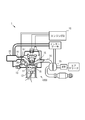
- FIG. 1 is an explanatory view showing a configuration example of an engine system equipped with a fuel injection valve of an embodiment.
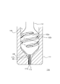
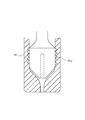
- FIG. 2 is an explanatory view showing a cross section of the main part of the fuel injection valve of the embodiment.
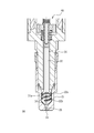
- FIG. 3 is an explanatory view showing a tip portion of the fuel injection valve of the embodiment,
- FIG. 3 (A) is a view showing a valve open state, and
- FIG. 3 (B) is a view showing a valve closed state.
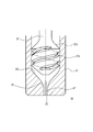
- FIG. 4 is an explanatory diagram showing air columns generated in the fuel injection valve.
- FIG. 5 is an explanatory diagram schematically showing how air columns are generated in the fuel injection valve.
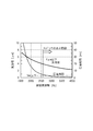
- FIG. 6 is a graph showing the relationship between the swirl frequency of the fuel, the bubble diameter, and the collapse time.
- FIG. 7 is an explanatory view showing a tip portion of another fuel injection valve.
- FIG. 8 is an explanatory view showing a tip portion of still another fuel injection valve.
- FIG. 9 is an explanatory view showing a tip portion of still another fuel injection valve.
- FIG. 10 is an explanatory diagram showing air columns generated in the fuel injection valve.
- FIG. 11 is an explanatory view showing a tip portion of still another fuel injection valve.
- FIG. 12 is an explanatory view schematically showing the inside of the fuel injection valve shown in FIG.
- FIG. 13 is an explanatory view showing a tip portion of still another fuel injection valve.
- FIG. 14 is an explanatory view showing a tip portion of still another fuel injection valve.
- FIG. 15 is an explanatory view showing a tip portion of still another fuel injection valve.
- FIG. 15 is an explanatory view showing a tip portion of still another fuel injection valve.
- FIG. 16 is an explanatory diagram showing an example of the dimensions of each part of the fuel injection valve.
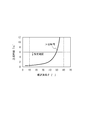
- FIG. 17 is an example of a graph showing the relationship between the spiral groove angle and the bubble collapse time.
- FIG. 18 is an example of a graph showing the relationship between the ratio of the diameter of the minimum throttle portion to the spiral diameter and the bubble collapse time.
- FIG. 19 is an example of a graph showing the relationship between the ratio of the spiral groove area to the area of the minimum throttle part and the bubble collapse time.
- FIG. 20 is an explanatory view showing a tip portion of another fuel injection valve.
- FIG. 1 is a diagram showing a configuration example of an engine system 1 equipped with a fuel injection valve 30 of the present invention.
- FIG. 1 shows only a part of the configuration of engine 1000.
- the engine system 1 shown in FIG. 1 includes an engine 1000 that is a power source, and includes an engine ECU (Electronic Control Unit) 10 that controls the overall operation of the engine 1000.
- the engine system 1 includes a fuel injection valve 30 that injects fuel into the combustion chamber 11 of the engine 1000.
- the engine ECU 10 has a function of a control unit.
- the engine ECU 10 includes a CPU (Central Processing Unit) that performs arithmetic processing, a ROM (Read Only Memory) that stores programs, a RAM (Random Access Memory) and NVRAM (Non Volatile RAM) that store data and the like. Computer.
- CPU Central Processing Unit
- ROM Read Only Memory
- RAM Random Access Memory
- NVRAM Non Volatile RAM
- the engine 1000 is an engine mounted on a vehicle and includes a piston 12 that constitutes a combustion chamber 11. Piston 12 is slidably fitted to a cylinder of engine 1000. And the piston 12 is connected with the crankshaft which is an output shaft member via the connecting rod.
- the intake air flowing into the combustion chamber 11 from the intake port 13 is compressed in the combustion chamber 11 by the upward movement of the piston 12.
- the engine ECU 10 determines the fuel injection timing based on the position of the piston 12 from the crank angle sensor and the information of the cam shaft rotation phase from the intake cam angle sensor, and sends a signal to the fuel injection valve 30.
- the fuel injection valve 30 injects fuel at an instructed injection timing in accordance with a signal from the engine ECU 10.
- the fuel injected from the fuel injection valve 30 is mixed with the atomized and compressed intake air. Then, the fuel mixed with the intake air is burned by being ignited by the spark plug 18, expands in the combustion chamber 11, and lowers the piston 12.
- the descending motion is changed to the rotation of the crankshaft through the connecting rod, whereby the engine 1000 obtains power.
- an intake port 13 that communicates with the combustion chamber 11 and an intake passage 14 that is connected to the intake port 13 and guides intake air from the intake port 13 to the combustion chamber 11. Further, an exhaust port 15 communicating with the combustion chamber 11 and an exhaust passage 16 that guides exhaust gas generated in the combustion chamber to the outside of the engine 1000 are connected to the combustion chamber 11 of each cylinder.
- a surge tank 22 is disposed in the intake passage 14.
- an air flow meter, a throttle valve 17, and a throttle position sensor are installed in the intake passage 14.
- the air flow meter and the throttle position sensor detect the amount of intake air passing through the intake passage 14 and the opening of the throttle valve 17, respectively, and transmit the detection results to the engine ECU 10.
- the engine ECU 10 recognizes the intake air amount introduced into the intake port 13 and the combustion chamber 11 based on the transmitted detection result, and adjusts the intake air amount by adjusting the opening of the throttle valve 17.
- a turbocharger 19 is installed in the exhaust passage 16.
- the turbocharger 19 uses the kinetic energy of the exhaust gas flowing through the exhaust passage 16 to rotate the turbine, compresses the intake air that has passed through the air cleaner, and sends it to the intercooler.
- the compressed intake air is cooled by the intercooler, temporarily stored in the surge tank 22, and then introduced into the intake passage 14.
- the engine 1000 is not limited to a supercharged engine provided with the turbocharger 19, and may be a natural aspiration engine.
- the piston 12 has a cavity on its top surface.
- a wall surface of the cavity is formed by a gentle curved surface continuous from the direction of the fuel injection valve 30 to the direction of the ignition plug 18, and the fuel injected from the fuel injection valve 30 is adjacent to the ignition plug 18 along the wall shape. Lead to.
- the piston 12 can form a cavity at an arbitrary position and shape according to the specifications of the engine 1000, such as a reentrant combustion chamber in which a cavity is formed in an annular shape at the center of the top surface.
- the fuel injection valve 30 is mounted in the combustion chamber 11 below the intake port 13.
- the fuel injection valve 30 directly injects fuel supplied at a high pressure from a fuel pump through a fuel flow path into the combustion chamber 11 through an injection hole 33 provided at the tip of the nozzle body 31 based on an instruction from the engine ECU 10.
- the injected fuel is atomized in the combustion chamber 11 and mixed with the intake air, and is guided to the vicinity of the spark plug 18 along the shape of the cavity.
- the leaked fuel from the fuel injection valve 30 is returned from the relief valve to the fuel tank through the relief pipe.
- the fuel injection valve 30 is not limited to the lower part of the intake port 13 and can be installed at an arbitrary position in the combustion chamber 11. For example, it can also arrange
- the engine 1000 may be any of a gasoline engine using gasoline as a fuel, a diesel engine using light oil as a fuel, and a flexible fuel engine using a fuel in which gasoline and alcohol are mixed in an arbitrary ratio.
- an engine using any fuel that can be injected by the fuel injection valve may be used.
- the engine system 1 may be a hybrid system in which the engine 1000 and a plurality of electric motors are combined.
- FIG. 2 is an explanatory view showing a main part of the fuel injection valve 30 as a cross section.
- FIG. 3 is an explanatory view showing a tip portion of the fuel injection valve of the embodiment, FIG. 3 (A) is a view showing a valve open state, and FIG. 3 (B) is a view showing a valve closed state.
- the fuel injection valve 30 includes a nozzle body 31, a needle 32, and a drive mechanism 40.
- the drive mechanism 40 controls the sliding operation of the needle 32.
- the drive mechanism 40 is a conventionally known mechanism including components suitable for the operation of the needle 32, such as an actuator using a piezoelectric element, an electromagnet, or an elastic member that applies an appropriate pressure to the needle 32.
- the distal end side indicates the lower side in the drawing
- the proximal end side indicates the upper side in the drawing.
- a nozzle hole 33 is provided at the tip of the nozzle body 31.
- the nozzle hole 33 is a single nozzle hole formed in the direction along the axis of the nozzle body 31 at the tip of the nozzle body 31.
- a seat portion 34 on which the needle 32 is seated is formed inside the nozzle body 31.
- the needle 32 is slidably disposed in the nozzle body 31 to form a fuel introduction path 36 between the needle 32 and the nozzle body 31. Then, by sitting on the seat portion 34 in the nozzle body 31, the fuel injection valve 30 is closed as shown in FIG.
- the needle 32 is pulled upward by the drive mechanism 40 and is separated from the seat portion 34 to open the valve as shown in FIG.
- the seat portion 34 is provided at a position recessed from the nozzle hole 33.
- the nozzle hole 33 is in a state where it is in communication with the outside, regardless of whether the needle 32 is in the valve open state or the valve closed state.
- the injection hole 33 is in communication with the combustion chamber 11.
- the fuel injection valve 30 is provided on the upstream side of the seat portion 34, and includes a swirl flow generating portion 32a that imparts a flow swirling in the sliding direction of the needle to the fuel introduced from the fuel introduction path 36. .
- the swirl flow generating unit 32 a is provided at the tip of the needle 32.
- the swirling flow generating unit 32 a has an enlarged diameter compared to the proximal end side of the needle 32.
- the leading end portion of the swirling flow generating unit 32 a is seated on the seat unit 34.
- the swirl flow generating unit 32a is located upstream of the seat unit 34 when the valve is opened and closed.
- the swirl flow generating unit 32a includes a spiral groove 32b. When the fuel introduced from the fuel introduction path 36 passes through the spiral groove 32b, a swirl component is added to the fuel flow, and a swirl flow fs of the fuel is generated.
- the fuel injection valve 30 includes a swirl speed increasing portion 35 that is provided on the downstream side of the seat portion 34 and supplies fuel to the nozzle hole 33 while increasing the swirling speed of the swirling flow generated in the swirling flow generating portion 32a. ing.
- the turning speed increasing portion 35 is formed by reducing the inner peripheral diameter toward the minimum throttle portion located downstream of the seat portion 34.
- the minimum throttling portion corresponds to a position having the smallest inner peripheral diameter in the downstream portion from the seat portion 34.
- the minimum throttle portion is an injection hole 33 as shown in FIGS. 3 (A) and 3 (B).
- the minimum throttle portion is not limited to the opening of the nozzle hole 33.
- the swirl speed increasing portion 35 is formed between the seat portion 34 and the nozzle hole 33, and accelerates the swirl speed of the fuel that has been swirled through the swirl flow generating portion 32a.
- the rotational radius of the swirl flow generated by the swirl flow generation unit 32a is gradually narrowed.
- the swirling flow fs flows into a narrow area with a reduced diameter, thereby increasing the swirling speed.
- the swirling flow fs whose swirling speed has increased forms an air column AP in the nozzle hole 33 as shown in FIG.
- the inner peripheral wall surface of the turning acceleration portion 35 has a curved surface that is convex toward the center side.
- FIG. 5 is an explanatory view showing the air column AP generated in the injection hole 33.
- a strong swirl flow fs is formed in the swirl speed increasing portion 35 from the nozzle hole 33, and a negative pressure is generated at the center where the strong swirl flow fs swirls.
- negative pressure is generated, air outside the nozzle body 31 is sucked into the nozzle body 31.
- an air column AP is generated in the nozzle hole 33.
- Bubbles are generated at the interface between the generated air column AP and the fuel. The generated bubbles are mixed into the fuel flowing around the air column, and are injected together with the fuel flow f 1 flowing on the outer peripheral side as the bubble mixed flow f 2 .
- the fuel flow f 1 and the bubble mixed flow f 2 form a cone-shaped spray s that diffuses from the center due to the centrifugal force of the swirling flow. Accordingly, since the diameter of the cone-shaped spray s increases as the distance from the nozzle hole 33 increases, the spray liquid film is stretched and thinned. Then, it cannot be maintained as a liquid film and splits. Thereafter, the spray after the splitting is reduced in diameter by the self-pressurizing effect of the fine bubbles, collapses and becomes an ultrafine spray. Thus, since the spray of the fuel injected by the fuel injection valve 30 is atomized, rapid flame propagation in the combustion chamber is realized, and stable combustion is performed.
- the fuel injection valve 30 When the fuel injection valve 30 is mounted in the combustion chamber 11, the gas introduced into the injection hole 33 becomes burned gas after the air-fuel mixture burns in the combustion chamber 11.
- the fuel injection valve according to the present embodiment does not need to have a separate structure for introducing gas into the fuel injection valve 30 in order to form the air column AP, and thus can have a simple configuration. This is also advantageous in terms of cost.
- the fuel injection valve 30 of the present embodiment can make the spray angle wide by the centrifugal force of the swirling flow of fuel. Thereby, mixing with air can be promoted.
- the spray contains bubbles, that is, a compressible gas, the critical speed (sound speed) at which sound propagates is reduced. Due to the physical property that the flow rate of fuel cannot exceed the speed of sound, the flow rate of fuel decreases as the speed of sound decreases. When the fuel flow rate is slow, the penetration is reduced, and the oil dilution in the bore wall is suppressed. Further, if the flow rate of the fuel is slowed by including bubbles, the nozzle hole diameter is set large in order to ensure the same fuel injection. Deposits accumulate in the nozzle holes.
- the injection amount changes due to the deposit accumulation.
- the sensitivity to changes in the injection amount (injection change amount) due to deposit accumulation decreases. That is, since the ratio of the injection change amount to the injection amount is reduced, the influence of the change in the injection amount due to deposit accumulation is reduced.
- the fuel injection valve 30 gradually reduces the turning radius by the turning acceleration portion 35, the turning flow fs is stabilized in the nozzle hole 33 serving as the minimum throttle portion, and the air column AP is generated stably.
- the air column AP is stably generated, the variation in the bubble diameter of the fine bubbles generated at the interface of the air column AP is suppressed.
- fluctuations in fuel injection including fine bubbles are suppressed.
- the particle size distribution of the fuel particles formed by the collapse of the injected fine bubbles is reduced, and a homogeneous spray can be obtained.
- the air column AP is stably formed, it is possible to obtain a spray with little variation in fuel particle size between cycles of the engine 1000.
- the fuel injection valve of the present embodiment generates fine bubbles by swirling the fuel in the swirling flow generating section 32a to form the air column AP.
- the swirl frequency of the fuel and the bubble diameter have a correlation.
- the bubble diameter and the bubble collapse time after fuel injection have a correlation. The relationship between these elements will be described with reference to FIG.
- the bubbles are crushed after being ejected from the nozzle hole 33 and before reaching the bore wall. If it is required that the time until collapse after injection is 3 ms (3 ms) or less, the bubble diameter is required to be 4 ⁇ m or less. And in order to implement
- the swirl flow generating unit 32a and the swirl speed increasing unit 35 are provided so as to realize a swirl frequency corresponding to the required crushing time.
- the fuel injection valve 30 according to the present embodiment includes the turning acceleration unit 35 to realize such a turning frequency.
- the center axes of the swirl flow generating section 32a, the swirl speed increasing section 35, and the injection hole 33 are matched, but these center axes do not necessarily have to match. .
- the center axis is allowed to deviate based on the convenience of installation of the fuel injection valve 30 in the engine 1000 and other requirements.
- FIG. 7 is an explanatory view showing the tip portion of the fuel injection valve 50 of the second embodiment.
- the basic configuration of the fuel injection valve 50 is the same as that of the fuel injection valve 30 of the first embodiment. That is, the fuel injection valve 50 includes a nozzle body 51, a needle 52, an injection hole 53, and a seat portion 54. A fuel introduction path 56 is formed in the fuel injection valve 50.
- the fuel injection valve 50 is also common to the fuel injection valve 30 in that it includes a swirl flow generating portion 52a and a spiral groove 52b.
- the fuel injection valve 30 and the fuel injection valve 50 differ in the following points. That is, the shape of the turning acceleration portion 55 is different from that of the turning acceleration portion 35. As shown in FIGS.
- the inner peripheral wall surface of the turning acceleration portion 35 has a curved surface that is convex toward the center side.
- the turning acceleration portion 55 has a mortar shape. Even in such a mortar shape, the inner peripheral diameter is reduced toward the smallest throttle part (injection hole 53) located downstream of the sheet part 54, and thus is generated by the swirl flow generation part 52a. The swirling flow can be accelerated. Thereby, the point that the air column AP is formed is the same as in the case of the fuel injection valve 30. In addition, the fuel injection valve 50 is common to the fuel injection valve 30 in other effects.
- FIG. 8 is an explanatory view showing the tip portion of the fuel injection valve 70 of the third embodiment.
- the basic configuration of the fuel injection valve 70 is the same as that of the fuel injection valve 30 of the first embodiment. That is, the fuel injection valve 70 includes a nozzle body 71, a needle 72, an injection hole 73, and a seat portion 74. Further, a fuel introduction path 76 is formed in the fuel injection valve 70.
- the fuel injection valve 70 is also in common with the fuel injection valve 30 in that it includes a swirl flow generator 72a and a spiral groove 72b.
- the fuel injection valve 30 and the fuel injection valve 70 differ in the following points. That is, the shape of the turning acceleration portion 75 is different from that of the turning acceleration portion 35.
- the inner peripheral wall surface of the turning acceleration portion 35 has a curved surface that is convex toward the center side.
- the turning acceleration part 75 has a shape similar to a cone. Even in such a shape similar to a cone, since the inner peripheral diameter is reduced toward the minimum throttle portion (injection hole 73) located downstream of the seat portion 74, the swirling flow generating portion 72a The swirl flow generated in can be accelerated. Thereby, the point that the air column AP is formed is the same as in the case of the fuel injection valve 30. In addition, the fuel injection valve 70 is common to the fuel injection valve 30 in other effects.
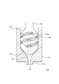
- FIG. 9 is an explanatory view showing the tip portion of the fuel injection valve 90 of the fourth embodiment.
- FIG. 10 is an explanatory view showing the air column AP generated in the fuel injection valve 90.
- the basic configuration of the fuel injection valve 90 is common to the fuel injection valve 30 of the first embodiment. That is, the fuel injection valve 90 includes a nozzle body 91, a needle 92, an injection hole 93, and a seat portion 94. A fuel introduction path 96 is formed in the fuel injection valve 90.
- the fuel injection valve 90 is also common to the fuel injection valve 30 in that it includes a swirl flow generating portion 92a and a spiral groove 92b. Moreover, the point provided with the turning acceleration part 95 is also common.
- the fuel injection valve 30 and the fuel injection valve 90 differ in the following points. That is, the injection hole 93 of the fuel injection valve 90 is provided at a position facing the needle 92, and the needle 92 includes an air storage chamber 92 c that faces the injection hole 93 at the front end of the combustion chamber.
- the air storage chamber is a cavity provided in the needle 92.
- the burned gas sucked from the outside (combustion chamber side) by the negative pressure generated by the swirling flow in the nozzle hole 93 and the residual gas in the air storage chamber 92c are combined to form the air column AP. It is formed. For this reason, the length of the air column AP increases. As a result, the interface area of the air column AP increases, and the amount of bubble generation increases. As the amount of bubbles generated increases, the bubble density during spraying increases, and the membrane pressure of the bubbles due to fuel decreases. If the membrane pressure is reduced, the burst time (crush time) is shortened. Further, the spray particle size is further reduced and homogenized. Thereby, since the droplet fuel does not reach the top of the combustion chamber, knocking is suppressed.
- the air column AP itself is stably formed. This also reduces the particle size distribution of the spray particle size and homogenizes it. As a result, it is possible to obtain a spray with little variation in fuel particle size between cycles of the engine 1000. These contribute to PM reduction, HC reduction, and thermal efficiency improvement. Furthermore, since stable operation with less combustion fluctuations of the engine 1000 is possible, it is possible to improve fuel efficiency, reduce harmful exhaust gas, increase EGR (Exhaust Gas Recirculation), and lean A / F (air-fuel ratio). .
- EGR exhaust Gas Recirculation
- lean A / F air-fuel ratio
- the weight of the needle 92 which is a movable part can be reduced.
- the responsiveness of the needle 92 is improved.
- the output required for the drive mechanism 40 that drives the needle 92 is reduced, resulting in a cost reduction.
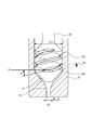
- FIG. 11 is an explanatory view showing the tip portion of the fuel injection valve 110 of the fifth embodiment.
- FIG. 12 is an explanatory view schematically showing the inside of the fuel injection valve 110 shown in FIG.
- the basic configuration of the fuel injection valve 110 is the same as that of the fuel injection valve 30 of the first embodiment. That is, the fuel injection valve 110 includes a nozzle body 111, a needle 112, an injection hole 113, and a seat portion 114. In addition, a fuel introduction path 116 is formed in the fuel injection valve 110.
- the fuel injection valve 110 is also in common with the fuel injection valve 30 in that it includes a swirl flow generation unit 112a and a spiral groove 112b.
- the point provided with the turning acceleration part 115 is also common.
- the fuel injection valve 30 and the fuel injection valve 110 differ in the following points. That is, the needle 112 of the fuel injection valve 110 includes a porous member 117 at the combustion chamber side tip.
- the porous member 117 includes an opening 117 a that extends toward the injection hole 113 and faces the injection hole 113.
- the porous member 117 moves along the axial direction of the needle 112 in the turning acceleration portion 115 as the needle 112 moves up and down.
- the porous member 117 may be a cylindrical member that is open at both ends and penetrated inside, or may be a bottomed cylindrical member.
- FIG. 11 shows an example of a bottomed cylindrical member.
- the needle 112 may be provided with an air storage chamber as in the fifth embodiment.
- the porous member 117 may be combined with an air storage chamber as a cylindrical member having openings at both ends.
- the porous member 117 is attached to the tip of the needle 112 by adhesion, but can be attached by other methods such as press-fitting or screwing.
- the burnt gas introduced into the porous member 117 from the opening 117a of the porous member 117 passes through the micropores of the porous member 117 as shown by the arrow 118 and becomes porous. Supplied to the fuel swirling outside the mass member 117. For this reason, even when the conditions are such that the speed of the swirling flow in the nozzle hole 113 decreases at a low fuel pressure, fine bubbles can be generated and mixed into the swirling flow.
- the external dimension of the porous member 117 of Example 5 is set to 1/4 or more of the diameter of the nozzle hole 113. This is due to the following reason. According to the experiment, the ratio of the diameter of the air column AP to the nozzle hole diameter was about 0.12. Generally, the gas that passes through the micropores from the inside of the porous member 117 is immediately bonded to each other when the gas is present outside the porous member 117. For this reason, bubbles are not formed. In order to generate bubbles, liquid must exist outside the porous member 117. Considering this, the outer diameter of the porous member 117 must be larger than the diameter of the air column AP formed in the nozzle hole 113. As a dimension that can satisfy this condition, the outer diameter of the porous member 117 in Example 5 is set to 1 ⁇ 4 or more of the diameter of the injection hole 113.
- the gas passing through the micropores of the porous member 117 is likely to be bonded if the swirl speed is low. Is also possible.
- the swirl flow is such that a negative pressure is generated at the swirl center, the bubbles are considered to be dispersed in the fuel before the gas is combined.
- ultrafine bubbles are not deformed or coalesced even when they collide with each other or interact with turbulent airflow, as with a hard sphere. This has been confirmed by experiments. For this reason, it is possible to mix the target fine bubbles in the fuel.
- Example 6 is an explanatory view showing the tip portion of the fuel injection valve 110 of the sixth embodiment.
- the sixth embodiment is almost in common with the fifth embodiment. For this reason, common components are given the same reference numerals in the drawings, and detailed descriptions thereof are omitted.
- Example 6 differs from Example 5 in the shape of the tip of the porous member 117. That is, the outer diameter of the combustion chamber side tip portion 117b of the porous member 117 in Example 6 is reduced toward the tip. That is, it has an R shape (hemispherical shape) as shown in an enlarged view in FIG.
- the shape of the combustion chamber side tip portion 117b may be, for example, a tapered shape.
- the following effects can be obtained by reducing the outer diameter of the combustion chamber side front end portion 117b toward the front end.
- the fuel can be made to conform to the shape of the combustion chamber side tip portion 117b as indicated by an arrow 119, and the spray angle can be narrowed.
- the spray trajectory 120 can be narrowed like the spray trajectory 121.
- FIG. 14 is an explanatory view showing the tip portion of the fuel injection valve 130 of the seventh embodiment.
- the basic configuration of the fuel injection valve 130 is the same as that of the fuel injection valve 30 of the first embodiment. That is, the fuel injection valve 130 includes a nozzle body 131, a needle 132, an injection hole 133, and a seat part 134. A fuel introduction path 136 is formed in the fuel injection valve 130.
- the fuel injection valve 130 is also in common with the fuel injection valve 30 in that it includes a swirl flow generation unit 132a and a spiral groove 132b. Moreover, the point provided with the turning acceleration part 135 is also common.
- the fuel injection valve 30 and the fuel injection valve 130 differ in the following points.
- the nozzle body 131 of the fuel injection valve 130 has a shape in which the periphery where the injection hole 133 is opened protrudes toward the combustion chamber. Specifically, the tapered surface 131 a is formed so that the outer diameter decreases toward the tip of the nozzle body 131.
- the spray angle is widened.
- the spray sprayed by the Coanda effect spreads along the outer wall surface of the nozzle body.
- the spray angle is further expanded.
- the spray angle is excessively wide in this way, the spray spreads in a state of craving the wall surface of the combustion chamber, and the homogenization of the air-fuel mixture may be impaired. Therefore, the Coanda effect is suppressed by protruding the periphery of the nozzle body 131 where the injection hole 133 is opened toward the combustion chamber. As a result, the spread of the spray angle can be suppressed, and the air-fuel mixture can be homogenized stably.
- FIG. 15 is an explanatory view showing the tip portion of the fuel injection valve 150 of the eighth embodiment.
- the basic configuration of the fuel injection valve 150 is the same as that of the fuel injection valve 130 of the seventh embodiment. That is, the fuel injection valve 150 includes a nozzle body 151, a needle 152, an injection hole 153, and a seat portion 154. A fuel introduction path 156 is formed in the fuel injection valve 150.
- the fuel injection valve 150 is also in common with the fuel injection valve 130 in that it includes a swirl flow generation unit 152a and a spiral groove 152b. Moreover, the point provided with the turning acceleration part 155 is also common.
- the nozzle body 151 of the fuel injection valve 150 is also in common with the fuel injection valve 130 in that the periphery around the injection hole 153 is protruded toward the combustion chamber.
- both differ in the specific shape. That is, the fuel injection valve 130 includes a tapered surface 131a whose outer diameter decreases toward the tip of the nozzle body 131, whereas the fuel injection valve 150 includes a convex portion 151a.
- the fuel injection valve 150 provided with such a convex portion 151a can also suppress the Coanda effect. As a result, the spread of the spray angle can be suppressed, and the mixture can be stably homogenized.
- FIG. 16 is an explanatory view showing an example of the dimensions of each part of the fuel injection valve 30.
- FIG. 17 is an example of a graph showing the relationship between the spiral groove angle ⁇ and the bubble collapse time.
- FIG. 18 is an example of a graph showing the relationship between the ratio of the diameter Dh of the minimum throttle portion to the spiral diameter Ds and the bubble collapse time.
- FIG. 19 is an example of a graph showing the relationship between the ratio of the spiral groove area Ag to the channel area Ah of the minimum throttle part and the bubble collapse time.
- the present Example demonstrates the item of each part using the fuel injection valve 30 demonstrated in Example 1, the same item can be employ
- the specifications are determined in consideration of the bore diameter of a general vehicle engine being 180 mm or less.
- the specifications are determined so that the fine bubbles injected from the injection hole 33 of the fuel injection valve 30 mounted in the center of the combustion chamber are crushed before reaching the bore wall.
- the bore diameter is 180 mm, it takes 6 ms for the sprayed spray to reach the bore wall. Therefore, it is required that the fine bubbles are crushed within 6 ms after the injection from the injection hole 33.
- the specifications are determined in consideration of this. Each specification has a certain range, and can be appropriately changed according to the specification of the engine 1000 to be applied.
- the time to reach the bore wall is half 3 ms, so each specification is determined so that the collapse time is 3 ms or less.
- the arrival time to the bore wall is calculated with a fuel pressure of 2 MPa, an initial spray speed of about 45 m / s, and an average spray speed of about 15 m / s.
- the swirl flow generating unit 32a includes a spiral groove 32b.
- an angle between the spiral groove 32b and a direction PL orthogonal to the sliding direction (center axis AX direction) of the needle 32 is defined as a spiral groove angle ⁇ .
- the spiral groove angle ⁇ at which the crush time is 6 ms is 0 ⁇ ⁇ 49 ° It becomes. If it is desired to set the crush time to 3 ms or less, it may be set to about 0 ⁇ ⁇ 42 °.
- the diameter Dh of the minimum throttle portion corresponds to the nozzle hole diameter.
- the spiral diameter Ds corresponds to the diameter of the swirl flow generation unit 32a. Referring to FIG. 18, the ratio of the diameter Dh of the minimum throttling portion with a collapse time of 6 ms to the helical diameter Ds is 7 to 19%.
- the swirling flow flows from the spiral groove 32b to the injection hole 33 while being accelerated at a ratio of 1 / (Dh / Ds) 2 .
- a negative pressure is generated at the center of the turning, and the burned gas in the fuel chamber is sucked to generate an air column.
- the spiral groove area Ag is the fuel flow path area of the spiral groove 32b as shown in FIG.
- the channel area Ah of the minimum throttle portion is the channel area of the nozzle hole 33.
- the ratio of the spiral groove area Ag at which the crushing time is 6 ms to the flow path area Ah of the minimum throttle portion is 0.4 to 1.3.
- the specifications can be determined. Each item can be set so that the required collapse time can be realized. As the fuel pressure increases, the bubble diameter becomes smaller, so that the allowable range of specifications is expanded.
- each of the above embodiments has a swirl flow generating portion having a spiral groove in the needle, but for example, as shown in FIG. 20, a spiral groove 161a is provided on the inner peripheral wall of the nozzle body 161, thereby A swirling flow of fuel may be generated.
Landscapes
- Engineering & Computer Science (AREA)
- Chemical & Material Sciences (AREA)
- Combustion & Propulsion (AREA)
- Mechanical Engineering (AREA)
- General Engineering & Computer Science (AREA)
- Fuel-Injection Apparatus (AREA)
Abstract
Description
まず、旋回溝角度θの範囲について説明する。旋回流生成部32aは、螺旋溝32bを備えている。ここで、この螺旋溝32bがニードル32の摺動方向(中心軸AX方向)との直交する方向PLとの角度を螺旋溝角θとする。図17を参照すると、圧壊時間6msとなる螺旋溝角θは、
0<θ≦49°
となる。なお、圧壊時間を3ms以下に設定したい場合は、0<θ≦42°程度に設定すればよい。
実施例の燃料噴射弁30において、最小絞り部の径Dhは、噴孔径に相当する。螺旋径Dsは、旋回流生成部32aの径に相当する。図18を参照すると、圧壊時間6msとなる最小絞り部の径Dhの螺旋径Dsに対する比は、7~19%である。
螺旋溝面積Agは図16に示すように螺旋溝32bの燃料流路面積である。最小絞り部の流路面積Ahは、噴孔33の流路面積である。図19を参照すると、圧壊時間6msとなる螺旋溝面積Agと最小絞り部の流路面積Ahとの比は、0.4~1.3である。
30、50、70、90、110、130、150 燃料噴射弁
31、51、71、91、111、131、151、161 ノズルボディ
32、52、72、92、112、132 ニードル
131b 先端突出部
32a、52a、72a、92a、112a、132a 旋回流生成部
32b、52b、72b、92b、112b、132b、161a 螺旋溝
92c 貯気室
33、53、73、93、113、133、153 噴孔(最小絞り部)
34、54、74、94、114、134、154 シート部
35、55、75、95、115、135、155 旋回増速部
36、56、76、96、116、136、156 燃料導入路
117 多孔質部材
117a 開口
117b 燃焼室側先端部
120、121 噴霧軌跡
1000 エンジン
AP 気柱
f1 燃料流
f2 気泡混入流
fs 旋回流
θ 旋回溝角
Ag 螺旋溝面積
Ds 螺旋径
Dh 最小絞り径(噴孔径)
Ah 最小絞り部の流路面積(噴孔面積)
Claims (7)
- 先端部に噴孔が設けられたノズルボディと、
前記ノズルボディ内に摺動自在に配置され、前記ノズルボディとの間に燃料導入路を形成するとともに、前記ノズルボディ内のシート部に着座するニードルと、
前記シート部よりも上流側に設けられ、前記燃料導入路から導入される燃料に前記ニードルの摺動方向に対して旋回する流れを付与する旋回流生成部と、
前記シート部よりも下流側に設けられ、前記旋回流生成部において生成された旋回流の旋回速度を増大させつつ前記噴孔へ燃料を供給する旋回増速部と、を備えたことを特徴とする燃料噴射弁。 - 前記旋回増速部は、前記シート部よりも下流部に位置する最小絞り部に向かって内周径が縮径して形成されたことを特徴とする請求項1記載の燃料噴射弁。
- 前記噴孔は、前記ニードルと対向する位置に設けられ、前記ニードルは、燃焼室側先端部に前記噴孔と対向する貯気室を備えたことを特徴とする請求項1又は2記載の燃料噴射弁。
- 前記ニードルは、燃焼室側先端部に多孔質部材を備え、当該多孔質部材は、前記噴孔に向かって延びるとともに、前記噴孔と対向する開口を備えたことを特徴とする請求項1乃至3のいずれか一項記載の燃料噴射弁。
- 前記多孔質部材の燃焼室側先端部の外径は、先端に向かうに従って縮径されていることを特徴とする請求項4記載の燃焼噴射弁。
- 前記ノズルボディは、前記噴孔が開口した周囲を燃焼室側に突出させたことを特徴とする請求項1乃至5のいずれか一項記載の燃料噴射弁。
- 前記旋回流生成部は、螺旋溝を備え、当該螺旋溝の前記ニードルの摺動方向と直交する方向との角度θは、0<θ≦49°であり、前記最小絞り部の径は、前記旋回流生成部の径の7~19%であり、前記螺旋溝の燃料流路面積と前記最小絞り部の流路面積との比は、0.4~1.3であることを特徴とした請求項1乃至6のいずれか一項記載の燃料噴射弁。
Priority Applications (5)
| Application Number | Priority Date | Filing Date | Title |
|---|---|---|---|
| US13/994,879 US20130277453A1 (en) | 2010-12-20 | 2010-12-20 | Fuel injection valve |
| PCT/JP2010/072940 WO2012086005A1 (ja) | 2010-12-20 | 2010-12-20 | 燃料噴射弁 |
| EP10860948.8A EP2657506B1 (en) | 2010-12-20 | 2010-12-20 | Fuel injection valve |
| JP2012549507A JP5678966B2 (ja) | 2010-12-20 | 2010-12-20 | 燃料噴射弁 |
| CN201080070758.2A CN103261662B (zh) | 2010-12-20 | 2010-12-20 | 燃料喷射阀 |
Applications Claiming Priority (1)
| Application Number | Priority Date | Filing Date | Title |
|---|---|---|---|
| PCT/JP2010/072940 WO2012086005A1 (ja) | 2010-12-20 | 2010-12-20 | 燃料噴射弁 |
Publications (1)
| Publication Number | Publication Date |
|---|---|
| WO2012086005A1 true WO2012086005A1 (ja) | 2012-06-28 |
Family
ID=46313309
Family Applications (1)
| Application Number | Title | Priority Date | Filing Date |
|---|---|---|---|
| PCT/JP2010/072940 WO2012086005A1 (ja) | 2010-12-20 | 2010-12-20 | 燃料噴射弁 |
Country Status (5)
| Country | Link |
|---|---|
| US (1) | US20130277453A1 (ja) |
| EP (1) | EP2657506B1 (ja) |
| JP (1) | JP5678966B2 (ja) |
| CN (1) | CN103261662B (ja) |
| WO (1) | WO2012086005A1 (ja) |
Cited By (2)
| Publication number | Priority date | Publication date | Assignee | Title |
|---|---|---|---|---|
| US9194323B2 (en) | 2011-03-31 | 2015-11-24 | Toyota Jidosha Kabushiki Kaisha | Fuel injection device |
| JP2016061219A (ja) * | 2014-09-18 | 2016-04-25 | 日立オートモティブシステムズ株式会社 | 燃料噴射弁 |
Families Citing this family (11)
| Publication number | Priority date | Publication date | Assignee | Title |
|---|---|---|---|---|
| CN104712481B (zh) * | 2014-06-16 | 2017-01-18 | 北京航空航天大学 | 一种微通道热泡式燃油喷射系统 |
| CN104265530B (zh) * | 2014-07-31 | 2016-08-31 | 中国第一汽车股份有限公司无锡油泵油嘴研究所 | 电控内燃机喷射器控制阀 |
| RU2719034C2 (ru) * | 2014-12-31 | 2020-04-16 | Сосьете Де Продюи Нестле С.А. | Способ контроля размера распыленных капель в распылительном насадочном устройстве для распылительной сушки, аппарат для распылительной сушки и насадка к нему |
| JP2017008859A (ja) * | 2015-06-24 | 2017-01-12 | 株式会社日本自動車部品総合研究所 | 燃料噴射ノズル |
| JP6384427B2 (ja) * | 2015-08-25 | 2018-09-05 | トヨタ自動車株式会社 | 内燃機関の制御装置 |
| RU2673649C1 (ru) * | 2017-07-25 | 2018-11-28 | федеральное государственное бюджетное образовательное учреждение высшего образования "Ставропольский государственный аграрный университет" | Распылитель дизельной форсунки |
| CN108561250B (zh) * | 2018-01-17 | 2019-11-26 | 湖南农业大学 | 一种循环式内燃机喷油系统 |
| CN108561249B (zh) * | 2018-01-17 | 2019-11-26 | 湖南农业大学 | 一种雾化式内燃机喷油系统的运维方法 |
| CN108266299B (zh) * | 2018-01-17 | 2019-11-26 | 湖南农业大学 | 一种电控内燃机喷油电磁阀 |
| CN108266300B (zh) * | 2018-01-17 | 2019-11-26 | 湖南农业大学 | 一种自调压内燃机喷油系统电磁阀的工作方法 |
| CN108252836B (zh) * | 2018-01-17 | 2019-11-26 | 湖南农业大学 | 一种雾化式内燃机喷油电磁阀 |
Citations (7)
| Publication number | Priority date | Publication date | Assignee | Title |
|---|---|---|---|---|
| JPS6264868U (ja) * | 1985-10-12 | 1987-04-22 | ||
| JPH10184497A (ja) * | 1996-12-25 | 1998-07-14 | Zexel Corp | 燃料噴射ノズル |
| JP2003307165A (ja) * | 2002-04-15 | 2003-10-31 | Mitsubishi Electric Corp | 燃料噴射装置 |
| JP2004506138A (ja) * | 2000-08-04 | 2004-02-26 | ローベルト ボツシユ ゲゼルシヤフト ミツト ベシユレンクテル ハフツング | 燃料噴射弁 |
| JP2006177174A (ja) * | 2004-12-20 | 2006-07-06 | Toyota Central Res & Dev Lab Inc | 燃料噴射弁 |
| WO2007013165A1 (ja) * | 2005-07-29 | 2007-02-01 | Mitsubishi Denki Kabushiki Kaisha | 燃料噴射弁 |
| WO2007091536A1 (ja) * | 2006-02-07 | 2007-08-16 | Mikuni Corporation | 燃料噴射弁 |
Family Cites Families (10)
| Publication number | Priority date | Publication date | Assignee | Title |
|---|---|---|---|---|
| GB1440435A (en) * | 1972-07-20 | 1976-06-23 | Cav Ltd | Fuel injection nozzle units |
| JPS60138270A (ja) * | 1983-12-27 | 1985-07-22 | Nippon Denso Co Ltd | 内燃機関用の燃料噴射ノズル |
| CN1187233A (zh) * | 1995-06-09 | 1998-07-08 | 株式会社杰克赛尔 | 喷孔面积可变的燃料喷嘴 |
| US6302080B1 (en) * | 1998-07-31 | 2001-10-16 | Denso Corporation | Fuel injection system having pre-injection and main injection |
| JP4085713B2 (ja) * | 2002-06-19 | 2008-05-14 | 日産自動車株式会社 | 直接噴射式内燃機関の燃料噴射弁 |
| KR100468207B1 (ko) * | 2003-08-14 | 2005-01-26 | 곽쌍신 | 연료분사장치 |
| JP4102288B2 (ja) * | 2003-10-31 | 2008-06-18 | トヨタ自動車株式会社 | 燃料噴射装置 |
| JP4034263B2 (ja) * | 2003-12-25 | 2008-01-16 | 三菱電機株式会社 | 燃料噴射弁及びスワラー製造方法 |
| JP4335280B2 (ja) * | 2006-11-27 | 2009-09-30 | 三菱電機株式会社 | 燃料噴射弁 |
| DE102008031271B4 (de) * | 2008-07-02 | 2011-07-28 | Continental Automotive GmbH, 30165 | Düsenbaugruppe für ein Einspritzventil |
-
2010
- 2010-12-20 US US13/994,879 patent/US20130277453A1/en not_active Abandoned
- 2010-12-20 EP EP10860948.8A patent/EP2657506B1/en not_active Not-in-force
- 2010-12-20 JP JP2012549507A patent/JP5678966B2/ja not_active Expired - Fee Related
- 2010-12-20 CN CN201080070758.2A patent/CN103261662B/zh not_active Expired - Fee Related
- 2010-12-20 WO PCT/JP2010/072940 patent/WO2012086005A1/ja active Application Filing
Patent Citations (7)
| Publication number | Priority date | Publication date | Assignee | Title |
|---|---|---|---|---|
| JPS6264868U (ja) * | 1985-10-12 | 1987-04-22 | ||
| JPH10184497A (ja) * | 1996-12-25 | 1998-07-14 | Zexel Corp | 燃料噴射ノズル |
| JP2004506138A (ja) * | 2000-08-04 | 2004-02-26 | ローベルト ボツシユ ゲゼルシヤフト ミツト ベシユレンクテル ハフツング | 燃料噴射弁 |
| JP2003307165A (ja) * | 2002-04-15 | 2003-10-31 | Mitsubishi Electric Corp | 燃料噴射装置 |
| JP2006177174A (ja) * | 2004-12-20 | 2006-07-06 | Toyota Central Res & Dev Lab Inc | 燃料噴射弁 |
| WO2007013165A1 (ja) * | 2005-07-29 | 2007-02-01 | Mitsubishi Denki Kabushiki Kaisha | 燃料噴射弁 |
| WO2007091536A1 (ja) * | 2006-02-07 | 2007-08-16 | Mikuni Corporation | 燃料噴射弁 |
Non-Patent Citations (1)
| Title |
|---|
| See also references of EP2657506A4 * |
Cited By (2)
| Publication number | Priority date | Publication date | Assignee | Title |
|---|---|---|---|---|
| US9194323B2 (en) | 2011-03-31 | 2015-11-24 | Toyota Jidosha Kabushiki Kaisha | Fuel injection device |
| JP2016061219A (ja) * | 2014-09-18 | 2016-04-25 | 日立オートモティブシステムズ株式会社 | 燃料噴射弁 |
Also Published As
| Publication number | Publication date |
|---|---|
| CN103261662A (zh) | 2013-08-21 |
| CN103261662B (zh) | 2016-01-20 |
| US20130277453A1 (en) | 2013-10-24 |
| EP2657506B1 (en) | 2015-10-14 |
| JPWO2012086005A1 (ja) | 2014-05-22 |
| EP2657506A1 (en) | 2013-10-30 |
| EP2657506A4 (en) | 2014-01-15 |
| JP5678966B2 (ja) | 2015-03-04 |
Similar Documents
| Publication | Publication Date | Title |
|---|---|---|
| JP5678966B2 (ja) | 燃料噴射弁 | |
| JP5494824B2 (ja) | 燃料噴射弁 | |
| JP5614459B2 (ja) | 燃料噴射弁 | |
| JP5115659B2 (ja) | 燃料噴射弁 | |
| JP5115654B2 (ja) | 燃料噴射弁及び内燃機関 | |
| JP5725150B2 (ja) | 燃料噴射弁 | |
| US20150292460A1 (en) | Fuel injection valve | |
| JP2013204455A (ja) | 燃料噴射弁 | |
| JP2012137053A (ja) | 燃料噴射弁 | |
| JP2012132366A (ja) | 燃料噴射弁 | |
| JP4043966B2 (ja) | 燃料噴射弁 | |
| JP5983535B2 (ja) | 燃料噴射弁 | |
| JP2012132332A (ja) | 燃料噴射弁及び燃料噴射装置 | |
| JP2014156794A (ja) | 燃料噴射弁 | |
| WO2011125154A1 (ja) | 燃料噴射弁及び燃料噴射装置 | |
| JP2012172673A (ja) | 燃料噴射弁及び燃料噴射装置 | |
| JP2012132334A (ja) | 燃料噴射弁 | |
| JP5803792B2 (ja) | 燃料噴射装置 | |
| JP2014047665A (ja) | 燃料噴射弁 | |
| JP2007224929A (ja) | 燃料噴射弁 |
Legal Events
| Date | Code | Title | Description |
|---|---|---|---|
| 121 | Ep: the epo has been informed by wipo that ep was designated in this application |
Ref document number: 10860948 Country of ref document: EP Kind code of ref document: A1 |
|
| ENP | Entry into the national phase |
Ref document number: 2012549507 Country of ref document: JP Kind code of ref document: A |
|
| WWE | Wipo information: entry into national phase |
Ref document number: 2010860948 Country of ref document: EP |
|
| WWE | Wipo information: entry into national phase |
Ref document number: 13994879 Country of ref document: US |
|
| NENP | Non-entry into the national phase |
Ref country code: DE |