WO2012073611A1 - 建設機械 - Google Patents
建設機械 Download PDFInfo
- Publication number
- WO2012073611A1 WO2012073611A1 PCT/JP2011/074132 JP2011074132W WO2012073611A1 WO 2012073611 A1 WO2012073611 A1 WO 2012073611A1 JP 2011074132 W JP2011074132 W JP 2011074132W WO 2012073611 A1 WO2012073611 A1 WO 2012073611A1
- Authority
- WO
- WIPO (PCT)
- Prior art keywords
- box body
- air
- indoor unit
- floor member
- unit
- Prior art date
Links
Images


Classifications
-
- E—FIXED CONSTRUCTIONS
- E02—HYDRAULIC ENGINEERING; FOUNDATIONS; SOIL SHIFTING
- E02F—DREDGING; SOIL-SHIFTING
- E02F9/00—Component parts of dredgers or soil-shifting machines, not restricted to one of the kinds covered by groups E02F3/00 - E02F7/00
- E02F9/08—Superstructures; Supports for superstructures
-
- B—PERFORMING OPERATIONS; TRANSPORTING
- B60—VEHICLES IN GENERAL
- B60H—ARRANGEMENTS OF HEATING, COOLING, VENTILATING OR OTHER AIR-TREATING DEVICES SPECIALLY ADAPTED FOR PASSENGER OR GOODS SPACES OF VEHICLES
- B60H1/00—Heating, cooling or ventilating [HVAC] devices
- B60H1/00357—Air-conditioning arrangements specially adapted for particular vehicles
- B60H1/00378—Air-conditioning arrangements specially adapted for particular vehicles for tractor or load vehicle cabins
-
- E—FIXED CONSTRUCTIONS
- E02—HYDRAULIC ENGINEERING; FOUNDATIONS; SOIL SHIFTING
- E02F—DREDGING; SOIL-SHIFTING
- E02F3/00—Dredgers; Soil-shifting machines
- E02F3/04—Dredgers; Soil-shifting machines mechanically-driven
- E02F3/28—Dredgers; Soil-shifting machines mechanically-driven with digging tools mounted on a dipper- or bucket-arm, i.e. there is either one arm or a pair of arms, e.g. dippers, buckets
- E02F3/30—Dredgers; Soil-shifting machines mechanically-driven with digging tools mounted on a dipper- or bucket-arm, i.e. there is either one arm or a pair of arms, e.g. dippers, buckets with a dipper-arm pivoted on a cantilever beam, i.e. boom
- E02F3/32—Dredgers; Soil-shifting machines mechanically-driven with digging tools mounted on a dipper- or bucket-arm, i.e. there is either one arm or a pair of arms, e.g. dippers, buckets with a dipper-arm pivoted on a cantilever beam, i.e. boom working downwardly and towards the machine, e.g. with backhoes
- E02F3/325—Backhoes of the miniature type
-
- E—FIXED CONSTRUCTIONS
- E02—HYDRAULIC ENGINEERING; FOUNDATIONS; SOIL SHIFTING
- E02F—DREDGING; SOIL-SHIFTING
- E02F9/00—Component parts of dredgers or soil-shifting machines, not restricted to one of the kinds covered by groups E02F3/00 - E02F7/00
- E02F9/08—Superstructures; Supports for superstructures
- E02F9/0858—Arrangement of component parts installed on superstructures not otherwise provided for, e.g. electric components, fenders, air-conditioning units
-
- E—FIXED CONSTRUCTIONS
- E02—HYDRAULIC ENGINEERING; FOUNDATIONS; SOIL SHIFTING
- E02F—DREDGING; SOIL-SHIFTING
- E02F9/00—Component parts of dredgers or soil-shifting machines, not restricted to one of the kinds covered by groups E02F3/00 - E02F7/00
- E02F9/16—Cabins, platforms, or the like, for drivers
- E02F9/166—Cabins, platforms, or the like, for drivers movable, tiltable or pivoting, e.g. movable seats, dampening arrangements of cabins
-
- B—PERFORMING OPERATIONS; TRANSPORTING
- B60—VEHICLES IN GENERAL
- B60H—ARRANGEMENTS OF HEATING, COOLING, VENTILATING OR OTHER AIR-TREATING DEVICES SPECIALLY ADAPTED FOR PASSENGER OR GOODS SPACES OF VEHICLES
- B60H1/00—Heating, cooling or ventilating [HVAC] devices
- B60H1/00007—Combined heating, ventilating, or cooling devices
- B60H1/00207—Combined heating, ventilating, or cooling devices characterised by the position of the HVAC devices with respect to the passenger compartment
- B60H2001/00221—Devices in the floor or side wall area of the passenger compartment
Definitions
- the present invention relates to a construction machine such as a hydraulic excavator provided with an indoor unit on a floor member, for example.
- a hydraulic excavator as a construction machine is provided with a self-propelled lower traveling body, an upper revolving body that is turnably mounted on the lower traveling body, and a front-rear side of the upper revolving body that can be raised and lowered. It is roughly constituted by a working device.
- the upper swing body includes a swing frame that forms a support structure, an engine that is provided on the rear side of the swing frame to drive a hydraulic pump, and is provided on the swing frame that is positioned on the front side of the engine and is operated on the rear side.
- a floor member that serves as a driver seat mounting portion for attaching a seat and the front side is a footrest portion on which an operator can put his / her foot, and the periphery and upper portion of the floor member are provided to form a driver's cab on the floor member
- a cab box and an air conditioner that supplies conditioned air to the cab are provided to improve the working environment of the cab.
- the air conditioner is formed by connecting an outdoor unit on the engine side and an indoor unit on the floor member side by a refrigerant pipe.
- the outdoor unit on the engine side includes a condenser that is located in the middle of the refrigerant pipe and cools the refrigerant with cooling air from the cooling fan of the engine.
- the indoor unit on the floor member side has a fan that creates an air flow toward the driver's cab, an evaporator that exchanges heat when the compressed refrigerant expands and cools the air generated by the fan, and / or heating for engine coolant
- the heater core is configured.
- the hydraulic excavator has a small hydraulic excavator called a mini excavator suitable for work in a narrow work site.
- the upper swing body is formed small so that it can be swiveled in a narrow place. .
- a small hydraulic excavator has an indoor unit at the operator's feet because the cab is narrow. That is, a large opening is provided in the footrest portion of the floor member, and a bottomed box-shaped tray recessed downward is attached to this opening. An indoor unit is disposed in the tray, and the upper side of the indoor unit is covered with a lid (Patent Document 1).
- the hydraulic excavator works in wasteland or muddy ground, and the driver's room may be washed with water because mud or the like adhering to the operator's shoes falls and becomes dirty.
- a box-shaped tray is provided at the opening of the footrest portion of the floor member, and the indoor unit is accommodated in the tray. For this reason, a sealing member must be provided between the footrest and the lid so that water does not enter the indoor unit even when the cab is washed with water.
- the present invention has been made in view of the above-described problems of the prior art, and an object of the present invention is to prevent floor water from entering the indoor unit when washing the driver's room, while reducing the number of parts and processing steps.
- An object of the present invention is to provide a construction machine in which an indoor unit can be disposed on a footrest portion of a member.
- a construction machine includes a self-propelled lower traveling body, an upper revolving body that is turnably mounted on the lower traveling body, and a work device that is provided on the upper revolving body so as to be able to move up and down.
- the upper revolving body includes a revolving frame forming a support structure, and a floor member provided on the revolving frame and a rear side serving as a driver seat mounting portion for attaching a driver's seat and a front side serving as a footrest portion on which an operator puts his / her foot.
- a cab box having a door that covers the periphery and the top of the floor member and is opened and closed when an operator gets on and off to form a cab on the floor member; and And an indoor unit constituting a part of an air conditioner that supplies the arranged and sucked air as conditioned air to the driver's cabin.
- a feature of the configuration adopted by the present invention is that the footrest portion uses a lower surface side as a unit mounting surface for mounting the indoor unit, and the indoor unit is mounted on the unit. It is set as the structure arrange
- the lower surface side of the footrest portion of the floor member is used as a unit mounting surface, the indoor unit is brought into contact with the unit mounting surface from below, and in this state, the indoor unit is mounted to the unit using the fastening member. Install on the surface.
- an indoor unit can be arrange
- the footrest portion of the floor member since the footrest portion of the floor member only needs to be able to attach the indoor unit to the unit attachment surface on the lower surface side, it is not necessary to add special processing or parts and can be formed as a simple flat surface.
- the footrest portion is provided with a plurality of female screw holes positioned around the unit mounting surface
- the indoor unit is provided with a fastening member insertion hole at a position corresponding to each of the female screw holes
- the indoor unit is configured to be fastened to the unit mounting surface by screwing the fastening member inserted into the fastening member insertion hole into the female screw hole.
- the indoor unit is suspended from the unit mounting surface in this state by causing the upper surface of the box body having a closed structure that forms the outer shell thereof to face the unit mounting surface of the footrest portion. Can be installed.
- the upper surface of the box body can be closed using the unit mounting surface as a closing surface. Therefore, since the upper and lower dimensions of the box body can be reduced by the amount of omitting the upper surface, the height of the upper swing body can be kept low, and the stability during running and work can be improved. On the other hand, the storage space below the floor member can be widened on the revolving frame. Furthermore, when inspecting or repairing the indoor unit, simply remove the indoor unit from the footrest and inspect or repair the internal fan, evaporator, heater core, etc. without disassembling the box body. Can be.
- the box body is formed in a rectangular shape extending in the left and right directions in plan view, and the box body is provided with an air intake port that is located on the door side of the cab box and takes in air.
- an air outlet for taking out conditioned air is provided on the side opposite to the door, and the evaporator and / or the heater core are arranged between the air inlet and the air outlet in the box body.
- the rectangular box body extending in the left and right directions can take in air from the air intake provided on the door side of the cab box.
- the air taken in from the air intake can be adjusted to the desired temperature by an evaporator and heater core, and this conditioned air is taken out from the air intake located on the opposite side of the door to the left and right and supplied to the cab can do.
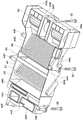
- FIG. 8 is an enlarged cross-sectional view of the indoor unit attached to the lower surface side of the footrest portion when viewed from the direction of arrows VIII-VIII in FIG. 7. It is the disassembled perspective view which looked at the state which isolate
- FIG. 14 It is the disassembled perspective view which looked at the state which isolate
- the box body of the indoor unit is formed as a closed structure body having a lower surface, a peripheral surface and an upper surface, and the indoor unit has the upper surface of the box body facing the unit mounting surface of the footrest portion.
- the configuration is such that it is mounted in a state.
- reference numeral 1 denotes a cab specification hydraulic excavator as a construction machine applied to the present embodiment.
- the hydraulic excavator 1 is a small excavator called a mini excavator suitable for work on a narrow work site.
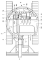
- the hydraulic excavator 1 includes a self-propelled lower traveling body 2, an upper revolving body 3 that is turnably mounted on the lower traveling body 2, and earth and sand provided in front of the upper revolving body 3 in the front and rear directions. And a work device 4 for performing the excavation work and the like.
- the upper turning body 3 has a left and right width dimension substantially equal to the vehicle width of the lower traveling body 2, and has a virtual turning radius R around the turning center O. It is formed in a substantially circular shape as seen from above so as to fit within the circle C.
- the excavator 1 has a rear surface in which the rear surface of the counterweight 36 (described later) is substantially within the vehicle width of the lower traveling body 2 when the upper revolving body 3 turns on the lower traveling body 2 around the turning center O. It is configured as a small swivel excavator.
- the turning radius R is defined by the distance from the turning center O to the rear surface of the counterweight 36, and the virtual circle C is a locus of the rear surface of the counterweight 36 when the upper swing body 3 is turned. Yes.
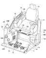
- the upper swing body 3 includes a swing frame 5, a floor member 9, a driver's seat 14, a cab box 17, an indoor unit 23, a bolt 32, an air conditioning duct 33, a counterweight 36, and the like, which will be described later.
- the turning frame 5 forms a support structure for the upper turning body 3 mounted on the lower traveling body 2.
- the working device 4 is attached to the front side of the revolving frame 5 so as to be swingable and capable of moving up and down.
- the engine 6 is mounted on the rear side of the revolving frame 5, and the engine 6 is disposed in a horizontally placed state extending in the left and right directions, for example.
- a heat exchange device 7 is provided on the right side of the engine 6 so as to face the cooling fan 6A, and a hydraulic pump 8 is provided on the left side.
- the heat exchange device 7 includes a radiator 7A connected to a water jacket 6B for cooling the engine 6, an oil cooler 7B for cooling hydraulic oil for driving various actuators, a condenser 21 of an outdoor unit 20 described later, and the like. It is comprised including.
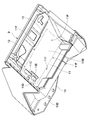
- the floor member 9 shows a floor member provided on the left side of the revolving frame 5.
- the floor member 9 is supported such that the front side position is tiltable to the front side position of the revolving frame 5, and the rear side position is supported on an upper portion of a counterweight 36 described later.
- the floor member 9 is tilted up (state shown in FIG. 3) and tilted down (state shown in FIG. 1) with the front position as a fulcrum together with the driver's seat 14, the cab box 17, the indoor unit 23, the air conditioning duct 33, and the like. be able to.
- a mounting plate 10D described later is supported on the counterweight 36 in a vibration-proof state.
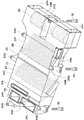
- the floor member 9 is roughly constituted by a driver seat mounting portion 10, a footrest portion 11 and a lever / pedal mounting portion 13 which will be described later.
- the driver seat mounting portion 10 is formed in a step shape on the rear side of the floor member 9, and the driver seat mounting portion 10 is for mounting a driver seat 14 described later.
- the driver seat mounting portion 10 includes a front plate 10A that extends upward from the rear portion of the footrest portion 11, and a substantially flat mounting plate 10B that extends rearward from the upper portion of the front plate 10A and mounts the driver seat 14 thereon.
- a back plate 10C extending upward from the rear portion of the mounting plate 10B, a mounting plate 10D extending from the upper portion of the back plate 10C to the rear side, and the mounting plate 10B and the back plate 10C from the front plate 10A.
- the left side plate 10 ⁇ / b> E extending rearward along the left end edge of the left side plate 10 ⁇ / b> E.
- the front plate 10A of the driver seat mounting portion 10 is located on the front side of the driver seat 14 and is, for example, an inside air filter (not shown) for removing dust in the inside air supplied to the indoor unit 23 described later. Is provided.
- an inner airflow inlet 10F for allowing the inside air to flow toward the inside air filter is provided at the front portion of the mounting plate 10B.
- the footrest portion 11 of the floor member 9 is provided on the front side of the driver seat mounting portion 10 by an operator who sits on the driver seat 14.
- the footrest portion 11 is formed as a substantially rectangular flat plate that is long in the left and right directions. That is, the footrest portion 11 has an upper surface 11A on which an operator's foot is placed, and a lower surface 11B to which an indoor unit 23 described later is attached.
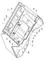
- three outlet mounting openings 11C, 11D, and 11E are provided on the right end side of the footrest portion 11 so as to extend in the front and rear directions.
- the outlet mounting opening 11C located on the front side is a room through which conditioned air that flows toward the operator seated on the front side of the driver's cab 18 and the driver's seat 14 flows out.
- a front air outlet 24J of the box body 24 of the unit 23 is disposed.
- a foot-side air outlet 24K that flows out conditioned air toward the operator's feet is disposed in the outlet mounting opening 11D located on the rear side of the outlet mounting opening 11C.
- a rear air outlet 24L through which conditioned air flows toward the rear side of the cab 18 is disposed in the outlet outlet opening 11E located on the left side of the outlet outlet opening 11D.
- the upper surface 11A of the footrest portion 11 has a plurality of female screw holes 11F into which bolts 32 to be described later for mounting the indoor unit 23 are screwed.
- a plurality of female screw holes 11F into which bolts 32 to be described later for mounting the indoor unit 23 are screwed.
- FIGS. Six locations are provided around 12.
- These six female screw holes 11F are arranged at positions corresponding to six bolt insertion holes 24G provided around the box body 24 described later.
- each female screw hole 11F is formed by, for example, welding a welding nut on a through hole formed in the footrest portion 11.
- the left end of the footrest portion 11 on the door 17F side of the cab box 17 described later is a step-shaped footrest portion 11G that the operator puts on when getting on and off the cab 18.
- the unit mounting surface 12 is provided on the lower surface 11B side of the footrest portion 11, and the unit mounting surface 12 is for mounting an indoor unit 23 described later. Specifically, the unit mounting surface 12 is provided in a range where the box body 24 of the indoor unit 23 abuts on the lower surface 11B of the footrest portion 11, that is, a range indicated by a two-dot chain line in FIG. The indoor unit 23 is directly attached to the unit attachment surface 12 in a suspended state so that the box body 24 faces the unit attachment surface 12.
- the lever / pedal attachment portion 13 is provided on the front side of the footrest portion 11, and the lever / pedal attachment portion 13 extends in the left and right directions along the front end of the footrest portion 11. As shown in FIG. 4, an operation lever / pedal 16 for traveling, which will be described later, is attached to the lever / pedal attaching portion 13.
- the driver's seat 14 is provided on the floor member 9, and the driver's seat 14 is placed at the left and right center positions of the placement plate 10 ⁇ / b> B constituting the driver seat mounting portion 10.
- the operator seat 14 is seated by an operator when the hydraulic excavator 1 is operated.
- work operation levers 15 for operating the work device 4 and the like are disposed on both the left and right sides of the driver's seat 14.
- the lever / pedal mounting portion 13 located in front of the driver's seat 14 is provided with an operation lever / pedal 16 for traveling that is operated by manual operation or stepping operation when the lower traveling body 2 is traveled.
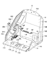
- the left side panel 17C which is the side surface of the cab box 17, is provided with a door 17F that can be opened and closed, located near the front side corresponding to the footrest portion 11 of the floor member 9. This door 17F opens and closes the entrance / exit provided on the left side of the footrest portion 11.
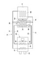
- the air conditioner 19 indicates an air conditioner used in the first embodiment.
- the air conditioner 19 includes an outdoor unit 20 provided on the engine 6 side, an indoor unit 23 provided on the floor member 9 side, and a refrigerant that connects the outdoor unit 20 and the indoor unit 23.
- the pipe 30 and the hot water pipe 31 are configured.
- the outdoor unit 20 is provided on the engine 6 side, and the outdoor unit 20 is disposed on the front side of the radiator 7A.
- the indoor unit 20 includes a condenser 21 that cools and liquefies the vaporized refrigerant, and a receiver dry 22 that is provided downstream of the condenser 21 and separates gas and liquid while temporarily storing the liquefied refrigerant.
- the radiator 7A of the heat exchange device 7 supplies hot water to a heater core 27 described later.
- the indoor unit 23 is provided on the upstream side of the box body 24 forming the outer shell and the box body 24, and the air sucked into the box body 24 is directed toward the air conditioning duct 33.
- the air supply switching mechanism 28 is configured to switch the supply destination of the conditioned air.
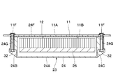
- the box body 24 of the indoor unit 23 is a box that forms a rectangular parallelepiped closed structure that is long in the left and right directions and flat in the lower and right directions in a rectangular shape extending in the left and right directions in plan view. It is formed as a body. That is, the box body 24 includes a rectangular lower surface portion 24A located at the bottom and extending left and right, and a front surface portion 24B and a rear surface portion 24C forming a peripheral surface extending upward from the periphery of the lower surface portion 24A.
- the left side surface portion 24D and the right side surface portion 24E, and the rectangular upper surface portion 24F extending in the left and right directions for closing the upper ends of the side surface portions 24B to 24E are roughly constituted.
- bolt insertion holes 24G as fastening member insertion holes are formed at six locations corresponding to the six female screw holes 11F of the footrest portion 11, and bolts 32 which will be described later are provided in the respective bolt insertion holes 24G. It is inserted.
- the upper surface portion 24F of the box body 24 faces the unit mounting surface 12 formed on the lower surface 11B of the footrest portion 11 in contact with or close to the unit mounting surface 12.
- the left side surface portion 24D located on the door 17F side of the cab box 17 is located on the upstream side in the air flow direction in the box body 24.
- the left side surface portion 24 ⁇ / b> D is provided with an air inlet 24 ⁇ / b> H for taking air into the box body 24.
- 24J, a foot side air outlet 24K, and a rear side air outlet 24L are provided on the downstream side of the box body 24 that is opposite to the left and right sides of the door 17F of the cab box 17, that is, on the right end side of the upper surface portion 24F.
- the front side air outlet 24J, the foot side air outlet 24K, and the rear side air outlet 24L extend upward in a frame shape so as to protrude above the upper surface 11A of the footrest portion 11.
- the front air outlet 24J located on the front side of the upper surface part 24F flows out conditioned air toward the operator seated on the front side of the cab 18 and the driver's seat 14, and is connected to a front supply duct 35A described later.
- the foot side air outlet 24K located on the rear side of the front side air outlet 24J flows out conditioned air toward the operator's feet, and is connected to a foot supply duct 35B described later.
- the rear side air outlet 24L located on the left side of the foot side air outlet 24K flows out conditioned air toward the rear side of the driver's seat 14, and is connected to a rear side supply duct 35C described later.
- the cooling fan 25 is provided on the upstream side (left side) in the box body 24, and the fan 25 circulates the air taken in from the air inlet 24H toward the air outlets 24J, 24K, and 24L.
- the evaporator 26 is accommodated in the box body 24, and the evaporator 26 is disposed in the vicinity of the downstream side (right side) of the fan 25.
- the evaporator 26 cools the air by using the heat of vaporization when the refrigerant is vaporized, and is connected to the condenser 21 of the outdoor unit, the receiver dryer 22 and the like via a refrigerant pipe 30 described later.
- the heater core 27 for heating is accommodated in the box body 24, and the heater core 27 is arranged in the vicinity of the downstream side (right side) of the evaporator 26.
- the heater core 27 warms air using engine cooling water warmed by the engine 6 and is connected to the radiator 7A via a hot water pipe 31 described later.
- the blowout switching mechanism 28 is located between the heater core 27 and the air outlets 24J, 24K, 24L and is accommodated in the box body 24.
- the blow switching mechanism 28 switches the air outlets 24J, 24K, and 24L to which conditioned air is supplied.
- the refrigerant pipe 30 connects the condenser 21 of the outdoor unit 20 and the evaporator 26 of the indoor unit 23.
- the hot water pipe 31 connects the radiator 7 ⁇ / b> A of the outdoor unit 20 and the heater core 27 of the indoor unit 23. As shown in FIG. 3, the refrigerant pipe 30 and the hot water pipe 31 are always connected even when the floor member 9 is tilted up, and are turned back at the front side position of the swivel frame 5 so as not to disturb the maintenance work. It extends like so.
- the bolt 32 is a plurality of bolts forming the fastening member, for example, six bolts.
- the bolt 32 is inserted into each bolt insertion hole 24G of the box body 24 from below, and the front end side of the bolt 32 is screwed into the female screw hole 11F of the footrest portion 11 so that the indoor unit 23 is attached to the lower surface of the footrest portion 11. It can be attached to 11B (unit attachment surface 12).
- the indoor unit 23 configured in this manner is brought into contact with the unit mounting surface 12 formed on the lower surface 11B of the footrest portion 11 of the floor member 9 from below.
- each bolt 32 inserted into each bolt insertion hole 24G of the box body 24 is screwed into the female screw hole 11F of the footrest portion 11.
- the indoor unit 23 can be directly attached to the unit attachment surface 12 using the bolt 32 in a suspended state.
- a foot outlet 34C that blows conditioned air toward the operator's feet is provided behind the front air outlet 34A. Further, on the rear side of the driver's seat 14, a rear outlet (not shown) is provided separately from the duct cover 34 for blowing conditioned air to the entire cab 18.
- the front supply duct 35A of the air conditioning duct 33 guides conditioned air from the indoor unit 23 to the front air outlet 34A and the driver seat side air outlet 34B.
- the foot supply duct 35B guides conditioned air from the indoor unit 23 to the foot outlet 34C.
- the rear supply duct 35C guides conditioned air from the indoor unit 23 to the rear outlet.
- the base end portion of the front supply duct 35 ⁇ / b> A constituting the air conditioning duct 33 is externally fitted to the front air outlet 24 ⁇ / b> J of the box body 24 of the indoor unit 23 protruding upward from the outlet mounting opening 11 ⁇ / b> C of the footrest portion 11. Installed in condition.
- the base end portion of the foot supply duct 35B is attached to the foot air outlet 24K of the box body 24 protruding upward from the outlet mounting opening 11D of the footrest portion 11 in an externally fitted state.
- the proximal end portion of the rear supply duct 35C is attached to the rear air outlet 24L of the box body 24 protruding upward from the outlet mounting opening 11E of the footrest portion 11 in an externally fitted state. Therefore, even when the footrest portion 11 is washed with water, it is possible to prevent the washing water from entering the outlets 24J, 24K, and 24L of the box body 24.
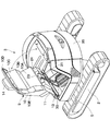
- 36 is a counterweight (see FIGS. 2 and 3) provided at the rear part of the revolving frame 5, and the counterweight 36 balances the weight with the work device 4.
- the counterweight 36 is formed in an arc shape so as to cover the engine 6 from the rear side. Further, the counterweight 36 constitutes a support structure for attaching the attachment plate 10D of the driver seat attachment portion 10 constituting the floor member 9 to the revolving frame 5 side.
- the hydraulic excavator 1 according to the first embodiment has the above-described configuration, and the operation thereof will be described next.
- the operation levers 15 for the left and right operations can be operated to perform soil excavation work and the like.
- the indoor unit 23 of the air conditioner 19 is driven in order to improve the environment in the cab 18.
- the indoor unit 23 sucks air inside or outside the cab 18 and cools this air with the evaporator 26 in the box body 24 or warms it with the heater core 27 to make conditioned air.
- the conditioned air can be blown to a desired position in the cab 18 and the cab 18 can be adjusted to an appropriate temperature.
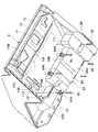
- the indoor unit 23 when performing maintenance work on the indoor unit 23, the indoor unit 23 can be exposed by tilting the rear side of the floor member 9 together with the driver's seat 14, the indoor unit 23, etc. with the front side as a fulcrum. Yes (see FIG. 3). In this state, by loosening the bolt 32, the indoor unit 23 can be removed and maintenance work can be performed.
- the footrest portion 11 of the floor member 9 since the footrest portion 11 of the floor member 9 only needs to be able to attach the indoor unit 23 to the unit attachment surface 12 on the lower surface 11B side using the bolt 32, it is not necessary to add special processing or parts. That is, the footrest portion 11 can be formed as a simple flat surface plate body in which only the female screw hole 11F is provided.
- the footrest portion 11 of the floor member 9 is not provided with an opening for disposing the indoor unit 23, so there is no need to provide a seal member for sealing the opening, and the interior of the cab 18 can be maintained. It is possible to reliably prevent water from being washed into the indoor unit 23 side. Thereby, when washing the inside of the cab 18 with water, it is not necessary to consider that the indoor unit 23 is splashed with water, so that the washing operation can be performed efficiently. Furthermore, it is possible to reduce the number of parts such as seal members, trays, lids, and the like and the man-hours for processing the footrests, which are necessary in the prior art.
- the footrest portion 11 of the floor member 9 is provided with outlet mounting openings 11C, 11D, and 11E located at the right back. Then, the outlets 24J, 24K, 24L of the box body 24 of the indoor unit 23 are attached to the outlet mounting openings 11C, 11D, 11E so as to protrude upward, and the outlets 24J, 24K,
- the supply ducts 35A, 28B, and 28C of the air conditioning duct 33 are attached to 24L in an externally fitted state. Thereby, even when the footrest portion 11 is washed with water, the washing water can be prevented from entering the outlets 24J, 24K, and 24L of the box body 24, and the life and reliability of the air conditioner 19 are improved. be able to.
- the floor member 9 can be tilted up and down with the front side position as a tilting fulcrum with respect to the revolving frame 5. Thereby, in a state where the floor member 9 is tilted up, the indoor unit 23 can be exposed to the outside, and attachment / detachment work, inspection work, repair work, and the like can be easily performed.
- FIG. 14 and FIG. 15 show a second embodiment of the present invention.
- the feature of this embodiment is that the box body of the indoor unit is formed in a frame-like structure with an open upper surface, and the unit mounting surface of the footrest portion closes the upper surface of the box body when the box body is mounted on the unit mounting surface. It is in the structure which forms the obstruction
- the same components as those in the first embodiment are denoted by the same reference numerals, and the description thereof is omitted.
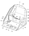
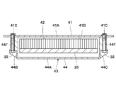
- reference numeral 41 denotes a footrest portion for the floor member according to the second embodiment.
- the footrest portion 41 is formed as a substantially rectangular flat plate that is long in the left and right directions, and the operator rests his / her foot in substantially the same manner as the footrest portion 11 according to the first embodiment described above. It has an upper surface 41A and a lower surface 41B to which an indoor unit 43 described later is attached.
- a plurality of female screw holes 41 ⁇ / b> C are provided on the upper surface 41 ⁇ / b> A of the footrest portion 41 to which the bolts 32 for attaching the indoor unit 43 are screwed.
- the indoor unit 43 indicates an indoor unit according to the second embodiment provided in the footrest portion 41. As shown in FIG. 15, the indoor unit 43 is roughly configured by a box body 44 that forms an outer shell, and a fan 25, an evaporator 26, a heater core 27, and a blow switching mechanism 28 provided in the box body 44. Yes.
- the box body 44 includes a rectangular lower surface portion 44A extending in the left and right directions, a front surface portion 44B, a rear surface portion 44C, and a peripheral surface extending upward from the periphery of the lower surface portion 44A.
- the left side surface portion 44D and the right side surface portion 44E are formed.
- the box body 44 is formed as a frame-like structure (box body) having a bottomed and upper surface opening with the upper side open and formed in a rectangular parallelepiped shape that is long in the left and right directions and flat in the upper and lower directions.
- the box body 44 is formed with bolt insertion holes 44F as fastening member insertion holes at positions corresponding to the respective female screw holes 41C of the footrest portion 41, and the bolts 32 are inserted into the respective bolt insertion holes 44F.
- An air inlet 44G for taking air into the box body 44 is provided on the left side surface portion 44D located on the upstream side which is the door 17F side of the cab box 17.
- a front side air outlet 44H, a foot side air outlet 44J, and a rear side air outlet 44K are provided on the upper right side which is the downstream side of the box body 44.
- the box body 44 has an open top surface, but is formed as a frame-like structure using the unit mounting surface 42 of the footrest portion 41 as the top surface portion. As a result, the box body 44 can be formed to have a smaller upper and lower dimensions by omitting the upper surface portion. In addition, the inspection and repair of the internal fan 25, evaporator 26, heater core 27, etc. can be performed simply by removing the box body 44 from the footrest portion 41.
- the box body 44 is brought into contact with the unit mounting surface 42 of the footrest portion 41 from below.
- each bolt 32 inserted into each bolt insertion hole 44 ⁇ / b> F of the box body 44 is screwed into the female screw hole 41 ⁇ / b> C of the footrest portion 41.
- the indoor unit 43 can be directly attached to the unit attachment surface 42 using the bolt 32 in a suspended state, and in this state, the upper opening of the box body 44 is connected to the unit attachment surface 42 (foot rest portion). 41).
- the box body 44 of the indoor unit 43 has a bottomed opening whose upper side is opened by the lower surface portion 44A and the front surface portion 44B, the rear surface portion 44C, the left surface portion 44D, and the right surface portion 44E.
- the box body 44 is configured to be attached to the unit mounting surface 42 of the footrest portion 41.
- the indoor unit 43 can use the unit mounting surface 42 of the footrest portion 41 as the upper surface portion of the box body 44.
- the height dimension of the indoor unit 43 (box body 44) can be reduced by an amount corresponding to the omission of the upper surface portion. Can be increased. Moreover, the accommodation space below the floor member 9 on the revolving frame 5 can be widened, and for example, equipment such as control valves can be efficiently arranged. Furthermore, when performing inspection work and repair work of the indoor unit 43, the internal fan 43, the evaporator 26, the heater core 27, and the like can be simply removed by removing the indoor unit 43 from the footrest portion 41 without disassembling the box body 44. Can be inspected and repaired, and workability can be improved.
- the present invention is not limited to this.
- a hydraulic excavator used at a work site where the temperature is low may be dedicated to heating by omitting the evaporator and providing only the heater core.
- a hydraulic excavator used at a work site with a high temperature may be exclusively used for cooling by omitting the heater core and providing only an evaporator. This configuration can be similarly applied to the second embodiment.
- the female screw holes 11F of the footrest portion 11 and the bolt insertion holes 24G of the box body 24 are provided at six locations, respectively, and the box body 24 is attached to the footrest portion 11 by the six bolts 32. It is configured to be installed.
- the present invention is not limited to this.
- the female screw hole 11F of the footrest portion 11 and the bolt insertion hole 24G of the box body 24 are provided at 5 or less or 7 or more, respectively, and the number of bolts corresponding to this is provided.
- the box body 24 may be attached to the footrest portion 11 by 32. This configuration can be similarly applied to the second embodiment.
- the cab specification hydraulic excavator 1 provided with the crawler type lower traveling body 2 was described as an example of the construction machine.
- the present invention is not limited to this, and may be applied to, for example, a hydraulic excavator provided with a wheel-type lower traveling body.
Landscapes
- Engineering & Computer Science (AREA)
- Mining & Mineral Resources (AREA)
- Civil Engineering (AREA)
- General Engineering & Computer Science (AREA)
- Structural Engineering (AREA)
- Mechanical Engineering (AREA)
- Physics & Mathematics (AREA)
- Thermal Sciences (AREA)
- Component Parts Of Construction Machinery (AREA)
- Air-Conditioning For Vehicles (AREA)
- Body Structure For Vehicles (AREA)
Priority Applications (5)
| Application Number | Priority Date | Filing Date | Title |
|---|---|---|---|
| KR1020137009103A KR101831390B1 (ko) | 2010-11-29 | 2011-10-20 | 건설기계 |
| JP2012546737A JP5341264B2 (ja) | 2010-11-29 | 2011-10-20 | 建設機械 |
| EP11845880.1A EP2647771B1 (de) | 2010-11-29 | 2011-10-20 | Baumaschine |
| CN201180051900.3A CN103189575B (zh) | 2010-11-29 | 2011-10-20 | 工程机械 |
| US13/819,146 US8967309B2 (en) | 2010-11-29 | 2011-10-20 | Construction machine |
Applications Claiming Priority (2)
| Application Number | Priority Date | Filing Date | Title |
|---|---|---|---|
| JP2010265080 | 2010-11-29 | ||
| JP2010-265080 | 2010-11-29 |
Publications (1)
| Publication Number | Publication Date |
|---|---|
| WO2012073611A1 true WO2012073611A1 (ja) | 2012-06-07 |
Family
ID=46171563
Family Applications (1)
| Application Number | Title | Priority Date | Filing Date |
|---|---|---|---|
| PCT/JP2011/074132 WO2012073611A1 (ja) | 2010-11-29 | 2011-10-20 | 建設機械 |
Country Status (6)
| Country | Link |
|---|---|
| US (1) | US8967309B2 (de) |
| EP (1) | EP2647771B1 (de) |
| JP (1) | JP5341264B2 (de) |
| KR (1) | KR101831390B1 (de) |
| CN (1) | CN103189575B (de) |
| WO (1) | WO2012073611A1 (de) |
Cited By (1)
| Publication number | Priority date | Publication date | Assignee | Title |
|---|---|---|---|---|
| US20140306488A1 (en) * | 2011-12-21 | 2014-10-16 | Hitachi Construction Machinery Co., Ltd. | Pilot Valve Attachment Structure of Construction Machine |
Families Citing this family (7)
| Publication number | Priority date | Publication date | Assignee | Title |
|---|---|---|---|---|
| NL2008634C2 (nl) * | 2012-04-13 | 2013-10-16 | Hudson Bay Holding B V | Mobiele inrichting. |
| JP5803981B2 (ja) * | 2013-06-07 | 2015-11-04 | コベルコ建機株式会社 | 建設機械のバルブ装置 |
| JP5949730B2 (ja) * | 2013-11-07 | 2016-07-13 | コベルコ建機株式会社 | 建設機械の電装品配設構造 |
| CN103741751A (zh) * | 2013-12-26 | 2014-04-23 | 柳州正菱集团有限公司 | 一种整体驾驶室的加工方法 |
| JP2016098592A (ja) * | 2014-11-25 | 2016-05-30 | キャタピラー エス エー アール エル | 建設機械のエアコンディショナ |
| US9708792B2 (en) * | 2015-04-27 | 2017-07-18 | Kobelco Construction Machinery Co., Ltd. | Construction machine having cooling function |
| DK178988B1 (en) * | 2015-12-15 | 2017-07-31 | Staal Ind Ivs | Selvkørende universalkøretøj |
Citations (6)
| Publication number | Priority date | Publication date | Assignee | Title |
|---|---|---|---|---|
| JP2004142663A (ja) * | 2002-10-25 | 2004-05-20 | Hitachi Constr Mach Co Ltd | 建設機械 |
| WO2004078562A1 (ja) * | 2003-03-04 | 2004-09-16 | Hitachi Construction Machinery Co., Ltd. | 建設機械 |
| JP2005330771A (ja) * | 2004-05-21 | 2005-12-02 | Kubota Corp | 旋回作業機 |
| JP2005330772A (ja) * | 2004-05-21 | 2005-12-02 | Kubota Corp | 旋回作業機 |
| JP2006002479A (ja) | 2004-06-18 | 2006-01-05 | Hitachi Constr Mach Co Ltd | 建設機械 |
| JP2007198057A (ja) * | 2006-01-27 | 2007-08-09 | Hitachi Constr Mach Co Ltd | 建設機械 |
Family Cites Families (19)
| Publication number | Priority date | Publication date | Assignee | Title |
|---|---|---|---|---|
| WO2000012826A1 (fr) * | 1998-08-31 | 2000-03-09 | Yanmar Diesel Engine Co., Ltd. | Machine de terrassement a tres petit pivotement |
| JP3702991B2 (ja) * | 1998-12-25 | 2005-10-05 | コベルコ建機株式会社 | 建設機械のキャブ |
| JP3681923B2 (ja) * | 1999-06-18 | 2005-08-10 | 株式会社クボタ | 旋回作業機 |
| JP3418361B2 (ja) * | 1999-08-19 | 2003-06-23 | 株式会社小松製作所 | 作業車両の運転室空気調和装置の取付構造 |
| JP4113925B2 (ja) * | 2000-01-19 | 2008-07-09 | ヤンマー株式会社 | バックホーのキャビン |
| EP1489234B1 (de) * | 2002-03-26 | 2012-02-29 | Kobelco Construction Machinery Co., Ltd. | Kleine schwenkschaufel |
| JP4072898B2 (ja) * | 2002-11-21 | 2008-04-09 | 株式会社小松製作所 | ハイブリッド式建設機械の機器配置構造 |
| WO2004076265A1 (ja) * | 2003-02-27 | 2004-09-10 | Komatsu Ltd. | 後端小旋回油圧ショベル |
| US7021074B2 (en) * | 2003-03-10 | 2006-04-04 | Kubota Corporation | Work vehicle |
| US7287810B2 (en) * | 2003-10-14 | 2007-10-30 | Hitachi Construction Machinery Co., Ltd. | Construction machine |
| JP4057542B2 (ja) * | 2004-02-04 | 2008-03-05 | 日立建機株式会社 | 建設機械 |
| JP4209787B2 (ja) * | 2004-02-26 | 2009-01-14 | 日立建機株式会社 | 建設機械 |
| EP1845205A4 (de) * | 2005-01-31 | 2013-01-02 | Komatsu Mfg Co Ltd | Arbeitsfahrzeug |
| EP1849688B1 (de) * | 2005-01-31 | 2011-06-15 | Komatsu Ltd. | Arbeitsfahrzeug mit kippboden |
| JP2008087530A (ja) * | 2006-09-29 | 2008-04-17 | Shin Caterpillar Mitsubishi Ltd | 建設機械における空調装置 |
| JP4880757B2 (ja) * | 2007-08-13 | 2012-02-22 | 日立建機株式会社 | 建設機械 |
| JP4472763B2 (ja) * | 2008-05-14 | 2010-06-02 | 株式会社アイメック | 建機車輌 |
| JP4952661B2 (ja) * | 2008-06-16 | 2012-06-13 | コベルコ建機株式会社 | 建設機械 |
| JP4976594B2 (ja) * | 2009-11-20 | 2012-07-18 | 日立建機株式会社 | 建設機械 |
-
2011
- 2011-10-20 CN CN201180051900.3A patent/CN103189575B/zh active Active
- 2011-10-20 KR KR1020137009103A patent/KR101831390B1/ko active IP Right Grant
- 2011-10-20 JP JP2012546737A patent/JP5341264B2/ja active Active
- 2011-10-20 EP EP11845880.1A patent/EP2647771B1/de active Active
- 2011-10-20 US US13/819,146 patent/US8967309B2/en active Active
- 2011-10-20 WO PCT/JP2011/074132 patent/WO2012073611A1/ja active Application Filing
Patent Citations (6)
| Publication number | Priority date | Publication date | Assignee | Title |
|---|---|---|---|---|
| JP2004142663A (ja) * | 2002-10-25 | 2004-05-20 | Hitachi Constr Mach Co Ltd | 建設機械 |
| WO2004078562A1 (ja) * | 2003-03-04 | 2004-09-16 | Hitachi Construction Machinery Co., Ltd. | 建設機械 |
| JP2005330771A (ja) * | 2004-05-21 | 2005-12-02 | Kubota Corp | 旋回作業機 |
| JP2005330772A (ja) * | 2004-05-21 | 2005-12-02 | Kubota Corp | 旋回作業機 |
| JP2006002479A (ja) | 2004-06-18 | 2006-01-05 | Hitachi Constr Mach Co Ltd | 建設機械 |
| JP2007198057A (ja) * | 2006-01-27 | 2007-08-09 | Hitachi Constr Mach Co Ltd | 建設機械 |
Cited By (1)
| Publication number | Priority date | Publication date | Assignee | Title |
|---|---|---|---|---|
| US20140306488A1 (en) * | 2011-12-21 | 2014-10-16 | Hitachi Construction Machinery Co., Ltd. | Pilot Valve Attachment Structure of Construction Machine |
Also Published As
| Publication number | Publication date |
|---|---|
| EP2647771B1 (de) | 2019-01-23 |
| KR101831390B1 (ko) | 2018-02-22 |
| EP2647771A1 (de) | 2013-10-09 |
| CN103189575B (zh) | 2015-06-10 |
| JPWO2012073611A1 (ja) | 2014-05-19 |
| EP2647771A4 (de) | 2017-10-04 |
| CN103189575A (zh) | 2013-07-03 |
| KR20140002626A (ko) | 2014-01-08 |
| JP5341264B2 (ja) | 2013-11-13 |
| US8967309B2 (en) | 2015-03-03 |
| US20130236281A1 (en) | 2013-09-12 |
Similar Documents
| Publication | Publication Date | Title |
|---|---|---|
| JP5341264B2 (ja) | 建設機械 | |
| JP4880757B2 (ja) | 建設機械 | |
| KR100646269B1 (ko) | 건설 기계 | |
| JP5758338B2 (ja) | 作業機 | |
| WO2013179694A1 (ja) | 旋回作業車 | |
| JP2006273055A (ja) | 旋回作業機 | |
| JP6823459B2 (ja) | 作業車両および運転室ユニット | |
| JP5384454B2 (ja) | 建設機械 | |
| JP4347730B2 (ja) | 建設機械 | |
| JP4291221B2 (ja) | 建設機械 | |
| JP6257541B2 (ja) | 建設機械 | |
| CA2805809A1 (en) | Under cab hvac cassete module | |
| JPH0762690A (ja) | 建設機械 | |
| JP5191189B2 (ja) | 旋回作業車 | |
| JPH11343636A (ja) | バックホーの冷房装置 | |
| JP2004268802A (ja) | 作業車 | |
| JP7391898B2 (ja) | 作業機 | |
| JP7443273B2 (ja) | 作業機 | |
| JP7326221B2 (ja) | 作業機 | |
| JP3124238B2 (ja) | 建設機械における空調装置 | |
| JP2013249622A (ja) | 建設機械 | |
| JP2004099041A (ja) | トラクタのエアコン取付装置 | |
| JP2003138600A (ja) | 建設機械 |
Legal Events
| Date | Code | Title | Description |
|---|---|---|---|
| 121 | Ep: the epo has been informed by wipo that ep was designated in this application |
Ref document number: 11845880 Country of ref document: EP Kind code of ref document: A1 |
|
| WWE | Wipo information: entry into national phase |
Ref document number: 2012546737 Country of ref document: JP |
|
| WWE | Wipo information: entry into national phase |
Ref document number: 13819146 Country of ref document: US |
|
| ENP | Entry into the national phase |
Ref document number: 20137009103 Country of ref document: KR Kind code of ref document: A |
|
| WWE | Wipo information: entry into national phase |
Ref document number: 2011845880 Country of ref document: EP |
|
| NENP | Non-entry into the national phase |
Ref country code: DE |