WO2012063765A1 - 非水電解質二次電池 - Google Patents
非水電解質二次電池 Download PDFInfo
- Publication number
- WO2012063765A1 WO2012063765A1 PCT/JP2011/075564 JP2011075564W WO2012063765A1 WO 2012063765 A1 WO2012063765 A1 WO 2012063765A1 JP 2011075564 W JP2011075564 W JP 2011075564W WO 2012063765 A1 WO2012063765 A1 WO 2012063765A1
- Authority
- WO
- WIPO (PCT)
- Prior art keywords
- phase
- negative electrode
- nano
- particles
- secondary battery
- Prior art date
- Legal status (The legal status is an assumption and is not a legal conclusion. Google has not performed a legal analysis and makes no representation as to the accuracy of the status listed.)
- Ceased
Links
Images


Classifications
-
- H—ELECTRICITY
- H01—ELECTRIC ELEMENTS
- H01M—PROCESSES OR MEANS, e.g. BATTERIES, FOR THE DIRECT CONVERSION OF CHEMICAL ENERGY INTO ELECTRICAL ENERGY
- H01M4/00—Electrodes
- H01M4/02—Electrodes composed of, or comprising, active material
- H01M4/36—Selection of substances as active materials, active masses, active liquids
- H01M4/38—Selection of substances as active materials, active masses, active liquids of elements or alloys
-
- B—PERFORMING OPERATIONS; TRANSPORTING
- B82—NANOTECHNOLOGY
- B82Y—SPECIFIC USES OR APPLICATIONS OF NANOSTRUCTURES; MEASUREMENT OR ANALYSIS OF NANOSTRUCTURES; MANUFACTURE OR TREATMENT OF NANOSTRUCTURES
- B82Y30/00—Nanotechnology for materials or surface science, e.g. nanocomposites
-
- B—PERFORMING OPERATIONS; TRANSPORTING
- B82—NANOTECHNOLOGY
- B82Y—SPECIFIC USES OR APPLICATIONS OF NANOSTRUCTURES; MEASUREMENT OR ANALYSIS OF NANOSTRUCTURES; MANUFACTURE OR TREATMENT OF NANOSTRUCTURES
- B82Y40/00—Manufacture or treatment of nanostructures
-
- H—ELECTRICITY
- H01—ELECTRIC ELEMENTS
- H01M—PROCESSES OR MEANS, e.g. BATTERIES, FOR THE DIRECT CONVERSION OF CHEMICAL ENERGY INTO ELECTRICAL ENERGY
- H01M10/00—Secondary cells; Manufacture thereof
- H01M10/05—Accumulators with non-aqueous electrolyte
- H01M10/052—Li-accumulators
-
- H—ELECTRICITY
- H01—ELECTRIC ELEMENTS
- H01M—PROCESSES OR MEANS, e.g. BATTERIES, FOR THE DIRECT CONVERSION OF CHEMICAL ENERGY INTO ELECTRICAL ENERGY
- H01M10/00—Secondary cells; Manufacture thereof
- H01M10/05—Accumulators with non-aqueous electrolyte
- H01M10/056—Accumulators with non-aqueous electrolyte characterised by the materials used as electrolytes, e.g. mixed inorganic/organic electrolytes
- H01M10/0564—Accumulators with non-aqueous electrolyte characterised by the materials used as electrolytes, e.g. mixed inorganic/organic electrolytes the electrolyte being constituted of organic materials only
- H01M10/0565—Polymeric materials, e.g. gel-type or solid-type
-
- H—ELECTRICITY
- H01—ELECTRIC ELEMENTS
- H01M—PROCESSES OR MEANS, e.g. BATTERIES, FOR THE DIRECT CONVERSION OF CHEMICAL ENERGY INTO ELECTRICAL ENERGY
- H01M10/00—Secondary cells; Manufacture thereof
- H01M10/05—Accumulators with non-aqueous electrolyte
- H01M10/056—Accumulators with non-aqueous electrolyte characterised by the materials used as electrolytes, e.g. mixed inorganic/organic electrolytes
- H01M10/0564—Accumulators with non-aqueous electrolyte characterised by the materials used as electrolytes, e.g. mixed inorganic/organic electrolytes the electrolyte being constituted of organic materials only
- H01M10/0566—Liquid materials
- H01M10/0567—Liquid materials characterised by the additives
-
- H—ELECTRICITY
- H01—ELECTRIC ELEMENTS
- H01M—PROCESSES OR MEANS, e.g. BATTERIES, FOR THE DIRECT CONVERSION OF CHEMICAL ENERGY INTO ELECTRICAL ENERGY
- H01M4/00—Electrodes
- H01M4/02—Electrodes composed of, or comprising, active material
- H01M4/13—Electrodes for accumulators with non-aqueous electrolyte, e.g. for lithium-accumulators; Processes of manufacture thereof
- H01M4/139—Processes of manufacture
- H01M4/1395—Processes of manufacture of electrodes based on metals, Si or alloys
-
- H—ELECTRICITY
- H01—ELECTRIC ELEMENTS
- H01M—PROCESSES OR MEANS, e.g. BATTERIES, FOR THE DIRECT CONVERSION OF CHEMICAL ENERGY INTO ELECTRICAL ENERGY
- H01M4/00—Electrodes
- H01M4/02—Electrodes composed of, or comprising, active material
- H01M4/36—Selection of substances as active materials, active masses, active liquids
- H01M4/38—Selection of substances as active materials, active masses, active liquids of elements or alloys
- H01M4/386—Silicon or alloys based on silicon
-
- Y—GENERAL TAGGING OF NEW TECHNOLOGICAL DEVELOPMENTS; GENERAL TAGGING OF CROSS-SECTIONAL TECHNOLOGIES SPANNING OVER SEVERAL SECTIONS OF THE IPC; TECHNICAL SUBJECTS COVERED BY FORMER USPC CROSS-REFERENCE ART COLLECTIONS [XRACs] AND DIGESTS
- Y02—TECHNOLOGIES OR APPLICATIONS FOR MITIGATION OR ADAPTATION AGAINST CLIMATE CHANGE
- Y02E—REDUCTION OF GREENHOUSE GAS [GHG] EMISSIONS, RELATED TO ENERGY GENERATION, TRANSMISSION OR DISTRIBUTION
- Y02E60/00—Enabling technologies; Technologies with a potential or indirect contribution to GHG emissions mitigation
- Y02E60/10—Energy storage using batteries
Definitions
- the present invention relates to a non-aqueous electrolyte secondary battery, and particularly to a non-aqueous electrolyte secondary battery having a high capacity and excellent cycle characteristics.
- Lithium ion secondary batteries are used mainly in portable devices, and higher capacities are required as the devices used become smaller and more multifunctional.
- carbon materials such as artificial graphite and natural graphite, which are currently used as negative electrode active materials for lithium ion secondary batteries, have a theoretical capacity of 372 mAh / g, and a further increase in capacity cannot be expected.
- a negative electrode using a metal material such as silicon (Si) or tin (Sn) having a larger theoretical capacity or an oxide material thereof has been proposed (for example, see Patent Document 1). Shows a very high capacity in the initial few cycles, but the pulverization due to expansion and contraction of the active material occurs due to repeated charge and discharge, and the negative electrode active material falls off the current collector, so the cycle characteristics are very poor. There was a problem.
- the method of suppressing deterioration by a charge / discharge cycle is mixed by mixing the component which can occlude Li, such as Si and Sn, and the components, such as Cu and Fe which do not occlude Li, by a mechanochemical method.
- the component which can occlude Li such as Si and Sn
- the components, such as Cu and Fe which do not occlude Li by a mechanochemical method.
- Patent Document 3 a method of forming a thin film of these materials on a current collector by a CVD method, a sputtering method, a vapor deposition method, or a plating method has been proposed. Furthermore, as a method for stabilizing the coating on the electrode surface formed by this method, a method of adding a cyclic carbonate having an unsaturated bond to the electrolytic solution has been proposed (for example, Patent Document 4).
- the negative electrode active material layer is formed by a CVD method, a sputtering method, a vapor deposition method, or a plating method
- deterioration in cycle characteristics can be suppressed to some extent. Since only a thin film electrode having a thin negative electrode active material layer can be formed, and the amount of active material is insufficient to constitute a lithium secondary battery, practical application is difficult.
- the invention described in Patent Document 4 can suppress deterioration of cycle characteristics by forming a strong film on the surface of the active material layer of the thin film electrode and suppressing decomposition of the electrolytic solution.
- the conventional coating-type electrode in which the active material layer is formed by the method cannot obtain the suppressing effect.
- the present invention has been made in view of the above-mentioned problems, and an object of the present invention is to obtain a nonaqueous electrolyte secondary battery that realizes a high capacity and good cycle characteristics.
- the present inventor has found that the pulverization of the negative electrode active material can be suppressed by using a nano-sized negative electrode active material mainly having lithium storage properties. Furthermore, it discovered that the 1st phase which occludes lithium, and the 2nd phase which does not occlude lithium are joined via an interface, and can suppress the volume expansion of the 1st phase by charging / discharging.
- the negative electrode active material layer is obtained by including an organic substance capable of reduction polymerization having an unsaturated bond in the electrolyte.
- the present invention provides the following inventions.
- a positive electrode capable of inserting and extracting lithium ions a negative electrode capable of inserting and extracting lithium ions, and a separator disposed between the positive electrode and the negative electrode, and having lithium ion conductivity
- a non-aqueous electrolyte secondary battery in which the positive electrode, the negative electrode, and the separator are provided in an aqueous electrolyte, wherein the negative electrode active material of the negative electrode includes first particles containing an element X and an element M And the element X is one element selected from the group consisting of Si, Sn, Al, Pb, Sb, Bi, Ge, In, and Zn, and the element M is: And at least one element selected from the group consisting of Group 4 to 11 transition metal elements, wherein the first particles are composed of a single element or a solid solution of the element X, and the second particles are Consisting of a simple element or a compound of element M, Liquid is non-aqueous electrolyte secondary battery,
- the negative electrode active material of the negative electrode is composed of nano-sized particles containing the element X and the element M
- the element X is one element selected from the group consisting of Si, Sn, Al, Pb, Sb, Bi, Ge, In, and Zn
- the element M is a transition metal of group 4 to 11 At least one element selected from the group consisting of elements, wherein the nano-sized particles are a first phase that is a single element or a solid solution of the element X, and a second phase that is a single element or a compound of the element M.
- a nonaqueous electrolyte secondary battery characterized by reducing polymerizing an unsaturated bond in the molecule contains organic matter as possible.
- the nano-sized particles have both the first phase and the second phase exposed on the outer surface, and are bonded via an interface.
- the nonaqueous electrolyte secondary battery according to (4) which is substantially spherical.
- the nano-sized particles include Cu, Fe, Co, Ni, Ca, Sc, Ti, V, Cr, Mn, Sr, Y, Zr, Nb, Mo, Tc, Ru, Rh, Ba, and a lanthanoid element ( Further including an element M ′, which is at least one element selected from the group consisting of Hf, Ta, W, Re, Os, and Ir, and the element M ′ includes the second phase.
- an element M ′ which is at least one element selected from the group consisting of Hf, Ta, W, Re, Os, and Ir
- the non-water according to (4) wherein the element M is a different element from the element M and further includes another second phase that is a single element or a compound of the element M ′.
- Electrolyte secondary battery Electrolyte secondary battery.
- the nano-sized particles further include an element X ′ that is at least one element selected from the group consisting of Si, Sn, Al, Pb, Sb, Bi, Ge, In, and Zn, and the element X
- the nonaqueous electrolyte secondary battery according to (4) further comprising a third phase which is a simple substance or a solid solution.
- the organic substance having an unsaturated bond in the molecule and capable of reductive polymerization is at least one selected from the group consisting of fluoroethylene carbonate, vinylene carbonate and derivatives thereof, and vinyl ethylene carbonate.
- the amount of the organic substance having an unsaturated bond in the molecule and capable of reductive polymerization is 0.1 wt% to 10 wt% of the electrolyte weight, Water electrolyte secondary battery.
- the negative electrode is formed by applying a coating liquid containing at least a negative electrode active material, a conductive material, and a binder to a current collector and drying it (1) or (4) The non-aqueous electrolyte secondary battery described in 1.
- a non-aqueous electrolyte secondary battery that realizes a high capacity and good cycle characteristics can be obtained.
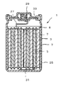
- the cross-sectional schematic diagram which shows an example of the nonaqueous electrolyte secondary battery which concerns on this invention.
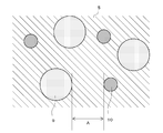
- the conceptual diagram which shows an example of a structure of the negative electrode active material which concerns on 1st Embodiment.
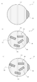
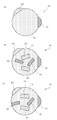
- (A)-(c) is a schematic sectional drawing of the nanosized particle which concerns on 2nd Embodiment.
- (A), (b) is a schematic sectional drawing of the nanosized particle which concerns on 2nd Embodiment.
- (A), (b) is a schematic sectional drawing of the nanosized particle which concerns on 2nd Embodiment.
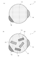
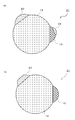
- A)-(c) is a schematic sectional drawing of the nanosized particle which concerns on 3rd Embodiment.
- FIG. (A), (b) is a schematic sectional drawing of the nanosized particle which concerns on 3rd Embodiment.
- the nonaqueous electrolyte secondary battery 1 of the present invention includes a positive electrode 3 capable of inserting and extracting lithium ions, a negative electrode 5 capable of inserting and extracting lithium ions, and a separator 7 disposed between the positive electrode 3 and the negative electrode 5.
- the positive electrode 3, the negative electrode 5, and the separator 7 are provided in a non-aqueous electrolyte solution 8 having lithium ion conductivity.
- the negative electrode 5 uses, as an active material, particles made of an element that easily occludes lithium ions having a characteristic configuration, and the electrolyte 8 used corresponding to this negative electrode is unsaturated in the molecule. It contains an organic substance having a bond and capable of reductive polymerization.
- FIG. 2 is a conceptual diagram showing an example of the configuration of the negative electrode active material.
- the negative electrode active material includes first particles 9 containing the element X and second particles 10 containing the element M.
- the first particles 9 may be composed of the element X alone or a solid solution containing the element X as a main component.
- the element X is one element selected from the group consisting of Si, Sn, Al, Pb, Sb, Bi, Ge, In, and Zn.
- the phrase “having element X as the main component” means that the proportion of element X is 50 atomic% or more, more preferably 70 atomic% or more.
- the first particle 9 is a solid solution of the element X
- the element that forms a solid solution with the element X can be selected from the elements listed in the group of the element X, but is selected from the other elements. be able to.
- the element X is an element that easily stores lithium, and the first particles 9 can also store lithium.
- grains 9 can be made into a substantially spherical shape fundamentally, and the aspect of various other forms is mentioned later.
- the element X is preferably Si from the viewpoint of the occlusion characteristics of lithium ions.
- the conductivity of silicon can be increased by adding phosphorus or boron to silicon. Indium and gallium can be used instead of phosphorus, and arsenic can be used instead of boron.
- the second particles 10 may be composed of the element M alone or a compound containing the element M as a main component.
- the element M is at least one element selected from the group consisting of Group 4 to 11 transition metal elements of the periodic table.
- the element M is stable. Elements such as Ti, V, Cr, Mn, Fe, Co, Ni, Cu, Zr, Nb, Mo, Ru, Rh, Pd, Ag, Hf, Ta, W, Re, Os, Ir, Pt, Au, etc.
- These elements M are elements that do not easily store lithium.
- the element that forms a compound with the element M is not particularly limited, but may be the element X described above.
- the second particles 10 hardly exhibit lithium storage characteristics, but the lithium storage characteristics can be adjusted by the ratio of the element M and the elements forming the compound.
- the compound can include various alloys, intermetallic compounds, oxides, and the like.
- the second particle 10 is composed of a single element or a compound of the element M, two or more electrons exist in the d electron orbit.
- the outermost electron configuration of Ti, Fe, and Ni is Ti: 3d [2] 4S [2], Fe: 3d [6] 4S [2], Ni: 3d [8] 4S [2], d
- the electron orbit has 2, 6, and 8 electrons, respectively.
- an organic substance having an unsaturated bond in the molecule and capable of reductive polymerization is contained in the nonaqueous electrolyte solution 8 described later due to its electronic interaction.
- the first particles 9 and the second particles 10 are the surfaces of the closest first particles 9 and the second particles 10 indicated by A in FIG.
- the distance is set to be within 1 ⁇ m.
- the distance A within 1 ⁇ m is a range in which the interaction of electrons at the interface between the first particle 9 and the second particle 10 reaches, and is a distance of about the thickness of the electric double layer.
- electrons are supplied to the element M of the second particle 10, thereby having an unsaturated bond in the molecule contained in the non-aqueous electrolyte solution 8.
- An organic polymer is produced that is capable of reductive polymerization.
- the first particles are more stable than those produced by the second particles in addition to the coating by the reduction product produced on the surface of the first particles.
- the reduction product is adsorbed on the surface of the first particles and covers the surface, so that the decomposition of the electrolyte is suppressed.
- the average particle diameter of the first particles 9 is preferably 2 nm to 500 nm, more preferably 2 nm to 300 nm, and further 50 nm to 200 nm. According to Hall Petch's law, the yield stress increases when the particle size is small. Therefore, if the average particle size of the nano-sized particles is about 2 nm to 500 nm, the particle size is small, the yield stress is large, and it is difficult to pulverize by charge / discharge. When the average particle size is smaller than 2 nm, it is difficult to handle nano-sized particles after synthesis. When the average particle size is larger than 500 nm, the particle size is too large to obtain a sufficient yield stress, which is not preferable.
- One second particle 10 does not need to consider the influence of pulverization, so the average particle size can be 2 nm to 10 ⁇ m.
- the lower limit is 2 nm because it is a guide value that is not difficult to handle as in the case of the first particles 9 described above, and the upper limit is 10 ⁇ m because the electrode active material is applied to the current collector. This is because the density of the active material is uneven when the cycle characteristics are deteriorated.
- the second particle 10 becomes too large, the surface area per unit weight is reduced and the catalytic action is also reduced, so that a large amount of the second particle 10 is required to obtain the effect, It is preferable that the particle size of the second particles 10 is small in that the weight of the entire battery is increased.
- the ratio of the second particles 10 to the first particles 9 can be arbitrarily set within a range in which a desired lithium occlusion amount can be secured by the first particles 9, As a rough guide, it is preferably 1% to 30%, more preferably 7% to 10%, based on the number of X atoms constituting the first particle 9. If the atomic ratio is less than 1%, the effect of forming a film on the surface of the negative electrode and the effect of suppressing the volume change of the negative electrode due to charge / discharge cannot be sufficiently obtained. When the atomic ratio is more than 30%, a sufficient amount of lithium occlusion may not be ensured.
- the negative electrode active material has the second particles 10 containing the element M having a high conductivity in addition to the first particles 9 having a relatively low conductivity, the conductivity of the negative electrode 5 as a whole jumps. Rises. That is, even if there is little conductive auxiliary agent, it is a negative electrode active material which has electroconductivity, can form a high capacity
- a highly conductive metal element such as Fe or Cu as the second particles 10
- a negative electrode active material having better conductivity can be obtained compared to the case of using only silicon nanoparticles.
- the first particles 9 in addition to the first particles 9, the first particles 9 also include second particles.
- the first particles 9 expand when they occlude lithium, whereas the second particles 10 occlude lithium. Therefore, the volume change as the whole negative electrode can be suppressed. Thereby, even if lithium is occluded, the distortion accompanying the volume expansion of the negative electrode is alleviated, and the reduction of the discharge capacity during the cycle characteristics is suppressed.
- FIG. 3 is a schematic cross-sectional view showing the nano-sized particles 11 constituting the negative electrode active material of the negative electrode 5 of the present invention.
- the nano-sized particle 11 includes an element X and an element M.
- the element X is one element selected from the group consisting of Si, Sn, Al, Pb, Sb, Bi, Ge, In, and Zn.
- the element X is an element that easily stores lithium.
- the element M is at least one element selected from the group consisting of Group 4 to 11 transition metal elements.
- the element M is a stable element. Specifically, Ti, V, Cr, Mn, Fe, Co, Ni, Cu, Zr, Nb, Mo, Ru, Rh, Pd, Ag, Hf, Ta, W, Re, Os, Ir, Pt, Au, etc. It is.
- These elements M are elements that do not easily store lithium.
- the nanosized particle 11 in this invention has the 1st phase 13 and the 2nd phase 15 at least.
- the first phase 13 may be a single element X or a solid solution containing Si as a main component. Further, the first phase 13 may be crystalline or amorphous.
- the element that forms a solid solution with the element X can be selected from elements other than those listed in the group of the element X.
- the first phase 13 can occlude lithium.
- the first phase 13 becomes amorphous when occluded by lithium and alloyed and then desorbed and dealloyed.
- the second phase 15 may be a simple substance of the element M or a compound containing the element M as a main component.
- the second phase 15 hardly absorbs lithium.
- the element M since the element M has two or more electrons in the d electron orbit as described above, the formation of a film that protects the negative electrode 5 can be promoted and cycle characteristics can be improved.
- the second phase 15 may be formed of MX Y , which is a compound of the element X and the element M, or the like.
- the second phase 15 may be a single element or a solid solution of the element M.
- the second phase 15 can be formed of copper silicide that is a compound of the element M and the element X.
- the second phase 15 can be formed of a single element of the element M or a solid solution containing the element M as a main component.
- Si and element M can form a compound represented by MX Y (1 ⁇ Y ⁇ 3).
- the atomic ratio of the element M to the total of Si and the element M is preferably 0.01 to 25%. When the atomic ratio is 0.01 to 25%, both the cycle characteristics and the high capacity can be achieved when the nano-sized particles 11 are used as the negative electrode active material. On the other hand, if it is less than 0.01%, the volume change at the time of occlusion of lithium of the nano-sized particles 11 cannot be suppressed, and if it exceeds 25%, the merit of high capacity is particularly lost.
- the nano-sized particles 11 are exposed to the outer surface of the nano-sized particles 11 and both the first phase 13 and the second phase 15 are bonded to each other through the interface. is doing.
- the interface between the first phase 13 and the second phase 15 is a flat surface or a curved surface. Further, the interface may be stepped.
- the first phase 13 has a substantially spherical outer surface.
- the interface shape of the joint portion between the first phase 13 and the second phase 15 is circular or elliptical.
- the outer surface of the first phase 13 has a substantially spherical shape means that the surface of the first phase 13 other than the interface where the first phase 13 and the second phase 15 are in contact is generally a smooth curved surface. In other words, it means that the first phase 13 has a spherical shape or an elliptical spherical shape except for the point where the first phase 13 and the second phase 15 are in contact with each other.
- the expression “sphere” or “elliptical sphere” does not mean a geometrically exact sphere or ellipsoid. The shape is different from the shape having a corner on the surface, as represented by the shape of particles formed by the crushing method.
- the second phase 15 that is a simple substance or a compound of the element M may be dispersed in the first phase 13 like the nano-sized particles 11 shown in FIG.
- the second phase 15 is covered with the first phase 13.
- the second phase 15 hardly absorbs lithium.
- a part of the second phase 15 covered with the first phase 13 may be exposed on the surface. That is, the entire periphery of the second phase 15 is not necessarily covered with the first phase 13, and only a part of the periphery of the second phase 15 may be covered with the first phase 13.
- a plurality of second phases 15 are dispersed in the first phase 13, but a single second phase 15 may be included.
- the second phase 15 ′ shown in FIG. 4 (a) it may have a polyhedral shape due to the influence of the element M or the stability of the crystal of the compound.
- a plurality of second phases 15 may be provided on the first phase 13 like the nano-sized particles 11 shown in FIG.
- the ratio of the element M is small, the collision frequency between the elements M in the gas state or the liquid state is low, the relationship between the melting points of the first phase 13 and the second phase 15 and wetting. It is conceivable that the second phase 15 is dispersed and joined to the surface of the first phase 13 due to the property, the influence of the cooling rate, and the like.
- the area of the interface between the first phase 13 and the second phase 15 is widened to further suppress the expansion and contraction of the first phase 13. Can do.
- the second phase 15 since the second phase 15 has a higher conductivity than the first phase 13, the movement of electrons is promoted by the second phase 15, and the nanosize particles 11 are collected in each nanosize particle 11. It will have an electric spot. Therefore, the nano-sized particles 11 having a plurality of second phases 15 become a negative electrode material having high powder conductivity, can reduce the conductive auxiliary agent, and can form a high capacity negative electrode. Furthermore, a negative electrode having excellent high rate characteristics can be obtained.
- the second phase 15 that is a compound of one element M and the element X includes another element.
- M may be contained as a solid solution or a compound. That is, even when two or more elements selected from the group from which the element M can be selected are contained in the nano-sized particles, the other second phase 19 is not formed unlike the element M ′ described later.
- the element X is Si
- one element M is Ni
- the other element M is Fe
- Fe may exist in NiSi 2 as a solid solution.
- the distribution of Ni and the distribution of Fe may be approximately the same or different, and another element M may be uniformly contained in the second phase 15. For example, it may be partially contained.
- the nano-sized particles may contain the element M ′ in addition to the element M.
- Element M ′ includes Cu, Fe, Co, Ni, Ca, Sc, Ti, V, Cr, Mn, Sr, Y, Zr, Nb, Mo, Tc, Ru, Rh, Ba, lanthanoid elements (Ce and Pm Except), at least one element selected from the group consisting of Hf, Ta, W, Re, Os, and Ir, and an element of a different type from the element M constituting the second phase.
- the nano-sized particle 17 shown in FIG. 5A includes the element M and the element M ′, and has another second phase 19 in addition to the second phase 15 that is a simple substance or a compound of the element M.
- the nano-sized particle 17 has two small spheres joined to the surface of a large sphere. Can have a shape.
- the other second phase 19 is a simple substance or a compound of the element M ′ and, like the second phase 15, hardly absorbs lithium.
- the nano-sized particles 17 may include a solid solution (not shown) composed of the element M and the element M ′.
- the second phase 15 is a compound of Si and Fe
- the other second phase 19 is a compound of Si and Co
- the solid solution composed of the elements M and M ′ is a solid solution of Fe and Co. Etc.
- the second phase 15 that is a simple substance or a compound of the element M and another second phase 19 that is a simple substance or a compound of the element M ′ are included in the first phase 13. It may be dispersed in the inside.
- FIGS. 5A and 5B show an example in which two types of elements are selected from the group of elements from which the element M and the element M ′ can be selected, but even when three or more types of elements are selected. Good.
- the group of the element M and the element M ′ with respect to the total of the elements of the group of the element X, the element M, and the element M ′.
- the total atomic ratio of these elements is preferably 0.01 to 30%.
- the first phase 13 is mainly crystalline silicon and the second phase 15 is crystalline silicide.
- the first phase 13 is more preferably Si to which phosphorus or boron is added.
- the conductivity of silicon can be increased by adding phosphorus or boron. Indium and gallium can be used instead of phosphorus, and arsenic can be used instead of boron.
- the negative electrode using such nano-sized particles has a low internal resistance, allows a large current to flow, and has a good high-rate characteristic.
- the average particle size of the nano-sized particles 11 and 17 and 21 described later is preferably 2 to 500 nm, more preferably 50 to 200 nm.
- the yield stress increases when the particle size is small. If the average particle size of the nano-sized particles is 2 to 500 nm, the particle size is sufficiently small, the yield stress is sufficiently large, and it is difficult to pulverize by charge / discharge. . When the average particle size is smaller than 2 nm, it is difficult to handle nano-sized particles after synthesis. When the average particle size is larger than 500 nm, the particle size becomes large and the yield stress is not sufficient.
- the average particle size of the nano-sized particles here refers to the average particle size of the primary particles.
- image information of an electron microscope (SEM) and a volume-based median diameter of a dynamic light scattering photometer (DLS) are used in combination.
- SEM electron microscope
- DLS dynamic light scattering photometer
- the average particle size confirm the particle shape in advance using an SEM image, obtain the particle size by image analysis (for example, “A Image-kun” (registered trademark) manufactured by Asahi Kasei Engineering), or disperse the particles in a solvent to obtain DLS (for example, , DLS-8000 manufactured by Otsuka Electronics Co., Ltd.).
- the average particle size is defined by the primary particle size here, and the average particle size is obtained by image analysis of the SEM photograph. be able to.
- oxygen may be bonded to the outermost surface of the nano-sized particles 11 or 17. This is because when the nano-sized particles are taken out into the air, oxygen in the air reacts with elements on the surface of the nano-sized particles.
- the outermost surface of the nano-sized particles 11 or 17 may have an amorphous layer having a thickness of about 0.5 to 15 nm.
- the oxide film layer You may have.
- the second phase 15 containing the element M is included in addition to the first phase 13 that occludes lithium, the second phase 15 of the second phase 15 is similar to the first embodiment. Due to the catalytic action, a stable organic film can be effectively formed on the surface of the negative electrode active material layer, decomposition of the electrolyte material can be prevented, and cycle characteristics can be improved.
- the first phase 13 occludes lithium
- the volume expands, but the second phase 15 does not occlude lithium, and therefore the expansion of the first phase 13 in contact with the second phase 15 is suppressed. That is, even if the first phase 13 occludes lithium and tries to expand its volume, the second phase 15 hardly expands, so that the second phase 15 exhibits an effect like a wedge or a pin, and is nanosized. Swelling of the entire particle 11 or 17 is suppressed. Therefore, compared with particles not having the second phase 15, the nano-sized particles 11 or 17 having the second phase 15 are less likely to expand when occlusion of lithium, and the restoring force works when lithium is released. It becomes easy to return to the shape of. Therefore, according to the present invention, even when lithium is occluded in the nano-sized particles 11 or 17, distortion associated with volume expansion is relieved, and a decrease in discharge capacity during cycle characteristics is suppressed.
- the nano-sized particles 11 or 17 are difficult to expand, even if the nano-sized particles are put out into the atmosphere, they hardly react with oxygen in the atmosphere.
- nanosized particles having only one phase are left in the atmosphere without surface protection, they react with oxygen from the surface, and oxidation proceeds from the surface to the inside of the particles. Oxidize.
- the nano-sized particles 11 or 17 of the present invention are left in the atmosphere, the outermost surface of the particles reacts with oxygen, but since the nano-sized particles are difficult to expand as a whole, oxygen is less likely to enter the interior. Oxidation hardly reaches the center of the size particle.
- the nano-sized particles 11 or 17 of the present invention need to be specially coated with an organic substance or metal oxide. And can be handled as powder in the atmosphere. Such features have great industrial utility value.
- the conductivity of the nano-sized particles 11 or 17 as a whole increases dramatically.
- the nano-sized particles 11 or 17 are equivalent to a structure in which each nano-sized particle has a nano-level current collecting spot, and become a negative electrode material having conductivity even if there is a small amount of conductive auxiliary agent.
- a capacitor electrode can be formed, and can be a negative electrode active material having excellent high-rate characteristics.
- a highly conductive metal element such as Fe or Cu for the second phase 15
- a negative electrode active material with better conductivity can be obtained as compared to the case of using only silicon nanoparticles.
- the nano-sized particles 11 including the second phase 15 in the first phase 13 and the nano-sized particles 17 including the second phase 15 and another second phase 19 in the first phase 13 are: More parts of the first phase 13 are in contact with a phase that does not occlude lithium, and the expansion of the first phase 13 is more effectively suppressed.
- the nano-sized particles 17 can exhibit the effect of suppressing volume expansion with a small amount of the element M, and can effectively increase the amount of element X such as Si that can occlude lithium, Capacity and cycle characteristics are improved.
- the nano-sized particles 17 having both the second phase 15 exposed to the outer surface and the other second phase 19 have the same effect as described above, and the number of nano-level current collection spots is increased. Effectively improve. Addition of two or more elements M and element M 'group generates two or more compounds, and these compounds are easy to separate from each other, so different compounds are easy to separate, increasing the current collection spot It is easy to do and is more preferable.
- FIG. 6 is a schematic cross-sectional view of the nanosized particles 21 constituting the negative electrode active material of the negative electrode 5 of the present invention.
- the nano-sized particles 21 have a third phase 23 in addition to the same first phase 13 and second phase 15 as described above.
- the third phase 23 includes an element X ′ that is at least one element selected from the group consisting of Si, Sn, Al, Pb, Sb, Bi, Ge, In, and Zn, and is different from the element X Elements. These elements X ′ are elements that easily store lithium.
- the third phase 23 may be a single element X ′ or a solid solution containing the element X ′ as a main component.
- the element that forms a solid solution with the element X ′ may be an element selected from the group capable of selecting the element X ′, or may be an element not listed in the group.
- the third phase 23 can occlude lithium.
- the first phase 13, the second phase 15, and the third phase 23 are all exposed on the outer surface, and the outer surfaces of the first phase 13, the second phase 15, and the third phase 23 are substantially spherical. It may be a shape.
- the second phase 15 is bonded to the first phase 13, and the third phase 23 is bonded to at least one of the first phase 13 and the second phase 15 through an interface.
- the interface between the third phase 23 and the first phase 13 is a flat surface or a curved surface.
- the 2nd phase 15 and the 3rd phase 23 may join via the interface.
- the first phase 13 is Si
- the second phase 15 is a compound of Si and Fe.
- the third phase 23 is Sn.
- the second phase 15 that is a single element or a compound of the element M and the third phase 23 that is a single element or a solid solution of the element X ′ It may be dispersed in the phase 13. Further, a phase (not shown) which is a compound of the element X ′ and the element M may be dispersed. These phases 15 and 23 are covered by the first phase 13, but some of the phases 15 and 23 may be exposed on the surface as shown in FIG. That is, it is not always necessary to cover all of the periphery of the phases 15 and 23 dispersed in the first phase 13 with the first phase 13, and only a part of the periphery is covered with the first phase 13. Also good. Note that a plurality of phases may be dispersed in the first phase 13, for example, any of the second phase 15, the third phase 23, and a phase that is a compound of the element X ′ and the element M. May be dispersed.
- the shape of the surface other than the interface of the third phase 23 may be a spherical surface whose surface is generally smooth like the third phase 23 shown in FIG. 6A, or FIG. As shown in the third phase 23 ′ shown in FIG.
- the polyhedron shape is formed by peeling after the nano-sized particles 11, 17 or 21 are bonded through the third phase 23.
- the 1st phase 13 and the 3rd phase 23 can suppress the site
- oxygen is included, the capacity decreases, but volume expansion accompanying lithium occlusion can be suppressed.
- Amount of oxygen z is, for example XO z, when a X'O z, 0 ⁇ z ⁇ 1 is preferably in the range.
- z is 1 or more, the Li storage sites of the element X and the element X ′ are suppressed, and the capacity is greatly reduced.
- the atomic ratio of the element M and the element M ′ in the total is 0.01 to 25% for the same reason as above. It is preferable to set the degree. When the atomic ratio is 0.01 to 25%, both the cycle characteristics and the high capacity can be achieved when the nano-sized particles 21 are used as the negative electrode active material.
- the nano-sized particle 21 can further contain two or more kinds of elements X ′.
- the second element X ′ is one element selected from the group of the elements X ′ and is a different kind of element from the first element X ′.
- silicon can be used as the element X
- tin and aluminum can be used as the element X ′.
- the element X ′ may form another third phase as a simple substance or a solid solution, or may form a compound with the element M and the element M ′.
- the other third phase has a spherical outer surface and can be exposed on the outer surface of the nano-sized particles 21.
- a phase that is a compound of the element X ′ and the element M may be dispersed in the first phase 13 or the third phase 23.
- the nano-sized particles 21 may contain an element M ′ in addition to the element M.
- the nano-sized particles 21 are composed of various combinations of compounds and solid solution phases from various combinations of the elements X, X ′, the element M, and the element M ′. Can be included. Such a phase may be exposed on the surface of the nano-sized particle 21 or may be dispersed in the first phase 13 or any other phase.
- oxygen may be bonded to the outermost surface of the nano-sized particles 21. This is because when the nanosize particles 21 are taken out into the air, oxygen in the air reacts with elements on the surface of the nanosize particles 21.
- the outermost surface of the nano-sized particles 21 may have an amorphous layer having a thickness of about 0.5 to 15 nm.
- the oxide layer is provided. You may do it.
- volume expansion occurs when the first phase 13 occludes lithium, and expansion also occurs when the third phase 23 occludes lithium.
- the electrochemical potential for storing lithium differs between the first phase 13 and the third phase 23
- grains 21 which have the 1st phase 13 and the 3rd phase 23 are hard to expand
- negative electrode active material As the negative electrode active material according to the present invention, as the first particles 9 in the negative electrode active material A, nano-sized particles of the negative electrode active materials B and C may be used. By doing in this way, also in the negative electrode active material A, the effect similar to the negative electrode active materials B and C can be acquired.
- the negative electrode active material according to the present invention at least a part of the surfaces of the first particles 9 and the nano-sized particles 11, 17, and 21 in the negative electrode active materials A to C described above can be used, for example, copper, tin, Those coated with zinc, silver, nickel or carbon can also be considered.
- the thickness of the coating is exemplified to be in the range of 0.01 to 0.5 ⁇ m.
- Cu is selected as the element M ′
- the other second phase 19 that is a single element M ′ is the first phase 13. It can also be understood that the first phase 13 and the second phase 15 are not presently bonded (not shown).
- the conductivity of the entire negative electrode is improved and cycle characteristics are also improved without using a conductive aid or the like. Further, since the surface of the negative electrode active material is coated, oxidation of silicon or the like can be suppressed. By covering the surface, resistance to volume changes due to charge / discharge is improved.
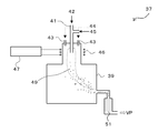
- Nano-sized particles can be synthesized by a gas phase synthesis method.
- nano-sized particles can be produced by converting the raw material powder into plasma and heating it to the equivalent of 10,000 K, followed by cooling.
- a high frequency coil 46 for generating plasma is wound around the upper outer wall of the reaction chamber 39.
- An AC voltage of several MHz is applied to the high frequency coil 46 from a high frequency power source 47.
- a preferred frequency is 4 MHz.
- the upper outer wall around which the high-frequency coil 46 is wound is a cylindrical double tube made of quartz glass or the like, and cooling water is passed through the gap to prevent the quartz glass from melting by plasma.
- a sheath gas supply port 43 is provided in the upper part of the reaction chamber 39 together with the raw material powder supply port 41.
- the raw material powder 42 supplied from the raw material powder feeder is supplied into the plasma 49 through the raw material powder supply port 41 together with the carrier gas 45 (rare gas such as helium and argon).
- the sheath gas 44 is supplied to the reaction chamber 39 through the sheath gas supply port 43.
- the raw material powder supply port 41 is not necessarily installed above the plasma 49 as shown in FIG. 8, and a nozzle can be installed in the lateral direction of the plasma 49.
- the raw material powder supply port 41 may be water-cooled with cooling water.
- the property of the raw material of the nanosize particles supplied to the plasma is not limited to the powder, and a slurry of the raw material powder or a gaseous raw material may be supplied.
- the reaction chamber 39 plays a role of maintaining the pressure in the plasma reaction part and suppressing the dispersion of the produced fine powder.
- the reaction chamber 39 is also water-cooled to prevent damage due to plasma.
- a suction tube is connected to the side of the reaction chamber 39, and a filter 51 for collecting the synthesized fine powder is installed in the middle of the suction tube.
- the suction pipe connecting the reaction chamber 39 and the filter 51 is also water-cooled with cooling water.
- the pressure in the reaction chamber 39 is adjusted by the suction capability of a vacuum pump VP (not shown) installed on the downstream side of the filter 51.
- the method for producing nano-sized particles is a bottom-up method in which a nano-sized particle is deposited from plasma into a solid via a gas and a liquid, so that it becomes spherical at the droplet stage, and the first phase 13 and the second phase are formed.
- the phase 15 has a spherical shape.
- the shape of the particles is rugged and is significantly different from the spherical shape of the nano-sized particles 11.
- the nanosized particle 11 which concerns on 2nd Embodiment is obtained.
- the nano-sized particles 17 according to the second embodiment are obtained.
- the nano-sized particles 21 according to the second embodiment are obtained.
- the method for coating the surface of the particles is not particularly limited, and various known methods can be employed. Electroless plating or displacement plating is used for coating the metal, and the surface oxidation of particles such as silicon is small, and electroplating is possible if the particles are conductive.
- a method of heat treatment in an inert or reducing atmosphere after mixing an inorganic carbon source such as carbon black or an organic carbon source such as polyvinyl alcohol can be used.
- a thermal decomposition CVD method in which the surface of particles is coated with carbon by heating the hydrocarbon gas to 600 ° C. or higher to be thermally decomposed can also be used.
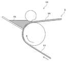
- the negative electrode of the present invention can be formed by applying a coating liquid containing at least a negative electrode active material, a conductive material and a binder to a current collector and drying it.
- the coating liquid can be prepared by charging a slurry raw material 57 into a mixer 53 and kneading to form a slurry (coating liquid) 55.
- the slurry raw material 57 is nano-sized particles, a conductive aid, a binder, a thickener, a solvent, and the like.
- the solid content in the slurry 55 is, for example, a blend of 25 to 90% by weight of nano-sized particles, 5 to 70% by weight of a conductive aid, 1 to 30% by weight of a binder, and 0 to 25% by weight of a thickener. can do.
- the mixer 53 may be a general kneader used for slurry preparation, and may be an apparatus capable of preparing a slurry called a kneader, a stirrer, a disperser, a mixer, or the like.
- a thickener it is suitable to use polysaccharides, such as carboxymethylcellulose and methylcellulose, as a 1 type, or 2 or more types of mixture.
- water can be used as a solvent.
- N-methyl-2-pyrrolidone can be used as a solvent.
- the conductive assistant is a powder made of at least one conductive material selected from the group consisting of carbon, copper, tin, zinc, nickel, silver and the like.
- a single powder of carbon, copper, tin, zinc, nickel, or silver may be used, or a powder of each alloy may be used.
- general carbon black such as furnace black and acetylene black can be used.
- carbon nanohorns can be added as conductive aids.
- the element X of the nano-sized particles is silicon having low conductivity, silicon is exposed on the surface of the nano-sized particles, and the conductivity is lowered. Therefore, carbon nanohorn may be added as a conductive auxiliary agent. preferable.
- the carbon nanohorn has a structure in which a graphene sheet is rounded into a conical shape, and the actual form is an aggregate in the form of a radial sea urchin with many CNHs facing the apex to the outside.
- the outer diameter of the sea urchin-like aggregate of CNH is about 50 nm to 250 nm.
- CNH having an average particle size of about 80 nm is preferable. Any one of these materials may be used, or two or more of these materials may be used in combination.
- the average particle size of the conductive auxiliary agent also refers to the average particle size of the primary particles. Even when the structure shape is highly developed such as acetylene black, the average particle diameter can be defined by the primary particle diameter here, and the average particle diameter can be obtained by image analysis of the SEM photograph.
- both a particulate conductive aid and a wire-shaped conductive aid may be used.
- the wire-shaped conductive aid is a wire made of a conductive material, and the conductive materials listed in the particulate conductive aid can be used.
- As the wire-shaped conductive assistant a linear body having an outer diameter of 300 nm or less, such as carbon fiber, carbon nanotube, copper nanowire, or nickel nanowire, can be used.
- VGCF vapor grown carbon fiber
- the length of the wire-shaped conductive assistant is preferably 0.1 ⁇ m to 2 mm.
- the outer diameter of the conductive aid is preferably 4 nm to 1000 nm, more preferably 25 nm to 200 nm. If the length of the conductive auxiliary agent is 0.1 ⁇ m or more, the length is sufficient to increase the productivity of the conductive auxiliary agent, and if the length is 2 mm or less, application of the slurry is easy. Further, when the outer diameter of the conductive auxiliary agent is larger than 4 nm, the synthesis is easy, and when the outer diameter is thinner than 1000 nm, the slurry is easily kneaded. The measuring method of the outer diameter and length of the conductive material was performed by image analysis using SEM.
- the binder is a resin binder, fluorine resin such as polyvinylidene fluoride (PVdF), synthetic rubber such as styrene butadiene rubber (SBR), acrylic resin, celluloses such as carboxymethyl cellulose, polyimide, polyamide An organic material such as imide can be used. Any one of these materials may be used, or two or more of these materials may be used in combination.
- fluorine resin such as polyvinylidene fluoride (PVdF)
- SBR styrene butadiene rubber
- acrylic resin celluloses such as carboxymethyl cellulose
- polyimide polyimide
- polyamide polyamide
- An organic material such as imide can be used. Any one of these materials may be used, or two or more of these materials may be used in combination.
- NMP N-methyl-2-pyrrolidone
- a slurry 55 is applied to one surface of the current collector 61 using a coater 59.
- a coater 59 a general coating apparatus capable of applying the slurry 55 to the current collector 61 can be used.
- the coater 59 is a coater, a comma coater, or a die coater using a roll coater or a doctor blade.
- the current collector 61 is a foil made of at least one metal selected from the group consisting of copper, nickel, and stainless steel. Each metal may be used independently and may be used as each alloy.
- the thickness is preferably 4 ⁇ m to 35 ⁇ m, more preferably 8 ⁇ m to 18 ⁇ m.
- a negative electrode for a non-aqueous electrolyte secondary battery can be obtained through a roll press.
- polyimide or polyamideimide it is preferable to perform heat treatment in the range of 250 ° C to 450 ° C.
- This positive electrode for a lithium ion battery is prepared by mixing a positive electrode active material, a conductive additive, a binder and a solvent to prepare a positive electrode active material composition, which is directly applied onto a metal current collector such as an aluminum foil. -It can be manufactured by drying.
- Any positive electrode active material can be used as long as it is generally used.
- LiCoO 2 , LiMn 2 O 4 , LiMnO 2 , LiNiO 2 , LiCo 1/3 Ni 1/3 Mn 1/3 O 2 , compounds such as LiFePO 4 are exemplified.
- carbon black is used as the conductive assistant
- PVdF polyvinylidene fluoride
- NMP N-methyl-2-pyrrolidone
- Water, etc. can be used.
- the contents of the positive electrode active material, the conductive additive, the binder, and the solvent are at levels normally used in non-aqueous electrolyte secondary batteries and the like.
- Any separator can be used as long as it has a function of insulating electronic conduction between the positive electrode and the negative electrode and is usually used in a non-aqueous electrolyte secondary battery.
- a microporous polyolefin film can be used.
- Electrolyte / Electrolyte As the electrolytic solution and the electrolyte, a non-aqueous organic electrolytic solution having lithium ion conductivity used for a lithium ion secondary battery, a Li polymer battery, or the like can be used.
- organic electrolyte solvent examples include carbonates such as ethylene carbonate, propylene carbonate, butylene carbonate, diethyl carbonate, dimethyl carbonate, and methyl ethyl carbonate; diethyl ether, dibutyl ether, ethylene glycol dimethyl ether, ethylene glycol diethyl ether, ethylene glycol di Ethers such as butyl ether and diethylene glycol dimethyl ether; aprotic such as benzonitrile, acetonitrile, tetrahydrofuran, 2-methyltetrahydrofuran, ⁇ -butyrolactone, dioxolane, 4-methyldioxolane, N, N-dimethylformamide, dimethylacetamide, dimethylchlorobenzene, nitrobenzene Solvent, or two of these solvents Mixed solvent of the above can be cited.
- carbonates such as ethylene carbonate, propylene carbonate, butylene carbonate, diethyl carbonate, dimethyl
- the electrolyte of the organic electrolyte includes LiPF 6 , LiClO 4 , LiBF 4 , LiAlO 4 , LiAlCl 4 , LiSbF 6 , LiSCN, LiCl, LiCF 3 SO 3 , LiCF 3 CO 3 , LiC 4 F 9 SO 3 , LiN (CF 3 SO 2 )
- a mixture of one or more electrolytes made of a lithium salt such as 2 can be used.
- the electrolyte is characterized by containing an organic substance having an unsaturated bond in the molecule and capable of reductive polymerization.
- an organic substance having an unsaturated bond in the molecule and capable of undergoing reductive polymerization at the time of charging include, for example, carbonates such as fluoroethylene carbonate, vinylene carbonate (VC), vinyl ethylene carbonate, and derivatives thereof, and unsaturated carboxylic acid esters.
- VC vinylene carbonate
- vinyl ethylene carbonate vinyl ethylene carbonate
- derivatives thereof unsaturated carboxylic acid esters.
- Phosphoric acid esters, boric acid esters, alcohols and the like can be used. Among them, it is shown as a preferable example that vinylene carbonate (VC) is used.
- Such an organic substance is preferably added in an amount of about 0.1 to 10% by weight of the electrolyte weight in order to obtain a stable solid electrolyte interface coating. Further, it is more preferable to add about 1 to 5% by weight.
- the addition amount is in the range of 0.1% by weight to 10% by weight, it can be reduced during charging to form a stable film on the surface of the negative electrode active material layer, and the decomposition of the electrolyte material can be prevented. .
- the addition amount is less than 0.1% by weight, it is difficult to sufficiently form a stable film on the surface of the negative electrode active material, and when the addition amount exceeds 10% by weight, it is reduced. Since the amount increases, the formed solid electrolyte interface film becomes thick, and the impedance of the battery increases, which is not preferable.
- a separator is disposed between the positive electrode and the negative electrode as described above to form a battery structure. After winding or folding such a battery structure into a cylindrical or rectangular battery case, an electrolyte is injected to complete a lithium ion secondary battery.
- a positive electrode 3 and a negative electrode 5 are laminated in the order of separator-negative electrode-separator-positive electrode with a separator 7 interposed therebetween. Then, the positive electrode 3 is wound so as to be on the inner side to form an electrode plate group, which is inserted into the battery can 25.
- the positive electrode 3 is connected to the positive electrode terminal 29 via the positive electrode lead 27, and the negative electrode 5 is connected to the battery can 25 via the negative electrode lead 31, and the chemical energy generated inside the nonaqueous electrolyte secondary battery 1 is externally used as electric energy. To be able to take out.
- the upper end (opening portion) of the battery can 25 is composed of a circular lid plate and a positive electrode terminal 29 on the upper portion thereof.
- the non-aqueous electrolyte secondary battery 1 of the present invention can be manufactured by attaching the sealing body 33 having a built-in safety valve mechanism thereto via an annular insulating gasket.
- the non-aqueous electrolyte secondary battery according to the present invention uses nano-sized particles containing Si, which has a higher capacity per unit volume than carbon, as a negative electrode active material, and therefore has a larger capacity than a conventional lithium ion secondary battery.
- the cycle characteristics are good because the nano-sized particles are not easily pulverized.
- the surface of the negative electrode active material layer can be stabilized by including an organic substance capable of reduction polymerization having an unsaturated bond in the electrolyte. Effective film is formed, the negative electrode active material is stabilized, decomposition of the electrolytic solution is suppressed, and cycle characteristics are improved.
- the silicon and iron nano-sized particles were manufactured by continuously supplying the plasma with a carrier gas.
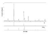
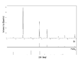
- FIG. 11 shows an XRD diffraction pattern of the nano-sized particles of Example 1.
- the nano-sized particles obtained in Example 1 were found to be composed of two components, Si and FeSi 2 . It was also found that all Fe was present as silicide FeSi 2 and there was almost no Fe as a single element (valence 0).
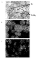
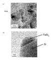
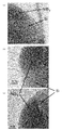
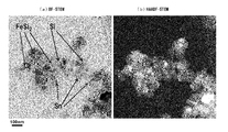
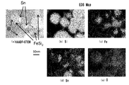
- FIG. 12A is a BF-STEM (Bright-Field Scanning Transmission Electron Microscope, bright-field scanning transmission electron microscope) image of nano-sized particles according to Example 1.
- FIG. Nano-sized particles in which hemispherical particles are bonded to the substantially spherical particles having a particle size of about 80 to 100 nm via the interface are observed, and within the same particles, a relatively dark colored portion is iron containing iron. It is made of silicide, and a relatively light-colored portion is made of silicon.
- FIG. 12B is a STEM photograph by HAADF-STEM (High-Angle-Annular-Dark-Field-Scanning-Transmission-Electron-Microscopy: high angle scattering dark field-scanning transmission electron microscopy).
- HAADF-STEM High-Angle-Annular-Dark-Field-Scanning-Transmission-Electron-Microscopy: high angle scattering dark field-scanning transmission electron microscopy.
- HAADF-STEM High-Angle-Annular-Dark-Field-Scanning-Transmission-Electron-Microscopy: high angle scattering dark field-scanning transmission electron microscopy.
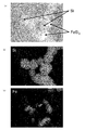
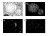
- FIG. 13 (a) is a HAADF-STEM image of nano-sized particles
- FIG. 13 (b) is an EDS map of silicon atoms at the same observation location
- FIG. 13 (c) is an illustration at the same observation location. It is an EDS map of an iron atom.
- nano-sized particles having a particle size of about 50 to 150 nm are observed, and each nano-sized particle has a substantially spherical shape.
- silicon atoms are present in the entire nano-sized particles, and from FIG. 13 (c), many iron atoms are detected at the brightly observed positions in FIG. 13 (a). From the above, it can be seen that nano-sized particles have a structure in which a second phase formed of a compound of silicon and iron is bonded to a first phase formed of silicon.
- the charge / discharge characteristics were evaluated by measuring the initial discharge capacity and the discharge capacity after 50 cycles of charge / discharge, and determining the ratio of the discharge capacity after 50 cycles of charge / discharge to the initial discharge capacity as a percentage.
- the discharge capacity is the weight of the active material Si (Si and Sn if Sn is included) that is effective for lithium insertion / extraction, excluding silicon and tin that do not occlude / release lithium, such as forming silicide. Calculated as a reference. First, in a 25 ° C. environment, constant current charging was performed at a current of 0.1 C to a voltage of 0.02 V, and constant voltage charging was performed until the current value decreased to 0.05 C.
- FIG. 16 shows an XRD diffraction pattern of the nano-sized particles according to Example 2.
- Example 2 was found to be composed of two components of Si and FeSi 2. It was also found that all Fe was present as silicide FeSi 2 and there was almost no elemental Fe. In comparison with FIG. 9, as compared to the nano-sized particles according to Example 1, small proportions of Fe, a peak derived from FeSi 2 can not be confirmed only a trace amount.
- FIG. 17A The observation result by STEM is shown in FIG. According to FIG. 17A, a large number of substantially spherical particles having a diameter of about 50 to 150 nm are observed. In the non-overlapping particles, it is considered that the dark part is iron silicide and the light part is silicon. Further, it is observed that the atoms of the silicon portion are regularly arranged, and it can be seen that the silicon corresponding to the first phase is crystalline.
- FIG. 17B shows that the surface of the nano-sized particles is covered with an amorphous layer having a thickness of about 1 nm on the silicon portion, and the amorphous layer having a thickness of about 2 nm is covered on the portion of iron silicide. Moreover, by comparing the STEM photographs in FIG. 12 and FIG. 17, the relative sizes of Si and FeSi 2 can be confirmed, and the FeSi 2 of the nano-sized particles according to Example 2 is the same as that of the nano-sized particles according to Example 1. It can be seen that it is smaller than FeSi 2
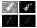
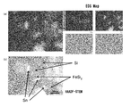
- FIGS. 18 (a) The observation of particle shape by HAADF-STEM and the results of EDS analysis are shown in FIGS.
- FIG. 18 (a) nano-sized particles having a particle size of about 150 to 250 nm are observed, and each nano-sized particle has a substantially spherical shape.
- FIG. 18B it can be seen that silicon atoms are present in the entire nano-sized particle, and from FIG. 18C, a large amount of iron atoms are detected at the bright spots observed in FIG.
- FIG. 18 (d) it can be seen that oxygen atoms considered to be due to oxidation are slightly distributed throughout the nano-sized particles.
- nano-sized particles having a particle diameter of about 250 nm are observed, and from FIG. 19B, silicon atoms are present in the entire nano-sized particles, and FIG. From c), it can be seen that many iron atoms are detected in the brightly observed part in FIG. From FIG. 19 (d), it can be seen that oxygen atoms considered to be due to oxidation are slightly distributed throughout the nano-sized particles. From the above, it can be seen that nano-sized particles have a structure in which a second phase formed of a compound of silicon and iron is bonded to a first phase formed of silicon.
- FIG. 20 shows an XRD diffraction pattern of the nano-sized particles according to Example 3.
- Example 3 was found to be composed of two components of Si and NiSi 2. Further, it was found that Ni was present as silicide NiSi 2 and there was almost no Ni as a single element (valence 0). It can be seen that Si and NiSi 2 have the same diffraction angle 2 ⁇ and almost the same plane spacing.
- FIG. 21 (a) is a BF-STEM image
- FIG. 21 (b) is a HAADF-STEM image with the same field of view.
- nano-sized particles having a particle size of about 75 to 150 nm are observed.
- Each nano-sized particle is bonded to a large particle having a substantially spherical shape, and another particle having a substantially hemispherical shape is bonded via an interface. It has a shape like this.
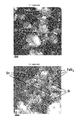
- FIG. 22 is a high-resolution TEM image of nanosized particles according to Example 3.
- FIGS. 22A to 22C lattice images are seen, and the lattice stripes of the silicon phase and the silicide phase almost coincide with each other, indicating that the silicide has a polyhedral shape.
- the boundary between the silicon phase and the silicide phase is a straight line, a curve, or a staircase. It can also be seen that the surface of the nano-sized particles is covered with an amorphous layer of silicon having a thickness of about 2 nm.
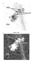
- FIG. 23 shows the HAADF-STEM image of the nano-sized particles according to Example 3 and the results of EDS analysis.
- FIG. 23 (a) nano-sized particles having a particle size of about 75 to 150 nm are observed.
- FIG. 23B it can be seen that silicon atoms are present in the entire nano-sized particles, and from FIG. 23C, a large amount of nickel atoms are detected at the brightly observed positions in FIG.
- the nano-sized particles have a structure in which a second phase formed of a compound of silicon and nickel is bonded to a first phase formed of silicon.
- FIG. 23 (d) shows that oxygen atoms considered to be oxidized are slightly distributed throughout the nano-sized particles.
- FIG. 24 is an X-ray diffraction (XRD) pattern of nano-sized particles according to Example 4. Nano-sized particles according to Example 4 is seen to have a Si, Sn, and FeSi 2.
- FIGS. STEM photographs of nanosized particles according to Example 4 are shown in FIGS. Nano-sized particles having a substantially spherical outer surface with a particle size of about 50 to 150 nm were observed. In FIG. 25A, it is considered that the dark part is Sn and the light part is Si.
- Nano-sized particles having a substantially spherical outer surface with a particle size of about 50 to 150 nm were observed.
- the bright area is mainly composed of Sn
- the dark area is mainly composed of Si.
- FIG. 27 (a) nano-sized particles having a particle size of about 100 to 150 nm are observed, and from FIG. 27 (b), a large number of silicon atoms are detected in the darkly observed locations in FIG. I understand. From FIG. 27 (c), it can be seen that many iron atoms are detected at locations that are observed slightly brighter in FIG. 27 (a). From FIG. 27 (d), it can be seen that many tin atoms are detected at the bright spots observed in FIG. 27 (a). From FIG. 27 (e), it can be seen that oxygen atoms that are thought to be due to oxidation are distributed throughout the nano-sized particles.
- FIG. 28 is a diagram further showing the EDS analysis results.
- FIG. 28A is a diagram in which an EDS map of Fe and Sn and these are superimposed
- FIG. 28B is a HAADF-STEM image in the same field of view. According to Fig.28 (a), there is little overlap of the detection point of Sn and Fe. In the XRD analysis, no peak derived from the Sn—Fe alloy was confirmed, and therefore no Sn—Fe alloy was formed on the nanosized particles. Moreover, since Si and Sn do not form an alloy, Sn exists alone.
- FIG. 29 is a diagram showing the EDS analysis results at the first to third locations in the nano-sized particles.
- Si was mainly observed and Sn was slightly observed.
- Si and Sn were observed at the second location in FIG.
- Si and Fe were mainly observed, and a slight amount of Sn was observed.
- the background of Cu derived from the TEM mesh holding the sample during observation is widely observed.
- Example 1 As the negative electrode active material, instead of the nano-sized particles, silicon nanoparticles having an average particle size of 100 nm (made by Hefei Kai'er NanoTech) were used, and the negative electrode E was manufactured and evaluated in the same manner as in Example 1. A cell was constructed and the charge / discharge characteristics were examined.
- Example 2 The negative electrode A prepared in the same manner as in Example 1 was used as a test electrode, lithium as a counter electrode and a reference electrode, a microporous membrane made of polyolefin as a separator, and ethylene carbonate (EC) containing 1.3 mol / L LiPF 6 as an electrolyte. ), Ethyl methyl carbonate (EMC), and a mixed solution of dimethyl carbonate (DMC) were used to form an evaluation cell, and the charge / discharge characteristics were examined. That is, vinylene carbonate (VC) was not added to the electrolytic solution.
- EMC Ethyl methyl carbonate
- DMC dimethyl carbonate
- Example 3 A negative electrode B produced in the same manner as in Example 2 was used as a test electrode, and thereafter, an evaluation cell was constructed in the same manner as in Comparative Example 2, and the charge / discharge characteristics were examined.
- Example 4 A negative electrode C prepared in the same manner as in Example 3 was used as a test electrode, and thereafter, an evaluation cell was constructed in the same manner as in Comparative Example 2, and the charge / discharge characteristics were examined.
- Example 5 A negative electrode D prepared in the same manner as in Example 4 was used as a test electrode, and thereafter, an evaluation cell was constructed in the same manner as in Comparative Example 2, and the charge / discharge characteristics were examined.
- Comparative Example 6 A negative electrode E produced in the same manner as in Comparative Example 1 was used as a test electrode, and thereafter, an evaluation cell was constructed in the same manner as in Comparative Example 2, and the charge / discharge characteristics were examined.
- Table 2 shows the discharge capacities and capacity retention rates of Examples 1 to 4 and Comparative Examples 1 to 6.
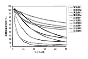
- FIG. 30 shows the relationship between the number of cycles in Examples 1 to 4 and Comparative Examples 1 to 6 and the discharge capacity retention rate.
- the effect of suppressing the decrease in capacity by adding VC to the electrolytic solution can be suitably obtained as described above for the nonaqueous electrolyte secondary battery according to the present invention.
- the non-aqueous electrolyte secondary battery using Si nano-sized particles as the negative electrode active material has no effect at all, but rather has reduced charge / discharge characteristics.
- Fe and Ni were used as the negative electrode active material as an element M that forms a second phase with a compound with Si, and Sn was used as an element A that forms a third phase.
- the negative electrode active material is not limited to this. Any nano-sized particles including at least a first phase made of Si and a second phase of a compound MSi X (1 ⁇ X ⁇ 3) of the elements M and Si may be used.
- Fe and Ni for example, Ti It is presumed that similar results can be obtained even when Co or Co is used.
- vinylene carbonate was used as an organic substance having an unsaturated bond in the molecule and capable of reductive polymerization, but it has an unsaturated bond in the molecule that can be used in the present invention and can be reductively polymerized.
- the organic material is not limited to this. It is presumed that the result of the same tendency as in the present example can be obtained even if vinyl ethylene carbonate is used, for example, by performing reductive polymerization at the negative electrode charging potential and forming a stable film on the negative electrode active material surface.
Landscapes
- Chemical & Material Sciences (AREA)
- Engineering & Computer Science (AREA)
- Chemical Kinetics & Catalysis (AREA)
- Electrochemistry (AREA)
- General Chemical & Material Sciences (AREA)
- Manufacturing & Machinery (AREA)
- Nanotechnology (AREA)
- Condensed Matter Physics & Semiconductors (AREA)
- General Physics & Mathematics (AREA)
- Physics & Mathematics (AREA)
- Inorganic Chemistry (AREA)
- Crystallography & Structural Chemistry (AREA)
- Materials Engineering (AREA)
- Dispersion Chemistry (AREA)
- Composite Materials (AREA)
- Battery Electrode And Active Subsutance (AREA)
- Secondary Cells (AREA)
Priority Applications (2)
| Application Number | Priority Date | Filing Date | Title |
|---|---|---|---|
| KR1020137012990A KR101520557B1 (ko) | 2010-11-08 | 2011-11-07 | 비수 전해질 2차 전지 |
| CN201180053949.2A CN103222092B (zh) | 2010-11-08 | 2011-11-07 | 非水电解质二次电池 |
Applications Claiming Priority (2)
| Application Number | Priority Date | Filing Date | Title |
|---|---|---|---|
| JP2010-250223 | 2010-11-08 | ||
| JP2010250223A JP5520782B2 (ja) | 2010-11-08 | 2010-11-08 | 非水電解質二次電池 |
Publications (1)
| Publication Number | Publication Date |
|---|---|
| WO2012063765A1 true WO2012063765A1 (ja) | 2012-05-18 |
Family
ID=46050911
Family Applications (1)
| Application Number | Title | Priority Date | Filing Date |
|---|---|---|---|
| PCT/JP2011/075564 Ceased WO2012063765A1 (ja) | 2010-11-08 | 2011-11-07 | 非水電解質二次電池 |
Country Status (5)
| Country | Link |
|---|---|
| JP (1) | JP5520782B2 (enExample) |
| KR (1) | KR101520557B1 (enExample) |
| CN (1) | CN103222092B (enExample) |
| TW (1) | TWI437746B (enExample) |
| WO (1) | WO2012063765A1 (enExample) |
Cited By (3)
| Publication number | Priority date | Publication date | Assignee | Title |
|---|---|---|---|---|
| JP2015084323A (ja) * | 2013-09-18 | 2015-04-30 | 株式会社東芝 | 非水電解質電池 |
| JP2019003946A (ja) * | 2013-09-18 | 2019-01-10 | 株式会社東芝 | 正極 |
| EP4421903A4 (en) * | 2021-10-19 | 2025-10-29 | Chang Sung Co | ACTIVE NEGATIVE ELECTRODE MATERIAL FOR LITHIUM SECONDARY BATTERIES, LITHIUM SECONDARY BATTERIES COMPRISING IT AND THEIR MANUFACTURE PROCESS |
Families Citing this family (5)
| Publication number | Priority date | Publication date | Assignee | Title |
|---|---|---|---|---|
| KR101906973B1 (ko) * | 2012-12-05 | 2018-12-07 | 삼성전자주식회사 | 표면 개질된 음극 활물질용 실리콘 나노입자 및 그 제조방법 |
| JP6427878B2 (ja) * | 2014-01-14 | 2018-11-28 | 東ソー株式会社 | Si系負極材料およびその製造方法 |
| CN105489840B (zh) * | 2016-01-13 | 2018-06-19 | 哈尔滨工业大学深圳研究生院 | 一种锂离子电池硅基负极材料及其制备方法 |
| JP6659504B2 (ja) * | 2016-09-20 | 2020-03-04 | 株式会社東芝 | 固体電解質、リチウム電池、電池パック、及び車両 |
| KR102171095B1 (ko) | 2017-06-09 | 2020-10-28 | 주식회사 엘지화학 | 음극 활물질 및 이를 포함하는 음극 및 리튬 이차 전지 |
Citations (8)
| Publication number | Priority date | Publication date | Assignee | Title |
|---|---|---|---|---|
| JPH11242954A (ja) * | 1997-01-28 | 1999-09-07 | Canon Inc | 電極構造体、二次電池及びそれらの製造方法 |
| JP2005011802A (ja) * | 2003-05-22 | 2005-01-13 | Matsushita Electric Ind Co Ltd | 非水電解質二次電池とその製造方法 |
| JP2005197080A (ja) * | 2004-01-07 | 2005-07-21 | Nec Corp | 二次電池用負極およびそれを用いた二次電池 |
| JP2005332797A (ja) * | 2004-04-20 | 2005-12-02 | Sanyo Electric Co Ltd | リチウム二次電池用電極及びリチウム二次電池 |
| JP2010199063A (ja) * | 2009-01-30 | 2010-09-09 | Equos Research Co Ltd | 触媒金属担持カーボン |
| JP2011034836A (ja) * | 2009-08-03 | 2011-02-17 | Furukawa Electric Co Ltd:The | ナノサイズ粒子、ナノサイズ粒子を含むリチウムイオン二次電池用負極材料、リチウムイオン二次電池用負極、リチウムイオン二次電池、ナノサイズ粒子の製造方法 |
| JP2011034839A (ja) * | 2009-08-03 | 2011-02-17 | Furukawa Electric Co Ltd:The | ナノサイズ粒子、ナノサイズ粒子を含むリチウムイオン二次電池用負極材料、リチウムイオン二次電池用負極、リチウムイオン二次電池、ナノサイズ粒子の製造方法 |
| JP2011032541A (ja) * | 2009-08-03 | 2011-02-17 | Furukawa Electric Co Ltd:The | ナノサイズ粒子、ナノサイズ粒子を含むリチウムイオン二次電池用負極材料、リチウムイオン二次電池用負極、リチウムイオン二次電池、ナノサイズ粒子の製造方法 |
Family Cites Families (4)
| Publication number | Priority date | Publication date | Assignee | Title |
|---|---|---|---|---|
| JP4368139B2 (ja) * | 2003-05-08 | 2009-11-18 | パナソニック株式会社 | 非水電解質二次電池用負極材料 |
| WO2004105152A2 (ja) * | 2003-05-22 | 2004-12-02 | Matsushita Electric Industrial Co., Ltd. | 非水電解質二次電池とその製造方法 |
| CN100367545C (zh) * | 2004-04-20 | 2008-02-06 | 三洋电机株式会社 | 锂二次电池用电极和锂二次电池 |
| JP4051686B2 (ja) * | 2004-09-30 | 2008-02-27 | ソニー株式会社 | 負極活物質およびそれを用いた電池 |
-
2010
- 2010-11-08 JP JP2010250223A patent/JP5520782B2/ja active Active
-
2011
- 2011-11-07 KR KR1020137012990A patent/KR101520557B1/ko not_active Expired - Fee Related
- 2011-11-07 WO PCT/JP2011/075564 patent/WO2012063765A1/ja not_active Ceased
- 2011-11-07 CN CN201180053949.2A patent/CN103222092B/zh not_active Expired - Fee Related
- 2011-11-08 TW TW100140677A patent/TWI437746B/zh not_active IP Right Cessation
Patent Citations (8)
| Publication number | Priority date | Publication date | Assignee | Title |
|---|---|---|---|---|
| JPH11242954A (ja) * | 1997-01-28 | 1999-09-07 | Canon Inc | 電極構造体、二次電池及びそれらの製造方法 |
| JP2005011802A (ja) * | 2003-05-22 | 2005-01-13 | Matsushita Electric Ind Co Ltd | 非水電解質二次電池とその製造方法 |
| JP2005197080A (ja) * | 2004-01-07 | 2005-07-21 | Nec Corp | 二次電池用負極およびそれを用いた二次電池 |
| JP2005332797A (ja) * | 2004-04-20 | 2005-12-02 | Sanyo Electric Co Ltd | リチウム二次電池用電極及びリチウム二次電池 |
| JP2010199063A (ja) * | 2009-01-30 | 2010-09-09 | Equos Research Co Ltd | 触媒金属担持カーボン |
| JP2011034836A (ja) * | 2009-08-03 | 2011-02-17 | Furukawa Electric Co Ltd:The | ナノサイズ粒子、ナノサイズ粒子を含むリチウムイオン二次電池用負極材料、リチウムイオン二次電池用負極、リチウムイオン二次電池、ナノサイズ粒子の製造方法 |
| JP2011034839A (ja) * | 2009-08-03 | 2011-02-17 | Furukawa Electric Co Ltd:The | ナノサイズ粒子、ナノサイズ粒子を含むリチウムイオン二次電池用負極材料、リチウムイオン二次電池用負極、リチウムイオン二次電池、ナノサイズ粒子の製造方法 |
| JP2011032541A (ja) * | 2009-08-03 | 2011-02-17 | Furukawa Electric Co Ltd:The | ナノサイズ粒子、ナノサイズ粒子を含むリチウムイオン二次電池用負極材料、リチウムイオン二次電池用負極、リチウムイオン二次電池、ナノサイズ粒子の製造方法 |
Cited By (3)
| Publication number | Priority date | Publication date | Assignee | Title |
|---|---|---|---|---|
| JP2015084323A (ja) * | 2013-09-18 | 2015-04-30 | 株式会社東芝 | 非水電解質電池 |
| JP2019003946A (ja) * | 2013-09-18 | 2019-01-10 | 株式会社東芝 | 正極 |
| EP4421903A4 (en) * | 2021-10-19 | 2025-10-29 | Chang Sung Co | ACTIVE NEGATIVE ELECTRODE MATERIAL FOR LITHIUM SECONDARY BATTERIES, LITHIUM SECONDARY BATTERIES COMPRISING IT AND THEIR MANUFACTURE PROCESS |
Also Published As
| Publication number | Publication date |
|---|---|
| TWI437746B (zh) | 2014-05-11 |
| CN103222092A (zh) | 2013-07-24 |
| KR20130106406A (ko) | 2013-09-27 |
| TW201220576A (en) | 2012-05-16 |
| KR101520557B1 (ko) | 2015-05-14 |
| JP5520782B2 (ja) | 2014-06-11 |
| JP2012104292A (ja) | 2012-05-31 |
| CN103222092B (zh) | 2016-05-18 |
Similar Documents
| Publication | Publication Date | Title |
|---|---|---|
| JP5520538B2 (ja) | ナノサイズ粒子を含むリチウムイオン二次電池用負極材料、リチウムイオン二次電池用負極、リチウムイオン二次電池 | |
| CN103201060B (zh) | 锂离子二次电池用负极中所用的纳米尺寸粒子及其制造方法 | |
| JP5525003B2 (ja) | 非水電解質二次電池用負極及びそれを用いた非水電解質二次電池 | |
| JP5598836B2 (ja) | ナノサイズ粒子を含むリチウムイオン二次電池用負極材料、リチウムイオン二次電池用負極、リチウムイオン二次電池 | |
| JP2014103052A (ja) | 非水電解質二次電池用負極及びそれを用いた非水電解質二次電池並びにその製造方法 | |
| JP5520782B2 (ja) | 非水電解質二次電池 | |
| JP5448555B2 (ja) | リチウムイオン二次電池用負極、それを用いたリチウムイオン二次電池、リチウムイオン二次電池用の負極作製用のスラリー、リチウムイオン二次電池用負極の製造方法 | |
| JP2013253012A (ja) | シリサイドを複合化したシリコン材料及びそれを用いた非水電解質二次電池 | |
| JP5484816B2 (ja) | ナノサイズ粒子を含むリチウムイオン二次電池用負極材料、リチウムイオン二次電池用負極、リチウムイオン二次電池 | |
| JP2013235682A (ja) | リチウムイオン二次電池用負極材料およびその製造方法、並びにそれを用いたリチウムイオン二次電池 | |
| WO2012117991A1 (ja) | リチウムイオン二次電池用負極活物質材料、リチウムイオン二次電池用負極、およびリチウムイオン二次電池 | |
| JP2013235685A (ja) | リチウムイオン二次電池用負極材料およびそれを用いたリチウムイオン二次電池用負極、並びにそれを用いたリチウムイオン二次電池 | |
| CN110495026B (zh) | 负极材料和非水电解质二次电池 | |
| JP2012102354A (ja) | ナノサイズ粒子、ナノサイズ粒子を含むリチウムイオン二次電池用負極材料、リチウムイオン二次電池用負極、リチウムイオン二次電池、ナノサイズ粒子の製造方法 | |
| JP4945906B2 (ja) | 二次電池用負極及びそれを用いた二次電池 | |
| JP5656570B2 (ja) | リチウムイオン二次電池用負極材料、リチウムイオン二次電池用負極、リチウムイオン二次電池、リチウムイオン二次電池用負極材料の製造方法 | |
| JP2017050204A (ja) | 非水電解質二次電池用正極材料、その製造方法および非水電解質二次電池 | |
| JP4513385B2 (ja) | 二次電池用負極及び二次電池 | |
| JP2012101958A (ja) | ナノサイズ粒子、ナノサイズ粒子を含むリチウムイオン二次電池用負極材料、リチウムイオン二次電池用負極、リチウムイオン二次電池、ナノサイズ粒子の製造方法 | |
| JP2005294079A (ja) | 二次電池用負極、その製造方法及び二次電池 | |
| JP2014197497A (ja) | 非水電解質二次電池用負極および非水電解質二次電池 | |
| JP2013235683A (ja) | 非水電解質二次電池用負極及びそれを用いた非水電解質二次電池 | |
| JP2015125794A (ja) | 複合体粒子及びその製造方法並びにそれを用いた負極及び非水電解質二次電池 | |
| JP2015215951A (ja) | 活物質 | |
| JP2012178299A (ja) | リチウムイオン二次電池用負極活物質材料、これを用いた負極、およびリチウムイオン二次電池 |
Legal Events
| Date | Code | Title | Description |
|---|---|---|---|
| 121 | Ep: the epo has been informed by wipo that ep was designated in this application |
Ref document number: 11839525 Country of ref document: EP Kind code of ref document: A1 |
|
| NENP | Non-entry into the national phase |
Ref country code: DE |
|
| ENP | Entry into the national phase |
Ref document number: 20137012990 Country of ref document: KR Kind code of ref document: A |
|
| 122 | Ep: pct application non-entry in european phase |
Ref document number: 11839525 Country of ref document: EP Kind code of ref document: A1 |