WO2012017559A1 - Dispositif et procédé de commande de la distribution de lumière pour véhicule - Google Patents
Dispositif et procédé de commande de la distribution de lumière pour véhicule Download PDFInfo
- Publication number
- WO2012017559A1 WO2012017559A1 PCT/JP2010/063423 JP2010063423W WO2012017559A1 WO 2012017559 A1 WO2012017559 A1 WO 2012017559A1 JP 2010063423 W JP2010063423 W JP 2010063423W WO 2012017559 A1 WO2012017559 A1 WO 2012017559A1
- Authority
- WO
- WIPO (PCT)
- Prior art keywords
- vehicle
- illumination light
- control device
- detected
- image
- Prior art date
Links
Images


Classifications
-
- B—PERFORMING OPERATIONS; TRANSPORTING
- B60—VEHICLES IN GENERAL
- B60Q—ARRANGEMENT OF SIGNALLING OR LIGHTING DEVICES, THE MOUNTING OR SUPPORTING THEREOF OR CIRCUITS THEREFOR, FOR VEHICLES IN GENERAL
- B60Q1/00—Arrangement of optical signalling or lighting devices, the mounting or supporting thereof or circuits therefor
- B60Q1/02—Arrangement of optical signalling or lighting devices, the mounting or supporting thereof or circuits therefor the devices being primarily intended to illuminate the way ahead or to illuminate other areas of way or environments
- B60Q1/04—Arrangement of optical signalling or lighting devices, the mounting or supporting thereof or circuits therefor the devices being primarily intended to illuminate the way ahead or to illuminate other areas of way or environments the devices being headlights
- B60Q1/06—Arrangement of optical signalling or lighting devices, the mounting or supporting thereof or circuits therefor the devices being primarily intended to illuminate the way ahead or to illuminate other areas of way or environments the devices being headlights adjustable, e.g. remotely-controlled from inside vehicle
- B60Q1/08—Arrangement of optical signalling or lighting devices, the mounting or supporting thereof or circuits therefor the devices being primarily intended to illuminate the way ahead or to illuminate other areas of way or environments the devices being headlights adjustable, e.g. remotely-controlled from inside vehicle automatically
-
- B—PERFORMING OPERATIONS; TRANSPORTING
- B60—VEHICLES IN GENERAL
- B60Q—ARRANGEMENT OF SIGNALLING OR LIGHTING DEVICES, THE MOUNTING OR SUPPORTING THEREOF OR CIRCUITS THEREFOR, FOR VEHICLES IN GENERAL
- B60Q1/00—Arrangement of optical signalling or lighting devices, the mounting or supporting thereof or circuits therefor
- B60Q1/02—Arrangement of optical signalling or lighting devices, the mounting or supporting thereof or circuits therefor the devices being primarily intended to illuminate the way ahead or to illuminate other areas of way or environments
- B60Q1/04—Arrangement of optical signalling or lighting devices, the mounting or supporting thereof or circuits therefor the devices being primarily intended to illuminate the way ahead or to illuminate other areas of way or environments the devices being headlights
- B60Q1/14—Arrangement of optical signalling or lighting devices, the mounting or supporting thereof or circuits therefor the devices being primarily intended to illuminate the way ahead or to illuminate other areas of way or environments the devices being headlights having dimming means
- B60Q1/1415—Dimming circuits
- B60Q1/1423—Automatic dimming circuits, i.e. switching between high beam and low beam due to change of ambient light or light level in road traffic
- B60Q1/143—Automatic dimming circuits, i.e. switching between high beam and low beam due to change of ambient light or light level in road traffic combined with another condition, e.g. using vehicle recognition from camera images or activation of wipers
-
- G—PHYSICS
- G06—COMPUTING; CALCULATING OR COUNTING
- G06V—IMAGE OR VIDEO RECOGNITION OR UNDERSTANDING
- G06V20/00—Scenes; Scene-specific elements
- G06V20/50—Context or environment of the image
- G06V20/56—Context or environment of the image exterior to a vehicle by using sensors mounted on the vehicle
- G06V20/58—Recognition of moving objects or obstacles, e.g. vehicles or pedestrians; Recognition of traffic objects, e.g. traffic signs, traffic lights or roads
- G06V20/584—Recognition of moving objects or obstacles, e.g. vehicles or pedestrians; Recognition of traffic objects, e.g. traffic signs, traffic lights or roads of vehicle lights or traffic lights
-
- B—PERFORMING OPERATIONS; TRANSPORTING
- B60—VEHICLES IN GENERAL
- B60Q—ARRANGEMENT OF SIGNALLING OR LIGHTING DEVICES, THE MOUNTING OR SUPPORTING THEREOF OR CIRCUITS THEREFOR, FOR VEHICLES IN GENERAL
- B60Q2300/00—Indexing codes for automatically adjustable headlamps or automatically dimmable headlamps
- B60Q2300/05—Special features for controlling or switching of the light beam
- B60Q2300/052—Switching delay, i.e. the beam is not switched or changed instantaneously upon occurrence of a condition change
-
- B—PERFORMING OPERATIONS; TRANSPORTING
- B60—VEHICLES IN GENERAL
- B60Q—ARRANGEMENT OF SIGNALLING OR LIGHTING DEVICES, THE MOUNTING OR SUPPORTING THEREOF OR CIRCUITS THEREFOR, FOR VEHICLES IN GENERAL
- B60Q2300/00—Indexing codes for automatically adjustable headlamps or automatically dimmable headlamps
- B60Q2300/05—Special features for controlling or switching of the light beam
- B60Q2300/056—Special anti-blinding beams, e.g. a standard beam is chopped or moved in order not to blind
-
- B—PERFORMING OPERATIONS; TRANSPORTING
- B60—VEHICLES IN GENERAL
- B60Q—ARRANGEMENT OF SIGNALLING OR LIGHTING DEVICES, THE MOUNTING OR SUPPORTING THEREOF OR CIRCUITS THEREFOR, FOR VEHICLES IN GENERAL
- B60Q2300/00—Indexing codes for automatically adjustable headlamps or automatically dimmable headlamps
- B60Q2300/40—Indexing codes relating to other road users or special conditions
- B60Q2300/41—Indexing codes relating to other road users or special conditions preceding vehicle
-
- B—PERFORMING OPERATIONS; TRANSPORTING
- B60—VEHICLES IN GENERAL
- B60Q—ARRANGEMENT OF SIGNALLING OR LIGHTING DEVICES, THE MOUNTING OR SUPPORTING THEREOF OR CIRCUITS THEREFOR, FOR VEHICLES IN GENERAL
- B60Q2300/00—Indexing codes for automatically adjustable headlamps or automatically dimmable headlamps
- B60Q2300/40—Indexing codes relating to other road users or special conditions
- B60Q2300/42—Indexing codes relating to other road users or special conditions oncoming vehicle
-
- B—PERFORMING OPERATIONS; TRANSPORTING
- B60—VEHICLES IN GENERAL
- B60Q—ARRANGEMENT OF SIGNALLING OR LIGHTING DEVICES, THE MOUNTING OR SUPPORTING THEREOF OR CIRCUITS THEREFOR, FOR VEHICLES IN GENERAL
- B60Q2300/00—Indexing codes for automatically adjustable headlamps or automatically dimmable headlamps
- B60Q2300/40—Indexing codes relating to other road users or special conditions
- B60Q2300/45—Special conditions, e.g. pedestrians, road signs or potential dangers
Definitions
- the present invention relates to a vehicle light distribution control device and method.
- an object such as a reflector beside the road may be erroneously detected as another vehicle by the camera.
- the illumination light irradiation range is limited so that the object erroneously detected as the other vehicle is not irradiated. It will be.
- the irradiation range is limited, an object such as a reflector on the roadside is not illuminated by the illumination light, so that the object is not erroneously detected as another vehicle by the camera.
- the present invention provides a vehicle light distribution control device and method that can appropriately prevent the restriction and release of the irradiation range from being repeated unnecessarily due to an object such as a reflector beside the road. For the purpose of provision.
- a vehicle light distribution control device A camera that captures the front of the vehicle, An illumination device for irradiating illumination light in front of the vehicle; An image that satisfies a predetermined condition in an image obtained by the camera is detected as an object estimated as another vehicle, and a control device that controls light distribution of the illumination light based on the detection result,
- the control device detects an object estimated to be another vehicle in the illumination light irradiation region, the control device sets the illumination light irradiation region so that the object estimated to be the other vehicle is not irradiated by the illumination light.
- a vehicle light distribution control device is provided.
- a vehicle light distribution control method Get an image from the camera that captures the front of the vehicle, Illuminate the front of the vehicle with the illumination device, Detecting an image satisfying a predetermined condition in an image obtained by the camera as an object presumed to be another vehicle, When an object estimated to be another vehicle is detected within the illumination light irradiation area, the illumination light irradiation area is limited so that the object estimated to be the other vehicle is not irradiated by the illumination light, Irradiation of the illumination light until a predetermined release condition is satisfied when an object estimated to be the other vehicle is not detected in the illumination light non-irradiation region due to the restriction after the illumination light irradiation region is limited There is provided a vehicle light distribution control method including suppressing release of restriction of a region.
- a vehicle light distribution control device and method that can appropriately prevent the restriction and release of the irradiation range from being repeated unnecessarily due to an object such as a reflector on the roadside. can get.
- FIG. 1 is a main part configuration diagram showing an embodiment of a vehicle light distribution control device 1;
- FIG. It is a figure which shows an example of the irradiation range at the time of the normal time of the headlamp. It is a figure which shows an example of the restriction
- It is a flowchart which shows an example of the main processes performed by control ECU40 of a present Example. It is a figure which illustrates the scene where objects other than other vehicles, such as a reflector on a road (reflectors, such as a sign), are detected as other vehicle presumed object X1.
- FIG. 1 is a main part configuration diagram showing an embodiment of a vehicle light distribution control device 1.
- the vehicle light distribution control device 1 includes an image sensor 10, a switch 20, a vehicle information acquisition unit 30, a control ECU (Electronic Control Unit) 40, and a headlamp 50.
- an image sensor 10 includes an image sensor 10, a switch 20, a vehicle information acquisition unit 30, a control ECU (Electronic Control Unit) 40, and a headlamp 50.
- ECU Electronic Control Unit
- the image sensor 10 is composed of a camera, and is a CCD (charge-coupled). device) and CMOS (complementary metal oxide)
- An image of a landscape in front of the vehicle is captured by an imaging device such as a semiconductor.
- the image sensor 10 is mounted on the vehicle in such a manner that it can capture a landscape in front of the vehicle.
- the image sensor 10 is attached to, for example, the rear side (front surface of the vehicle) of a room mirror.
- the image sensor 10 may acquire a front environment image in real time while the vehicle is running and supply the image to the control ECU 40 in a stream format with a predetermined frame period, for example.
- the image sensor 10 may be a dedicated sensor for vehicle light distribution control described below, or may be used for other purposes (for example, a front monitoring camera, a lane keeping assist camera, etc.). .
- the image sensor 10 may be a camera that acquires either a color or a monochrome image.
- the switch 20 includes switches related to headlamp operation such as ON / OFF of the headlamp 50 and light distribution control ON / OFF of the headlamp 50.
- the switch 20 may be disposed at an appropriate position in the vehicle compartment such as a steering column.
- the vehicle information acquisition unit 30 acquires various types of vehicle information (vehicle information).
- vehicle information acquisition unit 30 may be various in-vehicle sensors (for example, a steering angle sensor, a wheel speed sensor, etc.), various ECUs, and various actuators.
- the control ECU 40 is configured as a microcomputer including a CPU, a ROM, a RAM, and the like connected to each other via a bus (not shown).
- the headlamp 50 includes a headlamp unit 51 and a lamp shade unit 52. It includes a low beam headlamp and a high beam headlamp that irradiate visible light toward the vehicle front area.
- the lamp shade unit 52 includes a lamp shade (light shielding plate) that shields an optical path of light from the high beam headlamp.
- the lamp shade unit 52 includes an actuator that drives the lamp shade (shutter) in order to change the irradiation area (shielding range) of the high beam headlamp. It should be noted that the shape and driving mechanism of the lamp shade are arbitrary in order to change the irradiation area (shielding range) of the high beam headlamp.
- the irradiation area of the high beam headlamp includes, for example, a swivel mechanism, gear, step It may be varied by driving through a motor.
- a swivel mechanism, gear, step It may be varied by driving through a motor.
- the concept of a shape and a drive mechanism as disclosed by the above-mentioned patent documents 1, 2 and nonpatent literature 3 may be utilized.
- the control ECU 40 includes an image recognition unit 42, a headlamp control unit 44, and a lamp shade control unit 46 as main functions.
- Each of these units 42, 44, 46 may be realized by the CPU executing a program stored in a storage device such as a ROM. Further, for example, the image recognition unit 42 may be realized using a dedicated hardware circuit. Moreover, these parts 42, 44, and 46 do not necessarily have to be incorporated in the same ECU unit, and may be realized in cooperation with a plurality of ECUs.
- the image recognition unit 42 performs image processing on the front environment image obtained from the image sensor 10 and detects other vehicles (preceding vehicle or oncoming vehicle) that may exist in front of the vehicle. There are various methods for detecting other vehicles in the image, and any method may be employed.
- the other vehicle is a moving body, and includes a reflection part (reflector) at the rear part of the vehicle that emits light from a brake lamp and a headlamp and reflects light received from behind. Therefore, other vehicles in the image may be detected based on the characteristics of the light.
- an object related to the light is estimated as another vehicle (another vehicle estimated object) May be detected.
- a front environment image obtained from the image sensor 10 is subjected to image processing, light (pixels having a predetermined luminance or more) in the image is detected, and the detected light is detected.
- the image recognizing unit 42 may calculate the position, orientation, and the like of the other vehicle estimated object.
- the headlamp control unit 44 performs ON / OFF switching control of the headlamp 50 based on the state of the switch 20.
- the headlamp control unit 44 may execute control to automatically turn on the headlamp 50 when the surroundings are dark based on the output signal of the sunshine sensor or the like.
- the lamp shade control unit 46 executes the light distribution control of the headlamp unit 51 when the light distribution control of the headlamp 50 is on based on the state of the switch 20. Specifically, the lamp shade is driven based on the detection status of the other vehicle estimated object in the image recognition unit 42, and the irradiation range of the high beam headlamp of the headlamp 50 is controlled. Basically, the lamp shade control unit 46 uses the image recognition unit 42 based on the position and direction of the other vehicle estimated object so that the other vehicle estimated object is not irradiated by the high beam headlamp. Limit. The details of the control method by the lamp shade control unit 46 will be described later.
- FIG. 2 is a diagram illustrating an example of a normal irradiation range of the headlamp 50.
- FIG. 2 is shown by a front environment image.
- the irradiation range of the high beam headlamp of the headlamp 50 is as usual. This is the default range without any restrictions.
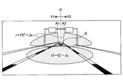
- FIG. 3 is a diagram showing an example of a restriction mode of the irradiation range of the high beam headlamp of the headlamp 50.
- FIG. 3 is shown by a front environment image.
- the high beam headlamp is controlled so that the object is not irradiated by the high beam headlamp.
- the irradiation area is limited.
- the irradiation area of the high beam headlamp is limited in such a manner that it extends from the horizontal center line O in the left and right directions (Y1 and Y2 directions).
- the irradiation area of the high beam headlamp is the line A1 (the line on the left side of the left end of the other vehicle estimation object) according to the horizontal position of the other vehicle estimation object X.
- the irradiation area of the right high beam headlamp is limited to line A2 (a line on the right side of the right end of the other vehicle estimated object).
- the horizontal position of the other vehicle estimated object X may be calculated by the image recognition unit 42.
- the relationship between the horizontal position (calculated value) of the other vehicle estimated object X and the position of the lamp shade, that is, the limit position of the irradiation area of the high beam headlamp (lines A1 and A2 in the illustrated example) is designed in advance. , May be stored in a map format.
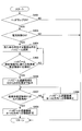
- FIG. 4 is a flowchart showing an example of main processing executed by the control ECU 40 of this embodiment. The process shown in FIG. 4 may be started when the ignition switch of the vehicle is turned on.
- step 402 based on the state of the switch 20, it is determined whether or not the headlamp 50 is on. If the headlamp 50 is on, the process proceeds to step 403, and if the headlamp 50 is off, the process ends.
- step 403 based on the state of the switch 20, it is determined whether or not the light distribution control of the headlamp 50 is on. If the light distribution control of the headlamp 50 is on, the process proceeds to step 404, and if the light distribution control of the headlamp 50 is off, the process ends.
- the image recognition part 42 image-processes the front environment image provided in real time from the image sensor 10, and the other vehicle (preceding vehicle or opposite vehicle) which may exist ahead of a vehicle is processed. It is always determined (tracked) whether a vehicle is present. Here, it is assumed that the preceding vehicle is detected as the other vehicle estimated object.
- the lamp shade controller 46 limits the irradiation area of the high beam headlamp so that the preceding vehicle is not irradiated by the high beam headlamp. That is, the lamp shade control unit 46 limits the irradiation area of the high beam headlamp so that the high beam headlamp irradiates the area other than the area where the preceding vehicle exists.
- the irradiation area of the high beam headlamp is limited to the line A1 according to the horizontal position of the other vehicle estimated object X, and the right high beam The irradiation area of the headlamp is limited to line A2.
- the positions of the lines A1 and A2 may be dynamically changed according to changes in the position of the other vehicle estimated object X (a preceding vehicle in the example shown in FIG. 3) that is updated as needed.
- Step 405 it is determined whether or not a new other vehicle estimated object is detected in the image recognition unit 42 within the current irradiation region of the high beam headlamp. If a new vehicle estimate is detected within the irradiation area of the high beam headlamp, the process proceeds to step 406. Otherwise, the process returns to step 404.
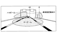
- the lamp shade control unit 46 limits the irradiation area of the high beam headlamp so that the new other vehicle estimated object is not irradiated by the high beam headlamp. For example, as shown in FIG. 5A, when a reflecting object (reflecting object such as a sign) on the road enters the irradiation region of the high beam headlamp, reflected light from the reflecting object is captured in the front environment image. In this case, the image recognition unit 42 may detect an object that emits the reflected light (a reflective object such as a sign) as a new other vehicle estimated object X1. In such a case, as shown in FIG.
- the lamp shade control unit 46 limits the irradiation area of the high beam headlamp so that the new other vehicle estimated object X1 is not irradiated by the high beam headlamp.
- the irradiation area of the high beam headlamp is the line B (the line on the right side of the right end of the other vehicle thrust object X) according to the horizontal position of the other vehicle thrust object X. ). That is, the irradiation blocking region of the right high beam headlamp is expanded from the region between the line O and the line A2 (see FIG. 5A) to the region between the line O and the line B (see FIG. 5B). 5A and 5B are shown by the front environment image.
- the image recognition unit 42 determines whether the image related to the new other vehicle estimated object detected in step 405 has moved outside the detectable area (camera angle of view) of the image sensor 10.
- the image related to the new estimated other vehicle object detected in step 405 may be tracked and specified in the front environment image obtained continuously in time series, or for each front environment image. May be specified independently.
- the new other vehicle estimated object detected in step 405 is displayed in the front environment image. Such an image is not captured by the image sensor 10.
- the process proceeds to step 409, and while the image related to the new other vehicle estimated object detected in step 405 is captured by the image sensor 10, the process of step 407 is performed via step 408. repeat.
- an object other than the other vehicle such as a reflecting object (a reflecting object such as a sign) on the road is detected as the other vehicle estimated object, and as a result, as shown in FIG. If the irradiation area of the high beam headlamp is limited so that the other vehicle estimated object X1 is not irradiated by the high beam headlamp, the object detected as the new other vehicle estimated object X1 is not irradiated by the high beam headlamp.
- the new other vehicle estimated object X1 since the light (reflected light) from the object detected as the new other vehicle estimated object X1 is substantially eliminated (or weakened), in the subsequent forward environment image, the new other vehicle estimated object X1 The object detected as is no longer detected by the image recognition unit 42 as the other vehicle estimated object. Accordingly, since the object detected as the new other vehicle estimated object X1 is not detected as the other vehicle estimated object under normal circumstances, the irradiation blocking area of the high beam headlamp enlarged in step 406 is reduced to the original state. It will be. However, when the high-beam headlamp irradiation blockage area is restored to the original state, the same reflector is again detected by the image recognition unit 42 as the other vehicle estimated object.
- the irradiation area of the high beam headlamp is limited again so that the reflector is not irradiated by the high beam headlamp.
- the expansion and reduction of the irradiation area of the high beam headlamp are repeated, there is a risk of unpleasant dazzling to drivers of other vehicles such as preceding cars and oncoming cars, or misunderstood as passing, Moreover, it is not desirable from the viewpoint of merchantability.
- the irradiation area of the high beam headlamp is repeatedly expanded and decreased due to a reflection on the road (a reflection object such as a sign) detected by the image recognition unit 42 as the other vehicle estimation object. Built-in logic to prevent this.
- step 408 it is prohibited to reduce the irradiation blocking area of the high beam headlamp enlarged in step 406 to the original state. That is, the movement of the irradiation blocking boundary line from the line B toward the line A2 is prohibited in the irradiation blocking area of the right high beam headlamp.
- the irradiation cutoff boundary line is maintained at the line B, but the position of the line B is an object detected as the other vehicle estimated object X1 that is updated as needed (in the example shown in FIG. 5A, a reflector on the road).
- the position may be dynamically changed according to the change in the position or the like. For example, when the reflecting object on the road is a fixed object as in the example shown in FIG.
- the image of the reflecting object moves to the right as the vehicle travels in the front environment image.
- the line B may also be moved in the right direction according to the movement of the reflecting object in the front environment image.
- the movement of line B may be performed in a feedback manner.
- the irradiation area line B of the high beam headlamp corresponds to each time when the reflecting object is irradiated again by the high beam headlamp as the vehicle travels (every time the image recognition unit 42 detects again as another vehicle estimation object). It may be moved.
- the line B is fixed until the reflector is irradiated again by the high beam headlamp as the vehicle travels, and every time the reflector is irradiated again by the high beam headlamp as the vehicle travels, the line B is fixed. B moves outward.
- the movement of the line B may be executed in a feed forward manner. For example, when the position of the object detected as the other vehicle estimated object X1 by a stereo camera or the like (in the example shown in FIG.
- the absolute position or the relative position of the reflecting object on the road can be calculated, the other vehicle estimated object
- the position of the line B (a position where the object detected as the other vehicle estimated object X1 is not irradiated by the high beam headlamp) may be determined according to the position of the object detected as X1. Further, the position of the line B (detected as the other vehicle estimated object X1) based on the change in the vehicle traveling direction (detected from the steering angle sensor) and the change in the vehicle speed and position (detected from the vehicle speed sensor and GPS receiver). The position where the object is not illuminated by the high beam headlamp may be updated.
- step 409 it is permitted to reduce the irradiation blocking area of the high beam headlamp enlarged in step 406 to the original state. That is, movement of the irradiation blocking boundary line from the line B toward the line A2 is permitted for the irradiation blocking region of the right high beam headlamp. As a result, the irradiation blocking area of the high beam headlamp enlarged in step 406 is returned to the original state (for example, the state shown in FIG. 5A).
- the irradiation area of the high beam headlamp is limited so that the other vehicle estimated object is not irradiated by the high beam headlamp, but after the limitation, the object detected as the other vehicle estimated object is not detected as the other vehicle estimated object. Even in this case, the limitation on the irradiation area of the high beam headlamp is maintained until the image related to the object detected as the other vehicle estimated object comes out of the camera angle of view. Repeating can be effectively prevented.
- FIG. 6 is a flowchart showing another example of the main process executed by the control ECU 40 of this embodiment. The process shown in FIG. 6 may be started when the ignition switch of the vehicle is turned on.
- Steps other than step 507 in FIG. 6 may be substantially the same as the corresponding steps in FIG. For this reason, the process of step 507 is demonstrated here.
- step 507 it is determined whether or not a predetermined delay time has elapsed since the time of enlargement processing of the irradiation blocking area of the high beam headlamp executed in step 506.
- the predetermined delay time is sufficiently longer than the image recognition processing cycle by the image recognition unit 42.
- the predetermined delay time ideally corresponds to the time until the image related to the new other vehicle estimated object detected in step 505 disappears outside the camera angle of view, and may be a predetermined fixed time. Alternatively, the predetermined delay time may be a variable time. In this case, a typical road reflection object (a reflection object such as a sign) is detected on the road when the image recognition unit 42 detects the other vehicle estimation object.
- the predetermined delay time may be equivalent to a time obtained by dividing the distance by the vehicle speed (current vehicle speed or average vehicle speed or the like).
- the vehicle speed current vehicle speed or average vehicle speed or the like.
- the predetermined delay time may be set according to the position of the object detected as X1 (distance from the host vehicle).
- the predetermined delay time may be equivalent to a time obtained by dividing the distance between the object detected as the other vehicle estimated object X1 and the host vehicle by the vehicle speed (current vehicle speed, average vehicle speed, or the like).
- the irradiation area of the high beam headlamp is limited so that the other vehicle estimated object is not irradiated by the high beam headlamp, but the limitation is maintained for a predetermined delay time, so that the irradiation area of the high beam headlamp is expanded and decreased. Can be effectively suppressed.
- FIG. 7 is a flowchart showing another example of the main process executed by the control ECU 40 of this embodiment. The process shown in FIG. 7 may be started when the ignition switch of the vehicle is turned on.
- Steps 602-606 in FIG. 7 may be substantially the same as the corresponding steps 402-406 in FIG. For this reason, the processing peculiar to FIG. 7 will be described here.
- step 607 the image recognition unit 42 determines again whether the new other vehicle estimated object detected in step 605 is another vehicle or a reflector other than the other vehicle (irradiation of the high beam headlamp). It is determined again after the area is expanded to line B).
- the new other vehicle estimated object detected in step 605 is actually another vehicle, it is detected as the other vehicle estimated object because the other vehicle itself emits light. Even if the irradiation area of the high beam headlamp is limited so that the object is not irradiated by the high beam headlamp, the image recognition unit 42 continues to detect the other vehicle estimated object.
- step 605 if the new other vehicle estimated object detected in step 605 is not actually another vehicle (that is, if it is a reflector other than the other vehicle), the other vehicle estimated is not emitted.
- the image recognition unit 42 does not detect the other vehicle estimated object. Therefore, using this difference, it may be determined whether the new other vehicle estimated object detected in step 605 is another vehicle or a reflector other than the other vehicle. If the new other vehicle estimated object detected in step 605 is another vehicle, the process returns to step 604. In step 604, the lamp shade control unit 46 determines that the preceding vehicle and the new other vehicle estimated object are high beam headlamps.
- step 605 The irradiation area of the high beam headlamp is limited so as not to be irradiated.
- the process proceeds to step 609.
- step 609 it is permitted to reduce the irradiation blocking area of the high beam headlamp enlarged in step 606 to the original state. That is, movement of the irradiation blocking boundary line from the line B toward the line A2 is permitted for the irradiation blocking region of the right high beam headlamp.
- the non-other vehicle determined in step 607 is not treated as an other vehicle estimated object. That is, under normal circumstances, when the irradiation blocking area of the high beam headlamp is reduced to the original state in step 609, the non-other vehicle determined in step 607 is again irradiated with the high beam headlamp, and the image recognition unit 42 In this case, it is detected again as the other vehicle estimated object.
- the image related to the non-other vehicle is displayed while the image related to the non-other vehicle is being tracked in the forward environment image. Even when the detection condition of the other vehicle estimated object is satisfied, it is not detected as the other vehicle estimated object.
- the above-described embodiment relates to the irradiation region of the high beam headlamp, but it can be similarly applied to the irradiation region of the low beam headlamp.
- a low beam headlamp it is possible to effectively prevent the irradiation area from being repeatedly enlarged and reduced due to a reflector attached to or placed on the road surface.
- the other vehicle estimated object is detected using only the front environment image obtained from the image sensor 10, but other information is additionally used to detect the other vehicle estimated object. It is also possible. For example, other vehicle information (existence, position, speed, etc. of other vehicles) from various radar devices such as millimeter wave radar, laser radar, etc., other vehicle information (existence, position, speed of other vehicles) obtained by inter-vehicle communication It is also possible to detect the other vehicle estimated object using the above.
- the irradiation area of the high beam headlamp is limited in such a manner as to extend from the horizontal center line O to the left and right directions (Y1 and Y2 directions) as shown in FIG. 3), the mode of limiting the irradiation area of the high beam headlamp may be arbitrary.
- the restriction mode of the irradiation region of the high beam headlamp as shown in FIG. 5B, as shown in FIG. 8, the outside (right side) from the line B3 (the line on the left side of the left end of the other vehicle estimated object) You may restrict
- FIG. 8 is shown by a front environment image.
- the irradiation area of the high beam headlamp is varied in the horizontal direction, but may be varied in the vertical direction (up and down direction) instead of or in addition thereto.
- the up and down direction it is possible to effectively prevent repeated enlargement and reduction of the irradiation area due to a reflector such as a road sign installed just above the roadway.
Abstract
L'invention concerne un dispositif de commande de la distribution de lumière pour véhicule configuré pour comprendre : un appareil photo qui photographie la zone à l'avant d'un véhicule ; un dispositif d'éclairage qui éclaire la zone à l'avant du véhicule ; et un dispositif de commande, qui détecte comme étant un objet estimé être un autre véhicule une image répondant à une condition prescrite à l'intérieur d'une image obtenue à l'aide de l'appareil photographique et qui commande la distribution de la lumière d'éclairage en se basant sur le résultat de la détection. Lorsqu'un objet estimé être un autre véhicule est détecté dans la région d'éclairage, le dispositif de commande limite la région d'éclairage de sorte que l'éclairage ne soit pas projeté sur l'objet estimé être un autre véhicule ; et lorsqu'un objet estimé être un autre véhicule n'est pas détecté dans la région d'éclairage dans laquelle l'éclairage est restreint, le dispositif de commande inhibe le désactivation de la restriction de la région d'éclairage jusqu'à ce qu'une condition de désactivation prescrite soit satisfaite.
Priority Applications (5)
| Application Number | Priority Date | Filing Date | Title |
|---|---|---|---|
| JP2012527526A JP5413511B2 (ja) | 2010-08-06 | 2010-08-06 | 車両配光制御装置及び方法 |
| PCT/JP2010/063423 WO2012017559A1 (fr) | 2010-08-06 | 2010-08-06 | Dispositif et procédé de commande de la distribution de lumière pour véhicule |
| US13/696,731 US8827514B2 (en) | 2010-08-06 | 2010-08-06 | Vehicle light distribution control apparatus and method |
| CN201080068121.XA CN103249597B (zh) | 2010-08-06 | 2010-08-06 | 车辆配光控制装置以及方法 |
| EP10855648.1A EP2602154B1 (fr) | 2010-08-06 | 2010-08-06 | Dispositif et procédé de commande de la distribution de lumière pour véhicule |
Applications Claiming Priority (1)
| Application Number | Priority Date | Filing Date | Title |
|---|---|---|---|
| PCT/JP2010/063423 WO2012017559A1 (fr) | 2010-08-06 | 2010-08-06 | Dispositif et procédé de commande de la distribution de lumière pour véhicule |
Publications (1)
| Publication Number | Publication Date |
|---|---|
| WO2012017559A1 true WO2012017559A1 (fr) | 2012-02-09 |
Family
ID=45559089
Family Applications (1)
| Application Number | Title | Priority Date | Filing Date |
|---|---|---|---|
| PCT/JP2010/063423 WO2012017559A1 (fr) | 2010-08-06 | 2010-08-06 | Dispositif et procédé de commande de la distribution de lumière pour véhicule |
Country Status (5)
| Country | Link |
|---|---|
| US (1) | US8827514B2 (fr) |
| EP (1) | EP2602154B1 (fr) |
| JP (1) | JP5413511B2 (fr) |
| CN (1) | CN103249597B (fr) |
| WO (1) | WO2012017559A1 (fr) |
Cited By (5)
| Publication number | Priority date | Publication date | Assignee | Title |
|---|---|---|---|---|
| WO2013172398A1 (fr) * | 2012-05-16 | 2013-11-21 | 株式会社デンソー | Dispositif permettant de détecter un feu de véhicule et procédé afférent |
| CN104220299A (zh) * | 2012-03-28 | 2014-12-17 | 株式会社电装 | 灯光控制设备和灯光控制程序 |
| JP2019172105A (ja) * | 2018-03-28 | 2019-10-10 | ダイハツ工業株式会社 | 配光制御装置 |
| CN111791796A (zh) * | 2019-04-08 | 2020-10-20 | 丰田自动车株式会社 | 车辆的前照灯控制装置 |
| WO2021002297A1 (fr) * | 2019-07-03 | 2021-01-07 | 株式会社小糸製作所 | Système d'éclairage de véhicule, système de véhicule et véhicule |
Families Citing this family (22)
| Publication number | Priority date | Publication date | Assignee | Title |
|---|---|---|---|---|
| WO2012137332A1 (fr) | 2011-04-07 | 2012-10-11 | パイオニア株式会社 | Système de détection des conditions autour d'un corps mobile |
| DE102011055606A1 (de) * | 2011-11-22 | 2013-05-23 | Hella Kgaa Hueck & Co. | Verfahren und Steuergerät zum Steuern von Hauptscheinwerfern mit einstellbarer vertikaler Hell-Dunkel-Grenze zum Entblenden von Objekten |
| KR101360344B1 (ko) * | 2012-02-17 | 2014-02-10 | 현대모비스 주식회사 | 차량용 램프 제어장치 및 제어방법 |
| US9550448B2 (en) * | 2013-07-11 | 2017-01-24 | Koito Manufacturing Co., Ltd. | Light distribution control method and light distribution control device for a vehicular headlamp |
| JP6264909B2 (ja) * | 2014-01-31 | 2018-01-24 | 株式会社デンソー | 前照灯制御装置及び前照灯 |
| JP6599613B2 (ja) | 2014-12-25 | 2019-10-30 | 株式会社小糸製作所 | 配光可変車両用灯具 |
| AT517415B1 (de) * | 2015-06-29 | 2017-04-15 | Zkw Group Gmbh | Steuerungsvorrichtung für eine Beleuchtungsvorrichtung eines Kraftfahrzeuges sowie Verfahren zum Steuern einer solchen Beleuchtungsvorrichtung |
| JP6558228B2 (ja) * | 2015-11-30 | 2019-08-14 | 株式会社Jvcケンウッド | ヘッドライト装置、ヘッドライト制御方法およびヘッドライト制御プログラム |
| US10745009B2 (en) * | 2016-12-21 | 2020-08-18 | Samsung Electronics Co., Ltd. | Electronic apparatus for determining a dangerous situation of a vehicle and method of operating the same |
| DE102017200574B4 (de) * | 2017-01-16 | 2019-12-12 | Robert Bosch Gmbh | Verfahren zum Überwachen eines Umfelds eines Fahrzeugs |
| KR101908423B1 (ko) * | 2017-04-10 | 2018-10-16 | 엘지전자 주식회사 | 차량에 구비된 차량 제어 장치 및 그것의 차량 제어 방법 |
| US11525688B2 (en) | 2017-12-15 | 2022-12-13 | Samsung Electronics Co., Ltd. | Method and apparatus for determining object position |
| KR102521656B1 (ko) | 2018-01-03 | 2023-04-13 | 삼성전자주식회사 | 객체를 인식하는 방법 및 장치 |
| KR102541561B1 (ko) | 2018-02-12 | 2023-06-08 | 삼성전자주식회사 | 차량의 주행을 위한 정보를 제공하는 방법 및 그 장치들 |
| JP7046734B2 (ja) * | 2018-06-27 | 2022-04-04 | 矢崎総業株式会社 | 車内照明システム |
| DE102019211732A1 (de) * | 2018-08-06 | 2020-02-06 | Koito Manufacturing Co., Ltd. | Fahrzeugleuchte |
| JP7252755B2 (ja) * | 2018-12-27 | 2023-04-05 | 株式会社小糸製作所 | アクティブセンサ、物体識別システム、車両、車両用灯具 |
| US11300974B2 (en) * | 2019-07-18 | 2022-04-12 | GM Global Technology Operations LLC | Perception methods and systems for low lighting conditions |
| JP7152703B2 (ja) * | 2019-09-03 | 2022-10-13 | トヨタ自動車株式会社 | 車両用照明装置 |
| CN114312550A (zh) * | 2021-12-28 | 2022-04-12 | 北京梧桐车联科技有限责任公司 | 车辆前照灯的控制方法、装置、设备及存储介质 |
| US20230309207A1 (en) * | 2022-03-25 | 2023-09-28 | Microsoft Technology Licensing, Llc | Illumination light control based on orientation |
| US11590880B1 (en) * | 2022-05-13 | 2023-02-28 | Rivian Ip Holdings, Llc | Predictive illumination shaping |
Citations (4)
| Publication number | Priority date | Publication date | Assignee | Title |
|---|---|---|---|---|
| JPH0210141U (fr) * | 1988-07-04 | 1990-01-23 | ||
| WO2008037388A2 (fr) | 2006-09-27 | 2008-04-03 | Volkswagen Aktiengesellschaft | Ensemble phare pour un véhicule et procédé de commande associé |
| JP2009211963A (ja) | 2008-03-05 | 2009-09-17 | Koito Mfg Co Ltd | 車両用ランプ |
| JP2010162960A (ja) * | 2009-01-13 | 2010-07-29 | Koito Mfg Co Ltd | 車両用前照灯装置 |
Family Cites Families (12)
| Publication number | Priority date | Publication date | Assignee | Title |
|---|---|---|---|---|
| JPS62253545A (ja) | 1986-04-25 | 1987-11-05 | Mazda Motor Corp | 車両の自動ライトコントロ−ル装置 |
| US6587573B1 (en) * | 2000-03-20 | 2003-07-01 | Gentex Corporation | System for controlling exterior vehicle lights |
| JP4466604B2 (ja) | 2006-04-26 | 2010-05-26 | 株式会社デンソー | 車両用前照灯装置 |
| JP4484856B2 (ja) * | 2006-10-06 | 2010-06-16 | 日立オートモティブシステムズ株式会社 | 自動車用ヘッドライト制御装置 |
| JP4349414B2 (ja) * | 2006-12-15 | 2009-10-21 | トヨタ自動車株式会社 | 車両用照明装置 |
| FR2911206B1 (fr) * | 2006-12-21 | 2009-05-08 | Valeo Vision Sa | Procede de discrimination automatique de zones lumineuses detectees par un dispositif d'aide a la conduite pour vehicule. |
| JP4538468B2 (ja) * | 2007-02-27 | 2010-09-08 | 日立オートモティブシステムズ株式会社 | 画像処理装置,画像処理方法、及び画像処理システム |
| JP4970145B2 (ja) * | 2007-05-30 | 2012-07-04 | 株式会社小糸製作所 | 車両用前照灯 |
| JP2009179113A (ja) * | 2008-01-29 | 2009-08-13 | Koito Mfg Co Ltd | 車両用前照灯装置およびその制御方法 |
| JP2009214812A (ja) * | 2008-03-12 | 2009-09-24 | Koito Mfg Co Ltd | 車両用前照灯装置およびその制御方法 |
| JP2009220649A (ja) * | 2008-03-14 | 2009-10-01 | Koito Mfg Co Ltd | 車両用前照灯装置 |
| DE102008059630A1 (de) * | 2008-11-28 | 2010-06-02 | Adc Automotive Distance Control Systems Gmbh | Verfahren zur Erkennung von Fahrzeuglichtern und Retroreflektoren mit einem Kamerasystem |
-
2010
- 2010-08-06 JP JP2012527526A patent/JP5413511B2/ja active Active
- 2010-08-06 EP EP10855648.1A patent/EP2602154B1/fr active Active
- 2010-08-06 WO PCT/JP2010/063423 patent/WO2012017559A1/fr active Application Filing
- 2010-08-06 CN CN201080068121.XA patent/CN103249597B/zh active Active
- 2010-08-06 US US13/696,731 patent/US8827514B2/en active Active
Patent Citations (4)
| Publication number | Priority date | Publication date | Assignee | Title |
|---|---|---|---|---|
| JPH0210141U (fr) * | 1988-07-04 | 1990-01-23 | ||
| WO2008037388A2 (fr) | 2006-09-27 | 2008-04-03 | Volkswagen Aktiengesellschaft | Ensemble phare pour un véhicule et procédé de commande associé |
| JP2009211963A (ja) | 2008-03-05 | 2009-09-17 | Koito Mfg Co Ltd | 車両用ランプ |
| JP2010162960A (ja) * | 2009-01-13 | 2010-07-29 | Koito Mfg Co Ltd | 車両用前照灯装置 |
Non-Patent Citations (2)
| Title |
|---|
| BERND DREIER; ERNST-OLAF ROSENHAHN: "Camera Controlled Adaptive Cut-off and Adaptive Partial High Beam Applications", 8TH INTERNATIONAL SYMPOSIUM ON AUTOMOTIVE LIGHTING 2009 VERSION 13, 2009 |
| See also references of EP2602154A4 |
Cited By (11)
| Publication number | Priority date | Publication date | Assignee | Title |
|---|---|---|---|---|
| CN104220299A (zh) * | 2012-03-28 | 2014-12-17 | 株式会社电装 | 灯光控制设备和灯光控制程序 |
| US10279729B2 (en) | 2012-03-28 | 2019-05-07 | Denso Corporation | Light control device and light control program |
| WO2013172398A1 (fr) * | 2012-05-16 | 2013-11-21 | 株式会社デンソー | Dispositif permettant de détecter un feu de véhicule et procédé afférent |
| JP2013237389A (ja) * | 2012-05-16 | 2013-11-28 | Denso Corp | 灯火検出装置及び車両制御システム |
| JP2019172105A (ja) * | 2018-03-28 | 2019-10-10 | ダイハツ工業株式会社 | 配光制御装置 |
| JP7055563B2 (ja) | 2018-03-28 | 2022-04-18 | ダイハツ工業株式会社 | 配光制御装置 |
| CN111791796A (zh) * | 2019-04-08 | 2020-10-20 | 丰田自动车株式会社 | 车辆的前照灯控制装置 |
| JP2020172123A (ja) * | 2019-04-08 | 2020-10-22 | トヨタ自動車株式会社 | 車両の前照灯制御装置 |
| JP7207113B2 (ja) | 2019-04-08 | 2023-01-18 | トヨタ自動車株式会社 | 車両の前照灯制御装置 |
| WO2021002297A1 (fr) * | 2019-07-03 | 2021-01-07 | 株式会社小糸製作所 | Système d'éclairage de véhicule, système de véhicule et véhicule |
| JP7340607B2 (ja) | 2019-07-03 | 2023-09-07 | 株式会社小糸製作所 | 車両用照明システム、車両システム及び車両 |
Also Published As
| Publication number | Publication date |
|---|---|
| US8827514B2 (en) | 2014-09-09 |
| EP2602154B1 (fr) | 2016-03-30 |
| JP5413511B2 (ja) | 2014-02-12 |
| CN103249597B (zh) | 2015-04-29 |
| JPWO2012017559A1 (ja) | 2013-09-19 |
| EP2602154A8 (fr) | 2013-08-28 |
| CN103249597A (zh) | 2013-08-14 |
| US20130155704A1 (en) | 2013-06-20 |
| EP2602154A4 (fr) | 2014-04-30 |
| EP2602154A1 (fr) | 2013-06-12 |
Similar Documents
| Publication | Publication Date | Title |
|---|---|---|
| JP5413511B2 (ja) | 車両配光制御装置及び方法 | |
| JP6453669B2 (ja) | 車両用前照灯制御装置 | |
| JP4458141B2 (ja) | ライト制御装置 | |
| JP5293893B2 (ja) | 車両用照明装置及び車両用ヘッドランプの制御方法 | |
| JP6350402B2 (ja) | 車両用前照灯制御装置 | |
| WO2012063365A1 (fr) | Système de commande de distribution de lumière pour véhicule et procédé de commande de distribution de lumière pour véhicule | |
| US9199573B2 (en) | Vehicle light distribution control device and vehicle light distribution control method | |
| JP5372616B2 (ja) | 車両用前照灯の配光制御システム | |
| EP2731825B1 (fr) | Dispositif de commande de distribution de lumière de véhicule et procédé de commande de distribution de lumière de véhicule | |
| CN110914109A (zh) | 照射系统和照射方法 | |
| US9545875B2 (en) | Method for controlling a light emission of a headlight of a vehicle | |
| WO2018110389A1 (fr) | Système d'éclairage de véhicule et véhicule | |
| JP4609274B2 (ja) | 車両のヘッドライト制御装置 | |
| JP2011037343A (ja) | 車両用前照灯の配光制御システム | |
| JP5195390B2 (ja) | 前方照射自動制御装置 | |
| JP2012196999A (ja) | 車両用照明装置及び方法 | |
| CN110859018B (zh) | 车辆用灯具 | |
| JP5636483B2 (ja) | 車両用前照灯の配光制御システム | |
| JP2012185669A (ja) | 車両検知装置及びこれを用いる車両配光制御装置 | |
| JP6663770B2 (ja) | 車両の配光制御装置 | |
| JP2019108101A (ja) | 車両の制御装置 | |
| JP5392226B2 (ja) | 前照灯制御装置 |
Legal Events
| Date | Code | Title | Description |
|---|---|---|---|
| 121 | Ep: the epo has been informed by wipo that ep was designated in this application |
Ref document number: 10855648 Country of ref document: EP Kind code of ref document: A1 |
|
| WWE | Wipo information: entry into national phase |
Ref document number: 2012527526 Country of ref document: JP |
|
| WWE | Wipo information: entry into national phase |
Ref document number: 2010855648 Country of ref document: EP |
|
| WWE | Wipo information: entry into national phase |
Ref document number: 13696731 Country of ref document: US |
|
| NENP | Non-entry into the national phase |
Ref country code: DE |