WO2012017559A1 - Vehicle light distribution control device and method - Google Patents
Vehicle light distribution control device and method Download PDFInfo
- Publication number
- WO2012017559A1 WO2012017559A1 PCT/JP2010/063423 JP2010063423W WO2012017559A1 WO 2012017559 A1 WO2012017559 A1 WO 2012017559A1 JP 2010063423 W JP2010063423 W JP 2010063423W WO 2012017559 A1 WO2012017559 A1 WO 2012017559A1
- Authority
- WO
- WIPO (PCT)
- Prior art keywords
- vehicle
- illumination light
- control device
- detected
- image
- Prior art date
Links
Images


Classifications
-
- B—PERFORMING OPERATIONS; TRANSPORTING
- B60—VEHICLES IN GENERAL
- B60Q—ARRANGEMENT OF SIGNALLING OR LIGHTING DEVICES, THE MOUNTING OR SUPPORTING THEREOF OR CIRCUITS THEREFOR, FOR VEHICLES IN GENERAL
- B60Q1/00—Arrangement of optical signalling or lighting devices, the mounting or supporting thereof or circuits therefor
- B60Q1/02—Arrangement of optical signalling or lighting devices, the mounting or supporting thereof or circuits therefor the devices being primarily intended to illuminate the way ahead or to illuminate other areas of way or environments
- B60Q1/04—Arrangement of optical signalling or lighting devices, the mounting or supporting thereof or circuits therefor the devices being primarily intended to illuminate the way ahead or to illuminate other areas of way or environments the devices being headlights
- B60Q1/06—Arrangement of optical signalling or lighting devices, the mounting or supporting thereof or circuits therefor the devices being primarily intended to illuminate the way ahead or to illuminate other areas of way or environments the devices being headlights adjustable, e.g. remotely-controlled from inside vehicle
- B60Q1/08—Arrangement of optical signalling or lighting devices, the mounting or supporting thereof or circuits therefor the devices being primarily intended to illuminate the way ahead or to illuminate other areas of way or environments the devices being headlights adjustable, e.g. remotely-controlled from inside vehicle automatically
-
- B—PERFORMING OPERATIONS; TRANSPORTING
- B60—VEHICLES IN GENERAL
- B60Q—ARRANGEMENT OF SIGNALLING OR LIGHTING DEVICES, THE MOUNTING OR SUPPORTING THEREOF OR CIRCUITS THEREFOR, FOR VEHICLES IN GENERAL
- B60Q1/00—Arrangement of optical signalling or lighting devices, the mounting or supporting thereof or circuits therefor
- B60Q1/02—Arrangement of optical signalling or lighting devices, the mounting or supporting thereof or circuits therefor the devices being primarily intended to illuminate the way ahead or to illuminate other areas of way or environments
- B60Q1/04—Arrangement of optical signalling or lighting devices, the mounting or supporting thereof or circuits therefor the devices being primarily intended to illuminate the way ahead or to illuminate other areas of way or environments the devices being headlights
- B60Q1/14—Arrangement of optical signalling or lighting devices, the mounting or supporting thereof or circuits therefor the devices being primarily intended to illuminate the way ahead or to illuminate other areas of way or environments the devices being headlights having dimming means
- B60Q1/1415—Dimming circuits
- B60Q1/1423—Automatic dimming circuits, i.e. switching between high beam and low beam due to change of ambient light or light level in road traffic
- B60Q1/143—Automatic dimming circuits, i.e. switching between high beam and low beam due to change of ambient light or light level in road traffic combined with another condition, e.g. using vehicle recognition from camera images or activation of wipers
-
- G—PHYSICS
- G06—COMPUTING; CALCULATING OR COUNTING
- G06V—IMAGE OR VIDEO RECOGNITION OR UNDERSTANDING
- G06V20/00—Scenes; Scene-specific elements
- G06V20/50—Context or environment of the image
- G06V20/56—Context or environment of the image exterior to a vehicle by using sensors mounted on the vehicle
- G06V20/58—Recognition of moving objects or obstacles, e.g. vehicles or pedestrians; Recognition of traffic objects, e.g. traffic signs, traffic lights or roads
- G06V20/584—Recognition of moving objects or obstacles, e.g. vehicles or pedestrians; Recognition of traffic objects, e.g. traffic signs, traffic lights or roads of vehicle lights or traffic lights
-
- B—PERFORMING OPERATIONS; TRANSPORTING
- B60—VEHICLES IN GENERAL
- B60Q—ARRANGEMENT OF SIGNALLING OR LIGHTING DEVICES, THE MOUNTING OR SUPPORTING THEREOF OR CIRCUITS THEREFOR, FOR VEHICLES IN GENERAL
- B60Q2300/00—Indexing codes for automatically adjustable headlamps or automatically dimmable headlamps
- B60Q2300/05—Special features for controlling or switching of the light beam
- B60Q2300/052—Switching delay, i.e. the beam is not switched or changed instantaneously upon occurrence of a condition change
-
- B—PERFORMING OPERATIONS; TRANSPORTING
- B60—VEHICLES IN GENERAL
- B60Q—ARRANGEMENT OF SIGNALLING OR LIGHTING DEVICES, THE MOUNTING OR SUPPORTING THEREOF OR CIRCUITS THEREFOR, FOR VEHICLES IN GENERAL
- B60Q2300/00—Indexing codes for automatically adjustable headlamps or automatically dimmable headlamps
- B60Q2300/05—Special features for controlling or switching of the light beam
- B60Q2300/056—Special anti-blinding beams, e.g. a standard beam is chopped or moved in order not to blind
-
- B—PERFORMING OPERATIONS; TRANSPORTING
- B60—VEHICLES IN GENERAL
- B60Q—ARRANGEMENT OF SIGNALLING OR LIGHTING DEVICES, THE MOUNTING OR SUPPORTING THEREOF OR CIRCUITS THEREFOR, FOR VEHICLES IN GENERAL
- B60Q2300/00—Indexing codes for automatically adjustable headlamps or automatically dimmable headlamps
- B60Q2300/40—Indexing codes relating to other road users or special conditions
- B60Q2300/41—Indexing codes relating to other road users or special conditions preceding vehicle
-
- B—PERFORMING OPERATIONS; TRANSPORTING
- B60—VEHICLES IN GENERAL
- B60Q—ARRANGEMENT OF SIGNALLING OR LIGHTING DEVICES, THE MOUNTING OR SUPPORTING THEREOF OR CIRCUITS THEREFOR, FOR VEHICLES IN GENERAL
- B60Q2300/00—Indexing codes for automatically adjustable headlamps or automatically dimmable headlamps
- B60Q2300/40—Indexing codes relating to other road users or special conditions
- B60Q2300/42—Indexing codes relating to other road users or special conditions oncoming vehicle
-
- B—PERFORMING OPERATIONS; TRANSPORTING
- B60—VEHICLES IN GENERAL
- B60Q—ARRANGEMENT OF SIGNALLING OR LIGHTING DEVICES, THE MOUNTING OR SUPPORTING THEREOF OR CIRCUITS THEREFOR, FOR VEHICLES IN GENERAL
- B60Q2300/00—Indexing codes for automatically adjustable headlamps or automatically dimmable headlamps
- B60Q2300/40—Indexing codes relating to other road users or special conditions
- B60Q2300/45—Special conditions, e.g. pedestrians, road signs or potential dangers
Landscapes
- Engineering & Computer Science (AREA)
- Mechanical Engineering (AREA)
- Physics & Mathematics (AREA)
- General Physics & Mathematics (AREA)
- Multimedia (AREA)
- Theoretical Computer Science (AREA)
- Lighting Device Outwards From Vehicle And Optical Signal (AREA)
Abstract
A vehicle light distribution control device is configured to comprise: a camera that photographs the area ahead of a vehicle; an illumination device that projects illumination ahead of the vehicle; and a control device that detects, as an object that is estimated to be another vehicle, an image that satisfies a prescribed condition within an image that is obtained with the camera, and controls light distribution of the illumination on the basis of the detection result. When an object estimated to be another vehicle is detected within the region of projection of illumination, the control device restricts the region of projection of illumination such that the illumination is not projected upon the object estimated to be another vehicle; and when an object estimated to be another vehicle is not detected in the region of projection of illumination wherein the projection of illumination is restricted, the control device inhibits the disengagement of the restriction of the region of projection of illumination until a prescribed disengagement condition is met.
Description
本発明は、車両配光制御装置及び方法に関する。
The present invention relates to a vehicle light distribution control device and method.
従来から、先行車や対向車のような他車両に対してグレアを与えないように、カメラによる他車両の検出結果に基づいて、車両前方を照明するための照明光の配光を制御する技術が知られている(例えば、特許文献1、2、非特許文献3参照)。
Conventionally, a technique for controlling the distribution of illumination light for illuminating the front of a vehicle based on the detection result of the other vehicle by a camera so as not to give glare to other vehicles such as a preceding vehicle and an oncoming vehicle (For example, refer to Patent Documents 1 and 2 and Non-Patent Document 3).
しかしながら、道路脇の反射板等の物体がカメラにより他車両として誤検出される場合がありうり、かかる場合、当該他車両として誤検出された物体が照射されないように照明光の照射範囲を制限することになる。この照射範囲の制限を行うと、道路脇の反射板等の物体が照明光により照明されなくなるので、かかる物体は、カメラにより他車両として誤検出されなくなる。かかる場合に、照明光の照射範囲の制限を解除する(即ち制限前の元の照射範囲に戻す)こととすると、再度、道路脇の反射板等の物体が照明光により照明され、道路脇の反射板等の物体がカメラにより他車両として誤検出されうる。すると、再度、当該他車両として誤検出された物体が照射されないように照明光の照射範囲を制限することになる。このようにして、道路脇の反射板等の物体(非他車両)に起因して、照射範囲の制限と解除が不必要に繰り返されてしまうという問題が生じる。
However, an object such as a reflector beside the road may be erroneously detected as another vehicle by the camera. In such a case, the illumination light irradiation range is limited so that the object erroneously detected as the other vehicle is not irradiated. It will be. When the irradiation range is limited, an object such as a reflector on the roadside is not illuminated by the illumination light, so that the object is not erroneously detected as another vehicle by the camera. In such a case, if the restriction on the illumination light irradiation range is canceled (that is, the original irradiation range before the restriction is restored), an object such as a reflector on the roadside is again illuminated by the illumination light, An object such as a reflector may be erroneously detected as another vehicle by the camera. Then, the irradiation range of the illumination light is limited again so that an object erroneously detected as the other vehicle is not irradiated. In this way, there arises a problem that the limitation and release of the irradiation range are repeated unnecessarily due to an object (non-other vehicle) such as a reflector beside the road.
そこで、本発明は、道路脇の反射板等の物体に起因して、照射範囲の制限と解除が不必要に繰り返されてしまうことを適切に防止することができる車両配光制御装置及び方法の提供を目的とする。
Therefore, the present invention provides a vehicle light distribution control device and method that can appropriately prevent the restriction and release of the irradiation range from being repeated unnecessarily due to an object such as a reflector beside the road. For the purpose of provision.
本発明の一局面によれば、車両配光制御装置であって、
車両前方を撮影するカメラと、
車両前方に照明光を照射する照明装置と、
前記カメラで得られる画像中における所定条件を満たす像を、他車両と推定される物体として検出すると共に、該検出結果に基づいて、前記照明光の配光を制御する制御装置とを備え、
前記制御装置は、前記照明光の照射領域内に他車両と推定される物体を検出した場合は、前記他車両と推定される物体が前記照明光により照射されないように前記照明光の照射領域を制限し、該制限による前記照明光の非照射領域内に他車両と推定される物体を検出しない場合は、所定の解除条件が成立するまで前記照明光の照射領域の制限の解除を抑制するように構成されることを特徴とする、車両配光制御装置が提供される。 According to one aspect of the present invention, a vehicle light distribution control device,
A camera that captures the front of the vehicle,
An illumination device for irradiating illumination light in front of the vehicle;
An image that satisfies a predetermined condition in an image obtained by the camera is detected as an object estimated as another vehicle, and a control device that controls light distribution of the illumination light based on the detection result,
When the control device detects an object estimated to be another vehicle in the illumination light irradiation region, the control device sets the illumination light irradiation region so that the object estimated to be the other vehicle is not irradiated by the illumination light. In a case where an object estimated as another vehicle is not detected in the non-irradiation area of the illumination light due to the restriction, the release of the restriction of the illumination light irradiation area is suppressed until a predetermined release condition is satisfied. A vehicle light distribution control device is provided.
本発明のその他の一局面によれば、車両配光制御方法であって、
車両前方を撮影するカメラからの画像を取得し、
照明装置により車両前方に照明光を照射し、
前記カメラで得られる画像中における所定条件を満たす像を、他車両と推定される物体として検出し、
前記照明光の照射領域内に他車両と推定される物体を検出した場合に、前記他車両と推定される物体が前記照明光により照射されないように前記照明光の照射領域を制限し、
前記照明光の照射領域を制限した後、該制限による前記照明光の非照射領域内に前記他車両と推定される物体を検出しない場合に、所定の解除条件が成立するまで前記照明光の照射領域の制限の解除を抑制することを含むことを特徴とする、車両配光制御方法が提供される。 According to another aspect of the present invention, there is provided a vehicle light distribution control method,
Get an image from the camera that captures the front of the vehicle,
Illuminate the front of the vehicle with the illumination device,
Detecting an image satisfying a predetermined condition in an image obtained by the camera as an object presumed to be another vehicle,
When an object estimated to be another vehicle is detected within the illumination light irradiation area, the illumination light irradiation area is limited so that the object estimated to be the other vehicle is not irradiated by the illumination light,
Irradiation of the illumination light until a predetermined release condition is satisfied when an object estimated to be the other vehicle is not detected in the illumination light non-irradiation region due to the restriction after the illumination light irradiation region is limited There is provided a vehicle light distribution control method including suppressing release of restriction of a region.
本発明によれば、道路脇の反射板等の物体に起因して、照射範囲の制限と解除が不必要に繰り返されてしまうことを適切に防止することができる車両配光制御装置及び方法が得られる。
According to the present invention, there is provided a vehicle light distribution control device and method that can appropriately prevent the restriction and release of the irradiation range from being repeated unnecessarily due to an object such as a reflector on the roadside. can get.
以下、図面を参照して、最良の形態の説明を行う。
Hereinafter, the best mode will be described with reference to the drawings.
図1は、車両配光制御装置1の一実施例を示す要部構成図である。車両配光制御装置1は、画像センサ10と、スイッチ20と、車両情報取得部30と、制御ECU(Electronic Control Unit)40と、ヘッドランプ50とを含む。
FIG. 1 is a main part configuration diagram showing an embodiment of a vehicle light distribution control device 1. The vehicle light distribution control device 1 includes an image sensor 10, a switch 20, a vehicle information acquisition unit 30, a control ECU (Electronic Control Unit) 40, and a headlamp 50.
画像センサ10は、カメラで構成され、CCD(charge-coupled
device)やCMOS(complementary metal oxide
semiconductor)等の撮像素子により、車両前方の風景の画像(前方環境画像)を捕捉する。画像センサ10は、車両前方の風景を撮像できるような態様で車両に搭載される。例えば、画像センサ10は、例えばルームミラーの裏側(車両前側の面)に取り付けられる。画像センサ10は、車両走行中にリアルタイムに前方環境画像を取得し、例えば所定のフレーム周期のストリーム形式で制御ECU40に供給するものであってよい。尚、画像センサ10は、以下で説明する車両配光制御用の専用のセンサであってもよいし、他の用途(例えば前方監視カメラ、レーンキープアシスト用カメラ等)と兼用であってもよい。また、画像センサ10は、カラー又はモノクロ画像のいずれを取得するカメラであってもよい。 Theimage sensor 10 is composed of a camera, and is a CCD (charge-coupled).
device) and CMOS (complementary metal oxide)
An image of a landscape in front of the vehicle (front environment image) is captured by an imaging device such as a semiconductor. Theimage sensor 10 is mounted on the vehicle in such a manner that it can capture a landscape in front of the vehicle. For example, the image sensor 10 is attached to, for example, the rear side (front surface of the vehicle) of a room mirror. The image sensor 10 may acquire a front environment image in real time while the vehicle is running and supply the image to the control ECU 40 in a stream format with a predetermined frame period, for example. The image sensor 10 may be a dedicated sensor for vehicle light distribution control described below, or may be used for other purposes (for example, a front monitoring camera, a lane keeping assist camera, etc.). . The image sensor 10 may be a camera that acquires either a color or a monochrome image.
device)やCMOS(complementary metal oxide
semiconductor)等の撮像素子により、車両前方の風景の画像(前方環境画像)を捕捉する。画像センサ10は、車両前方の風景を撮像できるような態様で車両に搭載される。例えば、画像センサ10は、例えばルームミラーの裏側(車両前側の面)に取り付けられる。画像センサ10は、車両走行中にリアルタイムに前方環境画像を取得し、例えば所定のフレーム周期のストリーム形式で制御ECU40に供給するものであってよい。尚、画像センサ10は、以下で説明する車両配光制御用の専用のセンサであってもよいし、他の用途(例えば前方監視カメラ、レーンキープアシスト用カメラ等)と兼用であってもよい。また、画像センサ10は、カラー又はモノクロ画像のいずれを取得するカメラであってもよい。 The
device) and CMOS (complementary metal oxide)
An image of a landscape in front of the vehicle (front environment image) is captured by an imaging device such as a semiconductor. The
スイッチ20は、ヘッドランプ50のON/OFFや、ヘッドランプ50の配光制御ON/OFFなどのヘッドランプ作動関係のスイッチを含む。スイッチ20は、例えばステアリングコラム等のような車室内の適切な位置に配置されてよい。
The switch 20 includes switches related to headlamp operation such as ON / OFF of the headlamp 50 and light distribution control ON / OFF of the headlamp 50. The switch 20 may be disposed at an appropriate position in the vehicle compartment such as a steering column.
車両情報取得部30は、車両の各種情報(車両情報)を取得する。車両情報取得部30は、各種車載センサ(例えば、舵角センサ、車輪速センサ等)、各種ECU、各種アクチュエータであってよい。
The vehicle information acquisition unit 30 acquires various types of vehicle information (vehicle information). The vehicle information acquisition unit 30 may be various in-vehicle sensors (for example, a steering angle sensor, a wheel speed sensor, etc.), various ECUs, and various actuators.
制御ECU40は、図示しないバスを介して互いに接続されたCPU、ROM、及びRAM等からなるマイクロコンピュータとして構成されている。
The control ECU 40 is configured as a microcomputer including a CPU, a ROM, a RAM, and the like connected to each other via a bus (not shown).
ヘッドランプ50は、ヘッドランプ部51と、ランプシェード部52とを含む。車両前方領域に向けて可視光を照射するロービームヘッドランプ及びハイビームヘッドランプを含む。ランプシェード部52は、ハイビームヘッドランプからの光の光路を遮蔽するランプシェード(遮光板)を含む。ランプシェード部52は、ハイビームヘッドランプの照射領域(遮蔽範囲)を可変するためにランプシェード(シャッタ)を駆動するアクチュエータを含む。尚、ハイビームヘッドランプの照射領域(遮蔽範囲)を可変するためにランプシェードの形状や駆動機構については、任意であり、例えばハイビームヘッドランプの照射領域は、ランプシェードを例えばスイベル機構、ギア、ステップモータを介して駆動することで可変してもよい。尚、ランプシェードの形状や駆動機構については、上述の特許文献1,2及び非特許文献3に開示されるような形状や駆動機構の考え方が利用されてもよい。
The headlamp 50 includes a headlamp unit 51 and a lamp shade unit 52. It includes a low beam headlamp and a high beam headlamp that irradiate visible light toward the vehicle front area. The lamp shade unit 52 includes a lamp shade (light shielding plate) that shields an optical path of light from the high beam headlamp. The lamp shade unit 52 includes an actuator that drives the lamp shade (shutter) in order to change the irradiation area (shielding range) of the high beam headlamp. It should be noted that the shape and driving mechanism of the lamp shade are arbitrary in order to change the irradiation area (shielding range) of the high beam headlamp. For example, the irradiation area of the high beam headlamp includes, for example, a swivel mechanism, gear, step It may be varied by driving through a motor. In addition, about the shape and drive mechanism of a lamp shade, the concept of a shape and a drive mechanism as disclosed by the above-mentioned patent documents 1, 2 and nonpatent literature 3 may be utilized.
制御ECU40は、主なる機能として、画像認識部42と、ヘッドランプ制御部44と、ランプシェード制御部46とを含む。これらの各部42,44,46は、CPUがROM等の記憶装置に記憶されたプログラムを実行することで実現されてもよい。また、例えば画像認識部42は、専用のハードウェア回路を用いて実現されてもよい。また、これらの各部42,44,46は、必ずしも同一のECUユニット内に組み込まれる必要はなく、複数のECUにより協動して実現されてもよい。
The control ECU 40 includes an image recognition unit 42, a headlamp control unit 44, and a lamp shade control unit 46 as main functions. Each of these units 42, 44, 46 may be realized by the CPU executing a program stored in a storage device such as a ROM. Further, for example, the image recognition unit 42 may be realized using a dedicated hardware circuit. Moreover, these parts 42, 44, and 46 do not necessarily have to be incorporated in the same ECU unit, and may be realized in cooperation with a plurality of ECUs.
画像認識部42は、画像センサ10から得られる前方環境画像を画像処理して、車両前方に存在しうる他車両(先行車や対向車)を検出する。画像中の他車両を検出する方法は、多種多様であり、任意の方法が採用されてもよい。典型的には、他車両は、移動体であり、ブレーキランプやヘッドランプから光を発すると共に、後方から受けた光を反射する反射部(リフレクタ)を車両後部に備える。従って、かかる光の特徴に基づいて、画像中の他車両を検出してもよい。例えば、画像中の光の特徴が所定の条件(明るさ、色、大きさ、パターン、動き等)を満たす場合に、当該光に関する像が、他車両と推定される物体(他車両推定物体)として検出されてもよい。より具体的には、他車両検出方法の一例として、画像センサ10から得られる前方環境画像を画像処理して、画像中の光(所定輝度以上の画素)を検出し、検出した光の中から、明るさ・光の動き(例えば光の物体の速度、進行方向等)・色(例えば、ブレーキランプの発光色や反射部の反射光の色等)の要素に基づいて、当該光が他車両によるものか或いは他車両以外の外乱光(道路標識の反射板等による反射光)なのかを判断するものであってよい。画像認識部42は、他車両推定物体の存在を検出すると、当該他車両推定物体の位置や方位等を算出してもよい。
The image recognition unit 42 performs image processing on the front environment image obtained from the image sensor 10 and detects other vehicles (preceding vehicle or oncoming vehicle) that may exist in front of the vehicle. There are various methods for detecting other vehicles in the image, and any method may be employed. Typically, the other vehicle is a moving body, and includes a reflection part (reflector) at the rear part of the vehicle that emits light from a brake lamp and a headlamp and reflects light received from behind. Therefore, other vehicles in the image may be detected based on the characteristics of the light. For example, when a light feature in an image satisfies a predetermined condition (brightness, color, size, pattern, movement, etc.), an object related to the light is estimated as another vehicle (another vehicle estimated object) May be detected. More specifically, as an example of the other vehicle detection method, a front environment image obtained from the image sensor 10 is subjected to image processing, light (pixels having a predetermined luminance or more) in the image is detected, and the detected light is detected. Based on the elements of brightness, movement of light (for example, speed of light object, direction of travel, etc.) and color (for example, light emission color of brake lamp, color of reflected light of reflection part, etc.) Or a disturbance light other than another vehicle (reflected light by a reflecting plate of a road sign, etc.). When detecting the presence of the other vehicle estimated object, the image recognizing unit 42 may calculate the position, orientation, and the like of the other vehicle estimated object.
ヘッドランプ制御部44は、スイッチ20の状態に基づいて、ヘッドランプ50のON/OFFの切り替え制御を行う。なお、ヘッドランプ制御部44は、日照センサの出力信号等に基づいて、周囲が暗くなったときに自動的にヘッドランプ50をオンする制御を実行してもよい。
The headlamp control unit 44 performs ON / OFF switching control of the headlamp 50 based on the state of the switch 20. The headlamp control unit 44 may execute control to automatically turn on the headlamp 50 when the surroundings are dark based on the output signal of the sunshine sensor or the like.
ランプシェード制御部46は、スイッチ20の状態に基づいて、ヘッドランプ50の配光制御がオンであるとき、ヘッドランプ部51の配光制御を実行する。具体的には、画像認識部42の他車両推定物体の検出状況に基づいて、ランプシェードを駆動して、ヘッドランプ50のハイビームヘッドランプの照射範囲を制御する。基本的には、ランプシェード制御部46は、画像認識部42により他車両推定物体の位置及び方向等に基づいて、当該他車両推定物体がハイビームヘッドランプにより照射されないようにハイビームヘッドランプの照射領域を制限する。尚、ランプシェード制御部46による制御方法の詳細は後述する。
The lamp shade control unit 46 executes the light distribution control of the headlamp unit 51 when the light distribution control of the headlamp 50 is on based on the state of the switch 20. Specifically, the lamp shade is driven based on the detection status of the other vehicle estimated object in the image recognition unit 42, and the irradiation range of the high beam headlamp of the headlamp 50 is controlled. Basically, the lamp shade control unit 46 uses the image recognition unit 42 based on the position and direction of the other vehicle estimated object so that the other vehicle estimated object is not irradiated by the high beam headlamp. Limit. The details of the control method by the lamp shade control unit 46 will be described later.
図2は、ヘッドランプ50の通常時の照射範囲の一例を示す図である。尚、図2は、前方環境画像により示される。図2に示すように、ヘッドランプ50の配光制御がオンであり、画像認識部42により他車両推定物体が一切検出されない場合には、ヘッドランプ50のハイビームヘッドランプの照射範囲は、通常通り、制限が一切課されないデフォルト範囲となる。
FIG. 2 is a diagram illustrating an example of a normal irradiation range of the headlamp 50. FIG. 2 is shown by a front environment image. As shown in FIG. 2, when the light distribution control of the headlamp 50 is on and no other vehicle estimated object is detected by the image recognition unit 42, the irradiation range of the high beam headlamp of the headlamp 50 is as usual. This is the default range without any restrictions.
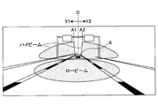
図3は、ヘッドランプ50のハイビームヘッドランプの照射範囲の制限態様の一例を示す図である。尚、図3は、前方環境画像により示される。図3に示すように、ヘッドランプ50の配光制御がオンであり、画像認識部42により他車両推定物体が検出される場合は、当該物体がハイビームヘッドランプにより照射されないようにハイビームヘッドランプの照射領域が制限される。図3に示す例では、ハイビームヘッドランプの照射領域は、水平方向の中心ラインOから左右方向(Y1・Y2方向)に広がる態様で制限される。具体的には、ハイビームヘッドランプの照射領域は、他車両推定物体Xの水平方向の位置に応じて、左側ハイビームヘッドランプの照射領域はラインA1(他車両推定物体の左端よりも左側のライン)まで制限され、右側ハイビームヘッドランプの照射領域はラインA2(他車両推定物体の右端よりも右側のライン)まで制限される。ここで、他車両推定物体Xの水平方向の位置は、画像認識部42により算出されてもよい。他車両推定物体Xの水平方向の位置(算出値)と、ランプシェードの位置、即ちハイビームヘッドランプの照射領域の制限位置(図示の例では、ラインA1,A2)との関係は、予め設計され、マップ形式で保存されてもよい。
FIG. 3 is a diagram showing an example of a restriction mode of the irradiation range of the high beam headlamp of the headlamp 50. FIG. 3 is shown by a front environment image. As shown in FIG. 3, when the light distribution control of the headlamp 50 is on and the other vehicle estimated object is detected by the image recognition unit 42, the high beam headlamp is controlled so that the object is not irradiated by the high beam headlamp. The irradiation area is limited. In the example shown in FIG. 3, the irradiation area of the high beam headlamp is limited in such a manner that it extends from the horizontal center line O in the left and right directions (Y1 and Y2 directions). Specifically, the irradiation area of the high beam headlamp is the line A1 (the line on the left side of the left end of the other vehicle estimation object) according to the horizontal position of the other vehicle estimation object X. The irradiation area of the right high beam headlamp is limited to line A2 (a line on the right side of the right end of the other vehicle estimated object). Here, the horizontal position of the other vehicle estimated object X may be calculated by the image recognition unit 42. The relationship between the horizontal position (calculated value) of the other vehicle estimated object X and the position of the lamp shade, that is, the limit position of the irradiation area of the high beam headlamp (lines A1 and A2 in the illustrated example) is designed in advance. , May be stored in a map format.
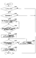
図4は、本実施例の制御ECU40により実行される主要処理の一例を示すフローチャートである。図4に示す処理は、車両のイグニッションスイッチがオンされた場合に起動されるものであってよい。
FIG. 4 is a flowchart showing an example of main processing executed by the control ECU 40 of this embodiment. The process shown in FIG. 4 may be started when the ignition switch of the vehicle is turned on.
ステップ402では、スイッチ20の状態に基づいて、ヘッドランプ50がオンであるか否かが判定される。ヘッドランプ50がオンである場合は、ステップ403に進み、ヘッドランプ50がオフである場合は、そのまま終了する。
In step 402, based on the state of the switch 20, it is determined whether or not the headlamp 50 is on. If the headlamp 50 is on, the process proceeds to step 403, and if the headlamp 50 is off, the process ends.
ステップ403では、スイッチ20の状態に基づいて、ヘッドランプ50の配光制御がオンであるか否かが判定される。ヘッドランプ50の配光制御がオンである場合は、ステップ404に進み、ヘッドランプ50の配光制御がオフである場合は、そのまま終了する。
In step 403, based on the state of the switch 20, it is determined whether or not the light distribution control of the headlamp 50 is on. If the light distribution control of the headlamp 50 is on, the process proceeds to step 404, and if the light distribution control of the headlamp 50 is off, the process ends.
尚、ステップ404以降の処理を実行する場合は、画像認識部42は、画像センサ10からリアルタイムで提供される前方環境画像を画像処理して、車両前方に存在しうる他車両(先行車や対向車)が存在するか否かを常に判定(追跡)する。ここでは、先行車が他車両推定物体として検出された場合を想定する。
In addition, when performing the process after step 404, the image recognition part 42 image-processes the front environment image provided in real time from the image sensor 10, and the other vehicle (preceding vehicle or opposite vehicle) which may exist ahead of a vehicle is processed. It is always determined (tracked) whether a vehicle is present. Here, it is assumed that the preceding vehicle is detected as the other vehicle estimated object.
ステップ404では、ランプシェード制御部46は、先行車がハイビームヘッドランプにより照射されないようにハイビームヘッドランプの照射領域を制限する。即ち、ランプシェード制御部46は、先行車が存在する領域以外をハイビームヘッドランプにより照射するようにハイビームヘッドランプの照射領域を制限する。図3に示した例では、上述の如く、ハイビームヘッドランプの照射領域は、他車両推定物体Xの水平方向の位置に応じて、左側ハイビームヘッドランプの照射領域がラインA1まで制限され、右側ハイビームヘッドランプの照射領域がラインA2まで制限される。これにより、他車両推定物体として検知された先行車においては、後方車両からのハイビームヘッドランプの照射を受けず、後方車両からのハイビームヘッドランプによる先行車の運転者の眩しさが防止される。尚、ラインA1、A2の位置は、随時更新される他車両推定物体X(図3に示した例では、先行車)の位置等の変化に応じて動的に変化されてもよい。
In step 404, the lamp shade controller 46 limits the irradiation area of the high beam headlamp so that the preceding vehicle is not irradiated by the high beam headlamp. That is, the lamp shade control unit 46 limits the irradiation area of the high beam headlamp so that the high beam headlamp irradiates the area other than the area where the preceding vehicle exists. In the example shown in FIG. 3, as described above, the irradiation area of the high beam headlamp is limited to the line A1 according to the horizontal position of the other vehicle estimated object X, and the right high beam The irradiation area of the headlamp is limited to line A2. As a result, the preceding vehicle detected as the other vehicle estimated object is not irradiated with the high beam headlamp from the rear vehicle, and glare of the driver of the preceding vehicle due to the high beam headlamp from the rear vehicle is prevented. The positions of the lines A1 and A2 may be dynamically changed according to changes in the position of the other vehicle estimated object X (a preceding vehicle in the example shown in FIG. 3) that is updated as needed.
ステップ405では、現在のハイビームヘッドランプの照射領域内に新たな他車両推定物体が画像認識部42において検出されたか否かが判定される。ハイビームヘッドランプの照射領域内に新たな車両推定物が検出された場合は、ステップ406に進み、それ以外の場合は、ステップ404に戻る。
In Step 405, it is determined whether or not a new other vehicle estimated object is detected in the image recognition unit 42 within the current irradiation region of the high beam headlamp. If a new vehicle estimate is detected within the irradiation area of the high beam headlamp, the process proceeds to step 406. Otherwise, the process returns to step 404.
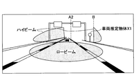
ステップ406では、ランプシェード制御部46は、新たな他車両推定物体がハイビームヘッドランプにより照射されないようにハイビームヘッドランプの照射領域を制限する。例えば、図5Aに示すように、路上の反射物(標識等の反射物)がハイビームヘッドランプの照射領域に入ると、当該反射物からの反射光が前方環境画像で捕捉される。この場合、画像認識部42は、当該反射光を発する物体(標識等の反射物)を新たな他車両推定物体X1として検出する場合がありうる。かかる場合は、ランプシェード制御部46は、図5Bに示すように、新たな他車両推定物体X1がハイビームヘッドランプにより照射されないようにハイビームヘッドランプの照射領域を制限する。具体的には、ハイビームヘッドランプの照射領域は、他車両推物体Xの水平方向の位置に応じて、右側ハイビームヘッドランプの照射領域がラインB(他車両推物体Xの右端よりも右側のライン)まで制限される。即ち、右側ハイビームヘッドランプの照射遮断領域が、ラインOからラインA2の間の領域(図5A参照)から、ラインOからラインBの間の領域(図5B参照)まで拡大される。尚、図5A及び図5Bは、前方環境画像により示される。
In step 406, the lamp shade control unit 46 limits the irradiation area of the high beam headlamp so that the new other vehicle estimated object is not irradiated by the high beam headlamp. For example, as shown in FIG. 5A, when a reflecting object (reflecting object such as a sign) on the road enters the irradiation region of the high beam headlamp, reflected light from the reflecting object is captured in the front environment image. In this case, the image recognition unit 42 may detect an object that emits the reflected light (a reflective object such as a sign) as a new other vehicle estimated object X1. In such a case, as shown in FIG. 5B, the lamp shade control unit 46 limits the irradiation area of the high beam headlamp so that the new other vehicle estimated object X1 is not irradiated by the high beam headlamp. Specifically, the irradiation area of the high beam headlamp is the line B (the line on the right side of the right end of the other vehicle thrust object X) according to the horizontal position of the other vehicle thrust object X. ). That is, the irradiation blocking region of the right high beam headlamp is expanded from the region between the line O and the line A2 (see FIG. 5A) to the region between the line O and the line B (see FIG. 5B). 5A and 5B are shown by the front environment image.
ステップ407では、画像認識部42において、上記ステップ405で検知された新たな他車両推定物体に係る像が画像センサ10の検出可能領域(カメラ画角)の外へ移動したか否かが判定される。この際、上記ステップ405で検知された新たな他車両推定物体に係る像は、時系列で連続的に得られる前方環境画像内で追尾されて特定されてもよいし、各前方環境画像に対して独立的に特定されてもよい。いずれにしても、上記ステップ405で検知された新たな他車両推定物体に係る像がカメラ画角外に至ると、前方環境画像内で、上記ステップ405で検知された新たな他車両推定物体に係る像が画像センサ10にて捕捉されなくなる。この場合は、ステップ409に進み、上記ステップ405で検知された新たな他車両推定物体に係る像が画像センサ10にて捕捉されている間は、ステップ408を経由して、ステップ407の処理を繰り返す。
In step 407, the image recognition unit 42 determines whether the image related to the new other vehicle estimated object detected in step 405 has moved outside the detectable area (camera angle of view) of the image sensor 10. The At this time, the image related to the new estimated other vehicle object detected in step 405 may be tracked and specified in the front environment image obtained continuously in time series, or for each front environment image. May be specified independently. In any case, when the image related to the new other vehicle estimated object detected in step 405 reaches outside the camera angle of view, the new other vehicle estimated object detected in step 405 is displayed in the front environment image. Such an image is not captured by the image sensor 10. In this case, the process proceeds to step 409, and while the image related to the new other vehicle estimated object detected in step 405 is captured by the image sensor 10, the process of step 407 is performed via step 408. repeat.
ここで、図5Aに示すように、路上の反射物(標識等の反射物)のような他車両以外の物体が、他車両推定物体として検出され、それにより、図5Bに示すように、新たな他車両推定物体X1がハイビームヘッドランプにより照射されないようにハイビームヘッドランプの照射領域が制限されると、新たな他車両推定物体X1として検出された物体がハイビームヘッドランプにより照射されなくなる。この結果、新たな他車両推定物体X1として検出された物体からの光(反射光)が実質的に無くなる(又は弱くなる)ので、その後の前方環境画像においては、当該新たな他車両推定物体X1として検出された物体は、他車両推定物体として画像認識部42により検出されることが無くなる。従って、本来であれば、新たな他車両推定物体X1として検出された物体が他車両推定物体として検出されなくなるので、上記ステップ406で拡大したハイビームヘッドランプの照射遮断領域を元の状態に減少させることになる。しかしながら、かかるハイビームヘッドランプの照射遮断領域の元の状態への復帰を実行すると、再び、同一の反射物が他車両推定物体として画像認識部42により検出されることになる。すると、再び、当該反射物がハイビームヘッドランプにより照射されないようにハイビームヘッドランプの照射領域が制限されることになる。このようにして、ハイビームヘッドランプの照射領域の拡大と減少が繰り返されると、先行車や対向車等の他車両の運転者に不快な眩惑を与えたり、パッシングと誤解されたりする虞があり、また、商品性の観点から望ましくない。
Here, as shown in FIG. 5A, an object other than the other vehicle such as a reflecting object (a reflecting object such as a sign) on the road is detected as the other vehicle estimated object, and as a result, as shown in FIG. If the irradiation area of the high beam headlamp is limited so that the other vehicle estimated object X1 is not irradiated by the high beam headlamp, the object detected as the new other vehicle estimated object X1 is not irradiated by the high beam headlamp. As a result, since the light (reflected light) from the object detected as the new other vehicle estimated object X1 is substantially eliminated (or weakened), in the subsequent forward environment image, the new other vehicle estimated object X1 The object detected as is no longer detected by the image recognition unit 42 as the other vehicle estimated object. Accordingly, since the object detected as the new other vehicle estimated object X1 is not detected as the other vehicle estimated object under normal circumstances, the irradiation blocking area of the high beam headlamp enlarged in step 406 is reduced to the original state. It will be. However, when the high-beam headlamp irradiation blockage area is restored to the original state, the same reflector is again detected by the image recognition unit 42 as the other vehicle estimated object. Then, the irradiation area of the high beam headlamp is limited again so that the reflector is not irradiated by the high beam headlamp. In this way, if the expansion and reduction of the irradiation area of the high beam headlamp are repeated, there is a risk of unpleasant dazzling to drivers of other vehicles such as preceding cars and oncoming cars, or misunderstood as passing, Moreover, it is not desirable from the viewpoint of merchantability.
そこで、本実施例では、かかる他車両推定物体として画像認識部42により検出される路上の反射物(標識等の反射物)に起因して、ハイビームヘッドランプの照射領域の拡大と減少が繰り返されるのを防止するロジックが組み込まれる。
Therefore, in the present embodiment, the irradiation area of the high beam headlamp is repeatedly expanded and decreased due to a reflection on the road (a reflection object such as a sign) detected by the image recognition unit 42 as the other vehicle estimation object. Built-in logic to prevent this.
具体的には、ステップ408では、上記ステップ406で拡大したハイビームヘッドランプの照射遮断領域を元の状態に減少させることが禁止される。即ち、右側ハイビームヘッドランプの照射遮断領域について、照射遮断境界ラインのラインBからラインA2方向への移動が禁止される。この場合、照射遮断境界ラインはラインBに維持されるが、ラインBの位置は、随時更新される他車両推定物体X1として検出された物体(図5Aに示した例では、路上の反射物)の位置等の変化に応じて動的に変化されてもよい。例えば、図5Aに示した例のように路上の反射物が固定物である場合は、前方環境画像において、車両の進行と共に当該反射物の像は右方向へと移動していく。これに伴い、ラインBについても前方環境画像における当該反射物の移動に応じて右方向へ移動されてもよい。ラインBの移動は、フィードバック的に実行されてもよい。例えば、ハイビームヘッドランプの照射領域ラインBは、車両の進行と共に反射物がハイビームヘッドランプにより再び照射される毎(他車両推定物体として画像認識部42により再び検出される毎に)にそれに応じて移動されてもよい。この場合は、車両の進行と共に反射物がハイビームヘッドランプにより再び照射されるまでの間は、ラインBは固定であり、車両の進行と共に反射物がハイビームヘッドランプにより再び照射される毎に、ラインBが外側へと移動していく。或いは、ラインBの移動は、フィードフォワード的に実行されてもよい。例えば、ステレオカメラ等により他車両推定物体X1として検出された物体の位置(図3に示した例では、路上の反射物の絶対位置又は相対位置)が算出可能である場合、当該他車両推定物体X1として検出された物体の位置に応じてラインBの位置(当該他車両推定物体X1として検出された物体がハイビームヘッドランプにより照射されないような位置)が決定されてもよい。また、車両の進行方向の変化(舵角センサから検出)や車両の速度や位置の変化(車速センサやGPS受信機から検出)に基づいて、ラインBの位置(他車両推定物体X1として検出された物体がハイビームヘッドランプにより照射されないような位置)が更新されてもよい。
Specifically, in step 408, it is prohibited to reduce the irradiation blocking area of the high beam headlamp enlarged in step 406 to the original state. That is, the movement of the irradiation blocking boundary line from the line B toward the line A2 is prohibited in the irradiation blocking area of the right high beam headlamp. In this case, the irradiation cutoff boundary line is maintained at the line B, but the position of the line B is an object detected as the other vehicle estimated object X1 that is updated as needed (in the example shown in FIG. 5A, a reflector on the road). The position may be dynamically changed according to the change in the position or the like. For example, when the reflecting object on the road is a fixed object as in the example shown in FIG. 5A, the image of the reflecting object moves to the right as the vehicle travels in the front environment image. Accordingly, the line B may also be moved in the right direction according to the movement of the reflecting object in the front environment image. The movement of line B may be performed in a feedback manner. For example, the irradiation area line B of the high beam headlamp corresponds to each time when the reflecting object is irradiated again by the high beam headlamp as the vehicle travels (every time the image recognition unit 42 detects again as another vehicle estimation object). It may be moved. In this case, the line B is fixed until the reflector is irradiated again by the high beam headlamp as the vehicle travels, and every time the reflector is irradiated again by the high beam headlamp as the vehicle travels, the line B is fixed. B moves outward. Alternatively, the movement of the line B may be executed in a feed forward manner. For example, when the position of the object detected as the other vehicle estimated object X1 by a stereo camera or the like (in the example shown in FIG. 3, the absolute position or the relative position of the reflecting object on the road) can be calculated, the other vehicle estimated object The position of the line B (a position where the object detected as the other vehicle estimated object X1 is not irradiated by the high beam headlamp) may be determined according to the position of the object detected as X1. Further, the position of the line B (detected as the other vehicle estimated object X1) based on the change in the vehicle traveling direction (detected from the steering angle sensor) and the change in the vehicle speed and position (detected from the vehicle speed sensor and GPS receiver). The position where the object is not illuminated by the high beam headlamp may be updated.
ステップ409では、上記ステップ406で拡大したハイビームヘッドランプの照射遮断領域を元の状態に減少させることが許可される。即ち、右側ハイビームヘッドランプの照射遮断領域について、照射遮断境界ラインのラインBからラインA2方向への移動が許可される。これにより、上記ステップ406で拡大したハイビームヘッドランプの照射遮断領域が元の状態(例えば図5Aの状態)に戻される。
In step 409, it is permitted to reduce the irradiation blocking area of the high beam headlamp enlarged in step 406 to the original state. That is, movement of the irradiation blocking boundary line from the line B toward the line A2 is permitted for the irradiation blocking region of the right high beam headlamp. As a result, the irradiation blocking area of the high beam headlamp enlarged in step 406 is returned to the original state (for example, the state shown in FIG. 5A).
このようにして、図4に示す処理によれば、路上の反射物(標識等の反射物)のような他車両以外の物体が、他車両推定物体として検出される場合であっても、それにより、当該他車両推定物体がハイビームヘッドランプにより照射されないようにハイビームヘッドランプの照射領域が制限されるが、当該制限後、当該他車両推定物体として検出された物体が他車両推定物体として検出されない場合でも、ハイビームヘッドランプの照射領域の制限は、当該他車両推定物体として検出された物体に係る像がカメラ画角外に出るまで維持されるので、ハイビームヘッドランプの照射領域の拡大と減少の繰り返しを効果的に防止することができる。
Thus, according to the process shown in FIG. 4, even if an object other than another vehicle such as a reflector (a reflector such as a sign) on the road is detected as the other vehicle estimated object, Therefore, the irradiation area of the high beam headlamp is limited so that the other vehicle estimated object is not irradiated by the high beam headlamp, but after the limitation, the object detected as the other vehicle estimated object is not detected as the other vehicle estimated object. Even in this case, the limitation on the irradiation area of the high beam headlamp is maintained until the image related to the object detected as the other vehicle estimated object comes out of the camera angle of view. Repeating can be effectively prevented.
図6は、本実施例の制御ECU40により実行される主要処理のその他の一例を示すフローチャートである。図6に示す処理は、車両のイグニッションスイッチがオンされた場合に起動されるものであってよい。
FIG. 6 is a flowchart showing another example of the main process executed by the control ECU 40 of this embodiment. The process shown in FIG. 6 may be started when the ignition switch of the vehicle is turned on.
図6のステップ507以外のステップは、図4の対応するステップとそれぞれ実質的に同一であってよい。このため、ここでは、ステップ507の処理について説明する。
Steps other than step 507 in FIG. 6 may be substantially the same as the corresponding steps in FIG. For this reason, the process of step 507 is demonstrated here.
ステップ507では、ステップ506で実行したハイビームヘッドランプの照射遮断領域の拡大処理時点から所定の遅延時間が経過したか否かが判定される。所定の遅延時間は、当然ながら画像認識部42による画像認識処理サイクルよりも十分に長い時間である。所定の遅延時間は、理想的には、ステップ505で検知された新たな他車両推定物体に係る像がカメラ画角外に消えるまでの時間に対応し、所定の固定時間であってよい。或いは、所定の遅延時間は、可変時間であってよく、この場合、典型的な路上の反射物(標識等の反射物)が画像認識部42により他車両推定物体として検出されるときの当該路上の反射物と車両との距離の試験データ又は予測値が考慮されてもよい。この場合、所定の遅延時間は、当該距離を車速(現在車速又は平均車速等)で割り算した時間相当であってもよい。或いは、ステレオカメラ等により他車両推定物体X1として検出された物体の位置(図3に示した例では、路上の反射物の絶対位置又は相対位置)が算出可能である場合、当該他車両推定物体X1として検出された物体の位置(自車両との距離)に応じて所定の遅延時間を設定してもよい。この場合、所定の遅延時間は、他車両推定物体X1として検出された物体と自車両との間の距離を車速(現在車速又は平均車速等)で割り算した時間相当であってもよい。
In step 507, it is determined whether or not a predetermined delay time has elapsed since the time of enlargement processing of the irradiation blocking area of the high beam headlamp executed in step 506. Naturally, the predetermined delay time is sufficiently longer than the image recognition processing cycle by the image recognition unit 42. The predetermined delay time ideally corresponds to the time until the image related to the new other vehicle estimated object detected in step 505 disappears outside the camera angle of view, and may be a predetermined fixed time. Alternatively, the predetermined delay time may be a variable time. In this case, a typical road reflection object (a reflection object such as a sign) is detected on the road when the image recognition unit 42 detects the other vehicle estimation object. Test data or predicted values of the distance between the reflector and the vehicle may be taken into account. In this case, the predetermined delay time may be equivalent to a time obtained by dividing the distance by the vehicle speed (current vehicle speed or average vehicle speed or the like). Alternatively, when the position of the object detected as the other vehicle estimated object X1 by a stereo camera or the like (in the example shown in FIG. 3, the absolute position or the relative position of the reflecting object on the road) can be calculated, the other vehicle estimated object A predetermined delay time may be set according to the position of the object detected as X1 (distance from the host vehicle). In this case, the predetermined delay time may be equivalent to a time obtained by dividing the distance between the object detected as the other vehicle estimated object X1 and the host vehicle by the vehicle speed (current vehicle speed, average vehicle speed, or the like).
このようにして、図6に示す処理によれば、路上の反射物(標識等の反射物)のような他車両以外の物体が、他車両推定物体として検出される場合であっても、それにより、当該他車両推定物体がハイビームヘッドランプにより照射されないようにハイビームヘッドランプの照射領域が制限されるが、当該制限が所定の遅延時間維持されるので、ハイビームヘッドランプの照射領域の拡大と減少の繰り返しを効果的に抑制することができる。
Thus, according to the processing shown in FIG. 6, even if an object other than another vehicle such as a reflector (a reflector such as a sign) on the road is detected as the other vehicle estimated object, Therefore, the irradiation area of the high beam headlamp is limited so that the other vehicle estimated object is not irradiated by the high beam headlamp, but the limitation is maintained for a predetermined delay time, so that the irradiation area of the high beam headlamp is expanded and decreased. Can be effectively suppressed.
図7は、本実施例の制御ECU40により実行される主要処理のその他の一例を示すフローチャートである。図7に示す処理は、車両のイグニッションスイッチがオンされた場合に起動されるものであってよい。
FIG. 7 is a flowchart showing another example of the main process executed by the control ECU 40 of this embodiment. The process shown in FIG. 7 may be started when the ignition switch of the vehicle is turned on.
図7のステップ602-606は、図4の対応するステップ402-406とそれぞれ実質的に同一であってよい。このため、ここでは、図7に特有の処理について説明する。
Steps 602-606 in FIG. 7 may be substantially the same as the corresponding steps 402-406 in FIG. For this reason, the processing peculiar to FIG. 7 will be described here.
ステップ607では、画像認識部42において、ステップ605で検知された新たな他車両推定物体が、他車両であるか又は他車両以外の反射物であるかが再判定される(ハイビームヘッドランプの照射領域のラインBへの拡大後に再判定される)。ここで、ステップ605で検知された新たな他車両推定物体が実際に他車両であれば、他車両自身が発光していることにより他車両推定物体として検出されていることから、当該他車両推定物体がハイビームヘッドランプにより照射されないようにハイビームヘッドランプの照射領域を制限しても、画像認識部42において依然として他車両推定物体として検出され続けることになる。他方、ステップ605で検知された新たな他車両推定物体が実際に他車両でなければ(即ち他車両以外の反射物であれば)、自身が発光しているわけでないことから、当該他車両推定物体がハイビームヘッドランプにより照射されないようにハイビームヘッドランプの照射領域を制限すると、画像認識部42において他車両推定物体として検出されなくなる。従って、この相違を利用して、ステップ605で検知された新たな他車両推定物体が、他車両であるか又は他車両以外の反射物であるかが判定されてもよい。ステップ605で検知された新たな他車両推定物体が他車両である場合は、ステップ604に戻り、ステップ604では、ランプシェード制御部46は、先行車及び新たな他車両推定物体がハイビームヘッドランプにより照射されないようにハイビームヘッドランプの照射領域を制限する。他方、ステップ605で検知された新たな他車両推定物体が他車両で無い場合は(即ち他車両以外の反射物である場合は)、ステップ609に進む。
In step 607, the image recognition unit 42 determines again whether the new other vehicle estimated object detected in step 605 is another vehicle or a reflector other than the other vehicle (irradiation of the high beam headlamp). It is determined again after the area is expanded to line B). Here, if the new other vehicle estimated object detected in step 605 is actually another vehicle, it is detected as the other vehicle estimated object because the other vehicle itself emits light. Even if the irradiation area of the high beam headlamp is limited so that the object is not irradiated by the high beam headlamp, the image recognition unit 42 continues to detect the other vehicle estimated object. On the other hand, if the new other vehicle estimated object detected in step 605 is not actually another vehicle (that is, if it is a reflector other than the other vehicle), the other vehicle estimated is not emitted. When the irradiation area of the high beam headlamp is limited so that the object is not irradiated by the high beam headlamp, the image recognition unit 42 does not detect the other vehicle estimated object. Therefore, using this difference, it may be determined whether the new other vehicle estimated object detected in step 605 is another vehicle or a reflector other than the other vehicle. If the new other vehicle estimated object detected in step 605 is another vehicle, the process returns to step 604. In step 604, the lamp shade control unit 46 determines that the preceding vehicle and the new other vehicle estimated object are high beam headlamps. The irradiation area of the high beam headlamp is limited so as not to be irradiated. On the other hand, if the new other vehicle estimated object detected in step 605 is not another vehicle (that is, if it is a reflector other than the other vehicle), the process proceeds to step 609.
ステップ609では、上記ステップ606で拡大したハイビームヘッドランプの照射遮断領域を元の状態に減少させることが許可される。即ち、右側ハイビームヘッドランプの照射遮断領域について、照射遮断境界ラインのラインBからラインA2方向への移動が許可される。但し、この場合、以後、ステップ607で判別された非他車両は、例外的に、他車両推定物体として扱われない。即ち、通常であれば、ステップ609にてハイビームヘッドランプの照射遮断領域を元の状態に減少させると、ステップ607で判別された非他車両が再びハイビームヘッドランプの照射を受け、画像認識部42において、他車両推定物体として再び検出されることになる。しかしながら、本実施例では、画像認識部42において、ステップ607で判別された非他車両については、該非他車両に係る像が前方環境画像中で追跡されている間、該非他車両に係る像が他車両推定物体の検出条件を満たした場合でも、他車両推定物体として検出しない。
In step 609, it is permitted to reduce the irradiation blocking area of the high beam headlamp enlarged in step 606 to the original state. That is, movement of the irradiation blocking boundary line from the line B toward the line A2 is permitted for the irradiation blocking region of the right high beam headlamp. However, in this case, the non-other vehicle determined in step 607 is not treated as an other vehicle estimated object. That is, under normal circumstances, when the irradiation blocking area of the high beam headlamp is reduced to the original state in step 609, the non-other vehicle determined in step 607 is again irradiated with the high beam headlamp, and the image recognition unit 42 In this case, it is detected again as the other vehicle estimated object. However, in this embodiment, for the non-other vehicle determined in step 607 in the image recognition unit 42, the image related to the non-other vehicle is displayed while the image related to the non-other vehicle is being tracked in the forward environment image. Even when the detection condition of the other vehicle estimated object is satisfied, it is not detected as the other vehicle estimated object.
このようにして、図7に示す処理によれば、路上の反射物(標識等の反射物)のような他車両以外の物体が、他車両推定物体として検出される場合、当該他車両推定物体がハイビームヘッドランプにより照射されないようにハイビームヘッドランプの照射領域が制限される。そして、当該制限後の画像認識処理により、他車両推定物体として検出された物体が、他車両でないと判断できる場合には、当該制限を解除しつつ、以後、当該他車両以外の物体を、他車両推定物体として再度検出しないようにマスクする。これにより、ハイビームヘッドランプの照射領域の拡大と減少の繰り返しを効果的に防止することができる。尚、図7に示す処理によれば、標識のような他車両以外の物体に対しては、一旦、ハイビームヘッドランプにより照射されないようにハイビームヘッドランプの照射領域が制限された後、直ぐに当該制限が解除され、ハイビームヘッドランプにより照射される状態が継続するが、標識のような他車両以外の物体は他車両でないため、他車両の運転者に眩しさを与える等の不都合は生じない。
Thus, according to the process shown in FIG. 7, when an object other than another vehicle such as a reflector (a reflector such as a sign) on the road is detected as the other vehicle estimated object, the other vehicle estimated object The irradiation area of the high beam headlamp is limited so that is not irradiated by the high beam headlamp. Then, if it can be determined that the object detected as the other vehicle estimated object is not another vehicle by the image recognition process after the restriction, the object other than the other vehicle is changed to another while releasing the restriction. Mask not to be detected again as a vehicle estimation object. Thereby, it is possible to effectively prevent the enlargement and reduction of the irradiation area of the high beam headlamp. In addition, according to the process shown in FIG. 7, once the irradiation area of the high beam headlamp is limited so that the object other than the other vehicle such as a sign is not irradiated by the high beam headlamp, the restriction is immediately performed. Is released and the state of irradiation by the high beam headlamp continues, but since an object other than the other vehicle such as a sign is not the other vehicle, there is no inconvenience such as giving glare to the driver of the other vehicle.
以上、好ましい実施例について詳説したが、本発明は、上述した実施例に制限されることはなく、本発明の範囲を逸脱することなく、上述した実施例に種々の変形及び置換を加えることができる。
The preferred embodiments have been described in detail above, but the present invention is not limited to the above-described embodiments, and various modifications and substitutions can be made to the above-described embodiments without departing from the scope of the present invention. it can.
例えば、上述した実施例では、ハイビームヘッドランプの照射領域に関するものであるが、ロービームヘッドランプの照射領域に関しても同様に適用可能である。例えば、ロービームヘッドランプについては、路面上に付着又は載置される反射物に起因した照射領域の拡大と減少の繰り返しを効果的に防止することができる。
For example, in the above-described embodiment, it relates to the irradiation region of the high beam headlamp, but it can be similarly applied to the irradiation region of the low beam headlamp. For example, in the case of a low beam headlamp, it is possible to effectively prevent the irradiation area from being repeatedly enlarged and reduced due to a reflector attached to or placed on the road surface.
また、上述した実施例では、画像センサ10から得られる前方環境画像のみを用いて他車両推定物体を検出しているが、他の情報を追加的に利用して、他車両推定物体を検出することも可能である。例えば、ミリ波レーダ、レーザーレーダ等のような各種レーダ装置からの他車両情報(他車両の存在、位置、速度等)、車車間通信により得られる他車両情報(他車両の存在、位置、速度等)等を利用して、他車両推定物体を検出することも可能である。
In the above-described embodiment, the other vehicle estimated object is detected using only the front environment image obtained from the image sensor 10, but other information is additionally used to detect the other vehicle estimated object. It is also possible. For example, other vehicle information (existence, position, speed, etc. of other vehicles) from various radar devices such as millimeter wave radar, laser radar, etc., other vehicle information (existence, position, speed of other vehicles) obtained by inter-vehicle communication It is also possible to detect the other vehicle estimated object using the above.
また、上述した実施例では、ハイビームヘッドランプの照射領域は、図3等に示すように、水平方向の中心ラインOから左右方向(Y1・Y2方向)に広がる態様で制限されているが(図3参照)、ハイビームヘッドランプの照射領域の制限態様は任意であってよい。例えば、図5Bに示したようなハイビームヘッドランプの照射領域の制限態様に代えて、図8に示すように、ラインB3(他車両推定物体の左端よりも左側のライン)から外側(右側)が照射されないように制限してもよい。即ち、水平方向の中心ラインOからのラインA2の移動と、水平方向の最外側のラインGからのラインB3の移動とにより双方向からハイビームヘッドランプの照射領域を制限してもよい。尚、図8は、前方環境画像により示される。
Further, in the above-described embodiment, the irradiation area of the high beam headlamp is limited in such a manner as to extend from the horizontal center line O to the left and right directions (Y1 and Y2 directions) as shown in FIG. 3), the mode of limiting the irradiation area of the high beam headlamp may be arbitrary. For example, instead of the restriction mode of the irradiation region of the high beam headlamp as shown in FIG. 5B, as shown in FIG. 8, the outside (right side) from the line B3 (the line on the left side of the left end of the other vehicle estimated object) You may restrict | limit so that it may not be irradiated. That is, the irradiation area of the high beam headlamp may be limited from both directions by moving the line A2 from the horizontal center line O and moving the line B3 from the outermost line G in the horizontal direction. FIG. 8 is shown by a front environment image.
また、上述した実施例では、ハイビームヘッドランプの照射領域は、水平方向で可変されているが、それに代えて若しくは加えて、鉛直方向(上下方向)で可変されてもよい。例えば、上下方向の場合、車道の真上に設置される道路標識などの反射物に起因した照射領域の拡大と減少の繰り返しを効果的に防止することができる。
In the above-described embodiments, the irradiation area of the high beam headlamp is varied in the horizontal direction, but may be varied in the vertical direction (up and down direction) instead of or in addition thereto. For example, in the case of the up and down direction, it is possible to effectively prevent repeated enlargement and reduction of the irradiation area due to a reflector such as a road sign installed just above the roadway.
1 車両配光制御装置
10 画像センサ
20 スイッチ
30 車両情報取得部
40 制御ECU
42 画像認識部
44 ヘッドランプ制御部
46 ランプシェード制御部
50 ヘッドランプ
51 ヘッドランプ部
52 ランプシェード部 DESCRIPTION OFSYMBOLS 1 Vehicle light distribution control apparatus 10 Image sensor 20 Switch 30 Vehicle information acquisition part 40 Control ECU
42Image recognition unit 44 Head lamp control unit 46 Lamp shade control unit 50 Head lamp 51 Head lamp unit 52 Lamp shade unit
10 画像センサ
20 スイッチ
30 車両情報取得部
40 制御ECU
42 画像認識部
44 ヘッドランプ制御部
46 ランプシェード制御部
50 ヘッドランプ
51 ヘッドランプ部
52 ランプシェード部 DESCRIPTION OF
42
Claims (8)
- 車両配光制御装置であって、
車両前方を撮影するカメラと、
車両前方に照明光を照射する照明装置と、
前記カメラで得られる画像中における所定条件を満たす像を、他車両と推定される物体として検出すると共に、該検出結果に基づいて、前記照明光の配光を制御する制御装置とを備え、
前記制御装置は、前記照明光の照射領域内に他車両と推定される物体を検出した場合は、前記他車両と推定される物体が前記照明光により照射されないように前記照明光の照射領域を制限し、該制限による前記照明光の非照射領域内に他車両と推定される物体を検出しない場合は、所定の解除条件が成立するまで前記照明光の照射領域の制限の解除を抑制するように構成されることを特徴とする、車両配光制御装置。 A vehicle light distribution control device,
A camera that captures the front of the vehicle,
An illumination device for irradiating illumination light in front of the vehicle;
An image that satisfies a predetermined condition in an image obtained by the camera is detected as an object estimated as another vehicle, and a control device that controls light distribution of the illumination light based on the detection result,
When the control device detects an object estimated to be another vehicle in the illumination light irradiation region, the control device sets the illumination light irradiation region so that the object estimated to be the other vehicle is not irradiated by the illumination light. In a case where an object estimated as another vehicle is not detected in the non-irradiation area of the illumination light due to the restriction, the release of the restriction of the illumination light irradiation area is suppressed until a predetermined release condition is satisfied. A vehicle light distribution control device comprising: - 前記所定の解除条件は、前記他車両と推定される物体として検出された物体が、前記カメラの画角範囲内から消失することである、請求項1に記載の車両配光制御装置。 2. The vehicle light distribution control device according to claim 1, wherein the predetermined release condition is that an object detected as an object estimated to be the other vehicle disappears from an angle of view range of the camera.
- 前記所定の解除条件は、前記照明光の照射領域を制限した時点から一定の時間が経過することである、請求項1に記載の車両配光制御装置。 The vehicle light distribution control device according to claim 1, wherein the predetermined release condition is that a certain time elapses from a time point when the illumination light irradiation area is limited.
- 前記照明光は、ハイビームである、請求項1に記載の車両配光制御装置。 The vehicle light distribution control device according to claim 1, wherein the illumination light is a high beam.
- 前記他車両と推定される物体は、前記カメラにより撮像した画像中における像の明るさ、像の動き及び像の色のうちの少なくともいずれかの特徴に基づいて検出される、請求項1に記載の車両配光制御装置。 The object estimated as the other vehicle is detected based on at least one of the characteristics of image brightness, image motion, and image color in an image captured by the camera. Vehicle light distribution control device.
- 車両配光制御装置であって、
車両前方を撮影するカメラと、
車両前方に照明光を照射する照明装置と、
前記カメラで得られる画像中における所定条件を満たす像を、他車両と推定される物体として検出すると共に、該検出結果に基づいて、前記照明光の配光を制御する制御装置とを備え、
前記制御装置は、前記照明光の照射領域内に他車両と推定される物体を検出した場合は、前記他車両と推定される物体が前記照明光により照射されないように前記照明光の照射領域を制限し、該制限による前記照明光の非照射領域内に他車両と推定される物体を検出しない場合は、前記照明光の照射領域の制限を解除する配光制御を実行するように構成され、
前記制御装置は、他車両と推定される物体として誤検出しうる非他車両に起因した前記照明光の照射領域の制限と解除の繰り返しが抑制される態様で、前記配光制御を実行するように構成されることを特徴とする、車両配光制御装置。 A vehicle light distribution control device,
A camera that captures the front of the vehicle,
An illumination device for irradiating illumination light in front of the vehicle;
An image that satisfies a predetermined condition in an image obtained by the camera is detected as an object estimated as another vehicle, and a control device that controls light distribution of the illumination light based on the detection result,
When the control device detects an object estimated to be another vehicle in the illumination light irradiation region, the control device sets the illumination light irradiation region so that the object estimated to be the other vehicle is not irradiated by the illumination light. Limiting and not detecting an object that is estimated to be another vehicle in the non-irradiation area of the illumination light due to the restriction, and is configured to execute light distribution control for releasing the restriction of the irradiation area of the illumination light,
The control device is configured to execute the light distribution control in a manner in which repetition of restriction and release of the illumination light irradiation area caused by a non-other vehicle that may be erroneously detected as an object estimated as another vehicle is suppressed. A vehicle light distribution control device comprising: - 前記制御装置は、前記照明光の照射領域内に他車両と推定される物体を検出した場合は、前記他車両と推定される物体が前記照明光により照射されないように前記照明光の照射領域を制限し、該制限による前記照明光の非照射領域内に他車両と推定される物体を検出しない場合は、前記照明光の照射領域の制限を解除し、該解除後に、前記他車両と推定される物体として検出された物体に係る像が前記所定条件を満たす場合でも、該物体に係る像に対する前記照明光の照射領域の制限を禁止するように構成される、請求項6に記載の車両配光制御装置。 When the control device detects an object estimated to be another vehicle in the illumination light irradiation region, the control device sets the illumination light irradiation region so that the object estimated to be the other vehicle is not irradiated by the illumination light. If the object that is estimated to be another vehicle is not detected in the illumination light non-irradiation area due to the restriction, the restriction of the illumination light irradiation area is canceled, and after the release, the other vehicle is estimated. 7. The vehicle arrangement according to claim 6, wherein the vehicle arrangement is configured to prohibit the irradiation area of the illumination light on the image relating to the object even when the image relating to the object detected as the object satisfies the predetermined condition. Light control device.
- 車両配光制御方法であって、
車両前方を撮影するカメラからの画像を取得し、
照明装置により車両前方に照明光を照射し、
前記カメラで得られる画像中における所定条件を満たす像を、他車両と推定される物体として検出し、
前記照明光の照射領域内に他車両と推定される物体を検出した場合に、前記他車両と推定される物体が前記照明光により照射されないように前記照明光の照射領域を制限し、
前記照明光の照射領域を制限した後、該制限による前記照明光の非照射領域内に前記他車両と推定される物体を検出しない場合に、所定の解除条件が成立するまで前記照明光の照射領域の制限の解除を抑制することを含むことを特徴とする、車両配光制御方法。 A vehicle light distribution control method,
Get an image from the camera that captures the front of the vehicle,
Illuminate the front of the vehicle with the illumination device,
Detecting an image satisfying a predetermined condition in an image obtained by the camera as an object presumed to be another vehicle,
When an object estimated to be another vehicle is detected within the illumination light irradiation area, the illumination light irradiation area is limited so that the object estimated to be the other vehicle is not irradiated by the illumination light,
Irradiation of the illumination light until a predetermined release condition is satisfied when an object estimated to be the other vehicle is not detected in the illumination light non-irradiation region due to the restriction after the illumination light irradiation region is limited A vehicle light distribution control method comprising suppressing release of restriction of a region.
Priority Applications (5)
| Application Number | Priority Date | Filing Date | Title |
|---|---|---|---|
| CN201080068121.XA CN103249597B (en) | 2010-08-06 | 2010-08-06 | Vehicle light distribution control device and method |
| US13/696,731 US8827514B2 (en) | 2010-08-06 | 2010-08-06 | Vehicle light distribution control apparatus and method |
| PCT/JP2010/063423 WO2012017559A1 (en) | 2010-08-06 | 2010-08-06 | Vehicle light distribution control device and method |
| EP10855648.1A EP2602154B1 (en) | 2010-08-06 | 2010-08-06 | Vehicle light distribution control device and method |
| JP2012527526A JP5413511B2 (en) | 2010-08-06 | 2010-08-06 | Vehicle light distribution control device and method |
Applications Claiming Priority (1)
| Application Number | Priority Date | Filing Date | Title |
|---|---|---|---|
| PCT/JP2010/063423 WO2012017559A1 (en) | 2010-08-06 | 2010-08-06 | Vehicle light distribution control device and method |
Publications (1)
| Publication Number | Publication Date |
|---|---|
| WO2012017559A1 true WO2012017559A1 (en) | 2012-02-09 |
Family
ID=45559089
Family Applications (1)
| Application Number | Title | Priority Date | Filing Date |
|---|---|---|---|
| PCT/JP2010/063423 WO2012017559A1 (en) | 2010-08-06 | 2010-08-06 | Vehicle light distribution control device and method |
Country Status (5)
| Country | Link |
|---|---|
| US (1) | US8827514B2 (en) |
| EP (1) | EP2602154B1 (en) |
| JP (1) | JP5413511B2 (en) |
| CN (1) | CN103249597B (en) |
| WO (1) | WO2012017559A1 (en) |
Cited By (5)
| Publication number | Priority date | Publication date | Assignee | Title |
|---|---|---|---|---|
| WO2013172398A1 (en) * | 2012-05-16 | 2013-11-21 | 株式会社デンソー | Device for detecting vehicle light and method therefor |
| CN104220299A (en) * | 2012-03-28 | 2014-12-17 | 株式会社电装 | Light control device and light control program |
| JP2019172105A (en) * | 2018-03-28 | 2019-10-10 | ダイハツ工業株式会社 | Light distribution controller |
| CN111791796A (en) * | 2019-04-08 | 2020-10-20 | 丰田自动车株式会社 | Headlamp control device for vehicle |
| WO2021002297A1 (en) * | 2019-07-03 | 2021-01-07 | 株式会社小糸製作所 | Vehicular lighting system, vehicle system and vehicle |
Families Citing this family (22)
| Publication number | Priority date | Publication date | Assignee | Title |
|---|---|---|---|---|
| WO2012137332A1 (en) | 2011-04-07 | 2012-10-11 | パイオニア株式会社 | System for detecting surrounding conditions of moving body |
| DE102011055606A1 (en) * | 2011-11-22 | 2013-05-23 | Hella Kgaa Hueck & Co. | Method and control unit for controlling headlamps with adjustable vertical light-dark boundary for deblading objects |
| KR101360344B1 (en) * | 2012-02-17 | 2014-02-10 | 현대모비스 주식회사 | Control apparatus and method of a vehicle lamp |
| EP3020602B1 (en) * | 2013-07-11 | 2024-04-10 | Koito Manufacturing Co., Ltd. | Light distribution control method and light distribution control device for vehicular head lamp |
| JP6264909B2 (en) * | 2014-01-31 | 2018-01-24 | 株式会社デンソー | Headlamp control device and headlamp |
| JP6599613B2 (en) | 2014-12-25 | 2019-10-30 | 株式会社小糸製作所 | Light distribution variable vehicle lamp |
| AT517415B1 (en) * | 2015-06-29 | 2017-04-15 | Zkw Group Gmbh | Control device for a lighting device of a motor vehicle and method for controlling such a lighting device |
| JP6558228B2 (en) * | 2015-11-30 | 2019-08-14 | 株式会社Jvcケンウッド | Headlight device, headlight control method, and headlight control program |
| WO2018117631A1 (en) * | 2016-12-21 | 2018-06-28 | Samsung Electronics Co., Ltd. | Electronic apparatus and method of operating the same |
| DE102017200574B4 (en) * | 2017-01-16 | 2019-12-12 | Robert Bosch Gmbh | Method for monitoring an environment of a vehicle |
| KR101908423B1 (en) * | 2017-04-10 | 2018-10-16 | 엘지전자 주식회사 | Vehicle control device mounted on vehicle and vheicle control method thereof |
| US11525688B2 (en) | 2017-12-15 | 2022-12-13 | Samsung Electronics Co., Ltd. | Method and apparatus for determining object position |
| KR102521656B1 (en) | 2018-01-03 | 2023-04-13 | 삼성전자주식회사 | Method and apparatus of identifying object |
| KR102541561B1 (en) | 2018-02-12 | 2023-06-08 | 삼성전자주식회사 | Method of providing information for driving vehicle and apparatus thereof |
| JP7046734B2 (en) * | 2018-06-27 | 2022-04-04 | 矢崎総業株式会社 | Car interior lighting system |
| US11066006B2 (en) | 2018-08-06 | 2021-07-20 | Koito Manufacturing Co., Ltd. | Vehicle lamp |
| JP7252755B2 (en) * | 2018-12-27 | 2023-04-05 | 株式会社小糸製作所 | Active sensors, object identification systems, vehicles, vehicle lighting |
| US11300974B2 (en) * | 2019-07-18 | 2022-04-12 | GM Global Technology Operations LLC | Perception methods and systems for low lighting conditions |
| JP7152703B2 (en) * | 2019-09-03 | 2022-10-13 | トヨタ自動車株式会社 | Vehicle lighting device |
| CN114312550A (en) * | 2021-12-28 | 2022-04-12 | 北京梧桐车联科技有限责任公司 | Control method, device and equipment of vehicle headlamp and storage medium |
| US20230309207A1 (en) * | 2022-03-25 | 2023-09-28 | Microsoft Technology Licensing, Llc | Illumination light control based on orientation |
| US11590880B1 (en) * | 2022-05-13 | 2023-02-28 | Rivian Ip Holdings, Llc | Predictive illumination shaping |
Citations (4)
| Publication number | Priority date | Publication date | Assignee | Title |
|---|---|---|---|---|
| JPH0210141U (en) * | 1988-07-04 | 1990-01-23 | ||
| WO2008037388A2 (en) | 2006-09-27 | 2008-04-03 | Volkswagen Aktiengesellschaft | Headlight arrangement for a vehicle and method for controlling a headlight arrangement |
| JP2009211963A (en) | 2008-03-05 | 2009-09-17 | Koito Mfg Co Ltd | Vehicular lamp |
| JP2010162960A (en) * | 2009-01-13 | 2010-07-29 | Koito Mfg Co Ltd | Vehicle headlight device |
Family Cites Families (12)
| Publication number | Priority date | Publication date | Assignee | Title |
|---|---|---|---|---|
| JPS62253545A (en) | 1986-04-25 | 1987-11-05 | Mazda Motor Corp | Automatic light controller for vehicle |
| US6587573B1 (en) * | 2000-03-20 | 2003-07-01 | Gentex Corporation | System for controlling exterior vehicle lights |
| JP4466604B2 (en) | 2006-04-26 | 2010-05-26 | 株式会社デンソー | Vehicle headlamp device |
| JP4484856B2 (en) * | 2006-10-06 | 2010-06-16 | 日立オートモティブシステムズ株式会社 | Automotive headlight controller |
| JP4349414B2 (en) * | 2006-12-15 | 2009-10-21 | トヨタ自動車株式会社 | Vehicle lighting device |
| FR2911206B1 (en) * | 2006-12-21 | 2009-05-08 | Valeo Vision Sa | METHOD FOR AUTOMATIC DISCRIMINATION OF LIGHT AREAS DETECTED BY A DRIVING DEVICE FOR VEHICLE. |
| JP4538468B2 (en) * | 2007-02-27 | 2010-09-08 | 日立オートモティブシステムズ株式会社 | Image processing apparatus, image processing method, and image processing system |
| JP4970145B2 (en) * | 2007-05-30 | 2012-07-04 | 株式会社小糸製作所 | Vehicle headlamp |
| JP2009179113A (en) * | 2008-01-29 | 2009-08-13 | Koito Mfg Co Ltd | Head lamp device for vehicle and its control method |
| JP2009214812A (en) * | 2008-03-12 | 2009-09-24 | Koito Mfg Co Ltd | Vehicular headlight device and its control method |
| JP2009220649A (en) * | 2008-03-14 | 2009-10-01 | Koito Mfg Co Ltd | Headlamp device for vehicle |
| DE102008059630A1 (en) * | 2008-11-28 | 2010-06-02 | Adc Automotive Distance Control Systems Gmbh | Method for detecting vehicle lights and retroreflectors with a camera system |
-
2010
- 2010-08-06 US US13/696,731 patent/US8827514B2/en active Active
- 2010-08-06 CN CN201080068121.XA patent/CN103249597B/en active Active
- 2010-08-06 WO PCT/JP2010/063423 patent/WO2012017559A1/en active Application Filing
- 2010-08-06 JP JP2012527526A patent/JP5413511B2/en active Active
- 2010-08-06 EP EP10855648.1A patent/EP2602154B1/en active Active
Patent Citations (4)
| Publication number | Priority date | Publication date | Assignee | Title |
|---|---|---|---|---|
| JPH0210141U (en) * | 1988-07-04 | 1990-01-23 | ||
| WO2008037388A2 (en) | 2006-09-27 | 2008-04-03 | Volkswagen Aktiengesellschaft | Headlight arrangement for a vehicle and method for controlling a headlight arrangement |
| JP2009211963A (en) | 2008-03-05 | 2009-09-17 | Koito Mfg Co Ltd | Vehicular lamp |
| JP2010162960A (en) * | 2009-01-13 | 2010-07-29 | Koito Mfg Co Ltd | Vehicle headlight device |
Non-Patent Citations (2)
| Title |
|---|
| BERND DREIER; ERNST-OLAF ROSENHAHN: "Camera Controlled Adaptive Cut-off and Adaptive Partial High Beam Applications", 8TH INTERNATIONAL SYMPOSIUM ON AUTOMOTIVE LIGHTING 2009 VERSION 13, 2009 |
| See also references of EP2602154A4 |
Cited By (11)
| Publication number | Priority date | Publication date | Assignee | Title |
|---|---|---|---|---|
| CN104220299A (en) * | 2012-03-28 | 2014-12-17 | 株式会社电装 | Light control device and light control program |
| US10279729B2 (en) | 2012-03-28 | 2019-05-07 | Denso Corporation | Light control device and light control program |
| WO2013172398A1 (en) * | 2012-05-16 | 2013-11-21 | 株式会社デンソー | Device for detecting vehicle light and method therefor |
| JP2013237389A (en) * | 2012-05-16 | 2013-11-28 | Denso Corp | Lamplight detecting device and vehicle control system |
| JP2019172105A (en) * | 2018-03-28 | 2019-10-10 | ダイハツ工業株式会社 | Light distribution controller |
| JP7055563B2 (en) | 2018-03-28 | 2022-04-18 | ダイハツ工業株式会社 | Light distribution control device |
| CN111791796A (en) * | 2019-04-08 | 2020-10-20 | 丰田自动车株式会社 | Headlamp control device for vehicle |
| JP2020172123A (en) * | 2019-04-08 | 2020-10-22 | トヨタ自動車株式会社 | Headlight control device of vehicle |
| JP7207113B2 (en) | 2019-04-08 | 2023-01-18 | トヨタ自動車株式会社 | vehicle headlight controller |
| WO2021002297A1 (en) * | 2019-07-03 | 2021-01-07 | 株式会社小糸製作所 | Vehicular lighting system, vehicle system and vehicle |
| JP7340607B2 (en) | 2019-07-03 | 2023-09-07 | 株式会社小糸製作所 | Vehicle lighting systems, vehicle systems and vehicles |
Also Published As
| Publication number | Publication date |
|---|---|
| EP2602154A4 (en) | 2014-04-30 |
| EP2602154A8 (en) | 2013-08-28 |
| EP2602154A1 (en) | 2013-06-12 |
| US20130155704A1 (en) | 2013-06-20 |
| JPWO2012017559A1 (en) | 2013-09-19 |
| CN103249597A (en) | 2013-08-14 |
| US8827514B2 (en) | 2014-09-09 |
| JP5413511B2 (en) | 2014-02-12 |
| EP2602154B1 (en) | 2016-03-30 |
| CN103249597B (en) | 2015-04-29 |
Similar Documents
| Publication | Publication Date | Title |
|---|---|---|
| JP5413511B2 (en) | Vehicle light distribution control device and method | |
| JP6453669B2 (en) | Vehicle headlamp control device | |
| JP4458141B2 (en) | Light control device | |
| JP5293893B2 (en) | VEHICLE LIGHTING DEVICE AND VEHICLE HEADLAMP CONTROL METHOD | |
| JP6350402B2 (en) | Vehicle headlamp control device | |
| WO2012063365A1 (en) | Vehicular light distribution control system and vehicular light distribution control method | |
| US9199573B2 (en) | Vehicle light distribution control device and vehicle light distribution control method | |
| JP5372616B2 (en) | Light distribution control system for vehicle headlamps | |
| EP2731825B1 (en) | Vehicle light distribution control device and vehicle light distribution control method | |
| CN110914109A (en) | Illumination system and illumination method | |
| US9545875B2 (en) | Method for controlling a light emission of a headlight of a vehicle | |
| WO2018110389A1 (en) | Vehicle lighting system and vehicle | |
| JP4609274B2 (en) | Vehicle headlight control device | |
| JP2011037343A (en) | Light distribution control system for vehicular headlight | |
| JP5195390B2 (en) | Front irradiation automatic control device | |
| JP2012196999A (en) | Vehicle lighting device and method | |
| CN110859018B (en) | Vehicle lamp | |
| JP5636483B2 (en) | Light distribution control system for vehicle headlamps | |
| JP2012185669A (en) | Vehicle detecting device and vehicle light distribution controlling device using the same | |
| JP6663770B2 (en) | Vehicle light distribution control device | |
| JP2019108101A (en) | Vehicle control unit | |
| JP5392226B2 (en) | Headlight control device |
Legal Events
| Date | Code | Title | Description |
|---|---|---|---|
| 121 | Ep: the epo has been informed by wipo that ep was designated in this application |
Ref document number: 10855648 Country of ref document: EP Kind code of ref document: A1 |
|
| WWE | Wipo information: entry into national phase |
Ref document number: 2012527526 Country of ref document: JP |
|
| WWE | Wipo information: entry into national phase |
Ref document number: 2010855648 Country of ref document: EP |
|
| WWE | Wipo information: entry into national phase |
Ref document number: 13696731 Country of ref document: US |
|
| NENP | Non-entry into the national phase |
Ref country code: DE |