WO2012014672A1 - ばねの製造方法及び通電加熱装置 - Google Patents
ばねの製造方法及び通電加熱装置 Download PDFInfo
- Publication number
- WO2012014672A1 WO2012014672A1 PCT/JP2011/065886 JP2011065886W WO2012014672A1 WO 2012014672 A1 WO2012014672 A1 WO 2012014672A1 JP 2011065886 W JP2011065886 W JP 2011065886W WO 2012014672 A1 WO2012014672 A1 WO 2012014672A1
- Authority
- WO
- WIPO (PCT)
- Prior art keywords
- spring steel
- steel material
- spring
- heat treatment
- heating
- Prior art date
Links
Images


Classifications
-
- B—PERFORMING OPERATIONS; TRANSPORTING
- B21—MECHANICAL METAL-WORKING WITHOUT ESSENTIALLY REMOVING MATERIAL; PUNCHING METAL
- B21F—WORKING OR PROCESSING OF METAL WIRE
- B21F35/00—Making springs from wire
-
- B—PERFORMING OPERATIONS; TRANSPORTING
- B21—MECHANICAL METAL-WORKING WITHOUT ESSENTIALLY REMOVING MATERIAL; PUNCHING METAL
- B21D—WORKING OR PROCESSING OF SHEET METAL OR METAL TUBES, RODS OR PROFILES WITHOUT ESSENTIALLY REMOVING MATERIAL; PUNCHING METAL
- B21D37/00—Tools as parts of machines covered by this subclass
- B21D37/16—Heating or cooling
-
- B—PERFORMING OPERATIONS; TRANSPORTING
- B21—MECHANICAL METAL-WORKING WITHOUT ESSENTIALLY REMOVING MATERIAL; PUNCHING METAL
- B21D—WORKING OR PROCESSING OF SHEET METAL OR METAL TUBES, RODS OR PROFILES WITHOUT ESSENTIALLY REMOVING MATERIAL; PUNCHING METAL
- B21D53/00—Making other particular articles
- B21D53/88—Making other particular articles other parts for vehicles, e.g. cowlings, mudguards
-
- B—PERFORMING OPERATIONS; TRANSPORTING
- B21—MECHANICAL METAL-WORKING WITHOUT ESSENTIALLY REMOVING MATERIAL; PUNCHING METAL
- B21F—WORKING OR PROCESSING OF METAL WIRE
- B21F99/00—Subject matter not provided for in other groups of this subclass
-
- C—CHEMISTRY; METALLURGY
- C21—METALLURGY OF IRON
- C21D—MODIFYING THE PHYSICAL STRUCTURE OF FERROUS METALS; GENERAL DEVICES FOR HEAT TREATMENT OF FERROUS OR NON-FERROUS METALS OR ALLOYS; MAKING METAL MALLEABLE, e.g. BY DECARBURISATION OR TEMPERING
- C21D1/00—General methods or devices for heat treatment, e.g. annealing, hardening, quenching or tempering
- C21D1/26—Methods of annealing
-
- C—CHEMISTRY; METALLURGY
- C21—METALLURGY OF IRON
- C21D—MODIFYING THE PHYSICAL STRUCTURE OF FERROUS METALS; GENERAL DEVICES FOR HEAT TREATMENT OF FERROUS OR NON-FERROUS METALS OR ALLOYS; MAKING METAL MALLEABLE, e.g. BY DECARBURISATION OR TEMPERING
- C21D1/00—General methods or devices for heat treatment, e.g. annealing, hardening, quenching or tempering
- C21D1/34—Methods of heating
- C21D1/40—Direct resistance heating
-
- C—CHEMISTRY; METALLURGY
- C21—METALLURGY OF IRON
- C21D—MODIFYING THE PHYSICAL STRUCTURE OF FERROUS METALS; GENERAL DEVICES FOR HEAT TREATMENT OF FERROUS OR NON-FERROUS METALS OR ALLOYS; MAKING METAL MALLEABLE, e.g. BY DECARBURISATION OR TEMPERING
- C21D9/00—Heat treatment, e.g. annealing, hardening, quenching or tempering, adapted for particular articles; Furnaces therefor
- C21D9/02—Heat treatment, e.g. annealing, hardening, quenching or tempering, adapted for particular articles; Furnaces therefor for springs
-
- F—MECHANICAL ENGINEERING; LIGHTING; HEATING; WEAPONS; BLASTING
- F27—FURNACES; KILNS; OVENS; RETORTS
- F27D—DETAILS OR ACCESSORIES OF FURNACES, KILNS, OVENS, OR RETORTS, IN SO FAR AS THEY ARE OF KINDS OCCURRING IN MORE THAN ONE KIND OF FURNACE
- F27D11/00—Arrangement of elements for electric heating in or on furnaces
- F27D11/02—Ohmic resistance heating
- F27D11/04—Ohmic resistance heating with direct passage of current through the material being heated
-
- F—MECHANICAL ENGINEERING; LIGHTING; HEATING; WEAPONS; BLASTING
- F27—FURNACES; KILNS; OVENS; RETORTS
- F27D—DETAILS OR ACCESSORIES OF FURNACES, KILNS, OVENS, OR RETORTS, IN SO FAR AS THEY ARE OF KINDS OCCURRING IN MORE THAN ONE KIND OF FURNACE
- F27D5/00—Supports, screens, or the like for the charge within the furnace
- F27D5/005—Supports specially adapted for holding elongated articles in an upright position, e.g. sparking plugs
-
- H—ELECTRICITY
- H05—ELECTRIC TECHNIQUES NOT OTHERWISE PROVIDED FOR
- H05B—ELECTRIC HEATING; ELECTRIC LIGHT SOURCES NOT OTHERWISE PROVIDED FOR; CIRCUIT ARRANGEMENTS FOR ELECTRIC LIGHT SOURCES, IN GENERAL
- H05B3/00—Ohmic-resistance heating
- H05B3/0004—Devices wherein the heating current flows through the material to be heated
-
- Y—GENERAL TAGGING OF NEW TECHNOLOGICAL DEVELOPMENTS; GENERAL TAGGING OF CROSS-SECTIONAL TECHNOLOGIES SPANNING OVER SEVERAL SECTIONS OF THE IPC; TECHNICAL SUBJECTS COVERED BY FORMER USPC CROSS-REFERENCE ART COLLECTIONS [XRACs] AND DIGESTS
- Y10—TECHNICAL SUBJECTS COVERED BY FORMER USPC
- Y10T—TECHNICAL SUBJECTS COVERED BY FORMER US CLASSIFICATION
- Y10T29/00—Metal working
- Y10T29/49—Method of mechanical manufacture
- Y10T29/49609—Spring making
Definitions
- a spring steel material When a spring steel material is formed into a spring shape by plastic processing (for example, bending processing or twisting processing), processing strain occurs in the spring steel material. Since processing strain adversely affects the spring characteristics (for example, durability and sag resistance), after forming the spring steel material into a spring shape, heat treatment (so-called annealing treatment) to remove the processing strain generated in the spring steel material (Spring, 4th edition, 463-466, edited by the Japan Spring Society, Maruzen Co., Ltd.). For this heat treatment, a heating furnace such as a hot air furnace or an infrared heating furnace is usually used. When heat treatment is performed using such a heating furnace, a spring steel material formed into a spring shape is put into the heating furnace from one end of the heating furnace.
- This specification discloses a method of manufacturing a spring.
- This manufacturing method includes a forming step of forming a spring steel material into a spring shape (a preset shape), and a heat treatment step of removing processing strain generated in the spring steel material by the forming step.
- the heat treatment process is performed by energization heating that heats the spring steel material by passing an electric current through the spring steel material.
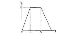
- the first process heats the spring steel material to a preset temperature, and after the first process, the spring steel material is set to the set temperature.
- set temperature is higher than 430 degreeC and 500 degrees C or less is set.
- the set temperature means the temperature of the surface of the spring steel material at the portion where the current flows.
- the set temperature is set higher than 430 ° C. and lower than 500 ° C. for the following reason. This is because the heat treatment time cannot be sufficiently shortened when the set temperature is 430 ° C. or lower. On the other hand, when the set temperature exceeds 500 ° C., the structure of the spring steel material is transformed, and the mechanical characteristics thereof change.
- the set temperature is set so that the time required for the first step and the second step is within 1 minute and the set time for the second step is 5 seconds or more. According to such a configuration, the difference between the time required for the molding process and the time required for the heat treatment process is reduced, and the spring can be manufactured efficiently.
- This energization heating apparatus includes a first electrode that can be electrically connected to one end of a coil spring, a first clamping mechanism that can clamp one end of the coil spring, and an electric terminal that is electrically connected to the other end of the coil spring.
- a second clamp mechanism having a connectable second electrode and capable of clamping the other end of the coil spring; and a power supply device for applying a voltage between the first electrode and the second electrode. Yes.
- At least one of the first clamp mechanism and the second clamp mechanism can move in the axial direction of the coil spring and can rotate around the axis of the coil spring with respect to the other clamp mechanism.
- the flowchart which shows the manufacturing method of the spring which concerns on an Example.
- the figure which shows typically the temperature profile between step S12 of FIG.
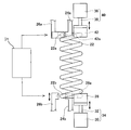
- the side view which shows typically the electricity heating apparatus which can be used for the process of step S12.
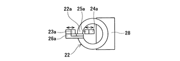
- the top view of the electric heating apparatus of FIG. The figure which shows the relationship between heat processing temperature and time when the amount of heat processing (residual stress and hardness after heat processing) becomes the same.
- a method for manufacturing the spring according to the embodiment will be described.
- a case of manufacturing a car suspension coil spring (hereinafter referred to as a suspension coil spring), which is a kind of spring, will be described as an example.
- the suspension coil spring is disposed between the vehicle body and the wheel, and generates a force that presses the wheel against the road surface.
- the suspension coil spring is manufactured by forming a spring steel material into a spiral shape.
- As the spring steel material a spring wire material having a constant cross-sectional area perpendicular to the axial direction can be used.
- the set temperature T 1 is set according to the time (0 to t 2 ) for performing the heat treatment in step S12.
- FIG. 5 shows a heat treatment condition in which the residual stress and hardness of the spring steel material (SUP12) after heat treatment are the same (that is, a condition in which the same amount of heat treatment is applied to the spring steel material).
- ⁇ and ⁇ indicate different values of residual stress and hardness after heat treatment, but between ⁇ and ⁇ indicate that the residual stress and hardness after heat treatment are the same value.
- the heat treatment temperature is increased, the treatment time is shortened.
- the heat treatment temperature (set temperature T 1 ) when it is desired to shorten the processing time, the heat treatment temperature (set temperature T 1 ) is increased, and when it is desired to increase the processing time, the heat treatment temperature (set temperature T 1 ) is decreased. Therefore, first, set the heat treatment time in step S12, by setting the set temperatures T 1 in accordance with the heat treatment time was the setting can be applied in heat treatment time set the heat treatment appropriate amount of spring steel . In addition, it is preferable to determine suitably the heat processing time of step S12 according to the time which the shaping
- the electric heating device includes a clamp mechanism (24 a, 26 a) that clamps the upper end 22 a of the spring steel material 22, a clamp mechanism (24 b, 26 b) that clamps the lower end 22 b of the spring steel material 22, A power supply device 50 is provided.
- the clamp mechanism (24a, 26a) includes clamp members 24a, 26a. As shown in FIG. 4, electrodes 25a and 23a are attached to the clamp members 24a and 26a, respectively. The electrodes 25a and 23a are formed with contact surfaces that follow the shape of the spring steel material 22. The electrodes 25 a and 23 a are connected to the power supply device 50.
- the clamp mechanism (24a, 26a) is rotatable around the winding axis of the spring steel material 22 (that is, the axis of the suspension coil spring). Thereby, even if the spring steel material 22 is deformed by energization heating, the deformation can be dealt with.
- the jig 28 and the clamp mechanism (24b, 26b) move upward, and then the lower end 22b of the spring steel material 22 is clamped by the clamp mechanism (24b, 26b).
- a voltage is applied by the power supply device 50 between the upper end and the lower end of the spring steel material 22 in this state, and the spring steel material 22 is energized. Thereby, the spring steel material 22 is heated.
- the clamp mechanism (24b, 26b) opens the lower end 22b of the spring steel material 22, and then the jig 28 and the clamp mechanism (24b, 26b) are retracted downward.
- a robot hand not shown
- the clamp mechanism (24a, 26a) opens the upper end 22a of the spring steel material 22, and then the robot hand conveys the spring steel material 22 outside the apparatus.
- step S16 When the heating of the spring steel material in step S16 is completed, the spring steel material is naturally cooled, and then paint is sprayed on the surface of the spring steel material (S18).
- paint for spraying the paint, for example, spray coating in which the paint is atomized and sprayed with high-pressure air can be used. Alternatively, the paint can be sprayed by electrostatic coating.
Abstract
Description
例えば、上述した実施例では、懸架用コイルばねを製造する例であったが、本願に係る技術は懸架用コイルばね以外のばねを製造する場合にも適用することができる。例えば、スタビライザ、トーションバー等の製造に用いることもできる。
また、ステップS12の熱処理を適切に行うために、非接触温度計(例えば、放射温度計、サーモグラフ)でばね鋼材の表面温度を測定し、その測定した表面温度に基づいてばね鋼材への電流量と時間を制御してもよい。これによって、ばね鋼材の温度が精度よく制御され、ばね鋼材に適切な量の熱処理を実施することができる。
また、上述した実施例は、ばね鋼材を冷間又は温間でばね形状に成形することで生じた加工歪みを除去する熱処理(焼鈍処理)に本願の通電加熱方法を適用した例であったが、本明細書に開示の技術はこのような例に限られない。例えば、ばね鋼材を熱間でばね形状に成形し、焼入れ後に行われる熱処理工程(焼戻し処理)に、本明細書に開示の通電加熱方法を適用することもできる。
Claims (4)
- ばねを製造する方法であって、
ばね鋼材をばね形状に成形する成形工程と、
成形工程によってばね鋼材に生じる加工歪みを除去する熱処理工程と、を有しており、
熱処理工程は、ばね鋼材に電流を流すことでばね鋼材を加熱する通電加熱によって行われると共に、ばね鋼材を予め設定された設定温度まで加熱する第1工程と、第1工程後に、ばね鋼材を設定温度で予め設定された設定時間だけ保持する第2工程を有しており、
前記設定温度が430℃より高く、かつ、500℃以下に設定されていることを特徴とするばねの製造方法。 - 第1工程と第2工程に要する時間が1分以内で、かつ、前記設定時間が5秒以上となるように、前記設定温度が設定されていることを特徴とする請求項1に記載のばねの製造方法。
- 熱処理工程では、ばね鋼材の温度を計測し、その計測した温度に基づいてばね鋼材に流す電流量と時間を制御することを特徴とする請求項1又は2に記載のばねの製造方法。
- コイルばねを通電加熱する装置であって、
コイルばねの一端に電気的に接続可能な第1の電極を備えると共に、該コイルばねの一端をクランプ可能な第1のクランプ機構と、
コイルばねの他端に電気的に接続可能な第2の電極を備えると共に、該コイルばねの他端をクランプ可能な第2のクランプ機構と、
第1の電極と第2の電極の間に電圧を印加する電源装置と、を有しており、
第1のクランプ機構と第2のクランプ機構の少なくとも一方が、他方のクランプ機構に対して、コイルばねの軸線方向に移動可能であると共にコイルばねの軸線周りに回転可能であることを特徴とする通電加熱装置。
Priority Applications (6)
| Application Number | Priority Date | Filing Date | Title |
|---|---|---|---|
| CN201180036389XA CN103025897A (zh) | 2010-07-26 | 2011-07-12 | 弹簧的制造方法和通电加热装置 |
| US13/812,138 US9623475B2 (en) | 2010-07-26 | 2011-07-12 | Method for producing spring |
| JP2012526411A JP5865246B2 (ja) | 2010-07-26 | 2011-07-12 | ばねの製造方法及び通電加熱装置 |
| BR112013001967A BR112013001967A2 (pt) | 2010-07-26 | 2011-07-12 | método para a produção de mola e dispositivo de aquecimento elétrico |
| DE112011102489T DE112011102489T5 (de) | 2010-07-26 | 2011-07-12 | Verfahren zur Herstellung einer Feder sowie elektrische Heizeinrichtung |
| US15/448,969 US20170175216A1 (en) | 2010-07-26 | 2017-03-03 | Electrical heating device |
Applications Claiming Priority (2)
| Application Number | Priority Date | Filing Date | Title |
|---|---|---|---|
| JP2010166806 | 2010-07-26 | ||
| JP2010-166806 | 2010-07-26 |
Related Child Applications (2)
| Application Number | Title | Priority Date | Filing Date |
|---|---|---|---|
| US13/812,138 A-371-Of-International US9623475B2 (en) | 2010-07-26 | 2011-07-12 | Method for producing spring |
| US15/448,969 Division US20170175216A1 (en) | 2010-07-26 | 2017-03-03 | Electrical heating device |
Publications (1)
| Publication Number | Publication Date |
|---|---|
| WO2012014672A1 true WO2012014672A1 (ja) | 2012-02-02 |
Family
ID=45529888
Family Applications (1)
| Application Number | Title | Priority Date | Filing Date |
|---|---|---|---|
| PCT/JP2011/065886 WO2012014672A1 (ja) | 2010-07-26 | 2011-07-12 | ばねの製造方法及び通電加熱装置 |
Country Status (6)
| Country | Link |
|---|---|
| US (2) | US9623475B2 (ja) |
| JP (1) | JP5865246B2 (ja) |
| CN (1) | CN103025897A (ja) |
| BR (1) | BR112013001967A2 (ja) |
| DE (1) | DE112011102489T5 (ja) |
| WO (1) | WO2012014672A1 (ja) |
Cited By (6)
| Publication number | Priority date | Publication date | Assignee | Title |
|---|---|---|---|---|
| WO2013099821A1 (ja) * | 2011-12-26 | 2013-07-04 | 中央発條株式会社 | ばねの製造方法及びばね |
| KR20150029018A (ko) * | 2012-07-06 | 2015-03-17 | 반즈 그룹 인크. | 고피로 아치형 스프링 |
| EP2551547A4 (en) * | 2010-03-23 | 2015-09-30 | Chuo Hatsujo Kk | METHOD FOR PRODUCING SPRING |
| KR20180022418A (ko) * | 2016-08-24 | 2018-03-06 | 울산대학교 산학협력단 | 코일 스프링 성형용 잔류응력 제어장치 |
| JP6975873B1 (ja) * | 2020-03-25 | 2021-12-01 | 日本発條株式会社 | アークスプリングの製造方法及び装置 |
| WO2023188536A1 (ja) * | 2022-03-30 | 2023-10-05 | 日本発條株式会社 | 加熱方法および加熱システム |
Families Citing this family (9)
| Publication number | Priority date | Publication date | Assignee | Title |
|---|---|---|---|---|
| JP2016191445A (ja) * | 2015-03-31 | 2016-11-10 | 日本発條株式会社 | コイルスプリング |
| CN105030499A (zh) * | 2015-08-11 | 2015-11-11 | 李秋华 | 一种神经内科用多功能按摩系统 |
| CN106498142A (zh) * | 2015-09-07 | 2017-03-15 | 南京工程学院 | 一种高强度变截面簧片制造中的应力喷丸方法 |
| CN106011434A (zh) * | 2016-08-03 | 2016-10-12 | 苏州市虎丘区浒墅关弹簧厂 | 一种抗变形弹簧的退火工艺 |
| CN107523679A (zh) * | 2017-08-31 | 2017-12-29 | 大连东非特钢制品有限公司 | 电极加热热处理方法 |
| CN108326192B (zh) * | 2017-12-08 | 2019-04-26 | 天津市曙光金属网有限公司 | 一种金属丝去应力矫直加工方法 |
| KR102065353B1 (ko) * | 2018-09-12 | 2020-01-13 | 대원강업주식회사 | 뜨임 및 핫세팅 통합 공정에 의한 자동차 현가장치 코일스프링 생산 방법 |
| CN112629725B (zh) * | 2020-12-04 | 2022-06-07 | 江苏徐工工程机械研究院有限公司 | 一种活塞杆喷涂层残余应力测试方法 |
| DE202023101010U1 (de) | 2023-03-03 | 2023-03-24 | Alcomex Beheer Bv | Fertigungsanlage zur Wärmebehandlung von warm- und kaltgeformten Federelementen |
Citations (5)
| Publication number | Priority date | Publication date | Assignee | Title |
|---|---|---|---|---|
| JPS5591946A (en) * | 1978-12-29 | 1980-07-11 | Jiro Morita | Coil spring annealing method |
| JPS6130246A (ja) * | 1984-07-19 | 1986-02-12 | Toshikazu Okuno | スプリングの加熱装置 |
| JPS6164812A (ja) * | 1984-09-04 | 1986-04-03 | Nhk Spring Co Ltd | 車両用鋼製部品の製造方法 |
| JPH01184234A (ja) * | 1988-01-18 | 1989-07-21 | Nippon Steel Corp | 高疲労強度コイルばねの製造方法 |
| JP2003105498A (ja) * | 2001-09-28 | 2003-04-09 | Togo Seisakusho Corp | 高強度ばねおよびその製造方法 |
Family Cites Families (27)
| Publication number | Priority date | Publication date | Assignee | Title |
|---|---|---|---|---|
| US2105105A (en) * | 1936-08-19 | 1938-01-11 | Nachman Spring Filled Corp | Machine for electrically heating springs |
| US2254525A (en) * | 1939-09-18 | 1941-09-02 | L A Young Spring & Wire Corp | Machine for manufacturing coil springs |
| US2666723A (en) * | 1951-12-19 | 1954-01-19 | Associated Spring Corp | Method of manufacturing helical coil compression springs |
| US3311733A (en) * | 1963-09-24 | 1967-03-28 | Illinois Coil Spring Co | Method and apparatus for precision heat treatment of coil springs |
| US3891823A (en) * | 1973-02-13 | 1975-06-24 | Kuhlman Corp | Methods for the manufacture of spring assemblies |
| US3935413A (en) * | 1974-05-30 | 1976-01-27 | Torin Corporation | Apparatus for stress relieving springs and the like |
| US3890687A (en) * | 1974-11-04 | 1975-06-24 | Joseph H Goldberg | Method for spring assembly |
| SE445228B (sv) * | 1984-10-15 | 1986-06-09 | Tekno Detaljer Lindstrom & Wae | Anordning for vermebehandling av skruvlindade fjedrar |
| CN1024812C (zh) * | 1992-07-06 | 1994-06-01 | 冶金工业部钢铁研究总院 | 提高冷加工线材延伸率的方法及装置 |
| CN1194187A (zh) * | 1997-03-24 | 1998-09-30 | 圣于尔班冶金工场 | 弯曲形螺旋弹簧的制造方法、如此获得的弹簧以及实施该方法的装置 |
| JPH1184234A (ja) | 1997-09-02 | 1999-03-26 | Konica Corp | 撮影レンズ |
| JP2000345238A (ja) * | 1999-03-31 | 2000-12-12 | Showa Corp | 自動車用懸架ばねの製造方法 |
| BR0011428A (pt) * | 1999-06-08 | 2002-03-26 | Nhk Spring Co Ltd | Mola altamente reforçada e processo para produzir a mesma |
| US6235131B1 (en) * | 1999-07-09 | 2001-05-22 | Mathew Warren Industries, Inc. | System for heat treating coiled springs |
| IT1313800B1 (it) * | 1999-10-19 | 2002-09-23 | Simplex Rapid Di Boschiero Cor | Metodo per variare in modo continuo e controllato,durante laproduzione di molle,la loro tensione iniziale e macchina realizzante |
| JP4558183B2 (ja) | 2000-12-14 | 2010-10-06 | 中央発條株式会社 | 弁ばねの製造方法 |
| US6713944B2 (en) * | 2002-01-02 | 2004-03-30 | Omron Corporation | Actuator and method of manufacturing a strain element |
| JP4010829B2 (ja) * | 2002-02-21 | 2007-11-21 | 中央発條株式会社 | コイルばねの製造方法及びその装置 |
| CA2517312C (en) * | 2003-02-27 | 2007-12-04 | University Of Washington | Design of ferromagnetic shape memory alloy composites and actuators incorporating such materials |
| US8006529B2 (en) * | 2003-09-12 | 2011-08-30 | Dreamwell, Ltd. | Methods for manufacturing coil springs |
| ITPN20040044A1 (it) * | 2004-06-15 | 2004-09-15 | Romeo Bordignon | Macchina perfezionata per produzione di molle a filo |
| JP2008248355A (ja) | 2007-03-30 | 2008-10-16 | Nikko Kinzoku Kk | 電子部品用チタン銅及びこれを用いた電子部品 |
| JP5001874B2 (ja) | 2008-02-22 | 2012-08-15 | 中央発條株式会社 | 高疲労強度及び高腐食疲労強度を有する冷間成形ばね、並びにばね鋼線材の製造方法 |
| CN201381348Y (zh) * | 2009-04-16 | 2010-01-13 | 江苏南汽常随汽车零部件有限公司 | 汽车稳定杆的电极夹紧定位装置 |
| US8308150B2 (en) * | 2009-06-17 | 2012-11-13 | Nhk Spring Co., Ltd. | Coil spring for vehicle suspension and method for manufacturing the same |
| US8506732B2 (en) * | 2009-08-07 | 2013-08-13 | Radyne Corporation | Heat treatment of helical springs or similarly shaped articles by electric resistance heating |
| JP5805371B2 (ja) * | 2010-03-23 | 2015-11-04 | 日本発條株式会社 | コイルばねの熱処理方法 |
-
2011
- 2011-07-12 WO PCT/JP2011/065886 patent/WO2012014672A1/ja active Application Filing
- 2011-07-12 DE DE112011102489T patent/DE112011102489T5/de not_active Ceased
- 2011-07-12 US US13/812,138 patent/US9623475B2/en not_active Expired - Fee Related
- 2011-07-12 BR BR112013001967A patent/BR112013001967A2/pt not_active IP Right Cessation
- 2011-07-12 CN CN201180036389XA patent/CN103025897A/zh active Pending
- 2011-07-12 JP JP2012526411A patent/JP5865246B2/ja active Active
-
2017
- 2017-03-03 US US15/448,969 patent/US20170175216A1/en not_active Abandoned
Patent Citations (5)
| Publication number | Priority date | Publication date | Assignee | Title |
|---|---|---|---|---|
| JPS5591946A (en) * | 1978-12-29 | 1980-07-11 | Jiro Morita | Coil spring annealing method |
| JPS6130246A (ja) * | 1984-07-19 | 1986-02-12 | Toshikazu Okuno | スプリングの加熱装置 |
| JPS6164812A (ja) * | 1984-09-04 | 1986-04-03 | Nhk Spring Co Ltd | 車両用鋼製部品の製造方法 |
| JPH01184234A (ja) * | 1988-01-18 | 1989-07-21 | Nippon Steel Corp | 高疲労強度コイルばねの製造方法 |
| JP2003105498A (ja) * | 2001-09-28 | 2003-04-09 | Togo Seisakusho Corp | 高強度ばねおよびその製造方法 |
Cited By (9)
| Publication number | Priority date | Publication date | Assignee | Title |
|---|---|---|---|---|
| EP2551547A4 (en) * | 2010-03-23 | 2015-09-30 | Chuo Hatsujo Kk | METHOD FOR PRODUCING SPRING |
| WO2013099821A1 (ja) * | 2011-12-26 | 2013-07-04 | 中央発條株式会社 | ばねの製造方法及びばね |
| KR20150029018A (ko) * | 2012-07-06 | 2015-03-17 | 반즈 그룹 인크. | 고피로 아치형 스프링 |
| JP2015523515A (ja) * | 2012-07-06 | 2015-08-13 | バーンズ グループ インコーポレーテッド | 高疲労性の弧状ばね |
| KR102011176B1 (ko) * | 2012-07-06 | 2019-08-14 | 반즈 그룹 인크. | 고피로 아치형 스프링 |
| KR20180022418A (ko) * | 2016-08-24 | 2018-03-06 | 울산대학교 산학협력단 | 코일 스프링 성형용 잔류응력 제어장치 |
| KR101879571B1 (ko) * | 2016-08-24 | 2018-07-19 | 울산대학교 산학협력단 | 코일 스프링 성형용 잔류응력 제어장치 |
| JP6975873B1 (ja) * | 2020-03-25 | 2021-12-01 | 日本発條株式会社 | アークスプリングの製造方法及び装置 |
| WO2023188536A1 (ja) * | 2022-03-30 | 2023-10-05 | 日本発條株式会社 | 加熱方法および加熱システム |
Also Published As
| Publication number | Publication date |
|---|---|
| BR112013001967A2 (pt) | 2019-09-24 |
| US9623475B2 (en) | 2017-04-18 |
| US20170175216A1 (en) | 2017-06-22 |
| JP5865246B2 (ja) | 2016-02-17 |
| US20130119045A1 (en) | 2013-05-16 |
| DE112011102489T5 (de) | 2013-07-25 |
| CN103025897A (zh) | 2013-04-03 |
| JPWO2012014672A1 (ja) | 2013-09-12 |
Similar Documents
| Publication | Publication Date | Title |
|---|---|---|
| JP5865246B2 (ja) | ばねの製造方法及び通電加熱装置 | |
| WO2013099821A1 (ja) | ばねの製造方法及びばね | |
| JP5511451B2 (ja) | 自動車用スタビライザの製造方法 | |
| WO2014034375A1 (ja) | スタビライザの製造方法および加熱装置 | |
| US8460483B2 (en) | Method for heat treatment of coiled spring | |
| US8506732B2 (en) | Heat treatment of helical springs or similarly shaped articles by electric resistance heating | |
| JP5550405B2 (ja) | ばねの製造方法 | |
| US20130092675A1 (en) | Method and apparatus for electrically heating spring | |
| WO2004085685A1 (ja) | 高強度ばねの製造方法 | |
| JP3634418B2 (ja) | コイルばねの製造方法及び高靭性・高抗張力コイルばね | |
| JP6234380B2 (ja) | 横方向ストラット及び横方向ストラットを形成する方法 | |
| JPH07217683A (ja) | ばね部材の内部応力分布を最適化する方法 | |
| KR102122809B1 (ko) | 자동차 현가장치 코일스프링 생산 방법 | |
| JP3555814B2 (ja) | コイルばね製造方法 | |
| JP6061685B2 (ja) | ラックの製造方法 | |
| WO2024075314A1 (ja) | コイルばねの製造方法 | |
| KR20100104770A (ko) | 스프링 제조방법 | |
| JP4018331B2 (ja) | ダブルテーパ鋼線と、その連続熱処理方法および装置 | |
| JPS6359775B2 (ja) | ||
| KR102181670B1 (ko) | 자동차 현가장치용 코일스프링 생산 방법 | |
| JP6259198B2 (ja) | 板ばねの製造方法 | |
| JP2001004508A (ja) | 加工熱処理再現試験装置 |
Legal Events
| Date | Code | Title | Description |
|---|---|---|---|
| WWE | Wipo information: entry into national phase |
Ref document number: 201180036389.X Country of ref document: CN |
|
| 121 | Ep: the epo has been informed by wipo that ep was designated in this application |
Ref document number: 11812264 Country of ref document: EP Kind code of ref document: A1 |
|
| WWE | Wipo information: entry into national phase |
Ref document number: 2012526411 Country of ref document: JP |
|
| WWE | Wipo information: entry into national phase |
Ref document number: 13812138 Country of ref document: US |
|
| WWE | Wipo information: entry into national phase |
Ref document number: 112011102489 Country of ref document: DE Ref document number: 1120111024894 Country of ref document: DE |
|
| 122 | Ep: pct application non-entry in european phase |
Ref document number: 11812264 Country of ref document: EP Kind code of ref document: A1 |
|
| REG | Reference to national code |
Ref country code: BR Ref legal event code: B01A Ref document number: 112013001967 Country of ref document: BR |
|
| ENP | Entry into the national phase |
Ref document number: 112013001967 Country of ref document: BR Kind code of ref document: A2 Effective date: 20130125 |