WO2012014647A1 - 基板内蔵用キャパシタ、これを備えたキャパシタ内蔵基板、及び基板内蔵用キャパシタの製造方法 - Google Patents
基板内蔵用キャパシタ、これを備えたキャパシタ内蔵基板、及び基板内蔵用キャパシタの製造方法 Download PDFInfo
- Publication number
- WO2012014647A1 WO2012014647A1 PCT/JP2011/065544 JP2011065544W WO2012014647A1 WO 2012014647 A1 WO2012014647 A1 WO 2012014647A1 JP 2011065544 W JP2011065544 W JP 2011065544W WO 2012014647 A1 WO2012014647 A1 WO 2012014647A1
- Authority
- WO
- WIPO (PCT)
- Prior art keywords
- electrode
- dielectric layer
- capacitor
- substrate
- layer
- Prior art date
- Legal status (The legal status is an assumption and is not a legal conclusion. Google has not performed a legal analysis and makes no representation as to the accuracy of the status listed.)
- Ceased
Links
Images



Classifications
-
- H—ELECTRICITY
- H01—ELECTRIC ELEMENTS
- H01G—CAPACITORS; CAPACITORS, RECTIFIERS, DETECTORS, SWITCHING DEVICES, LIGHT-SENSITIVE OR TEMPERATURE-SENSITIVE DEVICES OF THE ELECTROLYTIC TYPE
- H01G4/00—Fixed capacitors; Processes of their manufacture
- H01G4/002—Details
- H01G4/018—Dielectrics
- H01G4/06—Solid dielectrics
- H01G4/08—Inorganic dielectrics
- H01G4/12—Ceramic dielectrics
-
- H—ELECTRICITY
- H01—ELECTRIC ELEMENTS
- H01G—CAPACITORS; CAPACITORS, RECTIFIERS, DETECTORS, SWITCHING DEVICES, LIGHT-SENSITIVE OR TEMPERATURE-SENSITIVE DEVICES OF THE ELECTROLYTIC TYPE
- H01G4/00—Fixed capacitors; Processes of their manufacture
- H01G4/002—Details
- H01G4/018—Dielectrics
- H01G4/06—Solid dielectrics
- H01G4/14—Organic dielectrics
- H01G4/18—Organic dielectrics of synthetic material, e.g. derivatives of cellulose
-
- H—ELECTRICITY
- H01—ELECTRIC ELEMENTS
- H01G—CAPACITORS; CAPACITORS, RECTIFIERS, DETECTORS, SWITCHING DEVICES, LIGHT-SENSITIVE OR TEMPERATURE-SENSITIVE DEVICES OF THE ELECTROLYTIC TYPE
- H01G4/00—Fixed capacitors; Processes of their manufacture
- H01G4/33—Thin- or thick-film capacitors (thin- or thick-film circuits; capacitors without a potential-jump or surface barrier specially adapted for integrated circuits, details thereof, multistep manufacturing processes therefor)
-
- H—ELECTRICITY
- H05—ELECTRIC TECHNIQUES NOT OTHERWISE PROVIDED FOR
- H05K—PRINTED CIRCUITS; CASINGS OR CONSTRUCTIONAL DETAILS OF ELECTRIC APPARATUS; MANUFACTURE OF ASSEMBLAGES OF ELECTRICAL COMPONENTS
- H05K1/00—Printed circuits
- H05K1/16—Printed circuits incorporating printed electric components, e.g. printed resistors, capacitors or inductors
- H05K1/162—Printed circuits incorporating printed electric components, e.g. printed resistors, capacitors or inductors incorporating printed capacitors
-
- H—ELECTRICITY
- H05—ELECTRIC TECHNIQUES NOT OTHERWISE PROVIDED FOR
- H05K—PRINTED CIRCUITS; CASINGS OR CONSTRUCTIONAL DETAILS OF ELECTRIC APPARATUS; MANUFACTURE OF ASSEMBLAGES OF ELECTRICAL COMPONENTS
- H05K1/00—Printed circuits
- H05K1/02—Details
- H05K1/0213—Electrical arrangements not otherwise provided for
- H05K1/0216—Reduction of cross-talk, noise or electromagnetic interference
- H05K1/023—Reduction of cross-talk, noise or electromagnetic interference using auxiliary mounted passive components or auxiliary substances
- H05K1/0231—Capacitors or dielectric substances
-
- Y—GENERAL TAGGING OF NEW TECHNOLOGICAL DEVELOPMENTS; GENERAL TAGGING OF CROSS-SECTIONAL TECHNOLOGIES SPANNING OVER SEVERAL SECTIONS OF THE IPC; TECHNICAL SUBJECTS COVERED BY FORMER USPC CROSS-REFERENCE ART COLLECTIONS [XRACs] AND DIGESTS
- Y10—TECHNICAL SUBJECTS COVERED BY FORMER USPC
- Y10T—TECHNICAL SUBJECTS COVERED BY FORMER US CLASSIFICATION
- Y10T29/00—Metal working
- Y10T29/43—Electric condenser making
- Y10T29/435—Solid dielectric type
Definitions
- the present invention relates to a substrate built-in capacitor built into a substrate, a capacitor built-in substrate provided with the same, and a method of manufacturing the above-mentioned substrate built-in capacitor.
- a capacitor (so-called capacitor) to be mounted on a printed wiring board inside the board without mounting it on the surface of the board.
- a substrate built-in capacitor built in a substrate has a structure in which metal-insulator-metal are stacked in this order, that is, a structure in which an insulator layer is sandwiched between electrode layers (for example, Patent Documents). 1).
- the electrodes constituting the capacitor by sandwiching the dielectric layer are respectively connected to the wiring (circuit) through one via. ing.
- the lower electrode provided on the lower surface of the dielectric layer is electrically connected to the wiring provided below the lower electrode via a via.
- the upper electrode provided on the upper surface of the dielectric layer is electrically connected to a wiring provided above the upper electrode through a via.
- a substrate 109 shown in FIG. 12 includes a capacitor 101 incorporated therein, and the capacitor 101 includes a first electrode 110, a dielectric layer 130 provided on the first electrode 110, and a dielectric layer 130.
- a first electrode 110 and a second electrode 120 facing each other are provided.
- a wiring 171 electrically connected to the first electrode 110 and a wiring 172 electrically connected to the second electrode 120 are formed on one surface of the substrate 109.
- the second electrode 120 constituting the upper electrode is connected to the wiring 172 through one via 162.
- the first electrode 110 constituting the lower electrode is connected to the wiring 173 provided on the surface opposite to the wiring 171 through the via 163, and the wiring 173 is connected to the wiring 171 through the via 161.
- the first electrode 110 is connected to the wiring 171.
- the capacitor 101 shown in FIG. 12 is built in the substrate 109, in order to connect the wiring 171 provided on one surface of the substrate 109 to the first electrode 110, one surface of the substrate 109 is connected to the other surface.
- the via 161 reaching the first electrode 110 is formed, and the via 163 extending from the other surface to the first electrode 110 is formed.
- the conductive path from one surface of the substrate 109 to the first electrode 110 is long.
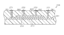
- FIG. 1 As a capacitor that can connect the wiring provided on one surface of the substrate to the first electrode and the second electrode without forming a via from one surface of the substrate to the other surface, for example, FIG. The following can be considered.
- a capacitor 201 built in the substrate 209 shown in FIG. 13 includes a first electrode 210 having a size larger than that of the dielectric layer 230 and the second electrode 220, and the second electrode 220 constituting the upper electrode has one via 262.
- the first electrode 210 constituting the lower electrode is also connected to the wiring 271 through one via 261.
- the first electrode 210 and the second electrode 220 It becomes difficult to properly form the vias 261 and 262 to be connected.
- the vias connected to the first electrode 210 and the second electrode 220 are not limited to the lengths of the vias 261 and 262, and the materials forming the first electrode 210 and the second electrode 220 are different from each other. It becomes difficult to form 261,262 appropriately.
- the vias connected to the first electrode and the second electrode constituting the substrate built-in capacitor cannot be properly formed, the vias formed on the substrate cannot be connected well to the first electrode and the second electrode. There is a problem.
- An object of the present invention is to provide a substrate built-in capacitor, a capacitor built-in substrate, and a method for manufacturing the substrate built-in capacitor that can satisfactorily connect the first electrode and the second electrode.
- a substrate built-in capacitor according to the present invention includes a first electrode extending in a predetermined direction, a dielectric layer provided in a partial region of the first electrode, and a dielectric layer provided on the dielectric layer.
- a portion of the electrode layer is provided at an end of the dielectric layer at a distance from the second electrode in the predetermined direction, and is opposed to the first electrode through the dielectric layer. It is characterized by.
- a method of manufacturing a capacitor for incorporating a substrate according to the present invention includes a dielectric layer forming step of forming a dielectric layer on a first electrode layer, and the dielectric on the dielectric layer.
- the via formed on the substrate, the first electrode, and the second electrode are connected to each other. It is possible to connect well, and a conductive path from one surface of the substrate to the first electrode can be shortened.
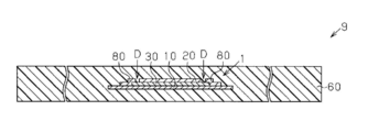
- FIG. 1 is a cross-sectional view showing a schematic configuration of a substrate built-in capacitor according to an embodiment of the present invention and a capacitor built-in substrate in which the capacitor is built.
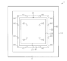
- the top view which shows the capacitor for a board
- substrate built-in which concerns on the 2nd modification of this invention Sectional drawing which shows schematic structure of the capacitor for a board
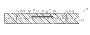
- a capacitor 1 according to the present invention is a substrate built-in capacitor built in a substrate 9.
- An arrow X in the figure indicates a surface direction X that is a predetermined linear direction.
- An arrow Y in the drawing indicates a thickness direction Y that is a direction perpendicular to the surface direction X.
- the capacitor 1 includes a first electrode 10, a dielectric layer 30 provided on the first electrode 10, and a second electrode provided on the dielectric layer 30 and facing the first electrode 10 through the dielectric layer 30. 20 and an electrode layer 80 provided on the first electrode 10 and the dielectric layer 30 and connected to the first electrode 10.
- FIG. 2 which is a plan view of the capacitor 1, in the present embodiment, the first electrode 10, the second electrode 20, and the dielectric layer 30 have a rectangular shape.
- a portion indicated by a broken line H1 indicates a portion to which the via 61 shown in FIG. 1 is connected.
- a portion indicated by a broken line H2 indicates a portion to which the via 62 shown in FIG. 1 is connected.
- the first electrode 10 made of a conductive material such as metal is formed of a metal foil made of a metal such as copper, nickel, aluminum, or platinum, or a metal foil made of an alloy containing two or more of these metals. .
- the thin flat plate-like first electrode 10 has a surface 11 on which the dielectric layer 30 is provided and a surface 12 provided on the opposite side of the surface 11.
- the second electrode 20 made of a conductive material such as metal is formed of a metal film made of a metal such as copper, nickel, aluminum, or platinum, or a metal film made of an alloy containing two or more of these metals. .
- the thin film-like second electrode 20 has a surface 21 to which the via 62 is connected, and is formed so as to sandwich the dielectric layer 30 together with the first electrode 10 in the thickness direction Y.
- the second electrode 20 has a smaller dimension in the plane direction X than the first electrode 10 and the dielectric layer 30.
- the second electrode 20 extending in the plane direction X covers the upper portion of the dielectric layer 30 as an upper electrode in FIG.
- the dielectric layer 30 formed of a dielectric is formed of, for example, an oxide ceramic. Specifically, for example, metal oxides such as barium titanate, lithium niobate, lithium borate, lead zirconate titanate, strontium titanate, lead lanthanum zirconate titanate, lithium tantalate, zinc oxide, tantalum oxide, etc. Thus, the dielectric layer 30 is formed.
- the dielectric layer 30 may contain an additive for improving the dielectric characteristics in addition to the above metal oxide.
- the dielectric layer 30 protrudes in the surface direction X from both ends of the second electrode 20.
- the dielectric layer 30 provided on the surface 11 of the first electrode 10 has a smaller dimension than the first electrode 10 in the surface direction X. That is, the dielectric layer 30 is provided in a partial region of the first electrode 10. For this reason, the first electrode 10 protrudes in the surface direction X from both ends of the dielectric layer 30.
- the electrode layer 80 made of a conductive material such as a metal is formed of a metal film such as a copper film, and is formed of the same material as the second electrode 20.
- the thin film electrode layer 80 has a surface 81 to which the via 61 is connected.
- the electrode layer 80 is formed so as to sandwich both end portions of the dielectric layer 30 together with the first electrode 10 in the thickness direction Y, and is formed so as to straddle the first electrode 10 and the dielectric layer 30. That is, the electrode layer 80 is provided on the first electrode 10 around the dielectric layer 30, a part of the electrode layer 80 is provided at the end of the dielectric layer 30 in the plane direction X, and a part of the electrode layer 80 is provided. Faces the first electrode 10 with the dielectric layer 30 in between.
- the electrode layer 80 thus provided covers both end faces of the dielectric layer 30 in the plane direction X, and the end of the electrode layer 80 in the plane direction X is connected to the first electrode 10.
- the electrode layer 80 is provided at a distance from the second electrode 20 in the plane direction X.
- a rectangular frame-shaped separation groove D is provided between the second electrode 20 and the electrode layer 80.
- the separation groove D provided in a portion excluding the peripheral edge of the dielectric layer 30 includes end surfaces of the second electrode 20 and the electrode layer 80 in the surface direction X where the second electrode 20 and the electrode layer 80 face each other, and the dielectric layer. And a part of the surface of the dielectric layer 30 and having the surface of the dielectric layer 30 as a bottom surface.
- a part of the electrode layer 80 is provided at the end of the dielectric layer 30 in the plane direction X, and the part of the electrode layer 80 and the first electrode 10 face each other with the dielectric layer 30 in between.
- a separation groove D that electrically separates the first electrode 10 and the second electrode 20 is formed between the electrode layer 80 and the second electrode 20 with the portion excluding the periphery of the dielectric layer 30 as a bottom surface. ing.
- the surface 21 of the second electrode 20 and the surface 81 of the electrode layer 80 are located on the same plane across the separation groove D.
- the substrate 9 is a capacitor built-in substrate in which the capacitor 1 having the above-described configuration is built.
- the substrate 9 includes a capacitor 1 and an insulating substrate 60 in which the capacitor 1 is built.
- a via 61 electrically connected to the first electrode 10 is formed, and the second electrode 20 is formed.
- a via 62 electrically connected to is formed.
- the via 61 is electrically connected to the first electrode 10 by being connected to the electrode layer 80.
- a wiring 71 electrically connected to the first electrode 10 and a wiring 72 connected to the second electrode 20 are formed on the surface of the insulating substrate 60.
- the wirings 71 and 72 are provided on one surface of the substrate 9.
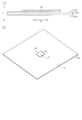
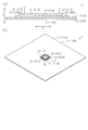
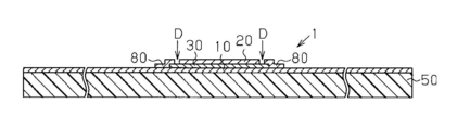
- FIGS. 3 (a), 4 (a), and 6 (a) are views along the alternate long and short dash line in FIGS. 3 (b), 4 (b), and 6 (b), respectively. It is sectional drawing.
- a first electrode layer 10A having a predetermined thickness that is easy to handle and hardly deforms in an annealing process described later is prepared.
- 10 A of 1st electrode layers are metal foil, Comprising: It is preferable that it is copper foil with high electroconductivity and easy acquisition.
- a dielectric layer 30 is formed on a part of the surface 11A of the first electrode layer 10A. That is, the dielectric layer 30 is formed on the first electrode layer 10A (dielectric layer forming step).
- the dielectric layer 30 is formed by a powder spray coating method in which a powdery dielectric is sprayed.
- a powder spray coating method for example, an aerosol deposition method or a powder jet deposition method can be used.
- a powder jet deposition method In order to easily form the dielectric layer 30 in a room temperature and atmospheric pressure environment, it is preferable to use a powder jet deposition method.
- the dielectric layer 30 is annealed (annealing step).
- the annealing process is performed by, for example, laser irradiation to the dielectric layer 30, microwave heating, heating in an annealing furnace, or the like.
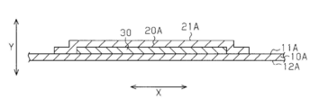
- a second electrode layer 20A that covers the dielectric layer 30 and is connected to the first electrode layer 10A is formed on the dielectric layer 30 (electrode).
- the second electrode layer 20A is provided on the surface of the dielectric layer 30.
- the second electrode layer 20A has a size larger than that of the dielectric layer 30 in the surface direction X continuous with the surface 11A of the first electrode layer 10A.
- end portions of the second electrode layer 20 ⁇ / b> A in the plane direction X cover both end surfaces of the dielectric layer 30 and are provided on the surface of the first electrode layer 10 ⁇ / b> A around the dielectric layer 30.
- the second electrode layer 20A is preferably formed of the same material (that is, copper) as the first electrode layer 10A, but may be formed of a material different from that of the first electrode layer 10A.
- the second electrode layer 20A which is a metal film, is formed by, for example, sputtering, vapor deposition, conductive paste printing, plating, or a film forming method combining these.
- a film forming method in the electrode layer forming step it is preferable to adopt a method having high adhesion at the interface between the first electrode layer 10A and the dielectric layer 30 and the second electrode layer 20A.
- the first electrode layer 10A is thinned (thinning step). That is, the dimension of the first electrode layer 10A in the thickness direction Y is uniformly reduced in the plane direction X.
- the thinning process is an etching process in which the first electrode layer 10A is thinned by etching.
- Etching is chemical polishing using a chemical reaction that dissolves metal.
- dry etching using an etching gas or wet etching using an etching solution can be used as the etching in the etching step.
- the second electrode layer 20 ⁇ / b> A is provided with a separation groove D that is a portion excluding the periphery of the dielectric layer 30 and has the surface of the dielectric layer 30 as a bottom surface.
- a separation groove D is formed in the second electrode layer 20A to electrically separate a portion facing the first electrode layer 10A via the dielectric layer 30 and a portion connected to the first electrode layer 10A.
- the separation groove D By forming the separation groove D, the first electrode 10 and the second electrode 20 which are not electrically connected are formed. By separating the second electrode layer 20A in this way, the portion of the second electrode layer 20A that faces the first electrode layer 10A via the dielectric layer 30 becomes the second electrode 20, and the first electrode layer 10A. Becomes the first electrode 10. Further, the portion of the second electrode layer 20A that is connected to the first electrode layer 10A is the electrode layer 80.
- the separation groove forming step is an electrode forming step in which the first electrode 10 and the second electrode 20 are formed by forming the separation groove D.
- the first electrode layer 10 ⁇ / b> A constitutes the first electrode 10
- the second electrode layer 20 ⁇ / b> A constitutes the second electrode 20 and the electrode layer 80.
- the surface 11A of the first electrode layer 10A constitutes the surface 11 of the first electrode 10
- the surface 12A of the first electrode layer 10A constitutes the surface 12 of the first electrode 10.
- the surface 21A of the second electrode layer 20A constitutes the surfaces 21 and 81 of the second electrode 20 and the electrode layer 80.
- the method for manufacturing the capacitor 1 includes a dielectric layer forming step, an annealing step, an electrode layer forming step, a thinning step (etching step), and a separation groove forming step. Through these steps, the capacitor 1 is manufactured.
- the insulator 50 includes a core material and a pair of prepregs that sandwich the core material.
- the capacitor 1 is pressure-bonded to the semi-cured prepreg by heating and pressurizing the insulator 50.
- the insulator 50 may be prepared in advance, and the capacitor 1 may be laminated on the cured prepreg via an adhesive layer (not shown).
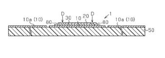
- the first electrode 10 is etched to form the internal wiring 10a (internal wiring forming step). That is, the first electrode 10 provided in the capacitor 1 constitutes an internal wiring 10 a provided in the substrate 9.
- the internal wiring 10 a may be a wiring that is not connected to the capacitor 1 or may be a wiring that is connected to the first electrode 10.
- another insulator 50 is stacked on the insulator 50 provided with the capacitor 1 by heating and pressing (insulator stacking layer step).
- insulator stacking layer step By performing the insulator stacking step, as shown in FIG. 9, an insulating substrate 60 is formed by the stacked insulators 50, and the substrate 9 in which the capacitor 1 is built is obtained.
- the method for manufacturing the substrate 9 includes the capacitor lamination process, the internal wiring formation process, the insulator lamination process, the via formation process, and the wiring formation process. Through these steps, the substrate 9 shown in FIG. 1 is manufactured.
- the capacitor 1 includes a first electrode 10, a dielectric layer 30 provided in a partial region of the first electrode 10, and a second electrode 20 that faces the first electrode 10 with the dielectric layer 30 interposed therebetween. And an electrode layer 80 provided on the first electrode 10 around the dielectric layer 30 and connected to the first electrode 10. A part of the electrode layer 80 is provided at the end of the dielectric layer 30 at a distance from the second electrode 20 in the plane direction X, and faces the first electrode 10 through the dielectric layer 30. ing.
- the capacitor 1 having such a configuration is built in the substrate 9, in order to connect the wirings 71 and 72 provided on one surface of the substrate 9 to the first electrode 10 and the second electrode 20, Vias 61 and 62 extending from one surface of the electrode layer 80 to the surface of the electrode layer 80 and the surface of the second electrode 20 are formed in the substrate 9. Then, by connecting the via 61 to the electrode layer 80, the wiring 71 provided on one surface of the substrate 9 and the first electrode 10 are connected, and the via 62 is directly connected to the second electrode 20. Accordingly, the wiring 72 provided on one surface of the substrate 9 and the second electrode 20 are connected.
- the capacitor 1 is built in the substrate 9, and the wirings 71 and 72 provided on one surface of the substrate 9 through the vias 61 and 62 formed in the substrate 9 are connected to the first electrode 10 and the second electrode 20.
- the vias 61 and 62 connected to the first electrode 10 and the second electrode 20 can be easily formed as compared with the case where the lengths of the vias 61 and 62 are different.
- the vias 61 and 62 and the first electrode 10 and the second electrode 20 are connected.
- the electrode 20 can be connected satisfactorily.
- the via 61 extending from the one surface of the substrate 9 to the surface of the electrode layer 80 is formed. Become. For this reason, compared with a configuration in which a via from one surface of the substrate 9 to the other surface is formed and a via from the other surface to the first electrode 10 is further formed, The conductive path leading to one electrode 10 can be shortened. Therefore, the vias 61 and 62 have the shortest distance between the surface of the substrate 9 on which the wirings 71 and 72 are provided and the capacitor 1, respectively. As a result, the inductance generated in the substrate 9 is reduced, and the impedance characteristics of the substrate 9 in the high frequency region are improved.
- the capacitor 1 having the above configuration is built in the substrate 9, there is no need to form a via whose bottom surface is the surface of the first electrode 10, and the surface of the electrode layer 80 and the second electrode 20.
- the vias 61 and 62 having the front surface as the bottom surface may be formed. For this reason, it is not necessary to ensure the thickness of the first electrode 10 in preparation for the formation of the vias 61 and 62, and it is possible to prevent the thickness of the first electrode 10 from increasing. Therefore, the capacitor 1 can be thinned.
- a separation groove D for electrically separating the first electrode 10 and the second electrode 20 is provided between the electrode layer 80 and the second electrode 20 with the portion excluding the periphery of the dielectric layer 30 as a bottom surface. It has been. For this reason, since the edge part of the dielectric material layer 30 is pinched
- the thin substrate 9 can be used as a component built in an electronic device (not shown).
- the surface 81 of the electrode layer 80 may not be completely located on the same plane as the surface 21 of the second electrode 20.
- the manufacturing method of the capacitor 1 includes a dielectric layer forming step for forming the dielectric layer 30, and an electrode layer formation for covering the dielectric layer 30 and forming the second electrode layer 20A connected to the first electrode layer 10A.
- the process includes a separation groove forming step of forming a separation groove D for electrically separating a portion facing the first electrode layer 10A and a portion connected to the first electrode layer 10A in the second electrode layer 20A.
- the separation electrode D is formed in the second electrode layer 20A that covers the dielectric layer 30 and is connected to the first electrode layer 10A, whereby the first electrode layer 10A becomes the first electrode 10, A portion of the second electrode layer 20 ⁇ / b> A that faces the first electrode layer 10 ⁇ / b> A through the dielectric layer 30 becomes the second electrode 20.
- the portion of the second electrode layer 20A to which the first electrode layer 10A is connected is provided in a partial region of the first electrode 10 and the electrode layer 80 provided at a distance from the second electrode 20 Become.
- the electrode layer 80 formed through the separation groove forming step is a part of the second electrode layer 20A before the separation groove forming step, and the electrode layer 80 is connected to the second electrode 20. It is provided similarly. Accordingly, a part of the electrode layer 80 connected to the first electrode 10 is provided at the end of the dielectric layer 30 with a space from the second electrode 20, and the first electrode is interposed via the dielectric layer 30. 10 to face the structure. For this reason, the effects according to the above (1) to (3) and (5) can be obtained.
- the separation groove D is formed in a portion excluding the peripheral edge of the dielectric layer 30 and a part of the dielectric layer 30 is a bottom surface. Therefore, the end portion of the dielectric layer 30 is sandwiched between a part of the electrode layer 80 and the first electrode 10. For this reason, the effect according to said (4) can be acquired.
- the method for manufacturing the capacitor 1 includes a thinning step for thinning the first electrode layer 10A after the dielectric layer forming step. This facilitates handling of the first electrode layer 10A until the dielectric layer 30 is formed, including when the dielectric layer 30 is formed. Further, since the first electrode layer 10A is thinned in the thinning step, the capacitor 1 can be thinned (so-called low profile).
- the method for manufacturing the capacitor 1 includes an annealing step of annealing the dielectric layer 30 after the dielectric layer forming step. For this reason, the ferroelectric characteristics of the dielectric layer 30 can be improved. If the thinning process is performed after the annealing process, the oxide film formed on the first electrode layer 10A due to the annealing process can be removed in the thinning process. As a result, it is possible to increase the maximum heating temperature in the annealing process that has been set low in order to suppress the formation of the oxide film. If the thinning process is performed after the annealing process, the thickness of the first electrode layer 10A can be ensured in the annealing process. As a result, it is possible to reduce the height of the capacitor 1 while suppressing the deformation of the first electrode layer 10A due to the annealing treatment.
- the dielectric layer 30 is formed by a powder spray coating method. For this reason, the dielectric layer 30 can be formed at room temperature by an aerosol deposition method, a powder jet deposition method, or the like. As a result, a metal having a low melting point can be used as the first electrode layer 10A serving as a base.
- the thinning process is an etching process in which the first electrode layer 10A is thinned by etching. For this reason, the first electrode layer 10A can be thinned to a desired thickness by chemical polishing.
- the method for manufacturing the substrate 9 includes an internal wiring forming step of forming the internal wiring 10 a by etching the first electrode 10. Therefore, the first electrode 10 provided in the capacitor 1 can be used for the internal wiring 10 a provided in the substrate 9.
- the separation groove D may not be formed in the second electrode layer 20A. That is, the manufacturing process of the capacitor 1 may be included in the manufacturing process of the substrate 9. The manufacturing process of the capacitor 1 and the substrate 9 in this case will be described below.
- the first electrode layer 10A obtained through the dielectric layer forming step, the annealing step, the electrode layer forming step, and the thinning step is laminated on the surface of the insulator 50 composed of the core material and the prepreg (electrode layer lamination). Process).
- the first electrode layer 10A is pressure-bonded to the semi-cured prepreg by heating and pressurizing the insulator 50.
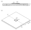
- the electrode layer laminating step As shown in FIGS. 10A and 10B, the insulator 50 provided with the exposed first electrode layer 10A is obtained.
- Fig.10 (a) is an arrow sectional drawing along the dashed-dotted line in FIG.10 (b).
- An adhesive layer (not shown) may be used in the same manner as the capacitor stacking step.
- a separation groove D is formed in the second electrode layer 20A provided in the insulator 50 (separation groove forming step).
- a substrate 9 shown in FIG. 9 is obtained by performing an internal wiring formation step and an insulator lamination step. And the board
- a separation groove forming step that is an electrode forming step is performed. Since the capacitance of the capacitor 1 depends on the area of the portion where the first electrode 10 and the second electrode 20 face each other, the formation position of the separation groove D is related to the capacitance of the capacitor 1. Therefore, by performing the separation groove forming step after the electrode layer stacking step, the capacitor 1 having a desired capacitance can be obtained when the substrate 9 is manufactured.
- the first electrode 10 provided in the capacitor 1 may not be used for the internal wiring 10 a provided in the substrate 9. That is, for example, as shown in FIG. 11, the first electrode 10 having a smaller dimension in the surface direction X than the first electrode 10 in the above embodiment may be used.
- the capacitor 1 is laminated on the surface of the insulator 50 in the same manner as the capacitor lamination step, and the insulator lamination step, via formation step, and wiring formation step are performed without going through the internal wiring formation step. After that, as shown in FIG. 11, the substrate 9 without the internal wiring 10a is manufactured.
- a plurality of dielectric layers 30 may be formed on one first electrode layer 10A.
- the first electrode layer 10A is cut in accordance with the shape of the dielectric layer 30, thereby manufacturing the plurality of capacitors 1 from one first electrode layer 10A. Also good.
- the second electrode 20 may be formed of a metal foil made of a metal such as copper, nickel, aluminum, or platinum, or a metal foil made of an alloy containing two or more of these metals.
- the second electrode layer 20A may be made of a metal foil.
- the second metal layer 20A is bonded to the first electrode layer 10A and the dielectric layer 30 in the electrode layer forming step, so that the second electrode layer 20A Electrode layer 20A is formed.
- the metal foil constituting the first electrode layer 10A may be plated. Moreover, when the 2nd electrode layer 20A is comprised with metal foil as mentioned above, plating may be given to this metal foil.
- the dielectric layer 30 may be formed by a method other than the powder spray coating method.
- the dielectric layer 30 may be formed by sputtering, vapor deposition, sol-gel method, or the like.
- the annealing step may be omitted.
- the first electrode layer 10A may be thinned by a method other than etching. That is, the method for thinning the first electrode layer 10A is not limited to chemical polishing.
- the first electrode layer 10A may be thinned by mechanical polishing or chemical mechanical polishing.
- D Separation groove
- X Plane direction
- Y Thickness direction
- 10 ... First electrode, 10a Internal wiring, 11, 12 ... Plane, 10A ... First electrode Layer, 11A, 12A ... surface, 20 ... second electrode, 21 ... surface, 21A ... surface, 20A ... second electrode layer, 21A ... surface, 30 ... dielectric layer, 50 ... insulator, 60 ... insulating substrate, 61 62 ... via, 71,72 ... wiring, 80 ... electrode layer, 81 ... surface.
Landscapes
- Engineering & Computer Science (AREA)
- Power Engineering (AREA)
- Microelectronics & Electronic Packaging (AREA)
- Manufacturing & Machinery (AREA)
- Chemical & Material Sciences (AREA)
- Ceramic Engineering (AREA)
- Inorganic Chemistry (AREA)
- Ceramic Capacitors (AREA)
- Fixed Capacitors And Capacitor Manufacturing Machines (AREA)
- Parts Printed On Printed Circuit Boards (AREA)
Abstract
Description
図12に示す基板109は、その内部に内蔵されたキャパシタ101を備え、キャパシタ101は、第1電極110と、第1電極110に設けられた誘電体層130と、誘電体層130を介して第1電極110と対向する第2電極120とを備えている。基板109が有する一方の面には、第1電極110に電気的に接続される配線171と、第2電極120に電気的に接続される配線172とが形成されている。
図1に示すように、本発明に係るキャパシタ1は、基板9に内蔵される基板内蔵用キャパシタである。図中の矢印Xは、所定の直線方向である面方向Xを示している。また、図中の矢印Yは、面方向Xに垂直な方向である厚み方向Yを示している。
図7に示すように、キャパシタ1を絶縁体50の表面に積層する(キャパシタ積層工程)。絶縁体50は、コア材と、このコア材を挟み込む一対のプリプレグとにより構成されている。
以上のように、基板9の製造方法は、キャパシタ積層工程、内部配線形成工程、絶縁体積層工程、ビア形成工程、配線形成工程を備えている。これらの工程を経て、図1に示す基板9が製造される。
(1)キャパシタ1は、第1電極10と、第1電極10の一部の領域に設けられた誘電体層30と、誘電体層30を介して第1電極10と対向する第2電極20と、誘電体層30の周囲の第1電極10に設けられて、第1電極10に接続された電極層80とを備えている。そして、電極層80の一部が、面方向Xにおいて第2電極20から間隔を空けて誘電体層30の端部に設けられ、かつ、誘電体層30を介して第1電極10と対向している。このような構成のキャパシタ1が基板9に内蔵された場合には、基板9の一方の面に設けられた配線71,72を第1電極10及び第2電極20に接続するために、基板9の一方の面から電極層80の表面及び第2電極20の表面に至るビア61,62が基板9に形成される。そして、電極層80にビア61が接続されることにより、基板9の一方の面に設けられた配線71と第1電極10とが接続され、第2電極20にビア62が直接接続されることにより、基板9の一方の面に設けられた配線72と第2電極20とが接続される構成となる。このとき、上記構成によれば、第1電極10に接続された電極層80の一部が、第2電極20から間隔を空けて誘電体層30の端部に設けられ、かつ、誘電体層30を介して第1電極10と対向しているため、第1電極10に接続された電極層80の表面と、第2電極20の表面とを揃えることができる。このため、第1電極10に電気的に接続されるビア61の長さと、第2電極20に電気的に接続されるビア62の長さが同じとなるようにすることができる。従って、キャパシタ1が基板9に内蔵されて、基板9に形成されたビア61,62を介して基板9の一方の面に設けられた配線71,72が第1電極10及び第2電極20に接続されるときに、ビア61,62の各々の長さが異なっている場合に比べて、第1電極10及び第2電極20に接続されるビア61,62を容易に形成することができる。その結果、基板9の一方の面に形成された配線71,72がビアを介して第1電極10及び第2電極20に接続されるときに、ビア61,62と第1電極10及び第2電極20を良好に接続することができる。
・キャパシタ積層工程において、第2電極層20Aに分離溝Dが形成されていなくてもよい。即ち、基板9の製造工程にキャパシタ1の製造工程が含まれていてもよい。この場合のキャパシタ1及び基板9の製造工程を以下に説明する。
キャパシタ1の静電容量は第1電極10と第2電極20とが対向する部位の面積に依存するため、分離溝Dの形成位置はキャパシタ1の静電容量と関連する。従って、電極層積層工程後に分離溝形成工程を行うことにより、基板9の製造時に所望の静電容量を有するキャパシタ1を得ることができる。
・キャパシタ1が備える第1電極10を、基板9内に設けられる内部配線10aに利用しなくてもよい。即ち、例えば図11に示すように、上記実施形態における第1電極10に比べて面方向Xにおいて寸法の小さい第1電極10を用いてもよい。
・誘電体層形成工程において、粉末噴射コーティング法以外の方法により誘電体層30を形成してもよい。例えば、スパッタリング、蒸着、ゾル-ゲル法等により誘電体層30を形成してもよい。
・薄化工程において、エッチング以外の方法により第1電極層10Aを薄くしてもよい。即ち、第1電極層10Aを薄くするための方法は化学的研磨に限定されず、例えば機械研磨や化学機械研磨により第1電極層10Aを薄くしてもよい。
Claims (13)
- 所定方向に延びた第1電極と、
前記第1電極の一部の領域に設けられた誘電体層と、
前記誘電体層に設けられて、この誘電体層を介して前記第1電極と対向する第2電極と、
前記誘電体層の周囲の前記第1電極に設けられて、前記第1電極に接続された電極層とを備え、
前記電極層の一部が、前記所定方向において前記第2電極から間隔を空けて前記誘電体層の端部に設けられ、かつ、前記誘電体層を介して前記第1電極と対向している
ことを特徴とする基板内蔵用キャパシタ。 - 前記電極層と前記第2電極との間に、前記誘電体層の周縁を除く部位を底面として、前記第1電極と前記第2電極とを電気的に分離する分離溝が設けられている
ことを特徴とする請求項1に記載の基板内蔵用キャパシタ。 - 前記電極層と前記第2電極とが同一材料により形成されている
ことを特徴とする請求項1に記載の基板内蔵用キャパシタ。 - 前記電極層と前記第2電極とが同一材料により形成されている
ことを特徴とする請求項2に記載の基板内蔵用キャパシタ。 - 請求項1に記載の基板内蔵用キャパシタが内蔵されていることを特徴とするキャパシタ内蔵基板。
- 第1電極層の上に誘電体層を形成する誘電体層形成工程と、
前記誘電体層の上に、前記誘電体層を覆って前記第1電極層に接続される第2電極層を形成する電極層形成工程と、
前記第2電極層に、前記誘電体層を介して第1電極層に対向する部位と、前記第1電極層に接続される部位とを電気的に分離する分離溝を形成する分離溝形成工程とを含む
ことを特徴とする基板内蔵用キャパシタの製造方法。 - 前記分離溝形成工程において、前記分離溝を、前記誘電体層の周縁を除く部位であって前記誘電体層の一部が底面となる部位に形成する
ことを特徴とする請求項6に記載の基板内蔵用キャパシタの製造方法。 - 前記誘電体層形成工程後において前記第1電極層を薄くする薄化工程を含む
ことを特徴とする請求項6に記載の基板内蔵用キャパシタの製造方法。 - 前記誘電体層形成工程後において前記第1電極層を薄くする薄化工程を含む
ことを特徴とする請求項7に記載の基板内蔵用キャパシタの製造方法。 - 前記誘電体層形成工程後に前記誘電体層に対してアニール処理を施すアニール工程を含む
ことを特徴とする請求項6に記載の基板内蔵用キャパシタの製造方法。 - 前記誘電体層形成工程後に前記誘電体層に対してアニール処理を施すアニール工程を含む
ことを特徴とする請求項9に記載の基板内蔵用キャパシタの製造方法。 - 前記誘電体層形成工程において、粉末噴射コーティング法により前記誘電体層を形成する
ことを特徴とする請求項6に記載の基板内蔵用キャパシタの製造方法。 - 前記誘電体層形成工程において、粉末噴射コーティング法により前記誘電体層を形成する
ことを特徴とする請求項11に記載の基板内蔵用キャパシタの製造方法。
Priority Applications (3)
| Application Number | Priority Date | Filing Date | Title |
|---|---|---|---|
| US13/812,403 US20130120904A1 (en) | 2010-07-30 | 2011-07-07 | Substrate-incorporated capacitor, capacitor-incorporating substrate provided with the same, and method for manufacturing substrate-incorporated capacitor |
| CN2011800376175A CN103038844A (zh) | 2010-07-30 | 2011-07-07 | 基板内置用电容器、具备其的电容器内置基板、及基板内置用电容器的制造方法 |
| JP2012526398A JPWO2012014647A1 (ja) | 2010-07-30 | 2011-07-07 | 基板内蔵用キャパシタ、これを備えたキャパシタ内蔵基板、及び基板内蔵用キャパシタの製造方法 |
Applications Claiming Priority (2)
| Application Number | Priority Date | Filing Date | Title |
|---|---|---|---|
| JP2010173036 | 2010-07-30 | ||
| JP2010-173036 | 2010-07-30 |
Publications (1)
| Publication Number | Publication Date |
|---|---|
| WO2012014647A1 true WO2012014647A1 (ja) | 2012-02-02 |
Family
ID=45529865
Family Applications (1)
| Application Number | Title | Priority Date | Filing Date |
|---|---|---|---|
| PCT/JP2011/065544 Ceased WO2012014647A1 (ja) | 2010-07-30 | 2011-07-07 | 基板内蔵用キャパシタ、これを備えたキャパシタ内蔵基板、及び基板内蔵用キャパシタの製造方法 |
Country Status (4)
| Country | Link |
|---|---|
| US (1) | US20130120904A1 (ja) |
| JP (1) | JPWO2012014647A1 (ja) |
| CN (1) | CN103038844A (ja) |
| WO (1) | WO2012014647A1 (ja) |
Cited By (2)
| Publication number | Priority date | Publication date | Assignee | Title |
|---|---|---|---|---|
| JP2019207988A (ja) * | 2018-05-30 | 2019-12-05 | Tdk株式会社 | 薄膜コンデンサ及び電子部品内蔵基板 |
| KR20220140631A (ko) * | 2020-06-17 | 2022-10-18 | 주하이 엑세스 세미컨덕터 컴퍼니., 리미티드 | 커패시터 및 인덕터의 매립 구조, 그 제작 방법 및 기판 |
Citations (4)
| Publication number | Priority date | Publication date | Assignee | Title |
|---|---|---|---|---|
| JPH0923066A (ja) * | 1995-07-04 | 1997-01-21 | Murata Mfg Co Ltd | コンデンサ内蔵基板 |
| JP2000049041A (ja) * | 1998-07-31 | 2000-02-18 | Sony Corp | コンデンサ |
| JP2007035975A (ja) * | 2005-07-27 | 2007-02-08 | Mitsui Mining & Smelting Co Ltd | 支持基板付キャパシタ層形成材及びキャパシタ層形成材並びにこれらの製造方法 |
| JP2010157529A (ja) * | 2008-12-26 | 2010-07-15 | Tdk Corp | 誘電体薄膜素子の製造方法 |
Family Cites Families (13)
| Publication number | Priority date | Publication date | Assignee | Title |
|---|---|---|---|---|
| JPH0286111A (ja) * | 1988-09-22 | 1990-03-27 | Nippon Oil & Fats Co Ltd | 単一面に端子引き出し可能なコンデンサ |
| US5708559A (en) * | 1995-10-27 | 1998-01-13 | International Business Machines Corporation | Precision analog metal-metal capacitor |
| JPH1092689A (ja) * | 1996-09-13 | 1998-04-10 | Toshiba Corp | キャパシタおよびその製造方法 |
| US6404615B1 (en) * | 2000-02-16 | 2002-06-11 | Intarsia Corporation | Thin film capacitors |
| JP4239526B2 (ja) * | 2002-08-30 | 2009-03-18 | Toto株式会社 | コンデンサ、複合回路基板及びコンデンサの製造方法 |
| US20040099999A1 (en) * | 2002-10-11 | 2004-05-27 | Borland William J. | Co-fired capacitor and method for forming ceramic capacitors for use in printed wiring boards |
| JP4478401B2 (ja) * | 2003-05-15 | 2010-06-09 | 富士通株式会社 | 回路基板、電子装置、及び回路基板の製造方法 |
| JP4431747B2 (ja) * | 2004-10-22 | 2010-03-17 | 富士通株式会社 | 半導体装置の製造方法 |
| WO2007046173A1 (ja) * | 2005-10-18 | 2007-04-26 | Murata Manufacturing Co., Ltd. | 薄膜キャパシタ |
| US7456459B2 (en) * | 2005-10-21 | 2008-11-25 | Georgia Tech Research Corporation | Design of low inductance embedded capacitor layer connections |
| US20070236859A1 (en) * | 2006-04-10 | 2007-10-11 | Borland William J | Organic encapsulant compositions for protection of electronic components |
| US20080308309A1 (en) * | 2007-06-14 | 2008-12-18 | Phoenix Precision Technology Corporation | Structure of packaging substrate having capacitor embedded therein and method for fabricating the same |
| US8088658B2 (en) * | 2009-04-28 | 2012-01-03 | E. I. Du Pont De Nemours And Company | Thin film capacitor and method of fabrication thereof |
-
2011
- 2011-07-07 JP JP2012526398A patent/JPWO2012014647A1/ja not_active Withdrawn
- 2011-07-07 WO PCT/JP2011/065544 patent/WO2012014647A1/ja not_active Ceased
- 2011-07-07 CN CN2011800376175A patent/CN103038844A/zh active Pending
- 2011-07-07 US US13/812,403 patent/US20130120904A1/en not_active Abandoned
Patent Citations (4)
| Publication number | Priority date | Publication date | Assignee | Title |
|---|---|---|---|---|
| JPH0923066A (ja) * | 1995-07-04 | 1997-01-21 | Murata Mfg Co Ltd | コンデンサ内蔵基板 |
| JP2000049041A (ja) * | 1998-07-31 | 2000-02-18 | Sony Corp | コンデンサ |
| JP2007035975A (ja) * | 2005-07-27 | 2007-02-08 | Mitsui Mining & Smelting Co Ltd | 支持基板付キャパシタ層形成材及びキャパシタ層形成材並びにこれらの製造方法 |
| JP2010157529A (ja) * | 2008-12-26 | 2010-07-15 | Tdk Corp | 誘電体薄膜素子の製造方法 |
Cited By (5)
| Publication number | Priority date | Publication date | Assignee | Title |
|---|---|---|---|---|
| JP2019207988A (ja) * | 2018-05-30 | 2019-12-05 | Tdk株式会社 | 薄膜コンデンサ及び電子部品内蔵基板 |
| KR20220140631A (ko) * | 2020-06-17 | 2022-10-18 | 주하이 엑세스 세미컨덕터 컴퍼니., 리미티드 | 커패시터 및 인덕터의 매립 구조, 그 제작 방법 및 기판 |
| JP2023518080A (ja) * | 2020-06-17 | 2023-04-27 | 珠海越亜半導体股▲分▼有限公司 | キャパシタとインダクタ埋め込み構造及びその製造方法並びに基板 |
| JP7450061B2 (ja) | 2020-06-17 | 2024-03-14 | 珠海越亜半導体股▲分▼有限公司 | キャパシタとインダクタ埋め込み構造及びその製造方法並びに基板 |
| KR102806157B1 (ko) * | 2020-06-17 | 2025-05-09 | 주하이 엑세스 세미컨덕터 컴퍼니., 리미티드 | 커패시터 및 인덕터의 매립 구조의 제작 방법 |
Also Published As
| Publication number | Publication date |
|---|---|
| CN103038844A (zh) | 2013-04-10 |
| US20130120904A1 (en) | 2013-05-16 |
| JPWO2012014647A1 (ja) | 2013-09-12 |
Similar Documents
| Publication | Publication Date | Title |
|---|---|---|
| US11375620B2 (en) | Multi-layer ceramic electronic component, method of producing a multi-layer ceramic electronic component, and substrate with a built-in electronic component | |
| US10079108B2 (en) | Multilayer capacitor and mounting structure | |
| JP5206440B2 (ja) | セラミック電子部品 | |
| JP5375877B2 (ja) | 積層コンデンサ及び積層コンデンサの製造方法 | |
| JP5533387B2 (ja) | セラミック電子部品 | |
| US11145464B2 (en) | Multilayer ceramic capacitor and method of manufacturing the same | |
| JP2018018938A (ja) | 積層セラミック電子部品 | |
| JP2012253245A (ja) | 積層電子部品及び積層電子部品の製造方法 | |
| CN104347270A (zh) | 多层陶瓷电子部件、其上安装有该部件的板及其制造方法 | |
| JP2013038332A (ja) | 積層型コンデンサ | |
| CN112242252A (zh) | 层叠陶瓷电容器 | |
| JP2009094333A (ja) | キャパシタを内蔵したプリント配線板およびその製造方法 | |
| JP2017108057A (ja) | 積層セラミックコンデンサ | |
| JP2001196228A (ja) | 積層セラミック電子部品の製造方法及び積層セラミック電子部品 | |
| JP2014187216A (ja) | 積層セラミックコンデンサの製造方法 | |
| JP2015076600A (ja) | 基板内蔵用積層セラミック電子部品及び積層セラミック電子部品内蔵型印刷回路基板 | |
| JP2011253895A (ja) | セラミック電子部品 | |
| JP2012009679A (ja) | セラミック電子部品及びその製造方法 | |
| JP2022032641A (ja) | 部品内蔵基板 | |
| WO2012014648A1 (ja) | 基板内蔵用キャパシタ、これを備えたキャパシタ内蔵基板、及び基板内蔵用キャパシタの製造方法 | |
| JP2012227240A (ja) | 積層構造体及びその製造方法 | |
| JPWO2012014647A1 (ja) | 基板内蔵用キャパシタ、これを備えたキャパシタ内蔵基板、及び基板内蔵用キャパシタの製造方法 | |
| WO2012014646A1 (ja) | 基板内蔵用キャパシタの製造方法、及びこれを備えたキャパシタ内蔵基板 | |
| JP2015088616A (ja) | セラミック電子部品 | |
| JP2014036089A (ja) | セラミック電子部品の製造方法 |
Legal Events
| Date | Code | Title | Description |
|---|---|---|---|
| WWE | Wipo information: entry into national phase |
Ref document number: 201180037617.5 Country of ref document: CN |
|
| 121 | Ep: the epo has been informed by wipo that ep was designated in this application |
Ref document number: 11812239 Country of ref document: EP Kind code of ref document: A1 |
|
| WWE | Wipo information: entry into national phase |
Ref document number: 2012526398 Country of ref document: JP |
|
| WWE | Wipo information: entry into national phase |
Ref document number: 13812403 Country of ref document: US |
|
| NENP | Non-entry into the national phase |
Ref country code: DE |
|
| 122 | Ep: pct application non-entry in european phase |
Ref document number: 11812239 Country of ref document: EP Kind code of ref document: A1 |