WO2012008461A1 - ハイブリッド車両の制御装置及び制御方法 - Google Patents
ハイブリッド車両の制御装置及び制御方法 Download PDFInfo
- Publication number
- WO2012008461A1 WO2012008461A1 PCT/JP2011/065904 JP2011065904W WO2012008461A1 WO 2012008461 A1 WO2012008461 A1 WO 2012008461A1 JP 2011065904 W JP2011065904 W JP 2011065904W WO 2012008461 A1 WO2012008461 A1 WO 2012008461A1
- Authority
- WO
- WIPO (PCT)
- Prior art keywords
- power
- electric motor
- input shaft
- internal combustion
- combustion engine
- Prior art date
- Legal status (The legal status is an assumption and is not a legal conclusion. Google has not performed a legal analysis and makes no representation as to the accuracy of the status listed.)
- Ceased
Links
Images







Classifications
-
- B—PERFORMING OPERATIONS; TRANSPORTING
- B60—VEHICLES IN GENERAL
- B60W—CONJOINT CONTROL OF VEHICLE SUB-UNITS OF DIFFERENT TYPE OR DIFFERENT FUNCTION; CONTROL SYSTEMS SPECIALLY ADAPTED FOR HYBRID VEHICLES; ROAD VEHICLE DRIVE CONTROL SYSTEMS FOR PURPOSES NOT RELATED TO THE CONTROL OF A PARTICULAR SUB-UNIT
- B60W20/00—Control systems specially adapted for hybrid vehicles
- B60W20/40—Controlling the engagement or disengagement of prime movers, e.g. for transition between prime movers
-
- B—PERFORMING OPERATIONS; TRANSPORTING
- B60—VEHICLES IN GENERAL
- B60H—ARRANGEMENTS OF HEATING, COOLING, VENTILATING OR OTHER AIR-TREATING DEVICES SPECIALLY ADAPTED FOR PASSENGER OR GOODS SPACES OF VEHICLES
- B60H1/00—Heating, cooling or ventilating devices
- B60H1/00357—Air-conditioning arrangements specially adapted for particular vehicles
- B60H1/00385—Air-conditioning arrangements specially adapted for particular vehicles for vehicles having an electrical drive, e.g. hybrid or fuel cell
- B60H1/004—Air-conditioning arrangements specially adapted for particular vehicles for vehicles having an electrical drive, e.g. hybrid or fuel cell for vehicles having a combustion engine and electric drive means, e.g. hybrid electric vehicles
-
- B—PERFORMING OPERATIONS; TRANSPORTING
- B60—VEHICLES IN GENERAL
- B60H—ARRANGEMENTS OF HEATING, COOLING, VENTILATING OR OTHER AIR-TREATING DEVICES SPECIALLY ADAPTED FOR PASSENGER OR GOODS SPACES OF VEHICLES
- B60H1/00—Heating, cooling or ventilating devices
- B60H1/32—Cooling devices
- B60H1/3204—Cooling devices using compression
- B60H1/3222—Cooling devices using compression characterised by the compressor driving arrangements, e.g. clutches, transmissions or multiple drives
-
- B—PERFORMING OPERATIONS; TRANSPORTING
- B60—VEHICLES IN GENERAL
- B60K—ARRANGEMENT OR MOUNTING OF PROPULSION UNITS OR OF TRANSMISSIONS IN VEHICLES; ARRANGEMENT OR MOUNTING OF PLURAL DIVERSE PRIME-MOVERS IN VEHICLES; AUXILIARY DRIVES FOR VEHICLES; INSTRUMENTATION OR DASHBOARDS FOR VEHICLES; ARRANGEMENTS IN CONNECTION WITH COOLING, AIR INTAKE, GAS EXHAUST OR FUEL SUPPLY OF PROPULSION UNITS IN VEHICLES
- B60K6/00—Arrangement or mounting of plural diverse prime-movers for mutual or common propulsion, e.g. hybrid propulsion systems comprising electric motors and internal combustion engines
- B60K6/20—Arrangement or mounting of plural diverse prime-movers for mutual or common propulsion, e.g. hybrid propulsion systems comprising electric motors and internal combustion engines the prime-movers consisting of electric motors and internal combustion engines, e.g. HEVs
- B60K6/22—Arrangement or mounting of plural diverse prime-movers for mutual or common propulsion, e.g. hybrid propulsion systems comprising electric motors and internal combustion engines the prime-movers consisting of electric motors and internal combustion engines, e.g. HEVs characterised by apparatus, components or means specially adapted for HEVs
- B60K6/36—Arrangement or mounting of plural diverse prime-movers for mutual or common propulsion, e.g. hybrid propulsion systems comprising electric motors and internal combustion engines the prime-movers consisting of electric motors and internal combustion engines, e.g. HEVs characterised by apparatus, components or means specially adapted for HEVs characterised by the transmission gearings
-
- B—PERFORMING OPERATIONS; TRANSPORTING
- B60—VEHICLES IN GENERAL
- B60K—ARRANGEMENT OR MOUNTING OF PROPULSION UNITS OR OF TRANSMISSIONS IN VEHICLES; ARRANGEMENT OR MOUNTING OF PLURAL DIVERSE PRIME-MOVERS IN VEHICLES; AUXILIARY DRIVES FOR VEHICLES; INSTRUMENTATION OR DASHBOARDS FOR VEHICLES; ARRANGEMENTS IN CONNECTION WITH COOLING, AIR INTAKE, GAS EXHAUST OR FUEL SUPPLY OF PROPULSION UNITS IN VEHICLES
- B60K6/00—Arrangement or mounting of plural diverse prime-movers for mutual or common propulsion, e.g. hybrid propulsion systems comprising electric motors and internal combustion engines
- B60K6/20—Arrangement or mounting of plural diverse prime-movers for mutual or common propulsion, e.g. hybrid propulsion systems comprising electric motors and internal combustion engines the prime-movers consisting of electric motors and internal combustion engines, e.g. HEVs
- B60K6/42—Arrangement or mounting of plural diverse prime-movers for mutual or common propulsion, e.g. hybrid propulsion systems comprising electric motors and internal combustion engines the prime-movers consisting of electric motors and internal combustion engines, e.g. HEVs characterised by the architecture of the hybrid electric vehicle
- B60K6/48—Parallel type
-
- B—PERFORMING OPERATIONS; TRANSPORTING
- B60—VEHICLES IN GENERAL
- B60L—PROPULSION OF ELECTRICALLY-PROPELLED VEHICLES; SUPPLYING ELECTRIC POWER FOR AUXILIARY EQUIPMENT OF ELECTRICALLY-PROPELLED VEHICLES; ELECTRODYNAMIC BRAKE SYSTEMS FOR VEHICLES IN GENERAL; MAGNETIC SUSPENSION OR LEVITATION FOR VEHICLES; MONITORING OPERATING VARIABLES OF ELECTRICALLY-PROPELLED VEHICLES; ELECTRIC SAFETY DEVICES FOR ELECTRICALLY-PROPELLED VEHICLES
- B60L1/00—Supplying electric power to auxiliary equipment of vehicles
- B60L1/003—Supplying electric power to auxiliary equipment of vehicles to auxiliary motors, e.g. for pumps, compressors
-
- B—PERFORMING OPERATIONS; TRANSPORTING
- B60—VEHICLES IN GENERAL
- B60L—PROPULSION OF ELECTRICALLY-PROPELLED VEHICLES; SUPPLYING ELECTRIC POWER FOR AUXILIARY EQUIPMENT OF ELECTRICALLY-PROPELLED VEHICLES; ELECTRODYNAMIC BRAKE SYSTEMS FOR VEHICLES IN GENERAL; MAGNETIC SUSPENSION OR LEVITATION FOR VEHICLES; MONITORING OPERATING VARIABLES OF ELECTRICALLY-PROPELLED VEHICLES; ELECTRIC SAFETY DEVICES FOR ELECTRICALLY-PROPELLED VEHICLES
- B60L50/00—Electric propulsion with power supplied within the vehicle
- B60L50/10—Electric propulsion with power supplied within the vehicle using propulsion power supplied by engine-driven generators, e.g. generators driven by combustion engines
- B60L50/16—Electric propulsion with power supplied within the vehicle using propulsion power supplied by engine-driven generators, e.g. generators driven by combustion engines with provision for separate direct mechanical propulsion
-
- B—PERFORMING OPERATIONS; TRANSPORTING
- B60—VEHICLES IN GENERAL
- B60L—PROPULSION OF ELECTRICALLY-PROPELLED VEHICLES; SUPPLYING ELECTRIC POWER FOR AUXILIARY EQUIPMENT OF ELECTRICALLY-PROPELLED VEHICLES; ELECTRODYNAMIC BRAKE SYSTEMS FOR VEHICLES IN GENERAL; MAGNETIC SUSPENSION OR LEVITATION FOR VEHICLES; MONITORING OPERATING VARIABLES OF ELECTRICALLY-PROPELLED VEHICLES; ELECTRIC SAFETY DEVICES FOR ELECTRICALLY-PROPELLED VEHICLES
- B60L50/00—Electric propulsion with power supplied within the vehicle
- B60L50/40—Electric propulsion with power supplied within the vehicle using propulsion power supplied by capacitors
-
- B—PERFORMING OPERATIONS; TRANSPORTING
- B60—VEHICLES IN GENERAL
- B60L—PROPULSION OF ELECTRICALLY-PROPELLED VEHICLES; SUPPLYING ELECTRIC POWER FOR AUXILIARY EQUIPMENT OF ELECTRICALLY-PROPELLED VEHICLES; ELECTRODYNAMIC BRAKE SYSTEMS FOR VEHICLES IN GENERAL; MAGNETIC SUSPENSION OR LEVITATION FOR VEHICLES; MONITORING OPERATING VARIABLES OF ELECTRICALLY-PROPELLED VEHICLES; ELECTRIC SAFETY DEVICES FOR ELECTRICALLY-PROPELLED VEHICLES
- B60L50/00—Electric propulsion with power supplied within the vehicle
- B60L50/50—Electric propulsion with power supplied within the vehicle using propulsion power supplied by batteries or fuel cells
- B60L50/60—Electric propulsion with power supplied within the vehicle using propulsion power supplied by batteries or fuel cells using power supplied by batteries
- B60L50/61—Electric propulsion with power supplied within the vehicle using propulsion power supplied by batteries or fuel cells using power supplied by batteries by batteries charged by engine-driven generators, e.g. series hybrid electric vehicles
-
- B—PERFORMING OPERATIONS; TRANSPORTING
- B60—VEHICLES IN GENERAL
- B60L—PROPULSION OF ELECTRICALLY-PROPELLED VEHICLES; SUPPLYING ELECTRIC POWER FOR AUXILIARY EQUIPMENT OF ELECTRICALLY-PROPELLED VEHICLES; ELECTRODYNAMIC BRAKE SYSTEMS FOR VEHICLES IN GENERAL; MAGNETIC SUSPENSION OR LEVITATION FOR VEHICLES; MONITORING OPERATING VARIABLES OF ELECTRICALLY-PROPELLED VEHICLES; ELECTRIC SAFETY DEVICES FOR ELECTRICALLY-PROPELLED VEHICLES
- B60L7/00—Electrodynamic brake systems for vehicles in general
- B60L7/10—Dynamic electric regenerative braking
- B60L7/14—Dynamic electric regenerative braking for vehicles propelled by AC motors
-
- B—PERFORMING OPERATIONS; TRANSPORTING
- B60—VEHICLES IN GENERAL
- B60W—CONJOINT CONTROL OF VEHICLE SUB-UNITS OF DIFFERENT TYPE OR DIFFERENT FUNCTION; CONTROL SYSTEMS SPECIALLY ADAPTED FOR HYBRID VEHICLES; ROAD VEHICLE DRIVE CONTROL SYSTEMS FOR PURPOSES NOT RELATED TO THE CONTROL OF A PARTICULAR SUB-UNIT
- B60W10/00—Conjoint control of vehicle sub-units of different type or different function
- B60W10/02—Conjoint control of vehicle sub-units of different type or different function including control of driveline clutches
-
- B—PERFORMING OPERATIONS; TRANSPORTING
- B60—VEHICLES IN GENERAL
- B60W—CONJOINT CONTROL OF VEHICLE SUB-UNITS OF DIFFERENT TYPE OR DIFFERENT FUNCTION; CONTROL SYSTEMS SPECIALLY ADAPTED FOR HYBRID VEHICLES; ROAD VEHICLE DRIVE CONTROL SYSTEMS FOR PURPOSES NOT RELATED TO THE CONTROL OF A PARTICULAR SUB-UNIT
- B60W10/00—Conjoint control of vehicle sub-units of different type or different function
- B60W10/04—Conjoint control of vehicle sub-units of different type or different function including control of propulsion units
- B60W10/06—Conjoint control of vehicle sub-units of different type or different function including control of propulsion units including control of combustion engines
-
- B—PERFORMING OPERATIONS; TRANSPORTING
- B60—VEHICLES IN GENERAL
- B60W—CONJOINT CONTROL OF VEHICLE SUB-UNITS OF DIFFERENT TYPE OR DIFFERENT FUNCTION; CONTROL SYSTEMS SPECIALLY ADAPTED FOR HYBRID VEHICLES; ROAD VEHICLE DRIVE CONTROL SYSTEMS FOR PURPOSES NOT RELATED TO THE CONTROL OF A PARTICULAR SUB-UNIT
- B60W10/00—Conjoint control of vehicle sub-units of different type or different function
- B60W10/04—Conjoint control of vehicle sub-units of different type or different function including control of propulsion units
- B60W10/08—Conjoint control of vehicle sub-units of different type or different function including control of propulsion units including control of electric propulsion units, e.g. motors or generators
-
- B—PERFORMING OPERATIONS; TRANSPORTING
- B60—VEHICLES IN GENERAL
- B60W—CONJOINT CONTROL OF VEHICLE SUB-UNITS OF DIFFERENT TYPE OR DIFFERENT FUNCTION; CONTROL SYSTEMS SPECIALLY ADAPTED FOR HYBRID VEHICLES; ROAD VEHICLE DRIVE CONTROL SYSTEMS FOR PURPOSES NOT RELATED TO THE CONTROL OF A PARTICULAR SUB-UNIT
- B60W10/00—Conjoint control of vehicle sub-units of different type or different function
- B60W10/10—Conjoint control of vehicle sub-units of different type or different function including control of change-speed gearings
-
- B—PERFORMING OPERATIONS; TRANSPORTING
- B60—VEHICLES IN GENERAL
- B60W—CONJOINT CONTROL OF VEHICLE SUB-UNITS OF DIFFERENT TYPE OR DIFFERENT FUNCTION; CONTROL SYSTEMS SPECIALLY ADAPTED FOR HYBRID VEHICLES; ROAD VEHICLE DRIVE CONTROL SYSTEMS FOR PURPOSES NOT RELATED TO THE CONTROL OF A PARTICULAR SUB-UNIT
- B60W10/00—Conjoint control of vehicle sub-units of different type or different function
- B60W10/10—Conjoint control of vehicle sub-units of different type or different function including control of change-speed gearings
- B60W10/11—Stepped gearings
- B60W10/113—Stepped gearings with two input flow paths, e.g. double clutch transmission selection of one of the torque flow paths by the corresponding input clutch
-
- B—PERFORMING OPERATIONS; TRANSPORTING
- B60—VEHICLES IN GENERAL
- B60W—CONJOINT CONTROL OF VEHICLE SUB-UNITS OF DIFFERENT TYPE OR DIFFERENT FUNCTION; CONTROL SYSTEMS SPECIALLY ADAPTED FOR HYBRID VEHICLES; ROAD VEHICLE DRIVE CONTROL SYSTEMS FOR PURPOSES NOT RELATED TO THE CONTROL OF A PARTICULAR SUB-UNIT
- B60W10/00—Conjoint control of vehicle sub-units of different type or different function
- B60W10/10—Conjoint control of vehicle sub-units of different type or different function including control of change-speed gearings
- B60W10/11—Stepped gearings
- B60W10/115—Stepped gearings with planetary gears
-
- B—PERFORMING OPERATIONS; TRANSPORTING
- B60—VEHICLES IN GENERAL
- B60W—CONJOINT CONTROL OF VEHICLE SUB-UNITS OF DIFFERENT TYPE OR DIFFERENT FUNCTION; CONTROL SYSTEMS SPECIALLY ADAPTED FOR HYBRID VEHICLES; ROAD VEHICLE DRIVE CONTROL SYSTEMS FOR PURPOSES NOT RELATED TO THE CONTROL OF A PARTICULAR SUB-UNIT
- B60W10/00—Conjoint control of vehicle sub-units of different type or different function
- B60W10/30—Conjoint control of vehicle sub-units of different type or different function including control of auxiliary equipment, e.g. air-conditioning compressors or oil pumps
-
- B—PERFORMING OPERATIONS; TRANSPORTING
- B60—VEHICLES IN GENERAL
- B60W—CONJOINT CONTROL OF VEHICLE SUB-UNITS OF DIFFERENT TYPE OR DIFFERENT FUNCTION; CONTROL SYSTEMS SPECIALLY ADAPTED FOR HYBRID VEHICLES; ROAD VEHICLE DRIVE CONTROL SYSTEMS FOR PURPOSES NOT RELATED TO THE CONTROL OF A PARTICULAR SUB-UNIT
- B60W20/00—Control systems specially adapted for hybrid vehicles
-
- B—PERFORMING OPERATIONS; TRANSPORTING
- B60—VEHICLES IN GENERAL
- B60W—CONJOINT CONTROL OF VEHICLE SUB-UNITS OF DIFFERENT TYPE OR DIFFERENT FUNCTION; CONTROL SYSTEMS SPECIALLY ADAPTED FOR HYBRID VEHICLES; ROAD VEHICLE DRIVE CONTROL SYSTEMS FOR PURPOSES NOT RELATED TO THE CONTROL OF A PARTICULAR SUB-UNIT
- B60W30/00—Purposes of road vehicle drive control systems not related to the control of a particular sub-unit, e.g. of systems using conjoint control of vehicle sub-units
- B60W30/18—Propelling the vehicle
- B60W30/18009—Propelling the vehicle related to particular drive situations
- B60W30/18063—Creeping
-
- B—PERFORMING OPERATIONS; TRANSPORTING
- B60—VEHICLES IN GENERAL
- B60W—CONJOINT CONTROL OF VEHICLE SUB-UNITS OF DIFFERENT TYPE OR DIFFERENT FUNCTION; CONTROL SYSTEMS SPECIALLY ADAPTED FOR HYBRID VEHICLES; ROAD VEHICLE DRIVE CONTROL SYSTEMS FOR PURPOSES NOT RELATED TO THE CONTROL OF A PARTICULAR SUB-UNIT
- B60W30/00—Purposes of road vehicle drive control systems not related to the control of a particular sub-unit, e.g. of systems using conjoint control of vehicle sub-units
- B60W30/18—Propelling the vehicle
- B60W30/184—Preventing damage resulting from overload or excessive wear of the driveline
- B60W30/186—Preventing damage resulting from overload or excessive wear of the driveline excessive wear or burn out of friction elements, e.g. clutches
-
- B—PERFORMING OPERATIONS; TRANSPORTING
- B60—VEHICLES IN GENERAL
- B60K—ARRANGEMENT OR MOUNTING OF PROPULSION UNITS OR OF TRANSMISSIONS IN VEHICLES; ARRANGEMENT OR MOUNTING OF PLURAL DIVERSE PRIME-MOVERS IN VEHICLES; AUXILIARY DRIVES FOR VEHICLES; INSTRUMENTATION OR DASHBOARDS FOR VEHICLES; ARRANGEMENTS IN CONNECTION WITH COOLING, AIR INTAKE, GAS EXHAUST OR FUEL SUPPLY OF PROPULSION UNITS IN VEHICLES
- B60K6/00—Arrangement or mounting of plural diverse prime-movers for mutual or common propulsion, e.g. hybrid propulsion systems comprising electric motors and internal combustion engines
- B60K6/20—Arrangement or mounting of plural diverse prime-movers for mutual or common propulsion, e.g. hybrid propulsion systems comprising electric motors and internal combustion engines the prime-movers consisting of electric motors and internal combustion engines, e.g. HEVs
- B60K6/22—Arrangement or mounting of plural diverse prime-movers for mutual or common propulsion, e.g. hybrid propulsion systems comprising electric motors and internal combustion engines the prime-movers consisting of electric motors and internal combustion engines, e.g. HEVs characterised by apparatus, components or means specially adapted for HEVs
- B60K6/26—Arrangement or mounting of plural diverse prime-movers for mutual or common propulsion, e.g. hybrid propulsion systems comprising electric motors and internal combustion engines the prime-movers consisting of electric motors and internal combustion engines, e.g. HEVs characterised by apparatus, components or means specially adapted for HEVs characterised by the motors or the generators
- B60K2006/268—Electric drive motor starts the engine, i.e. used as starter motor
-
- B—PERFORMING OPERATIONS; TRANSPORTING
- B60—VEHICLES IN GENERAL
- B60K—ARRANGEMENT OR MOUNTING OF PROPULSION UNITS OR OF TRANSMISSIONS IN VEHICLES; ARRANGEMENT OR MOUNTING OF PLURAL DIVERSE PRIME-MOVERS IN VEHICLES; AUXILIARY DRIVES FOR VEHICLES; INSTRUMENTATION OR DASHBOARDS FOR VEHICLES; ARRANGEMENTS IN CONNECTION WITH COOLING, AIR INTAKE, GAS EXHAUST OR FUEL SUPPLY OF PROPULSION UNITS IN VEHICLES
- B60K6/00—Arrangement or mounting of plural diverse prime-movers for mutual or common propulsion, e.g. hybrid propulsion systems comprising electric motors and internal combustion engines
- B60K6/20—Arrangement or mounting of plural diverse prime-movers for mutual or common propulsion, e.g. hybrid propulsion systems comprising electric motors and internal combustion engines the prime-movers consisting of electric motors and internal combustion engines, e.g. HEVs
- B60K6/42—Arrangement or mounting of plural diverse prime-movers for mutual or common propulsion, e.g. hybrid propulsion systems comprising electric motors and internal combustion engines the prime-movers consisting of electric motors and internal combustion engines, e.g. HEVs characterised by the architecture of the hybrid electric vehicle
- B60K6/48—Parallel type
- B60K2006/4816—Electric machine connected or connectable to gearbox internal shaft
-
- B—PERFORMING OPERATIONS; TRANSPORTING
- B60—VEHICLES IN GENERAL
- B60L—PROPULSION OF ELECTRICALLY-PROPELLED VEHICLES; SUPPLYING ELECTRIC POWER FOR AUXILIARY EQUIPMENT OF ELECTRICALLY-PROPELLED VEHICLES; ELECTRODYNAMIC BRAKE SYSTEMS FOR VEHICLES IN GENERAL; MAGNETIC SUSPENSION OR LEVITATION FOR VEHICLES; MONITORING OPERATING VARIABLES OF ELECTRICALLY-PROPELLED VEHICLES; ELECTRIC SAFETY DEVICES FOR ELECTRICALLY-PROPELLED VEHICLES
- B60L2210/00—Converter types
- B60L2210/40—DC to AC converters
-
- B—PERFORMING OPERATIONS; TRANSPORTING
- B60—VEHICLES IN GENERAL
- B60L—PROPULSION OF ELECTRICALLY-PROPELLED VEHICLES; SUPPLYING ELECTRIC POWER FOR AUXILIARY EQUIPMENT OF ELECTRICALLY-PROPELLED VEHICLES; ELECTRODYNAMIC BRAKE SYSTEMS FOR VEHICLES IN GENERAL; MAGNETIC SUSPENSION OR LEVITATION FOR VEHICLES; MONITORING OPERATING VARIABLES OF ELECTRICALLY-PROPELLED VEHICLES; ELECTRIC SAFETY DEVICES FOR ELECTRICALLY-PROPELLED VEHICLES
- B60L2220/00—Electrical machine types; Structures or applications thereof
- B60L2220/10—Electrical machine types
- B60L2220/14—Synchronous machines
-
- B—PERFORMING OPERATIONS; TRANSPORTING
- B60—VEHICLES IN GENERAL
- B60L—PROPULSION OF ELECTRICALLY-PROPELLED VEHICLES; SUPPLYING ELECTRIC POWER FOR AUXILIARY EQUIPMENT OF ELECTRICALLY-PROPELLED VEHICLES; ELECTRODYNAMIC BRAKE SYSTEMS FOR VEHICLES IN GENERAL; MAGNETIC SUSPENSION OR LEVITATION FOR VEHICLES; MONITORING OPERATING VARIABLES OF ELECTRICALLY-PROPELLED VEHICLES; ELECTRIC SAFETY DEVICES FOR ELECTRICALLY-PROPELLED VEHICLES
- B60L2220/00—Electrical machine types; Structures or applications thereof
- B60L2220/10—Electrical machine types
- B60L2220/16—DC brushless machines
-
- B—PERFORMING OPERATIONS; TRANSPORTING
- B60—VEHICLES IN GENERAL
- B60L—PROPULSION OF ELECTRICALLY-PROPELLED VEHICLES; SUPPLYING ELECTRIC POWER FOR AUXILIARY EQUIPMENT OF ELECTRICALLY-PROPELLED VEHICLES; ELECTRODYNAMIC BRAKE SYSTEMS FOR VEHICLES IN GENERAL; MAGNETIC SUSPENSION OR LEVITATION FOR VEHICLES; MONITORING OPERATING VARIABLES OF ELECTRICALLY-PROPELLED VEHICLES; ELECTRIC SAFETY DEVICES FOR ELECTRICALLY-PROPELLED VEHICLES
- B60L2240/00—Control parameters of input or output; Target parameters
- B60L2240/10—Vehicle control parameters
- B60L2240/12—Speed
-
- B—PERFORMING OPERATIONS; TRANSPORTING
- B60—VEHICLES IN GENERAL
- B60L—PROPULSION OF ELECTRICALLY-PROPELLED VEHICLES; SUPPLYING ELECTRIC POWER FOR AUXILIARY EQUIPMENT OF ELECTRICALLY-PROPELLED VEHICLES; ELECTRODYNAMIC BRAKE SYSTEMS FOR VEHICLES IN GENERAL; MAGNETIC SUSPENSION OR LEVITATION FOR VEHICLES; MONITORING OPERATING VARIABLES OF ELECTRICALLY-PROPELLED VEHICLES; ELECTRIC SAFETY DEVICES FOR ELECTRICALLY-PROPELLED VEHICLES
- B60L2240/00—Control parameters of input or output; Target parameters
- B60L2240/10—Vehicle control parameters
- B60L2240/36—Temperature of vehicle components or parts
-
- B—PERFORMING OPERATIONS; TRANSPORTING
- B60—VEHICLES IN GENERAL
- B60L—PROPULSION OF ELECTRICALLY-PROPELLED VEHICLES; SUPPLYING ELECTRIC POWER FOR AUXILIARY EQUIPMENT OF ELECTRICALLY-PROPELLED VEHICLES; ELECTRODYNAMIC BRAKE SYSTEMS FOR VEHICLES IN GENERAL; MAGNETIC SUSPENSION OR LEVITATION FOR VEHICLES; MONITORING OPERATING VARIABLES OF ELECTRICALLY-PROPELLED VEHICLES; ELECTRIC SAFETY DEVICES FOR ELECTRICALLY-PROPELLED VEHICLES
- B60L2240/00—Control parameters of input or output; Target parameters
- B60L2240/40—Drive Train control parameters
- B60L2240/42—Drive Train control parameters related to electric machines
- B60L2240/421—Speed
-
- B—PERFORMING OPERATIONS; TRANSPORTING
- B60—VEHICLES IN GENERAL
- B60L—PROPULSION OF ELECTRICALLY-PROPELLED VEHICLES; SUPPLYING ELECTRIC POWER FOR AUXILIARY EQUIPMENT OF ELECTRICALLY-PROPELLED VEHICLES; ELECTRODYNAMIC BRAKE SYSTEMS FOR VEHICLES IN GENERAL; MAGNETIC SUSPENSION OR LEVITATION FOR VEHICLES; MONITORING OPERATING VARIABLES OF ELECTRICALLY-PROPELLED VEHICLES; ELECTRIC SAFETY DEVICES FOR ELECTRICALLY-PROPELLED VEHICLES
- B60L2240/00—Control parameters of input or output; Target parameters
- B60L2240/40—Drive Train control parameters
- B60L2240/44—Drive Train control parameters related to combustion engines
- B60L2240/441—Speed
-
- B—PERFORMING OPERATIONS; TRANSPORTING
- B60—VEHICLES IN GENERAL
- B60L—PROPULSION OF ELECTRICALLY-PROPELLED VEHICLES; SUPPLYING ELECTRIC POWER FOR AUXILIARY EQUIPMENT OF ELECTRICALLY-PROPELLED VEHICLES; ELECTRODYNAMIC BRAKE SYSTEMS FOR VEHICLES IN GENERAL; MAGNETIC SUSPENSION OR LEVITATION FOR VEHICLES; MONITORING OPERATING VARIABLES OF ELECTRICALLY-PROPELLED VEHICLES; ELECTRIC SAFETY DEVICES FOR ELECTRICALLY-PROPELLED VEHICLES
- B60L2240/00—Control parameters of input or output; Target parameters
- B60L2240/40—Drive Train control parameters
- B60L2240/50—Drive Train control parameters related to clutches
- B60L2240/507—Operating parameters
-
- B—PERFORMING OPERATIONS; TRANSPORTING
- B60—VEHICLES IN GENERAL
- B60L—PROPULSION OF ELECTRICALLY-PROPELLED VEHICLES; SUPPLYING ELECTRIC POWER FOR AUXILIARY EQUIPMENT OF ELECTRICALLY-PROPELLED VEHICLES; ELECTRODYNAMIC BRAKE SYSTEMS FOR VEHICLES IN GENERAL; MAGNETIC SUSPENSION OR LEVITATION FOR VEHICLES; MONITORING OPERATING VARIABLES OF ELECTRICALLY-PROPELLED VEHICLES; ELECTRIC SAFETY DEVICES FOR ELECTRICALLY-PROPELLED VEHICLES
- B60L2250/00—Driver interactions
- B60L2250/10—Driver interactions by alarm
-
- B—PERFORMING OPERATIONS; TRANSPORTING
- B60—VEHICLES IN GENERAL
- B60W—CONJOINT CONTROL OF VEHICLE SUB-UNITS OF DIFFERENT TYPE OR DIFFERENT FUNCTION; CONTROL SYSTEMS SPECIALLY ADAPTED FOR HYBRID VEHICLES; ROAD VEHICLE DRIVE CONTROL SYSTEMS FOR PURPOSES NOT RELATED TO THE CONTROL OF A PARTICULAR SUB-UNIT
- B60W2510/00—Input parameters relating to a particular sub-units
- B60W2510/02—Clutches
- B60W2510/0291—Clutch temperature
-
- B—PERFORMING OPERATIONS; TRANSPORTING
- B60—VEHICLES IN GENERAL
- B60W—CONJOINT CONTROL OF VEHICLE SUB-UNITS OF DIFFERENT TYPE OR DIFFERENT FUNCTION; CONTROL SYSTEMS SPECIALLY ADAPTED FOR HYBRID VEHICLES; ROAD VEHICLE DRIVE CONTROL SYSTEMS FOR PURPOSES NOT RELATED TO THE CONTROL OF A PARTICULAR SUB-UNIT
- B60W2510/00—Input parameters relating to a particular sub-units
- B60W2510/24—Energy storage means
- B60W2510/242—Energy storage means for electrical energy
- B60W2510/244—Charge state
-
- B—PERFORMING OPERATIONS; TRANSPORTING
- B60—VEHICLES IN GENERAL
- B60W—CONJOINT CONTROL OF VEHICLE SUB-UNITS OF DIFFERENT TYPE OR DIFFERENT FUNCTION; CONTROL SYSTEMS SPECIALLY ADAPTED FOR HYBRID VEHICLES; ROAD VEHICLE DRIVE CONTROL SYSTEMS FOR PURPOSES NOT RELATED TO THE CONTROL OF A PARTICULAR SUB-UNIT
- B60W2556/00—Input parameters relating to data
-
- Y—GENERAL TAGGING OF NEW TECHNOLOGICAL DEVELOPMENTS; GENERAL TAGGING OF CROSS-SECTIONAL TECHNOLOGIES SPANNING OVER SEVERAL SECTIONS OF THE IPC; TECHNICAL SUBJECTS COVERED BY FORMER USPC CROSS-REFERENCE ART COLLECTIONS [XRACs] AND DIGESTS
- Y02—TECHNOLOGIES OR APPLICATIONS FOR MITIGATION OR ADAPTATION AGAINST CLIMATE CHANGE
- Y02T—CLIMATE CHANGE MITIGATION TECHNOLOGIES RELATED TO TRANSPORTATION
- Y02T10/00—Road transport of goods or passengers
- Y02T10/60—Other road transportation technologies with climate change mitigation effect
- Y02T10/62—Hybrid vehicles
-
- Y—GENERAL TAGGING OF NEW TECHNOLOGICAL DEVELOPMENTS; GENERAL TAGGING OF CROSS-SECTIONAL TECHNOLOGIES SPANNING OVER SEVERAL SECTIONS OF THE IPC; TECHNICAL SUBJECTS COVERED BY FORMER USPC CROSS-REFERENCE ART COLLECTIONS [XRACs] AND DIGESTS
- Y02—TECHNOLOGIES OR APPLICATIONS FOR MITIGATION OR ADAPTATION AGAINST CLIMATE CHANGE
- Y02T—CLIMATE CHANGE MITIGATION TECHNOLOGIES RELATED TO TRANSPORTATION
- Y02T10/00—Road transport of goods or passengers
- Y02T10/60—Other road transportation technologies with climate change mitigation effect
- Y02T10/64—Electric machine technologies in electromobility
-
- Y—GENERAL TAGGING OF NEW TECHNOLOGICAL DEVELOPMENTS; GENERAL TAGGING OF CROSS-SECTIONAL TECHNOLOGIES SPANNING OVER SEVERAL SECTIONS OF THE IPC; TECHNICAL SUBJECTS COVERED BY FORMER USPC CROSS-REFERENCE ART COLLECTIONS [XRACs] AND DIGESTS
- Y02—TECHNOLOGIES OR APPLICATIONS FOR MITIGATION OR ADAPTATION AGAINST CLIMATE CHANGE
- Y02T—CLIMATE CHANGE MITIGATION TECHNOLOGIES RELATED TO TRANSPORTATION
- Y02T10/00—Road transport of goods or passengers
- Y02T10/60—Other road transportation technologies with climate change mitigation effect
- Y02T10/70—Energy storage systems for electromobility, e.g. batteries
-
- Y—GENERAL TAGGING OF NEW TECHNOLOGICAL DEVELOPMENTS; GENERAL TAGGING OF CROSS-SECTIONAL TECHNOLOGIES SPANNING OVER SEVERAL SECTIONS OF THE IPC; TECHNICAL SUBJECTS COVERED BY FORMER USPC CROSS-REFERENCE ART COLLECTIONS [XRACs] AND DIGESTS
- Y02—TECHNOLOGIES OR APPLICATIONS FOR MITIGATION OR ADAPTATION AGAINST CLIMATE CHANGE
- Y02T—CLIMATE CHANGE MITIGATION TECHNOLOGIES RELATED TO TRANSPORTATION
- Y02T10/00—Road transport of goods or passengers
- Y02T10/60—Other road transportation technologies with climate change mitigation effect
- Y02T10/7072—Electromobility specific charging systems or methods for batteries, ultracapacitors, supercapacitors or double-layer capacitors
-
- Y—GENERAL TAGGING OF NEW TECHNOLOGICAL DEVELOPMENTS; GENERAL TAGGING OF CROSS-SECTIONAL TECHNOLOGIES SPANNING OVER SEVERAL SECTIONS OF THE IPC; TECHNICAL SUBJECTS COVERED BY FORMER USPC CROSS-REFERENCE ART COLLECTIONS [XRACs] AND DIGESTS
- Y02—TECHNOLOGIES OR APPLICATIONS FOR MITIGATION OR ADAPTATION AGAINST CLIMATE CHANGE
- Y02T—CLIMATE CHANGE MITIGATION TECHNOLOGIES RELATED TO TRANSPORTATION
- Y02T10/00—Road transport of goods or passengers
- Y02T10/60—Other road transportation technologies with climate change mitigation effect
- Y02T10/72—Electric energy management in electromobility
-
- Y—GENERAL TAGGING OF NEW TECHNOLOGICAL DEVELOPMENTS; GENERAL TAGGING OF CROSS-SECTIONAL TECHNOLOGIES SPANNING OVER SEVERAL SECTIONS OF THE IPC; TECHNICAL SUBJECTS COVERED BY FORMER USPC CROSS-REFERENCE ART COLLECTIONS [XRACs] AND DIGESTS
- Y10—TECHNICAL SUBJECTS COVERED BY FORMER USPC
- Y10S—TECHNICAL SUBJECTS COVERED BY FORMER USPC CROSS-REFERENCE ART COLLECTIONS [XRACs] AND DIGESTS
- Y10S903/00—Hybrid electric vehicles, HEVS
- Y10S903/902—Prime movers comprising electrical and internal combustion motors
- Y10S903/903—Prime movers comprising electrical and internal combustion motors having energy storing means, e.g. battery, capacitor
- Y10S903/93—Conjoint control of different elements
Definitions
- the present invention relates to a control apparatus and a control method for a hybrid vehicle that switches to a travel mode suitable for a storage state of a battery when performing extremely low speed travel.
- ⁇ Vehicles traveling on congested roads repeat low-speed driving or stop / start.
- the progression of the train on the traffic jam road may be extremely slow.
- Such a vehicle in a congested road travels at an extremely low speed of, for example, 7 km / h or less.
- the motor is driven by power supplied from the battery. For this reason, if the state of charge of the battery decreases to a certain level, the hybrid vehicle cannot continue EV traveling. At this time, in the hybrid vehicle, the engine is started and switched to engine running by power from the engine. However, in order for the engine to continue to operate without being stalled, it is necessary to continue rotating at a predetermined rotational speed or higher. However, the output of the engine that is operated at the predetermined speed or higher is too large for the vehicle to travel at extremely low speed. That is, if the output of the engine is transmitted to the drive shaft as it is, the desired vehicle speed is exceeded. For this reason, when the hybrid vehicle travels at an extremely low speed by the power from the engine, the transmission of power from the engine to the drive shaft is reduced by setting the clutch to a half-clutch state.
- An object of the present invention is to provide a control apparatus and a control method for a hybrid vehicle that switches to a travel mode suitable for the power storage state of a battery when performing extremely low speed travel.
- a hybrid vehicle control device includes an internal combustion engine (for example, the engine 6 in the embodiment) and an electric motor (for example, the embodiment). And a first input shaft (for example, to be described later) that engages the motor with mechanical power from the engine output shaft of the internal combustion engine and the electric motor.
- the first main shaft 11) is in an engaged state, and any one of a plurality of shift stages is engaged via a first synchronizer (for example, a brake mechanism 61 and a first shifter 51 for shifting) described later.
- a first speed change mechanism capable of engaging the first input shaft with a drive wheel of the hybrid vehicle (for example, a drive wheel DW of an embodiment described later).
- Mechanism 30 first The second drive shaft (for example, the second intermediate shaft 16 in the embodiment described later) receives mechanical power from the engine drive shaft 23 and the fifth drive gear 25a) and the second output shaft.
- One of a plurality of shift speeds is engaged via a device (for example, a second shift shifter 52 in an embodiment described later), and the second input shaft and the drive wheel are engaged.
- a second speed change mechanism for example, a second speed drive gear 22a and a fourth speed drive gear 24a in an embodiment described later
- the engine output shaft provided corresponding to the first speed change mechanism.
- a first connecting / disconnecting means capable of engaging the first input shaft (for example, a first clutch 41 of an embodiment described later) and the second transmission mechanism, the engine output
- a second connecting / disconnecting means capable of engaging the shaft and the second input shaft (for example,
- a battery for example, a second clutch 42 in an embodiment described later
- an air conditioner for example, an air conditioner clutch 121 in the embodiment
- a control device for the hybrid vehicle which includes an air conditioner compressor (for example, the air conditioner compressor 112 in the embodiment) that operates by electric power from the battery 3) in the embodiment.
- the control device 2 is required when the hybrid vehicle is traveling at an extremely low speed only by the power from the electric motor, when the storage state of the battery is equal to or lower than the first storage level, or required for the compressor for the air conditioner.
- the first connecting / disconnecting means is connected and the internal combustion engine is driven by power from the electric motor.
- the first connecting / disconnecting means or the second connecting / disconnecting means is connected between the fully-engaged state and the fully-open state, and the transmission is controlled to transmit the power from the internal combustion engine to the output shaft. It is characterized by doing.
- the hybrid vehicle control device is a hybrid that uses an internal combustion engine (for example, the engine 6 in the embodiment) and an electric motor (for example, the motor 7 in the embodiment) as drive sources.
- a first input shaft (for example, a first main shaft 11 of an embodiment described later) that is used in a vehicle and receives mechanical power from an engine output shaft of the internal combustion engine and the electric motor is engaged with the electric motor.
- the first input shaft and the hybrid vehicle are brought into engagement with any one of a plurality of shift speeds via a synchronizing device (for example, a brake mechanism 61 and a first shift shifter 51 in an embodiment described later).
- 1st speed change mechanism for example, planetary gear mechanism 30, 3rd speed drive gear 23a of the below-mentioned embodiment, the 1st speed gear
- the other driving wheel for example, driving wheel DW of the below-mentioned embodiment
- 5-speed drive gear 25a) and mechanical power from the engine output shaft is received by a second input shaft (for example, the second intermediate shaft 16 of the embodiment described later), and a second synchronizer (for example, the second speed change of the embodiment described later).
- a second speed change mechanism (for example, described later) capable of engaging any one of a plurality of shift speeds via the shifter 52) and engaging the second input shaft with the drive wheels.
- the second-speed drive gear 22a and the fourth-speed drive gear 24a) of the embodiment and the first transmission mechanism are provided to engage the engine output shaft and the first input shaft.
- First connecting / disconnecting means for example, a first clutch 41 in the embodiment described later
- the second transmission mechanism are provided to engage the engine output shaft and the second input shaft.
- Second connecting / disconnecting means for example, a second clutch 42 in an embodiment described later
- An air conditioner compressor for example, an air conditioner compressor 112 in the embodiment
- an air conditioner clutch for example, the air conditioner clutch 121 in the embodiment.
- a control device for the hybrid vehicle (for example, the control device 2 in the embodiment), in which the hybrid vehicle supplies electric power to the motor when the hybrid vehicle travels at an extremely low speed only by power from the motor (for example, implementation)
- the first connecting / disconnecting means is connected when the state of charge of the battery 3) in the form of 1 is less than or equal to the first charge level or when the rotational speed required for the air conditioner compressor is less than the desired rotational speed.
- the first connecting / disconnecting means or the second connecting / disconnecting means is fully engaged and fully opened.
- the transmission is controlled so as to be connected between the released states and to transmit the power from the internal combustion engine to the output shaft.
- connection state between the fully connected state and the fully opened state of the first connecting / disconnecting unit or the second connecting / disconnecting unit is determined according to the deviation of the first and second connecting / disconnecting units.
- the second connecting / disconnecting means when the power storage state of the battery is equal to or lower than a second power storage level lower than the first power storage level, the second connecting / disconnecting means is completely engaged.
- the first connecting / disconnecting means is connected between the state and the fully opened state to transmit the power from the internal combustion engine to the output shaft via the second synchronizer and to open the first synchronizer. It is characterized by connecting.
- the first connecting / disconnecting device when the temperature of the second connecting / disconnecting device exceeds a threshold value, the first connecting / disconnecting device is moved between the fully engaged state and the fully opened state. The power is transmitted from the internal combustion engine to the output shaft via the first synchronization device, and the second connecting / disconnecting means is disconnected.
- cooling control is performed to reduce the temperature of the second connecting / disconnecting means. It is characterized by.
- the cooling control is a notification to a driver of the hybrid vehicle.
- the cooling control causes the connection state between the fully connected state and the fully opened state of the second connecting / closing means to be close to the fully opened state, and When the hybrid vehicle stops traveling, the braking device is driven.
- the vehicle speed when the hybrid vehicle creeps travels from a travel mode using only the power from the electric motor to a travel mode using the power from the internal combustion engine. Further, the vehicle speed is such that the internal combustion engine can be started by the power of the electric motor.
- the first connecting / disconnecting means when the internal combustion engine is started by power from the electric motor, the first connecting / disconnecting means is connected in a state where the first synchronization device is opened. It is characterized by that.
- the second connecting / disconnecting means is connected between a fully-engaged state and a fully-open state, and the internal combustion engine is connected via the second synchronizer.
- the first connection / disconnection means is connected to the output shaft. The transmission is controlled such that the first connecting / disconnecting means and the second connecting / disconnecting means are disconnected, and the power from the electric motor is transmitted to the output shaft.
- a hybrid that uses an internal combustion engine (for example, the engine 6 in the embodiment) and an electric motor (for example, the motor 7 in the embodiment) as drive sources.
- a first input shaft (for example, a first main shaft 11 of an embodiment described later) that is used in a vehicle and receives mechanical power from an engine output shaft of the internal combustion engine and the electric motor is engaged with the electric motor.
- the first input shaft and the hybrid vehicle are brought into engagement with any one of a plurality of shift speeds via a synchronizing device (for example, a brake mechanism 61 and a first shift shifter 51 in an embodiment described later).
- 1st speed change mechanism for example, planetary gear mechanism 30, 3rd speed drive gear 23a of the below-mentioned embodiment, the 1st speed gear
- the other driving wheel for example, driving wheel DW of the below-mentioned embodiment.
- 5 speed drive The mechanical power from the gear 25a) and the engine output shaft is received by a second input shaft (for example, the second intermediate shaft 16 of the embodiment described later), and a second synchronizer (for example, the second of the embodiment described later).
- a second speed change mechanism e.g., a second speed change mechanism capable of engaging any one of a plurality of shift speeds via the speed change shifter 52) and engaging the second input shaft and the drive wheel.
- the second-speed drive gear 22a and the fourth-speed drive gear 24a) of the embodiment described later are provided corresponding to the first speed change mechanism, and engage the engine output shaft and the first input shaft.
- First connecting / disconnecting means for example, a first clutch 41 in an embodiment described later
- the second transmission mechanism are provided to engage the engine output shaft and the second input shaft.
- Second connecting / disconnecting means for example, the second clutch 4 of the embodiment described later
- a storage device that supplies electric power to the electric motor when the hybrid vehicle is traveling at an extremely low speed only by power from the electric motor (for example, the battery 3 in the embodiment).
- the first connecting / disconnecting means Is stored below the first power storage level, the first connecting / disconnecting means is connected, the internal combustion engine is started by the power from the electric motor, and then the first connecting / disconnecting means or the second connecting / disconnecting means.
- the transmission is controlled so that the contact means is connected between the fully-engaged state and the fully-open state, and the power from the internal combustion engine is transmitted to the output shaft.
- a hybrid that uses an internal combustion engine (for example, the engine 6 in the embodiment) and an electric motor (for example, the motor 7 in the embodiment) as drive sources.
- a first input shaft (for example, a first main shaft 11 of an embodiment described later) that is used in a vehicle and receives mechanical power from an engine output shaft of the internal combustion engine and the electric motor is engaged with the electric motor.
- the first input shaft and the hybrid vehicle are brought into engagement with any one of a plurality of shift speeds via a synchronizing device (for example, a brake mechanism 61 and a first shift shifter 51 in an embodiment described later).
- 1st speed change mechanism for example, planetary gear mechanism 30, 3rd speed drive gear 23a of the below-mentioned embodiment, the 1st speed gear
- the other driving wheel for example, driving wheel DW of the below-mentioned embodiment.
- 5 speed drive The mechanical power from the gear 25a) and the engine output shaft is received by a second input shaft (for example, the second intermediate shaft 16 of the embodiment described later), and a second synchronizer (for example, the second of the embodiment described later).
- a second speed change mechanism e.g., a second speed change mechanism capable of engaging any one of a plurality of shift speeds via the speed change shifter 52) and engaging the second input shaft and the drive wheel.
- the second-speed drive gear 22a and the fourth-speed drive gear 24a) of the embodiment described later are provided corresponding to the first speed change mechanism, and engage the engine output shaft and the first input shaft.
- First connecting / disconnecting means for example, a first clutch 41 in an embodiment described later
- Second connecting / disconnecting means for example, the second clutch 4 of the embodiment described later
- an accumulator for example, battery 3 in the embodiment
- an air conditioner clutch for example, the air conditioner clutch 121 in the embodiment
- An air conditioner compressor for example, an air conditioner compressor 112 in the embodiment
- a control device that controls the internal combustion engine, the electric motor, and the transmission (for example, the control device 2 in the embodiment).
- the control device is configured such that when the hybrid vehicle is traveling at an extremely low speed only by the power from the electric motor, the storage state of the capacitor is equal to or lower than the first storage level. Or when the rotational speed required for the air conditioner compressor is less than the desired rotational speed, the first connecting / disconnecting means is connected.
- the first connecting / disconnecting means or the second connecting / disconnecting means is connected between the fully-engaged state and the fully-open state, and the power from the internal-combustion engine is The transmission is controlled to transmit to the output shaft.
- a hybrid that uses an internal combustion engine (for example, the engine 6 in the embodiment) and an electric motor (for example, the motor 7 in the embodiment) as drive sources.
- a first input shaft (for example, a first main shaft 11 of an embodiment described later) that is used in a vehicle and receives mechanical power from an engine output shaft of the internal combustion engine and the electric motor is engaged with the electric motor.
- the first input shaft and the hybrid vehicle are brought into engagement with any one of a plurality of shift speeds via a synchronizing device (for example, a brake mechanism 61 and a first shift shifter 51 in an embodiment described later).
- 1st speed change mechanism for example, planetary gear mechanism 30, 3rd speed drive gear 23a of the below-mentioned embodiment, the 1st speed gear
- the other driving wheel for example, driving wheel DW of the below-mentioned embodiment.
- 5 speed drive The mechanical power from the gear 25a) and the engine output shaft is received by a second input shaft (for example, the second intermediate shaft 16 of the embodiment described later), and a second synchronizer (for example, the second of the embodiment described later).
- a second speed change mechanism e.g., a second speed change mechanism capable of engaging any one of a plurality of shift speeds via the speed change shifter 52) and engaging the second input shaft and the drive wheel.
- the second-speed drive gear 22a and the fourth-speed drive gear 24a) of the embodiment described later are provided corresponding to the first speed change mechanism, and engage the engine output shaft and the first input shaft.
- First connecting / disconnecting means for example, a first clutch 41 in an embodiment described later
- the second transmission mechanism are provided to engage the engine output shaft and the second input shaft.
- Second connecting / disconnecting means for example, the second clutch 4 of the embodiment described later
- An air conditioner compressor for example, an air conditioner compressor 112 in the embodiment
- an air conditioner clutch for example, an air conditioner clutch 121 in the embodiment
- a control method for a hybrid vehicle including an internal combustion engine, the electric motor, and a control device that controls the transmission for example, the control device 2 in the embodiment, wherein the control device is a motive power from the electric motor.
- the storage state of a battery (for example, the battery 3 in the embodiment) that supplies electric power to the electric motor is equal to or lower than the first power storage level, or the air conditioner compressor
- the internal combustion engine is connected to the internal combustion engine by power from the electric motor by connecting the first connecting / disconnecting means.
- the transmission is connected so that the first connecting / disconnecting means or the second connecting / disconnecting means is connected between the fully-engaged state and the fully-open state, and the power from the internal combustion engine is transmitted to the output shaft. It is characterized by controlling.
- a hybrid having an internal combustion engine (for example, the engine 6 in the embodiment) and an electric motor (for example, the motor 7 in the embodiment) as drive sources.
- a first input shaft (for example, a first main shaft 11 of an embodiment described later) that is used in a vehicle and receives mechanical power from an engine output shaft of the internal combustion engine and the electric motor is engaged with the electric motor.
- the first input shaft and the hybrid vehicle are brought into engagement with any one of a plurality of shift speeds via a synchronizing device (for example, a brake mechanism 61 and a first shift shifter 51 in an embodiment described later).
- 1st speed change mechanism for example, planetary gear mechanism 30, 3rd speed drive gear 23a of the below-mentioned embodiment, the 1st speed gear
- the other driving wheel for example, driving wheel DW of the below-mentioned embodiment.
- 5 speed drive The mechanical power from the gear 25a) and the engine output shaft is received by a second input shaft (for example, the second intermediate shaft 16 of the embodiment described later), and a second synchronizer (for example, the second of the embodiment described later).
- a second speed change mechanism e.g., a second speed change mechanism capable of engaging any one of a plurality of shift speeds via the speed change shifter 52) and engaging the second input shaft and the drive wheel.
- the second-speed drive gear 22a and the fourth-speed drive gear 24a) of the embodiment described later are provided corresponding to the first speed change mechanism, and engage the engine output shaft and the first input shaft.
- First connecting / disconnecting means for example, a first clutch 41 in an embodiment described later
- the second transmission mechanism are provided to engage the engine output shaft and the second input shaft.
- Second connecting / disconnecting means for example, the second clutch 4 of the embodiment described later
- a control device for example, the control device 2 in the embodiment for controlling the internal combustion engine, the electric motor, and the transmission
- the control device comprising: When the power storage state of a battery (for example, the battery 3 in the embodiment) that supplies electric power to the motor becomes equal to or lower than a predetermined power storage level when the hybrid vehicle travels at an extremely low speed only by power from the motor, After connecting the first connecting / disconnecting means and starting the internal combustion engine by the power from the electric motor, connecting the first connecting / disconnecting means or the second connecting / disconnecting means between the fully connected state and the fully open state, The transmission is controlled to transmit power from the internal combustion engine to an output shaft.
- a battery for example, the battery 3 in the embodiment
- the hybrid vehicle control device of the fourth aspect of the present invention a part of the power of the internal combustion engine is transmitted to the electric motor via the first connecting / disconnecting means and the first synchronizing device, so that the electric motor is Regenerative power generation. For this reason, the battery can be charged.
- the hybrid vehicle control device of the present invention described in claims 5 to 8 it is possible to prevent the temperature increase of the second connecting / disconnecting means.
- the hybrid vehicle control device of the eleventh aspect of the present invention when the power storage device returns to the power storage state exceeding the first power storage level, it is possible to return to the mode of traveling from the electric motor only by power.
- the hybrid vehicle control device of the twelfth aspect of the invention and the hybrid vehicle control method of the fifteenth aspect of the invention when the hybrid vehicle runs at extremely low speed, it is required for the storage state of the battery or the air conditioner. It is possible to switch to a travel mode suitable for the operation.
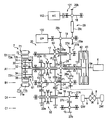
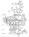
- Cross section of motor 7 and transmission 20 Conceptual diagram of internal configuration of motor 7 and transmission 20
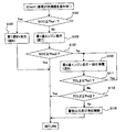
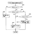
- the figure which shows the zone of SOC of the battery 3 Flowchart of a first embodiment of control performed by the control device 2 for a vehicle traveling at extremely low speed.
- FIG. 1 is a block diagram showing an internal configuration of an HEV according to an embodiment. 1 includes an engine (ENG) 6 as a driving source, a motor (MOT) 7 as a driving source, a battery (BATT) 3, and an inverter (INV). 101, a transmission (T / M) 20, an oil pump (O / P) 122, an air conditioner compressor (A / C) 112, a wheel speed sensor WS, and a control device 2.
- ENG engine
- MOT motor
- ISV inverter
- FIG. 2 is a cross-sectional view of the motor 7 and the transmission 20.
- FIG. 3 is a conceptual diagram of the internal configuration of the motor 7 and the transmission 20.
- the engine 6 is, for example, a gasoline engine or a diesel engine.
- a first clutch 41 (first connecting / disconnecting means) 42 and a second clutch (second connecting / disconnecting means) 42 of the transmission 20 are connected to the crankshaft 6 a of the engine 6. Is provided.
- the motor 7 is a three-phase brushless DC motor, and includes a stator 71 composed of 3n armatures 71a, and a rotor 72 arranged to face the stator 71.
- Each armature 71a includes an iron core 71b and a coil 71c wound around the iron core 71b.
- the armature 71a is fixed to a casing (not shown) and is arranged at substantially equal intervals in the circumferential direction around the rotation axis. Yes.
- the 3n coils 71c constitute n sets of U-phase, V-phase, and W-phase three-phase coils.
- the rotor 72 has an iron core 72a and n permanent magnets 72b arranged at almost equal intervals around the rotation axis, and the polarities of two adjacent permanent magnets 72b are different from each other.
- the fixing portion 72c for fixing the iron core 72a has a hollow cylindrical shape, is disposed on the outer peripheral side of the ring gear 35 of the planetary gear mechanism 30 described later, and is connected to the sun gear 32 of the planetary gear mechanism 30. Accordingly, the rotor 72 is configured to rotate integrally with the sun gear 32 of the planetary gear mechanism 30.
- the planetary gear mechanism 30 includes a sun gear 32, a ring gear 35 that is arranged coaxially with the sun gear 32 and that surrounds the sun gear 32, and a planetary gear 34 that meshes with the sun gear 32 and the ring gear 35. And a carrier 36 that supports the planetary gear 34 so as to be capable of rotating and revolving. In this way, the sun gear 32, the ring gear 35, and the carrier 36 are configured to be differentially rotatable with respect to each other.
- the ring gear 35 is provided with a brake mechanism 61 (synchronizer mechanism) having a synchronization mechanism (synchronizer mechanism) and configured to stop (lock) the rotation of the ring gear 35.
- a lock mechanism may be used instead of the brake mechanism 61.
- the motor 7 is connected to the battery 3 via the inverter 101.
- the battery 3 has a plurality of power storage cells connected in series, and supplies a high voltage of, for example, 100 to 200V.
- the storage cell is, for example, a lithium ion battery or a nickel metal hydride battery.
- the SOC State of Charge
- the SOC indicating the storage state of the battery 3 is classified into four zones, C zone, B zone, A zone, and D zone, from the smallest to the largest
- the A zone is classified into three zones, the AL zone, the AM zone, and the AH zone, from the one with the smallest SOC to the one with the largest SOC, and is divided into six zones in total.
- the inverter 101 converts the DC voltage from the battery 3 into an AC voltage by the switching operation of the switching element and supplies a three-phase current to the motor 7. Further, the inverter 101 converts the AC voltage input during the regenerative operation of the motor 7 into a DC voltage and charges the battery 3. Therefore, the motor 7 is driven by the electric power supplied from the battery 3 and performs regenerative power generation by the rotation of the drive wheel DW and the power of the engine 6 during the deceleration traveling to charge the battery 3 (energy recovery). It is possible. The motor 7 is also used for starting the engine 6.
- the transmission 20 is a so-called twin clutch transmission for transmitting power from the engine 6 and / or the motor 7 to the drive wheels DW.
- the transmission 20 includes the first clutch 41 and the second clutch 42 described above, a planetary gear mechanism 30, and a plurality of transmission gear groups described later.
- a temperature sensor (not shown) for detecting the temperature of the second clutch 42 is provided in the vicinity of the second clutch 42. Data relating to the temperature of the second clutch 42 detected by the temperature sensor is sent to the control device 2.
- the transmission 20 includes a first main shaft 11 (first input shaft), a second main shaft 12, a connecting shaft 13, and a rotation axis A1 that are arranged on the same axis (rotation axis A1) as the crankshaft 6a of the engine 6.
- a counter shaft 14 output shaft
- a first intermediate shaft 15 rotatable around a rotation axis C1 arranged parallel to the rotation axis A1
- a second intermediate shaft 16 (second input shaft) that is rotatable about a rotation axis D1 arranged in parallel with the axis A1 and a reverse that is rotatable about a rotation axis E1 arranged in parallel with the rotation axis A1.
- a shaft 17 is provided.
- the first main shaft 11 is provided with a first clutch 41 on the engine 6 side, and a sun gear 32 of the planetary gear mechanism 30 and a rotor 72 of the motor 7 are attached to the opposite side of the engine 6 side. Accordingly, the first main shaft 11 is selectively connected to the crankshaft 6 a of the engine 6 by the first clutch 41 and directly connected to the motor 7 so that the power of the engine 6 and / or the motor 7 is transmitted to the sun gear 32. It is configured.
- the second main shaft 12 is configured to be shorter and hollow than the first main shaft 11, and is disposed so as to be relatively rotatable so as to cover the periphery of the first main shaft 11 on the engine 6 side.
- the second main shaft 12 is provided with a second clutch 42 on the engine 6 side, and an idle drive gear 27a is integrally attached to the opposite side to the engine 6 side. Accordingly, the second main shaft 12 is selectively connected to the crankshaft 6a of the engine 6 by the second clutch 42, and the power of the engine 6 is transmitted to the idle drive gear 27a.
- the connecting shaft 13 is configured to be shorter and hollow than the first main shaft 11, and is disposed so as to be relatively rotatable so as to cover the periphery of the first main shaft 11 on the side opposite to the engine 6 side. Further, a third speed drive gear 23 a is integrally attached to the connecting shaft 13 on the engine 6 side, and a carrier 36 of the planetary gear mechanism 30 is integrally attached to the opposite side of the engine 6 side. Therefore, the carrier 36 attached to the connecting shaft 13 and the third-speed drive gear 23a are configured to rotate integrally by the revolution of the planetary gear 34.
- the first main shaft 11 is provided with a fifth-speed drive gear 25 a that is rotatable relative to the first main shaft 11, and a reverse driven gear 28 b that rotates integrally with the first main shaft 11. Further, a first main shaft 11 and a third speed drive gear 23a or a fifth speed drive gear 25a are connected or released between the third speed drive gear 23a and the fifth speed drive gear 25a.
- a shift shifter 51 (first synchronization device) is provided. When the first speed-shifting shifter 51 is in-gear at the third speed connection position, the first main shaft 11 and the third speed drive gear 23a are connected to rotate integrally and in-gear at the fifth speed connection position.
- the first main shaft 11 and the fifth speed drive gear 25a rotate integrally, and when the first speed change shifter 51 is in the neutral position, the first main shaft 11 has the third speed drive gear 23a and the fifth speed drive gear 25a. It rotates relative to the drive gear 25a.
- the sun gear 32 attached to the first main shaft 11 and the carrier 36 connected to the third speed drive gear 23a by the connecting shaft 13 are provided.
- the ring gear 35 While rotating integrally, the ring gear 35 also rotates together, and the planetary gear mechanism 30 is united.
- the first shifter 51 is in the neutral position and the brake mechanism 61 is connected, the ring gear 35 is locked and the rotation of the sun gear 32 is decelerated and transmitted to the carrier 36.
- a first idle driven gear 27b that meshes with an idle drive gear 27a attached to the second main shaft 12 is integrally attached to the first intermediate shaft 15.
- the second intermediate shaft 16 is integrally attached with a second idle driven gear 27c that meshes with the first idle driven gear 27b attached to the first intermediate shaft 15.
- the second idle driven gear 27c constitutes the first idle gear train 27A together with the idle drive gear 27a and the first idle driven gear 27b described above.
- the second intermediate shaft 16 is rotatable relative to the second intermediate shaft 16 at positions corresponding to the third speed drive gear 23a and the fifth speed drive gear 25a provided around the first main shaft 11, respectively.
- a second speed drive gear 22a and a fourth speed drive gear 24a are provided.
- the second intermediate shaft 16 includes a second intermediate shaft 16 and a second speed drive gear 22a or a fourth speed drive gear 24a between the second speed drive gear 22a and the fourth speed drive gear 24a.
- a second shifter 52 (second synchronizer).
- the second shifter 52 shifts in-gear at the second speed connection position
- the second intermediate shaft 16 and the second speed drive gear 22a rotate together
- the second shifter 52 shifts to the fourth speed.
- the second intermediate shaft 16 and the fourth speed drive gear 24a rotate together, and when the second shifter shifter 52 is in the neutral position, the second intermediate shaft 16 is in the second speed.
- the drive gear 22a and the fourth speed drive gear 24a rotate relative to each other.
- a first shared driven gear 23b, a second shared driven gear 24b, a parking gear 21, and a final gear 26a are integrally attached to the counter shaft 14 in order from the side opposite to the engine 6 side.
- the first shared driven gear 23b meshes with the third speed drive gear 23a attached to the connecting shaft 13 to form the third speed gear pair 23 together with the third speed drive gear 23a
- the second speed gear pair 22 is configured together with the second speed drive gear 22a by meshing with the second speed drive gear 22a provided on the intermediate shaft 16.
- the second shared driven gear 24b meshes with the fifth speed drive gear 25a provided on the first main shaft 11 to form the fifth speed gear pair 25 together with the fifth speed drive gear 25a, and the second intermediate shaft.
- a third idle driven gear 27d that meshes with the first idle driven gear 27b attached to the first intermediate shaft 15 is integrally attached to the reverse shaft 17.
- the third idle driven gear 27d constitutes a second idle gear train 27B together with the above-described idle drive gear 27a and first idle driven gear 27b.
- the reverse shaft 17 is provided with a reverse drive gear 28 a that meshes with a reverse driven gear 28 b attached to the first main shaft 11 so as to be rotatable relative to the reverse shaft 17.
- the reverse drive gear 28a constitutes the reverse gear train 28 together with the reverse driven gear 28b.
- a reverse shifter 53 for connecting or releasing the reverse shaft 17 and the reverse drive gear 28a is provided on the opposite side of the reverse drive gear 28a from the engine 6 side.
- the first shifter 51, the second shifter 52, and the reverse shifter 53 use a clutch mechanism having a synchronizing mechanism (synchronizer mechanism) that matches the rotational speed of the shaft to be connected with the gear.
- a synchronizing mechanism synchronizer mechanism
- the transmission 20 configured as described above has an odd-numbered gear group consisting of a third speed drive gear 23a and a fifth speed drive gear 25a on the first main shaft 11, which is one of the two transmission shafts.
- a first gear group) and an even-stage gear group (first gear group) composed of a second-speed drive gear 22a and a fourth-speed drive gear 24a on the second intermediate shaft 16, which is the other of the two transmission shafts. 2 gear groups) are provided.
- the even-numbered gear group of the transmission 20 may further include a sixth-speed driving gear
- the odd-numbered gear group may further include a seventh-speed driving gear.
- the transmission 20 includes first to fifth transmission paths described below.
- the crankshaft 6a of the engine 6 includes the first main shaft 11, the planetary gear mechanism 30, the connecting shaft 13, and the third speed gear pair 23 (third speed drive gear 23a, first common use).
- This is a transmission path connected to the drive wheel DW via the driven gear 23b), the counter shaft 14, the final gear 26a, the differential gear mechanism 8, and the drive shaft 9.
- the reduction gear ratio of the planetary gear mechanism 30 is set so that the engine torque transmitted to the drive wheels DW via the first transmission path corresponds to the first speed. That is, the reduction ratio obtained by multiplying the reduction ratio of the planetary gear mechanism 30 and the reduction ratio of the third speed gear pair 23 is set to be equivalent to the first speed.
- the crankshaft 6a of the engine 6 has the second main shaft 12, the first idle gear train 27A (the idle drive gear 27a, the first idle driven gear 27b, the second idle driven gear 27c), the second 2 intermediate shaft 16, second speed gear pair 22 (second speed drive gear 22a, first shared driven gear 23b) or fourth speed gear pair 24 (fourth speed drive gear 24a, second shared driven gear) 24b), a transmission path connected to the drive wheel DW via the counter shaft 14, the final gear 26a, the differential gear mechanism 8, and the drive shaft 9.
- the first idle gear train 27A the idle drive gear 27a, the first idle driven gear 27b, the second idle driven gear 27c
- the second 2 intermediate shaft 16 second speed gear pair 22 (second speed drive gear 22a, first shared driven gear 23b) or fourth speed gear pair 24 (fourth speed drive gear 24a, second shared driven gear) 24b
- a transmission path connected to the drive wheel DW via the counter shaft 14, the final gear 26a, the differential gear mechanism 8, and the drive shaft 9.
- the crankshaft 6a of the engine 6 is used for the first main shaft 11, the third speed gear pair 23 (the third speed drive gear 23a, the first shared driven gear 23b) or the fifth speed.
- the gear pair 25 (the fifth speed drive gear 25a and the second shared driven gear 24b)
- the counter shaft 14 the final gear 26a, the differential gear mechanism 8, and the drive shaft 9, without the planetary gear mechanism 30, It is a transmission path coupled to the drive wheel DW.
- the motor 7 is connected to the planetary gear mechanism 30 or the third speed gear pair 23 (third speed drive gear 23a, first shared driven gear 23b) or fifth speed gear pair 25 ( The fifth speed drive gear 25a, the second shared driven gear 24b), the counter shaft 14, the final gear 26a, the differential gear mechanism 8, and the drive shaft 9 are transmission paths connected to the drive wheels DW.
- crankshaft 6a of the engine 6 is connected to the second main shaft 12, the second idle gear train 27B (idle drive gear 27a, first idle driven gear 27b, third idle driven gear 27d), reverse Shaft 17, reverse gear train 28 (reverse drive gear 28a, reverse driven gear 28b), planetary gear mechanism 30, connecting shaft 13, third speed gear pair 23 (third speed drive gear 23a, first common use)
- This is a transmission path connected to the drive wheel DW via the driven gear 23b), the counter shaft 14, the final gear 26a, the differential gear mechanism 8, and the drive shaft 9.
- the oil pump 122 is mounted on the oil pump auxiliary shaft 19 arranged in parallel with the rotation axes A1 to E1 of the transmission 20 so as to be rotatable integrally with the oil pump auxiliary shaft 19.
- An oil pump driven gear 28c meshing with the reverse drive gear 28a and an air conditioner drive gear 29a are attached to the oil pump auxiliary shaft 19 so as to be integrally rotatable, and the engine 6 that rotates the first main shaft 11 and // The power of the motor 7 is transmitted.
- the air conditioner compressor 112 is provided via an air conditioner clutch 121 on the air conditioner auxiliary shaft 18 arranged in parallel with the rotation axes A1 to E1.
- An air conditioner driven gear 29b to which power is transmitted from an air conditioner drive gear 29a via a chain 29c is attached to the air conditioner auxiliary shaft 18 so as to be integrally rotatable with the air conditioner auxiliary shaft 18, and an oil pump auxiliary shaft 19 is provided.
- the power of the engine 6 and / or the motor 7 is transmitted through an air conditioner transmission mechanism 29 including an air conditioner drive gear 29a, a chain 29c, and an air conditioner driven gear 29b.
- the air conditioner compressor 112 is configured such that power transmission can be interrupted by connecting and disconnecting the air conditioner clutch 121 by an air conditioner operating solenoid (not shown).
- Wheel speed sensor WS detects the rotational speed of drive shaft 9.
- the rotational speed of the drive shaft 9 is equal to the rotational speed of the drive wheel DW.
- a signal indicating the rotational speed detected by the wheel speed sensor WS is sent to the control device 2.
- the control device 2 controls the engine 6, the motor 7, and the transmission 20. That is, the control device 2 controls the engine 6, the signal that controls the motor 7, the signal that controls the first shifter 51, the second shifter 52, and the reverse shifter 53 of the transmission 20, and A signal for controlling connection (locking) and release (neutral) of the brake mechanism 61, a signal for controlling engagement or disengagement of the air conditioner clutch 121, and the like are output. Further, the control device 2 includes the rotation speed of the drive wheel DW detected by the wheel speed sensor WS, the SOC of the battery 3, the accelerator pedal opening (AP opening), the state of the air conditioner switch, the shift position of the transmission 20, And the information regarding the temperature etc. of the 2nd clutch 42 of the transmission 20 is input. Further, the control device 2 detects the connection / disconnection state of the brake mechanism 61 and the positions of the first shifter 51 and the second shifter 52.
- control device 2 derives the vehicle speed (current vehicle speed) based on the rotational speed of the drive wheel DW detected by the wheel speed sensor WS, and calculates the average vehicle speed from the derived vehicle speed. Further, the control device 2 derives the required driving force based on the AP opening degree and the vehicle speed. Furthermore, the control device 2 determines the traveling state of the vehicle based on the current vehicle speed, the average vehicle speed, the required driving force, and the like. By this determination, the control device 2 can determine whether or not the vehicle is traveling on a congested road.
- the control device 2 controls the operation / stop of the air conditioner compressor 112 (engagement / release of the air conditioner clutch 121).
- the control device 2 includes an air-conditioning temperature setting switch for setting a set temperature of the air-conditioning temperature (cooling temperature), an air-conditioning switch for turning on / off the air-conditioning operation, and a rotation speed sensor (not shown) for detecting the shaft rotation speed of the counter shaft 14. ), And PWM is used to start / stop the air conditioner compressor 112 (engagement / release of the air conditioner clutch 121) so that the vehicle interior temperature is adjusted to the set temperature during the air conditioning operation (while the air conditioner switch 135 is on). (Pulse Width Modulation) Control.
- the control device 2 controls connection / disconnection of the first clutch 41 and the second clutch 42 of the transmission 20 and connects the brake mechanism 61, the first shifter 51, the second shifter 52, and the reverse shifter 53. By controlling (pre-shifting) the position, the vehicle can perform first to fifth speed traveling and reverse traveling with the engine 6.
- the control device 2 engages the first clutch 41 and connects the brake mechanism 61 so that the driving force is transmitted to the drive wheels DW via the first transmission path. Further, when the vehicle travels at the second speed, the control device 2 is driven through the second transmission path by engaging the second clutch 42 and in-gearing the second shifter shifter 52 at the second speed connection position. The force is transmitted to the drive wheel DW. Further, when the vehicle travels at the third speed, the control device 2 is driven through the third transmission path by engaging the first clutch 41 and in-gearing the first shifter 51 at the third speed connection position. The force is transmitted to the drive wheel DW.
- the control device 2 when the vehicle travels in the fourth speed, the control device 2 is driven through the second transmission path by engaging the first clutch 41 and in-gearing the second shifter shifter 52 at the fourth speed connection position. The force is transmitted to the drive wheel DW. Further, when the vehicle travels in the fifth speed, the control device 2 in-gears the first shifter shifter 51 at the fifth speed connection position, so that the driving force is transmitted to the drive wheels DW via the third transmission path. The Furthermore, when the vehicle travels backward, the control device 2 engages the second clutch 42 and connects the reverse shifter 53, whereby the reverse travel is performed via the fifth transmission path.
- the motor 7 can assist or regenerate by connecting the brake mechanism 61 or pre-shifting the first and second shifter shifters 51 and 52 while the engine is running. Further, even during idling, the engine 6 can be started by the motor 7 and the battery 3 can be charged. Further, the first and second clutches 41 and 42 can be disconnected and the EV 7 can be driven by the motor 7.
- the EV travel mode includes a first speed EV mode in which the first and second clutches 41 and 42 are disconnected and the brake mechanism 61 is connected to travel via the fourth transmission path, and the first speed change mode.
- the third speed EV mode that travels through the fourth transmission path by in-gearing the shifter 51 at the third-speed connection position, and the fourth speed by in-gearing the first shifter 51 at the fifth-speed connection position.
- the air conditioner compressor 112 since the air conditioner compressor 112 is connected to the first main shaft 11, the air conditioner compressor 112 can be operated because the first main shaft 11 inevitably rotates while traveling with an odd number of gears. In order to operate the air conditioner compressor 112 while traveling in gear, the first main shaft 11 needs to be rotated.
- extremely low speed traveling is traveling at a vehicle speed that requires the clutch to be in a half-clutch state when the vehicle travels with power from the engine 6.
- FIG. 5 is a flowchart of a first embodiment of control performed by the control device 2 for a vehicle traveling at an extremely low speed. As shown in FIG. 5, when it is determined that the vehicle is traveling on a congested road, the control device 2 determines whether or not the SOC of the battery 3 is equal to or greater than a first threshold value Ths1 (step S101).
- the first threshold Ths1 is, for example, the lowest value of the AH zone shown in FIG.
- step S101 when the SOC of the battery 3 is equal to or higher than the first threshold Ths1 (SOC ⁇ Ths1), the process proceeds to step S103, and when the SOC is less than the first threshold Ths1 (SOC ⁇ Ths1), step S105 is performed. Proceed to
- step S103 the control device 2 drives the transmission 20 and the motor 7 so that the vehicle travels at the first speed EV.
- FIG. 6 is a conceptual diagram showing a power transmission path in the transmission 20 when the vehicle travels at the first speed EV. As shown in FIG. 6, when the vehicle travels at the first speed EV, the control device 2 disconnects the first and second clutches 41 and 42 of the transmission 20 and connects the brake mechanism 61. Further, the control device 2 controls the motor 7 so as to output the required driving force.
- step S105 the control device 2 drives the transmission 20 and the engine 6 so that the vehicle travels in the first speed engine.
- FIG. 7 is a conceptual diagram showing a power transmission path in the transmission 20 when the vehicle travels in the first speed engine. As shown in FIG. 7, when the vehicle travels in the first speed engine, the control device 2 first fastens the second clutch 42 of the transmission 20 with the brake mechanism 61 connected, The engine 6 is started by a part. Thereafter, the control device 2 disconnects the second clutch 42 with the brake mechanism 61 connected, and fastens the first clutch 41 in a half-clutch state.
- the degree of engagement of the first clutch 41 is controlled by the control device 2 in accordance with the balance between the required driving force, the first speed reduction ratio, and the rotational speed of the engine 6. Further, the rotational speed of the engine 6 is the rotational speed on the BSFC bottom line, which is a line connecting the operating points of the engine 6 having the best fuel consumption rate, or a predetermined speed required for the engine 6 to keep running without being stalled. The number of revolutions.
- step S107 the control device 2 determines whether or not the SOC of the battery 3 is greater than or equal to the second threshold Ths2 (step S107).
- the second threshold Ths2 is, for example, the maximum value of the B zone shown in FIG.
- SOC ⁇ Ths2 the second threshold value
- step S109 the control device 2 drives the transmission 20 and the engine 6 so that the vehicle travels in the second speed engine.
- FIG. 8 is a conceptual diagram showing a power transmission path in the transmission 20 when the vehicle travels in the second speed engine.
- the control device 2 in-gears (second speed preshift) the second shifter shifter 52 at the second speed connection position, and then the first clutch 41 is fastened, the second clutch 42 is fastened in a half-clutch state, and the brake mechanism 61 is released.
- the degree of engagement of the second clutch 42 is controlled by the control device 2 in accordance with the balance between the required driving force, the speed reduction ratio of the second speed, and the rotational speed of the engine 6.
- the first clutch 41 is engaged and the brake mechanism 61 is in a released state, a part of the power of the engine 6 is used for regenerative power generation by the motor 7. As a result, the battery 3 is charged.
- step S111 the control device 2 determines whether or not the temperature TCL2 of the second clutch 42 is equal to or lower than the first threshold value Tht1 (step S111).
- step S111 when the temperature TCL2 of the second clutch 42 is equal to or lower than the first threshold value Tht1 (TCL2 ⁇ Tht1), the process returns to step S109, and when it is larger than the first threshold value Tht1 (TCL2> Tht1).
- step S113 the control device 2 determines whether or not the temperature TCL2 of the second clutch 42 is equal to or lower than the second threshold value Tht2.
- the value of the second threshold value Tht2 is higher than the first threshold value Tht1.
- step S115 when the temperature TCL2 of the second clutch 42 is higher than the second threshold value Tht2 (TCL2> Tht2), the process proceeds to step S115.
- step S115 the control device 2 controls to output a warning sound from a speaker (not shown) or display a warning message on a display (not shown) for the purpose of notifying the driver of the vehicle.
- the control device 2 performs control for cooling the second clutch 42.
- FIG. 9 is a flowchart of a second embodiment of control performed by the control device 2 for a vehicle traveling at extremely low speed.
- the control device 2 determines whether or not the SOC of the battery 3 is equal to or higher than a first threshold Ths1 (step S201).
- the first threshold Ths1 is, for example, the lowest value of the AH zone shown in FIG.
- step S201 when the SOC of the battery 3 is equal to or greater than the first threshold Ths1 (SOC ⁇ Ths1), the process proceeds to step S203, and when the SOC is less than the first threshold Ths1 (SOC ⁇ Ths1), step S205 is performed. Proceed to
- step S203 the control device 2 drives the transmission 20 and the motor 7 so that the vehicle travels at the first speed EV.
- the power transmission path in the transmission 20 at this time is as shown in FIG.
- step S205 control device 2 determines whether or not the SOC of battery 3 is equal to or greater than second threshold value Ths2.
- the second threshold Ths2 is, for example, the maximum value of the B zone shown in FIG.
- step S207 the control device 2 drives the transmission 20 and the engine 6 so that the vehicle travels in the first speed engine.
- the power transmission path in the transmission 20 at this time is as shown in FIG.
- step S209 it is determined whether or not the temperature TCL2 of the second clutch 42 is equal to or lower than a threshold value Tht.
- Tht a threshold value
- the process proceeds to step S211.
- the control device 2 drives the transmission 20 and the engine 6 so that the vehicle travels in the second speed engine.
- the power transmission path in the transmission 20 at this time is as shown in FIG.
- FIG. 10 is a flowchart of a third embodiment of control performed by the control device 2 for a vehicle traveling at extremely low speed.
- the control device 2 determines whether or not the SOC of the battery 3 is equal to or higher than a first threshold Ths1 (step S301).
- the first threshold Ths1 is, for example, the lowest value of the AH zone shown in FIG.
- step S301 when the SOC of the battery 3 is equal to or higher than the first threshold Ths1 (SOC ⁇ Ths1), the process proceeds to step S303, and when the SOC is less than the first threshold Ths1 (SOC ⁇ Ths1), step S305 is performed. Proceed to
- step S303 the control device 2 drives the transmission 20 and the motor 7 so that the vehicle travels at the first speed EV.
- the power transmission path in the transmission 20 at this time is as shown in FIG.
- step S305 control device 2 determines whether or not the SOC of battery 3 is equal to or greater than second threshold value Ths2.
- the second threshold Ths2 is, for example, the maximum value of the B zone shown in FIG.
- step S307 the control device 2 drives the transmission 20 and the engine 6 so that the vehicle travels in the first speed engine.
- the power transmission path in the transmission 20 at this time is as shown in FIG.
- step S309 it is determined whether or not the temperature TCL2 of the second clutch 42 is equal to or lower than the first threshold value Tht1.
- the process proceeds to step S311 and when the temperature is higher than the first threshold value Tht1 (TCL2> Tht1).
- step S313 the control device 2 drives the transmission 20 and the engine 6 so that the vehicle travels in the second speed engine.
- the power transmission path in the transmission 20 at this time is as shown in FIG.
- step S313 the control device 2 determines whether or not the temperature TCL2 of the second clutch 42 is equal to or lower than the second threshold value Tht2.
- the value of the second threshold value Tht2 is higher than the first threshold value Tht1.
- the process proceeds to step S311 and is larger than the second threshold value Tht2 (TCL2> Tht2). Advances to step S315.
- step S315 the control device 2 controls to output a warning sound from a speaker (not shown) or display a warning message on a display (not shown) for the purpose of notifying the driver of the vehicle.
- the control device 2 performs control for cooling the second clutch 42.
- the control device 2 gradually reduces the clutch torque in the first or second clutch 41, 42 of the transmission 20 (step S317).
- step S319) the control device 2 determines whether or not the vehicle speed is 0 (step S319). If the vehicle speed is 0, the process proceeds to step S321, and if the vehicle speed is not 0, the process proceeds to step S311. In step S321, the control device 2 turns on a brake for braking the vehicle.
- FIG. 11 is a flowchart of a fourth embodiment of control performed by the control device 2 for a vehicle traveling at an extremely low speed.
- the control device 2 determines whether the operation requested of the air conditioner is large based on the state of the air conditioner switch. It discriminate
- step S403 the control device 2 determines whether or not the SOC of the battery 3 is equal to or greater than the first threshold value Ths1.
- the first threshold Ths1 is, for example, the lowest value of the AH zone shown in FIG.
- step S405 when the SOC of the battery 3 is equal to or greater than the first threshold Ths1 (SOC ⁇ Ths1), the process proceeds to step S405, and when the SOC is less than the first threshold Ths1 (SOC ⁇ Ths1), step S407 is performed. Proceed to
- step S405 the control device 2 drives the transmission 20 and the motor 7 so that the vehicle travels at the first speed EV.
- the power transmission path in the transmission 20 at this time is as shown in FIG.
- step S407 control device 2 determines whether or not the SOC of battery 3 is greater than or equal to second threshold value Ths2.
- the second threshold Ths2 is, for example, the maximum value of the B zone shown in FIG.
- step S409 the control device 2 drives the transmission 20 and the engine 6 so that the vehicle travels in the first speed engine.
- the power transmission path in the transmission 20 at this time is as shown in FIG.
- step S411 it is determined whether or not the temperature TCL2 of the second clutch 42 is equal to or lower than a threshold value Tht. If it is determined in step S411 that the temperature TCL2 of the second clutch 42 is equal to or lower than the threshold value Tht (TCL2 ⁇ Tht), the process proceeds to step S413. If the temperature TCL2 is greater than the threshold value Tht (TCL2> Tht), the process proceeds to step S409. move on.
- step S413 the control device 2 drives the transmission 20 and the engine 6 so that the vehicle travels in the second speed engine. The power transmission path in the transmission 20 at this time is as shown in FIG.
- step S401 determines whether or not the required rotational speed of the oil pump auxiliary shaft 19 of the transmission 20 based on the air conditioner request operation is equal to or higher than the rotational speed of the first main shaft 11 rotated by the engine 6. To do.
- step S415 when the required rotational speed of the auxiliary shaft 19 for the oil pump is equal to or higher than the rotational speed of the first main spindle 11, the process proceeds to step S411, and when it is less than the rotational speed of the first main spindle 11, the process proceeds to step S403. .
- step S411 when the second speed engine traveling shown in step S413 is performed, the control device 2 determines that the rotational speed of the oil pump auxiliary shaft 19 becomes the required rotational speed. The rotational speed of the engine 6 is controlled.
- the vehicle speed when the vehicle is creeping is set to a vehicle speed at which the engine 6 can be started by the driving force of the motor 7 when shifting from EV traveling to first speed engine traveling.
- the transmission 20 includes an odd-numbered stage gear disposed on the first main shaft 11 that is an input shaft to which a motor 7 of a twin clutch transmission is connected, and a second intermediate shaft that is an input shaft to which the motor 7 is not connected.
- the even-numbered gear is arranged at 16
- the present invention is not limited to this.
- the even-numbered gear is arranged at the first main shaft 11, which is the input shaft to which the motor 7 is connected, and the input shaft is not connected to the motor 7. 2
- An odd-numbered gear may be arranged on the intermediate shaft 16.
- a first common driven gear 23b, a fourth speed drive gear 24a, and a fifth speed are configured such that the driven gear attached to the counter shaft 14 is meshed with the second speed driving gear 22a and the third speed driving gear 23a.
- the second shared driven gear 24b meshed with the speed drive gear 25a is combined, the present invention is not limited to this, and a plurality of driven gears meshed with each gear may be provided.
- the planetary gear mechanism 30 is exemplified as the first speed drive gear, but the present invention is not limited to this, and the first speed drive gear may be provided in the same manner as the third speed drive gear 23a.
- gears may be provided as sixth, eighth,...
- the first main shaft 11 is further provided with a seventh speed drive gear 97a
- the second intermediate shaft 16 is further provided with a sixth speed drive gear 96a
- the counter shaft 14 is provided with a seventh speed drive gear.
- a third shared driven gear 96b that meshes with the sixth speed drive gear 96a and that constitutes the sixth speed gear pair 26. It has been.
- reference numeral 51 ⁇ / b> A is a shift shifter for connecting or releasing the first main shaft 11 and the third speed driving gear 23 a or the seventh speed driving gear 97 a
- reference numeral 51 ⁇ / b> B is the first main shaft 11.
- a reference numeral 52A is a shift shifter 52A for connecting or releasing the second speed drive gear 22a or the sixth speed drive gear 96a.
- Reference numeral 52B denotes a shift shifter for connecting or releasing the second intermediate shaft 16 and the fourth speed drive gear 24a.
Landscapes
- Engineering & Computer Science (AREA)
- Mechanical Engineering (AREA)
- Transportation (AREA)
- Combustion & Propulsion (AREA)
- Chemical & Material Sciences (AREA)
- Power Engineering (AREA)
- Automation & Control Theory (AREA)
- Thermal Sciences (AREA)
- Physics & Mathematics (AREA)
- Life Sciences & Earth Sciences (AREA)
- Sustainable Energy (AREA)
- Sustainable Development (AREA)
- Electric Propulsion And Braking For Vehicles (AREA)
- Hybrid Electric Vehicles (AREA)
Abstract
Description
請求項4に記載の発明のハイブリッド車両の制御装置によれば、内燃機関の動力の一部が前記第1断接手段及び前記第1同期装置を介して電動機に伝達されることによって、電動機は回生発電する。このため、蓄電器を充電することができる。
請求項5~8に記載の発明のハイブリッド車両の制御装置によれば、第2断接手段の温度上昇を防ぐことができる。
請求項11に記載の発明のハイブリッド車両の制御装置によれば、蓄電器が第1蓄電レベルを超えた蓄電状態に戻った際には、電動機から動力のみによって走行する形態に戻すことができる。
請求項12に記載の発明のハイブリッド車両の制御装置及び請求項15に記載の発明のハイブリッド車両の制御方法によれば、ハイブリッド車両が極低速走行を行う際、蓄電器の蓄電状態又はエアコンに要求される動作に適した走行形態に切り替えることができる。
ここで、第1共用従動ギヤ23bは、連結軸13に取り付けられた第3速用駆動ギヤ23aと噛合して第3速用駆動ギヤ23aと共に第3速用ギヤ対23を構成し、第2中間軸16に設けられた第2速用駆動ギヤ22aと噛合して第2速用駆動ギヤ22aと共に第2速用ギヤ対22を構成する。
第2共用従動ギヤ24bは、第1主軸11に設けられた第5速用駆動ギヤ25aと噛合して第5速用駆動ギヤ25aと共に第5速用ギヤ対25を構成し、第2中間軸16に設けられた第4速用駆動ギヤ24aと噛合して第4速用駆動ギヤ24aと共に第4速用ギヤ対24を構成する。
ファイナルギヤ26aは差動ギヤ機構8と噛合して、差動ギヤ機構8は、駆動軸9を介して駆動輪DWに連結されている。従って、カウンタ軸14に伝達された動力はファイナルギヤ26aから差動ギヤ機構8、駆動軸9、駆動輪DWへと出力される。
(1)第1伝達経路は、エンジン6のクランク軸6aが、第1主軸11、遊星歯車機構30、連結軸13、第3速用ギヤ対23(第3速用駆動ギヤ23a、第1共用従動ギヤ23b)、カウンタ軸14、ファイナルギヤ26a、差動ギヤ機構8、駆動軸9を介して、駆動輪DWに連結される伝達経路である。ここで、遊星歯車機構30の減速比は、第1伝達経路を介して駆動輪DWに伝達されるエンジントルクが第1速相当となるように設定されている。即ち、遊星歯車機構30の減速比と第3速用ギヤ対23の減速比をかけ合わせた減速比が第1速相当となるように設定されている。
図5は、極低速走行中の車両の制御装置2が行う制御の第1実施例のフローチャートである。図5に示すように、制御装置2は、車両が渋滞路を走行中と判別したとき、バッテリ3のSOCが、第1しきい値Ths1以上か否かを判別する(ステップS101)。第1しきい値Ths1は、例えば、図4に示したA-Hゾーンの最低値である。ステップS101での判別の結果、バッテリ3のSOCが第1しきい値Ths1以上(SOC≧Ths1)のときはステップS103に進み、第1しきい値Ths1未満(SOC<Ths1)のときはステップS105に進む。
図9は、極低速走行中の車両の制御装置2が行う制御の第2実施例のフローチャートである。図9に示すように、制御装置2は、車両が渋滞路を走行中と判別したとき、バッテリ3のSOCが、第1しきい値Ths1以上か否かを判別する(ステップS201)。第1しきい値Ths1は、例えば、図4に示したA-Hゾーンの最低値である。ステップS201での判別の結果、バッテリ3のSOCが第1しきい値Ths1以上(SOC≧Ths1)のときはステップS203に進み、第1しきい値Ths1未満(SOC<Ths1)のときはステップS205に進む。
図10は、極低速走行中の車両の制御装置2が行う制御の第3実施例のフローチャートである。図10に示すように、制御装置2は、車両が渋滞路を走行中と判別したとき、バッテリ3のSOCが、第1しきい値Ths1以上か否かを判別する(ステップS301)。第1しきい値Ths1は、例えば、図4に示したA-Hゾーンの最低値である。ステップS301での判別の結果、バッテリ3のSOCが第1しきい値Ths1以上(SOC≧Ths1)のときはステップS303に進み、第1しきい値Ths1未満(SOC<Ths1)のときはステップS305に進む。
図11は、極低速走行中の車両の制御装置2が行う制御の第4実施例のフローチャートである。図5に示すように、制御装置2は、車両が渋滞路を走行中と判別したとき、制御装置2は、エアコンスイッチの状態に基づいて、エアコンに要求されている動作が大きいか否かを判別する(ステップS401)。ステップS401での判別の結果、エアコン要求動作が小さいときはステップS403に進む。
例えば、変速機20は、ツインクラッチ式変速機のモータ7が接続された入力軸である第1主軸11に奇数段ギヤを配置し、モータ7が接続されていない入力軸である第2中間軸16に偶数段ギヤを配置したが、これに限定されず、モータ7が接続された入力軸である第1主軸11に偶数段ギヤを配置し、モータ7が接続されていない入力軸である第2中間軸16に奇数段ギヤを配置してもよい。
3 バッテリ
6 エンジン(内燃機関)
7 モータ(電動機)
8 差動ギヤ機構
9 駆動軸
DW 駆動輪
11 第1主軸(第1の入力軸)
12 第2主軸
13 連結軸
14 カウンタ軸(出力軸)
15 第1中間軸
16 第2中間軸(第2の入力軸)
17 リバース軸
18 エアコン用補機軸
19 オイルポンプ用補機軸
20 変速機
22a 第2速用駆動ギヤ
23a 第3速用駆動ギヤ
23b 第1共用従動ギヤ
24a 第4速用駆動ギヤ
24b 第2共用従動ギヤ
25a 第5速用駆動ギヤ
28 後進用ギヤ列
28a 後進用駆動ギヤ
28b リバース従動ギヤ
28c オイルポンプ用従動ギヤ
29 エアコン用伝達機構
29a エアコン用駆動ギヤ
29b エアコン用従動ギヤ
29c チェーン
30 遊星歯車機構
41 第1クラッチ(第1断接手段)
42 第2クラッチ(第2断接手段)
51 第1変速用シフター(第1同期装置)
52 第2変速用シフター(第2同期装置)
53 後進用シフター
61 ブレーキ機構(シンクロナイザー機構)
101 インバータ
WS 車輪速センサ
121 エアコン用クラッチ
122 オイルポンプ
112 エアコン用コンプレッサ
Claims (15)
- 内燃機関と電動機とを駆動源とするハイブリッド車両に用いられ、
前記内燃機関の機関出力軸及び前記電動機からの機械的動力を、前記電動機と係合する第1入力軸で受け、第1同期装置を介して複数の変速段のうちいずれか1つを係合状態にして、前記第1入力軸と前記ハイブリッド車両の駆動輪とを係合させることが可能な第1変速機構と、
前記機関出力軸からの機械的動力を第2入力軸で受け、第2同期装置を介して複数の変速段のうちいずれか1つを係合状態にして、前記第2入力軸と前記駆動輪とを係合させることが可能な第2変速機構と、
前記第1変速機構に対応して設けられ、前記機関出力軸と前記第1入力軸とを係合させることが可能な第1断接手段と、
前記第2変速機構に対応して設けられ、前記機関出力軸と前記第2入力軸とを係合させることが可能な第2断接手段と、
エアコン用クラッチを介して前記第1入力軸に連結され、前記電動機に電力を供給する蓄電器からの電力により動作するエアコン用コンプレッサと、を備えた前記ハイブリッド車両の制御装置であって、
前記電動機からの動力のみによって前記ハイブリッド車両が極低速走行時に、前記蓄電器の蓄電状態が第1蓄電レベル以下となったとき、又は、前記エアコン用コンプレッサに要求される回転数が所望回転数に満たないとき、前記第1断接手段を接続して前記電動機からの動力によって前記内燃機関を始動した後、前記第1断接手段又は前記第2断接手段を完全締結状態と完全開放状態の間で接続して、前記内燃機関からの動力を出力軸に伝達するよう前記変速機を制御することを特徴とする制御装置。 - 内燃機関と電動機とを駆動源とするハイブリッド車両に用いられ、
前記内燃機関の機関出力軸及び前記電動機からの機械的動力を、前記電動機と係合する第1入力軸で受け、第1同期装置を介して複数の変速段のうちいずれか1つを係合状態にして、前記第1入力軸と前記ハイブリッド車両の駆動輪とを係合させることが可能な第1変速機構と、
前記機関出力軸からの機械的動力を第2入力軸で受け、第2同期装置を介して複数の変速段のうちいずれか1つを係合状態にして、前記第2入力軸と前記駆動輪とを係合させることが可能な第2変速機構と、
前記第1変速機構に対応して設けられ、前記機関出力軸と前記第1入力軸とを係合させることが可能な第1断接手段と、
前記第2変速機構に対応して設けられ、前記機関出力軸と前記第2入力軸とを係合させることが可能な第2断接手段と、
エアコン用クラッチを介して前記第1入力軸に連結されるエアコン用コンプレッサと、を備えた前記ハイブリッド車両の制御装置であって、
前記電動機からの動力のみによって前記ハイブリッド車両が極低速走行時に、前記電動機に電力を供給する蓄電器の蓄電状態が第1蓄電レベル以下となったとき、又は、前記エアコン用コンプレッサに要求される回転数が所望回転数に満たないとき、前記第1断接手段を接続して前記電動機からの動力によって前記内燃機関を始動した後、前記第1断接手段又は前記第2断接手段を完全締結状態と完全開放状態の間で接続して、前記内燃機関からの動力を出力軸に伝達するよう前記変速機を制御することを特徴とする制御装置。 - 請求項1又は2に記載の制御装置であって、
前記内燃機関からの動力によって前記ハイブリッド車両が極低速走行時には、前記内燃機関の出力と前記被駆動部に対して要求される出力の偏差に応じて、前記第1断接手段又は前記第2断接手段の完全締結状態と完全開放状態の間の接続状態を決定することを特徴とする制御装置。 - 請求項1~3のいずれか一項に記載の制御装置であって、
前記蓄電器の蓄電状態が前記第1蓄電レベルよりも低い第2蓄電レベル以下となったとき、
前記第2断接手段を完全締結状態と完全開放状態の間で接続して、前記第2同期装置を介して前記内燃機関からの動力を前記出力軸に伝達すると共に、前記第1同期装置を開放して前記第1断接手段を接続することを特徴とする制御装置。 - 請求項1~4のいずれか一項に記載の制御装置であって、
前記第2断接手段の温度がしきい値を超えると、
前記第1断接手段を完全締結状態と完全開放状態の間で接続して、前記第1同期装置を介して前記内燃機関からの動力を前記出力軸に伝達すると共に、前記第2断接手段を切断することを特徴とする制御装置。 - 請求項1~5のいずれか一項に記載の制御装置であって、
前記第2断接手段の温度がしきい値を超えると、
前記第2断接手段の温度を下げるための冷却制御を行うことを特徴とする制御装置。 - 請求項6に記載の制御装置であって、
前記冷却制御は、前記ハイブリッド車両の運転者に対する報知であることを特徴とする制御装置。 - 請求項6に記載の制御装置であって、
前記冷却制御は、前記第2断接手段の完全締結状態と完全開放状態の間の接続状態を前記完全開放状態に近づけ、前記ハイブリッド車両が走行停止した際には制動装置を駆動することを特徴とする制御装置。 - 請求項1~8のいずれか一項に記載の制御装置であって、
前記ハイブリッド車両がクリープ走行時の車速は、電動機からの動力のみによる走行形態から前記内燃機関からの動力による走行形態に移行する際に、前記電動機の動力によって前記内燃機関を始動可能な車速であることを特徴とする制御装置。 - 請求項1~9のいずれか一項に記載の制御装置であって、
前記電動機からの動力によって前記内燃機関を始動する際、前記第1同期装置を開放した状態で前記第1断接手段を接続することを特徴とする制御装置。 - 請求項1~10のいずれか一項に記載の制御装置であって、
前記第2断接手段を完全締結状態と完全開放状態の間で接続して、前記第2同期装置を介して前記内燃機関からの動力を前記出力軸に伝達すると共に、前記第1同期装置を開放して前記第1断接手段を接続している状態のときに、前記蓄電器の蓄電状態が前記第1蓄電レベルを超えると、前記第1断接手段及び前記第2断接手段を切断して、前記電動機からの動力を前記出力軸に伝達するよう前記変速機を制御することを特徴とする制御装置。 - 内燃機関と電動機とを駆動源とするハイブリッド車両に用いられ、
前記内燃機関の機関出力軸及び前記電動機からの機械的動力を、前記電動機と係合する第1入力軸で受け、第1同期装置を介して複数の変速段のうちいずれか1つを係合状態にして、前記第1入力軸と前記ハイブリッド車両の駆動輪とを係合させることが可能な第1変速機構と、
前記機関出力軸からの機械的動力を第2入力軸で受け、第2同期装置を介して複数の変速段のうちいずれか1つを係合状態にして、前記第2入力軸と前記駆動輪とを係合させることが可能な第2変速機構と、
前記第1変速機構に対応して設けられ、前記機関出力軸と前記第1入力軸とを係合させることが可能な第1断接手段と、
前記第2変速機構に対応して設けられ、前記機関出力軸と前記第2入力軸とを係合させることが可能な第2断接手段と、を備えた前記ハイブリッド車両の制御装置であって、
前記電動機からの動力のみによって前記ハイブリッド車両が極低速走行時に、前記電動機に電力を供給する蓄電器の蓄電状態が第1蓄電レベル以下となったとき、前記第1断接手段を接続して前記電動機からの動力によって前記内燃機関を始動した後、前記第1断接手段又は前記第2断接手段を完全締結状態と完全開放状態の間で接続して、前記内燃機関からの動力を出力軸に伝達するよう前記変速機を制御することを特徴とする制御装置。 - 内燃機関と電動機とを駆動源とするハイブリッド車両に用いられ、
前記内燃機関の機関出力軸及び前記電動機からの機械的動力を、前記電動機と係合する第1入力軸で受け、第1同期装置を介して複数の変速段のうちいずれか1つを係合状態にして、前記第1入力軸と前記ハイブリッド車両の駆動輪とを係合させることが可能な第1変速機構と、
前記機関出力軸からの機械的動力を第2入力軸で受け、第2同期装置を介して複数の変速段のうちいずれか1つを係合状態にして、前記第2入力軸と前記駆動輪とを係合させることが可能な第2変速機構と、
前記第1変速機構に対応して設けられ、前記機関出力軸と前記第1入力軸とを係合させることが可能な第1断接手段と、
前記第2変速機構に対応して設けられ、前記機関出力軸と前記第2入力軸とを係合させることが可能な第2断接手段と、
エアコン用クラッチを介して前記第1入力軸に連結され、前記電動機に電力を供給する蓄電器からの電力により動作するエアコン用コンプレッサと、
前記内燃機関、前記電動機及び前記変速機を制御する制御装置と、を備えた前記ハイブリッド車両の制御方法であって、
前記制御装置は、
前記電動機からの動力のみによって前記ハイブリッド車両が極低速走行時に、前記蓄電器の蓄電状態が第1蓄電レベル以下となったとき、又は、前記エアコン用コンプレッサに要求される回転数が所望回転数に満たないとき、前記第1断接手段を接続して前記電動機からの動力によって前記内燃機関を始動した後、前記第1断接手段又は前記第2断接手段を完全締結状態と完全開放状態の間で接続して、前記内燃機関からの動力を出力軸に伝達するよう前記変速機を制御することを特徴とする制御方法。 - 内燃機関と電動機とを駆動源とするハイブリッド車両に用いられ、
前記内燃機関の機関出力軸及び前記電動機からの機械的動力を、前記電動機と係合する第1入力軸で受け、第1同期装置を介して複数の変速段のうちいずれか1つを係合状態にして、前記第1入力軸と前記ハイブリッド車両の駆動輪とを係合させることが可能な第1変速機構と、
前記機関出力軸からの機械的動力を第2入力軸で受け、第2同期装置を介して複数の変速段のうちいずれか1つを係合状態にして、前記第2入力軸と前記駆動輪とを係合させることが可能な第2変速機構と、
前記第1変速機構に対応して設けられ、前記機関出力軸と前記第1入力軸とを係合させることが可能な第1断接手段と、
前記第2変速機構に対応して設けられ、前記機関出力軸と前記第2入力軸とを係合させることが可能な第2断接手段と、
エアコン用クラッチを介して前記第1入力軸に連結されるエアコン用コンプレッサと、
前記内燃機関、前記電動機及び前記変速機を制御する制御装置と、を備えたハイブリッド車両の制御方法であって、
前記制御装置は、
前記電動機からの動力のみによって前記ハイブリッド車両が極低速走行時に、前記電動機に電力を供給する蓄電器の蓄電状態が第1蓄電レベル以下となったとき、又は、前記エアコン用コンプレッサに要求される回転数が所望回転数に満たないとき、前記第1断接手段を接続して前記電動機からの動力によって前記内燃機関を始動した後、前記第1断接手段又は前記第2断接手段を完全締結状態と完全開放状態の間で接続して、前記内燃機関からの動力を出力軸に伝達するよう前記変速機を制御することを特徴とする制御方法。 - 内燃機関と電動機とを駆動源とするハイブリッド車両に用いられ、
前記内燃機関の機関出力軸及び前記電動機からの機械的動力を、前記電動機と係合する第1入力軸で受け、第1同期装置を介して複数の変速段のうちいずれか1つを係合状態にして、前記第1入力軸と前記ハイブリッド車両の駆動輪とを係合させることが可能な第1変速機構と、
前記機関出力軸からの機械的動力を第2入力軸で受け、第2同期装置を介して複数の変速段のうちいずれか1つを係合状態にして、前記第2入力軸と前記駆動輪とを係合させることが可能な第2変速機構と、
前記第1変速機構に対応して設けられ、前記機関出力軸と前記第1入力軸とを係合させることが可能な第1断接手段と、
前記第2変速機構に対応して設けられ、前記機関出力軸と前記第2入力軸とを係合させることが可能な第2断接手段と、
前記内燃機関、前記電動機及び前記変速機を制御する制御装置と、を備えたハイブリッド車両の制御方法であって、
前記制御装置は、
前記電動機からの動力のみによって前記ハイブリッド車両が極低速走行時に、前記電動機に電力を供給する蓄電器の蓄電状態が所定の蓄電レベル以下となったとき、前記第1断接手段を接続して前記電動機からの動力によって前記内燃機関を始動した後、前記第1断接手段又は前記第2断接手段を完全締結状態と完全開放状態の間で接続して、前記内燃機関からの動力を出力軸に伝達するよう前記変速機を制御することを特徴とする制御方法。
Priority Applications (5)
| Application Number | Priority Date | Filing Date | Title |
|---|---|---|---|
| CN201180025576.8A CN102905929B (zh) | 2010-07-12 | 2011-07-12 | 混合动力车辆的控制装置以及控制方法 |
| RU2013101579/11A RU2534146C2 (ru) | 2010-07-12 | 2011-07-12 | Управляющий блок и способ управления гибридным транспортным средством |
| DE112011102328T DE112011102328T5 (de) | 2010-07-12 | 2011-07-12 | Hybridfahrzeugsteuereinheit und Steuerverfahren |
| JP2012524560A JPWO2012008461A1 (ja) | 2010-07-12 | 2011-07-12 | ハイブリッド車両の制御装置及び制御方法 |
| US13/700,304 US8892287B2 (en) | 2010-07-12 | 2011-07-12 | Hybrid vehicle control unit and control method |
Applications Claiming Priority (2)
| Application Number | Priority Date | Filing Date | Title |
|---|---|---|---|
| JP2010-157984 | 2010-07-12 | ||
| JP2010157984 | 2010-07-12 |
Publications (1)
| Publication Number | Publication Date |
|---|---|
| WO2012008461A1 true WO2012008461A1 (ja) | 2012-01-19 |
Family
ID=45469458
Family Applications (1)
| Application Number | Title | Priority Date | Filing Date |
|---|---|---|---|
| PCT/JP2011/065904 Ceased WO2012008461A1 (ja) | 2010-07-12 | 2011-07-12 | ハイブリッド車両の制御装置及び制御方法 |
Country Status (6)
| Country | Link |
|---|---|
| US (1) | US8892287B2 (ja) |
| JP (1) | JPWO2012008461A1 (ja) |
| CN (1) | CN102905929B (ja) |
| DE (1) | DE112011102328T5 (ja) |
| RU (1) | RU2534146C2 (ja) |
| WO (1) | WO2012008461A1 (ja) |
Cited By (8)
| Publication number | Priority date | Publication date | Assignee | Title |
|---|---|---|---|---|
| JP2013248995A (ja) * | 2012-05-31 | 2013-12-12 | Denso Corp | 車両駆動システムの制御装置 |
| JP2014094669A (ja) * | 2012-11-09 | 2014-05-22 | Honda Motor Co Ltd | 車両用駆動装置 |
| WO2014167893A1 (ja) * | 2013-04-10 | 2014-10-16 | ジヤトコ株式会社 | 摩擦要素の温度警告装置及び温度警告方法 |
| JP2015048065A (ja) * | 2013-09-04 | 2015-03-16 | 本田技研工業株式会社 | 動力出力装置の制御装置 |
| US20170001494A1 (en) * | 2013-12-16 | 2017-01-05 | Byd Company Limited | Air conditioning system, method for controlling the same and hybrid vehicle |
| CN110605976A (zh) * | 2019-10-23 | 2019-12-24 | 湖南恒润汽车有限公司 | 一种电动汽车车速模式切换系统 |
| CN111328367A (zh) * | 2017-11-09 | 2020-06-23 | 凯斯纽荷兰(中国)管理有限公司 | 双离合变速器中的改进或与双离合变速器相关的改进 |
| CN114801698A (zh) * | 2022-04-14 | 2022-07-29 | 浙江吉利控股集团有限公司 | 混合动力系统及汽车 |
Families Citing this family (20)
| Publication number | Priority date | Publication date | Assignee | Title |
|---|---|---|---|---|
| WO2011074482A1 (ja) | 2009-12-16 | 2011-06-23 | 本田技研工業株式会社 | ハイブリッド車両及びその制御方法 |
| CN104118424B (zh) * | 2009-12-16 | 2017-06-20 | 本田技研工业株式会社 | 混合动力车辆及其控制方法 |
| CN104709278B (zh) | 2009-12-22 | 2017-04-12 | 本田技研工业株式会社 | 混合动力车辆的控制装置 |
| CN102803038B (zh) * | 2010-03-31 | 2015-05-20 | 本田技研工业株式会社 | 混合动力车辆 |
| DE102011118687A1 (de) * | 2011-11-16 | 2013-05-16 | Audi Ag | Kraftfahrzeug |
| US20150336558A1 (en) * | 2013-01-11 | 2015-11-26 | Honda Motor Co., Ltd. | Hybrid-vehicle control device and control method |
| EP2990285B1 (en) * | 2013-04-22 | 2018-07-18 | Honda Motor Co., Ltd. | Hybrid vehicle control device |
| FR3020317B1 (fr) * | 2014-04-29 | 2016-04-29 | Renault Sa | Systeme de controle du mode de motricite d'un vehicule automobile hybride |
| US9493090B2 (en) * | 2014-08-14 | 2016-11-15 | Fca Us Llc | Dynamic battery system voltage control through mixed dynamic series and parallel cell connections |
| JP6343596B2 (ja) * | 2015-10-06 | 2018-06-13 | 本田技研工業株式会社 | デュアルクラッチ式変速機 |
| US11667174B2 (en) * | 2016-07-28 | 2023-06-06 | Volta Air Technology Inc. | Smart electric refrigeration system for vehicles |
| CN106080113B (zh) * | 2016-08-12 | 2018-08-03 | 苏州冷晨智能科技有限公司 | 电动汽车用电动压缩机系统及其控制方法 |
| CN107839438B (zh) * | 2016-09-21 | 2019-11-22 | 比亚迪股份有限公司 | 双驱压缩机切换控制方法、控制装置、控制系统以及车辆 |
| CN107839437B (zh) * | 2016-09-21 | 2019-11-08 | 比亚迪股份有限公司 | 双驱压缩机切换控制方法、控制装置、控制系统以及车辆 |
| CN107839427B (zh) * | 2016-09-21 | 2019-11-22 | 比亚迪股份有限公司 | 双驱压缩机切换控制方法、控制装置、控制系统以及车辆 |
| KR101813542B1 (ko) * | 2016-10-06 | 2018-01-30 | 현대자동차주식회사 | 하이브리드 차량 및 그 제어 방법 |
| KR101916073B1 (ko) * | 2016-10-21 | 2018-11-07 | 현대자동차 주식회사 | 하이브리드 전기자동차의 동력전달장치 |
| JP7156262B2 (ja) * | 2019-12-19 | 2022-10-19 | トヨタ自動車株式会社 | 電池搭載車両 |
| JP7435313B2 (ja) * | 2020-07-01 | 2024-02-21 | マツダ株式会社 | 車両 |
| DE102020118924A1 (de) * | 2020-07-17 | 2022-01-20 | Audi Aktiengesellschaft | Hybridkraftfahrzeug und Verfahren zum Betrieb eines Hybridkraftfahrzeugs |
Citations (4)
| Publication number | Priority date | Publication date | Assignee | Title |
|---|---|---|---|---|
| JPH0771492A (ja) * | 1993-09-03 | 1995-03-17 | Fuji Heavy Ind Ltd | 自動クラッチの制御装置 |
| JP2002089594A (ja) * | 2000-07-18 | 2002-03-27 | Luk Lamellen & Kupplungsbau Beteiligungs Kg | 伝動装置 |
| JP2005337416A (ja) * | 2004-05-28 | 2005-12-08 | Suzuki Motor Corp | 自動変速機の制御装置 |
| JP2010149629A (ja) * | 2008-12-24 | 2010-07-08 | Nissan Motor Co Ltd | 車両の駆動制御装置及び発進制御方法 |
Family Cites Families (24)
| Publication number | Priority date | Publication date | Assignee | Title |
|---|---|---|---|---|
| JP3870505B2 (ja) * | 1997-08-29 | 2007-01-17 | アイシン・エィ・ダブリュ株式会社 | 車両用ハイブリッド駆動装置 |
| RU2132784C1 (ru) * | 1998-09-25 | 1999-07-10 | Конюхов Виталий Алексеевич | Транспортное средство с гибридной силовой установкой |
| JP4325732B2 (ja) * | 1999-03-29 | 2009-09-02 | トヨタ自動車株式会社 | ハイブリッド型の車両用駆動システム |
| JP3647399B2 (ja) * | 2000-09-14 | 2005-05-11 | 株式会社日立製作所 | 車両用動力伝達システムおよびそれを搭載した自動車 |
| US6499370B2 (en) * | 2001-01-10 | 2002-12-31 | New Venture Gear, Inc. | Twin clutch automated transaxle with motor/generator synchronization |
| EP1493604B1 (en) * | 2003-07-04 | 2013-09-18 | Honda Motor Co., Ltd. | Control apparatus for hybrid vehicle |
| US8403124B2 (en) * | 2005-03-30 | 2013-03-26 | Strattec Security Corporation | Residual magnetic devices and methods |
| JP4271682B2 (ja) * | 2005-11-24 | 2009-06-03 | 本田技研工業株式会社 | モータ駆動車両の制御装置 |
| JP4462178B2 (ja) * | 2005-12-12 | 2010-05-12 | 日産自動車株式会社 | ハイブリッド車両の制駆動力制御装置 |
| US7256510B2 (en) * | 2005-12-23 | 2007-08-14 | General Motors Corportion | Hybrid electro-mechanical transmission with single motor/generator and method of control |
| JP4158122B2 (ja) * | 2006-05-25 | 2008-10-01 | アイシン・エィ・ダブリュ株式会社 | ハイブリッド駆動装置 |
| JP4189470B2 (ja) * | 2006-11-24 | 2008-12-03 | トヨタ自動車株式会社 | 車両およびその制御方法並びに駆動装置およびその制御方法 |
| US7753147B2 (en) * | 2007-01-31 | 2010-07-13 | Gm Global Technology Operations, Inc. | Vehicle drive system, power management device, and method for managing power |
| JP4998036B2 (ja) * | 2007-03-24 | 2012-08-15 | 日産自動車株式会社 | 車両の制御装置 |
| US20080242498A1 (en) * | 2007-03-29 | 2008-10-02 | Ford Global Technologies, Llc | Hybrid vehicle integrated transmission system |
| JP5070004B2 (ja) * | 2007-10-31 | 2012-11-07 | 日立オートモティブシステムズ株式会社 | ハイブリッド車両の制御装置 |
| US8808124B2 (en) * | 2008-04-15 | 2014-08-19 | GM Global Technology Operations LLC | Belt alternator starter systems for hybrid vehicles |
| JP4707072B2 (ja) * | 2008-05-23 | 2011-06-22 | 本田技研工業株式会社 | 車両用動力伝達装置 |
| US20100019048A1 (en) * | 2008-07-28 | 2010-01-28 | Omega Patents, L.L.C. | Remote climate control device including electrical ac unit for a hybrid vehicle and associated methods |
| JP2010157984A (ja) | 2008-12-03 | 2010-07-15 | Mitsubishi Electric Corp | デジタル放送受信装置及びデジタル放送受信方法 |
| JP4607222B2 (ja) * | 2009-01-27 | 2011-01-05 | 本田技研工業株式会社 | ハイブリッド車両 |
| US7836986B1 (en) * | 2009-07-07 | 2010-11-23 | Marsaili Gillecriosd | Throttle-free transmissionless hybrid vehicle |
| US8544575B1 (en) * | 2009-12-02 | 2013-10-01 | Mainstream Engineering Corporation | Lightweight internal combustion/electric hybrid power source for vehicles |
| US8464821B2 (en) * | 2010-02-12 | 2013-06-18 | Marc Charles Gravino | Regenerative braking system |
-
2011
- 2011-07-12 US US13/700,304 patent/US8892287B2/en not_active Expired - Fee Related
- 2011-07-12 RU RU2013101579/11A patent/RU2534146C2/ru not_active IP Right Cessation
- 2011-07-12 CN CN201180025576.8A patent/CN102905929B/zh not_active Expired - Fee Related
- 2011-07-12 DE DE112011102328T patent/DE112011102328T5/de not_active Withdrawn
- 2011-07-12 JP JP2012524560A patent/JPWO2012008461A1/ja active Pending
- 2011-07-12 WO PCT/JP2011/065904 patent/WO2012008461A1/ja not_active Ceased
Patent Citations (4)
| Publication number | Priority date | Publication date | Assignee | Title |
|---|---|---|---|---|
| JPH0771492A (ja) * | 1993-09-03 | 1995-03-17 | Fuji Heavy Ind Ltd | 自動クラッチの制御装置 |
| JP2002089594A (ja) * | 2000-07-18 | 2002-03-27 | Luk Lamellen & Kupplungsbau Beteiligungs Kg | 伝動装置 |
| JP2005337416A (ja) * | 2004-05-28 | 2005-12-08 | Suzuki Motor Corp | 自動変速機の制御装置 |
| JP2010149629A (ja) * | 2008-12-24 | 2010-07-08 | Nissan Motor Co Ltd | 車両の駆動制御装置及び発進制御方法 |
Cited By (12)
| Publication number | Priority date | Publication date | Assignee | Title |
|---|---|---|---|---|
| JP2013248995A (ja) * | 2012-05-31 | 2013-12-12 | Denso Corp | 車両駆動システムの制御装置 |
| JP2014094669A (ja) * | 2012-11-09 | 2014-05-22 | Honda Motor Co Ltd | 車両用駆動装置 |
| WO2014167893A1 (ja) * | 2013-04-10 | 2014-10-16 | ジヤトコ株式会社 | 摩擦要素の温度警告装置及び温度警告方法 |
| JPWO2014167893A1 (ja) * | 2013-04-10 | 2017-02-16 | ジヤトコ株式会社 | 摩擦要素の温度警告装置及び温度警告方法 |
| RU2646700C2 (ru) * | 2013-04-10 | 2018-03-06 | Ниссан Мотор Ко., Лтд. | Устройство выдачи предупреждений о температуре и способ выдачи предупреждений о температуре фрикционного элемента |
| JP2015048065A (ja) * | 2013-09-04 | 2015-03-16 | 本田技研工業株式会社 | 動力出力装置の制御装置 |
| US20170001494A1 (en) * | 2013-12-16 | 2017-01-05 | Byd Company Limited | Air conditioning system, method for controlling the same and hybrid vehicle |
| US10059172B2 (en) * | 2013-12-16 | 2018-08-28 | Byd Company Limited | Air conditioning system, method for controlling the same and hybrid vehicle |
| CN111328367A (zh) * | 2017-11-09 | 2020-06-23 | 凯斯纽荷兰(中国)管理有限公司 | 双离合变速器中的改进或与双离合变速器相关的改进 |
| CN111328367B (zh) * | 2017-11-09 | 2023-01-17 | 凯斯纽荷兰(中国)管理有限公司 | 双离合变速器中的改进或与双离合变速器相关的改进 |
| CN110605976A (zh) * | 2019-10-23 | 2019-12-24 | 湖南恒润汽车有限公司 | 一种电动汽车车速模式切换系统 |
| CN114801698A (zh) * | 2022-04-14 | 2022-07-29 | 浙江吉利控股集团有限公司 | 混合动力系统及汽车 |
Also Published As
| Publication number | Publication date |
|---|---|
| US20130103242A1 (en) | 2013-04-25 |
| CN102905929B (zh) | 2015-06-17 |
| CN102905929A (zh) | 2013-01-30 |
| RU2013101579A (ru) | 2014-07-20 |
| JPWO2012008461A1 (ja) | 2013-09-09 |
| DE112011102328T5 (de) | 2013-06-13 |
| RU2534146C2 (ru) | 2014-11-27 |
| US8892287B2 (en) | 2014-11-18 |
Similar Documents
| Publication | Publication Date | Title |
|---|---|---|
| CN102905929B (zh) | 混合动力车辆的控制装置以及控制方法 | |
| EP2403732B1 (en) | Power transmission apparatus for hybrid vehicle | |
| CN102939214B (zh) | 混合动力车辆用驱动装置 | |
| CN102481920B (zh) | 混合动力车辆的发动机启动控制装置 | |
| CN102470861B (zh) | 车辆用驱动装置的控制装置 | |
| JP5619142B2 (ja) | 車両用駆動装置 | |
| JP2011213166A (ja) | ハイブリッド車両用駆動装置 | |
| JPWO2011077813A1 (ja) | ハイブリッド車両 | |
| JP5732457B2 (ja) | 車両の制御装置及び制御方法 | |
| JP5656440B2 (ja) | 車両用駆動装置の制御装置 | |
| JPWO2015034025A1 (ja) | ハイブリッド車両用駆動装置 | |
| JP5203312B2 (ja) | 動力出力装置の制御装置 | |
| JP2011183959A (ja) | ハイブリッド車両用駆動装置の制御装置 | |
| JP2011230742A (ja) | ハイブリッド車両 | |
| JP5478329B2 (ja) | 車両用駆動装置 | |
| JP2011235706A (ja) | 車両用駆動装置の制御装置及び制御方法 | |
| JP2011213165A (ja) | 車両用駆動装置の制御装置 | |
| JP2011213162A (ja) | 車両用駆動装置の制御装置 | |
| JP2011213159A (ja) | 車両用駆動装置の制御装置 | |
| KR102908677B1 (ko) | 하이브리드 차량의 동력 전달 시스템 및 그 제어 방법 | |
| JP2018154152A (ja) | 輸送機器の制御装置 | |
| JP2018043583A (ja) | ハイブリッド車両 | |
| JP2011213161A (ja) | 車両用駆動装置の制御装置 |
Legal Events
| Date | Code | Title | Description |
|---|---|---|---|
| WWE | Wipo information: entry into national phase |
Ref document number: 201180025576.8 Country of ref document: CN |
|
| 121 | Ep: the epo has been informed by wipo that ep was designated in this application |
Ref document number: 11806791 Country of ref document: EP Kind code of ref document: A1 |
|
| WWE | Wipo information: entry into national phase |
Ref document number: 2012524560 Country of ref document: JP |
|
| WWE | Wipo information: entry into national phase |
Ref document number: 13700304 Country of ref document: US |
|
| ENP | Entry into the national phase |
Ref document number: 2013101579 Country of ref document: RU Kind code of ref document: A |
|
| WWE | Wipo information: entry into national phase |
Ref document number: 1120111023286 Country of ref document: DE Ref document number: 112011102328 Country of ref document: DE |
|
| 122 | Ep: pct application non-entry in european phase |
Ref document number: 11806791 Country of ref document: EP Kind code of ref document: A1 |