WO2012008064A1 - 液体排出孔を備えた蓋材 - Google Patents
液体排出孔を備えた蓋材 Download PDFInfo
- Publication number
- WO2012008064A1 WO2012008064A1 PCT/JP2010/071516 JP2010071516W WO2012008064A1 WO 2012008064 A1 WO2012008064 A1 WO 2012008064A1 JP 2010071516 W JP2010071516 W JP 2010071516W WO 2012008064 A1 WO2012008064 A1 WO 2012008064A1
- Authority
- WO
- WIPO (PCT)
- Prior art keywords
- lid
- hot water
- cut
- layer
- peeling
- Prior art date
Links
Images


Classifications
-
- B—PERFORMING OPERATIONS; TRANSPORTING
- B65—CONVEYING; PACKING; STORING; HANDLING THIN OR FILAMENTARY MATERIAL
- B65D—CONTAINERS FOR STORAGE OR TRANSPORT OF ARTICLES OR MATERIALS, e.g. BAGS, BARRELS, BOTTLES, BOXES, CANS, CARTONS, CRATES, DRUMS, JARS, TANKS, HOPPERS, FORWARDING CONTAINERS; ACCESSORIES, CLOSURES, OR FITTINGS THEREFOR; PACKAGING ELEMENTS; PACKAGES
- B65D77/00—Packages formed by enclosing articles or materials in preformed containers, e.g. boxes, cartons, sacks or bags
- B65D77/10—Container closures formed after filling
- B65D77/20—Container closures formed after filling by applying separate lids or covers, i.e. flexible membrane or foil-like covers
- B65D77/2024—Container closures formed after filling by applying separate lids or covers, i.e. flexible membrane or foil-like covers the cover being welded or adhered to the container
- B65D77/2028—Means for opening the cover other than, or in addition to, a pull tab
- B65D77/2032—Means for opening the cover other than, or in addition to, a pull tab by peeling or tearing the cover from the container
- B65D77/2044—Means for opening the cover other than, or in addition to, a pull tab by peeling or tearing the cover from the container whereby a layer of the container or cover fails, e.g. cohesive failure
- B65D77/2048—Means for opening the cover other than, or in addition to, a pull tab by peeling or tearing the cover from the container whereby a layer of the container or cover fails, e.g. cohesive failure whereby part of the container or cover has been weakened, e.g. perforated or precut
- B65D77/2056—Means for opening the cover other than, or in addition to, a pull tab by peeling or tearing the cover from the container whereby a layer of the container or cover fails, e.g. cohesive failure whereby part of the container or cover has been weakened, e.g. perforated or precut the cover being weakened
- B65D77/206—Means for opening the cover other than, or in addition to, a pull tab by peeling or tearing the cover from the container whereby a layer of the container or cover fails, e.g. cohesive failure whereby part of the container or cover has been weakened, e.g. perforated or precut the cover being weakened so as to uncover one or more preformed openings made through some layers of the cover
Definitions
- the present invention relates to a lid for a container that seals an article, and particularly relates to a lid that needs to expose a discharge hole for discharging a liquid such as water or hot water that has been put inside during use.
- instant food containers have been known as containers having a structure in which articles are usually stored in a sealed state and liquids such as water and hot water that have been put inside during use are discharged from discharge holes.
- Instant foods that require such containers are, for example, fried noodles and spaghetti. When eating these instant foods, it is necessary to pour hot water and quickly drain the hot water from the container after a predetermined time (time for making the instant foods edible).
- a container described in Japanese Patent Application Laid-Open No. 2000-203653 is known.
- the main body of the container is molded from a foamed polystyrene resin (PS) molded container, a polypropylene resin (PP) molded container, or a laminated material obtained by laminating a polystyrene resin (PS) sheet and a polyethylene terephthalate resin (PET) sheet.
- PS polystyrene resin
- PET polyethylene terephthalate resin
- the above-mentioned lid is composed of an upper sheet called a surface sheet and a lower sheet that forms the lower layer.
- This lower sheet is called a composite sheet made of a composite layer in the above-mentioned publication (Japanese Patent Laid-Open No. 2000-203653), and is in close contact with the edge of the opening of the container main body.
- An easy release layer is formed by applying an easy release agent to a part of the arc-shaped region between the upper sheet and the lower sheet. For this reason, in the plan view, the portion where the easy-peeling layer is formed is divided into an easy-peeling region and an adhesive (non-peeling) region other than that.
- perforations are formed in a straight line along a straight line portion of the arc-shaped region of the easily peelable layer.
- a plurality of hot water cut holes 12 are formed so as to penetrate the front and back surfaces.
- a hot water cutting pull tab is extended from a part of the end of the arc-shaped region of the upper sheet so as to protrude outward.
- an opening pull tab used to peel off the lid from the container body is extended in a part of the adhesion region so as to protrude outward.
- the user lifts the opening pull tab, partially opens the lid, and injects hot water into the container body.
- the pull tab for opening is closed and locked to bend at the edge of the container body, and waits for the cooking time by heating the hot water.
- the pulling tab for hot water cutting is pulled up from the lower sheet, the easy peeling area of the lower sheet is opened, and the arc-shaped area of the pulled up upper sheet is cut off from the perforation.
- a plurality of hot water cutting holes 12 appear in the easy peeling region of the lower sheet. Therefore, the container is tilted and the hot water after cooking is discharged from the hot water cutting hole 12.
- the pull tab for opening is pulled up again, and the lid is separated from the container main body, so that eating is possible.
- a lid material described in Japanese Patent Application Laid-Open No. 2000-109141 has been proposed in order to improve the deterioration of the sealing performance due to the formation of the hot water hole.
- This lid material has a lid body that has substantially the same outer shape as the opening of the container body and is composed of a layered body of an upper sheet and a lower sheet, an opening pull tab for opening the opening, and a hot water cutting hole. And a hot water drain pull tab.
- the lower sheet and the upper sheet covering this are laminated via an adhesive layer.
- a release region is defined by applying a release agent to an arcuate region between the lower sheet and the upper sheet.
- the region where the remaining release agent is not applied is adjacent to the release region via a linear boundary line as a non-release region.
- a plurality of circular non-peeling regions for forming hot water cutting holes are also defined in the peeling region.
- the lower sheet is formed with a half cut along the edge of the circular non-peeling region so as to reach the adhesive layer from the lower side.
- the upper sheet is formed so that a half cut linearly extends from the outer surface side to the adhesive layer along the boundary line between the peeling region and the non-peeling region adjacent to each other. Furthermore, a hot water pull tab for extending the hot water hole is extended in a part of the lid material that approaches the boundary line of the peeling region. A straight half-cut for a pull tab is formed from the lower surface of the lower sheet to the adhesive layer so as to cross the base of the pull tab for the hot water cut hole.
- the linear half cut that separates the peeled area and the non-peeled area may be displaced from the boundary.
- the position of the hot water cutting pull tab is extremely close to one of the linear boundary lines (half cuts) that separate the peeling area and the non-peeling area. For this reason, when the direction of the force with respect to the hot water pull tab is not appropriate due to the consciousness of the linear boundary, the pull tab itself may be torn off from the lid body. In this case, the prepared hot water discharge function is disabled.
- the present invention is intended to solve the above-described problems, and an object of the present invention is to relieve the operational conditions required when the user operates the hot water pull tab, and to provide the hot water pull tab. There is no tearing of the lower sheet or separation of the pull tab for hot water cutting when peeling, and a lid material for the container that facilitates hot water cutting operation that can make sure the hot water hole (liquid discharge hole) appears in the peeling area. Is to provide.
- the present invention provides a lid member (1) that covers the flange (FR) of the opening (OP) of the container main body (BD) so as to be peelably adhered.
- the lid member has a size substantially the same as the outer shape of the flange, and is positioned outside the flange and a sheet-like lid body (2) that integrally covers the opening and the flange.
- a first pull tab (3) which is integrally extended to the lid main body and used when separating the lid main body from the opening, and a liquid which is integrally extended to the lid main body and from the container main body.
- a second pull tab (4) that is used when a discharge hole to be discharged appears in the lid main body.
- the lid main body, the first pull tab, and the second pull tab are laminated at least on a lower sheet (5) that is detachably attached to the flange, and an upper surface of the lower sheet, and the upper surface is the lid. It is comprised with the laminated body provided with the upper sheet
- the container body so as to penetrate the lower sheet from the lower surface of the lower sheet into a partial area (A) extending inward on the surface of the lid body using the first half cut as a starting line.
- a plurality of discharge hole half-cuts (12) having a desired shape corresponding to each of the plurality of discharge holes (12A) of the liquid and having a desired arrangement in the region are formed.
- the lower sheet portion to which the discharge hole half cut is attached is attached to the partial region of the upper sheet.
- a partial region is configured to be peelable from the lower sheet.
- two positions on the outer edge of the upper sheet that are further from the second pull tab than the two points on the outer edge of the lower sheet on the surface of the lid body, or the surface of the lid body are taken as two starting points, and the two starting points are directed inward on the surface of the lid body, respectively.
- the half cut (9) may be formed.
- the lid member of the present invention is configured as described above, when the discharge hole appears, the user holds the second pull tab and moves it from the container body to the inside of the lid surface (on the lid surface). (Direction toward the center)) It may be peeled off so as to be folded. Since the peeling force can be changed to a force that reliably peels the upper sheet from the lower sheet at the position of the first half-cut across the root portion of the second pull tab, the upper sheet is reliably peeled off from the lower sheet. The part in the partial area of can be partially peeled from the lower sheet. For this reason, a discharge hole can appear reliably in the partial area
- the user's peeling force is further reliably transmitted to the second half cut starting from the root portion of the second pull tab or the vicinity thereof.
- the closed region of the upper sheet corresponding to the partial region surrounded by the second half-cut is surely partially separated from the lower sheet.
- the portion of the lower sheet that has been half-cut by the plurality of discharge hole half-cuts is removed along with the upper sheet, so that a liquid discharge hole appears in the removed portion.
- the user when the liquid is discharged, the user only has to hold the second pull tab and peel it off so as to be folded back inward of the cover surface. This simplifies the operation associated with the user's formation of the liquid discharge hole, and the occurrence of failures such as tearing of the lower sheet and detachment of the second pull tab when peeling off as in the prior art is extremely reduced. Therefore, the liquid discharge hole can surely appear in the portion of the lower sheet in the closed region where the upper sheet is partially peeled, and the liquid discharge operation is facilitated.
- the user can reliably cause the liquid discharge hole (such as a hot water cutting hole) to appear when the liquid is discharged from the container main body, and is prepared in advance in the container. Impairing the liquid discharge mechanism is also greatly reduced. For this reason, it is easy to use and can provide a highly reliable container cover with a liquid discharge hole.
- the liquid discharge hole such as a hot water cutting hole
- FIG. 1 is a plan view of a container lid according to the first embodiment of the present invention.
- 2A is a partial cross-sectional view showing a cross section taken along line II-II in FIG.
- FIG. 2B is a partial cross-sectional view for explaining a peeling operation when the upper sheet is peeled off during hot water cutting.
- FIG. 3 is a plan view of a container lid according to a modification of the first embodiment.
- FIG. 4 is a plan view of a container lid according to the second embodiment of the present invention.
- FIG. 5A is a cross-sectional view schematically illustrating a cross section in the vicinity of the peeling region of the lid according to the second embodiment.
- FIG. 5B is a diagram for explaining the relationship between the size and the position of a plurality of hot water cutting holes in the second embodiment.
- FIG. 6A is a diagram illustrating the positional relationship between a plurality of hot water cut holes in the second embodiment.
- FIG. 6B is a diagram illustrating the positional relationship between a plurality of hot water cut holes in the second embodiment.
- FIG. 7 is a diagram for explaining the relationship between the size and position of the hot water cut-off hole of the lid according to one example created for evaluating the hot water cut-off performance in the second embodiment.
- FIG. 8 is a diagram for explaining the relationship between the size and position of a lid hole for a lid according to another example created for evaluating the leveler performance in the second embodiment.
- FIG. 9 is a diagram for explaining the relationship between the size and position of a hot water cut-off hole of a lid according to another example created for evaluating hot water cut-off performance in the second embodiment.
- FIG. 10 is a diagram for explaining the relationship between the size and position of a hot water cutting hole of a lid according to another example created for evaluating hot water cutting performance in the second embodiment.
- FIG. 11 is a diagram for explaining the relationship between the size and position of a hot water cutting hole of a lid according to another example created for evaluating hot water cutting performance in the second embodiment.
- FIG. 12 is a diagram for explaining the relationship between the size and position of a hot water cutting hole of a lid according to another example created for evaluating hot water cutting performance in the second embodiment.
- FIG. 10 is a diagram for explaining the relationship between the size and position of a hot water cutting hole of a lid according to another example created for evaluating hot water cutting performance in the second embodiment.
- FIG. 11 is a diagram for explaining the relationship between the size and position of a hot
- FIG. 13 is a diagram for explaining the relationship between the size and position of a hot water cutting hole of a lid according to another example created for evaluating hot water cutting performance in the second embodiment.
- FIG. 14 is a diagram for explaining the relationship between the size and position of the hot water cutting hole of the lid according to another example created for evaluating the hot water cutting performance in the second embodiment.
- FIG. 15 is a view for explaining the relationship between the size and position of a hot water cutting hole of a lid according to another example created for evaluating hot water cutting performance in the second embodiment.
- FIG. 16 is a diagram for explaining the relationship between the size and position of the hot water cutting hole of the lid according to another example created for evaluating the hot water cutting performance in the second embodiment.
- FIG. 17 is a diagram for explaining the relationship between the size and position of a hot water cutting hole of a lid according to one comparative example created for evaluation of hot water cutting performance in the second embodiment.
- FIG. 18 is a diagram for explaining the relationship between the size and position of the hot water cutting hole of the lid according to another comparative example created for evaluating the hot water cutting performance in the second embodiment.
- FIG. 19 is a diagram for explaining the relationship between the size and position of a hot water cutting hole of a lid according to another comparative example created for evaluating hot water cutting performance in the second embodiment.
- FIG. 20 is a diagram for explaining the relationship between the size and position of a hot water cutting hole of a lid according to another comparative example created for evaluating hot water cutting performance in the second embodiment.
- FIG. 21 is a diagram for explaining a relationship between the size and position of a hot water cutting hole of a lid according to another comparative example created for evaluating the hot water cutting performance in the second embodiment.
- FIG. 22 is a diagram for explaining the relationship between the size and position of a hot water cutting hole of a lid according to another comparative example created for evaluating hot water cutting performance in the second embodiment.
- FIG. 23 is a diagram for explaining the relationship between the size and position of a hot water cutting hole of a lid according to another comparative example created for evaluating hot water cutting performance in the second embodiment.
- FIG. 24 is a plan view of a container lid according to the third embodiment of the present invention.
- FIG. 25 is a sectional view for explaining the outline along the line XX ′ in FIG. FIG.
- FIG. 26 is a schematic cross-sectional view illustrating the opening of a lid material for pouring and the appearance of a hot water cut hole due to partial peeling of the lid material for hot water cutting.
- FIG. 27 is a partial plan view for explaining in detail the formation position of the hot water cutting hole.
- FIG. 28 is a plan view of a container lid according to a modification of the third embodiment.
- FIG. 29 is a cross-sectional view illustrating a laminate (upper sheet, lower sheet) employed in the third embodiment and its modifications.
- FIG. 30 is a perspective view of a container lid according to the fourth embodiment of the present invention.
- FIG. 31 is a perspective view for explaining a state in which a hot water hole has appeared by partially peeling and separating the peeled area portion from the upper sheath from the lid member shown in FIG.
- FIG. 32 is a plan view of the lid for explaining the positions of the half cut for forming the hot water cutting hole of the lid shown in FIG. 30 and the half cut for partial peeling of the upper sheet.
- FIG. 33 is a cross-sectional view showing the layer structure of the cross section along the line AA-AA in FIG.
- FIG. 34 is a partial cross-sectional view for explaining peeling and separation of the upper sheet for causing a hot water cut hole to appear.
- FIG. 35 is a partial cross-sectional view showing a cross section of a lid according to a modification of the fourth embodiment.
- FIG. 36 includes a position of a hot water pull pull tab of a container lid and a position of a hot water cut hole and a half cut for partial peeling according to a fifth embodiment of the present invention, and a layer structure in the vicinity thereof.
- FIG. FIG. 37 is a plan view for explaining an example in which the positional relationship between the easy peeling layer described in the fifth embodiment and the half-cut for partial peeling of the upper sheet is adopted.
- FIG. 38 is a plan view for explaining an example in which the positional relationship between the easy-peeling layer described in the fifth embodiment and the half-cut for partial peeling of the upper sheet is adopted.
- FIG. 39 is a plan view for explaining an example in which the positional relationship between the easy-peeling layer described in the fifth embodiment and the half-cut for partial peeling of the upper sheet is adopted.
- FIG. 40 is a plan view for explaining an example in which the positional relationship between the easy-peeling layer described in the fifth embodiment and the half-cut for partial peeling of the upper sheet is adopted.
- FIG. 41 is a plan view for explaining an example in which the positional relationship between the easy-peeling layer explained in the fifth embodiment and the half-cut for partial peeling of the upper sheet is adopted.
- FIG. 42 is a plan view for explaining an example in which the positional relationship between the easy-peeling layer described in the fifth embodiment and the half-cut for partial peeling of the upper sheet is adopted.
- FIG. 40 is a plan view for explaining an example in which the positional relationship between the easy-peeling layer described in the fifth embodiment and the half-cut for partial peeling of the upper sheet is adopted.
- FIG. 41 is a plan view for
- FIG. 43 is a plan view illustrating a comparative example in which the positional relationship between the easy-peeling layer described in the fifth embodiment and the half-cut for partial peeling of the upper sheet is employed.
- FIG. 44 is a plan view illustrating a comparative example in which the positional relationship between the easy-peeling layer described in the fifth embodiment and the half-cut for partial peeling of the upper sheet is employed.
- FIG. 45 is an example of a conventional example, and is a plan view of a lid that was tested as a comparative example for evaluation of hot water cutting performance in the first embodiment.
- FIG. 46A is a diagram illustrating a positional relationship between a half cut and a separation region according to a modification applicable to each embodiment and modification.
- FIG. 46B is a diagram illustrating the positional relationship between the half cut and the peeling region according to a modification applicable to each embodiment and modification.
- FIG. 46C is a diagram illustrating a positional relationship between the half cut and the peeling region according to a modification applicable to each embodiment and modification.
- FIG. 1 is an explanatory view illustrating an example of a lid of a container according to the present embodiment in a plan view
- FIG. 2A is a cross-sectional view taken along the line II-II in FIG.
- the container CT shown in FIG. 1 is a plastic container for instant food that is cooked with hot water such as fried noodles and spaghetti and then drained.
- the container CT has a box shape having a substantially rectangular surface, and includes a container body BD in which foods such as fried noodles and spaghetti are previously stored in a dry state, and an opening OP that forms the upper surface of the container body BD. And a lid member 1 that is detachably attached to the flange FR.
- the flange FR that goes around the opening OP of the container body BD has an outer edge a and an inner edge b.
- the lid 1 includes a lid body 2 having substantially the same outer shape as the outer edge a of the flange of the opening of the container body, and one or a plurality of opening pull tabs 3 (first pull tabs) extending on the edge thereof. And a hot water drain pull tab 4 (second pull tab).
- FIG. 1 shows three opening pull tabs 3 and one hot water drain pull tab 4.
- the cover 1 is formed by laminating a lower sheet 5 and an upper sheet 6 covering the lower sheet 5 with an adhesive layer 7 interposed therebetween.
- a release layer 8 formed by applying a release agent is provided at a specific local portion between the lower sheet 5 and the upper sheet 6.
- the release layer 8 is formed in a portion surrounded by a virtual line IL (see FIG. 2A), and this partial region is set as the release region A. For this reason, this peeling area A is positioned so as to be adjacent to and surrounded by the other non-peeling area B on the surface.
- a bisector PG extending so as to bisect the corner of the hot water pull tab 4 to one diagonal of the rectangle.
- the center point O is an intersection of two diagonal lines.
- the lid 1 is circular, the center of the circle becomes the center point O. Therefore, the peeling area A is formed in a substantially rectangular shape that fits in a range between the center point O and the hot water pull tab 4.
- the peeling region A is formed symmetrically with respect to one bisector PG.
- FIG. 1 it extends parallel to the center region including the center point O of the lid member 1 from the outer edges on both sides of the lid member 1 across the hot water pull tab 4, and is connected by being bent or curved.
- a single linear cut-off half-cut 9 (second half-cut) called a half-cut (second half-cut) is provided so as to cut the upper sheet 6 and reach the adhesive layer 7.
- the lid body 2 in the vicinity of the hot water cutting pull tab 4 has a pull tab half cut 10 (first half cut) that cuts the lower sheet 5 and reaches the adhesive layer 7, and a partial peeling half cut 9;
- Two points 10a, 10b of the outer edge of the lid 1 on both sides of the pull tab half-cut 10 are closer to the hot water pull pull tab 4 than the line c connecting the two intersections 11a, 11b with the outer edge of the lid 1 It is provided to tie.
- the bisector PG bisects the length between the two points 10a and 10b.
- the pull tab half cut 10 is a straight line in the present embodiment, and is formed as a tangent line that contacts the outer edge a of the flange FR.
- the half cut 10 may be a straight line slightly back and forth from the contact position with respect to the outer edge a, or a curved half cut along the roundness of the outer edge a. Also good.
- the lower sheet 5 is cut
- the shape of the plurality of half cuts 12 for hot water cut holes is rectangular in plan view.
- the adhesive layers 7 are formed so as to be aligned with the rectangles of the half-cuts 12 in plan view. For this reason, in the rectangular area (area in plan view) surrounded by the individual half cuts 12, a finer rectangular non-peeling area C is formed inside the peeling area A.
- the plurality of rectangular half cuts 12 are virtual center points O of the center of the hot water pull tab 4 and the upper surface (front surface) of the lid member 1. Are arranged symmetrically with respect to the bisector PG connecting the two.
- the pull tab half-cut 10 is formed from the lower surface of the lower sheet 5 so as to connect the two. Further, on both sides of the root portion of the hot water pull tab 4, two positions on the outer edge a of the flange that are equidistant from the root portion, respectively, are farther from the hot water pull pull tab 10 than the two points 10 a and 10 b.
- the upper sheet 6 is partially separated from the upper surface 6 so as to extend inwardly on the surface of the lid body 2 from the two starting points 11a and 11b and merge with each other to define a partial region in the lid body 2.
- a peeling half-cut 9 is formed. Furthermore, in the partial region defined by the partial peeling half-cut 9, the region has a shape corresponding to each of the plurality of hot water cut-off holes 12A so as to penetrate the lower sheet from the lower surface of the lower sheet.
- a plurality of hot-cut hole half-cuts 12 having a desired arrangement therein are formed.
- the portion of the lower sheet 5 to which the hot water cutting hole half cut 12 is attached is attached to the partial region of the upper sheet 6 by the peeling operation of the hot water cutting pull tab 4,
- the upper sheet 6 is surrounded by a pull tab half cut 10, a part of the outer edge from each of two points 10 a, 10 b on the outer edge of the flange FR to each of the two starting points 11 a, 11 b, and a partial peeling half cut 9.
- the part of the closed region can be partially peeled from the lower sheet 5 together with the hot water pull tab 4.
- the user pulls up the hot water pull tab 4 so as to turn over.
- the hot water cutting pull tab 4 (upper and lower sheets 6, 5) can be separated from the lid 1 at the portion of the pull tab half cut 10.
- the pull tab pulling operation accompanying the hot water cutting finally causes the substantially rectangular upper sheet piece SH integrally connected to the hot water pull pull tab 4 to be separated from the lid 1 as shown in FIG. 2B. Is done. On the separated upper sheet piece SH, a lower sheet portion surrounded by each hot water cut hole half cut 12 is also integrally attached.
- the hole that has been removed due to this adhesion is left as a hot water cutting hole 12 ⁇ / b> A. Accordingly, by proceeding at a stretch from pulling up the hot water cutting pull tab 4 to raising the part of the peeling area A of the upper sheet 6, a plurality of hot water cutting holes 12A are formed in the peeling area A where the lower sheet 5 of the lid 1 is exposed. Will appear. Therefore, the user can discharge the remaining hot water after cooking the contents by hot water using the hot water cutting hole 12A as in the conventional case.
- the method for manufacturing the lid 1 according to the present embodiment is as follows.
- pattern printing is performed on the paper surface, and a release agent is printed on the back surface to form a release layer 8.
- the stripping agent is applied in a range surrounded by the half-cut for hot-cut holes 12 in the range surrounded by the half-cut for partial peeling 9, the half-cut for pull-tab 10 and the outer edge of the lid 1 between them. .
- a sealant may be applied to the surface on which the release agent is printed in advance so that the release agent is not absorbed by the paper and the release effect is not lost.
- an aluminum foil is laminated on the back surface of the paper on which the release agent is printed by sandwich lamination using polyethylene as the adhesive layer 7.
- a sealant layer is provided on the laminated aluminum foil surface.
- the lower sheet 5 made of an aluminum foil and a sealant layer, and the upper sheet 6 made of a pattern printing layer and paper covering the same are laminated via a release layer 8 and polyethylene serving as an adhesive layer 7.
- a laminated body of the lid material 1 is formed.
- the lower sheet 5 is cut by a rotary die cutter, and half-cut processing is performed to the adhesive layer 7 or to the middle of the paper layer, thereby providing a pull-tab half-cut 10 and a hot-cut hole half-cut 12.
- the upper sheet 6 is cut, and half-cut processing up to the adhesive layer 7 is performed to provide a half-cut 9 for partial peeling. Next, it punches out to the external shape of the cover material 1, and the sheet
- paper having a basis weight of 50 g / m 2 to 150 g / m 2 is preferably used.
- the type of paper is preferably white with a surface on which pattern printing is performed and suitable for multicolor printing, and both art paper, single art paper, or both coated paper and single coated paper on which a base coat layer for printing is laminated. Etc. can be used suitably. A pure white roll or the like can also be used.
- the basis weight is less than 50 g / m 2 , the rigidity and mechanical strength are slightly insufficient, and when the basis weight is more than 150 g / m 2 , the rigidity is already sufficient and there is no need for more, and time for heat sealing This is not preferable because there is a decrease in the interlaminar strength of the paper and a decrease in the ease of folding of the paper at the time of opening.
- gravure ink for paper, flexo ink, offset ink, etc. can be used for each ink printing method.
- a protective varnish may be applied on the surface, or a stretched film such as a polyethylene terephthalate film may be laminated on the surface.
- the material of the release layer 8 to be used is not particularly limited, and the upper sheet 6 and the lower sheet 5 may be made peelable.
- a release agent mainly composed of a thermoplastic resin such as urethane resin or polyamide resin, or a nitrified cotton resin or wax can be used.
- a soft aluminum foil having a thickness of 6 ⁇ m to 25 ⁇ m can be suitably used as the lower sheet 5.
- the thickness of the aluminum foil 5 is less than 6 ⁇ m, it is difficult to handle the laminate, and when it exceeds 25 ⁇ m, the finished lid 1 is too strong. For this reason, when peeling the aluminum foil 5 from the container main body, it is difficult to peel off, it is difficult to insert a blade in half-cut processing, and the cost is excessive.
- the polyethylene used as the adhesive layer 7 to be used for laminating the back surface of the paper on which the release agent is printed and the aluminum foil includes low density polyethylene, linear low density polyethylene, polypropylene, ethylene-vinyl acetate copolymer resin, ethylene and A thermoplastic resin mainly composed of at least one of an acid copolymer resin and a synthetic rubber can be preferably used. Further, as the adhesive layer 7, not a polyethylene but a wet laminating adhesive, a dry laminating adhesive, a non-solvent laminating adhesive, or a hot melt agent may be used.
- the sealant layer may be a single layer or multiple layers, but the innermost surface of the sealant layer has a low density polyethylene, a linear low density polyethylene, an ethylene-vinyl acetate copolymer resin, an ethylene-methacrylic acid copolymer resin, an ethylene- It is preferably an easy peel sealant layer mainly composed of an acid copolymer resin such as an acrylic acid copolymer resin.
- the material of these sealant layers is selected according to the material on the bonding surface side of at least the opening peripheral portion of the adherend container.
- the lid 1 according to the present invention has the above-described configuration, when the upper sheet 6 is peeled off to hold the hot water cutting pull tab 4 and reveal the hot water outlet, the lower sheet 5 is cut, and the peeling region The lower sheet 5 is not peeled off from the container body.
- FIG. 3 illustrates a modification of the lid member according to the first embodiment.
- FIG. 3 is a view for explaining the upper surface of the lid member 100 according to this modification.
- the lid member 100 has the same structure as the lid member 1 according to the above-described embodiment except for the shape of the peeling region that forms the hot water cut-off hole 12A, the description thereof is omitted or simplified.
- the partial peeling half-cut 9 is an interval between two intersection points 11a and 11b where the outer edge of the lid material 100 sandwiching the hot water pull tab 4 and the partial peeling half-cut 9 intersect. It is provided by half-cut processing that cuts the upper sheet 6 and reaches the adhesive layer 7 so as to be connected by bending or bending so as to extend inward of the lid member 100 so that the interval is wider. Yes.
- the shape of the partial peeling half-cut 9 is different from that of the first embodiment as described above, the number and positions of the hot-cut hole half-cuts 12 are also different from those of the first embodiment. .
- the configuration other than that described above is the same as the configuration of the lid member of the first embodiment.
- the lid member 100 according to this modification has the above-described configuration, when the upper sheet 6 is peeled off to hold the hot water cutting pull tab 4 and reveal the hot water cutting hole, the partial peeling half cut 9 is Since the gap extends from both sides of the hot water pull tab 4 to the inside of the lid member 100, the peeling is performed smoothly, the lower sheet 5 is not cut, and the hot water cut hole is formed. The area that can be formed, that is, the peeling region can be widened.
- the release layer 8 is used to form a region having a weak adhesive force. 6 may be provided on the adhesive layer 7 side, and the lower sheet 5 and the upper sheet 6 may not be completely bonded, but may be peeled and stacked. Thereby, the release layer may be omitted.
- the lower sheet 5 has a layer structure in which an aluminum foil is laminated on the corona-treated surface of a polyethylene terephthalate film via an adhesive, and a sealant layer is laminated on the aluminum foil surface.
- low-density polyethylene to be the adhesive layer 7 may be extruded on the back surface of the upper sheet 6 on which the pattern is printed on the paper surface, without using the release layer 8, and may be laminated by a sandwich lamination method. Thereby, the lower sheet 5 and the upper sheet 6 of the lid material are laminated in a peelable manner without being completely bonded.
- Example 1 A piece of art paper (basis weight 104.7 g / m 2 , thickness 100 ⁇ m) is prepared, and the surface thereof is printed with a multicolor gravure printing machine, such as letters, designs, and gloss varnish, followed by a piece of art.
- a sealant and a release agent are applied to the back side of the paper with a half cut 12 for hot water cut holes within a range surrounded by the partial cut half cut 9 and the pull tab half cut 10 shown in FIG.
- the surface pattern printing and registration were combined and applied by printing.
- Corona discharge treatment is applied to the surface of a piece of art paper with a release agent, T-die extrusion laminating machine is used to extrude low-density polyethylene (thickness 15 ⁇ m) as an adhesive layer 7, and a soft aluminum foil 15 ⁇ m is sandwich-laminated. Were laminated.
- an ethylene-methacrylic acid copolymer resin (thickness 10 ⁇ m) and an ethylene-methacrylic acid copolymer easy peel sealant resin (thickness) on the innermost surface 10 ⁇ m) was coextruded to provide a sealant layer having a total thickness of 20 ⁇ m to obtain a laminate.
- This laminated body is half-cut with a rotary die cutter so that the blade enters from the sealant layer side to the piece of art paper or to the middle of the piece of art paper.
- a half-cut 10 was provided.
- a half-cut process is performed by a rotary die cutter so that the blade enters from the pattern printing side of the piece of art paper to the low-density polyethylene of the adhesive layer 7 or to the middle of the low-density polyethylene. Cut 9 was provided.
- Example 2 A piece of art paper (basis weight 104.7 g / m 2 , thickness 100 ⁇ m) was prepared, and the surface thereof was subjected to pattern printing such as letters, patterns and gloss varnish using a multicolor gravure printing machine.
- a biaxially stretched polyethylene terephthalate film that has been subjected to corona discharge treatment on the back of the printed piece of art paper, extruded with low density polyethylene (thickness 15 ⁇ m) as the adhesive layer 7 using a T-die type extrusion laminator, and laminated separately And an aluminum foil biaxially stretched polyethylene terephthalate film were laminated on the untreated surface by the sandwich lamination method without an anchor agent to obtain a laminate.
- This laminated body is cut with a rotary die cutter, the lower sheet 5 is cut, and half cut processing is performed so that the blade enters until the front of the piece of art paper or the middle of the piece of art paper.
- a cut 12 and a pull tab half cut 10 were provided.
- the upper sheet 6 is cut by a rotary die cutter, the low-density polyethylene of the adhesive layer 7 is cut, and the blade enters until the front of the biaxially stretched polyethylene terephthalate film or the middle of the biaxially stretched polyethylene terephthalate film.
- the half-cut process was performed to the half-cut 9 for partial peeling of FIG.
- Example 2 was obtained by punching out the outer shape of the cover material 100 of FIG.
- Comparative Example 1 A piece of art paper (basis weight 104.7 g / m 2 , thickness 100 ⁇ m) is prepared, and the surface thereof is subjected to pattern printing such as letters, patterns and gloss varnish using a multicolor gravure printing machine. The sealant and release agent were applied to the back surface of the piece of art paper so as to be in the position of the release region A in accordance with the printing on the surface and registered.
- Corona discharge treatment is applied to the surface of a piece of art paper with a release agent, T-die extrusion laminating machine is used to extrude low-density polyethylene (thickness 15 ⁇ m) as an adhesive layer, and 15 ⁇ m of soft aluminum foil is laminated by sandwich lamination. did.
- an ethylene-methacrylic acid copolymer resin (thickness 10 ⁇ m) and an ethylene-methacrylic acid copolymer easy peel sealant resin (thickness) on the innermost surface 10 ⁇ m) was coextruded to provide a sealant layer having a total thickness of 20 ⁇ m to obtain a laminate.
- This laminated body is half-cut with a rotary die cutter so that the blade enters from the sealant layer side to the piece of art paper or halfway through the piece of art paper.
- a half-cut 10 was provided.
- half-cut processing is performed so that the blade enters from the pattern printing side of the piece of art paper to the low-density polyethylene of the adhesive layer or to the middle of the low-density polyethylene, and the half-cut for partial peeling shown in FIG. 9 was provided.
- the lid member shown in FIG. 45 is based on the configuration disclosed in the aforementioned Japanese Patent Laid-Open No. 2000-109141.
- the upper sheet 6 of the peeling area A was peeled off by holding the hot water cutting pull tab 4 to expose the hot water hole. At this time, it was evaluated whether the upper sheet 6 could be peeled off without any problem.
- the lid materials of Examples 1 to 2 could all be peeled off without problems even when the upper sheet 6 of the peeling area A was peeled off with the pull tab 4 for hot water cutting.
- the lid material of Comparative Example 1 had two sheets that had the lower sheet cut and torn when the upper sheet 6 was peeled off by holding the pull tab 4 for hot water cutting.
- the operational conditions required when the user operates the hot water drain pull tab can be relaxed. That is, by pulling off the hot water cutting pull tab 4 as it is in the direction of the container body BD, the force is directed toward the center of the lid member 1, so that the upper sheet piece SH present in the peeling region A is moved as it is with the lid member. 1 can be peeled off.
- the partial peeling half-cut is not a straight line connecting both ends of the arc of the lid member, Further, the position of the hot water cutting tab is not shifted to one of its both ends.
- the position of the hot water cutting pull tab 4 faces the peeling area A and is positioned so as to be symmetrical with respect to the bisecting line PG. Therefore, the conditions required for the user's operation when pulling up the hot water pulling pull tab 4, that is, the direction of the force applied to the tab pulling up and the conditions for adjustment are alleviated, and individual differences do not become a problem so much. That is, as long as the hot water cutting pull tab 4 is pulled up, the force is directed toward the center of the surface of the lid, and the hot water cutting hole 12A can appear easily and stably.
- a lid 26 with a hot water hole that can be peeled between the upper sheet 21 and the lower sheet 22 is provided. Similar to the above-described embodiment, the lid 26 includes a lid body BD having a rectangular shape in plan view, and an opening pull tab 27 and a hot water pull tab 28 described later.
- the lid body BD includes an upper sheet 21, a lower sheet 22, and a release layer 24 interposed between these sheets.
- the upper sheet 21 has a peeling area A in which the peeling layer 24 is partitioned corresponding to the coating area, and a non-peeling area B other than the peeling area. Further, a half-cut 29 for partial peeling is formed on the upper sheet 21 so as to correspond to the peeling area. Further, a hot water cutting half cut 30 and a hot water cutting hole half cut 31 for allowing the hot water cutting hole 23 to appear are formed on the lower sheet 22 in the peeling area A. Even in this case, the peeling region A is directed in the direction toward the center point O, and is disposed substantially symmetrically with respect to the bisector PG in plan view.
- the upper sheet 21 is the outermost part of the lid 26 with a hot water hole and has a role of displaying the contents of the product and appealing to the purchaser, it is preferable that the upper sheet 21 is made of a material with good printing suitability.
- this material include a material having rigidity necessary for a lid of paper or the like.
- this paper include one-piece art paper, coated paper, bleached craft, and high-quality paper having a basis weight of 50 to 150 g / m 2 .
- a synthetic resin film other than paper or a composite film of paper and a synthetic resin film may be used.
- polyester film examples include a polyethylene terephthalate (PET) film.
- adhesive for bonding the paper layer and the film material include low-density polyethylene and polyurethane adhesive by extrusion lamination.
- the lower sheet 22 has a sealant layer and a base material layer laminated at least from the innermost layer side.
- the lower sheet 22 is preferably given flexibility in order to bend three-dimensionally.
- the above-mentioned sealant layer is a heat-sealable resin layer, and examples of this resin include polyolefin such as polyethylene having an easy peel property with respect to the container body.
- the sealant layer may have a laminated structure in which the base layer is co-extruded by melt extrusion, and in particular, a sealant in which an adhesive polyolefin resin and ethylene-methacrylic acid copolymer (EMAA) are co-extruded to the base layer by melt extrusion.
- EMA ethylene-methacrylic acid copolymer
- the layer is preferable because of its excellent adhesiveness and easy peelability. Moreover, it is excellent in workability by making it a two-layer structure with EMAA rather than providing an adhesive polyolefin-type resin by a single layer and a sealant layer.
- the above-mentioned base material layer is necessary to ensure the sealing performance of the lid 6 with a hot water hole.
- a base material layer examples include an aluminum foil, a biaxially stretched PET film deposited with aluminum, a biaxially stretched PET film deposited with aluminum oxide, and a biaxially stretched PET film deposited with silicon oxide.
- Aluminum foil, aluminum vapor deposition, and the like impart light shielding properties from the outside, and particularly aluminum foil can impart dead hold property to the lid 26 with hot water cut holes.
- the base material layer can be provided with strengthening properties, so that no peeling residue remains when the lid 26 with hot water holes is peeled from the container.
- an aluminum foil can be laminated on a biaxially stretched PET film by a known laminating method such as a dry laminating method.
- the lower sheet 22 is provided with a pull tab half cut 30.
- This pull tab half-cut 30 is provided between a hot water cut pull tab 28 described later and a hot water cut hole half cut 31 for the appearance of the hot water cut hole 23.
- This hot water cut hole 23 is the hot water cut hole 23 closest to the hot water cut pull tab 28.
- the lid 26 with hot water holes is peeled between the upper sheet 21 and the lower sheet 22.
- a plurality of hot water cut hole half-cuts 31 for causing a plurality of hot water cut holes 23 to appear are provided in a part of the lower sheet 22 corresponding to the peeling region A.
- the hot water hole 23 In order to perform hot water cutting without dropping the food of the contents, the hot water hole 23 needs to have a plurality of hot water holes, and as shown in FIG.
- the dimension of a is a and the narrow dimension of the hot water cutting hole is b
- the dimension of the hole is 2 mm ⁇ b ⁇ a ⁇ 10 mm
- the distance between adjacent holes is 1 mm or more and b / 2 or less. It is necessary to be.
- W be the distance between adjacent holes.
- the dimension of the hot water cutting hole is 2 mm or less, when the hot water passes through the hot water cutting hole, a flow rate sufficient for hot water cutting cannot be obtained due to pressure loss due to frictional force between the hot water cutting hole and the hot water. If the dimension of the hot water cutting hole is 10 mm or more, the food of the contents falls. Moreover, when the space
- the hot water flowing out from the hot water cutting hole falls while expanding from the hole width, so it intersects with the hot water flowing out from the adjacent hot water cutting hole.
- the pressure loss due to the surface tension around the hot water cut hole is eliminated by getting wet around the hot water cut hole, the frictional force between the hot water cut hole and the hot water is reduced, and the flow rate of hot water flowing out of the hot water cut hole is improved. Therefore, the hot water cutting speed can be improved.
- the shape of the hot water cut hole is not particularly limited, and examples thereof include a perfect circle, a square, a horizontal track, and a vertical track.
- the shape of the lower sheet 22 around the hot water cut hole has a mesh shape in which straight lines intersect. Become.
- the lower sheet 22 around the hot water hole is bent three-dimensionally by the contents and hot water, so that the hot water can be cut without the hot water hole being blocked by the contents.
- the amount of remaining hot water can be reduced at the end of the hot water draining operation.
- the hot water cut hole 23 is defined by a hot water cut hole half cut 31 that penetrates the sealant layer and the base material layer in the peeling region A and reaches the upper sheet 1.
- the release layer 24 between the upper sheet 21 and the lower sheet 22 excluding the region partitioned by the hot water cut hole half cut 31 is not particularly limited, but a mesh pattern (or a dot pattern, or A checkered pattern or a grain pattern) is applied and formed.
- a release agent made of urethane resin, nitrified cotton (cellulose) resin, blend resin of nitrified cotton and urethane resin, or the like can be used.
- the release agent it is preferable to add at least one wax selected from silicon, polyethylene wax, polyester wax, and fatty acid amide wax to the total amount of varnish (solid content).
- the sealing layer is provided for laminating the aforementioned release layer 24 on paper.
- the release layer 24 is directly applied to the surface of the piece of art paper that has not been treated with the coating agent, the paper absorbs the release agent, so it is difficult to laminate the release layer 24 on the paper.
- the varnish forming the sealing layer contains a polyamide resin and a nitrocellulose resin as a binder.
- the lid 26 with a hot water hole will be described.
- the partial peeling half-cut 29 is formed along the boundary between the non-peeling region B and the peeling region A in the lid 26 with a hot water cut hole.
- the partial peeling half-cut 29 is a cut having a depth of about half that reaches the peeling layer 24 from the upper sheet 1 side, and is formed by a perforation or a continuous line.
- a hot water cut pull tab 28 used to form the hot water cut hole 23 is provided so as to protrude from the peeling region A toward the outer side of a part of the outer edge of the lid.
- an unsealing pull tab 27 is provided that extends from at least the lower sheet 22 side in the non-peeling region B so as to protrude in the outward direction of a part of the outer edge of the lid and is used when the lid is peeled off.
- the upper sheet 21 and the lower sheet 22 are peeled from the container at the same time until the pull tab half cut 30 is reached, and when the pull tab half cut 30 is reached, the upper sheet 31 and the lower sheet 32 The lower sheet 32 remains on the container side. Thereafter, when the partial peeling half-cut 29 is reached, the separation between the peeling area A and the non-peeling area B proceeds, and at the same time, the area partitioned by the hot water cut hole half-cut 31 is not provided with the peeling layer 24.
- the lower sheet 22 is also peeled off to form a hot water cut hole 23.
- the hot water inside can be discharged from the hot water cut hole 3.
- Base material layer a laminate obtained by dry laminating a biaxially stretched PET film (Toray Industries, Inc. (12 ⁇ m)) and aluminum (Mitsubishi Aluminum: 15 ⁇ m).
- Sealant layer Melting adhesive polyolefin resin (Mitsui / DuPont Polychemical Co., Ltd. (VN5035010 ⁇ m)) and ethylene-methacrylic acid copolymer (Mitsui / DuPont Polychemical Co., Ltd .: N1108C (10 ⁇ m)) Laminate co-extruded by extrusion.
- nitrocellulose varnish ⁇ Preparation of nitrocellulose varnish> 30 parts of nitrocellulose (Asahi Kasei Co., Ltd .: 1 / 8H) having an average degree of polymerization of 50 are mixed and dissolved in 30 parts of ethyl acetate and 40 parts of isopropyl alcohol to obtain a solid content of 30%.
- the nitrocellulose varnish for test (Resin B) was obtained.
- Resin A and resin B were mixed in a weight ratio of 7: 3 to obtain a sealing layer and a release layer.
- the manufacture of the lid with a hot water hole according to this embodiment was performed according to the following procedure. First, a pattern was printed on the surface treated with the coating agent of the piece art paper, and the sealing layer and the peeling layer were applied in the peeling region of the surface not treated with the coating agent of the piece art paper. However, the sealing layer and the release layer are not applied in the hot water hole described later. Subsequently, a base material layer was produced by dry laminating a biaxially stretched PET film and aluminum.
- low-density polyethylene Mitsubishi Chemicals Co., Ltd .: Milason
- the release layer coating surface of the piece of art paper and the biaxially stretched PET film surface of the base material layer by an extrusion laminating method in which the melt extrusion temperature was set to 320 ° C.
- the melt extrusion temperature was set to 320 ° C.
- a sealant layer was laminated by coextrusion on the aluminum surface of the base material layer by melt extrusion.
- a hot-cut hole and a pull tab half cut were formed by a half cut process from the sealant layer side to the upper sheet. Moreover, the continuous line parting line was formed by the half-cut process from the upper sheet side to a low density polyethylene layer with the same processing machine. A hot water hole is formed in the separation line.
- the shape of the lid with a hot water cut hole was obtained by punching so that a hot water pull pull tab was provided in the peeling area, and the opening pull tab was provided at the outer peripheral edge adjacent to the non-peeling area at the diagonal position of the hot water pull tab. .
- Table 1 shows a summary of the narrowness, wideness, shape, distance between the hot water cut holes, the arrangement of the hot water cut holes, and the thickness of the noodles.
- the shapes and positional relationships of the hot water cutting holes of Examples 1 to 10 and Comparative Examples 1 to 7 used for this appropriate evaluation are shown in FIGS.
- Hot water cutting speed Evaluation was made in two modes: when the time required for hot water to run out of the container was 20 seconds or less (circle mark) and when it was not (x mark).
- Amount of remaining hot water Evaluation was made in two modes: a case where the amount of remaining hot water after hot water cutting was 10 ml or less ( ⁇ mark) and a case where it was not ( ⁇ mark).
- the hot water flowing out from the individual hot water holes merges, and the hot water flows out while wetting the periphery of the hot water holes.
- This eliminates pressure loss due to the surface tension around the hot water cut hole during hot water cutting reduces the friction between the hot water hole and the hot water, and improves the flow rate of hot water flowing out of the hot water hole. This can improve the hot water cutting speed.
- the strength of the lower sheet around the hot water cutting hole can be enhanced, and the hot water cutting operation can be performed safely without tearing the lower sheet when hot water is cut.
- the lower sheet around the hot water cutting hole has a mesh shape in which straight lines intersect. For this reason, at the time of hot water cutting, the lower sheet around the hot water cutting hole can be bent three-dimensionally due to the contents and the weight of the hot water. Therefore, hot water can be cut from the three-dimensional gap without the hot water hole being blocked by the contents. Due to the effect that hot water can be cut from the three-dimensional gap, the amount of remaining hot water can be reduced, especially at the end of the hot water cutting operation.
- the noodles are entangled, and even if the size of the hot water hole is larger than the thickness of the noodles, it is possible to cut the hot water without the contents flowing out.
- the size of the hot water cut hole is four times or more than the thickness of the noodle, it often flows out even when the noodle is entangled.
- the outflow of the contents can be avoided by limiting the relationship between the thickness of the noodle and the size of the hole when the hot water is cut.
- the lid material according to this embodiment will be described.
- the lid member 41 includes a lid body 42 having substantially the same outer shape as the outer edge of the flange FR of the opening OP of the container body BD, an opening pull tab 43, and a hot water drain pull tab 45. It is a lid.
- the lid member 41 is formed by laminating a lower sheet 52 and an upper sheet 51 covering the same so that the entire sheet can be peeled with a substantially uniform adhesive force.
- a release layer adheresion interface
- the upper sheet 51 and the lower sheet 52 are laminated on each other with the release layer formed by the interface peeling.
- a plurality of hot water cutting hole half cuts 47a penetrating the lower sheet 52 in the vertical direction for forming the hot water cutting hole 47 are arranged.
- a partial peeling half-cut 46 a penetrating the upper sheet 51 in the vertical direction is disposed at a position that separates the peeling area A including the hot water cutting hole 47 and the non-peeling area B including the pull tab 43 for opening.
- the inner sheet of the half cut 47a for hot water cutting holes is removed along with the upper sheet 51 to remove the hot water.
- the hole 47 can be exposed.
- the contents 53 are stored in the container body BD, and the lid 1 is heat-sealed to the flange FR of the container body.
- the opening pull tab 43 is slightly opened, and a predetermined amount of hot water 54 is poured.
- the opening pull tab 43 is preferably hooked to the flange FR and resealed.
- only the upper sheet 51 is removed by pulling up the hot water pull pull tab 45.
- a pull tab half cut 45a which is a half cut penetrating only the lower sheet, is provided at the base of the hot water pull pull tab 45, only the upper sheet can be smoothly peeled off. By this operation, the hot water cutting hole 47 is exposed, and the container is tilted to discharge hot water from the hot water cutting hole.
- FIG. 27 is an enlarged view of the peeling region shown in FIG.
- the shape of the hot water cut hole half cut 47a is an elongated shape, and the center line 47c thereof is in the direction d in which the peel area A is peeled from the hot water cut pull tab 45. It is characterized by being arranged in an oblique direction which is neither a right angle nor a parallel direction.
- the angle ⁇ of the hot water cut hole center line which is the angle formed between the peeling direction d and the hot cut hole half cut center line 47c, is about 60 ° in the example of FIG.
- the angle ⁇ is not 0 ° or 90 °, but may be slightly shifted, but is preferably about 45 ° ⁇ 30 °, and most preferably about 45 ° ⁇ 15 °.
- the upper sheet 51 is peeled in an oblique direction with respect to the center line 47 c of the hot water cut hole (half cut for hot water cut hole).
- the lower sheet 52 can be reliably peeled and removed by exhibiting peel strength that continuously varies depending on the peeled shape without the sheet portion being greatly bent.
- FIG. 28 is a schematic plan view showing a deformation mode of the lid according to this embodiment. Note that the cross-sectional structure is the same as that shown in FIGS. 25 and 26, and thus detailed description thereof is omitted or simplified.
- the lid member 41 according to this modified embodiment is characterized in that the hot water cut hole half-cut 47a has a shape that is symmetrically curved with respect to the direction d in which the peel area A is peeled from the hot water cut pull tab 45.
- the peripheral length of the hot water cutting hole that intersects the straight line of the peeling start point can be reduced.
- the upper sheet 51 can be peeled with a stable peel strength.
- FIG. 29 is a cross-sectional explanatory view showing an example of the layer configuration of the lid member 41 according to the above-described third embodiment and its modification.
- the lid member 41 is formed by laminating a lower sheet 52 and an upper sheet 51 covering the same so as to be peeled at an adhesive interface 55 with a substantially uniform adhesive force over the entire region.
- the material and configuration of the upper sheet 51 and the lower sheet 52 are not particularly limited as long as they can be peeled, but various performances required for the entire lid member and operability when peeling the upper sheet, In order to satisfy economics and the like, the most preferable configuration is determined.
- one side is a biaxially stretched film and the other side is a polyolefin-based adhesive resin.
- the upper sheet side or the lower sheet side can be either case depending on the target layer configuration.
- the peelability can be further optimally set by laminating a coating layer for increasing the peel strength on one surface of the biaxially stretched film on the adhesive interface side with the adhesive resin.
- the most common layer structure of the cover material is as follows: paper / polyolefin adhesive resin as the upper sheet in order from the top, biaxially stretched film / adhesive / gas barrier layer / adhesive resin layer / sealant layer as the lower sheet from the top It is.
- the paper basis weight 79.4g / m 2 ⁇ 127.9g / m 2 about one-sided art paper or single-sided coated paper, quality paper, or the like. Further, the surface of the paper is usually subjected to printing necessary as a final product, protective varnish, or the like.
- Polyolefin-based adhesive resins include low-density polyethylene (LDPE) resin, high-density polyethylene (HDPE) resin, linear low-density polyethylene (LLDPE) resin, polypropylene (PP) resin, polyolefin-based resin such as polyolefin-based elastomer Is used.
- LDPE low-density polyethylene
- HDPE high-density polyethylene
- LLDPE linear low-density polyethylene
- PP polypropylene
- polyolefin-based resin such as polyolefin-based elastomer Is used.
- biaxially stretched film a biaxially stretched polyethylene terephthalate resin (PET) film, a biaxially stretched PP film (OPP), a biaxially stretched nylon film, or the like is used.
- PET polyethylene terephthalate resin
- OPP biaxially stretched PP film
- nylon film a biaxially stretched nylon film
- a gas barrier layer As a gas barrier layer, a polyvinylidene chloride film, a polyvinyl alcohol film, an ethylene vinyl alcohol copolymer film, a gas barrier film such as a gas barrier nylon film, a gas barrier polyethylene terephthalate film, a PET film or the like such as aluminum oxide or silicon oxide.
- Resin comprising an inorganic oxide vapor-deposited film on which an inorganic oxide is vapor-deposited, or a polyvinylidene chloride coating, a film containing a water-soluble resin and an inorganic layered compound, or a film obtained by reacting a metal alkoxide or its hydrolyzate with an isocyanate compound
- a gas barrier coating layer such as a layer, or a metal foil such as an aluminum foil can be used.
- an aluminum foil having a thickness of 5 ⁇ m or more and 12 ⁇ m or less is used for the lower sheet.
- the light shielding property is sufficiently secured.
- the elastic repulsion force generated in the direction in which the lower sheet inside the hot water cut hole half-cut is separated from the upper sheet is reduced.
- the dead hold property is improved when the unsealed portion is resealed after being once opened and poured with hot water.
- the thickness of the aluminum foil is less than 5 ⁇ m, it is difficult to handle and the dead hold property is inferior. If the thickness is more than 12 ⁇ m, the waist is too unfavorable and economically inferior.
- polyolefin resin is generally used. Specifically, low density polyethylene, medium density polyethylene, linear low density polyethylene, ethylene / vinyl acetate copolymer, ethylene / ⁇ olefin copolymer , Ethylene resins such as ethylene-methacrylic acid resin copolymers, blend resins of polyethylene and polybutene, homopolypropylene, propylene / ethylene random copolymers, propylene / ethylene block copolymers, propylene / ⁇ -olefin copolymers Polypropylene resins such as coalescence are used.
- the sealant layer may be a single layer of the above material, but when an expensive easy peel sealant is used, it may be co-extruded with an adhesive resin to make the sealant layer thin.
- a paper 63 and a polyolefin-based adhesive resin 64 are laminated as the upper sheet 51, and a biaxially stretched film 67, an aluminum foil 68, and an adhesive are bonded as the lower sheet 52.
- a sealant layer 69 composed of two layers of an adhesive resin 69 a and an easy peel sealant 69 b is laminated, and the upper sheet 51 and the lower sheet 52 form an adhesive interface 55.
- a coating layer 66 for increasing the peel strength is provided on the surface of the biaxially stretched film 67.
- These coating layers include ethylene-vinyl acetate copolymer (EVA) heat seal varnish, PET heat seal varnish, polybutadiene anchor coat (AC) agent, imine AC agent, isocyanate compound, and organic titanate compound. Etc. can be used.
- lid member 41 according to the present embodiment will be described more specifically based on examples.
- Example 1 A laminate having the layer configuration shown in FIG. 29 was produced. First, an aluminum foil (manufactured by Sumitomo Aluminum Co., Ltd .: soft aluminum foil (thickness 7 ⁇ m)) and a PET film (manufactured by Toyobo Co., Ltd .: E5100 (thickness 12 ⁇ m, single-sided corona treatment)) are bonded together with a dry laminate adhesive.
- an aluminum foil manufactured by Sumitomo Aluminum Co., Ltd .: soft aluminum foil (thickness 7 ⁇ m)
- a PET film manufactured by Toyobo Co., Ltd .: E5100 (thickness 12 ⁇ m, single-sided corona treatment)
- Adhesive resin Mitsubishi Chemical Company: EMAA N1108C (thickness 10 ⁇ m)
- easy peel sealant layer Mitsubishi Chemical Company: VN503 (thickness 10 ⁇ m)
- This laminate was obtained as a lower sheet.
- PET surface of the obtained lower sheet and paper manufactured by Oji Paper Co., Ltd .: single-sided art paper (gravure art basis weight 84.9 g / m 2 )) of LDPE (manufactured by Sumitomo Chemical Co., Ltd .: L2340E (thickness 20 ⁇ m))
- LDPE manufactured by Sumitomo Chemical Co., Ltd .: L2340E (thickness 20 ⁇ m)
- the hot cut hole half cut and the pull tab half cut having the shape shown in FIG. 24 were formed as cut lines having a depth reaching the LDPE layer from the sealant surface side of the obtained laminate. On the other hand, from the surface side of this laminate, a partial half cut was formed as a cut line having a depth reaching the PET film.
- variety of the hot water cutting hole was 3 mm, and length was 25 mm.
- Example 2 A PET film (P60 (thickness 12 ⁇ m) manufactured by Toray Film Processing Co., Ltd.) was used as the stretched film, and the thickness of the aluminum foil was 12 ⁇ m. Except this, it was the same as in Example 1, and two types of lid materials based on the configurations of FIGS. 24 and 28 were prepared.
- Example 3 An OPP film (manufactured by Tosero Co., Ltd .: U-1 (thickness 20 ⁇ m)) was used as the stretched film, and the thickness of the aluminum foil was 9 ⁇ m. Except this, it was set as the structure similar to Example 1, and produced 2 types of lid
- Example 4 The basis weight of the paper was 104.7 g / m 2 and the temperature under the die was 300 ° C. Except this, it was set as the structure similar to Example 1, and produced 2 types of lid
- Example 5 LLDPE (manufactured by Tosoh Corporation: 08L51) was used instead of LDPE. Except this, it was set as the structure similar to Example 1, and produced 2 types of lid
- Example 6 A coating layer (manufactured by Dainichi Seika Co., Ltd .: EVA heat seal varnish: 1001-B93 (application amount 5 g / m 2 )) was provided on the adhesive interface between the PET film and LDPE. Except this, it was set as the structure similar to Example 1, and produced 2 types of lid
- Example 7 A coating layer (manufactured by DIC: PET heat seal varnish: A-928 (application amount: 3 g / m 2 )) was provided at the adhesive interface between the PET film and LDPE. Except this, it was set as the structure similar to Example 1, and produced 2 types of lid
- Example 8 A coating layer (manufactured by Nippon Shokubai Kagaku Co., Ltd .: polybutadiene AC agent: EL-451 (amount applied 1 g / m 2 )) was provided on the adhesive interface between the PET film and LDPE. Except for this, the configuration was the same as in Example 1, and two types of lids based on the configurations of FIGS. 24 and 28 were prepared.
- Example 1 Using the same material as that used in Example 1, a release varnish was first applied to the release region excluding the hot water hole on the back side of the paper. Other than this, the configuration was the same as in the example, and two types of lids based on the configurations of FIGS. 24 and 28 were prepared. In the case of this lid material, the peeling surface is an adhesive interface between paper and LDPE.
- Table 3 summarizes the manufacturing conditions of the lid materials related to the above examples and comparative examples.
- the lid material manufactured under each of the above conditions was heat-sealed to the flange of a foamed polystyrene resin cup to complete the container. Thereafter, hot water is poured from a part of the opening of the container to the marked line, the opening is resealed and held for 3 minutes. The pull tab for hot water cutting was lifted, and the upper sheet of the hot water cutting region (peeling region A) was peeled and removed. The peelability at this time, the presence or absence of paper tearing, the fall of the hole due to the decrease in the adhesive strength of the hot water cut hole, or the presence or absence of a hole remaining was confirmed. The results are shown in Table 4.
- Peelability This is a comprehensive assessment of peel, and was evaluated in two modes: good ( ⁇ mark) and impossible (x mark).
- Paper breakage Evaluation was made in two ways: when no paper breakage occurred when peeling (circle mark) and when a paper breakage occurred (x mark).
- 0.1 N / 15 mm or more is desirable in the normal state and after pouring from the viewpoint of avoiding dropping of the hole, and 1.0 N / 15 mm or less after pouring from the viewpoint of peeling suitability. It is desirable that
- the registration accuracy during processing is reduced, and as a result, product quality can be greatly improved.
- the shape of the hot water cut hole specified by the hot water cut hole half cut is an elongated shape
- the upper sheet is peeled in the length direction of the hot water cut hole
- the lower sheet portion inside the hot water cut hole half cut becomes larger.
- An elastic repulsive force acts in the direction separated from the upper sheet while being bent.
- the adhesive strength is also weakened. As a result, the lower sheet may peel and fall from the upper sheet and remain on the lower sheet side.
- the upper sheet when the upper sheet is peeled in the direction perpendicular to the length direction of the hot water cutting hole, when the peeling reaches the long side of the hole, the user's peeling operation is locally stopped or restarted. It will be. In this case, a stable peeling feeling cannot be obtained. Further, depending on the relationship between the peel strength between the upper and lower sheets and the material strength of the upper sheet, the upper sheet may be torn and a defect in the peel function may occur.
- the lid according to the present embodiment peels the upper sheet in an oblique direction with respect to a center line parallel to the long side direction of the hot water cutting hole. For this reason, the inner lower sheet
- the shape of the hot water cutting hole is curved with respect to the direction in which the peeling area is peeled off from the hot water cutting pull tab. For this reason, it is possible to reduce the peripheral length of the hot water cut hole that intersects with the half cut serving as the peeling start point, and the upper sheet can be peeled with a stable peeling strength.
- one side is a biaxially stretched film and the other side is a polyolefin-based adhesive resin at the adhesive interface where the upper sheet and the lower sheet are laminated so as to be peelable. For this reason, it becomes easy to exhibit moderate peelability stably. This is because, when performing thermal bonding with an adherend container, if the peeling interface is an interface between adhesive resins, there is a large effect on the adhesive strength due to heat, but at the interface between the biaxially stretched film and the adhesive resin, The adhesive strength is maintained by the thermal stability of the biaxially stretched film layer, and stable peelability can be exhibited.
- the lower sheet since the lower sheet includes the aluminum foil, there are various advantages as follows. That is, the gas barrier property and the light shielding property of the lid material are improved, and the storage stability of the contents is enhanced.
- the elastic repulsive force generated in the direction in which the lower sheet inside the hot water cut hole half cut is separated from the upper sheet can be reduced.
- opening retainability required when opening a pouring gate can be provided.
- the dead hold property is good when the unsealed portion is resealed after opening and pouring hot water.
- the cover material having a laminate structure that can be peeled over the entire surface even when the shape of the hot water hole defined by the hot water hole half cut is elongated, when the upper sheet is peeled off,
- the lower sheet portion inside the half cut can be surely associated with the upper sheet, and peeled and removed with a stable peeling strength, so that a hot water cutting hole can appear.
- FIG. 30 is a perspective view showing the food container CT to which the lid 71 of the present embodiment is attached.
- the food container CT can be used as a container such as instant fried noodles, for example, pouring hot water and cooking, and is configured with a lid 71 attached so as to cover the open top of the container body BD filled with food.
- a partial peeling half-cut 72 and a pull-tab half-cut 74A are formed on the lid member 71.
- a hot water cut-off hole 73 communicating with the inside of the container body BD is formed at a predetermined site as shown in FIG. be able to.
- FIG. 32 is a plan view of the lid 71.
- the lid member 71 is formed in a substantially rectangular shape in plan view.
- a hot water cutting pull tab 74 extends from a portion (corner portion) where the hot water cutting hole 73 is formed, and can be used as a knob when a part of the lid member 71 is peeled and removed.
- a slit 75 extending in the width direction of the hot water pull tab 74 and penetrating the lid 71 in the thickness direction is formed near the base of the hot water pull tab 74. The slit 75 may not be formed.
- An opening pull tab 76 extends at a corner opposite to the corner where the hot water pull tab 74 is formed, and the lid 71 is peeled from the container body BD when hot water is poured into the container body BD. It can be used as a knob.
- the dimension in the width direction of the opening pull tab 76 is set to be equal to or smaller than the dimension in the longitudinal direction of the slit 75, and the opening pull tab 76 can be inserted into the slit 75.
- FIG. 33 is a cross-sectional view taken along line AA-AA in FIG.
- the lid member 71 includes a surface layer 81, an intermediate layer 82 made of plastic, a bonding layer 83 that bonds the surface layer 81 and the intermediate layer 82, and an easily peelable layer 84 that bonds the container body BD. Yes.
- the surface layer 81 and the bonding layer 83 constitute the upper sheet of the lid material
- the intermediate layer 82 and the easy-release layer 84 constitute the lower sheet.
- the surface layer 81 is a layer that forms the upper surface of the lid 71 and is formed of a material that includes paper.
- a material that includes paper As the material of the surface layer 81, art paper, coated paper, high-quality paper, bleached kraft paper, and the like can be used, but there is no particular limitation, and various paper materials can be used.
- the paper basis weight is not particularly limited, but is preferably 50 to 250 grams per square meter (g / m 2 ) or more, more preferably 80 to 150 g / m 2 . It has been found that when the weighing is larger than this, the surface layer becomes too thick and the unsealing property at the time of pouring deteriorates. If the weight is smaller than this, the surface layer becomes too thin, and it is difficult to adjust the accuracy of the half cut when the half cut is made from the easily peelable layer side as described later, and there is a high possibility of penetration.
- the surface layer 81 is a part that greatly affects the appearance of the food container CT and the storage stability of the filled food, a pattern is printed on the upper surface or the lower surface (the surface on the bonding layer 83 side) as necessary, Printing that imparts light shielding properties may be performed.
- the intermediate layer 82 is formed of a film-like material made of plastic.
- middle layer 82 For example, a polyethylene terephthalate (PET), biaxially-stretched polypropylene (OPP), etc. can be used conveniently.
- PET polyethylene terephthalate
- OPP biaxially-stretched polypropylene
- the first surface 82A bonded to the bonding layer 83 has a wettability measured according to JIS-K6768 of 40 dynes (by selecting the material, etc.) in order to achieve a predetermined peel strength described later.
- Dyne is set as follows.
- a part of the intermediate layer 82 is removed following the part of the surface layer 81 when the hot water cut-off hole 73 is formed. Therefore, when the thickness is 10 micrometers ( ⁇ m) or more and 30 ⁇ m or less, It is difficult to remain on the container body BD side, which is preferable.
- the bonding layer 83 is made of a polyolefin plastic resin.
- the polyolefin-based plastic resin include polyethylene, polypropylene, and the like, but it is more preferable to use low density polyethylene (LDPE) from the viewpoint of handling.
- LDPE low density polyethylene
- the surface layer 81 and the intermediate layer 82 are integrally bonded via the bonding layer 83 by an extrusion laminating method using a polyolefin-based plastic resin that forms the bonding layer 83.
- the extrusion temperature of the material for forming the bonding layer 83 is preferably 280 ° C. or higher and 340 ° C. or lower.
- the extrusion temperature is lower than 280 ° C., not only the film forming property is inferior, but the surface material itself is insufficiently oxidized, and the peel strength between the surface layer 81 and the intermediate layer 82 is significantly reduced.
- the extrusion temperature is higher than 340 ° C., decomposition of the forming material proceeds, so that not only uniform processing cannot be performed, but also a significant decrease in peel strength is caused, which is not preferable.
- the easy peeling layer 84 is a layer for joining the lid member 71 and the container body BD, and has a known configuration including a base resin and a blending resin.
- the easily peelable layer 84 is formed on the second surface 82 ⁇ / b> B opposite to the first surface 82 ⁇ / b> A in the intermediate layer 82.
- Examples of the adhesion method of the intermediate layer 82 and the easily peelable layer 84 include sandwich lamination using a wet lamination method, a dry lamination method, a non-solvent dry lamination method, a hot melt lamination method, an extrusion lamination method, and an extrusion lamination method.
- Various known methods such as a method can be appropriately selected and used.
- the combination of the base resin and the blending resin in the easy release layer 84 may be determined as appropriate based on the material of the container body BD.
- the combinations of base resin / blending resin include PE / ethylene-methacrylic acid copolymer (EMAA), PE / ethylene-vinyl acetate copolymer.
- EAA PE / ethylene-methacrylic acid copolymer
- EAA PE / ethylene-ethyl acrylate copolymer
- EAA ethylene-ethyl acrylate copolymer
- the container body BD is formed of polystyrene resin (PS), a combination of EVA / polybutene resin (PB), PE + elastomer + petroleum resin / PB, or the like is preferable.
- PS polystyrene resin
- PB polybutene resin
- PE + elastomer + petroleum resin / PB or the like is preferable.
- the container body BD is formed of polypropylene resin (PP), a combination of PP / PS, PP / PE, or the like is preferable.
- PP polypropylene resin
- the thickness of the easy peeling layer 84 is preferably 15 ⁇ m or more and 100 ⁇ m or less, more preferably 30 ⁇ m or more and 70 ⁇ m or less, considering the sealing strength and workability.
- the easy peeling layer 84 is preferably excellent in low-temperature sealability. If the seal strength does not change regardless of the change in the seal temperature, stable bonding can be achieved regardless of the type of food to be filled. This is preferable because it can be performed.
- the peeling characteristics of the easy peeling layer 84 are not particularly limited, and may be any of a cohesive peeling type, an interlayer peeling type, and an interface peeling type.
- the hot water cut hole half-cut 77 for forming the hot water cut hole 73 extends from the easy peelable layer 84 side of the lid 71 to the middle portion in the thickness direction of the surface layer 81, and the surface layer 81. It is formed so as not to penetrate.
- the hot water cut hole half-cut 77 has a shape corresponding to the hot water cut hole 73 in the plan view of the lid 71, and the hot water cut hole half cut 77 and the hot water cut hole in the plan view.
- a part of the bonding layer 83, the intermediate layer 82, and the easy peeling layer 84 surrounded by the half-cut 77 is a hot water cut hole forming portion 78.
- the hot-cut hole half-cut 77 does not necessarily reach the surface layer 81, as long as it penetrates at least the intermediate layer.
- the lid member 71 is attached so as to seal the inner space of the container body BD by heat-sealing the easily peelable layer 84 to the upper periphery of the container body BD.
- the food container CT is completed when the lid 71 is punched into a predetermined shape. This punching process may be performed before the lid 71 is attached to the container main body BD, or may be performed after the lid 71 is attached to the container main body BD.
- the user holds the hot water drain pull tab 74 and pulls it away from the container body BD. Then, the surface layer 81 and the bonding layer 83 in the peeling region A (see FIG. 32) surrounded by the partial peeling half-cut 72 are peeled from the intermediate layer 82. At this time, the hot water cut hole forming portion 78 surrounded by the hot water cut hole half-cut 77 is removed following the surface layer 81 in the peeled area A to be peeled, as shown in FIG. In this way, the hot water cutting hole 73 is formed inside the peeling region A in a plan view of the lid member bonded to the container body BD.
- the user tilts the food container CT so that the hot water cutting hole 73 is lowered, and discharges unnecessary liquid such as hot water from the hot water cutting hole 73. After that, when the predetermined work such as peeling and removing all the cover material 71 from the container body BD and mixing the taken out seasoning is performed, the instant yakisoba is completed.
- the wettability of the first surface 82A measured by the measuring method of JIS-K6768 is set to 40 dynes or less.
- the bonding between the first surface 82A and the bonding layer 83 is moderately relaxed, and it is suppressed that the bonding is excessively strong.
- the peel strength between the intermediate layer 82 and the bonding layer 83 is kept low, and the amount of force required to remove the surface layer 81 in the peel region A when forming the hot water cutting hole 73 is reduced. Therefore, the user can easily remove the surface layer 81 in the peeling area A and form the hot water cut-out hole 73.
- the peel strength between the intermediate layer 82 and the bonding layer 83 does not change depending on the cover material 71 itself and the ambient temperature. Therefore, even when the lid member 71 is heated to a high temperature or not heated or cooled, for example, in a temperature range of 0 ° C. or higher and 30 ° C. or lower, the surface layer in the peeling region A 81 can be easily peeled and removed. Therefore, it is suitable not only for foods such as instant fried noodles cooked using hot water, but also for cases where foods that are eaten without heating or chilled, such as tenten, honey bean, jelly, etc. Can be used.
- the peel strength is reduced only at the site where the release varnish is applied. Therefore, the site where the release varnish is applied and the position where the half cut is formed to form the hot water cutting hole A so-called registration operation is required to align the materials in plan view.
- This registration may be a bottleneck in improving the manufacturing efficiency of the lid, but in the lid 71 of the present embodiment, the peel strength between the intermediate layer 82 and the bonding layer 83 is not different depending on the site, The peel strength is kept low at all sites.
- the wettability of the first surface 82A of the intermediate layer 82 is preferably 20 dynes or more and 40 dynes or less in the measurement method of JIS-K6768.
- the bonding between the intermediate layer 82 and the bonding layer 83 becomes too weak, and it may be difficult to bond the surface layer 81 and the intermediate layer 82 together.
- the peel strength between the intermediate layer 82 and the bonding layer 83 is preferably set to a value measured according to JIS-Z1707 of 0.1 N / 15 mm to 1.0 N / 15 mm, preferably 0.15 N / 15 mm to 0 More preferably, it is set to 5 N / 15 mm or less. If the peel strength is 0.1 N / 15 mm or more and 1.0 N / 15 mm or less, most users can easily peel and remove the surface layer in the peel region to form a hot water hole.
- the peel strength is less than 0.1 N / 15 mm
- a part of the hot water hole forming part peels off from the bonding layer 83, and no hot water hole is formed. In some cases, it is better to avoid it.
- Example 1 A paper substrate having a basis weight of 105 g / m 2 was prepared as the material for the surface layer 81, and a PET film (trade name E5100, manufactured by Toyobo Co., Ltd.) having a thickness of 12 ⁇ m was prepared as the material for the intermediate layer 82.
- LDPE to be the bonding layer 83 was extruded at 320 ° C. by the extrusion laminating method, and the surface layer 81 and the intermediate layer 82 were bonded together.
- the first surface 82A of the intermediate layer 82 to be bonded to the bonding layer 83 was a surface on the side not subjected to corona treatment.
- a material containing a polystyrene resin was extruded on the second surface 82B of the intermediate layer at 280 ° C. by an extrusion laminating method to form an easily peelable layer 84 to obtain a laminate.
- the laminated product is half-cut from the surface layer 81 side to form a partial peel half cut 72, and a hot water cut hole half cut 77 is formed from the easy peel layer 84 side to form a hot water cut hole.
- a portion 78 is provided.
- the laminated product was punched to produce a substantially rectangular lid.
- Example 2 As a material for the intermediate layer 82, a PET film having a thickness of 12 ⁇ m and having a corona treatment on one side (trade name FE2001: manufactured by Phutamura Chemical Co., Ltd.) was used.
- the first surface 82A was a surface on the side not subjected to corona treatment.
- the LDPE serving as the bonding layer 83 was extruded at 300 ° C. to bond the surface layer 81 and the intermediate layer 82 together.
- a lid member was produced in the same procedure as in Example 1.
- Example 3 As a material for the intermediate layer 82, an OPP film (trade name FOR: manufactured by Futamura Chemical Co., Ltd.) having a thickness of 20 ⁇ m and subjected to corona treatment on one side was used.
- the first surface 82A was a surface on the side not subjected to corona treatment.
- a lid member was produced in the same procedure as in Example 1.
- Comparative Example 1 As a material for the intermediate layer 82, a PET film (trade name Emblet (registered trademark) PET: manufactured by Unitika Co., Ltd.) having a thickness of 12 ⁇ m and subjected to corona treatment on one side was used.
- the first surface 82A was a surface on the side not subjected to corona treatment.
- a lid member was produced in the same procedure as in Example 1.
- Comparative Example 2 As a material for the intermediate layer 82, a PET film (trade name: Tetron (registered trademark) PC: manufactured by Teijin DuPont Films Co., Ltd.) having a corona treatment on one side was used.
- the first surface 82A was a surface on the side not subjected to corona treatment.
- a lid member was produced in the same procedure as in Example 1.
- the wettability of the surface to be the first surface 82A was measured in the material of the intermediate layer 82 before manufacturing the wettability lid on the first surface of the intermediate layer. The measurement was performed according to JIS-K6768 using a mixed solution for wet tension test (manufactured by Wako Pure Chemical Industries, Ltd.).
- peeling strength when forming a hot water cut hole under non-heating The peeling region surrounded by the half-cut for partial peeling 72 in each example of the lid material in an unheated state (that is, a temperature approximately equal to the room temperature at the time of measurement)
- the peel strength between the intermediate layer 82 and the bonding layer 83 when the inner surface layer 81 was removed was measured.
- the measurement was performed according to JIS-Z1707 using a tensile / compression tester (trade name: Tensilon RTF-1250: manufactured by A & D Co., Ltd.). Five lid materials were prepared for each example, and an average value of five measurements was taken as a measurement value.
- the peel strengths of the examples were all within the range of 0.15 N / 15 mm to 0.5 N / 15 mm, and were strong enough for an average user to peel by hand.
- the hot water cut-out hole 73 was formed well in the measurement of 5 times, and the hot water cut-off hole forming portion 78 was not removed together with the surface layer 81 and the bonding layer 83, and no situation occurred.
- the peel strengths were 3.8 N / 15 mm and 4.5 N / 15 mm, which greatly exceeded 1 N / 15 mm, and were difficult for an average user to peel.
- the lid material according to the present embodiment can be easily peeled off to form a hot water cut-out hole even when heat is not applied.
- the extruding temperature of the resin used for the extrusion lamination is set to be low so that the peel strength can be increased. It was also confirmed that it can be reduced. Therefore, by appropriately setting the wettability of the first surface of the intermediate layer material and the extrusion temperature of the resin material forming the bonding layer, the desired range in which the user can easily peel off the peel strength when forming the hot water hole is formed. It was shown that can be set to.
- the material of the surface layer is not limited to paper.
- a surface layer 85 made of a resin may be provided instead of the surface layer 81 as in the modification shown in FIG.
- Materials for forming the surface layer with resin include polyester (PET, polybutylene terephthalate, polyethylene naphthalate, etc.), polyamide (nylon-6, nylon-66, etc.), polyvinyl chloride, polyimide, etc.
- the thickness is not particularly limited, but is preferably 10 to 300 ⁇ m, more preferably 10 to 50 ⁇ m. Moreover, you may add additives, such as an antistatic agent, a ultraviolet absorber, a plasticizer, a lubricant, a coloring agent, to the said material as needed.
- additives such as an antistatic agent, a ultraviolet absorber, a plasticizer, a lubricant, a coloring agent, to the said material as needed.
- printing that imparts light shielding properties or a film of a light shielding material may be laminated on the inner surface of the formed surface layer, or various barrier properties such as a water vapor barrier may be imparted. These processes can be performed when the surface layer is made of resin or paper.
- the surface layer may be formed using both paper and resin.
- a metal layer such as an aluminum foil may be provided between the intermediate layer and the easy peeling layer.
- providing the metal layer increases the rigidity of the lid and makes it easier to hold the opened state.
- the user's workability at the time of cooking etc. is improved and it can be set as an easy-to-use lid.
- the light shielding property can be imparted to the lid member by providing the metal layer, there is an advantage that the storage stability of the contents can be improved.
- the shape of the half-cut for partial peeling and the shape, number, arrangement, etc. of the hot water cutting holes may be appropriately set depending on the type of food to be filled, cooking conditions, and the like.
- the lid member 90 is a lid member having a hot water cutting pull tab 90 ⁇ / b> A at the peripheral edge.
- the lid member 90 is configured by laminating an upper sheet 91 and a lower sheet 92 in a partial region with an easy peeling layer 93 interposed therebetween.
- the boundary surface between the lower sheet 92 and the upper sheet 91 is divided into a peeling area A and a non-peeling area B.
- the boundary between the two is a half-cut 94 for partial peeling by cutting provided in the upper sheet 91.
- the partial peeling half-cut 94 will be described later.
- the easy peeling layer 93 is provided in the peeling area A. Further, the easily peelable layer 93 is also provided in the peripheral non-peeled region B beyond the half peel 94 for partial peel, as indicated by reference sign AD in the drawing. That is, the easy peeling layer 93 is also provided in the peeling area A and the non-peeling area B in the vicinity of the partial peeling half-cut 94.
- the easy peeling layer 93 does not need to be provided on the whole surface, but when the upper sheet 91 is peeled off, the easy peeling layer 93 needs to be provided so that it can be peeled off from the lower sheet 92 over almost the entire surface of the peeling area A. is there.
- hot water cut hole half-cuts 95 that form hot water cut holes 95A when the upper sheet 91 is peeled off.
- the hot-cut hole half-cut 95 is preferably formed by a half-cut line having a depth that is cut in the vertical cross-sectional direction of the lower sheet 92 and reaches the easy-peelable layer 93 through the lower sheet 92.
- This hot water cut hole half-cut 95 may be provided in a closed curve shape surrounding the hot water cut hole, or may constitute a shape in which a part of the lower sheet at the periphery is left uncut.
- the hot water cut hole half-cut 95 When the hot water cut hole half-cut 95 is provided in a closed curve shape, a portion where the release agent is not applied to the portion surrounded by the closed curve hot water cut hole half cut 95 (the release agent non-applied portion) It is necessary to provide it. As described above, in this case, when the upper sheet 91 is peeled off from the lower sheet 92, the lower sheet 92 is cut from the hot water cut hole half cut 95 and surrounded by the closed curved hot water cut hole half cut 95. The part (hot water cutting hole) is separated from the lower sheet 92 while being adhered to the upper sheet 91 and peeled off.
- the hot-cut hole half-cut 95 has a shape in which a part of the lower sheet 92 at the periphery is left uncut, it is not necessary to provide the aforementioned release agent non-applied portion. In this case, even after the lower sheet 92 is cut from the hot water cut hole half-cut 95 by peeling the upper sheet 91 from the lower sheet 92, the portion surrounded by the hot water cut hole half cut 95 is the lower sheet. It remains without being separated from 92 and connected to the lower sheet 92 by the uncut portion.
- the shape of the hot water cut hole half-cut 95 is, for example, a U-shape or an open curve shape such as a C-shape.
- the partial peeling half-cut 94 is formed by a cut line having a depth that is cut in the vertical direction of the upper sheet 91 and penetrates the upper sheet 91.
- the partial peeling half-cut 94 indicates a boundary line that separates the peeling area A and the non-peeling area B.
- the partial peeling half-cut 94 is removed from the pull tab.
- the upper sheet 91 is peeled off in the peeling area A until the upper sheet 91 is cut and removed by the partial peeling half-cut 94.
- the partial peeling half-cut 94 can be provided in various shapes such as a rectangle as will be described later.
- the partial peeling half-cut 94 is rectangular, peeling is started from the hot-water cutting pull tab 90A, and the region surrounded by the rectangular partial peeling half-cut 94 is peeled off.
- the upper sheet 91 for example, a sheet obtained by applying a sealing layer 97 to the back surface of a surface sheet 96 made of high-quality paper can be used.
- the lower sheet 92 for example, a laminate in which an adhesive resin layer 98, a resin film 99, a metal foil layer 100, and a sealant layer 101 are laminated in this order can be used.
- the easy peeling layer 93 can be provided by applying a release agent on the sealing layer 97 of the upper sheet 91.
- the release agent is not particularly limited, but in order to give easy peelability, it is common to add WAX using a polyamide resin and a nitrocellulose resin that are brittle with resin strength as a binder to give easy peelability. It is.
- the easy peeling layer 93 can be provided by a gravure printing method or an offset printing method.
- the sealing agent used for the sealing layer 97 is not particularly limited, but basically includes a component close to the mold release agent, and the ratio of nitrocellulose is increased to prevent penetration into the paper layer, The prescription which added the urethane resin is common.
- the sealing layer 97 can also be provided by a gravure printing method or an offset printing method.
- a method for manufacturing the lid 90 according to this embodiment will be described. That is, first, a release agent is applied to the upper sheet 91 to provide an easy-release layer 93, and the lower sheet 92 is overlapped to bond them together. In addition, after laminating the laminated film composed of the resin film 99 and the metal foil layer 100 in the lower sheet 92 with the upper sheet 91, the sealant layer 101 may be laminated.
- a half cut 95 for hot water cut holes and a half cut 94 for partial peeling by the second cut are sequentially or simultaneously provided. Even when the half cut 95 for hot water cut holes and the half cut 94 for partial peeling by the second cut are sequentially provided, they can be provided in-line using the same processing machine. And the lid
- a laminated film having a layer configuration of PET film (thickness 12 ⁇ m) / dry lamination adhesive layer / aluminum foil (thickness 7 ⁇ m) was prepared. And the melted low density polyethylene resin was extruded by the thickness of 15 micrometers on the surface of the easily peelable layer 93 of the said upper sheet
- Paper single-sided art paper “gravure art” (Oji Paper Co., Ltd. (basis weight 84.9 g)), 2) Sealing agent: varnish obtained by dissolving and dispersing a polyamide resin (manufactured by Kao Corporation: Rheamide-2110PL) and nitrocellulose (manufactured by Asahi Kasei Corporation: 1 / 8H) in a solvent, 3) Mold release agent: varnish in which polyamide resin (manufactured by Kao Corp .: rheamide-2110PL), nitrocellulose (manufactured by Asahi Kasei Corp .: 1 / 8H) and polyethylene wax are dissolved and dispersed in a solvent, 4) PET film: Single-sided corona-treated PET film (Toyobo Co., Ltd .: E5100 (thickness 12 ⁇ m)), 5) Aluminum foil: Soft aluminum (manufactured by Sumitomo Aluminum Co., Ltd.
- the first unit forms a hot-cut hole half-cut 95 with a cutting line having a depth from the sealant surface to the easily peelable layer.
- the partial peeling half-cut 94 was formed with a cutting line having a depth from the paper surface to the easy peeling layer in the second unit, and the outer peripheral edge of the product was further punched to obtain the lid 90.
- lid members 90 of the following Examples 1 to 6 and Comparative Examples 1 and 2 are formed according to the shape of the partial peeling half-cut 94, the position and shape of the easy peeling region, and the shape of the sealing layer 97.
- -Manufactured as shown in FIG. 37 to 44 show the surface along the line BB-BB in FIG. 36, that is, the state where the upper sheet is peeled from the lower sheet.
- Example 1 As shown in FIG. 37, the half-cut 94 for partial peeling was made into the rectangular shape with a rounded corner, and the inside was set as a peeling area. In addition, the easy peeling region was provided widely beyond the peeling region. The shape of the easy peeling region is similar to that of the peeling region surrounded by the partial peeling half-cut 94. In addition, nine hot water cut hole half-cuts 95 were provided in a closed curve shape inside the peeling region, and a portion where no release agent was applied (release agent non-application portion) was provided therein. The release agent non-applied portion is provided slightly smaller than the portion surrounded by the half cut 95 for hot water cut holes. The shape of the sealant applied is the same as the shape of the easy peeling region.
- Example 2 As shown in FIG. 38, a part of the line surrounding the shape of the easy peeling region was made parallel to a part of the partial peeling half-cut 94, but it was not a similar shape. Others are the same as in the first embodiment.
- the easy peeling region was a region surrounded by a straight line crossing the lid member and the periphery of the lid member.
- the straight line is parallel to a part of the partial peeling half-cut 94.
- Others are the same as in the first embodiment.
- Example 4 As shown in FIG. 40, the easy peeling region was circular. Others are the same as in the first embodiment.
- Example 5 As shown in FIG. 41, the half-cut 94 for partial peeling was made into the bending line refracted zigzag along the circumference of the circle.
- the easy peeling region has the same shape as that of the first embodiment. Others are the same as in the first embodiment.
- the application region of the sealing layer was a region surrounded by a straight line crossing the lid member and the periphery of the lid member. Others are the same as in the first embodiment.
- ⁇ Can be peeled around the half-cut for partial peeling without causing problems such as paper tearing.
- a release agent is applied not only to the peeling area A but also to the non-peeling area B around the area, thereby further expanding the easy peeling area.
- the release agent non-applied portion was surrounded by a closed curve half cut
- the hot water cut hole surrounded by the multiple hot cut hole half cuts was exposed.
- the region is separated from the lower sheet, and is peeled off while being adhered to the upper sheet.
- it can be set as the shape which the half cut for hot water cut holes left part of the lower sheet of the periphery. That is, for example, a U-shaped or C-shaped half cut for a hot water cut hole is used.
- the part surrounded by the half cut for hot water cut holes is separated from the lower sheet. It is connected to the lower sheet by the uncut portion. That is, when the upper sheet is peeled off from the lower sheet, the upper sheet and the lower sheet are surrounded by the hot water cut hole half cut while the portion surrounded by the hot water cut hole half cut is connected to the lower sheet. It peels on the whole surface of a peeling area
- lid materials for instant noodle containers are used for filling machines after the outer periphery of the lid product is cut into a single sheet, and the purpose is to provide single-sheet handling and product distribution suitability.
- a paper layer having a basis weight of 70 to 120 g / m 2 is included.
- the state of the paper varies depending on the moisture content of the paper, and the easily peelable layer is a very thin layer. Therefore, an appropriate peeled state cannot be obtained depending on the state of the paper.
- the sealing layer before providing an easy peeling layer, the sealing layer is provided in the paper layer, the surface state is made smooth, and an easy peeling layer is laminated
- the sealing layer is not necessarily provided in the same region as the easily peelable layer, and the sealing layer can be provided wider than the coating region of the easily peelable layer, or the sealing layer can be provided on the entire surface.
- the upper sheet or the lower sheet of the opening region can be obtained even when the coating processing region for forming the easy peeling layer and the processing position of the partial peeling half-cut are misaligned. It is possible to peel and remove without causing problems such as tearing of the sheet. This can greatly improve product quality.
- the half-cut 9 extends inward along the surface of the lid body from the two starting points 11a and 11b described geometrically in FIG. It ends with the opposite end points 9A and 9B.
- the uncut LF can be provided before the half-cut incision lines coming out from the two starting points 11a and 11b completely join, and the inner region can be set as the separation region A.
- the second modified example shown in FIG. 46B is an extension of the first modified example.
- the positions of the two points 10a and 10b at both ends of the pull tab half-cut 10 in FIG. 1 and the two starting points 11a and 11b are as follows. These are matched in plan view. Thereby, the peeling area
- the partial peeling half-cut 9 shown in FIG. 1 is not used. Instead, the peeling region A is set by the half cut 10 for the pull tab, the edges of the upper and lower sheets 6 and 5, and the release layer 8A formed by applying the release agent. Although not described in detail in the peeling region A, no peeling agent is applied to the portion corresponding to the hot water hole. This also applies to the first and second modified examples.
- the aforementioned partial peeling half-cut is moved to the outer edge of the flange FR, and the end points 9A ′ and 9B ′ for making the aforementioned uncut LF are placed on the edge of the upper sheet 6. It can also be considered a thing.
- the lid according to the above embodiment and its modifications has been described as a lid for food containers such as instant food.
- the lid according to the present invention is not necessarily limited to this, and after injecting various solutions such as water, hot water, or a catalyst into the container main body and treating the contents with those liquids, Any structure may be used as long as only the liquid appears on the cover material according to the present invention and is discharged through the discharge hole, and is not limited to the type and temperature of the liquid, and the manner of processing the contents.
- the lid of the container according to the present invention By using the lid of the container according to the present invention, the user can easily and reliably cause a liquid discharge hole (such as a hot water cutting hole) to appear on the lid. For this reason, this lid can be suitably applied to an instant food container or the like for cooking with hot water.
- a liquid discharge hole such as a hot water cutting hole
Landscapes
- Engineering & Computer Science (AREA)
- Mechanical Engineering (AREA)
- Package Specialized In Special Use (AREA)
- Closures For Containers (AREA)
- Packages (AREA)
Abstract
Description
図1~3を参照して、第1の実施形態に係る容器を説明する。図1は、本実施形態に係る容器の蓋材の一例を平面で透視した説明図、図2Aは、図1のII-II線に沿った断面図である。
図3に、第1の実施形態に係る蓋材の変形形態を説明する。図3は、この変形形態に係る蓋材100の上面を説明する図である。
片アート紙(坪量104.7g/m2、厚さ100μm)を用意し、その表面に多色グラビア印刷機を用いて文字、絵柄、光沢ニス等の絵柄印刷を施し、続いて、片アート紙の裏面に目止剤と剥離剤を、図1の部分剥離用ハーフカット9とプルタブ用ハーフカット10とその間の蓋材1の外縁で囲まれた範囲に、湯切り孔用ハーフカット12で囲まれた部分を塗りつぶさないように、表面の絵柄印刷と見当をあわせ、印刷により塗布した。
片アート紙(坪量104.7g/m2、厚さ100μm)を用意し、その表面に多色グラビア印刷機を用いて文字、絵柄、光沢ニス等の絵柄印刷を施した。
片アート紙(坪量104.7g/m2、厚さ100μm)を用意し、その表面に多色グラビア印刷機を用いて文字、絵柄、光沢ニス等の絵柄印刷を施し、続いて、図45の剥離領域Aの位置になるように、片アート紙の裏面に目止剤と剥離剤を、表面の絵柄印刷と見当をあわせ、印刷により塗布した。
実施例1から実施例2、および比較例1の蓋材をそれぞれ100枚、容器本体となる発泡ポリスチレンカップの開口部にカップシーラーを用いてシールした。次に、開封用プルタブ3を持って、容器本体の開口部が半分開くように開封し、沸騰水を、容器の高さの半分まで来るように入れ、容器の開口部に蓋材を戻して、開封用プルタブ3を折って、容器開口部のふちに止めて、3分間放置した。
以下、実施例と比較例との比較結果について説明する。
以下、図4~図23を参照して、第2の実施形態に係る容器の蓋材を説明する。
以下、実施例によりこの発明をさらに詳細に説明する。それぞれの素材として以下のものを使用した。
・基材層:二軸延伸PETフィルム(東レ(株)製(12μm))とアルミニウム(三菱アルミニウム製:15μm)とをドライラミネートしたもの積層体。
<ポリアミドワニスの調整>軟化点が105℃~111℃であるポリアミド樹脂(花王(株)製:レオマイドS-2110PL)30部をトルエン50部、イソプロピルアルコール20部に混合溶解させて、固形分30%の試験用ポリアミドワニス(樹脂A)を得た。
湯切り孔の幅狭、幅広、形状、湯切り孔の間隔、孔配置、麺の太さをまとめたのを表1に示す。なお、この適正評価のために使用した実施例1~実施例10及び比較例1~比較例7の湯切り孔の形状及び位置関係を図7~図23に示す。

本発明の湯切り孔付き蓋を使用した容器で、開封用プルタブから湯切り孔付き蓋を剥がして、お湯を標線まで300ml注ぎ、3分間再封して蒸らした後、剥離領域の上シートを分離して湯切り孔を露出させた後、容器を90°傾けて湯切りを行った。その際に、以下の評価を行った。結果を表2に示す。なお、この評価のために使用した実施例1~実施例10及び比較例1~比較例7の湯切り孔の形状及び位置関係を図7~図23に示す。

以下、図24~図29を参照して、第3の実施形態に係る容器の蓋材を説明する。
図29に示した層構成の積層体を作製した。まず、アルミニウム箔(住友アルミニウム社製:軟質アルミニウム箔(厚さ7μm))とPETフィルム(東洋紡績社製:E5100(厚さ12μm、片面コロナ処理))をドライラミネート接着剤にて貼り合わせ、アルミニウム箔面にシーラント層として接着性樹脂(三井デュポン社製:EMAA N1108C(厚さ10μm))とイージーピールシーラント層(三井デュポン社製:VN503(厚さ10μm))とを共押出ラミネート法によって積層し、この積層体を下シートとして得た。
延伸フィルムとしてPETフィルム(東レフィルム加工社製:P60(厚さ12μm))を使用し、アルミニウム箔の厚さを12μmとした。これ以外は実施例1と同様とし、図24と図28の構成に基づく2種類の蓋材を作成した。
延伸フィルムとしてOPPフィルム(東セロ社製:U-1(厚さ20μm))を使用し、アルミニウム箔の厚さを9μmとした。これ以外は実施例1と同様の構成とし、図24と図28の構成に基づく2種類の蓋材を作成した。なお、OPPフィルムのLDPEとの接着界面は、コロナ処理面とした。
紙の坪量を104.7g/m2とし、ダイ下温度を300℃とした。これ以外は実施例1と同様の構成とし、図24と図28の構成に基づく2種類の蓋材を作成した。
LDPEに替えてLLDPE(東ソー社製:08L51)を用いた。これ以外は実施例1と同様の構成とし、図24と図28の構成に基づく2種類の蓋材を作成した。
PETフィルムのLDPEとの接着界面にコーティング層(大日精化社製:EVA系ヒートシールニス:1001-B93(塗布量5g/m2))を設けた。これ以外は実施例1と同様の構成とし、図24と図28の構成に基づく2種類の蓋材を作成した。
PETフィルムのLDPEとの接着界面にコーティング層(DIC社製:PET系ヒートシールニス:A-928(塗布量3g/m2))を設けた。これ以外は実施例1と同様の構成とし、図24と図28の構成に基づく2種類の蓋材を作成した。
PETフィルムのLDPEとの接着界面にコーティング層(日本触媒化学社製:ポリブタジエン系AC剤:EL-451(塗布量1g/m2))を設けた。これ以外は、実施例1と同様の構成にし、図24と図28の構成に基づく2種類の蓋材を作成した。
実施例1に用いたのと同じ材料を用いて、まず紙の裏面の湯切り孔部を除く剥離領域に剥離ニスを塗布した。これ以外は実施例と同様に構成し、図24と図28の構成に基づく2種類の蓋材を作成した。この蓋材の場合、剥離面は紙とLDPEの接着界面である。

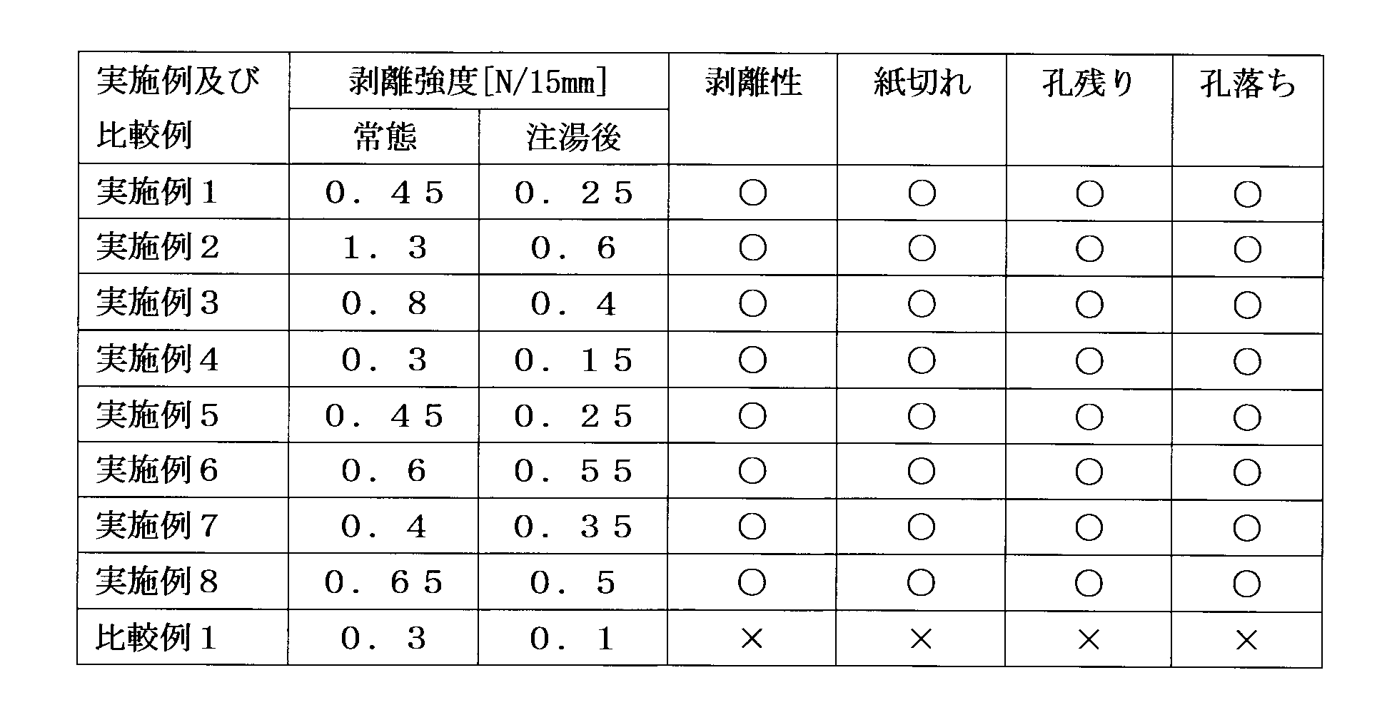
以下、図30~図35を参照して、第4の実施形態に係る容器の蓋材を説明する。
10が剥離しにくくなることはなく、ユーザは問題なく湯切り孔73を形成することができる。したがって、上述した見当合わせはほぼ不要となり、製造効率を著しく向上させることができる。
表面層81の材料として坪量が105g/m2の紙基材を、中間層82の材料として厚み12μmのPETフィルム(商品名E5100:東洋紡績(株)製)を準備した。次に、エクストルージョンラミネート法により接合層83となるLDPEを320℃で押出し、表面層81と中間層82とを一体に接合した。接合層83と接合される中間層82の第1の面82Aは、コロナ処理の施されていない側の面とした。さらに中間層の第2の面82Bにポリスチレン系樹脂を含む材料をエクストルージョンラミネート法により280℃で押出し、易剥離層84を形成して積層品を得た。続いて、この積層品に対して表面層81側からハーフカットを施して部分剥離用ハーフカット72を形成し、易剥離層84側から湯切り孔用ハーフカット77を形成して湯切り孔形成部78を設けた。最後に積層品に抜き加工を施して略矩形の蓋材を作製した。
中間層82の材料として片面にコロナ処理が施された厚み12μmのPETフィルム(商品名FE2001:フタムラ化学(株)製)を用いた。第1の面82Aは、コロナ処理の施されていない側の面とした。後述するように当該材料の第1の面82Aの濡れ性が高めであったため、接合層83となるLDPEを300℃で押し出して表面層81と中間層82とを接合した。それ以外は実施例1と同様の手順で蓋材を作製した。
中間層82の材料として片面にコロナ処理が施された厚み20μmのOPPフィルム(商品名FOR:フタムラ化学(株)製)を用いた。第1の面82Aは、コロナ処理の施されていない側の面とした。それ以外は実施例1と同様の手順で蓋材を作製した。
中間層82の材料として片面にコロナ処理が施された厚み12μmのPETフィルム(商品名エンブレット(登録商標)PET:ユニチカ(株)製)を用いた。第1の面82Aは、コロナ処理の施されていない側の面とした。それ以外は実施例1と同様の手順で蓋材を作製した。
中間層82の材料として片面にコロナ処理が施された厚み12μmのPETフィルム(商品名テトロン(登録商標)PC:帝人デュポンフィルム(株)製)を用いた。第1の面82Aは、コロナ処理の施されていない側の面とした。それ以外は実施例1と同様の手順で蓋材を作製した。
蓋材製造前の中間層82の材料において、第1の面82Aとなる面の濡れ性を測定した。測定には濡れ張力試験用混合液(和光純薬工業(株)製)を用い、JIS-K6768に従って測定を行った。
加熱されていない状態(すなわち、測定時の室温と同程度の温度)の各例の蓋材について、部分剥離用ハーフカット72に囲まれた剥離領域内の表面層81を除去するときの中間層82と接合層83との剥離強度を測定した。測定には引張・圧縮試験機(商品名テンシロンRTF-1250:(株)エー・アンド・デイ製)を用い、JIS-Z1707に従って測定を行った。各例について5つの蓋材を用意し、5回の測定の平均値を測定値とした。

以下、図36~図44を参照して、第5の実施形態に係る容器の蓋材を説明する。
坪量84.9/m2の片面アート紙の裏面に、グラビア印刷機を利用し、ポーシェル版40μ版にて目止めコート剤を塗布し、ヘリオ版70Lにて離型剤を塗布して、易剥離層93付きの上シート91とした。
2)目止め剤:ポリアミド樹脂(花王(株)製:レオマイド-2110PL)とニトロセルロース(旭化成(株)製:1/8H)を溶剤に溶解・分散させたワニス、
3)離型剤:ポリアミド樹脂(花王(株)製:レオマイド-2110PL)とニトロセルロース(旭化成(株)製:1/8H)及びポリエチレンワックスを溶剤に溶解・分散させたワニス、
4)PETフィルム:片面コロナ処理PETフィルム(東洋紡(株)製:E5100(厚さ12μm))、
5)アルミ箔:軟質アルミ(住友アルミ(株)製(厚さ7μm))、
6)低密度ポリエチレン樹脂:住友化学(株)製:L2340E)、及び、
5)シーラント:
1層目:EMAA「N1108C」(三井・デュポン ポリケミカル(株)製(厚さ10μm))、及び
2層目:イージーピールシーラント(三井デュポン ポリケミカル(株)製:VN503(厚さ10μm))、
次に、加工機として、イズミ産業(株)製のロータリーダイカッターを使用して、第1ユニットにてシーラント面から易剥離層までの深さの切込み線で湯切り孔用ハーフカット95を形成し、第2ユニットにて紙面から易剥離層までの深さの切込み線で部分剥離用ハーフカット94を形成し、更に製品の外周縁の抜き加工を行ない、蓋材90を得た。
図37に示すように、部分剥離用ハーフカット94を角の丸い矩形状とし、その内部を剥離領域として設定した。その上で、易剥離領域を、剥離領域を超えて広く設けた。易剥離領域の形状は部分剥離用ハーフカット94で囲まれた剥離領域と相似形である。なお、剥離領域の内部に9カ所の湯切り孔用ハーフカット95を閉曲線状に設け、その内部に剥離剤を塗布していない部位(剥離剤非塗布部)を設けた。剥離剤非塗布部は、湯切り孔用ハーフカット95で囲まれた部位よりわずかに小さく設けられている。また、目止め剤の塗布形状は易剥離領域の形状と同一である。
図38に示すように、易剥離領域の形状を囲む線の一部を部分剥離用ハーフカット94の一部と平行にしたが、相似形とはしなかった。その他は実施例1と同様である。
図39に示すように、易剥離領域を、蓋材を横断する直線とこの蓋材の周縁とで囲まれた領域とした。前記直線は部分剥離用ハーフカット94の一部と平行である。その他は実施例1と同様である。
図40に示すように、易剥離領域を円形とした。その他は実施例1と同様である。
図41に示すように、部分剥離用ハーフカット94を、円の周に沿ってジグザグに屈折した折り曲げ線とした。なお、易剥離領域は実施例1と同様の形状である。また、その他も実施例1と同様である。
図42に示すように、目止め層の塗布領域を、蓋材を横断する直線とこの蓋材の周縁とで囲まれた領域とした。その他は実施例1と同様である。
図43に示すように、易剥離領域を剥離領域と一致させた。すなわち、両者は同一形状で、かつ、位置も同じである。その他は実施例1と同様である。
図44に示すように、易剥離領域を剥離領域と一致させた。すなわち、両者は同一形状で、かつ、位置も同じである。その他は実施例5と同様である。

ここで、上述した各実施形態及びその変形形態に係る蓋材で実施可能な、ハーフカットの位置と部分的に画成される剥離領域との位置関係を図46A~46Cを用いて説明する。なお、符号は図1に用いたものを再度用いる。
本発明に係る容器の蓋を用いれば、ユーザは簡単に且つ確実に液体排出孔(湯切り孔など)をその蓋に出現させることができる。このため、この蓋を湯熱により調理する即席食品の容器などに好適に適用できる。
Claims (16)
- 容器本体の開口部の縁に沿って形成されたフランジに剥離可能に密着して被せる蓋材において、
前記フランジの外形と略同等の大きさを有し、前記開口部及び前記フランジを一体に覆うシート状の蓋本体と、
前記フランジの外側に位置するように前記蓋本体に一体に延設され且つ当該蓋本体を前記開口部から分離するときに使用する第1のプルタブと、
前記蓋本体に一体に延設され且つ当該容器本体から液体を排出させる排出孔を当該蓋本体に出現させるときに使用する第2のプルタブと、を備え、
前記蓋本体、前記第1のプルタブ、及び前記第2のプルタブは、少なくとも、下面を前記フランジに剥離可能に密着させる下シートと、この下シートの上面に積層され且つ上面を当該蓋本体の表面とする上シートとを備えた積層体で構成され、
前記第2のプルタブの根本部分を横断する両側のそれぞれに位置する前記下シートの外縁の2点を結ぶように前記下シートの下面から当該下シートを貫通する第1のハーフカットが形成され、
この第1のハーフカットを開始線として前記蓋本体の面上の内方に向かって延びる部分的な領域に、前記下シートの下面から当該下シートを貫通するように、前記容器本体内の液体の複数の排出孔にそれぞれ対応した所望形状を有し且つ当該領域内で所望の配列を有する複数の排出孔用ハーフカットが形成され、
前記第2のプルタブに対する引き剥がし動作により、前記排出孔用ハーフカットが付された前記下シートの部分を前記上シートの前記部分的な領域の部分に付着させた状態で、当該上シートの当該部分的な領域の部分を前記下シートから剥離可能に構成した、ことを特徴とする蓋材。 - 請求項1に記載の蓋材において、
前記蓋本体の面上にて前記第2のプルタブから前記下シートの外縁上の前記2点よりもそれぞれ遠い前記上シートの外縁上の2つの位置、又は、前記蓋本体の面上にて前記下シートの外縁上の前記2点と一致する前記上シートの外縁上の2つの位置を2つの起点とし、この2つの起点からそれぞれ前記蓋本体の面上の内方に向かって延びて相互に合流し又は一部、切残しを設けた状態で略合流して前記部分的な領域を当該蓋本体に画成するように前記上シートの上面から当該上シートを貫通する第2のハーフカットが形成されている、ことを特徴とする蓋体。 - 請求項1に記載の蓋材において、
前記上シート及び前記下シートの間であって前記複数の排出孔用ハーフカットのそれぞれが囲む部分の少なくとも一部を除いて、前記部分的な領域の部分を含め、当該部分的な領域の周辺まで広げて塗布した剥離剤から成る易剥離層を設け、この易剥離層により前記上シートの前記部分的な領域の部分を前記下シートから部分的に剥離可能に構成したことを特徴とする蓋材。 - 請求項3に記載の蓋材において、
前記上シートは、当該蓋材の表面を成す紙層と、この紙層の前記容器本体側の面に接合される目止め層とを含む積層体であり、
前記易剥離層は、前記目止め層を介して前記紙層に積層されていることを特徴とする蓋材。 - 請求項3または請求項4に記載の蓋材において、
前記複数の排出孔用ハーフカットは、当該蓋材の平面視において一部の周縁を切り残した形状のハーフカットを含むことを特徴とする蓋材。 - 請求項1に記載の蓋材において、
前記上シートは前記下シートとの間の界面剥離により当該下シートから全面で剥離可能に構成されており、
前記上シートと前記下シートとの間の両界面のうち、一方のシートの界面はプラスチック材による界面であり、他方のシートの界面はポリオレフィン系の接着性樹脂による界面であることを特徴とする蓋材。 - 請求項6に記載の蓋材において、
前記プラスチック材は二軸延伸フィルムであり、
前記二軸延伸フィルムの前記接着性樹脂との界面に、剥離強度を高めるためのコーティング層が積層されている蓋材。 - 請求項6に記載の蓋材において、
前記下シートにアルミニウム箔が含まれており、そのアルミニウム箔の厚さが5μm以上且つ12μm以下であることを特徴とする蓋材。 - 請求項1および請求項6乃至8の何れか一項に記載の蓋材において、
前記上シートは、紙またはプラスチックを含んで形成された表面層と、ポリオレフィン系プラスチックからなり、当該表面層の前記容器本体側の面に接合される接合層とを含む積層体であり、
前記下シートは、前記接合層を介して前記表面層の前記容器本体側の面に接合される、プラスチック材からなる中間層と、この中間層の前記容器本体側の面に接合されたイージーピール層とを含む積層体であり、
前記中間層の前記接合層に当接する面は、JIS-K6768の測定方法によって測定された40ダイン以下の濡れ性を有する、ことを特徴とする蓋材。 - 請求項9に記載の蓋材において、
前記接合層と前記中間層との間の剥離強度が、0℃以上30℃以下の温度範囲において0.1N/15mm以上1.0N/15mm以下であることを特徴とする請求項11に記載の蓋材。 - 請求項1および請求項6乃至請求項8の何れか一項に記載の蓋材において、
前記複数の排出孔用ハーフカットはそれぞれ、当該蓋材の平面視において縦横の何れか一方の幅が他方の幅よりも長い細長形状に形成され、且つ、前記中心点と前記第2のプルタブのタブ幅方向の中心位置とを結ぶ線分に対して斜めに形成されていることを特徴とする蓋材。 - 請求項1および請求項6乃至請求項8の何れか一項に記載の蓋材において、
前記複数の排出孔用ハーフカットはそれぞれ、当該蓋材の平面視において前記中心点と前記第2のプルタブのタブ幅方向の中心位置とを結ぶ線分に対してその線分の左右方向に湾曲し且つその左右の湾曲した形状が当該線分に対して線対称であることを特徴とする蓋材。 - 請求項1に記載の蓋材において、
前記複数の排出孔のそれぞれは、その縦横の幅を有する矩形の開口であって、その幅広の寸法をaとし、その幅狭の寸法をbとした場合、2mm≦b≦a≦10mmの関係が成立し、相互に隣接する排出孔同士の間隔が1mm以上b/2以下であることを特徴とする蓋材。 - 請求項13に記載の蓋材において、
前記複数の排出孔のそれぞれは、当該複数の排出孔の開口領域の重心の位置が直交する座標上に配置されていることを特徴とする蓋材。 - 請求項13または請求項14に記載の蓋材において、
前記幅狭の寸法bが、前記内容物である麺の太さの4倍以内であることを特徴とする蓋材。 - 請求項3に記載の蓋材において、
前記第2のハーフカットは前記起点間の幅よりも前記中心点の方に延びるにつれて広がる幅広の部分を有するハーフカットである、ことを特徴とする蓋材。
Priority Applications (2)
| Application Number | Priority Date | Filing Date | Title |
|---|---|---|---|
| CN201080003432.8A CN102438916B (zh) | 2010-07-12 | 2010-12-01 | 具备液体排出孔的盖材 |
| JP2012524399A JP6239234B2 (ja) | 2010-07-12 | 2010-12-01 | 液体排出孔を備えた蓋材 |
Applications Claiming Priority (10)
| Application Number | Priority Date | Filing Date | Title |
|---|---|---|---|
| JP2010-157570 | 2010-07-12 | ||
| JP2010157570 | 2010-07-12 | ||
| JP2010166221 | 2010-07-23 | ||
| JP2010-166221 | 2010-07-23 | ||
| JP2010-198238 | 2010-09-03 | ||
| JP2010198238 | 2010-09-03 | ||
| JP2010-221994 | 2010-09-30 | ||
| JP2010222084 | 2010-09-30 | ||
| JP2010221994 | 2010-09-30 | ||
| JP2010-222084 | 2010-09-30 |
Publications (1)
| Publication Number | Publication Date |
|---|---|
| WO2012008064A1 true WO2012008064A1 (ja) | 2012-01-19 |
Family
ID=45469084
Family Applications (1)
| Application Number | Title | Priority Date | Filing Date |
|---|---|---|---|
| PCT/JP2010/071516 WO2012008064A1 (ja) | 2010-07-12 | 2010-12-01 | 液体排出孔を備えた蓋材 |
Country Status (3)
| Country | Link |
|---|---|
| JP (1) | JP6239234B2 (ja) |
| CN (1) | CN102438916B (ja) |
| WO (1) | WO2012008064A1 (ja) |
Cited By (12)
| Publication number | Priority date | Publication date | Assignee | Title |
|---|---|---|---|---|
| JP2013028374A (ja) * | 2011-07-29 | 2013-02-07 | Showa Aluminum Kan Kk | 飲料容器 |
| JP2013189244A (ja) * | 2012-02-14 | 2013-09-26 | Toppan Printing Co Ltd | 蓋材 |
| JP2014125263A (ja) * | 2012-12-27 | 2014-07-07 | Kyodo Printing Co Ltd | 蓋材 |
| WO2015123629A1 (en) * | 2014-02-17 | 2015-08-20 | Sonoco Development, Inc. | Container having self-contained heater material |
| JP2015189490A (ja) * | 2014-03-28 | 2015-11-02 | 共同印刷株式会社 | 剥離部付き蓋材の製造方法 |
| EP3120999A1 (en) * | 2015-07-21 | 2017-01-25 | Sonoco Development, Inc. | Laminate structure with access openings |
| JP2017039494A (ja) * | 2015-08-17 | 2017-02-23 | 凸版印刷株式会社 | 包装材料及びこれを用いた包装容器 |
| JP2017178369A (ja) * | 2016-03-30 | 2017-10-05 | 凸版印刷株式会社 | 容器 |
| US10549899B2 (en) | 2015-04-17 | 2020-02-04 | Sonoco Development, Inc. | Retortable self-heating food container with air access structure |
| KR200493834Y1 (ko) * | 2020-10-05 | 2021-06-10 | 소윤섭 | 음료용기용 리드지 |
| JP2022090063A (ja) * | 2016-02-29 | 2022-06-16 | 大日本印刷株式会社 | 剥離可能積層体 |
| JP2023093245A (ja) * | 2021-12-22 | 2023-07-04 | 株式会社エフピコ | 包装容器 |
Families Citing this family (4)
| Publication number | Priority date | Publication date | Assignee | Title |
|---|---|---|---|---|
| JP6119038B2 (ja) * | 2012-10-26 | 2017-04-26 | 株式会社フジシール | 包装容器 |
| CN106660686A (zh) * | 2014-07-23 | 2017-05-10 | 凸版印刷株式会社 | 盖体 |
| KR101960695B1 (ko) * | 2018-05-30 | 2019-03-20 | 한국씨씨엘레이블 주식회사 | 컵라면 용기의 물 배출 기능을 가진 뚜껑 및 그 제조 방법 |
| CN113337195B (zh) * | 2021-05-31 | 2022-02-22 | 石家庄市海燕包装材料有限公司 | 塑料用离型油、干拌速食碗盖的加工工艺及干拌速食碗盖 |
Citations (2)
| Publication number | Priority date | Publication date | Assignee | Title |
|---|---|---|---|---|
| JP2002096879A (ja) * | 2000-09-22 | 2002-04-02 | Dainippon Printing Co Ltd | 湯切り孔付き蓋材 |
| JP2007131321A (ja) * | 2005-11-10 | 2007-05-31 | Toppan Printing Co Ltd | 湯切り機能をもつ蓋材 |
Family Cites Families (8)
| Publication number | Priority date | Publication date | Assignee | Title |
|---|---|---|---|---|
| JP2000219278A (ja) * | 1999-01-27 | 2000-08-08 | Toppan Printing Co Ltd | 湯切り口付剥離性蓋材 |
| JP4724977B2 (ja) * | 2001-08-02 | 2011-07-13 | 大日本印刷株式会社 | 湯切り用蓋材 |
| JP4231300B2 (ja) * | 2002-06-03 | 2009-02-25 | 大日本印刷株式会社 | シート状蓋体 |
| JP4369713B2 (ja) * | 2003-09-05 | 2009-11-25 | 共同印刷株式会社 | 湯切り蓋材 |
| JP2005104514A (ja) * | 2003-09-30 | 2005-04-21 | Toppan Printing Co Ltd | 排湯機能を有する蓋材 |
| JP4611814B2 (ja) * | 2005-06-16 | 2011-01-12 | 東洋インキ製造株式会社 | 湯切付即席食品容器蓋材用ワニス |
| JP4750501B2 (ja) * | 2005-08-04 | 2011-08-17 | 共同印刷株式会社 | 液体通過孔を形成可能な蓋材及びそれを用いた容器 |
| JP5062610B2 (ja) * | 2006-05-30 | 2012-10-31 | 共同印刷株式会社 | 液体通過孔を形成可能な蓋材及びそれを用いた容器 |
-
2010
- 2010-12-01 JP JP2012524399A patent/JP6239234B2/ja active Active
- 2010-12-01 CN CN201080003432.8A patent/CN102438916B/zh active Active
- 2010-12-01 WO PCT/JP2010/071516 patent/WO2012008064A1/ja active Application Filing
Patent Citations (2)
| Publication number | Priority date | Publication date | Assignee | Title |
|---|---|---|---|---|
| JP2002096879A (ja) * | 2000-09-22 | 2002-04-02 | Dainippon Printing Co Ltd | 湯切り孔付き蓋材 |
| JP2007131321A (ja) * | 2005-11-10 | 2007-05-31 | Toppan Printing Co Ltd | 湯切り機能をもつ蓋材 |
Cited By (18)
| Publication number | Priority date | Publication date | Assignee | Title |
|---|---|---|---|---|
| JP2013028374A (ja) * | 2011-07-29 | 2013-02-07 | Showa Aluminum Kan Kk | 飲料容器 |
| JP2013189244A (ja) * | 2012-02-14 | 2013-09-26 | Toppan Printing Co Ltd | 蓋材 |
| JP2014125263A (ja) * | 2012-12-27 | 2014-07-07 | Kyodo Printing Co Ltd | 蓋材 |
| WO2015123629A1 (en) * | 2014-02-17 | 2015-08-20 | Sonoco Development, Inc. | Container having self-contained heater material |
| US9278796B2 (en) | 2014-02-17 | 2016-03-08 | Sonoco Development, Inc. | Container having self-contained heater material |
| JP2015189490A (ja) * | 2014-03-28 | 2015-11-02 | 共同印刷株式会社 | 剥離部付き蓋材の製造方法 |
| US10549899B2 (en) | 2015-04-17 | 2020-02-04 | Sonoco Development, Inc. | Retortable self-heating food container with air access structure |
| US10369764B2 (en) | 2015-07-21 | 2019-08-06 | Sonoco Development, Inc. | Laminate structure with access openings |
| US9782946B2 (en) | 2015-07-21 | 2017-10-10 | Sonoco Development, Inc. | Laminate structure with access openings |
| US10052839B2 (en) | 2015-07-21 | 2018-08-21 | Sonoco Development, Inc. | Laminate structure with access openings |
| EP3385071A1 (en) * | 2015-07-21 | 2018-10-10 | Sonoco Development, Inc. | Laminate structure with access openings |
| EP3120999A1 (en) * | 2015-07-21 | 2017-01-25 | Sonoco Development, Inc. | Laminate structure with access openings |
| JP2017039494A (ja) * | 2015-08-17 | 2017-02-23 | 凸版印刷株式会社 | 包装材料及びこれを用いた包装容器 |
| JP2022090063A (ja) * | 2016-02-29 | 2022-06-16 | 大日本印刷株式会社 | 剥離可能積層体 |
| JP7363957B2 (ja) | 2016-02-29 | 2023-10-18 | 大日本印刷株式会社 | 剥離可能積層体 |
| JP2017178369A (ja) * | 2016-03-30 | 2017-10-05 | 凸版印刷株式会社 | 容器 |
| KR200493834Y1 (ko) * | 2020-10-05 | 2021-06-10 | 소윤섭 | 음료용기용 리드지 |
| JP2023093245A (ja) * | 2021-12-22 | 2023-07-04 | 株式会社エフピコ | 包装容器 |
Also Published As
| Publication number | Publication date |
|---|---|
| JP6239234B2 (ja) | 2017-11-29 |
| JPWO2012008064A1 (ja) | 2013-09-05 |
| CN102438916A (zh) | 2012-05-02 |
| CN102438916B (zh) | 2014-07-16 |
Similar Documents
| Publication | Publication Date | Title |
|---|---|---|
| JP6239234B2 (ja) | 液体排出孔を備えた蓋材 | |
| US10071841B2 (en) | Scored package | |
| JP5736878B2 (ja) | 蓋材 | |
| JP4750502B2 (ja) | 液体通過孔を形成可能な蓋材及びそれを用いた容器 | |
| JP5659629B2 (ja) | 包装袋 | |
| JPH11147559A (ja) | 蓋材及びそれを用いた容器 | |
| WO2022264815A1 (ja) | 複合フィルム、蓋材、及び内容物入り蓋付容器 | |
| JP3923645B2 (ja) | 包装袋 | |
| JP5569056B2 (ja) | 蓋材 | |
| JP6478716B2 (ja) | 部分開封用積層体 | |
| JP4074115B2 (ja) | 易開封性包装体 | |
| WO2004106189A1 (ja) | 即席食品用容器及びその容器を使用した即席食品 | |
| JP3867474B2 (ja) | 易開封性複合フィルム及び包装容器 | |
| JP5838604B2 (ja) | 蓋材 | |
| JP2006290438A (ja) | 易開封性深絞り包装体 | |
| JP2013023238A (ja) | 蓋材 | |
| JP4882530B2 (ja) | シュリンク包装容器 | |
| JP7357435B2 (ja) | 易剥離性蓋材 | |
| JP4357897B2 (ja) | シート状蓋体 | |
| JPH10329845A (ja) | 易開口包装袋及びその製造方法 | |
| JP4435515B2 (ja) | 食品容器 | |
| JP2007008494A (ja) | 包材 | |
| JP2014043248A (ja) | 蓋材 | |
| JP6566710B2 (ja) | ホットスポット付蓋材 | |
| JP5915110B2 (ja) | 蓋材 |
Legal Events
| Date | Code | Title | Description |
|---|---|---|---|
| WWE | Wipo information: entry into national phase |
Ref document number: 201080003432.8 Country of ref document: CN |
|
| 121 | Ep: the epo has been informed by wipo that ep was designated in this application |
Ref document number: 10854746 Country of ref document: EP Kind code of ref document: A1 |
|
| NENP | Non-entry into the national phase |
Ref country code: DE |
|
| ENP | Entry into the national phase |
Ref document number: 2012524399 Country of ref document: JP Kind code of ref document: A |
|
| 122 | Ep: pct application non-entry in european phase |
Ref document number: 10854746 Country of ref document: EP Kind code of ref document: A1 |