WO2011145578A1 - 車輪用軸受装置 - Google Patents
車輪用軸受装置 Download PDFInfo
- Publication number
- WO2011145578A1 WO2011145578A1 PCT/JP2011/061234 JP2011061234W WO2011145578A1 WO 2011145578 A1 WO2011145578 A1 WO 2011145578A1 JP 2011061234 W JP2011061234 W JP 2011061234W WO 2011145578 A1 WO2011145578 A1 WO 2011145578A1
- Authority
- WO
- WIPO (PCT)
- Prior art keywords
- bearing device
- wheel
- seal ring
- wheel bearing
- axle tube
- Prior art date
- Legal status (The legal status is an assumption and is not a legal conclusion. Google has not performed a legal analysis and makes no representation as to the accuracy of the status listed.)
- Ceased
Links
Images

Classifications
-
- F—MECHANICAL ENGINEERING; LIGHTING; HEATING; WEAPONS; BLASTING
- F16—ENGINEERING ELEMENTS AND UNITS; GENERAL MEASURES FOR PRODUCING AND MAINTAINING EFFECTIVE FUNCTIONING OF MACHINES OR INSTALLATIONS; THERMAL INSULATION IN GENERAL
- F16C—SHAFTS; FLEXIBLE SHAFTS; ELEMENTS OR CRANKSHAFT MECHANISMS; ROTARY BODIES OTHER THAN GEARING ELEMENTS; BEARINGS
- F16C33/00—Parts of bearings; Special methods for making bearings or parts thereof
- F16C33/72—Sealings
- F16C33/76—Sealings of ball or roller bearings
- F16C33/78—Sealings of ball or roller bearings with a diaphragm, disc, or ring, with or without resilient members
- F16C33/7803—Sealings of ball or roller bearings with a diaphragm, disc, or ring, with or without resilient members suited for particular types of rolling bearings
- F16C33/7813—Sealings of ball or roller bearings with a diaphragm, disc, or ring, with or without resilient members suited for particular types of rolling bearings for tapered roller bearings
-
- B—PERFORMING OPERATIONS; TRANSPORTING
- B60—VEHICLES IN GENERAL
- B60B—VEHICLE WHEELS; CASTORS; AXLES FOR WHEELS OR CASTORS; INCREASING WHEEL ADHESION
- B60B27/00—Hubs
- B60B27/001—Hubs with roller-bearings
-
- B—PERFORMING OPERATIONS; TRANSPORTING
- B60—VEHICLES IN GENERAL
- B60B—VEHICLE WHEELS; CASTORS; AXLES FOR WHEELS OR CASTORS; INCREASING WHEEL ADHESION
- B60B27/00—Hubs
- B60B27/0073—Hubs characterised by sealing means
-
- B—PERFORMING OPERATIONS; TRANSPORTING
- B60—VEHICLES IN GENERAL
- B60B—VEHICLE WHEELS; CASTORS; AXLES FOR WHEELS OR CASTORS; INCREASING WHEEL ADHESION
- B60B27/00—Hubs
- B60B27/0078—Hubs characterised by the fixation of bearings
- B60B27/0084—Hubs characterised by the fixation of bearings caulking to fix inner race
-
- B—PERFORMING OPERATIONS; TRANSPORTING
- B60—VEHICLES IN GENERAL
- B60B—VEHICLE WHEELS; CASTORS; AXLES FOR WHEELS OR CASTORS; INCREASING WHEEL ADHESION
- B60B35/00—Axle units; Parts thereof ; Arrangements for lubrication of axles
- B60B35/12—Torque-transmitting axles
- B60B35/18—Arrangement of bearings
-
- F—MECHANICAL ENGINEERING; LIGHTING; HEATING; WEAPONS; BLASTING
- F16—ENGINEERING ELEMENTS AND UNITS; GENERAL MEASURES FOR PRODUCING AND MAINTAINING EFFECTIVE FUNCTIONING OF MACHINES OR INSTALLATIONS; THERMAL INSULATION IN GENERAL
- F16C—SHAFTS; FLEXIBLE SHAFTS; ELEMENTS OR CRANKSHAFT MECHANISMS; ROTARY BODIES OTHER THAN GEARING ELEMENTS; BEARINGS
- F16C19/00—Bearings with rolling contact, for exclusively rotary movement
- F16C19/22—Bearings with rolling contact, for exclusively rotary movement with bearing rollers essentially of the same size in one or more circular rows, e.g. needle bearings
- F16C19/34—Bearings with rolling contact, for exclusively rotary movement with bearing rollers essentially of the same size in one or more circular rows, e.g. needle bearings for both radial and axial load
- F16C19/38—Bearings with rolling contact, for exclusively rotary movement with bearing rollers essentially of the same size in one or more circular rows, e.g. needle bearings for both radial and axial load with two or more rows of rollers
- F16C19/383—Bearings with rolling contact, for exclusively rotary movement with bearing rollers essentially of the same size in one or more circular rows, e.g. needle bearings for both radial and axial load with two or more rows of rollers with tapered rollers, i.e. rollers having essentially the shape of a truncated cone
- F16C19/385—Bearings with rolling contact, for exclusively rotary movement with bearing rollers essentially of the same size in one or more circular rows, e.g. needle bearings for both radial and axial load with two or more rows of rollers with tapered rollers, i.e. rollers having essentially the shape of a truncated cone with two rows, i.e. double-row tapered roller bearings
- F16C19/386—Bearings with rolling contact, for exclusively rotary movement with bearing rollers essentially of the same size in one or more circular rows, e.g. needle bearings for both radial and axial load with two or more rows of rollers with tapered rollers, i.e. rollers having essentially the shape of a truncated cone with two rows, i.e. double-row tapered roller bearings in O-arrangement
-
- F—MECHANICAL ENGINEERING; LIGHTING; HEATING; WEAPONS; BLASTING
- F16—ENGINEERING ELEMENTS AND UNITS; GENERAL MEASURES FOR PRODUCING AND MAINTAINING EFFECTIVE FUNCTIONING OF MACHINES OR INSTALLATIONS; THERMAL INSULATION IN GENERAL
- F16C—SHAFTS; FLEXIBLE SHAFTS; ELEMENTS OR CRANKSHAFT MECHANISMS; ROTARY BODIES OTHER THAN GEARING ELEMENTS; BEARINGS
- F16C33/00—Parts of bearings; Special methods for making bearings or parts thereof
- F16C33/30—Parts of ball or roller bearings
- F16C33/58—Raceways; Race rings
- F16C33/583—Details of specific parts of races
- F16C33/586—Details of specific parts of races outside the space between the races, e.g. end faces or bore of inner ring
-
- F—MECHANICAL ENGINEERING; LIGHTING; HEATING; WEAPONS; BLASTING
- F16—ENGINEERING ELEMENTS AND UNITS; GENERAL MEASURES FOR PRODUCING AND MAINTAINING EFFECTIVE FUNCTIONING OF MACHINES OR INSTALLATIONS; THERMAL INSULATION IN GENERAL
- F16C—SHAFTS; FLEXIBLE SHAFTS; ELEMENTS OR CRANKSHAFT MECHANISMS; ROTARY BODIES OTHER THAN GEARING ELEMENTS; BEARINGS
- F16C33/00—Parts of bearings; Special methods for making bearings or parts thereof
- F16C33/72—Sealings
- F16C33/76—Sealings of ball or roller bearings
- F16C33/768—Sealings of ball or roller bearings between relatively stationary parts, i.e. static seals
-
- F—MECHANICAL ENGINEERING; LIGHTING; HEATING; WEAPONS; BLASTING
- F16—ENGINEERING ELEMENTS AND UNITS; GENERAL MEASURES FOR PRODUCING AND MAINTAINING EFFECTIVE FUNCTIONING OF MACHINES OR INSTALLATIONS; THERMAL INSULATION IN GENERAL
- F16C—SHAFTS; FLEXIBLE SHAFTS; ELEMENTS OR CRANKSHAFT MECHANISMS; ROTARY BODIES OTHER THAN GEARING ELEMENTS; BEARINGS
- F16C35/00—Rigid support of bearing units; Housings, e.g. caps, covers
- F16C35/04—Rigid support of bearing units; Housings, e.g. caps, covers in the case of ball or roller bearings
- F16C35/06—Mounting or dismounting of ball or roller bearings; Fixing them onto shaft or in housing
- F16C35/067—Fixing them in a housing
-
- B—PERFORMING OPERATIONS; TRANSPORTING
- B60—VEHICLES IN GENERAL
- B60B—VEHICLE WHEELS; CASTORS; AXLES FOR WHEELS OR CASTORS; INCREASING WHEEL ADHESION
- B60B2380/00—Bearings
- B60B2380/10—Type
- B60B2380/14—Roller bearings
-
- B—PERFORMING OPERATIONS; TRANSPORTING
- B60—VEHICLES IN GENERAL
- B60B—VEHICLE WHEELS; CASTORS; AXLES FOR WHEELS OR CASTORS; INCREASING WHEEL ADHESION
- B60B2380/00—Bearings
- B60B2380/70—Arrangements
- B60B2380/73—Double track
-
- B—PERFORMING OPERATIONS; TRANSPORTING
- B60—VEHICLES IN GENERAL
- B60B—VEHICLE WHEELS; CASTORS; AXLES FOR WHEELS OR CASTORS; INCREASING WHEEL ADHESION
- B60B2900/00—Purpose of invention
- B60B2900/20—Avoidance of
- B60B2900/211—Soiling
-
- B—PERFORMING OPERATIONS; TRANSPORTING
- B60—VEHICLES IN GENERAL
- B60B—VEHICLE WHEELS; CASTORS; AXLES FOR WHEELS OR CASTORS; INCREASING WHEEL ADHESION
- B60B2900/00—Purpose of invention
- B60B2900/50—Improvement of
- B60B2900/511—Sealing
- B60B2900/5112—Sealing against dust or dirt
-
- B—PERFORMING OPERATIONS; TRANSPORTING
- B60—VEHICLES IN GENERAL
- B60Y—INDEXING SCHEME RELATING TO ASPECTS CROSS-CUTTING VEHICLE TECHNOLOGY
- B60Y2200/00—Type of vehicle
- B60Y2200/10—Road Vehicles
- B60Y2200/11—Passenger cars; Automobiles
-
- F—MECHANICAL ENGINEERING; LIGHTING; HEATING; WEAPONS; BLASTING
- F16—ENGINEERING ELEMENTS AND UNITS; GENERAL MEASURES FOR PRODUCING AND MAINTAINING EFFECTIVE FUNCTIONING OF MACHINES OR INSTALLATIONS; THERMAL INSULATION IN GENERAL
- F16C—SHAFTS; FLEXIBLE SHAFTS; ELEMENTS OR CRANKSHAFT MECHANISMS; ROTARY BODIES OTHER THAN GEARING ELEMENTS; BEARINGS
- F16C2240/00—Specified values or numerical ranges of parameters; Relations between them
- F16C2240/40—Linear dimensions, e.g. length, radius, thickness, gap
- F16C2240/42—Groove sizes
-
- F—MECHANICAL ENGINEERING; LIGHTING; HEATING; WEAPONS; BLASTING
- F16—ENGINEERING ELEMENTS AND UNITS; GENERAL MEASURES FOR PRODUCING AND MAINTAINING EFFECTIVE FUNCTIONING OF MACHINES OR INSTALLATIONS; THERMAL INSULATION IN GENERAL
- F16C—SHAFTS; FLEXIBLE SHAFTS; ELEMENTS OR CRANKSHAFT MECHANISMS; ROTARY BODIES OTHER THAN GEARING ELEMENTS; BEARINGS
- F16C2326/00—Articles relating to transporting
- F16C2326/01—Parts of vehicles in general
- F16C2326/02—Wheel hubs or castors
Definitions
- the present invention relates to a wheel bearing device for rotatably supporting a wheel of an automobile or the like with respect to a suspension device, and more particularly to a semi-floating type wheel bearing device for supporting a driving wheel with a double row rolling bearing.
- the wheel bearing device is light and compact, and prevents rainwater, dust, etc. and diff oil from leaking.
- the wheel assembly 51 and the double-row rolling bearing 52 are configured as a unit and driven. It is connected to the axis D / S.
- the double row rolling bearing 52 includes an inner member 53, an outer member 54, and double row tapered rollers 55, 55 accommodated between the members 53, 54 so as to roll freely.
- the hub wheel 51 integrally has a wheel attachment flange 56 for attaching the wheel W and the brake rotor B to one end portion of the outer periphery, and a small-diameter step portion 57 extending in the axial direction from the wheel attachment flange 56 is formed.
- a serration 58 is formed on the inner periphery so that the drive shaft D / S is fitted in such a manner that torque can be transmitted.
- the double-row rolling bearing 52 is an outer member in which double-row tapered outer rolling surfaces 54a and 54a are formed on the inner periphery, and a vehicle body mounting flange 54b fixed to the axle tube H is formed on the outer periphery. 54, and a pair of inner rings 60, 60 that are inserted into the outer member 54 and have a tapered inner rolling surface 60a opposed to the double row outer rolling surfaces 54a, 54a on the outer periphery, Double-row tapered rollers 55 and 55 accommodated so as to roll between the rolling surfaces 54a and 60a.
- a pair of inner rings 60, 60 are press-fitted into the small-diameter step portion 57 formed on the outer periphery of the hub wheel 51, and a crimping portion 59 formed by plastically deforming the end portion of the small-diameter step portion 57 radially outwardly, The inner ring 60 is prevented from coming off in the axial direction with respect to the hub ring 51.
- the pair of inner rings 60, 60 are set in a state where the front side end faces are abutted against each other, and constitute a so-called back-to-back type double row tapered roller bearing.
- the cap 61 is press-fitted into the opening of the hub wheel 51.
- the cap 61 is formed into a substantially U-shaped cross section by pressing an austenitic stainless steel plate (JIS standard SUS304 type or the like) or a rust-proof cold rolled steel plate (JIS standard SPCC type or the like).
- the elastic member 61b is elastically deformed and enters the fitting surface to seal the inside in a liquid-tight manner.
- it is possible to completely prevent the diff oil from flowing out, and rainwater, dust, etc. from entering the drive shaft from the outside and entering the def oil. Even if the moment load is applied and elastically deformed, the cap 61 is hardly affected by the elastic deformation of the hub wheel 51 (see, for example, Patent Document 1).
- the present invention has been made in view of such conventional problems, and prevents the intrusion of rainwater, dust, etc. and the leakage of differential oil to enhance the sealing effect and ensure reliability over a long period of time.
- An object is to provide a bearing device.
- the invention according to claim 1 of the present invention is coupled to an axle tube that is supported on the lower surface of a vehicle body through a drive shaft connected to a differential, and is coupled to the drive shaft.
- a hub wheel integrally having a wheel mounting flange for mounting a wheel and having a cylindrical small diameter step portion extending in the axial direction on the outer periphery, and a small diameter step portion of the hub wheel and an opening portion of the axle tube
- a wheel bearing that is fitted between the wheels and rotatably supports the wheel, the wheel bearing being mounted on the outer periphery of the vehicle body mounting flange, and on the inner end of the axle.
- An inner rolling surface opposite to the outer rolling surface is formed.
- An annular groove is formed in a pilot portion of the outer member in a wheel bearing device including a seal mounted in an opening of an annular space formed between a member and an inner member.
- a seal ring made of synthetic rubber is attached and elastically contacted with the axle tube, and a slight gap in the fitting portion between the outer member and the axle tube is blocked.
- the axle tube that is inserted into the drive shaft connected to the differential and is supported on the lower surface of the vehicle body, the hub wheel integrally including the wheel mounting flange, and the opening between the hub wheel and the opening of the axle tube.
- a semi-floating type wheel bearing device having a wheel bearing made up of a double row rolling bearing fitted in a ring, an annular groove is formed in the pilot portion of the outer member, and the annular groove is made of synthetic rubber.
- a seal ring is attached and elastically contacted with the axle tube, and the slight gap between the fitting part between the outer member and the axle tube is cut off, preventing rainwater, dust, etc. and diff oil from leaking. It is possible to provide a wheel bearing device that enhances the stopping effect and ensures reliability over a long period of time.
- the pilot portion of the outer member has a cylindrical portion extending in the axial direction from the vehicle body mounting flange, and a gradually reduced diameter from the cylindrical portion toward the inner end surface. If the fitting portion of the axle tube is formed corresponding to the shape of the pilot portion of the outer member, the assembly of the bearing portion to the axle tube is facilitated and the assembly work is performed. Is simplified.
- the annular groove is formed in the tapered portion of the pilot portion, the assemblability of the bearing portion to the axle tube is improved.
- the seal ring when the inner diameter of the seal ring alone is set smaller than the groove bottom diameter of the annular groove, the seal ring has a shimishi when the seal ring is mounted.
- the seal ring when the bearing portion is assembled to the axle tube, the seal ring can be prevented from being bent and biting into the axle tube.
- a predetermined hardened layer is formed by induction hardening on the outer raceway of the double row of the outer member, and the effective hardened layer depth of this hardened layer is 2-4. If the shortest distance between the annular groove and the outer rolling surface is set to 4.5 mm or more, the annular groove is not affected by heat due to quenching and heat treatment deformation is set. In addition, the strength can be prevented from being lowered due to burnout or the like, and the reliability can be improved.
- the annular groove is formed in a substantially rectangular cross section, and the corner R on the side closer to the outer rolling surface among the corners R of the annular groove is the far corner R. If it is set to be larger than the same corner R, the distance from the outer rolling surface is substantially larger than that in the case of the same corner R, which is advantageous for heat treatment deformation and repeated bending load and the like. The strength when loaded is increased, and the durability can be improved.
- the annular groove is formed in a substantially semicircular cross section and the shape of the groove bottom portion is configured with a single radius of curvature, it is hardly affected by heat due to quenching, Moreover, the strength fall by the notch effect can be suppressed.
- the compression set of the rubber property value of the seal ring is set to 40% or less at 120 ° C. ⁇ 70 hours, and the TR10 value (elongation rate 50%) is set to ⁇ 20 ° C. or less. If so, the strain recovery is good even in the low temperature region, and the desired sealing effect can be maintained.
- the hue of the seal ring is set to a warm color, it is possible to prevent forgetting to attach the seal ring at the time of assembly or overlooking when confirming the installation.
- the assembly work can be simplified.
- the seal ring As a result, the bearing portion can be smoothly fitted to the axle tube without being bent even when the seal ring contacts the axle tube during assembly.
- the seal ring is selected from hydrogenated acrylonitrile-butadiene rubber, ethylene / propylene rubber, polyacrylic rubber, fluorine rubber, and silicon rubber, heat resistance, It has excellent chemical resistance and can improve durability.
- a wheel bearing device integrally includes an axle tube that is inserted into a drive shaft connected to a differential and supported on the lower surface of a vehicle body, and a wheel mounting flange that is coupled to the drive shaft and attaches a wheel.
- a hub wheel having a cylindrical small-diameter stepped portion extending in the axial direction on the outer periphery, and fitted between the small-diameter stepped portion of the hub wheel and the opening of the axle tube to rotate the wheel.
- a wheel bearing that is freely supported, and this wheel bearing is integrally formed with a vehicle body mounting flange on the outer periphery for mounting to the axle tube and a pilot portion that is fitted inside the axle tube at the inner end.
- An outer member in which a double row outer rolling surface is integrally formed on the inner periphery, and an inner rolling that is press-fitted into a small diameter step portion of the hub wheel and faces the outer rolling surface of the double row Inward consisting of at least one inner ring with a surface formed Material, a double row rolling element housed between the rolling surfaces of the inner member and the outer member via a cage, and between the outer member and the inner member.
- a wheel bearing device provided with a seal attached to an opening of an annular space to be formed, an annular groove is formed in a pilot portion of the outer member, and a seal ring made of synthetic rubber is attached to the annular groove.
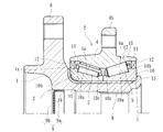
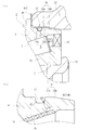
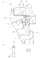
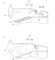
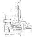
- FIG. 1 It is a longitudinal cross-sectional view of the suspension periphery which shows one Embodiment of the wheel bearing apparatus which concerns on this invention. It is a longitudinal cross-sectional view which shows the wheel bearing apparatus of FIG. (A) is the principal part enlarged view of FIG. 2, (b) is the elements on larger scale of (a). (A) is a principal part enlarged view which shows the modification of Fig.3 (a), (b) is sectional drawing which shows the seal ring single-piece
- An axle tube that is inserted into the drive shaft connected to the differential and is supported on the lower surface of the vehicle body, and a wheel mounting flange that is connected to the drive shaft via serrations and attaches a wheel to the outer periphery.
- a hub wheel formed with a small-diameter step portion extending in the axial direction, and a wheel bearing that is fitted between the small-diameter step portion of the hub wheel and the opening of the axle tube and rotatably supports the wheel.
- This wheel bearing has a vehicle body mounting flange for mounting to the axle tube on the outer periphery, and a pilot portion fitted into the axle tube on the inner side end portion, and a double row on the inner periphery.
- An outer member formed integrally with the outer rolling surface, a pair of inner rings formed with an inner rolling surface facing the outer rolling surface of the double row on the outer periphery, the pair of inner rings and the outer Rollable via a cage between both rolling surfaces of the member
- a semi-floating type in which the inner ring is fixed in the axial direction with respect to the hub ring by a crimped portion formed by fitting the inner ring of the bearing and plastically deforming the end of the small diameter step portion radially outward.
- the pilot portion of the outer member includes a cylindrical portion that extends in the axial direction from the vehicle body mounting flange, and a tapered portion that gradually decreases in diameter from the cylindrical portion toward the inner end surface.
- the fitting portion of the axle tube is formed corresponding to the shape of the pilot portion of the outer member, and an annular groove having a substantially rectangular cross section is formed in the tapered portion of the pilot portion, and the annular groove is made of synthetic rubber.
- FIG. 1 is a longitudinal sectional view around a suspension showing an embodiment of a wheel bearing device according to the present invention
- FIG. 2 is a longitudinal sectional view showing the wheel bearing device of FIG. 1
- FIG. 2B is an enlarged view of a part of FIG. 2A
- FIG. 4A is an enlarged view of a main part showing a modification of FIG. 3A
- FIG. FIG. 5A is a partially enlarged view of FIG. 4
- FIG. 5B is a partially enlarged view showing a modification of FIG. 4A.
- the side closer to the outer side of the vehicle when assembled to the vehicle is referred to as the outer side (left side in FIG. 1)
- the side closer to the center is referred to as the inner side (right side in FIG. 1).
- This semi-floating type wheel bearing device has a hub wheel 1 and a double row rolling bearing 2 as a unit, and is connected to a drive shaft D / S.
- the double row rolling bearing 2 includes an inner member 3, an outer member 4, and double row rolling elements (conical rollers) 5, 5 accommodated between both members 3, 4 so as to be freely rollable.
- the inner member 3 refers to the hub wheel 1 and a pair of inner rings 10 and 10 press-fitted into the hub wheel 1.
- the hub wheel 1 integrally has a wheel mounting flange 6 for mounting the wheel W and the brake rotor B at the outer end, and a cylindrical small-diameter step 7 extending axially from the wheel mounting flange 6 on the outer periphery.
- a serration (or spline) 8 is formed on the inner periphery.
- the drive shaft D / S is fitted and inserted into the hub wheel 1 via the serrations 8, and the hub wheel 1 and the drive shaft D / S are coupled to each other so as to be able to transmit torque and be detachable.
- the double-row rolling bearing 2 has a double-row tapered outer rolling surface 4a, 4a integrally formed on the inner periphery and is fixed to the axle tube 14 on the outer periphery.
- a pair of inner rings 10 and 10 formed with a double row rolling elements 5 and 5 accommodated between both rolling surfaces 4a and 10a, and the double row rolling elements 5 and 5 are held in a freely rollable manner.
- the pair of inner rings 10 and 10 are formed with a large collar 10b for guiding the rolling element 5 to the large diameter side of the inner rolling surface 10a and a small collar 10c for preventing the rolling element 5 from dropping off on the small diameter side. ing. And it sets in the state where the front side end surfaces of a pair of inner rings 10 and 10 were abutted, and it constitutes what is called a back alignment type double row tapered roller bearing.
- seals 12 and 12 are attached to the opening of the annular space formed between the outer member 4 and the inner ring 10, leakage of the lubricating grease sealed inside the bearing to the outside, rainwater and Dust and the like are prevented from entering the bearing. Further, the inner seal 12 prevents the differential oil from entering the bearing through the serration 8 of the hub wheel 1.
- a pair of inner rings 10 and 10 is press-fitted into the small-diameter step portion 7 of the hub wheel 1 through a predetermined shimiro, and an end portion of the small-diameter step portion 7 is plastically deformed outward in the radial direction. 13, the inner rings 10 and 10 are fixed in the axial direction with respect to the hub wheel 1 in a state where a predetermined bearing preload is applied.
- a second generation self-retain structure it is not necessary to tightly tighten the inner ring with a nut or the like to control the preload amount as in the prior art.
- the number of parts can be greatly reduced, and combined with improved embedding, achieves low cost, light weight and compactness. can do.
- the hub wheel 1 is formed of medium and high carbon steel containing 0.40 to 0.80 wt% of carbon such as S53C, and the surface is formed by induction quenching from the shoulder portion 1a where the double row rolling bearing 2 is abutted to the small diameter step portion 7. Hardening is performed in the range of 50 to 64 HRC (indicated by cross hatching in the figure).
- the caulking portion 13 is an unquenched portion having a material surface hardness of 25 HRC or less after forging. As a result, the durability is improved and the workability when plastically deforming the crimped portion 13 is improved, and microcracks and the like are prevented to improve the reliability of the quality.
- the outer member 4 is made of medium and high carbon steel containing 0.40 to 0.80 wt% of carbon such as S53C, and at least the double row outer rolling surfaces 4a and 4a are formed by induction hardening.
- the surface hardness is set in the range of 58 to 64 HRC.
- the inner ring 10 and the rolling element 5 are made of high carbon chrome bearing steel such as SUJ2, and are hardened in the range of 60 to 64 HRC up to the core by quenching.
- the double row tapered roller bearing which used the rolling elements 5 and 5 as a tapered roller was illustrated here, not only this but the double row angular contact ball bearing which uses the ball for the rolling element may be sufficient.
- the wheel bearing apparatus comprised by the 2nd generation structure where a pair of inner ring
- the cap 9 is press-fitted into the opening at the outer end of the hub wheel 1.
- the cap 9 is formed by pressing an austenitic stainless steel plate (JIS standard SUS304 type or the like) or a rust-proof cold rolled steel plate (JIS standard SPCC type or the like) into a substantially U-shaped cross section.
- the elastic member 9b is elastically deformed and enters the fitting surface to seal the inside in a liquid-tight manner. Accordingly, it is possible to prevent the differential oil from flowing out and rainwater, dust, etc. from the outside to enter the drive shaft and enter the differential oil.
- the pilot portion 15 of the outer member 4 includes a cylindrical portion 15a extending in the axial direction from the vehicle body mounting flange 4b and an end surface on the inner side from the cylindrical portion 15a.
- the taper portion 15b gradually decreases in diameter.
- the shape of the fitting portion 16 of the axle tube 14 is also gradually increased from the cylindrical portion 16a to the inner side from the cylindrical portion 16a.
- the double row rolling bearing 2 is fitted to the axle tube 14 with the tapered portion 16b having a reduced diameter and the brake cover B / C sandwiched therebetween. Thereby, the assembly of the bearing portion to the axle tube 14 is facilitated, the assembling work is simplified, and the airtightness of the fitting portion between the bearing portion and the axle tube 14 is increased.
- annular groove 17 having a rectangular cross section is formed in the cylindrical portion 15 a of the pilot portion 15, and a seal ring 18 having a circular cross section is attached to the annular groove 17.
- the seal ring 18 is made of a synthetic rubber such as NBR, is elastically contacted with the axle tube 14, and blocks a slight gap at the fitting portion between the outer member 4 and the axle tube 14. Accordingly, it is possible to provide a wheel bearing device that prevents rainwater and dust from entering and leaks differential oil, enhances the sealing effect, and ensures reliability over a long period of time.
- the material of the seal ring 18 includes, for example, HNBR (hydrogenated acrylonitrile-butadiene rubber), EPDM (ethylene / propylene rubber), ACM (polyacrylic rubber), etc., which have excellent heat resistance.
- HNBR hydrogenated acrylonitrile-butadiene rubber
- EPDM ethylene / propylene rubber
- ACM polyacrylic rubber
- FKM fluoro rubber
- silicon rubber or the like can be exemplified.
- ACM, FKM, EPDM, and silicon rubber which are excellent in heat resistance and chemical resistance, are preferred for applications that contact this type of differential oil.
- This seal ring 18 has a compression set of rubber physical properties of 40% or less at 120 ° C. ⁇ 70 hours and a TR10 value (elongation rate 50%) of ⁇ 20 ° C. or less.
- the TR10 value indicates the temperature at which the strain applied in advance is recovered by 10%, and the vicinity of this value is empirically used as the low temperature limit value of the rubber material.
- the inner diameter of the seal ring 18 before mounting is set smaller than the groove bottom diameter of the annular groove 17.
- a method may be considered in which an annular groove is formed in the axle tube and a seal ring is attached to the annular groove in advance. In this case, the seal ring contacts the outer member when the bearing portion is assembled to the axle tube. Then, it is not preferable because it may fall out of the annular groove and be bitten.
- a predetermined hardened layer 19 is formed by induction hardening on the outer rolling surface 4a of the double row of the outer member 4 (indicated by cross hatching in the figure),
- the effective hardened layer depth of the hardened layer 19 is set in the range of 2 to 4.5 mm.
- the annular groove 17 is arrange
- the corner R of the annular groove 17 closer to the outer rolling surface 4a here, the inner corner R (R2) is larger than the outer corner R (R1) (R2> R1). Is set.
- the hue of the seal ring 18 is set to a warm color such as red, yellow, orange, yellow-green, or the like. Thereby, it is possible to prevent forgetting to attach the seal ring 18 at the time of assembling and oversight when confirming the mounting, and to simplify the assembling work.
- the same grease as the grease enclosed in the bearing is applied to the seal ring 18 in advance, and the seal ring 18 is mounted with the grease adhered to the surface.
- the mounting property of the seal ring 18 is improved, and even when the seal ring 18 contacts the axle tube 14 during assembly, the bearing portion can be smoothly fitted to the axle tube 14 without bending.
- Fig. 4 (a) shows a modification.
- the pilot portion 21 of the outer member 20 includes a cylindrical portion 21a that extends in the axial direction from the vehicle body mounting flange 4b, and a tapered portion 21b that gradually decreases in diameter from the cylindrical portion 21a toward the inner end surface.
- the outer member 20 is fitted to the axle tube 14 with the cover B / C sandwiched.
- an annular groove 22 having a rectangular cross section is formed in the tapered portion 21 b of the pilot portion 21, and a seal ring 23 having a circular cross section is attached to the annular groove 22.
- the seal ring 23 is made of ACM, is formed in a substantially circular cross section, and is in elastic contact with the tapered portion 16b of the axle tube 14.
- the inner diameter d2 of the seal ring 23 alone is set to be smaller than the groove bottom diameter d1 of the annular groove 22 (d2 ⁇ d1), and the seal ring 23 after mounting is installed.
- the outer diameter d3 is set smaller than the inner diameter d4 of the cylindrical portion 16a of the axle tube 14 (d3 ⁇ d4).
- the predetermined hardening layer 19 is formed in the double row outer side rolling surface 4a of the outer member 20 by induction hardening (it shows by cross-hatching in a figure). ),
- the effective hardened layer depth of the hardened layer 19 is set in the range of 2 to 4.5 mm.
- the annular groove 22 is arrange
- the outer member 24 shown in (b) is a modification of the outer member 20 in (a), and an annular groove 25 in which the seal ring 23 is mounted is formed in the tapered portion 21 b of the pilot portion 21.
- the annular groove 25 is formed in a substantially semicircular cross section in which the shape of the groove bottom portion is a single radius of curvature R0. Thereby, it is hard to receive the heat influence by hardening, and the strength reduction by a notch effect can be suppressed.
- the wheel bearing device according to the present invention can be applied to a semi-floating type wheel bearing device in which wheel bearings are mounted in the openings of the drive shaft and the axle tube and the wheels are rotatably supported.
Landscapes
- Engineering & Computer Science (AREA)
- General Engineering & Computer Science (AREA)
- Mechanical Engineering (AREA)
- Rolling Contact Bearings (AREA)
- Sealing Of Bearings (AREA)
Priority Applications (3)
| Application Number | Priority Date | Filing Date | Title |
|---|---|---|---|
| EP11783512.4A EP2572901B1 (en) | 2010-05-17 | 2011-05-16 | Bearing device for wheel |
| CN201180024334.7A CN102939208B (zh) | 2010-05-17 | 2011-05-16 | 车轮用轴承装置 |
| US13/677,427 US8777492B2 (en) | 2010-05-17 | 2012-11-15 | Wheel bearing apparatus |
Applications Claiming Priority (2)
| Application Number | Priority Date | Filing Date | Title |
|---|---|---|---|
| JP2010112824A JP5560090B2 (ja) | 2010-05-17 | 2010-05-17 | 車輪用軸受装置 |
| JP2010-112824 | 2010-05-17 |
Related Child Applications (1)
| Application Number | Title | Priority Date | Filing Date |
|---|---|---|---|
| US13/677,427 Continuation US8777492B2 (en) | 2010-05-17 | 2012-11-15 | Wheel bearing apparatus |
Publications (1)
| Publication Number | Publication Date |
|---|---|
| WO2011145578A1 true WO2011145578A1 (ja) | 2011-11-24 |
Family
ID=44991681
Family Applications (1)
| Application Number | Title | Priority Date | Filing Date |
|---|---|---|---|
| PCT/JP2011/061234 Ceased WO2011145578A1 (ja) | 2010-05-17 | 2011-05-16 | 車輪用軸受装置 |
Country Status (5)
| Country | Link |
|---|---|
| US (1) | US8777492B2 (enExample) |
| EP (1) | EP2572901B1 (enExample) |
| JP (1) | JP5560090B2 (enExample) |
| CN (1) | CN102939208B (enExample) |
| WO (1) | WO2011145578A1 (enExample) |
Families Citing this family (12)
| Publication number | Priority date | Publication date | Assignee | Title |
|---|---|---|---|---|
| JP2015010681A (ja) * | 2013-07-01 | 2015-01-19 | 株式会社ジェイテクト | 軸受ユニット |
| JP2017082945A (ja) * | 2015-10-29 | 2017-05-18 | Ntn株式会社 | 複列円すいころ軸受、軌道輪および複列円すいころ軸受の製造方法 |
| ITUB20160674A1 (it) * | 2016-02-11 | 2017-08-11 | Fpt Ind Spa | Mozzo ruota con sistema di tenuta migliorato |
| IT201700058071A1 (it) * | 2017-05-29 | 2018-11-29 | Skf Ab | Gruppo cuscinetto mozzo-ruota |
| US12247621B2 (en) | 2017-10-24 | 2025-03-11 | Ntn Corporation | Wheel bearing device |
| JP6936695B2 (ja) | 2017-10-24 | 2021-09-22 | Ntn株式会社 | 車輪用軸受装置とその製造方法 |
| DE102017222310A1 (de) * | 2017-12-08 | 2019-06-13 | Aktiebolaget Skf | Radlagereinheit und Vormontageverfahren |
| DE102019212595A1 (de) * | 2018-09-07 | 2020-03-12 | Aktiebolaget Skf | Dichtungsvorrichtung für eine Radlagereinheit |
| DE102019212747A1 (de) * | 2018-09-10 | 2020-04-30 | Aktiebolaget Skf | Dichtungsvorrichtung für eine Radlagereinheit |
| JP7441609B2 (ja) * | 2019-03-25 | 2024-03-01 | Ntn株式会社 | 車輪用軸受装置 |
| IT202000026608A1 (it) | 2020-11-09 | 2022-05-09 | Skf Ab | Unita’ cuscinetto in acciaio a basso teneore di carbonio |
| CN115405692A (zh) * | 2022-09-16 | 2022-11-29 | 浙江极氪智能科技有限公司 | 一种防止盐雾腐蚀的密封方法及电驱装置 |
Citations (9)
| Publication number | Priority date | Publication date | Assignee | Title |
|---|---|---|---|---|
| JPH0679606U (ja) * | 1993-04-27 | 1994-11-08 | エヌティエヌ株式会社 | 車輪支持装置 |
| JP2597023Y2 (ja) * | 1992-11-05 | 1999-06-28 | 日本精工株式会社 | 回転速度検出装置付半浮動式車軸用転がり軸受ユニット |
| JP2005016551A (ja) * | 2003-06-23 | 2005-01-20 | Ntn Corp | 車輪用転がり軸受およびそれを備えた半浮動式車輪用軸受装置 |
| JP2005054994A (ja) * | 2003-07-24 | 2005-03-03 | Ntn Corp | 車輪用転がり軸受およびそれを備えた半浮動式車輪用軸受装置 |
| JP2005195168A (ja) * | 2003-12-10 | 2005-07-21 | Ntn Corp | 車輪用軸受およびそれを備えたセミフローティングタイプの車輪用軸受装置 |
| JP2005297944A (ja) | 2003-12-01 | 2005-10-27 | Ntn Corp | 車輪用軸受装置 |
| JP2005297744A (ja) * | 2004-04-09 | 2005-10-27 | Honda Motor Co Ltd | 水中スクータ |
| JP2007326402A (ja) * | 2006-06-06 | 2007-12-20 | Ntn Corp | 車輪用軸受装置 |
| JP2008528878A (ja) * | 2005-01-27 | 2008-07-31 | Ntn株式会社 | 車輪用軸受装置 |
Family Cites Families (21)
| Publication number | Priority date | Publication date | Assignee | Title |
|---|---|---|---|---|
| US3854735A (en) * | 1972-10-24 | 1974-12-17 | Exxon Production Research Co | Static face seal |
| US4692040A (en) * | 1985-05-06 | 1987-09-08 | The Torrington Company | Multirow roller bearing with seals between the races |
| JP2597023B2 (ja) | 1990-02-28 | 1997-04-02 | 三菱重工業株式会社 | パルプ蒸解薬品中のカリウム塩除去装置の温度調節方法 |
| JP2524095Y2 (ja) * | 1991-04-15 | 1997-01-29 | 住友電装株式会社 | 自動車エンジンの高圧接続部のキヤップ |
| JPH0679606A (ja) | 1992-08-27 | 1994-03-22 | Koike Sanso Kogyo Co Ltd | 研削装置 |
| JP3862453B2 (ja) * | 1999-09-10 | 2006-12-27 | Ntn株式会社 | 車輪軸受装置 |
| JP2001150909A (ja) * | 1999-11-29 | 2001-06-05 | Nachi Fujikoshi Corp | 車両用転がり軸受ユニット |
| US6386764B1 (en) * | 2000-09-07 | 2002-05-14 | The Timken Company | Bearing unitized for handling |
| JP4135355B2 (ja) * | 2001-11-12 | 2008-08-20 | 株式会社ジェイテクト | 車両用軸受装置 |
| JP2005042894A (ja) * | 2003-07-25 | 2005-02-17 | Nsk Ltd | 複列転がり軸受装置 |
| JP2005104260A (ja) * | 2003-09-30 | 2005-04-21 | Nsk Ltd | 車輪支持装置 |
| CN100469600C (zh) * | 2003-12-10 | 2009-03-18 | Ntn株式会社 | 车轮用轴承和具有它的半浮式车轮用轴承装置 |
| ITTO20031031A1 (it) * | 2003-12-22 | 2005-06-23 | Skf Ab | Dispositivo di tenuta per un gruppo mozzo-ruota. |
| JP2005321375A (ja) * | 2004-04-09 | 2005-11-17 | Ntn Corp | 回転速度検出装置付き車輪用軸受装置 |
| ITTO20040330A1 (it) * | 2004-05-19 | 2004-08-19 | Skf Ab | Dispositivo di tenuta per un gruppo mozza ruota |
| WO2006035836A1 (ja) * | 2004-09-30 | 2006-04-06 | Jtekt Corporation | ハブユニットと転がり軸受装置及びその製造方法並びに転がり軸受装置の組み付け装置及びその組み付け方法 |
| JP2006118563A (ja) * | 2004-10-20 | 2006-05-11 | Jtekt Corp | 車輪用軸受装置 |
| JP4672530B2 (ja) * | 2005-11-17 | 2011-04-20 | 日東電工株式会社 | 通気部材 |
| JP2008045674A (ja) * | 2006-08-17 | 2008-02-28 | Ntn Corp | 車輪用軸受装置 |
| US9404531B2 (en) * | 2007-02-23 | 2016-08-02 | Ntn Corporation | Bearing apparatus for wheel |
| JP5183358B2 (ja) * | 2008-08-22 | 2013-04-17 | Ntn株式会社 | 車輪用軸受装置 |
-
2010
- 2010-05-17 JP JP2010112824A patent/JP5560090B2/ja not_active Expired - Fee Related
-
2011
- 2011-05-16 CN CN201180024334.7A patent/CN102939208B/zh not_active Expired - Fee Related
- 2011-05-16 EP EP11783512.4A patent/EP2572901B1/en not_active Not-in-force
- 2011-05-16 WO PCT/JP2011/061234 patent/WO2011145578A1/ja not_active Ceased
-
2012
- 2012-11-15 US US13/677,427 patent/US8777492B2/en not_active Expired - Fee Related
Patent Citations (9)
| Publication number | Priority date | Publication date | Assignee | Title |
|---|---|---|---|---|
| JP2597023Y2 (ja) * | 1992-11-05 | 1999-06-28 | 日本精工株式会社 | 回転速度検出装置付半浮動式車軸用転がり軸受ユニット |
| JPH0679606U (ja) * | 1993-04-27 | 1994-11-08 | エヌティエヌ株式会社 | 車輪支持装置 |
| JP2005016551A (ja) * | 2003-06-23 | 2005-01-20 | Ntn Corp | 車輪用転がり軸受およびそれを備えた半浮動式車輪用軸受装置 |
| JP2005054994A (ja) * | 2003-07-24 | 2005-03-03 | Ntn Corp | 車輪用転がり軸受およびそれを備えた半浮動式車輪用軸受装置 |
| JP2005297944A (ja) | 2003-12-01 | 2005-10-27 | Ntn Corp | 車輪用軸受装置 |
| JP2005195168A (ja) * | 2003-12-10 | 2005-07-21 | Ntn Corp | 車輪用軸受およびそれを備えたセミフローティングタイプの車輪用軸受装置 |
| JP2005297744A (ja) * | 2004-04-09 | 2005-10-27 | Honda Motor Co Ltd | 水中スクータ |
| JP2008528878A (ja) * | 2005-01-27 | 2008-07-31 | Ntn株式会社 | 車輪用軸受装置 |
| JP2007326402A (ja) * | 2006-06-06 | 2007-12-20 | Ntn Corp | 車輪用軸受装置 |
Non-Patent Citations (1)
| Title |
|---|
| See also references of EP2572901A4 |
Also Published As
| Publication number | Publication date |
|---|---|
| EP2572901B1 (en) | 2017-08-09 |
| EP2572901A4 (en) | 2014-11-26 |
| CN102939208A (zh) | 2013-02-20 |
| JP2011240755A (ja) | 2011-12-01 |
| JP5560090B2 (ja) | 2014-07-23 |
| US20130076111A1 (en) | 2013-03-28 |
| EP2572901A1 (en) | 2013-03-27 |
| US8777492B2 (en) | 2014-07-15 |
| CN102939208B (zh) | 2015-07-08 |
Similar Documents
| Publication | Publication Date | Title |
|---|---|---|
| JP5560090B2 (ja) | 車輪用軸受装置 | |
| US8449197B2 (en) | Bearing apparatus for a wheel of vehicle | |
| JP5184820B2 (ja) | 車輪用軸受装置 | |
| WO2012133642A1 (ja) | 車輪用軸受装置 | |
| WO2011118805A1 (ja) | 車輪用軸受装置 | |
| JP2012056411A (ja) | 車輪用軸受装置 | |
| WO2010140633A1 (ja) | 車輪用軸受装置 | |
| JP2008006930A (ja) | 車輪用軸受ユニット | |
| JP2005195168A (ja) | 車輪用軸受およびそれを備えたセミフローティングタイプの車輪用軸受装置 | |
| JP2010025216A (ja) | 駆動輪支持装置 | |
| JP4873606B2 (ja) | 車輪用軸受装置 | |
| CN100475557C (zh) | 车轮用轴承装置 | |
| JP2009156428A (ja) | シール組立方法 | |
| JP2006349059A (ja) | 車輪用軸受装置 | |
| JP2007192392A (ja) | 車輪用軸受装置 | |
| JP2010001969A (ja) | 車輪用軸受シールおよびこれを備えた車輪用軸受装置 | |
| JP6483460B2 (ja) | 密封装置およびこれを備えた車輪用軸受装置 | |
| JP5501595B2 (ja) | 車輪用軸受装置 | |
| JP2007211791A (ja) | 車輪用軸受装置 | |
| WO2013018868A1 (ja) | 車輪用軸受装置 | |
| JP4936373B2 (ja) | 車輪用軸受装置 | |
| JP2013040664A (ja) | 車輪用軸受装置 | |
| JP2012218490A (ja) | 車輪用軸受装置 | |
| JP5166754B2 (ja) | 車輪用軸受装置 | |
| JP2009191858A (ja) | 車輪用軸受装置のシールおよびその車輪用軸受装置の組立方法 |
Legal Events
| Date | Code | Title | Description |
|---|---|---|---|
| WWE | Wipo information: entry into national phase |
Ref document number: 201180024334.7 Country of ref document: CN |
|
| 121 | Ep: the epo has been informed by wipo that ep was designated in this application |
Ref document number: 11783512 Country of ref document: EP Kind code of ref document: A1 |
|
| NENP | Non-entry into the national phase |
Ref country code: DE |
|
| REEP | Request for entry into the european phase |
Ref document number: 2011783512 Country of ref document: EP |
|
| WWE | Wipo information: entry into national phase |
Ref document number: 2011783512 Country of ref document: EP |