WO2011108141A1 - ワイヤハーネスの配索構造 - Google Patents
ワイヤハーネスの配索構造 Download PDFInfo
- Publication number
- WO2011108141A1 WO2011108141A1 PCT/JP2010/069138 JP2010069138W WO2011108141A1 WO 2011108141 A1 WO2011108141 A1 WO 2011108141A1 JP 2010069138 W JP2010069138 W JP 2010069138W WO 2011108141 A1 WO2011108141 A1 WO 2011108141A1
- Authority
- WO
- WIPO (PCT)
- Prior art keywords
- metal
- shield
- braided tube
- core
- metal bracket
- Prior art date
- Legal status (The legal status is an assumption and is not a legal conclusion. Google has not performed a legal analysis and makes no representation as to the accuracy of the status listed.)
- Ceased
Links
Images


Classifications
-
- B—PERFORMING OPERATIONS; TRANSPORTING
- B60—VEHICLES IN GENERAL
- B60R—VEHICLES, VEHICLE FITTINGS, OR VEHICLE PARTS, NOT OTHERWISE PROVIDED FOR
- B60R16/00—Electric or fluid circuits specially adapted for vehicles and not otherwise provided for; Arrangement of elements of electric or fluid circuits specially adapted for vehicles and not otherwise provided for
- B60R16/02—Electric or fluid circuits specially adapted for vehicles and not otherwise provided for; Arrangement of elements of electric or fluid circuits specially adapted for vehicles and not otherwise provided for electric constitutive elements
- B60R16/0207—Wire harnesses
- B60R16/0215—Protecting, fastening and routing means therefor
-
- B—PERFORMING OPERATIONS; TRANSPORTING
- B60—VEHICLES IN GENERAL
- B60K—ARRANGEMENT OR MOUNTING OF PROPULSION UNITS OR OF TRANSMISSIONS IN VEHICLES; ARRANGEMENT OR MOUNTING OF PLURAL DIVERSE PRIME-MOVERS IN VEHICLES; AUXILIARY DRIVES FOR VEHICLES; INSTRUMENTATION OR DASHBOARDS FOR VEHICLES; ARRANGEMENTS IN CONNECTION WITH COOLING, AIR INTAKE, GAS EXHAUST OR FUEL SUPPLY OF PROPULSION UNITS IN VEHICLES
- B60K1/00—Arrangement or mounting of electrical propulsion units
-
- B—PERFORMING OPERATIONS; TRANSPORTING
- B60—VEHICLES IN GENERAL
- B60K—ARRANGEMENT OR MOUNTING OF PROPULSION UNITS OR OF TRANSMISSIONS IN VEHICLES; ARRANGEMENT OR MOUNTING OF PLURAL DIVERSE PRIME-MOVERS IN VEHICLES; AUXILIARY DRIVES FOR VEHICLES; INSTRUMENTATION OR DASHBOARDS FOR VEHICLES; ARRANGEMENTS IN CONNECTION WITH COOLING, AIR INTAKE, GAS EXHAUST OR FUEL SUPPLY OF PROPULSION UNITS IN VEHICLES
- B60K1/00—Arrangement or mounting of electrical propulsion units
- B60K1/04—Arrangement or mounting of electrical propulsion units of the electric storage means for propulsion
-
- H—ELECTRICITY
- H01—ELECTRIC ELEMENTS
- H01B—CABLES; CONDUCTORS; INSULATORS; SELECTION OF MATERIALS FOR THEIR CONDUCTIVE, INSULATING OR DIELECTRIC PROPERTIES
- H01B7/00—Insulated conductors or cables characterised by their form
- H01B7/0045—Cable-harnesses
-
- H—ELECTRICITY
- H01—ELECTRIC ELEMENTS
- H01B—CABLES; CONDUCTORS; INSULATORS; SELECTION OF MATERIALS FOR THEIR CONDUCTIVE, INSULATING OR DIELECTRIC PROPERTIES
- H01B7/00—Insulated conductors or cables characterised by their form
- H01B7/40—Insulated conductors or cables characterised by their form with arrangements for facilitating mounting or securing
-
- H—ELECTRICITY
- H05—ELECTRIC TECHNIQUES NOT OTHERWISE PROVIDED FOR
- H05K—PRINTED CIRCUITS; CASINGS OR CONSTRUCTIONAL DETAILS OF ELECTRIC APPARATUS; MANUFACTURE OF ASSEMBLAGES OF ELECTRICAL COMPONENTS
- H05K9/00—Screening of apparatus or components against electric or magnetic fields
- H05K9/0073—Shielding materials
- H05K9/0098—Shielding materials for shielding electrical cables
-
- B—PERFORMING OPERATIONS; TRANSPORTING
- B60—VEHICLES IN GENERAL
- B60K—ARRANGEMENT OR MOUNTING OF PROPULSION UNITS OR OF TRANSMISSIONS IN VEHICLES; ARRANGEMENT OR MOUNTING OF PLURAL DIVERSE PRIME-MOVERS IN VEHICLES; AUXILIARY DRIVES FOR VEHICLES; INSTRUMENTATION OR DASHBOARDS FOR VEHICLES; ARRANGEMENTS IN CONNECTION WITH COOLING, AIR INTAKE, GAS EXHAUST OR FUEL SUPPLY OF PROPULSION UNITS IN VEHICLES
- B60K1/00—Arrangement or mounting of electrical propulsion units
- B60K1/04—Arrangement or mounting of electrical propulsion units of the electric storage means for propulsion
- B60K2001/0405—Arrangement or mounting of electrical propulsion units of the electric storage means for propulsion characterised by their position
- B60K2001/0416—Arrangement in the rear part of the vehicle
-
- B—PERFORMING OPERATIONS; TRANSPORTING
- B60—VEHICLES IN GENERAL
- B60Y—INDEXING SCHEME RELATING TO ASPECTS CROSS-CUTTING VEHICLE TECHNOLOGY
- B60Y2200/00—Type of vehicle
- B60Y2200/90—Vehicles comprising electric prime movers
- B60Y2200/91—Electric vehicles
-
- B—PERFORMING OPERATIONS; TRANSPORTING
- B60—VEHICLES IN GENERAL
- B60Y—INDEXING SCHEME RELATING TO ASPECTS CROSS-CUTTING VEHICLE TECHNOLOGY
- B60Y2200/00—Type of vehicle
- B60Y2200/90—Vehicles comprising electric prime movers
- B60Y2200/92—Hybrid vehicles
-
- B—PERFORMING OPERATIONS; TRANSPORTING
- B60—VEHICLES IN GENERAL
- B60Y—INDEXING SCHEME RELATING TO ASPECTS CROSS-CUTTING VEHICLE TECHNOLOGY
- B60Y2400/00—Special features of vehicle units
- B60Y2400/61—Arrangements of controllers for electric machines, e.g. inverters
Definitions
- the present invention relates to a wiring structure for a wire harness, and more particularly, in a wire harness routed to a hybrid vehicle or an electric vehicle, a plurality of core shield pipes for inserting a plurality of electric wires for each electric wire, and the core shield pipes
- a wire harness routed to a hybrid vehicle or an electric vehicle a plurality of core shield pipes for inserting a plurality of electric wires for each electric wire, and the core shield pipes
- One bundle shielded braided tube for converging and inserting the wires drawn out from is fixed and electrically connected.
- Patent Document 1 Japanese Patent Application Laid-Open No. 2004-224156
- Patent Document 1 Japanese Patent Application Laid-Open No. 2004-224156
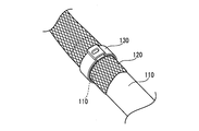
- the structure is such that three power cables (high voltage cables) 102U, 102V, and 102W connected to the inverter 100 mounted on the rear side are respectively passed through metal core shield pipes (protection pipes) 110 and forward on the lower side of the floor.
- metal core shield pipes protection pipes
- the three power cables 102U, 102V, and 102W are collectively passed through a flexible collective shield tube (protective tube) 120.
- the power cables 102U, 102V, and 102W are respectively passed through the rigid core shield pipes 110 in the wiring area below the floor, and are passed through the flexible collective shield tube 120 in the wiring area in the engine room.
- the power cables 102U, 102V, and 102W can be wired below the floor, and the space above the floor can be used effectively.
- the present invention has a small number of work man-hours and parts including a plurality of core shield pipes through which a plurality of electric wires are inserted for each electric wire, and one collective shield braided tube through which the wires drawn from the core shield pipes are focused and inserted.
- the problem is that it can be easily fixed and electrically connected by the number of points.
- the present invention is a wiring structure of a wire harness that is wired to a hybrid vehicle or an electric vehicle, A plurality of electric wires are passed through each core shield pipe made of a metal pipe for each electric wire, and each of the plurality of core shield pipes are in close proximity to each other in parallel, A plurality of electric wires drawn out from each of the core shield pipes, and a second region to be inserted into one collective shield braided tube formed by knitting metal wires in a mesh shape; and A plurality of core shield pipes in the first region and one collective shield braided tube in the second region are fixed and electrically connected using a metal bracket and a metal clamp,
- the metal bracket is formed from a pair of semicircular members obtained by dividing a circular disk sized to cover the collective shield braided tube, and each core shield pipe insertion groove formed of a semicircular recess is formed on the opposite side of the semicircular members.
- Each core shield pipe is brought into contact with each core shield pipe insertion groove and inserted, and the collective shield braided tube is covered on the outer periphery of the metal bracket made of the pair of semicircular members.
- a wiring harness wiring structure in which a metal clamp is externally fitted and fastened to the outer periphery of the wire harness, and the collective shield braided tube is fixed to each core shield pipe via the metal bracket with the metal clamp and electrically connected. ing.
- each core shield pipe insertion groove formed of a semicircular recess
- the metal bracket which consists of a pair of semicircle member which opposedly arranged at intervals is used. Therefore, each core shield pipe in the first region is inserted into the shield pipe insertion groove of the semicircular member, and the core shield pipes are inserted between the pair of semicircular members. Can be closely attached to the metal bracket without any gap. Further, the collective shield braided tube can be brought into close contact with the metal bracket only by covering the metal bracket with the second region collective shield braided tube and fitting the metal shield braided tube with a metal clamp.
- one collective shield braided tube can be easily fixed to each of the plurality of core shield pipes via the metal bracket, and the plurality of core shield pipes can be connected to the plurality of core shield pipes with a small number of work steps and parts.
- Two bulk shield braided tubes can be electrically connected.
- the metal clamp is ring-shaped, and consists of a caulking ring provided with a caulking projection on a part thereof.
- the metal bracket is clamped after the caulking ring is put on the outer periphery of the metal shield braided tube. It is preferably fixed.
- the metal clamp is composed of a pair of semi-annular members, bolt holes are provided on both sides of the semi-annular member, and the pair of the pair of semi-shielded braided tubes is sandwiched between the outer periphery of the metal bracket. After covering the semi-annular member, the bolt holes on both sides may be bolted and fixed with nuts.
- the pair of semicircular members of the metal bracket may be separated, but one end side may be connected to be freely opened and closed by a hinge. In this way, by connecting the pair of semicircular members with the hinges, the operation of sandwiching each core shield pipe between the pair of semicircular members is facilitated.
- the metal bracket is preferably formed of, for example, an aluminum-based or copper-based metal, and the metal clamp is preferably formed of an aluminum-based metal.
- the collective shield braided tube is preferably made of, for example, a copper-based metal wire, and each of the core shield pipes is preferably made of an aluminum-based metal.
- the first area is a wiring area below the vehicle floor
- the second area is a wiring area in the engine room.
- the lower part of the vehicle floor is an area that can be wired in a substantially straight line
- a plurality of electric wires connected to a rear-side device such as a battery are inserted into each core shield pipe for each electric wire as a first area for parallel piping.
- the vehicle space can be used effectively.
- the second plurality of wires drawn from the core shield pipes are converged and inserted into a flexible collectively shielded braided tube. A region is preferable.
- a plurality of electric wires inserted into the collective braided tube can be connected to a device such as an inverter in the engine room.
- each core shield pipe insertion groove formed of a semicircular recess
- the metal bracket which consists of a pair of semicircle member which opposedly arranged at intervals is used. Therefore, each core shield pipe inserted by simply inserting each core shield pipe in the first region into the shield pipe insertion groove provided in the semicircle member and sandwiching each core shield pipe between the pair of semicircle members. Can be closely attached to the metal bracket without any gap.
- the collective shield braided tube can be brought into close contact with the metal bracket only by covering the metal bracket with the collective shield braided tube in the second region and fitting and fastening the metal clamp to the collective shield braided tube.
- one collective shield braided tube can be easily fixed to each each core shield pipe via the said metal bracket, The said each core shield can be carried out with few work steps and parts count.
- the pipe and one collective shield braided tube can be electrically connected.
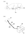
- the wiring structure of the wire harness in 1st Embodiment is shown, (A) is a schematic explanatory drawing of the state wired to the motor vehicle, (B) is a schematic plan view.
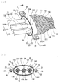
- the connection part of each core shield pipe and a collective shield braided tube is shown, (A) is a schematic perspective view, (B) is a sectional view along the line AA. It is a schematic exploded perspective view which shows a metal bracket.
- the connection part of each core shield pipe and a collective shield braided tube is shown in 2nd Embodiment, (A) is a schematic perspective view, (B) is a BB sectional drawing. It is a schematic perspective view which shows the metal bracket used in 2nd Embodiment (at the time of metal bracket open
- FIG. 1 show a first embodiment of the present invention.
- a wire harness is routed to connect the battery 1 mounted on the rear side and the inverter 4 mounted in the engine room 3.
- Three electric wires 10 (10A, 10B, 10C) constituting the wire harness are connected to the battery 1 on the rear side, wired below the floor 2, and connected to the inverter 4 in the engine room 3.
- the wiring area of the wire harness is wired from the rear side to the lower side of the floor 2 and drawn into the engine room 3 on the front side, and is wired in the engine room 3 continuously to the first area R1. It consists of 2nd area
- These core shield pipes 11 (11A, 11B, 11C) are arranged close to each other in parallel.
- the three electric wires 10 (10A, 10B, 10C) drawn from the three core shield pipes 11 (11A, 11B, 11C) are converged, and the copper-based metal wire is meshed. It is inserted through one collective shield braided tube 12 formed by knitting into a shape. In the second region R2, although not shown, a corrugated tube is sheathed on the collective shield braided tube 12.
- the distal end portion of one collective shield braided tube 12 is fixed to the distal end portion of each of the three core shield pipes 11 (11A, 11B, 11C).
- the metal bracket 13 and the metal clamp 16 made of an aluminum metal are used for fixing.
- the metal bracket 13 is composed of a pair of semicircular members 14 obtained by dividing a circular plate sized to cover the collective shield braided tube 12.
- the three core shield pipe insertion grooves 15 (15A, 15B, 15C) made of circular recesses are provided to face each other, and are arranged in parallel at intervals.
- the metal clamp 16 is a ring-shaped caulking ring as shown in FIG. 2, and a caulking protrusion 17 is provided on a part thereof.
- each core shield pipe 11 (11A, 11B, 11C).
- each core shield pipe insertion grooves 15 (15A, 15B, 15C) provided in the semicircular member 14 of the metal bracket 13 one by one, and the pair of semicircular members 14 of the metal bracket 13 are inserted.
- the metal bracket 13 composed of a pair of semicircular members 14 in which the core shield pipe insertion grooves 15 (15A, 15B, 15C) made of semicircular recesses are arranged to face each other with a space therebetween. Used. Therefore, the tip portions of the core shield pipes 11 (11A, 11B, 11C) in the first region R1 are inserted into the core shield pipe insertion grooves 15 (15A, 15B, 15C) of the semicircular member 14, and a pair of semicircles are inserted.
- each core shield pipe 11 11A, 11B, 11C
- the outer periphery of the tip portion of each core shield pipe 11 11A, 11B, 11C
- the metal bracket 13 covers the metal bracket 13 with the tip portion of the collective shield braided tube 12 in the second region R2, and by externally fitting and fastening the metal clamp 16 made of caulking on the outer periphery of the collective shield braided tube 12, the collective shield The distal end portion of the braided tube 12 can be brought into close contact with the metal bracket 13.
- the tip portion of one collective shield braided tube 12 can be easily fixed to the tip portions of the three core shield pipes 11 (11A, 11B, 11C) via the metal bracket 13.
- the three core shielded pipes 11 (11A, 11B, 11C) and one collective shield braided tube 12 can be electrically connected with a small number of work steps and parts.
- FIG. 4 and 5 show a second embodiment.
- a metal clamp 26 is formed from a pair of semi-annular members 27 provided with bolt holes 28 on both sides, and a bolt 29 is passed through the bolt hole 28 and fixed with a nut 30.
- the clamp 26 can be fastened.
- one end side of the pair of semicircular members 24 of the metal bracket 23 is connected by a hinge 31 so as to be freely opened and closed.
- Other points are the same as in the first embodiment.
- the tip portion of one collective shield braided tube 12 is connected to the tip portion of each of the three core shield pipes 11 (11A, 11B, 11C) via the metal bracket 23. Can be easily fixed and electrically connected.
Landscapes
- Engineering & Computer Science (AREA)
- Mechanical Engineering (AREA)
- Chemical & Material Sciences (AREA)
- Combustion & Propulsion (AREA)
- Transportation (AREA)
- Microelectronics & Electronic Packaging (AREA)
- Details Of Indoor Wiring (AREA)
- Installation Of Indoor Wiring (AREA)
- Shielding Devices Or Components To Electric Or Magnetic Fields (AREA)
- Arrangement Or Mounting Of Propulsion Units For Vehicles (AREA)
Abstract
Description
複数本の電線を電線毎に金属パイプからなる各芯シールドパイプに通し、これら複数本の各芯シールドパイプを近接して平行配管している第一領域と、
前記各芯シールドパイプから引き出された複数本の電線を、金属線をメッシュ状に編成して形成した1つの一括シールド編組チューブ内に挿通する第二領域とを設け、
前記第一領域の複数の各芯シールドパイプと第二領域の1つの一括シールド編組チューブとを金属ブラケットと金属クランプを用いて固定して電気接続しており、
前記金属ブラケットは、一括シールド編組チューブを被せる大きさとした円板を二分割した一対の半円部材から形成し、これら半円部材の対向辺に半円状凹部からなる各芯シールドパイプ挿通溝を対向して設けると共にそれぞれ間隔をあけて並設し、
前記各芯シールドパイプ挿通溝に前記各芯シールドパイプを1本ずつ接触させて挿通させ、該一対の半円部材からなる前記金属ブラケットの外周に前記一括シールド編組チューブを被せ、該一括シールド編組チューブの外周に金属クランプを外嵌して締結し、該金属クランプで前記一括シールド編組チューブを金属ブラケットを介して各芯シールドパイプに固定して電気接続しているワイヤハーネスの配索構造を提供している。
また、前記金属ブラケットに第二領域の一括シールド編組チューブを被せ該一括シールド編組チューブに金属クランプを外嵌して締結するだけで、前記一括シールド編組チューブを金属ブラケットに密着させることができる。
また、前記一括シールド編組チューブは例えば銅系金属線を編成したものが好ましく、前記各芯シールドパイプはアルミニウム系金属から形成していることが好ましい。
このように前記構成によれば、前記金属ブラケットを介して1つの一括シールド編組チューブを複数の各芯シールドパイプに容易に固定することができ、少ない作業工数、部品点数で前記複数の各芯シールドパイプと1つの一括シールド編組チューブとを電気接続することができる。
図1乃至図3は本発明の第1実施形態を示している。本実施形態ではハイブリッド自動車において、図1に示すように、リア側に搭載したバッテリ1とエンジンルーム3内に搭載したインバータ4とを接続するためにワイヤハーネスを配索している。ワイヤハーネスを構成する3本の電線10(10A、10B、10C)をリア側のバッテリ1に接続してフロア2の下方を配線し、エンジンルーム3内のインバータ4に接続している。
また、金属クランプ16は図2に示すような環形状のカシメリングであり、その一部にカシメ突起部17を設けている。
最後に、カシメリングからなる金属クランプ16を金属ブラケット13の外周に前記一括シールド編組チューブ12の先端部分を挟んで被せた後、該金属クランプ16のカシメ突起部17を加締めて固定する。これにより、3本の各芯シールドパイプ11(11A、11B、11C)と1つの一括シールド編組チューブ12との固定が完了する。
また、金属ブラケット13に第二領域R2の一括シールド編組チューブ12の先端部分を被せ、該一括シールド編組チューブ12の外周にカシメリングからなる金属クランプ16を外嵌して締結するだけで、一括シールド編組チューブ12の先端部分を金属ブラケット13に密着させることができる。
第2実施形態では、図4のように、両側にボルト穴28を設けた一対の半円環部材27から金属クランプ26を形成し、ボルト穴28にボルト29を通してナット30で固定することにより金属クランプ26を締結できるようにしている。また、図5のように、金属ブラケット23の一対の半円部材24の一端側をヒンジ31で連結し、開閉自在としている。その他の点は第1実施形態と同様としている。
11 各芯シールドパイプ
12 一括シールド編組チューブ
13、23 金属ブラケット
14、24 半円部材
15、25 各芯シールドパイプ挿通溝
31 ヒンジ
16、26 金属クランプ
17 カシメ突起部
27 半円環部材
28 ボルト穴
29 ボルト
30 ナット
Claims (5)
- ハイブリッド自動車または電気自動車に配索するワイヤハーネスの配索構造であって、
複数本の電線を電線毎に金属パイプからなる各芯シールドパイプに通し、これら複数本の各芯シールドパイプを近接して平行配管している第一領域と、
前記各芯シールドパイプから引き出された複数本の電線を、金属線をメッシュ状に編成して形成した1つの一括シールド編組チューブ内に挿通する第二領域とを設け、
前記第一領域の複数の各芯シールドパイプと第二領域の1つの一括シールド編組チューブとを金属ブラケットと金属クランプを用いて固定して電気接続しており、
前記金属ブラケットは、一括シールド編組チューブを被せる大きさとした円板を二分割した一対の半円部材から形成し、これら半円部材の対向辺に半円状凹部からなる各芯シールドパイプ挿通溝を対向して設けると共にそれぞれ間隔をあけて並設し、
前記各芯シールドパイプ挿通溝に前記各芯シールドパイプを1本ずつ接触させて挿通させ、該一対の半円部材からなる前記金属ブラケットの外周に前記一括シールド編組チューブを被せ、該一括シールド編組チューブの外周に金属クランプを外嵌して締結し、該金属クランプで前記一括シールド編組チューブを金属ブラケットを介して各芯シールドパイプに固定して電気接続しているワイヤハーネスの配索構造。 - 前記金属クランプは環形状で、その一部にカシメ突起部を設けたカシメリングからなり、前記金属ブラケットの外周に前記一括シールド編組チューブの先端部分を挟んで前記カシメリングを被せた後に加締めて固定している請求項1に記載のワイヤハーネスの配索構造。
- 前記金属クランプは一対の半円環部材からなり、該半円環部材の両側にボルト穴を設けており、前記金属ブラケットの外周に前記一括シールド編組チューブの先端部分を挟んで前記一対の半円環部材を被せた後に前記両側のボルト穴にボルトを通してナットで固定している請求項1に記載のワイヤハーネスの配索構造。
- 前記金属ブラケットの一対の半円部材は一端側をヒンジで開閉自在に連結している請求項1乃至請求項3のいずれか1項に記載のワイヤハーネスの配索構造。
- 前記第一領域は車両フロア下方の配線領域であり、前記第二領域はエンジンルーム内の配線領域である請求項1乃至請求項4のいずれか1項に記載のワイヤハーネスの配索構造。
Priority Applications (4)
| Application Number | Priority Date | Filing Date | Title |
|---|---|---|---|
| DE112010005333T DE112010005333T5 (de) | 2010-03-02 | 2010-10-28 | Kabelbaumanordnungsstruktur |
| US13/574,891 US8981221B2 (en) | 2010-03-02 | 2010-10-28 | Wiring harness arrangement structure |
| KR1020127022578A KR101325428B1 (ko) | 2010-03-02 | 2010-10-28 | 와이어 하네스 배치 구조 |
| CN201080065074.3A CN102781729B (zh) | 2010-03-02 | 2010-10-28 | 线束的布置结构 |
Applications Claiming Priority (2)
| Application Number | Priority Date | Filing Date | Title |
|---|---|---|---|
| JP2010045934A JP5293644B2 (ja) | 2010-03-02 | 2010-03-02 | ワイヤハーネスの配索構造 |
| JP2010-045934 | 2010-03-02 |
Publications (1)
| Publication Number | Publication Date |
|---|---|
| WO2011108141A1 true WO2011108141A1 (ja) | 2011-09-09 |
Family
ID=44541817
Family Applications (1)
| Application Number | Title | Priority Date | Filing Date |
|---|---|---|---|
| PCT/JP2010/069138 Ceased WO2011108141A1 (ja) | 2010-03-02 | 2010-10-28 | ワイヤハーネスの配索構造 |
Country Status (6)
| Country | Link |
|---|---|
| US (1) | US8981221B2 (ja) |
| JP (1) | JP5293644B2 (ja) |
| KR (1) | KR101325428B1 (ja) |
| CN (1) | CN102781729B (ja) |
| DE (1) | DE112010005333T5 (ja) |
| WO (1) | WO2011108141A1 (ja) |
Cited By (3)
| Publication number | Priority date | Publication date | Assignee | Title |
|---|---|---|---|---|
| JP2013176279A (ja) * | 2012-01-23 | 2013-09-05 | Auto Network Gijutsu Kenkyusho:Kk | 電磁シールド具及びワイヤハーネス |
| EP2915171A4 (en) * | 2012-10-31 | 2016-07-13 | Delphi Tech Inc | DEVICE AND METHOD FOR SPLITTING SHIELDED WIRED CABLE |
| US20220161743A1 (en) * | 2019-03-27 | 2022-05-26 | Sumitomo Wiring Systems, Limited | Wire harness |
Families Citing this family (30)
| Publication number | Priority date | Publication date | Assignee | Title |
|---|---|---|---|---|
| JP5830339B2 (ja) * | 2011-10-11 | 2015-12-09 | 矢崎総業株式会社 | 編組及びワイヤハーネス |
| JP2013235749A (ja) * | 2012-05-10 | 2013-11-21 | Auto Network Gijutsu Kenkyusho:Kk | ワイヤハーネス |
| JP5846041B2 (ja) * | 2012-05-15 | 2016-01-20 | 株式会社オートネットワーク技術研究所 | ワイヤハーネス |
| JP5874549B2 (ja) * | 2012-06-29 | 2016-03-02 | 三菱自動車工業株式会社 | 電動車両 |
| JP6094852B2 (ja) * | 2012-09-15 | 2017-03-15 | スズキ株式会社 | 車両の高電圧ケーブル配索構造 |
| DE112013004880T5 (de) * | 2012-10-05 | 2015-06-18 | Sumitomo Wiring Systems, Ltd. | Kabelstrang |
| JP6169371B2 (ja) * | 2013-02-28 | 2017-07-26 | 矢崎総業株式会社 | シールド部材及びこの製造方法 |
| US9444187B2 (en) * | 2013-04-15 | 2016-09-13 | Toyota Jidosha Kabushiki Kaisha | Vehicle |
| DE102013211879A1 (de) * | 2013-06-24 | 2014-12-24 | Bayerische Motoren Werke Aktiengesellschaft | Fixieranordnung für ein Fahrzeug |
| JP6008251B2 (ja) * | 2013-08-23 | 2016-10-19 | 住友電装株式会社 | 導電路及び導電路用スペーサ |
| JP5971563B2 (ja) * | 2013-11-29 | 2016-08-17 | 住友電装株式会社 | 電線のシールド構造 |
| JP6149800B2 (ja) * | 2014-05-15 | 2017-06-21 | 住友電装株式会社 | シールド導電路 |
| JP6281448B2 (ja) * | 2014-09-03 | 2018-02-21 | 住友電装株式会社 | 導電路 |
| JP6256308B2 (ja) * | 2014-11-06 | 2018-01-10 | 住友電装株式会社 | ワイヤハーネスのシールド構造 |
| JP6361544B2 (ja) * | 2015-03-24 | 2018-07-25 | 株式会社オートネットワーク技術研究所 | 電磁シールド部材 |
| JP6252538B2 (ja) * | 2015-04-06 | 2017-12-27 | 株式会社オートネットワーク技術研究所 | 外装部材付配線モジュール |
| JP6519797B2 (ja) * | 2015-11-10 | 2019-05-29 | 住友電装株式会社 | シールド導電路 |
| JP6614017B2 (ja) * | 2016-04-28 | 2019-12-04 | 株式会社オートネットワーク技術研究所 | 電磁シールド具及びワイヤーハーネス |
| JP6419123B2 (ja) * | 2016-09-13 | 2018-11-07 | 本田技研工業株式会社 | 電力機器ユニット及び車両 |
| JP6686864B2 (ja) * | 2016-12-19 | 2020-04-22 | 住友電装株式会社 | ワイヤハーネス |
| JP6763346B2 (ja) * | 2017-01-23 | 2020-09-30 | 株式会社オートネットワーク技術研究所 | 電磁シールド部品及びワイヤハーネス |
| JP6794883B2 (ja) * | 2017-03-15 | 2020-12-02 | 株式会社オートネットワーク技術研究所 | 電磁シールド部品及びワイヤハーネス |
| CN110447152A (zh) * | 2017-03-16 | 2019-11-12 | 住友电装株式会社 | 电线布线构件及电线布线结构 |
| JP6700613B2 (ja) * | 2017-03-22 | 2020-05-27 | 株式会社オートネットワーク技術研究所 | 導電線 |
| JP7000075B2 (ja) * | 2017-08-29 | 2022-02-10 | 矢崎総業株式会社 | 車両用回路体 |
| CN107492406A (zh) * | 2017-09-22 | 2017-12-19 | 贵州固达电缆有限公司 | 一种用于汽车内的特殊电缆 |
| JP7440899B2 (ja) * | 2020-03-31 | 2024-02-29 | 北川工業株式会社 | 電磁ノイズ対策部材 |
| KR102347766B1 (ko) * | 2020-09-14 | 2022-01-05 | 현대자동차주식회사 | 차량용 구동모터 모듈 |
| JP7261215B6 (ja) * | 2020-12-18 | 2023-05-10 | 矢崎総業株式会社 | 編組接続構造 |
| JP2024113898A (ja) * | 2023-02-10 | 2024-08-23 | 株式会社オートネットワーク技術研究所 | 長尺物支持構造体及び長尺物支持具 |
Citations (4)
| Publication number | Priority date | Publication date | Assignee | Title |
|---|---|---|---|---|
| JP2008204805A (ja) * | 2007-02-20 | 2008-09-04 | Auto Network Gijutsu Kenkyusho:Kk | シールド導電体及びその製造方法 |
| JP2009021254A (ja) * | 2008-08-01 | 2009-01-29 | Hitachi Cable Ltd | シールド電線 |
| JP2009135240A (ja) * | 2007-11-29 | 2009-06-18 | Furukawa Electric Co Ltd:The | 電線のシールド構造 |
| JP2010040396A (ja) * | 2008-08-06 | 2010-02-18 | Hitachi Cable Ltd | シールドワイヤーハーネスとその製造方法 |
Family Cites Families (22)
| Publication number | Priority date | Publication date | Assignee | Title |
|---|---|---|---|---|
| US3867565A (en) * | 1973-08-31 | 1975-02-18 | Us Navy | Electrical conductive coated cable |
| DE4039822C1 (ja) * | 1990-12-13 | 1992-07-23 | A. Raymond Kg, 7850 Loerrach, De | |
| US5669590A (en) * | 1995-12-04 | 1997-09-23 | Yazaki Corporation | Retaining clip with multiple clamps |
| USD390447S (en) * | 1996-10-25 | 1998-02-10 | Colen Jr Eddie D | Electrical wire separator |
| US6203376B1 (en) * | 1999-12-15 | 2001-03-20 | Molex Incorporated | Cable wafer connector with integrated strain relief |
| JP4092086B2 (ja) * | 2000-06-30 | 2008-05-28 | 矢崎総業株式会社 | コルゲートチューブ固定具 |
| CN2441005Y (zh) * | 2000-08-28 | 2001-08-01 | 上海满水化学品有限公司 | 转载型节能支吊架 |
| JP2003264040A (ja) * | 2002-03-08 | 2003-09-19 | Auto Network Gijutsu Kenkyusho:Kk | シールド電線 |
| JP2004009996A (ja) * | 2002-06-11 | 2004-01-15 | Sumitomo Electric Ind Ltd | 車体内の電線固定構造 |
| JP3966407B2 (ja) * | 2002-09-24 | 2007-08-29 | 矢崎総業株式会社 | 防油水性を備えた電磁波シールド構造 |
| JP3909763B2 (ja) * | 2002-11-20 | 2007-04-25 | 株式会社オートネットワーク技術研究所 | シールド機能を備えた車両用導電路 |
| JP2004224156A (ja) | 2003-01-22 | 2004-08-12 | Honda Motor Co Ltd | 車両用電力ケーブル保持構造 |
| US20080264102A1 (en) * | 2004-02-23 | 2008-10-30 | Bolton Medical, Inc. | Sheath Capture Device for Stent Graft Delivery System and Method for Operating Same |
| JP4649213B2 (ja) * | 2004-03-08 | 2011-03-09 | 株式会社オートネットワーク技術研究所 | シールドワイヤーハーネスの製造方法及びシールドケーブルの端末構造 |
| US7247795B2 (en) * | 2004-12-06 | 2007-07-24 | Hitachi Cable. Ltd. | Shield wire, housing connected with same, connecting method thereof and shield wire unit |
| WO2007029801A1 (ja) * | 2005-09-08 | 2007-03-15 | Autonetworks Technologies, Ltd. | 車両用シールド導電体 |
| JP4674175B2 (ja) * | 2005-10-24 | 2011-04-20 | 矢崎総業株式会社 | スライド構造体用の給電装置 |
| US7561445B2 (en) * | 2005-11-10 | 2009-07-14 | Nissan Motor Co., Ltd. | Harness routing structure for vehicle |
| JP4767760B2 (ja) * | 2006-06-02 | 2011-09-07 | 住友電装株式会社 | シールド電線用アース端子 |
| US8013249B2 (en) * | 2006-11-24 | 2011-09-06 | Autonetworks Technologies, Ltd. | Shield conductor and shield conductor manufacturing method |
| CN201191734Y (zh) * | 2008-04-29 | 2009-02-04 | 重庆长安汽车股份有限公司 | 一种混合动力汽车用动力线束护线盒 |
| JP2010040936A (ja) * | 2008-08-07 | 2010-02-18 | Kyocer Slc Technologies Corp | 配線基板およびその製造方法 |
-
2010
- 2010-03-02 JP JP2010045934A patent/JP5293644B2/ja not_active Expired - Fee Related
- 2010-10-28 WO PCT/JP2010/069138 patent/WO2011108141A1/ja not_active Ceased
- 2010-10-28 KR KR1020127022578A patent/KR101325428B1/ko not_active Expired - Fee Related
- 2010-10-28 DE DE112010005333T patent/DE112010005333T5/de not_active Ceased
- 2010-10-28 US US13/574,891 patent/US8981221B2/en not_active Expired - Fee Related
- 2010-10-28 CN CN201080065074.3A patent/CN102781729B/zh not_active Expired - Fee Related
Patent Citations (4)
| Publication number | Priority date | Publication date | Assignee | Title |
|---|---|---|---|---|
| JP2008204805A (ja) * | 2007-02-20 | 2008-09-04 | Auto Network Gijutsu Kenkyusho:Kk | シールド導電体及びその製造方法 |
| JP2009135240A (ja) * | 2007-11-29 | 2009-06-18 | Furukawa Electric Co Ltd:The | 電線のシールド構造 |
| JP2009021254A (ja) * | 2008-08-01 | 2009-01-29 | Hitachi Cable Ltd | シールド電線 |
| JP2010040396A (ja) * | 2008-08-06 | 2010-02-18 | Hitachi Cable Ltd | シールドワイヤーハーネスとその製造方法 |
Cited By (5)
| Publication number | Priority date | Publication date | Assignee | Title |
|---|---|---|---|---|
| JP2013176279A (ja) * | 2012-01-23 | 2013-09-05 | Auto Network Gijutsu Kenkyusho:Kk | 電磁シールド具及びワイヤハーネス |
| EP2915171A4 (en) * | 2012-10-31 | 2016-07-13 | Delphi Tech Inc | DEVICE AND METHOD FOR SPLITTING SHIELDED WIRED CABLE |
| US9917434B2 (en) | 2012-10-31 | 2018-03-13 | Delphi Technologies, Inc. | Device and method for splicing shielded wire cables |
| US20220161743A1 (en) * | 2019-03-27 | 2022-05-26 | Sumitomo Wiring Systems, Limited | Wire harness |
| US11904781B2 (en) * | 2019-03-27 | 2024-02-20 | Sumitomo Wiring Systems, Limited | Wire harness with body protrusion |
Also Published As
| Publication number | Publication date |
|---|---|
| KR20120128134A (ko) | 2012-11-26 |
| JP5293644B2 (ja) | 2013-09-18 |
| JP2011178324A (ja) | 2011-09-15 |
| CN102781729B (zh) | 2015-04-01 |
| US20120312595A1 (en) | 2012-12-13 |
| US8981221B2 (en) | 2015-03-17 |
| KR101325428B1 (ko) | 2013-11-04 |
| DE112010005333T5 (de) | 2012-12-13 |
| CN102781729A (zh) | 2012-11-14 |
Similar Documents
| Publication | Publication Date | Title |
|---|---|---|
| JP5293644B2 (ja) | ワイヤハーネスの配索構造 | |
| JP3947096B2 (ja) | シールド機能を備えた導電路及びシールド部材 | |
| JP5986812B2 (ja) | ワイヤハーネス | |
| CN107548532B (zh) | 屏蔽线束、屏蔽部件和屏蔽线束的制造方法 | |
| CN103415968B (zh) | 屏蔽导体 | |
| US10236634B2 (en) | Electromagnetic shield member and electromagnetic shield member-equipped wiring device | |
| JP5478169B2 (ja) | ワイヤハーネスの配索方法 | |
| JP2011173456A (ja) | ワイヤハーネスの配索構造 | |
| JP5692003B2 (ja) | インバータとモータ内蔵ドライブトレインとの電気的接続構造 | |
| WO2012032796A1 (ja) | 自動車の配線構造 | |
| JP2019032974A (ja) | ワイヤハーネス | |
| WO2019142871A1 (ja) | 導電路及びワイヤハーネス | |
| CN104334413A (zh) | 带有固定部件的线束 | |
| CN105993051A (zh) | 电线的屏蔽结构 | |
| JP2015201284A (ja) | ワイヤハーネス | |
| JP2014086152A (ja) | シールドコネクタ | |
| JP6644573B2 (ja) | シールドパイプ、及び、シールドパイプ付き電線 | |
| JP4787535B2 (ja) | シールド導電体の取付け構造 | |
| JP6409672B2 (ja) | 電線モジュール | |
| JP2011205843A (ja) | フラット電線用クランプ | |
| JP4820573B2 (ja) | シールド導電路 | |
| JP2012064331A (ja) | ワイヤーハーネス | |
| JP2015012778A (ja) | フレキシブルパイプ | |
| JP5097388B2 (ja) | シールド導電体及びシールド導電体の接続部材 | |
| JP2018129971A (ja) | ワイヤハーネスの配索構造 |
Legal Events
| Date | Code | Title | Description |
|---|---|---|---|
| WWE | Wipo information: entry into national phase |
Ref document number: 201080065074.3 Country of ref document: CN |
|
| 121 | Ep: the epo has been informed by wipo that ep was designated in this application |
Ref document number: 10847038 Country of ref document: EP Kind code of ref document: A1 |
|
| WWE | Wipo information: entry into national phase |
Ref document number: 13574891 Country of ref document: US |
|
| ENP | Entry into the national phase |
Ref document number: 20127022578 Country of ref document: KR Kind code of ref document: A |
|
| WWE | Wipo information: entry into national phase |
Ref document number: 1120100053332 Country of ref document: DE Ref document number: 112010005333 Country of ref document: DE |
|
| 122 | Ep: pct application non-entry in european phase |
Ref document number: 10847038 Country of ref document: EP Kind code of ref document: A1 |