WO2011105301A1 - 負極及びアルミニウム空気電池 - Google Patents
負極及びアルミニウム空気電池 Download PDFInfo
- Publication number
- WO2011105301A1 WO2011105301A1 PCT/JP2011/053556 JP2011053556W WO2011105301A1 WO 2011105301 A1 WO2011105301 A1 WO 2011105301A1 JP 2011053556 W JP2011053556 W JP 2011053556W WO 2011105301 A1 WO2011105301 A1 WO 2011105301A1
- Authority
- WO
- WIPO (PCT)
- Prior art keywords
- aluminum
- negative electrode
- alloy
- air battery
- less
- Prior art date
Links
- 229910052782 aluminium Inorganic materials 0.000 title claims abstract description 130
- XAGFODPZIPBFFR-UHFFFAOYSA-N aluminium Chemical compound [Al] XAGFODPZIPBFFR-UHFFFAOYSA-N 0.000 title claims abstract description 127
- 229910000838 Al alloy Inorganic materials 0.000 claims abstract description 75
- 229910045601 alloy Inorganic materials 0.000 claims abstract description 57
- 239000000956 alloy Substances 0.000 claims abstract description 57
- 239000011777 magnesium Substances 0.000 claims abstract description 41
- XEEYBQQBJWHFJM-UHFFFAOYSA-N Iron Chemical compound [Fe] XEEYBQQBJWHFJM-UHFFFAOYSA-N 0.000 claims abstract description 31
- 229910052749 magnesium Inorganic materials 0.000 claims abstract description 23
- FYYHWMGAXLPEAU-UHFFFAOYSA-N Magnesium Chemical compound [Mg] FYYHWMGAXLPEAU-UHFFFAOYSA-N 0.000 claims abstract description 18
- 229910052742 iron Inorganic materials 0.000 claims abstract description 18
- 229910052710 silicon Inorganic materials 0.000 claims abstract description 11
- XUIMIQQOPSSXEZ-UHFFFAOYSA-N Silicon Chemical compound [Si] XUIMIQQOPSSXEZ-UHFFFAOYSA-N 0.000 claims abstract description 9
- 239000010703 silicon Substances 0.000 claims abstract description 9
- 239000002245 particle Substances 0.000 claims description 46
- QVGXLLKOCUKJST-UHFFFAOYSA-N atomic oxygen Chemical compound [O] QVGXLLKOCUKJST-UHFFFAOYSA-N 0.000 claims description 33
- 239000001301 oxygen Substances 0.000 claims description 33
- 229910052760 oxygen Inorganic materials 0.000 claims description 33
- 239000003054 catalyst Substances 0.000 claims description 26
- WABPQHHGFIMREM-UHFFFAOYSA-N lead(0) Chemical compound [Pb] WABPQHHGFIMREM-UHFFFAOYSA-N 0.000 claims description 26
- 239000003792 electrolyte Substances 0.000 claims description 21
- 239000000463 material Substances 0.000 claims description 17
- 229910000765 intermetallic Inorganic materials 0.000 claims description 16
- BASFCYQUMIYNBI-UHFFFAOYSA-N platinum Chemical compound [Pt] BASFCYQUMIYNBI-UHFFFAOYSA-N 0.000 claims description 10
- 239000011572 manganese Substances 0.000 claims description 8
- NUJOXMJBOLGQSY-UHFFFAOYSA-N manganese dioxide Chemical compound O=[Mn]=O NUJOXMJBOLGQSY-UHFFFAOYSA-N 0.000 claims description 8
- 229910052804 chromium Inorganic materials 0.000 claims description 6
- 239000002131 composite material Substances 0.000 claims description 5
- 229910052748 manganese Inorganic materials 0.000 claims description 5
- 229910052697 platinum Inorganic materials 0.000 claims description 5
- 239000011159 matrix material Substances 0.000 claims description 4
- 229910052746 lanthanum Inorganic materials 0.000 claims description 3
- 238000004519 manufacturing process Methods 0.000 description 72
- 238000005259 measurement Methods 0.000 description 25
- 230000000052 comparative effect Effects 0.000 description 21
- 238000012360 testing method Methods 0.000 description 19
- HEMHJVSKTPXQMS-UHFFFAOYSA-M Sodium hydroxide Chemical compound [OH-].[Na+] HEMHJVSKTPXQMS-UHFFFAOYSA-M 0.000 description 18
- 238000009792 diffusion process Methods 0.000 description 17
- 239000008151 electrolyte solution Substances 0.000 description 17
- PXHVJJICTQNCMI-UHFFFAOYSA-N Nickel Chemical compound [Ni] PXHVJJICTQNCMI-UHFFFAOYSA-N 0.000 description 16
- KWYUFKZDYYNOTN-UHFFFAOYSA-M Potassium hydroxide Chemical compound [OH-].[K+] KWYUFKZDYYNOTN-UHFFFAOYSA-M 0.000 description 15
- 238000005260 corrosion Methods 0.000 description 15
- 230000007797 corrosion Effects 0.000 description 14
- -1 polyethylene Polymers 0.000 description 14
- 239000000243 solution Substances 0.000 description 10
- 229920001343 polytetrafluoroethylene Polymers 0.000 description 9
- 239000004810 polytetrafluoroethylene Substances 0.000 description 9
- 238000012545 processing Methods 0.000 description 9
- 239000010949 copper Substances 0.000 description 8
- 229910052751 metal Inorganic materials 0.000 description 8
- 239000002184 metal Substances 0.000 description 8
- 229910052759 nickel Inorganic materials 0.000 description 8
- 229920005989 resin Polymers 0.000 description 8
- 239000011347 resin Substances 0.000 description 8
- 239000007864 aqueous solution Substances 0.000 description 7
- 238000005097 cold rolling Methods 0.000 description 7
- 238000000034 method Methods 0.000 description 7
- 239000010936 titanium Substances 0.000 description 7
- OKTJSMMVPCPJKN-UHFFFAOYSA-N Carbon Chemical compound [C] OKTJSMMVPCPJKN-UHFFFAOYSA-N 0.000 description 6
- 229910052719 titanium Inorganic materials 0.000 description 6
- RTAQQCXQSZGOHL-UHFFFAOYSA-N Titanium Chemical compound [Ti] RTAQQCXQSZGOHL-UHFFFAOYSA-N 0.000 description 5
- 239000011651 chromium Substances 0.000 description 5
- 229910052802 copper Inorganic materials 0.000 description 5
- 238000005098 hot rolling Methods 0.000 description 5
- 150000003949 imides Chemical class 0.000 description 5
- 238000000879 optical micrograph Methods 0.000 description 5
- 238000009489 vacuum treatment Methods 0.000 description 5
- RYGMFSIKBFXOCR-UHFFFAOYSA-N Copper Chemical compound [Cu] RYGMFSIKBFXOCR-UHFFFAOYSA-N 0.000 description 4
- 239000002033 PVDF binder Substances 0.000 description 4
- 239000004698 Polyethylene Substances 0.000 description 4
- 239000004743 Polypropylene Substances 0.000 description 4
- 239000012528 membrane Substances 0.000 description 4
- 150000002739 metals Chemical class 0.000 description 4
- 229920000573 polyethylene Polymers 0.000 description 4
- 229920001155 polypropylene Polymers 0.000 description 4
- 229920002981 polyvinylidene fluoride Polymers 0.000 description 4
- VYZAMTAEIAYCRO-UHFFFAOYSA-N Chromium Chemical compound [Cr] VYZAMTAEIAYCRO-UHFFFAOYSA-N 0.000 description 3
- PWHULOQIROXLJO-UHFFFAOYSA-N Manganese Chemical compound [Mn] PWHULOQIROXLJO-UHFFFAOYSA-N 0.000 description 3
- 239000006230 acetylene black Substances 0.000 description 3
- 239000003125 aqueous solvent Substances 0.000 description 3
- 239000011230 binding agent Substances 0.000 description 3
- 239000006258 conductive agent Substances 0.000 description 3
- 239000004020 conductor Substances 0.000 description 3
- 238000005530 etching Methods 0.000 description 3
- 238000002360 preparation method Methods 0.000 description 3
- 238000005096 rolling process Methods 0.000 description 3
- 229910001220 stainless steel Inorganic materials 0.000 description 3
- 239000010935 stainless steel Substances 0.000 description 3
- BFKJFAAPBSQJPD-UHFFFAOYSA-N tetrafluoroethene Chemical group FC(F)=C(F)F BFKJFAAPBSQJPD-UHFFFAOYSA-N 0.000 description 3
- XLYOFNOQVPJJNP-UHFFFAOYSA-N water Substances O XLYOFNOQVPJJNP-UHFFFAOYSA-N 0.000 description 3
- 229910001018 Cast iron Inorganic materials 0.000 description 2
- QAOWNCQODCNURD-UHFFFAOYSA-N Sulfuric acid Chemical compound OS(O)(=O)=O QAOWNCQODCNURD-UHFFFAOYSA-N 0.000 description 2
- YJZATOSJMRIRIW-UHFFFAOYSA-N [Ir]=O Chemical class [Ir]=O YJZATOSJMRIRIW-UHFFFAOYSA-N 0.000 description 2
- 239000000853 adhesive Substances 0.000 description 2
- 230000001070 adhesive effect Effects 0.000 description 2
- IZJSTXINDUKPRP-UHFFFAOYSA-N aluminum lead Chemical compound [Al].[Pb] IZJSTXINDUKPRP-UHFFFAOYSA-N 0.000 description 2
- 238000000137 annealing Methods 0.000 description 2
- 239000003575 carbonaceous material Substances 0.000 description 2
- 239000000460 chlorine Substances 0.000 description 2
- 150000001875 compounds Chemical class 0.000 description 2
- 229920001577 copolymer Polymers 0.000 description 2
- 229920001038 ethylene copolymer Polymers 0.000 description 2
- 229910052733 gallium Inorganic materials 0.000 description 2
- 238000005470 impregnation Methods 0.000 description 2
- 238000002354 inductively-coupled plasma atomic emission spectroscopy Methods 0.000 description 2
- 229910000457 iridium oxide Inorganic materials 0.000 description 2
- 238000010030 laminating Methods 0.000 description 2
- 238000002156 mixing Methods 0.000 description 2
- 239000004745 nonwoven fabric Substances 0.000 description 2
- 229920000098 polyolefin Polymers 0.000 description 2
- 229910018084 Al-Fe Inorganic materials 0.000 description 1
- 229910018134 Al-Mg Inorganic materials 0.000 description 1
- 229910018192 Al—Fe Inorganic materials 0.000 description 1
- 229910018467 Al—Mg Inorganic materials 0.000 description 1
- KZBUYRJDOAKODT-UHFFFAOYSA-N Chlorine Chemical compound ClCl KZBUYRJDOAKODT-UHFFFAOYSA-N 0.000 description 1
- YCKRFDGAMUMZLT-UHFFFAOYSA-N Fluorine atom Chemical compound [F] YCKRFDGAMUMZLT-UHFFFAOYSA-N 0.000 description 1
- GYHNNYVSQQEPJS-UHFFFAOYSA-N Gallium Chemical compound [Ga] GYHNNYVSQQEPJS-UHFFFAOYSA-N 0.000 description 1
- UFHFLCQGNIYNRP-UHFFFAOYSA-N Hydrogen Chemical compound [H][H] UFHFLCQGNIYNRP-UHFFFAOYSA-N 0.000 description 1
- 229910019018 Mg 2 Si Inorganic materials 0.000 description 1
- 239000004793 Polystyrene Substances 0.000 description 1
- ATJFFYVFTNAWJD-UHFFFAOYSA-N Tin Chemical compound [Sn] ATJFFYVFTNAWJD-UHFFFAOYSA-N 0.000 description 1
- QCWXUUIWCKQGHC-UHFFFAOYSA-N Zirconium Chemical compound [Zr] QCWXUUIWCKQGHC-UHFFFAOYSA-N 0.000 description 1
- 239000002253 acid Substances 0.000 description 1
- 229920000122 acrylonitrile butadiene styrene Polymers 0.000 description 1
- 239000004676 acrylonitrile butadiene styrene Substances 0.000 description 1
- 239000011149 active material Substances 0.000 description 1
- 239000003513 alkali Substances 0.000 description 1
- 238000004458 analytical method Methods 0.000 description 1
- 238000007664 blowing Methods 0.000 description 1
- 230000003197 catalytic effect Effects 0.000 description 1
- UUAGAQFQZIEFAH-UHFFFAOYSA-N chlorotrifluoroethylene Chemical group FC(F)=C(F)Cl UUAGAQFQZIEFAH-UHFFFAOYSA-N 0.000 description 1
- BIJOYKCOMBZXAE-UHFFFAOYSA-N chromium iron nickel Chemical compound [Cr].[Fe].[Ni] BIJOYKCOMBZXAE-UHFFFAOYSA-N 0.000 description 1
- 238000001816 cooling Methods 0.000 description 1
- ZOMNIUBKTOKEHS-UHFFFAOYSA-L dimercury dichloride Chemical class Cl[Hg][Hg]Cl ZOMNIUBKTOKEHS-UHFFFAOYSA-L 0.000 description 1
- 229920006332 epoxy adhesive Polymers 0.000 description 1
- 239000003822 epoxy resin Substances 0.000 description 1
- 238000011156 evaluation Methods 0.000 description 1
- 230000002349 favourable effect Effects 0.000 description 1
- 229910052731 fluorine Inorganic materials 0.000 description 1
- 239000011737 fluorine Substances 0.000 description 1
- 230000004907 flux Effects 0.000 description 1
- 238000005242 forging Methods 0.000 description 1
- 229910002804 graphite Inorganic materials 0.000 description 1
- 239000010439 graphite Substances 0.000 description 1
- 238000007654 immersion Methods 0.000 description 1
- 239000011261 inert gas Substances 0.000 description 1
- 239000011810 insulating material Substances 0.000 description 1
- 150000002500 ions Chemical class 0.000 description 1
- 229910052741 iridium Inorganic materials 0.000 description 1
- GKOZUEZYRPOHIO-UHFFFAOYSA-N iridium atom Chemical compound [Ir] GKOZUEZYRPOHIO-UHFFFAOYSA-N 0.000 description 1
- 239000003273 ketjen black Substances 0.000 description 1
- AMWRITDGCCNYAT-UHFFFAOYSA-L manganese oxide Inorganic materials [Mn].O[Mn]=O.O[Mn]=O AMWRITDGCCNYAT-UHFFFAOYSA-L 0.000 description 1
- PPNAOCWZXJOHFK-UHFFFAOYSA-N manganese(2+);oxygen(2-) Chemical class [O-2].[Mn+2] PPNAOCWZXJOHFK-UHFFFAOYSA-N 0.000 description 1
- 239000000155 melt Substances 0.000 description 1
- 229910000623 nickel–chromium alloy Inorganic materials 0.000 description 1
- 229910052758 niobium Inorganic materials 0.000 description 1
- 239000010955 niobium Substances 0.000 description 1
- GUCVJGMIXFAOAE-UHFFFAOYSA-N niobium atom Chemical compound [Nb] GUCVJGMIXFAOAE-UHFFFAOYSA-N 0.000 description 1
- 230000003287 optical effect Effects 0.000 description 1
- 230000000704 physical effect Effects 0.000 description 1
- 238000005498 polishing Methods 0.000 description 1
- 229920002493 poly(chlorotrifluoroethylene) Polymers 0.000 description 1
- 239000005023 polychlorotrifluoroethylene (PCTFE) polymer Substances 0.000 description 1
- 229920000647 polyepoxide Polymers 0.000 description 1
- 229920000642 polymer Polymers 0.000 description 1
- 229920002223 polystyrene Polymers 0.000 description 1
- 229920000915 polyvinyl chloride Polymers 0.000 description 1
- 239000004800 polyvinyl chloride Substances 0.000 description 1
- 239000000843 powder Substances 0.000 description 1
- 238000010248 power generation Methods 0.000 description 1
- 230000001737 promoting effect Effects 0.000 description 1
- 238000001953 recrystallisation Methods 0.000 description 1
- 239000005871 repellent Substances 0.000 description 1
- 229910052715 tantalum Inorganic materials 0.000 description 1
- GUVRBAGPIYLISA-UHFFFAOYSA-N tantalum atom Chemical compound [Ta] GUVRBAGPIYLISA-UHFFFAOYSA-N 0.000 description 1
- JBQYATWDVHIOAR-UHFFFAOYSA-N tellanylidenegermanium Chemical compound [Te]=[Ge] JBQYATWDVHIOAR-UHFFFAOYSA-N 0.000 description 1
- 239000011135 tin Substances 0.000 description 1
- 229910052718 tin Inorganic materials 0.000 description 1
- WFKWXMTUELFFGS-UHFFFAOYSA-N tungsten Chemical compound [W] WFKWXMTUELFFGS-UHFFFAOYSA-N 0.000 description 1
- 229910052721 tungsten Inorganic materials 0.000 description 1
- 239000010937 tungsten Substances 0.000 description 1
- 229910052720 vanadium Inorganic materials 0.000 description 1
- LEONUFNNVUYDNQ-UHFFFAOYSA-N vanadium atom Chemical compound [V] LEONUFNNVUYDNQ-UHFFFAOYSA-N 0.000 description 1
- 238000005406 washing Methods 0.000 description 1
- 229910052725 zinc Inorganic materials 0.000 description 1
- 239000011701 zinc Substances 0.000 description 1
- 229910052726 zirconium Inorganic materials 0.000 description 1
Images

Classifications
-
- H—ELECTRICITY
- H01—ELECTRIC ELEMENTS
- H01M—PROCESSES OR MEANS, e.g. BATTERIES, FOR THE DIRECT CONVERSION OF CHEMICAL ENERGY INTO ELECTRICAL ENERGY
- H01M12/00—Hybrid cells; Manufacture thereof
- H01M12/04—Hybrid cells; Manufacture thereof composed of a half-cell of the fuel-cell type and of a half-cell of the primary-cell type
- H01M12/06—Hybrid cells; Manufacture thereof composed of a half-cell of the fuel-cell type and of a half-cell of the primary-cell type with one metallic and one gaseous electrode
- H01M12/065—Hybrid cells; Manufacture thereof composed of a half-cell of the fuel-cell type and of a half-cell of the primary-cell type with one metallic and one gaseous electrode with plate-like electrodes or stacks of plate-like electrodes
-
- C—CHEMISTRY; METALLURGY
- C21—METALLURGY OF IRON
- C21D—MODIFYING THE PHYSICAL STRUCTURE OF FERROUS METALS; GENERAL DEVICES FOR HEAT TREATMENT OF FERROUS OR NON-FERROUS METALS OR ALLOYS; MAKING METAL MALLEABLE, e.g. BY DECARBURISATION OR TEMPERING
- C21D1/00—General methods or devices for heat treatment, e.g. annealing, hardening, quenching or tempering
- C21D1/06—Surface hardening
-
- C—CHEMISTRY; METALLURGY
- C22—METALLURGY; FERROUS OR NON-FERROUS ALLOYS; TREATMENT OF ALLOYS OR NON-FERROUS METALS
- C22F—CHANGING THE PHYSICAL STRUCTURE OF NON-FERROUS METALS AND NON-FERROUS ALLOYS
- C22F1/00—Changing the physical structure of non-ferrous metals or alloys by heat treatment or by hot or cold working
- C22F1/04—Changing the physical structure of non-ferrous metals or alloys by heat treatment or by hot or cold working of aluminium or alloys based thereon
-
- H—ELECTRICITY
- H01—ELECTRIC ELEMENTS
- H01M—PROCESSES OR MEANS, e.g. BATTERIES, FOR THE DIRECT CONVERSION OF CHEMICAL ENERGY INTO ELECTRICAL ENERGY
- H01M12/00—Hybrid cells; Manufacture thereof
- H01M12/04—Hybrid cells; Manufacture thereof composed of a half-cell of the fuel-cell type and of a half-cell of the primary-cell type
- H01M12/06—Hybrid cells; Manufacture thereof composed of a half-cell of the fuel-cell type and of a half-cell of the primary-cell type with one metallic and one gaseous electrode
-
- H—ELECTRICITY
- H01—ELECTRIC ELEMENTS
- H01M—PROCESSES OR MEANS, e.g. BATTERIES, FOR THE DIRECT CONVERSION OF CHEMICAL ENERGY INTO ELECTRICAL ENERGY
- H01M4/00—Electrodes
- H01M4/02—Electrodes composed of, or comprising, active material
- H01M4/36—Selection of substances as active materials, active masses, active liquids
- H01M4/38—Selection of substances as active materials, active masses, active liquids of elements or alloys
- H01M4/46—Alloys based on magnesium or aluminium
-
- H—ELECTRICITY
- H01—ELECTRIC ELEMENTS
- H01M—PROCESSES OR MEANS, e.g. BATTERIES, FOR THE DIRECT CONVERSION OF CHEMICAL ENERGY INTO ELECTRICAL ENERGY
- H01M4/00—Electrodes
- H01M4/02—Electrodes composed of, or comprising, active material
- H01M2004/026—Electrodes composed of, or comprising, active material characterised by the polarity
- H01M2004/027—Negative electrodes
-
- H—ELECTRICITY
- H01—ELECTRIC ELEMENTS
- H01M—PROCESSES OR MEANS, e.g. BATTERIES, FOR THE DIRECT CONVERSION OF CHEMICAL ENERGY INTO ELECTRICAL ENERGY
- H01M4/00—Electrodes
- H01M4/86—Inert electrodes with catalytic activity, e.g. for fuel cells
- H01M2004/8678—Inert electrodes with catalytic activity, e.g. for fuel cells characterised by the polarity
- H01M2004/8689—Positive electrodes
-
- H—ELECTRICITY
- H01—ELECTRIC ELEMENTS
- H01M—PROCESSES OR MEANS, e.g. BATTERIES, FOR THE DIRECT CONVERSION OF CHEMICAL ENERGY INTO ELECTRICAL ENERGY
- H01M4/00—Electrodes
- H01M4/02—Electrodes composed of, or comprising, active material
- H01M4/36—Selection of substances as active materials, active masses, active liquids
- H01M4/38—Selection of substances as active materials, active masses, active liquids of elements or alloys
- H01M4/46—Alloys based on magnesium or aluminium
- H01M4/463—Aluminium based
-
- H—ELECTRICITY
- H01—ELECTRIC ELEMENTS
- H01M—PROCESSES OR MEANS, e.g. BATTERIES, FOR THE DIRECT CONVERSION OF CHEMICAL ENERGY INTO ELECTRICAL ENERGY
- H01M4/00—Electrodes
- H01M4/86—Inert electrodes with catalytic activity, e.g. for fuel cells
- H01M4/90—Selection of catalytic material
- H01M4/9016—Oxides, hydroxides or oxygenated metallic salts
-
- H—ELECTRICITY
- H01—ELECTRIC ELEMENTS
- H01M—PROCESSES OR MEANS, e.g. BATTERIES, FOR THE DIRECT CONVERSION OF CHEMICAL ENERGY INTO ELECTRICAL ENERGY
- H01M4/00—Electrodes
- H01M4/86—Inert electrodes with catalytic activity, e.g. for fuel cells
- H01M4/90—Selection of catalytic material
- H01M4/92—Metals of platinum group
-
- Y—GENERAL TAGGING OF NEW TECHNOLOGICAL DEVELOPMENTS; GENERAL TAGGING OF CROSS-SECTIONAL TECHNOLOGIES SPANNING OVER SEVERAL SECTIONS OF THE IPC; TECHNICAL SUBJECTS COVERED BY FORMER USPC CROSS-REFERENCE ART COLLECTIONS [XRACs] AND DIGESTS
- Y02—TECHNOLOGIES OR APPLICATIONS FOR MITIGATION OR ADAPTATION AGAINST CLIMATE CHANGE
- Y02E—REDUCTION OF GREENHOUSE GAS [GHG] EMISSIONS, RELATED TO ENERGY GENERATION, TRANSMISSION OR DISTRIBUTION
- Y02E60/00—Enabling technologies; Technologies with a potential or indirect contribution to GHG emissions mitigation
- Y02E60/10—Energy storage using batteries
Definitions
- the present invention relates to a negative electrode and an aluminum air battery, and more particularly to a negative electrode and an aluminum air battery used in an aluminum air battery.
- An air battery in which oxygen in the air is used as an active material can increase the energy density.
- the air battery is expected as a battery that can be applied to various uses such as for electric vehicles.
- Examples of the air battery include an aluminum air battery.
- Patent Document 1 discloses an aluminum air battery having an alloy composed of aluminum, magnesium and manganese as a negative electrode
- Patent Document 2 discloses an aluminum air battery having an alloy composed of aluminum, magnesium, tin and manganese as a negative electrode.
- the conventional aluminum alloy used for the negative electrode of an aluminum air battery has corrosion resistance that is not appropriate for an electrolytic solution containing acid or alkali. Therefore, the conventional aluminum air battery has an insufficient average discharge voltage.
- the present invention provides the following. ⁇ 1> Having an aluminum alloy,
- the alloy has a magnesium content of 0.0001 wt% or more and 8 wt% or less,
- the alloy satisfies at least one condition selected from the group consisting of the following (A) and (B),
- (A) The iron content is 0.0001 wt% or more and 0.03 wt% or less
- the silicon content is 0.0001 wt% or more and 0.02 wt% or less
- a negative electrode in which the content of elements other than aluminum, magnesium, silicon and iron in the alloy is 0.005% by weight or less.
- ⁇ 2> The negative electrode of ⁇ 1>, wherein the total content of elements other than aluminum and magnesium in the alloy is 0.1% by weight or less.
- the alloy includes intermetallic compound particles in an alloy matrix, On the alloy surface, The number density of intermetallic compound particles having a particle size of 0.1 ⁇ m 2 or more and less than 100 ⁇ m 2 is 1000 / mm 2 or less, The number density of intermetallic compound particles having a particle size of 100 ⁇ m 2 or more is 10 particles / mm 2 or less, and The negative electrode according to ⁇ 1> or ⁇ 2>, wherein the occupation area ratio of the intermetallic compound particles is 0.5% or less per unit area of the alloy surface.
- ⁇ 4> The negative electrode according to any one of ⁇ 1> to ⁇ 3>, wherein the alloy is a rolled material.
- ⁇ 5> The negative electrode according to any one of ⁇ 1> to ⁇ 4>, wherein a lead wire is connected to the alloy.
- ⁇ 6> The negative electrode of ⁇ 5>, wherein the lead wire has a noble potential compared to the alloy.
- Aluminum air according to ⁇ 8> having a laminate in which the negative electrode, a separator, a positive electrode having a catalyst layer and a current collector, and a film capable of diffusing oxygen are laminated in this order, and an electrolyte battery.
- the catalyst layer in the positive electrode includes a composite oxide having a perovskite structure represented by ABO 3 , A represents at least two elements selected from the group consisting of La, Sr and Ca, and B represents Mn ⁇ 9>
- An aluminum air battery representing at least one element selected from the group consisting of Fe, Cr and Co.
- an aluminum air battery having a high average discharge voltage and a negative electrode suitable for the air battery can be obtained.
- the air battery can be suitably used for applications requiring a high voltage, for example, for driving motors of automobiles and electric tools.
- the present invention is extremely useful industrially.
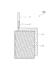
- FIG. 1 shows a configuration of a negative electrode according to an embodiment of the aluminum-air battery of the present invention.
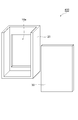
- FIG. 2 shows the configuration of the positive electrode and the oxygen diffusion film according to one embodiment of the aluminum-air battery of the present invention.
- FIG. 3 shows the structure of the laminate according to one embodiment of the aluminum air battery of the present invention.
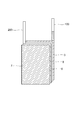
- FIG. 4 shows a configuration of a container according to an embodiment of the aluminum air battery of the present invention.
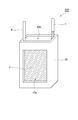
- FIG. 5 is an external view showing an embodiment of the aluminum air battery of the present invention.
- the aluminum alloy constituting the negative electrode of the present invention (hereinafter sometimes referred to as an aluminum alloy or an alloy) has a magnesium content of 0.0001 to 8% by weight.
- the magnesium content in the alloy is preferably 0.01 to 8% by weight, more preferably 1 to 8% by weight, and 2 to 4% by weight. Even more preferred.
- the alloy satisfies at least one condition selected from the group consisting of the following (A) and (B).
- the iron content is 0.0001 to 0.03% by weight (preferably 0.0001 to 0.005% by weight).
- the silicon content is 0.0001 to 0.02 wt% (preferably 0.0005 to 0.005 wt%).
- the corrosion amount of the aluminum alloy may increase when the negative electrode is impregnated with the electrolyte of the air battery.
- the contents of elements other than Al, Mg, Si and Fe in the alloy are each 0.005% by weight or less, preferably 0.002% by weight or less.
- Other elements are, for example, copper (Cu), titanium (Ti), manganese (Mn), gallium (Ga), nickel (Ni), vanadium (V), and zinc (Zn).
- Cu copper
- Ti titanium
- Mn manganese
- Ga gallium
- Ni nickel
- V vanadium
- Zn zinc
- the copper content is preferably 0.002% by weight or less.
- the amount of corrosion of the aluminum alloy becomes particularly large when the negative electrode is impregnated with the electrolyte of the air battery.
- the total content of elements other than aluminum and magnesium in the alloy is preferably 0.1% by weight or less, and more preferably 0.02% by weight. When the total content of elements other than aluminum and magnesium is 0.1% by weight or less, the corrosion resistance to the electrolytic solution is further improved.
- the alloy can include intermetallic compound particles (hereinafter sometimes referred to as particles) in the alloy matrix.
- intermetallic compound particles include Al 3 Mg, Mg 2 Si, and Al—Fe.
- Alloy if containing intermetallic particles in the alloy matrix, at the alloy surface, it is the particle size number density of 0.1 [mu] m 2 or more 100 [mu] m 2 less intermetallic particles is 1000 / mm 2 or less Preferably, it is more preferably 500 pieces / mm 2 or less. Similarly, the number density of intermetallic compound particles having a particle size of 100 ⁇ m 2 or more is preferably 10 particles / mm 2 or less.
- the particle size and the number density of particles can be determined based on an optical micrograph obtained by photographing the surface obtained by etching the surface of the aluminum alloy after mirror polishing with an etching solution.
- the etching solution include a 1% by weight aqueous sodium hydroxide solution.
- the particle size is the area occupied by each intermetallic compound particle observed in the optical micrograph.
- the range from the surface of the aluminum alloy to 10 ⁇ m in the depth direction is considered as the alloy surface.
- the number density of the intermetallic compound particles is less than 0.1 [mu] m 2 or more 100 [mu] m 2 particle size is 1000 / mm 2 or less, the corrosion resistance of the alloy is further improved. Furthermore, when the number density of intermetallic compound particles having a particle size exceeding 100 ⁇ m 2 is 10 particles / mm 2 or less, the corrosion resistance of the alloy is further improved.
- the occupation area ratio of the intermetallic compound particles is preferably 0.5% or less per unit area of the alloy surface, more preferably 0.2% or less, and even more preferably 0.1% or less. It is.
- the occupied area ratio represents the total value of the particle sizes of the individual particles observed in the optical micrograph, that is, the ratio of the total area occupied by the individual particles to the area of the aluminum alloy.
- the alloy in the present invention melts high-purity aluminum (purity: 99.999% or more) at about 680 to 800 ° C., and inserts a predetermined amount of magnesium (purity: 99.99% or more) into the molten aluminum.
- the molten alloy can be obtained by a method including a step of removing hydrogen gas and non-metallic inclusions from the molten alloy. Examples of the removing step include vacuum treatment of molten alloy. The vacuum treatment is usually performed at about 700 ° C. to about 800 ° C. for about 1 hour to about 10 hours and under a vacuum degree of 0.1 to 100 Pa.
- a process of blowing flux, inert gas or chlorine gas into the molten alloy can also be used.
- the molten alloy cleaned in the removing step is usually cast in a mold to obtain an ingot.
- An ingot is obtained by pouring a molten alloy at 680 to 800 ° C. into an iron or graphite mold heated to 50 to 200 ° C.
- the ingot is subjected to a solution treatment.
- the solution treatment the ingot is heated from room temperature to about 430 ° C. at a rate of about 50 ° C./hour and held for about 10 hours, and subsequently heated to about 500 ° C. at a rate of about 50 ° C./hour. And holding for about 10 hours and then cooling from about 500 ° C. to about 200 ° C. at a rate of about 300 ° C./hour.
- the solution-treated ingot can be cut and used as a negative electrode.
- a material obtained by rolling, extruding, or forging an ingot has a higher 0.2% proof stress and is easily used for a negative electrode.
- Examples of the ingot rolling method include a method of processing the ingot into a plate material by hot rolling and cold rolling.
- the hot rolling is repeatedly performed up to the target thickness of the ingot under conditions of a temperature of 350 to 450 ° C. and a one-pass processing rate of 2 to 20%.
- An annealing treatment is usually performed after hot rolling and before cold rolling.
- the hot-rolled plate material may be heated to 350 to 450 ° C. and allowed to cool immediately after being heated, or may be allowed to cool after being held for about 1 to 5 hours. This treatment softens the material and provides a favorable state for cold rolling.
- Cold rolling is repeated, for example, at a temperature lower than the recrystallization temperature of the aluminum alloy, usually from room temperature to 80 ° C., under the condition of a 1-pass processing rate of 1 to 10% until the desired thickness is achieved.
- a temperature lower than the recrystallization temperature of the aluminum alloy usually from room temperature to 80 ° C.
- a 1-pass processing rate of 1 to 10% until the desired thickness is achieved.
- a lead wire is connected to the aluminum alloy. Since the lead wire is connected to the alloy, the discharge current can be efficiently taken out from the negative electrode in the aluminum-air battery.
- the material of the lead wire connected to the aluminum alloy may be a conductive material.
- the material include one or more metals selected from the group consisting of aluminum, nickel, chromium, iron, and titanium, or alloys containing the metals. It is preferable that the lead wire has a noble potential as compared with the aluminum alloy. If the lead wire is noble compared with the aluminum alloy, the lead wire exists until the end of the discharge of the aluminum air battery, and the discharge current can be efficiently taken out from the negative electrode.
- the aluminum content is preferably 99.8% by weight or less. If the aluminum content is 99.8% by weight or less, corrosion due to a potential difference occurring at the connection between the aluminum alloy and the lead wire is suppressed even when the lead wire contacts the electrolyte of the air battery during power generation. be able to. As a result, in the aluminum air battery, the discharge current can be efficiently taken out from the negative electrode.
- the aluminum air battery of the present invention has the negative electrode of the present invention.
- the negative electrode, a separator, a positive electrode having a catalyst layer and a current collector, and a film capable of diffusing oxygen (hereinafter also referred to as an oxygen diffusion film) are laminated in this order.
- a laminated body and an electrolyte are laminated in this order.
- the negative electrode of the present invention As the negative electrode, the negative electrode of the present invention described above is used.
- FIG. 1 shows a configuration of a negative electrode according to an embodiment of the aluminum air battery of the present invention.
- a negative electrode 100 shown in FIG. 1 has an aluminum alloy 3, and an external connection terminal (lead wire) 1 is connected to an end of the aluminum alloy 3.
- an external connection terminal (lead wire) 1 is connected to an end of the aluminum alloy 3.
- one surface of the aluminum alloy 3 that is not in contact with the electrolytic solution and a part of the lead wire 1 are covered with the imide tape 2.
- the lead wire (negative electrode lead wire) 1 the lead wire material described above can be used.
- the shape of the negative electrode include a plate shape, a mesh shape, a porous plate shape, and a sponge shape.
- one surface of the aluminum alloy 3 that does not contact the electrolyte and a part of the lead wire 1 are covered with the imide tape 2, but the imide tape 2 may or may not be present.
- one surface of the aluminum alloy that does not come into contact with the electrolyte and a part of the lead wire are coated with a material such as imide tape that cannot transmit ions involved in the battery reaction. It is preferable.
- the separator is not particularly limited as long as it is an insulating material that can move an electrolyte, and examples thereof include a nonwoven fabric or a porous film made of a resin such as polyolefin or fluororesin.
- a resin such as polyolefin or fluororesin.
- Specific examples of the resin include polyethylene, polypropylene, polytetrafluoroethylene, and polyvinylidene fluoride.
- the separator may be hydrophilized. Examples of the resin in this case include hydrophilicity-treated polyethylene, polypropylene, polytetrafluoroethylene, and polyvinylidene fluoride.
- FIG. 2 shows the configuration of the positive electrode and the oxygen diffusion film according to one embodiment of the aluminum-air battery of the present invention.
- a positive electrode 200 shown in FIG. 2 has a current collector 5 and a catalyst layer (positive electrode catalyst layer) 6 formed on the current collector 5, and an external connection terminal (lead) is provided at the end of the current collector 5. Line) 4 is connected.
- An oxygen diffusion film 7 described later is laminated on the positive electrode 200.
- the current collector 5 may be any conductive material, such as a metal made of nickel, chromium, iron, titanium or an alloy containing the metal, preferably nickel or stainless steel (iron-nickel-chromium alloy). .
- a metal made of nickel, chromium, iron, titanium or an alloy containing the metal preferably nickel or stainless steel (iron-nickel-chromium alloy).
- Examples of the shape include a mesh and a perforated plate.
- the lead wire (positive electrode lead wire) 4 may be any conductive material, for example, one or more metals selected from the group consisting of nickel, chromium, iron and titanium, or an alloy containing the metal, preferably nickel, Stainless steel is mentioned.
- the catalyst layer 6 in the positive electrode 200 has a catalyst.
- the catalyst layer 6 preferably includes a conductive agent and a binder that adheres these to the current collector 5.
- the catalyst in the positive electrode 200 may be any material that can reduce oxygen.
- carbon materials such as activated carbon, non-oxide materials such as platinum and iridium; manganese oxides such as manganese dioxide, iridium oxides, titanium, Examples thereof include iridium oxides containing one or more metals selected from the group consisting of tantalum, niobium, tungsten and zirconium, and oxide materials such as composite oxides having a perovskite structure represented by ABO 3 .
- a catalyst layer containing manganese dioxide or platinum can be mentioned.
- a preferred embodiment of the catalyst layer 6 includes a composite oxide having a perovskite structure represented by ABO 3 , wherein A represents at least two elements selected from the group consisting of La, Sr and Ca, and B represents Mn And a catalyst layer representing at least one element selected from the group consisting of Fe, Cr and Co.
- Platinum is more preferable because of its high catalytic activity for oxygen reduction.
- the composite oxide having the perovskite structure is preferable because it can store and release oxygen. Thereby, an aluminum air battery can be used also as a secondary battery.
- the conductive agent in the positive electrode 200 may be any material that can improve the conductivity of the catalyst layer (positive electrode catalyst layer) 6, and specific examples thereof include carbon materials such as acetylene black and ketjen black.
- the binder in the positive electrode may be any one that is difficult to dissolve in the electrolyte solution used, such as polytetrafluoroethylene (PTFE), tetrafluoroethylene / perfluoroalkyl vinyl ether copolymer, tetrafluoroethylene / hexafluoropropylene copolymer.
- PTFE polytetrafluoroethylene
- Fluorine resins such as polymers, tetrafluoroethylene / ethylene copolymers, polyvinylidene fluoride, polychlorotrifluoroethylene, and chlorotrifluoroethylene / ethylene copolymers are preferred.
- the oxygen diffusion film 7 may be a film that can suitably transmit oxygen in the air, and examples thereof include a nonwoven fabric or a porous film made of a resin such as polyolefin or fluororesin. Specific examples of the resin include resins such as polyethylene, polypropylene, polytetrafluoroethylene, and polyvinylidene fluoride. As shown in FIG. 2, the oxygen diffusion film 7 is laminated on the positive electrode 200, and oxygen in the air is supplied to the positive electrode 200 through the oxygen diffusion film 7.
- FIG. 3 shows the structure of the laminate according to one embodiment of the aluminum air battery of the present invention.
- a laminated body 300 shown in FIG. 3 is obtained by laminating a negative electrode 100, a separator 8, a positive electrode 200, and an oxygen diffusion film 7 in this order.
- the laminate 300 is obtained by laminating the negative electrode 100, the separator 8, the positive electrode 200, and the oxygen diffusion film 7 in this order.
- the electrolyte is usually used as an electrolytic solution dissolved in an aqueous solvent or a non-aqueous solvent, and is in contact with the negative electrode 100, the separator 8, and the positive electrode 200.
- the electrolytic solution is preferably an aqueous solution in which NaOH, KOH, or NH 4 Cl as an electrolyte is dissolved.
- concentration of NaOH, KOH or NH 4 Cl in the aqueous solution is preferably 1 to 99% by weight, more preferably 5 to 60% by weight, and even more preferably 5 to 40% by weight.
- the container accommodates a laminate in which a negative electrode, a separator, a positive electrode, and an oxygen diffusion film are laminated, and an electrolyte (electrolytic solution).
- electrolyte electrolytic solution
- the material of the container include resins such as polystyrene, polyethylene, polypropylene, polyvinyl chloride, and ABS; a negative electrode, a positive electrode, and a metal that hardly reacts with an electrolyte.
- FIG. 4 shows a configuration of a container according to an embodiment of the aluminum air battery of the present invention.
- a container 400 shown in FIG. 4 includes a container body 20 and a lid member 30 in which an opening 10a is formed.
- FIG. 5 is an external view showing an embodiment of the aluminum air battery of the present invention.
- An aluminum-air battery 500 shown in FIG. 5 is arranged such that the laminate 300 is placed on the container body 20 so that an oxygen diffusion film (hereinafter, sometimes referred to as “oxygen permeable film”) 7 is in close contact with the opening 10a.
- the lid member 30 has a structure bonded to the container body 20.
- the aluminum air battery 500 includes an electrolyte inside a container formed from the container body 20 and the lid member 30.
- the aluminum air battery 500 for example, after the laminate 300 is disposed on the container body 20 so that the oxygen permeable membrane 7 is in close contact with the opening 10a, the lid member 30 is adhered to the container body 20 with an adhesive or the like, It can manufacture by pouring electrolyte (electrolyte) from the opening part 10b. In order to prevent leakage of the electrolyte, it is preferable to seal the periphery of the opening 10a and the oxygen permeable membrane with an epoxy resin adhesive or the like.
- oxygen in the air can be supplied to the positive electrode through the oxygen permeable membrane 7 from the opening 10a formed in the container.
- the physical properties were measured as follows. (Aluminum alloy component analysis) Using an emission spectroscopic analyzer (model: ARL-4460, manufactured by Thermo Fisher Scientific), Mg, Si, Fe, Cu, Ti, Mn, Ga, Ni, V, and Zn in the aluminum alloy were quantified. These elements can be quantified more precisely by a glow discharge mass spectrometer.
- Rolling rate It calculated by the following formula from the cross-sectional area (S 0 ) of the aluminum alloy before processing and the cross-sectional area (S) of the aluminum alloy after processing.
- Intermetallic compound particle size, particle number density, occupation area ratio on the aluminum alloy surface The surface of the aluminum alloy was mirror-polished, and the polished surface was etched by immersing in a 1 wt% sodium hydroxide aqueous solution at 20 ° C. for 60 seconds, followed by washing with water. The surface was then photographed using an optical microscope. The particle size of the intermetallic compound particles, the number density of the particles (number per unit area), and the occupied area ratio were determined from an optical micrograph at a photographing magnification of 200 times. It should be noted that particles having a size of less than 0.1 ⁇ m 2 that are difficult to identify with an optical micrograph are not counted.
- the strength of the aluminum alloy was determined by a 0.2% offset method using INSTRON 8802 for a JIS No. 5 test piece, using a test speed of 20 mm / min.
- a test piece (length 40 mm, width 40 mm, thickness 0.5 mm) was immersed in sulfuric acid (concentration 1 mol / L, temperature 80 ° C.). After immersion, 2 hours, 8 hours, and 24 hours elapsed, the eluted Al and Mg were measured. The eluted Al and Mg were quantified by inductively coupled plasma optical emission spectrometry (ICP-AES).
- ICP-AES inductively coupled plasma optical emission spectrometry
- the ingot was solution treated under the following conditions.
- the ingot is heated from room temperature (25 ° C.) to 430 ° C. at a rate of 50 ° C./hour, held at 430 ° C. for 10 hours, and subsequently heated to 500 ° C. at a rate of 50 ° C./hour, at 500 ° C. It was kept for 10 hours, and then cooled from 500 ° C. to 200 ° C. at a rate of 300 ° C./hour.
- the electrode potential of sample 1 using high-purity aluminum is ⁇ 1.66 V
- the electrode potential of samples 2 and 3 in which Mg is added to high-purity aluminum is ⁇ 1.9 to It can be seen that the electrode potential is ⁇ 2.0V.
- separator As a separator, a porous film (length 43 ⁇ width 33 mm, thickness 0.1 mm) made of polytetrafluoroethylene subjected to hydrophilic treatment was used.
- the catalyst layer was composed of acetylene black as a conductive agent, electrolytic MnO 2 as a catalyst for promoting oxygen reduction, and PTFE powder as a binder.
- the weight ratio of acetylene black: electrolytic MnO 2 : PTFE was 10: 10: 1, and a catalyst layer 4 having a length of 40 mm ⁇ width of 30 mm and a thickness of 0.3 mm was formed.
- Nickel ribbon terminal 5 (length 50 mm ⁇ width 3 mm ⁇ thickness 0.20 mm) as a lead wire for external connection at the end of a current collector 3 (length 40 mm ⁇ width 30 mm ⁇ thickness 0.1 mm) made of stainless steel mesh ) Connected.
- the catalyst layer was brought into contact with the current collector to obtain a positive electrode.
- a water-repellent PTFE sheet (length 40 mm ⁇ width 30 mm ⁇ thickness 0.1 mm) was placed on the positive electrode and pressed to laminate an oxygen diffusion film on the positive electrode.
- the aluminum air battery 1 was produced by injecting the electrolytic solution 1 from the opening 10b (see FIG. 5).
- Example 1 Manufacture of aluminum air battery 2
- An aluminum air battery 2 was produced in the same manner as in Comparative Example 1 except that the negative electrode of the aluminum air battery 1 was replaced with the negative electrode 2 made of the sample 2, and a discharge test was performed.
- the discharge capacity per weight of the aluminum alloy of the negative electrode was 2400 mAh / g.
- the average discharge voltage was 1.45V.
- Example 2 Manufacture of aluminum air battery 3
- An aluminum air battery 3 was produced in the same manner as in Comparative Example 1 except that the negative electrode of the aluminum air battery 1 was replaced with the negative electrode 3 made of the sample 3, and a discharge test was performed.
- the discharge capacity per weight of the aluminum alloy of the negative electrode was 2500 mAh / g.
- the average discharge voltage was 1.45V.
- Example 3 Manufacture of aluminum air battery 12
- An aluminum air battery 12 was produced in the same manner as in Comparative Example 1 except that the negative electrode of the aluminum air battery 1 was replaced with the negative electrode 12 made of the sample 12, and a discharge test was performed.
- the discharge capacity per weight of the aluminum alloy of the negative electrode was 2650 mAh / g.
- the average discharge voltage was 1.45V.
- Example 4 Manufacture of aluminum air battery 13
- An aluminum air battery 13 was produced in the same manner as in Comparative Example 1 except that the negative electrode of the aluminum air battery 1 was replaced with the negative electrode 13 made of the sample 13, and a discharge test was performed.
- the discharge capacity per weight of the negative electrode aluminum alloy was 2730 mAh / g.
- the average discharge voltage was 1.45V.
- Example 5 Manufacture of aluminum air battery 14
- An aluminum air battery 14 was produced in the same manner as in Comparative Example 1 except that the negative electrode of the aluminum air battery 1 was replaced with the negative electrode 14 made of the sample 14, and a discharge test was performed.
- the discharge capacity per weight of the aluminum alloy of the negative electrode was 2680 mAh / g.
- the average discharge voltage was 1.45V.
- Example 6 Manufacture of aluminum air battery 15
- An aluminum air battery 15 was produced in the same manner as in Comparative Example 1 except that the negative electrode of the aluminum air battery 1 was replaced with the negative electrode 15 made of the sample 15, and a discharge test was performed.
- the discharge capacity per weight of the negative electrode aluminum alloy was 2710 mAh / g.
- the average discharge voltage was 1.43V.
- Example 7 Manufacture of aluminum air battery 16
- An aluminum air battery 16 was produced in the same manner as in Comparative Example 1 except that the negative electrode of the aluminum air battery 1 was replaced with the negative electrode 16 made of the sample 16, and a discharge test was performed.
- the discharge capacity per weight of the aluminum alloy of the negative electrode was 2690 mAh / g.
- the average discharge voltage was 1.43V.
- Example 8 Manufacture of aluminum air battery 17
- An aluminum air battery 17 was produced in the same manner as in Comparative Example 1 except that the negative electrode of the aluminum air battery 1 was replaced with the negative electrode 17 made of the sample 17, and a discharge test was performed.
- the discharge capacity per weight of the aluminum alloy of the negative electrode was 2800 mAh / g.
- the average discharge voltage was 1.39V.
- Example 9 Manufacture of aluminum air battery 18
- An aluminum air battery 18 was produced in the same manner as in Comparative Example 1 except that the negative electrode of the aluminum air battery 1 was replaced with the negative electrode 18 made of the sample 18, and a discharge test was performed.
- the discharge capacity per weight of the aluminum alloy of the negative electrode was 2640 mAh / g.
- the average discharge voltage was 1.38V.
- Example 10 Manufacture of aluminum air battery 202
- An aluminum air battery 202 was produced in the same manner as in Comparative Example 1 except that the negative electrode of the aluminum air battery 1 was replaced with the negative electrode 2 made of the sample 2 and the electrolytic solution 1 was replaced with the electrolytic solution 2, and a discharge test was performed.
- the discharge capacity per weight of the aluminum alloy of the negative electrode was 2480 mAh / g.
- the average discharge voltage was 1.45V.
- Comparative Example 2 Manufacture of aluminum air battery 8
- An aluminum air battery 8 was produced in the same manner as in Comparative Example 1 except that the negative electrode of the aluminum air battery 1 was replaced with the negative electrode 8 made of the sample 8, and a discharge test was performed.
- the discharge capacity per weight of the aluminum alloy of the negative electrode was 700 mAh / g.
- the average discharge voltage was 1.20V.
- Comparative Example 3 Manufacture of aluminum air battery 9
- An aluminum air battery 9 was produced in the same manner as in Comparative Example 1 except that the negative electrode of the aluminum air battery 1 was replaced with the negative electrode 9 made of the sample 9, and a discharge test was performed.
- the discharge capacity per weight of the aluminum alloy of the negative electrode was 1000 mAh / g.
- the average discharge voltage was 1.30V.
- Comparative Example 4 (Aluminum air battery 10) An aluminum air battery 10 was produced in the same manner as in Comparative Example 1 except that the negative electrode of the aluminum air battery 1 was replaced with the negative electrode 10 made of the sample 10, and a discharge test was performed. As a result, the discharge capacity per weight of the negative electrode aluminum alloy was 900 mAh / g. The average discharge voltage was 1.30V.
- Comparative Example 5 (Aluminum air battery 11) An aluminum air battery 11 was produced and subjected to a discharge test in the same manner as in Comparative Example 1 except that the negative electrode of the aluminum air battery 1 was replaced with the negative electrode 11 made of the sample 11. As a result, the discharge capacity per weight of the aluminum alloy of the negative electrode was 1250 mAh / g. The average discharge voltage was 1.25V.
- Comparative Example 6 Manufacture of aluminum air battery 802
- An aluminum air battery 802 was produced in the same manner as in Comparative Example 1 except that the negative electrode of the aluminum air battery 1 was replaced with the negative electrode 8 made of the sample 8 and the electrolytic solution 1 was replaced with the electrolytic solution 2, and a discharge test was performed.
- the discharge capacity per weight of the aluminum alloy of the negative electrode was 1050 mAh / g.
- the average discharge voltage was 1.20V.
- an aluminum air battery having a high average discharge voltage can be obtained.
- the air battery can be suitably used particularly for applications requiring a high voltage, that is, for driving motors of automobiles and electric tools, and the present invention is extremely useful industrially.
- SYMBOLS 1,4 External connection terminal (lead wire), 2 ... Imido tape, 3 ... Aluminum alloy, 5 ... Current collector, 6 ... Catalyst layer (positive electrode catalyst layer), 7 ... Oxygen diffusion film (oxygen permeable film), 8 ... Separator, 10a, 10b ... opening, 20 ... container body, 30 ... lid member, 100 ... negative electrode, 200 ... positive electrode, 300 ... laminate, 400 ... container, 500 ... aluminum air battery.
Landscapes
- Chemical & Material Sciences (AREA)
- Engineering & Computer Science (AREA)
- Physics & Mathematics (AREA)
- Chemical Kinetics & Catalysis (AREA)
- Electrochemistry (AREA)
- General Chemical & Material Sciences (AREA)
- Thermal Sciences (AREA)
- Crystallography & Structural Chemistry (AREA)
- Materials Engineering (AREA)
- Mechanical Engineering (AREA)
- Metallurgy (AREA)
- Organic Chemistry (AREA)
- Manufacturing & Machinery (AREA)
- Hybrid Cells (AREA)
Priority Applications (4)
| Application Number | Priority Date | Filing Date | Title |
|---|---|---|---|
| US13/580,908 US8574774B2 (en) | 2010-02-25 | 2011-02-18 | Negative electrode and aluminum air cell |
| EP11747265A EP2541670A1 (en) | 2010-02-25 | 2011-02-18 | Negative electrode and aluminum air cell |
| CN201180010891.3A CN102771005B (zh) | 2010-02-25 | 2011-02-18 | 负极及铝空气电池 |
| KR1020127024310A KR20130009785A (ko) | 2010-02-25 | 2011-02-18 | 부극 및 알루미늄 공기 전지 |
Applications Claiming Priority (2)
| Application Number | Priority Date | Filing Date | Title |
|---|---|---|---|
| JP2010-040916 | 2010-02-25 | ||
| JP2010040916 | 2010-02-25 |
Publications (1)
| Publication Number | Publication Date |
|---|---|
| WO2011105301A1 true WO2011105301A1 (ja) | 2011-09-01 |
Family
ID=44506713
Family Applications (1)
| Application Number | Title | Priority Date | Filing Date |
|---|---|---|---|
| PCT/JP2011/053556 WO2011105301A1 (ja) | 2010-02-25 | 2011-02-18 | 負極及びアルミニウム空気電池 |
Country Status (6)
Cited By (3)
| Publication number | Priority date | Publication date | Assignee | Title |
|---|---|---|---|---|
| JP2014139878A (ja) * | 2013-01-21 | 2014-07-31 | Nissan Motor Co Ltd | アルミニウム−空気電池 |
| US20150162620A1 (en) * | 2013-12-06 | 2015-06-11 | Industrial Technology Research Institute | Air battery and air electrode thereof |
| JP6442630B1 (ja) * | 2018-01-24 | 2018-12-19 | 住友化学株式会社 | 非水電解液二次電池用負極活物質、負極及び電池 |
Families Citing this family (11)
| Publication number | Priority date | Publication date | Assignee | Title |
|---|---|---|---|---|
| TWI487166B (zh) * | 2012-12-18 | 2015-06-01 | Ind Tech Res Inst | 一次鋁空氣電池 |
| KR101506787B1 (ko) * | 2013-06-07 | 2015-03-27 | 성균관대학교산학협력단 | 알루미늄-공기 전지용 알루미늄 합금 양극 및 이를 포함하는 알루미늄-공기 전지 |
| CN103700868B (zh) * | 2014-01-15 | 2015-12-09 | 湖南桑顿新能源有限公司 | 一种镁铝合金空气电池及其催化层的制备方法 |
| DE102014208047A1 (de) * | 2014-04-29 | 2015-10-29 | Mahle International Gmbh | Anode und Elektrolyt für eine Metall-Luft-Batterie |
| JP6344079B2 (ja) * | 2014-06-19 | 2018-06-20 | 日産自動車株式会社 | 金属空気電池用負極及び金属空気電池 |
| JP6281532B2 (ja) * | 2015-07-13 | 2018-02-21 | トヨタ自動車株式会社 | 金属空気電池用電解液、及び、金属空気電池 |
| JP6281544B2 (ja) | 2015-09-10 | 2018-02-21 | トヨタ自動車株式会社 | 金属空気電池用電解液、及び、金属空気電池 |
| CN106191571B (zh) * | 2016-08-16 | 2018-07-03 | 中国科学院宁波材料技术与工程研究所 | 铝合金电极材料、其制备方法及其应用 |
| CN108808007A (zh) * | 2018-06-01 | 2018-11-13 | 安徽工业大学 | 一种高铁含量的铝空气电池阳极材料的制备方法 |
| KR20210062025A (ko) * | 2018-10-10 | 2021-05-28 | 스미또모 가가꾸 가부시키가이샤 | 비수 전해액 이차 전지용 부극 활물질, 부극, 전지 및 알루미늄 클래드 금속 적층체 |
| TW202520523A (zh) * | 2023-11-10 | 2025-05-16 | 亞福儲能股份有限公司 | 鋁電池及其製造方法 |
Citations (5)
| Publication number | Priority date | Publication date | Assignee | Title |
|---|---|---|---|---|
| JPS6274041A (ja) * | 1985-07-26 | 1987-04-04 | アルカン・インタ−ナシヨナル・リミテツド | 電気化学的に活性なアルミニウム合金 |
| US4942100A (en) | 1988-08-09 | 1990-07-17 | Alcan International Limited | Aluminium batteries |
| JPH06179936A (ja) | 1992-12-15 | 1994-06-28 | Sumitomo Light Metal Ind Ltd | アルミニウム電池用負極材料 |
| JP2004319464A (ja) * | 2003-03-28 | 2004-11-11 | Toshiba Corp | 空気電池 |
| JP2006147442A (ja) * | 2004-11-24 | 2006-06-08 | Matsushita Electric Ind Co Ltd | アルミニウム空気電池 |
Family Cites Families (8)
| Publication number | Priority date | Publication date | Assignee | Title |
|---|---|---|---|---|
| JP4025150B2 (ja) * | 2001-08-29 | 2007-12-19 | 松下電器産業株式会社 | 発電セルの駆動方法 |
| US20040241537A1 (en) * | 2003-03-28 | 2004-12-02 | Tetsuo Okuyama | Air battery |
| US7892674B2 (en) * | 2005-09-09 | 2011-02-22 | Kabushiki Kaisha Toshiba | Nonaqueous electrolyte secondary battery and battery module |
| JP2008091248A (ja) | 2006-10-03 | 2008-04-17 | Toyota Central R&D Labs Inc | 大容量二次電池 |
| JP2009032400A (ja) * | 2007-07-24 | 2009-02-12 | Toyota Motor Corp | 空気電池システム |
| JP4473908B2 (ja) * | 2007-12-27 | 2010-06-02 | 株式会社神戸製鋼所 | 熱交換器用アルミニウム合金クラッド材、および、その製造方法 |
| US20090260531A1 (en) * | 2008-04-18 | 2009-10-22 | Fujifilm Corporation | Aluminum alloy plate for lithographic printing plate, lithographic printing plate support, presensitized plate, method of manufacturing aluminum alloy plate for lithographic printing plate and method of manufacturing lithographic printing plate support |
| JP2011174159A (ja) * | 2010-02-25 | 2011-09-08 | Sumitomo Chemical Co Ltd | アルミニウム合金 |
-
2011
- 2011-01-31 JP JP2011018535A patent/JP5701627B2/ja active Active
- 2011-02-18 KR KR1020127024310A patent/KR20130009785A/ko not_active Withdrawn
- 2011-02-18 WO PCT/JP2011/053556 patent/WO2011105301A1/ja active Application Filing
- 2011-02-18 US US13/580,908 patent/US8574774B2/en active Active
- 2011-02-18 CN CN201180010891.3A patent/CN102771005B/zh active Active
- 2011-02-18 EP EP11747265A patent/EP2541670A1/en not_active Withdrawn
Patent Citations (5)
| Publication number | Priority date | Publication date | Assignee | Title |
|---|---|---|---|---|
| JPS6274041A (ja) * | 1985-07-26 | 1987-04-04 | アルカン・インタ−ナシヨナル・リミテツド | 電気化学的に活性なアルミニウム合金 |
| US4942100A (en) | 1988-08-09 | 1990-07-17 | Alcan International Limited | Aluminium batteries |
| JPH06179936A (ja) | 1992-12-15 | 1994-06-28 | Sumitomo Light Metal Ind Ltd | アルミニウム電池用負極材料 |
| JP2004319464A (ja) * | 2003-03-28 | 2004-11-11 | Toshiba Corp | 空気電池 |
| JP2006147442A (ja) * | 2004-11-24 | 2006-06-08 | Matsushita Electric Ind Co Ltd | アルミニウム空気電池 |
Cited By (5)
| Publication number | Priority date | Publication date | Assignee | Title |
|---|---|---|---|---|
| JP2014139878A (ja) * | 2013-01-21 | 2014-07-31 | Nissan Motor Co Ltd | アルミニウム−空気電池 |
| US20150162620A1 (en) * | 2013-12-06 | 2015-06-11 | Industrial Technology Research Institute | Air battery and air electrode thereof |
| JP6442630B1 (ja) * | 2018-01-24 | 2018-12-19 | 住友化学株式会社 | 非水電解液二次電池用負極活物質、負極及び電池 |
| WO2019146231A1 (ja) * | 2018-01-24 | 2019-08-01 | 住友化学株式会社 | 非水電解液二次電池用負極活物質、負極及び電池 |
| CN111630694A (zh) * | 2018-01-24 | 2020-09-04 | 住友化学株式会社 | 非水电解液二次电池用负极活性物质、负极以及电池 |
Also Published As
| Publication number | Publication date |
|---|---|
| KR20130009785A (ko) | 2013-01-23 |
| CN102771005B (zh) | 2015-07-29 |
| US20120328963A1 (en) | 2012-12-27 |
| US8574774B2 (en) | 2013-11-05 |
| EP2541670A1 (en) | 2013-01-02 |
| CN102771005A (zh) | 2012-11-07 |
| JP5701627B2 (ja) | 2015-04-15 |
| JP2011198752A (ja) | 2011-10-06 |
Similar Documents
| Publication | Publication Date | Title |
|---|---|---|
| WO2011105301A1 (ja) | 負極及びアルミニウム空気電池 | |
| JP6993337B2 (ja) | マグネシウム-リチウム合金及びマグネシウム空気電池 | |
| WO2012098815A1 (ja) | アルミニウム空気電池 | |
| JP2013247064A (ja) | アルミニウム空気電池 | |
| JP4491208B2 (ja) | 電池缶およびその製造方法ならびに電池 | |
| JP6290520B1 (ja) | マグネシウム−リチウム合金及びマグネシウム空気電池 | |
| JP3933573B2 (ja) | リチウムイオン電池の集電体用アルミニウム箔、リチウムイオン電池の集電体およびリチウムイオン電池 | |
| JP5334485B2 (ja) | リチウムイオン二次電池用集電体および負極材料 | |
| EP2628812A1 (en) | Hydrogen storage alloy, electrode, nickel-metal hydride rechargeable battery and method for producing hydrogen storage alloy | |
| JPWO2020075616A1 (ja) | 非水電解液二次電池用負極活物質、負極、電池及びアルミニウムクラッド金属積層体 | |
| JP2012015025A (ja) | アルミニウム空気電池 | |
| WO2007145175A1 (ja) | 接点部品用または電池部品用材料と、それを用いた電池 | |
| JP2009009778A (ja) | リチウムイオン電池の正極板及びその製造方法、ならびに、それを用いたリチウムイオン電池 | |
| JP2002304998A (ja) | 少なくとも1つのリチウム介在電極を有するガルバーニ電気素子 | |
| EP2713426B1 (en) | Nickel-metal hydride storage battery | |
| US12206128B2 (en) | Sheet-type cell and method for manufacturing same | |
| JP5436825B2 (ja) | アルカリ蓄電池用の水素吸蔵合金粉末、その製造方法及びアルカリ蓄電池 | |
| JP4867145B2 (ja) | 非水電解液電池 | |
| KR20220166270A (ko) | 리튬 이차 전지의 제조 방법 및 리튬 이차 전지의 충전 방법 | |
| JP2007087704A (ja) | 非水電解液二次電池 | |
| JP2013165018A (ja) | 非水電解質二次電池ケース用鋼材 | |
| KR102208834B1 (ko) | 마그네슘 공기전지 | |
| JP2001167749A (ja) | 電池用セパレータ及びその製造装置並びにアルカリ電池 | |
| CN115954439A (zh) | 参比电极的制备方法以及参比电极 | |
| JP5393647B2 (ja) | 金属酸素電池 |
Legal Events
| Date | Code | Title | Description |
|---|---|---|---|
| WWE | Wipo information: entry into national phase |
Ref document number: 201180010891.3 Country of ref document: CN |
|
| 121 | Ep: the epo has been informed by wipo that ep was designated in this application |
Ref document number: 11747265 Country of ref document: EP Kind code of ref document: A1 |
|
| WWE | Wipo information: entry into national phase |
Ref document number: 13580908 Country of ref document: US |
|
| NENP | Non-entry into the national phase |
Ref country code: DE |
|
| WWE | Wipo information: entry into national phase |
Ref document number: 2011747265 Country of ref document: EP |
|
| ENP | Entry into the national phase |
Ref document number: 20127024310 Country of ref document: KR Kind code of ref document: A |
|
| WWE | Wipo information: entry into national phase |
Ref document number: 8088/CHENP/2012 Country of ref document: IN |