WO2011105301A1 - Negative electrode and aluminum air cell - Google Patents
Negative electrode and aluminum air cell Download PDFInfo
- Publication number
- WO2011105301A1 WO2011105301A1 PCT/JP2011/053556 JP2011053556W WO2011105301A1 WO 2011105301 A1 WO2011105301 A1 WO 2011105301A1 JP 2011053556 W JP2011053556 W JP 2011053556W WO 2011105301 A1 WO2011105301 A1 WO 2011105301A1
- Authority
- WO
- WIPO (PCT)
- Prior art keywords
- aluminum
- negative electrode
- alloy
- air battery
- less
- Prior art date
Links
Images

Classifications
-
- H—ELECTRICITY
- H01—ELECTRIC ELEMENTS
- H01M—PROCESSES OR MEANS, e.g. BATTERIES, FOR THE DIRECT CONVERSION OF CHEMICAL ENERGY INTO ELECTRICAL ENERGY
- H01M12/00—Hybrid cells; Manufacture thereof
- H01M12/04—Hybrid cells; Manufacture thereof composed of a half-cell of the fuel-cell type and of a half-cell of the primary-cell type
- H01M12/06—Hybrid cells; Manufacture thereof composed of a half-cell of the fuel-cell type and of a half-cell of the primary-cell type with one metallic and one gaseous electrode
- H01M12/065—Hybrid cells; Manufacture thereof composed of a half-cell of the fuel-cell type and of a half-cell of the primary-cell type with one metallic and one gaseous electrode with plate-like electrodes or stacks of plate-like electrodes
-
- C—CHEMISTRY; METALLURGY
- C21—METALLURGY OF IRON
- C21D—MODIFYING THE PHYSICAL STRUCTURE OF FERROUS METALS; GENERAL DEVICES FOR HEAT TREATMENT OF FERROUS OR NON-FERROUS METALS OR ALLOYS; MAKING METAL MALLEABLE, e.g. BY DECARBURISATION OR TEMPERING
- C21D1/00—General methods or devices for heat treatment, e.g. annealing, hardening, quenching or tempering
- C21D1/06—Surface hardening
-
- C—CHEMISTRY; METALLURGY
- C22—METALLURGY; FERROUS OR NON-FERROUS ALLOYS; TREATMENT OF ALLOYS OR NON-FERROUS METALS
- C22F—CHANGING THE PHYSICAL STRUCTURE OF NON-FERROUS METALS AND NON-FERROUS ALLOYS
- C22F1/00—Changing the physical structure of non-ferrous metals or alloys by heat treatment or by hot or cold working
- C22F1/04—Changing the physical structure of non-ferrous metals or alloys by heat treatment or by hot or cold working of aluminium or alloys based thereon
-
- H—ELECTRICITY
- H01—ELECTRIC ELEMENTS
- H01M—PROCESSES OR MEANS, e.g. BATTERIES, FOR THE DIRECT CONVERSION OF CHEMICAL ENERGY INTO ELECTRICAL ENERGY
- H01M12/00—Hybrid cells; Manufacture thereof
- H01M12/04—Hybrid cells; Manufacture thereof composed of a half-cell of the fuel-cell type and of a half-cell of the primary-cell type
- H01M12/06—Hybrid cells; Manufacture thereof composed of a half-cell of the fuel-cell type and of a half-cell of the primary-cell type with one metallic and one gaseous electrode
-
- H—ELECTRICITY
- H01—ELECTRIC ELEMENTS
- H01M—PROCESSES OR MEANS, e.g. BATTERIES, FOR THE DIRECT CONVERSION OF CHEMICAL ENERGY INTO ELECTRICAL ENERGY
- H01M4/00—Electrodes
- H01M4/02—Electrodes composed of, or comprising, active material
- H01M4/36—Selection of substances as active materials, active masses, active liquids
- H01M4/38—Selection of substances as active materials, active masses, active liquids of elements or alloys
- H01M4/46—Alloys based on magnesium or aluminium
-
- H—ELECTRICITY
- H01—ELECTRIC ELEMENTS
- H01M—PROCESSES OR MEANS, e.g. BATTERIES, FOR THE DIRECT CONVERSION OF CHEMICAL ENERGY INTO ELECTRICAL ENERGY
- H01M4/00—Electrodes
- H01M4/02—Electrodes composed of, or comprising, active material
- H01M2004/026—Electrodes composed of, or comprising, active material characterised by the polarity
- H01M2004/027—Negative electrodes
-
- H—ELECTRICITY
- H01—ELECTRIC ELEMENTS
- H01M—PROCESSES OR MEANS, e.g. BATTERIES, FOR THE DIRECT CONVERSION OF CHEMICAL ENERGY INTO ELECTRICAL ENERGY
- H01M4/00—Electrodes
- H01M4/86—Inert electrodes with catalytic activity, e.g. for fuel cells
- H01M2004/8678—Inert electrodes with catalytic activity, e.g. for fuel cells characterised by the polarity
- H01M2004/8689—Positive electrodes
-
- H—ELECTRICITY
- H01—ELECTRIC ELEMENTS
- H01M—PROCESSES OR MEANS, e.g. BATTERIES, FOR THE DIRECT CONVERSION OF CHEMICAL ENERGY INTO ELECTRICAL ENERGY
- H01M4/00—Electrodes
- H01M4/02—Electrodes composed of, or comprising, active material
- H01M4/36—Selection of substances as active materials, active masses, active liquids
- H01M4/38—Selection of substances as active materials, active masses, active liquids of elements or alloys
- H01M4/46—Alloys based on magnesium or aluminium
- H01M4/463—Aluminium based
-
- H—ELECTRICITY
- H01—ELECTRIC ELEMENTS
- H01M—PROCESSES OR MEANS, e.g. BATTERIES, FOR THE DIRECT CONVERSION OF CHEMICAL ENERGY INTO ELECTRICAL ENERGY
- H01M4/00—Electrodes
- H01M4/86—Inert electrodes with catalytic activity, e.g. for fuel cells
- H01M4/90—Selection of catalytic material
- H01M4/9016—Oxides, hydroxides or oxygenated metallic salts
-
- H—ELECTRICITY
- H01—ELECTRIC ELEMENTS
- H01M—PROCESSES OR MEANS, e.g. BATTERIES, FOR THE DIRECT CONVERSION OF CHEMICAL ENERGY INTO ELECTRICAL ENERGY
- H01M4/00—Electrodes
- H01M4/86—Inert electrodes with catalytic activity, e.g. for fuel cells
- H01M4/90—Selection of catalytic material
- H01M4/92—Metals of platinum group
-
- Y—GENERAL TAGGING OF NEW TECHNOLOGICAL DEVELOPMENTS; GENERAL TAGGING OF CROSS-SECTIONAL TECHNOLOGIES SPANNING OVER SEVERAL SECTIONS OF THE IPC; TECHNICAL SUBJECTS COVERED BY FORMER USPC CROSS-REFERENCE ART COLLECTIONS [XRACs] AND DIGESTS
- Y02—TECHNOLOGIES OR APPLICATIONS FOR MITIGATION OR ADAPTATION AGAINST CLIMATE CHANGE
- Y02E—REDUCTION OF GREENHOUSE GAS [GHG] EMISSIONS, RELATED TO ENERGY GENERATION, TRANSMISSION OR DISTRIBUTION
- Y02E60/00—Enabling technologies; Technologies with a potential or indirect contribution to GHG emissions mitigation
- Y02E60/10—Energy storage using batteries
Definitions
- the present invention relates to a negative electrode and an aluminum air battery, and more particularly to a negative electrode and an aluminum air battery used in an aluminum air battery.
- An air battery in which oxygen in the air is used as an active material can increase the energy density.
- the air battery is expected as a battery that can be applied to various uses such as for electric vehicles.
- Examples of the air battery include an aluminum air battery.
- Patent Document 1 discloses an aluminum air battery having an alloy composed of aluminum, magnesium and manganese as a negative electrode
- Patent Document 2 discloses an aluminum air battery having an alloy composed of aluminum, magnesium, tin and manganese as a negative electrode.
- the conventional aluminum alloy used for the negative electrode of an aluminum air battery has corrosion resistance that is not appropriate for an electrolytic solution containing acid or alkali. Therefore, the conventional aluminum air battery has an insufficient average discharge voltage.
- the present invention provides the following. ⁇ 1> Having an aluminum alloy,
- the alloy has a magnesium content of 0.0001 wt% or more and 8 wt% or less,
- the alloy satisfies at least one condition selected from the group consisting of the following (A) and (B),
- (A) The iron content is 0.0001 wt% or more and 0.03 wt% or less
- the silicon content is 0.0001 wt% or more and 0.02 wt% or less
- a negative electrode in which the content of elements other than aluminum, magnesium, silicon and iron in the alloy is 0.005% by weight or less.
- ⁇ 2> The negative electrode of ⁇ 1>, wherein the total content of elements other than aluminum and magnesium in the alloy is 0.1% by weight or less.
- the alloy includes intermetallic compound particles in an alloy matrix, On the alloy surface, The number density of intermetallic compound particles having a particle size of 0.1 ⁇ m 2 or more and less than 100 ⁇ m 2 is 1000 / mm 2 or less, The number density of intermetallic compound particles having a particle size of 100 ⁇ m 2 or more is 10 particles / mm 2 or less, and The negative electrode according to ⁇ 1> or ⁇ 2>, wherein the occupation area ratio of the intermetallic compound particles is 0.5% or less per unit area of the alloy surface.
- ⁇ 4> The negative electrode according to any one of ⁇ 1> to ⁇ 3>, wherein the alloy is a rolled material.
- ⁇ 5> The negative electrode according to any one of ⁇ 1> to ⁇ 4>, wherein a lead wire is connected to the alloy.
- ⁇ 6> The negative electrode of ⁇ 5>, wherein the lead wire has a noble potential compared to the alloy.
- Aluminum air according to ⁇ 8> having a laminate in which the negative electrode, a separator, a positive electrode having a catalyst layer and a current collector, and a film capable of diffusing oxygen are laminated in this order, and an electrolyte battery.
- the catalyst layer in the positive electrode includes a composite oxide having a perovskite structure represented by ABO 3 , A represents at least two elements selected from the group consisting of La, Sr and Ca, and B represents Mn ⁇ 9>
- An aluminum air battery representing at least one element selected from the group consisting of Fe, Cr and Co.
- an aluminum air battery having a high average discharge voltage and a negative electrode suitable for the air battery can be obtained.
- the air battery can be suitably used for applications requiring a high voltage, for example, for driving motors of automobiles and electric tools.
- the present invention is extremely useful industrially.
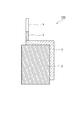
- FIG. 1 shows a configuration of a negative electrode according to an embodiment of the aluminum-air battery of the present invention.
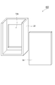
- FIG. 2 shows the configuration of the positive electrode and the oxygen diffusion film according to one embodiment of the aluminum-air battery of the present invention.
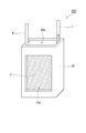
- FIG. 3 shows the structure of the laminate according to one embodiment of the aluminum air battery of the present invention.
- FIG. 4 shows a configuration of a container according to an embodiment of the aluminum air battery of the present invention.
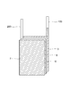
- FIG. 5 is an external view showing an embodiment of the aluminum air battery of the present invention.
- the aluminum alloy constituting the negative electrode of the present invention (hereinafter sometimes referred to as an aluminum alloy or an alloy) has a magnesium content of 0.0001 to 8% by weight.
- the magnesium content in the alloy is preferably 0.01 to 8% by weight, more preferably 1 to 8% by weight, and 2 to 4% by weight. Even more preferred.
- the alloy satisfies at least one condition selected from the group consisting of the following (A) and (B).
- the iron content is 0.0001 to 0.03% by weight (preferably 0.0001 to 0.005% by weight).
- the silicon content is 0.0001 to 0.02 wt% (preferably 0.0005 to 0.005 wt%).
- the corrosion amount of the aluminum alloy may increase when the negative electrode is impregnated with the electrolyte of the air battery.
- the contents of elements other than Al, Mg, Si and Fe in the alloy are each 0.005% by weight or less, preferably 0.002% by weight or less.
- Other elements are, for example, copper (Cu), titanium (Ti), manganese (Mn), gallium (Ga), nickel (Ni), vanadium (V), and zinc (Zn).
- Cu copper
- Ti titanium
- Mn manganese
- Ga gallium
- Ni nickel
- V vanadium
- Zn zinc
- the copper content is preferably 0.002% by weight or less.
- the amount of corrosion of the aluminum alloy becomes particularly large when the negative electrode is impregnated with the electrolyte of the air battery.
- the total content of elements other than aluminum and magnesium in the alloy is preferably 0.1% by weight or less, and more preferably 0.02% by weight. When the total content of elements other than aluminum and magnesium is 0.1% by weight or less, the corrosion resistance to the electrolytic solution is further improved.
- the alloy can include intermetallic compound particles (hereinafter sometimes referred to as particles) in the alloy matrix.
- intermetallic compound particles include Al 3 Mg, Mg 2 Si, and Al—Fe.
- Alloy if containing intermetallic particles in the alloy matrix, at the alloy surface, it is the particle size number density of 0.1 [mu] m 2 or more 100 [mu] m 2 less intermetallic particles is 1000 / mm 2 or less Preferably, it is more preferably 500 pieces / mm 2 or less. Similarly, the number density of intermetallic compound particles having a particle size of 100 ⁇ m 2 or more is preferably 10 particles / mm 2 or less.
- the particle size and the number density of particles can be determined based on an optical micrograph obtained by photographing the surface obtained by etching the surface of the aluminum alloy after mirror polishing with an etching solution.
- the etching solution include a 1% by weight aqueous sodium hydroxide solution.
- the particle size is the area occupied by each intermetallic compound particle observed in the optical micrograph.
- the range from the surface of the aluminum alloy to 10 ⁇ m in the depth direction is considered as the alloy surface.
- the number density of the intermetallic compound particles is less than 0.1 [mu] m 2 or more 100 [mu] m 2 particle size is 1000 / mm 2 or less, the corrosion resistance of the alloy is further improved. Furthermore, when the number density of intermetallic compound particles having a particle size exceeding 100 ⁇ m 2 is 10 particles / mm 2 or less, the corrosion resistance of the alloy is further improved.
- the occupation area ratio of the intermetallic compound particles is preferably 0.5% or less per unit area of the alloy surface, more preferably 0.2% or less, and even more preferably 0.1% or less. It is.
- the occupied area ratio represents the total value of the particle sizes of the individual particles observed in the optical micrograph, that is, the ratio of the total area occupied by the individual particles to the area of the aluminum alloy.
- the alloy in the present invention melts high-purity aluminum (purity: 99.999% or more) at about 680 to 800 ° C., and inserts a predetermined amount of magnesium (purity: 99.99% or more) into the molten aluminum.
- the molten alloy can be obtained by a method including a step of removing hydrogen gas and non-metallic inclusions from the molten alloy. Examples of the removing step include vacuum treatment of molten alloy. The vacuum treatment is usually performed at about 700 ° C. to about 800 ° C. for about 1 hour to about 10 hours and under a vacuum degree of 0.1 to 100 Pa.
- a process of blowing flux, inert gas or chlorine gas into the molten alloy can also be used.
- the molten alloy cleaned in the removing step is usually cast in a mold to obtain an ingot.
- An ingot is obtained by pouring a molten alloy at 680 to 800 ° C. into an iron or graphite mold heated to 50 to 200 ° C.
- the ingot is subjected to a solution treatment.
- the solution treatment the ingot is heated from room temperature to about 430 ° C. at a rate of about 50 ° C./hour and held for about 10 hours, and subsequently heated to about 500 ° C. at a rate of about 50 ° C./hour. And holding for about 10 hours and then cooling from about 500 ° C. to about 200 ° C. at a rate of about 300 ° C./hour.
- the solution-treated ingot can be cut and used as a negative electrode.
- a material obtained by rolling, extruding, or forging an ingot has a higher 0.2% proof stress and is easily used for a negative electrode.
- Examples of the ingot rolling method include a method of processing the ingot into a plate material by hot rolling and cold rolling.
- the hot rolling is repeatedly performed up to the target thickness of the ingot under conditions of a temperature of 350 to 450 ° C. and a one-pass processing rate of 2 to 20%.
- An annealing treatment is usually performed after hot rolling and before cold rolling.
- the hot-rolled plate material may be heated to 350 to 450 ° C. and allowed to cool immediately after being heated, or may be allowed to cool after being held for about 1 to 5 hours. This treatment softens the material and provides a favorable state for cold rolling.
- Cold rolling is repeated, for example, at a temperature lower than the recrystallization temperature of the aluminum alloy, usually from room temperature to 80 ° C., under the condition of a 1-pass processing rate of 1 to 10% until the desired thickness is achieved.
- a temperature lower than the recrystallization temperature of the aluminum alloy usually from room temperature to 80 ° C.
- a 1-pass processing rate of 1 to 10% until the desired thickness is achieved.
- a lead wire is connected to the aluminum alloy. Since the lead wire is connected to the alloy, the discharge current can be efficiently taken out from the negative electrode in the aluminum-air battery.
- the material of the lead wire connected to the aluminum alloy may be a conductive material.
- the material include one or more metals selected from the group consisting of aluminum, nickel, chromium, iron, and titanium, or alloys containing the metals. It is preferable that the lead wire has a noble potential as compared with the aluminum alloy. If the lead wire is noble compared with the aluminum alloy, the lead wire exists until the end of the discharge of the aluminum air battery, and the discharge current can be efficiently taken out from the negative electrode.
- the aluminum content is preferably 99.8% by weight or less. If the aluminum content is 99.8% by weight or less, corrosion due to a potential difference occurring at the connection between the aluminum alloy and the lead wire is suppressed even when the lead wire contacts the electrolyte of the air battery during power generation. be able to. As a result, in the aluminum air battery, the discharge current can be efficiently taken out from the negative electrode.
- the aluminum air battery of the present invention has the negative electrode of the present invention.
- the negative electrode, a separator, a positive electrode having a catalyst layer and a current collector, and a film capable of diffusing oxygen (hereinafter also referred to as an oxygen diffusion film) are laminated in this order.
- a laminated body and an electrolyte are laminated in this order.
- the negative electrode of the present invention As the negative electrode, the negative electrode of the present invention described above is used.
- FIG. 1 shows a configuration of a negative electrode according to an embodiment of the aluminum air battery of the present invention.
- a negative electrode 100 shown in FIG. 1 has an aluminum alloy 3, and an external connection terminal (lead wire) 1 is connected to an end of the aluminum alloy 3.
- an external connection terminal (lead wire) 1 is connected to an end of the aluminum alloy 3.
- one surface of the aluminum alloy 3 that is not in contact with the electrolytic solution and a part of the lead wire 1 are covered with the imide tape 2.
- the lead wire (negative electrode lead wire) 1 the lead wire material described above can be used.
- the shape of the negative electrode include a plate shape, a mesh shape, a porous plate shape, and a sponge shape.
- one surface of the aluminum alloy 3 that does not contact the electrolyte and a part of the lead wire 1 are covered with the imide tape 2, but the imide tape 2 may or may not be present.
- one surface of the aluminum alloy that does not come into contact with the electrolyte and a part of the lead wire are coated with a material such as imide tape that cannot transmit ions involved in the battery reaction. It is preferable.
- the separator is not particularly limited as long as it is an insulating material that can move an electrolyte, and examples thereof include a nonwoven fabric or a porous film made of a resin such as polyolefin or fluororesin.
- a resin such as polyolefin or fluororesin.
- Specific examples of the resin include polyethylene, polypropylene, polytetrafluoroethylene, and polyvinylidene fluoride.
- the separator may be hydrophilized. Examples of the resin in this case include hydrophilicity-treated polyethylene, polypropylene, polytetrafluoroethylene, and polyvinylidene fluoride.
- FIG. 2 shows the configuration of the positive electrode and the oxygen diffusion film according to one embodiment of the aluminum-air battery of the present invention.
- a positive electrode 200 shown in FIG. 2 has a current collector 5 and a catalyst layer (positive electrode catalyst layer) 6 formed on the current collector 5, and an external connection terminal (lead) is provided at the end of the current collector 5. Line) 4 is connected.
- An oxygen diffusion film 7 described later is laminated on the positive electrode 200.
- the current collector 5 may be any conductive material, such as a metal made of nickel, chromium, iron, titanium or an alloy containing the metal, preferably nickel or stainless steel (iron-nickel-chromium alloy). .
- a metal made of nickel, chromium, iron, titanium or an alloy containing the metal preferably nickel or stainless steel (iron-nickel-chromium alloy).
- Examples of the shape include a mesh and a perforated plate.
- the lead wire (positive electrode lead wire) 4 may be any conductive material, for example, one or more metals selected from the group consisting of nickel, chromium, iron and titanium, or an alloy containing the metal, preferably nickel, Stainless steel is mentioned.
- the catalyst layer 6 in the positive electrode 200 has a catalyst.
- the catalyst layer 6 preferably includes a conductive agent and a binder that adheres these to the current collector 5.
- the catalyst in the positive electrode 200 may be any material that can reduce oxygen.
- carbon materials such as activated carbon, non-oxide materials such as platinum and iridium; manganese oxides such as manganese dioxide, iridium oxides, titanium, Examples thereof include iridium oxides containing one or more metals selected from the group consisting of tantalum, niobium, tungsten and zirconium, and oxide materials such as composite oxides having a perovskite structure represented by ABO 3 .
- a catalyst layer containing manganese dioxide or platinum can be mentioned.
- a preferred embodiment of the catalyst layer 6 includes a composite oxide having a perovskite structure represented by ABO 3 , wherein A represents at least two elements selected from the group consisting of La, Sr and Ca, and B represents Mn And a catalyst layer representing at least one element selected from the group consisting of Fe, Cr and Co.
- Platinum is more preferable because of its high catalytic activity for oxygen reduction.
- the composite oxide having the perovskite structure is preferable because it can store and release oxygen. Thereby, an aluminum air battery can be used also as a secondary battery.
- the conductive agent in the positive electrode 200 may be any material that can improve the conductivity of the catalyst layer (positive electrode catalyst layer) 6, and specific examples thereof include carbon materials such as acetylene black and ketjen black.
- the binder in the positive electrode may be any one that is difficult to dissolve in the electrolyte solution used, such as polytetrafluoroethylene (PTFE), tetrafluoroethylene / perfluoroalkyl vinyl ether copolymer, tetrafluoroethylene / hexafluoropropylene copolymer.
- PTFE polytetrafluoroethylene
- Fluorine resins such as polymers, tetrafluoroethylene / ethylene copolymers, polyvinylidene fluoride, polychlorotrifluoroethylene, and chlorotrifluoroethylene / ethylene copolymers are preferred.
- the oxygen diffusion film 7 may be a film that can suitably transmit oxygen in the air, and examples thereof include a nonwoven fabric or a porous film made of a resin such as polyolefin or fluororesin. Specific examples of the resin include resins such as polyethylene, polypropylene, polytetrafluoroethylene, and polyvinylidene fluoride. As shown in FIG. 2, the oxygen diffusion film 7 is laminated on the positive electrode 200, and oxygen in the air is supplied to the positive electrode 200 through the oxygen diffusion film 7.
- FIG. 3 shows the structure of the laminate according to one embodiment of the aluminum air battery of the present invention.
- a laminated body 300 shown in FIG. 3 is obtained by laminating a negative electrode 100, a separator 8, a positive electrode 200, and an oxygen diffusion film 7 in this order.
- the laminate 300 is obtained by laminating the negative electrode 100, the separator 8, the positive electrode 200, and the oxygen diffusion film 7 in this order.
- the electrolyte is usually used as an electrolytic solution dissolved in an aqueous solvent or a non-aqueous solvent, and is in contact with the negative electrode 100, the separator 8, and the positive electrode 200.
- the electrolytic solution is preferably an aqueous solution in which NaOH, KOH, or NH 4 Cl as an electrolyte is dissolved.
- concentration of NaOH, KOH or NH 4 Cl in the aqueous solution is preferably 1 to 99% by weight, more preferably 5 to 60% by weight, and even more preferably 5 to 40% by weight.
- the container accommodates a laminate in which a negative electrode, a separator, a positive electrode, and an oxygen diffusion film are laminated, and an electrolyte (electrolytic solution).
- electrolyte electrolytic solution
- the material of the container include resins such as polystyrene, polyethylene, polypropylene, polyvinyl chloride, and ABS; a negative electrode, a positive electrode, and a metal that hardly reacts with an electrolyte.
- FIG. 4 shows a configuration of a container according to an embodiment of the aluminum air battery of the present invention.
- a container 400 shown in FIG. 4 includes a container body 20 and a lid member 30 in which an opening 10a is formed.
- FIG. 5 is an external view showing an embodiment of the aluminum air battery of the present invention.
- An aluminum-air battery 500 shown in FIG. 5 is arranged such that the laminate 300 is placed on the container body 20 so that an oxygen diffusion film (hereinafter, sometimes referred to as “oxygen permeable film”) 7 is in close contact with the opening 10a.
- the lid member 30 has a structure bonded to the container body 20.
- the aluminum air battery 500 includes an electrolyte inside a container formed from the container body 20 and the lid member 30.
- the aluminum air battery 500 for example, after the laminate 300 is disposed on the container body 20 so that the oxygen permeable membrane 7 is in close contact with the opening 10a, the lid member 30 is adhered to the container body 20 with an adhesive or the like, It can manufacture by pouring electrolyte (electrolyte) from the opening part 10b. In order to prevent leakage of the electrolyte, it is preferable to seal the periphery of the opening 10a and the oxygen permeable membrane with an epoxy resin adhesive or the like.
- oxygen in the air can be supplied to the positive electrode through the oxygen permeable membrane 7 from the opening 10a formed in the container.
- the physical properties were measured as follows. (Aluminum alloy component analysis) Using an emission spectroscopic analyzer (model: ARL-4460, manufactured by Thermo Fisher Scientific), Mg, Si, Fe, Cu, Ti, Mn, Ga, Ni, V, and Zn in the aluminum alloy were quantified. These elements can be quantified more precisely by a glow discharge mass spectrometer.
- Rolling rate It calculated by the following formula from the cross-sectional area (S 0 ) of the aluminum alloy before processing and the cross-sectional area (S) of the aluminum alloy after processing.
- Intermetallic compound particle size, particle number density, occupation area ratio on the aluminum alloy surface The surface of the aluminum alloy was mirror-polished, and the polished surface was etched by immersing in a 1 wt% sodium hydroxide aqueous solution at 20 ° C. for 60 seconds, followed by washing with water. The surface was then photographed using an optical microscope. The particle size of the intermetallic compound particles, the number density of the particles (number per unit area), and the occupied area ratio were determined from an optical micrograph at a photographing magnification of 200 times. It should be noted that particles having a size of less than 0.1 ⁇ m 2 that are difficult to identify with an optical micrograph are not counted.
- the strength of the aluminum alloy was determined by a 0.2% offset method using INSTRON 8802 for a JIS No. 5 test piece, using a test speed of 20 mm / min.
- a test piece (length 40 mm, width 40 mm, thickness 0.5 mm) was immersed in sulfuric acid (concentration 1 mol / L, temperature 80 ° C.). After immersion, 2 hours, 8 hours, and 24 hours elapsed, the eluted Al and Mg were measured. The eluted Al and Mg were quantified by inductively coupled plasma optical emission spectrometry (ICP-AES).
- ICP-AES inductively coupled plasma optical emission spectrometry
- the ingot was solution treated under the following conditions.
- the ingot is heated from room temperature (25 ° C.) to 430 ° C. at a rate of 50 ° C./hour, held at 430 ° C. for 10 hours, and subsequently heated to 500 ° C. at a rate of 50 ° C./hour, at 500 ° C. It was kept for 10 hours, and then cooled from 500 ° C. to 200 ° C. at a rate of 300 ° C./hour.
- the electrode potential of sample 1 using high-purity aluminum is ⁇ 1.66 V
- the electrode potential of samples 2 and 3 in which Mg is added to high-purity aluminum is ⁇ 1.9 to It can be seen that the electrode potential is ⁇ 2.0V.
- separator As a separator, a porous film (length 43 ⁇ width 33 mm, thickness 0.1 mm) made of polytetrafluoroethylene subjected to hydrophilic treatment was used.
- the catalyst layer was composed of acetylene black as a conductive agent, electrolytic MnO 2 as a catalyst for promoting oxygen reduction, and PTFE powder as a binder.
- the weight ratio of acetylene black: electrolytic MnO 2 : PTFE was 10: 10: 1, and a catalyst layer 4 having a length of 40 mm ⁇ width of 30 mm and a thickness of 0.3 mm was formed.
- Nickel ribbon terminal 5 (length 50 mm ⁇ width 3 mm ⁇ thickness 0.20 mm) as a lead wire for external connection at the end of a current collector 3 (length 40 mm ⁇ width 30 mm ⁇ thickness 0.1 mm) made of stainless steel mesh ) Connected.
- the catalyst layer was brought into contact with the current collector to obtain a positive electrode.
- a water-repellent PTFE sheet (length 40 mm ⁇ width 30 mm ⁇ thickness 0.1 mm) was placed on the positive electrode and pressed to laminate an oxygen diffusion film on the positive electrode.
- the aluminum air battery 1 was produced by injecting the electrolytic solution 1 from the opening 10b (see FIG. 5).
- Example 1 Manufacture of aluminum air battery 2
- An aluminum air battery 2 was produced in the same manner as in Comparative Example 1 except that the negative electrode of the aluminum air battery 1 was replaced with the negative electrode 2 made of the sample 2, and a discharge test was performed.
- the discharge capacity per weight of the aluminum alloy of the negative electrode was 2400 mAh / g.
- the average discharge voltage was 1.45V.
- Example 2 Manufacture of aluminum air battery 3
- An aluminum air battery 3 was produced in the same manner as in Comparative Example 1 except that the negative electrode of the aluminum air battery 1 was replaced with the negative electrode 3 made of the sample 3, and a discharge test was performed.
- the discharge capacity per weight of the aluminum alloy of the negative electrode was 2500 mAh / g.
- the average discharge voltage was 1.45V.
- Example 3 Manufacture of aluminum air battery 12
- An aluminum air battery 12 was produced in the same manner as in Comparative Example 1 except that the negative electrode of the aluminum air battery 1 was replaced with the negative electrode 12 made of the sample 12, and a discharge test was performed.
- the discharge capacity per weight of the aluminum alloy of the negative electrode was 2650 mAh / g.
- the average discharge voltage was 1.45V.
- Example 4 Manufacture of aluminum air battery 13
- An aluminum air battery 13 was produced in the same manner as in Comparative Example 1 except that the negative electrode of the aluminum air battery 1 was replaced with the negative electrode 13 made of the sample 13, and a discharge test was performed.
- the discharge capacity per weight of the negative electrode aluminum alloy was 2730 mAh / g.
- the average discharge voltage was 1.45V.
- Example 5 Manufacture of aluminum air battery 14
- An aluminum air battery 14 was produced in the same manner as in Comparative Example 1 except that the negative electrode of the aluminum air battery 1 was replaced with the negative electrode 14 made of the sample 14, and a discharge test was performed.
- the discharge capacity per weight of the aluminum alloy of the negative electrode was 2680 mAh / g.
- the average discharge voltage was 1.45V.
- Example 6 Manufacture of aluminum air battery 15
- An aluminum air battery 15 was produced in the same manner as in Comparative Example 1 except that the negative electrode of the aluminum air battery 1 was replaced with the negative electrode 15 made of the sample 15, and a discharge test was performed.
- the discharge capacity per weight of the negative electrode aluminum alloy was 2710 mAh / g.
- the average discharge voltage was 1.43V.
- Example 7 Manufacture of aluminum air battery 16
- An aluminum air battery 16 was produced in the same manner as in Comparative Example 1 except that the negative electrode of the aluminum air battery 1 was replaced with the negative electrode 16 made of the sample 16, and a discharge test was performed.
- the discharge capacity per weight of the aluminum alloy of the negative electrode was 2690 mAh / g.
- the average discharge voltage was 1.43V.
- Example 8 Manufacture of aluminum air battery 17
- An aluminum air battery 17 was produced in the same manner as in Comparative Example 1 except that the negative electrode of the aluminum air battery 1 was replaced with the negative electrode 17 made of the sample 17, and a discharge test was performed.
- the discharge capacity per weight of the aluminum alloy of the negative electrode was 2800 mAh / g.
- the average discharge voltage was 1.39V.
- Example 9 Manufacture of aluminum air battery 18
- An aluminum air battery 18 was produced in the same manner as in Comparative Example 1 except that the negative electrode of the aluminum air battery 1 was replaced with the negative electrode 18 made of the sample 18, and a discharge test was performed.
- the discharge capacity per weight of the aluminum alloy of the negative electrode was 2640 mAh / g.
- the average discharge voltage was 1.38V.
- Example 10 Manufacture of aluminum air battery 202
- An aluminum air battery 202 was produced in the same manner as in Comparative Example 1 except that the negative electrode of the aluminum air battery 1 was replaced with the negative electrode 2 made of the sample 2 and the electrolytic solution 1 was replaced with the electrolytic solution 2, and a discharge test was performed.
- the discharge capacity per weight of the aluminum alloy of the negative electrode was 2480 mAh / g.
- the average discharge voltage was 1.45V.
- Comparative Example 2 Manufacture of aluminum air battery 8
- An aluminum air battery 8 was produced in the same manner as in Comparative Example 1 except that the negative electrode of the aluminum air battery 1 was replaced with the negative electrode 8 made of the sample 8, and a discharge test was performed.
- the discharge capacity per weight of the aluminum alloy of the negative electrode was 700 mAh / g.
- the average discharge voltage was 1.20V.
- Comparative Example 3 Manufacture of aluminum air battery 9
- An aluminum air battery 9 was produced in the same manner as in Comparative Example 1 except that the negative electrode of the aluminum air battery 1 was replaced with the negative electrode 9 made of the sample 9, and a discharge test was performed.
- the discharge capacity per weight of the aluminum alloy of the negative electrode was 1000 mAh / g.
- the average discharge voltage was 1.30V.
- Comparative Example 4 (Aluminum air battery 10) An aluminum air battery 10 was produced in the same manner as in Comparative Example 1 except that the negative electrode of the aluminum air battery 1 was replaced with the negative electrode 10 made of the sample 10, and a discharge test was performed. As a result, the discharge capacity per weight of the negative electrode aluminum alloy was 900 mAh / g. The average discharge voltage was 1.30V.
- Comparative Example 5 (Aluminum air battery 11) An aluminum air battery 11 was produced and subjected to a discharge test in the same manner as in Comparative Example 1 except that the negative electrode of the aluminum air battery 1 was replaced with the negative electrode 11 made of the sample 11. As a result, the discharge capacity per weight of the aluminum alloy of the negative electrode was 1250 mAh / g. The average discharge voltage was 1.25V.
- Comparative Example 6 Manufacture of aluminum air battery 802
- An aluminum air battery 802 was produced in the same manner as in Comparative Example 1 except that the negative electrode of the aluminum air battery 1 was replaced with the negative electrode 8 made of the sample 8 and the electrolytic solution 1 was replaced with the electrolytic solution 2, and a discharge test was performed.
- the discharge capacity per weight of the aluminum alloy of the negative electrode was 1050 mAh / g.
- the average discharge voltage was 1.20V.
- an aluminum air battery having a high average discharge voltage can be obtained.
- the air battery can be suitably used particularly for applications requiring a high voltage, that is, for driving motors of automobiles and electric tools, and the present invention is extremely useful industrially.
- SYMBOLS 1,4 External connection terminal (lead wire), 2 ... Imido tape, 3 ... Aluminum alloy, 5 ... Current collector, 6 ... Catalyst layer (positive electrode catalyst layer), 7 ... Oxygen diffusion film (oxygen permeable film), 8 ... Separator, 10a, 10b ... opening, 20 ... container body, 30 ... lid member, 100 ... negative electrode, 200 ... positive electrode, 300 ... laminate, 400 ... container, 500 ... aluminum air battery.
Abstract
Description
<1> アルミニウム合金を有し、
該合金は、マグネシウム含有量が0.0001重量%以上8重量%以下であり、
該合金は、下記(A)および(B)からなる群より選ばれる少なくとも1つの条件を満たし、
(A) 鉄の含有量が0.0001重量%以上0.03重量%以下である
(B) ケイ素の含有量が0.0001重量%以上0.02重量%以下である
かつ、
該合金におけるアルミニウム、マグネシウム、ケイ素、鉄以外の元素の含有量が、それぞれ0.005重量%以下である負極。 The present invention provides the following.
<1> Having an aluminum alloy,
The alloy has a magnesium content of 0.0001 wt% or more and 8 wt% or less,
The alloy satisfies at least one condition selected from the group consisting of the following (A) and (B),
(A) The iron content is 0.0001 wt% or more and 0.03 wt% or less (B) The silicon content is 0.0001 wt% or more and 0.02 wt% or less, and
A negative electrode in which the content of elements other than aluminum, magnesium, silicon and iron in the alloy is 0.005% by weight or less.
合金表面において、
粒子サイズが0.1μm2以上100μm2未満の金属間化合物粒子の個数密度が、1000個/mm2以下であり、
粒子サイズが100μm2以上の金属間化合物粒子の個数密度が、10個/mm2以下であり、かつ、
金属間化合物粒子の占有面積割合が、合金表面の単位面積当り0.5%以下である<1>または<2>の負極。 <3> The alloy includes intermetallic compound particles in an alloy matrix,
On the alloy surface,
The number density of intermetallic compound particles having a particle size of 0.1 μm 2 or more and less than 100 μm 2 is 1000 / mm 2 or less,
The number density of intermetallic compound particles having a particle size of 100 μm 2 or more is 10 particles / mm 2 or less, and
The negative electrode according to <1> or <2>, wherein the occupation area ratio of the intermetallic compound particles is 0.5% or less per unit area of the alloy surface.
(B)ケイ素含有量が0.0001~0.02重量%(好ましくは0.0005~0.005重量%)である。 (A) The iron content is 0.0001 to 0.03% by weight (preferably 0.0001 to 0.005% by weight).
(B) The silicon content is 0.0001 to 0.02 wt% (preferably 0.0005 to 0.005 wt%).
本発明における合金は、例えば、高純度アルミニウム(純度:99.999%以上)を約680~800℃で溶融し、所定量のマグネシウム(純度:99.99%以上)を溶融アルミニウム中に挿入して合金溶湯を得て、合金溶湯から水素ガスや非金属介在物を除去する工程を含む方法により製造することができる。前記の除去工程としては、例えば、合金溶湯の真空処理が挙げられる。真空処理は、通常、約700℃~約800℃で約1時間~約10時間、真空度0.1~100Paの条件で行われる。前記除去工程として、合金溶湯に、フラックス、不活性ガスまたは塩素ガスを吹き込む処理も利用できる。除去工程で清浄にされた合金溶湯は、通常、鋳型にて鋳造され、鋳塊が得られる。50~200℃に加熱された鉄製または黒鉛製の鋳型に、680~800℃の合金溶湯を流し込む方法により鋳塊が得られる。 (Alloy manufacturing method)
The alloy in the present invention, for example, melts high-purity aluminum (purity: 99.999% or more) at about 680 to 800 ° C., and inserts a predetermined amount of magnesium (purity: 99.99% or more) into the molten aluminum. Thus, the molten alloy can be obtained by a method including a step of removing hydrogen gas and non-metallic inclusions from the molten alloy. Examples of the removing step include vacuum treatment of molten alloy. The vacuum treatment is usually performed at about 700 ° C. to about 800 ° C. for about 1 hour to about 10 hours and under a vacuum degree of 0.1 to 100 Pa. As the removing step, a process of blowing flux, inert gas or chlorine gas into the molten alloy can also be used. The molten alloy cleaned in the removing step is usually cast in a mold to obtain an ingot. An ingot is obtained by pouring a molten alloy at 680 to 800 ° C. into an iron or graphite mold heated to 50 to 200 ° C.
本発明のアルミニウム空気電池は、本発明の負極を有する。本発明のアルミニウム空気電池は、好ましくは、前記負極と、セパレータと、触媒層及び集電体を有する正極と、酸素を拡散可能な膜(以下、酸素拡散膜ともいう。)とがこの順に積層された積層体、及び、電解質を有する。 (Aluminum air battery)
The aluminum air battery of the present invention has the negative electrode of the present invention. In the aluminum-air battery of the present invention, preferably, the negative electrode, a separator, a positive electrode having a catalyst layer and a current collector, and a film capable of diffusing oxygen (hereinafter also referred to as an oxygen diffusion film) are laminated in this order. A laminated body and an electrolyte.
負極としては、上述の本発明の負極が使用される。 (Negative electrode)
As the negative electrode, the negative electrode of the present invention described above is used.
セパレータとしては、電解質の移動が可能な絶縁材料であれば特に限定されず、例えば、ポリオレフィン、フッ素樹脂等の樹脂からなる、不織布または多孔質膜が挙げられる。具体的な樹脂としては、ポリエチレン、ポリプロピレン、ポリテトラフルオロエチレン、ポリフッ化ビニリデン等が挙げられる。電解質が水溶液である場合は、セパレータは親水化されていてもよい。この場合の樹脂として、親水性化処理されたポリエチレン、ポリプロピレン、ポリテトラフルオロエチレン、ポリフッ化ビニリデン等が挙げられる。 (Separator)
The separator is not particularly limited as long as it is an insulating material that can move an electrolyte, and examples thereof include a nonwoven fabric or a porous film made of a resin such as polyolefin or fluororesin. Specific examples of the resin include polyethylene, polypropylene, polytetrafluoroethylene, and polyvinylidene fluoride. When the electrolyte is an aqueous solution, the separator may be hydrophilized. Examples of the resin in this case include hydrophilicity-treated polyethylene, polypropylene, polytetrafluoroethylene, and polyvinylidene fluoride.
図2は本発明のアルミニウム空気電池の一態様に係る正極および酸素拡散膜の構成を示す。図2に示す正極200は、集電体5、及び、集電体5上に形成された触媒層(正極触媒層)6を有し、集電体5の端部には外部接続端子(リード線)4が接続している。正極200には後述する酸素拡散膜7が積層されている。 (Positive electrode)
FIG. 2 shows the configuration of the positive electrode and the oxygen diffusion film according to one embodiment of the aluminum-air battery of the present invention. A
酸素拡散膜7は、空気中の酸素を好適に透過できる膜であればよく、ポリオレフィン、フッ素樹脂等の樹脂からなる、不織布または多孔質膜が挙げられる。樹脂として、具体的には、ポリエチレン、ポリプロピレン、ポリテトラフルオロエチレン、ポリフッ化ビニリデン等の樹脂が挙げられる。酸素拡散膜7は、図2に示すように正極200に積層しており、酸素拡散膜7を介して正極200に空気中の酸素が供給される。 (Oxygen diffusion film 7)
The
図3は本発明のアルミニウム空気電池の一態様に係る積層体の構成を示す。図3に示す積層体300は、負極100と、セパレータ8と、正極200と、酸素拡散膜7と、がこの順に積層されたものである。当該積層体300は、負極100と、セパレータ8と、正極200と、酸素拡散膜7とをこの順に積層することにより得られる。 (Laminate)
FIG. 3 shows the structure of the laminate according to one embodiment of the aluminum air battery of the present invention. A laminated body 300 shown in FIG. 3 is obtained by laminating a
電解質は、通常、水系溶媒または非水系溶媒に溶解された電解液として使用され、負極100、セパレータ8、及び、正極200と接触している。 (Electrolytes)
The electrolyte is usually used as an electrolytic solution dissolved in an aqueous solvent or a non-aqueous solvent, and is in contact with the
容器は、負極と、セパレータと、正極と、酸素拡散膜とが積層された積層体及び電解質(電解液)を収容する。容器の材質としては、例えば、ポリスチレン、ポリエチレン、ポリプロピレン、ポリ塩化ビニル、ABS等の樹脂;負極、正極、電解質と反応し難い金属などが挙げられる。 (container)
The container accommodates a laminate in which a negative electrode, a separator, a positive electrode, and an oxygen diffusion film are laminated, and an electrolyte (electrolytic solution). Examples of the material of the container include resins such as polystyrene, polyethylene, polypropylene, polyvinyl chloride, and ABS; a negative electrode, a positive electrode, and a metal that hardly reacts with an electrolyte.
(アルミニウム合金の成分分析)
発光分光分析装置(型式:ARL-4460、サーモフィッシャーサイエンティフィック社製)を使用し、アルミニウム合金中のMg、Si、Fe、Cu、Ti、Mn、Ga、Ni、V、Znを定量した。なお、これらの元素は、グロー放電質量分析装置によって、より精密に定量することができる。 The physical properties were measured as follows.
(Aluminum alloy component analysis)
Using an emission spectroscopic analyzer (model: ARL-4460, manufactured by Thermo Fisher Scientific), Mg, Si, Fe, Cu, Ti, Mn, Ga, Ni, V, and Zn in the aluminum alloy were quantified. These elements can be quantified more precisely by a glow discharge mass spectrometer.
加工前のアルミニウム合金の断面積(S0)と加工後のアルミニウム合金の断面積(S)から下式により算出した。 (Rolling rate)
It calculated by the following formula from the cross-sectional area (S 0 ) of the aluminum alloy before processing and the cross-sectional area (S) of the aluminum alloy after processing.
アルミニウム合金の表面を鏡面研磨し、研磨後の表面を20℃、1重量%水酸化ナトリウム水溶液に60秒間浸漬することによりエッチングし、水洗した。次いで、光学顕微鏡を使って表面を撮影した。撮影倍率200倍の光学顕微鏡写真により、金属間化合物粒子の粒子サイズ、粒子の個数密度(単位面積当りの個数)及び占有面積割合を決定した。なお、光学顕微鏡写真による識別が困難な0.1μm2未満のサイズの粒子はカウントされていない。 (Intermetallic compound particle size, particle number density, occupation area ratio on the aluminum alloy surface)
The surface of the aluminum alloy was mirror-polished, and the polished surface was etched by immersing in a 1 wt% sodium hydroxide aqueous solution at 20 ° C. for 60 seconds, followed by washing with water. The surface was then photographed using an optical microscope. The particle size of the intermetallic compound particles, the number density of the particles (number per unit area), and the occupied area ratio were determined from an optical micrograph at a photographing magnification of 200 times. It should be noted that particles having a size of less than 0.1 μm 2 that are difficult to identify with an optical micrograph are not counted.
アルミニウム合金の強度は、JIS5号試験片についてINSTRON 8802を使用して、試験速度:20mm/分、0.2%オフセット法により求めた。 (Strength of aluminum alloy (0.2% proof stress))
The strength of the aluminum alloy was determined by a 0.2% offset method using INSTRON 8802 for a JIS No. 5 test piece, using a test speed of 20 mm / min.
試験片(縦40mm、横40mm、厚さ0.5mm)を硫酸(濃度1mol/L、温度80℃)に浸漬した。浸漬後、2時間、8時間、24時間経過後、溶出したAl、Mgを測定した。溶出したAl、Mgは誘導結合プラズマ発光分光分析(ICP-AES)により定量した。 (Corrosion resistance of aluminum alloy)
A test piece (length 40 mm, width 40 mm, thickness 0.5 mm) was immersed in sulfuric acid (
(アルミニウム サンプル1の製造)
高純度アルミニウム(純度:99.999%以上)を750℃で溶融し、アルミニウム溶湯を得た。次に、アルミニウム溶湯を温度750℃で、2時間、真空度50Paの条件で保持して真空処理を行った。真空処理後のアルミニウム溶湯を150℃の鋳鉄鋳型(22mm×150mm×200mm)にて鋳造し、鋳塊を得た。 (Production Example 1)
(Manufacture of aluminum sample 1)
High purity aluminum (purity: 99.999% or more) was melted at 750 ° C. to obtain a molten aluminum. Next, vacuum treatment was performed by holding the molten aluminum at a temperature of 750 ° C. for 2 hours under the condition of a degree of vacuum of 50 Pa. The molten aluminum after vacuum treatment was cast in a cast iron mold (22 mm × 150 mm × 200 mm) at 150 ° C. to obtain an ingot.
(アルミニウム合金 サンプル2の製造)
高純度アルミニウム(純度:99.999%以上)を750℃で溶融し、マグネシウム(純度:99.99%以上)を、合金におけるMg含有量が2.5重量%となるように配合して、溶融アルミニウム中に挿入して、Mg含有量が2.5重量%であるAl-Mg合金溶湯を得た。次に、合金溶湯を温度750℃で、2時間、真空度50Paの条件で保持して真空処理を行った。真空処理後の合金溶湯を150℃の鋳鉄鋳型(22mm×150mm×200mm)にて鋳造し、鋳塊を得た。 (Production Example 2)
(Production of aluminum alloy sample 2)
High purity aluminum (purity: 99.999% or more) is melted at 750 ° C., and magnesium (purity: 99.99% or more) is blended so that the Mg content in the alloy is 2.5% by weight, By inserting into molten aluminum, a molten Al—Mg alloy having an Mg content of 2.5% by weight was obtained. Next, vacuum processing was performed by holding the molten alloy at a temperature of 750 ° C. for 2 hours under a condition of a degree of vacuum of 50 Pa. The molten alloy after vacuum treatment was cast with a cast iron mold (22 mm × 150 mm × 200 mm) at 150 ° C. to obtain an ingot.
(アルミニウム合金 サンプル3の製造)
Mgの含有量が3.8重量%となるように配合したこと以外は製造例2と同様の操作を行い、サンプル3を製造した。サンプル3に含まれる成分の測定結果を表1に示す。 (Production Example 3)
(Production of aluminum alloy sample 3)
(アルミニウム合金 サンプル4の製造)
Mgの含有量が5.0重量%となるように配合すること以外は製造例2と同様の操作を行い、サンプル4を製造する。 (Production Example 4)
(Production of aluminum alloy sample 4)
A
(アルミニウム合金 サンプル5の製造)
Mgの含有量が7.0重量%となるように配合すること以外は製造例2と同様の操作を行い、サンプル5を製造する。 (Production Example 5)
(Production of aluminum alloy sample 5)
(アルミニウム合金 サンプル6の製造)
Mgの含有量が10.0重量%となるように配合すること以外は製造例2と同様の操作を行い、サンプル6を製造する。 (Production Example 6)
(Production of aluminum alloy sample 6)
A
(アルミニウム合金 サンプル7の製造)
Mgの含有量が12.0重量%となるように配合すること以外は製造例2と同様の操作を行い、サンプル7を製造する。 (Production Example 7)
(Manufacture of aluminum alloy sample 7)
(アルミニウム サンプル8の製造)
高純度アルミニウム(純度:99.999%)に代えてアルミニウム(純度:99.8%)を用いた以外は、製造例1と同様の操作を行い、サンプル8を製造した。サンプル8に含まれる成分の測定結果を表1に示す。 (Production Example 8)
(Manufacture of aluminum sample 8)
(アルミニウム合金 サンプル9の製造)
高純度アルミニウム(純度:99.999%)に代えてアルミニウム(純度:99.8%)を用いた以外は、製造例2と同様の操作を行い、サンプル9を製造した。サンプル9に含まれる成分の測定結果を表1に示す。 (Production Example 9)
(Production of aluminum alloy sample 9)
Sample 9 was produced in the same manner as in Production Example 2, except that aluminum (purity: 99.8%) was used instead of high-purity aluminum (purity: 99.999%). Table 1 shows the measurement results of the components contained in Sample 9.
(アルミニウム合金 サンプル10の製造)
高純度アルミニウム(純度:99.999%)に代えてアルミニウム(純度:99.8%)を用い、Mgの含有量が3.7重量%となるように配合したこと以外は製造例2と同様の操作を行い、サンプル10を製造した。サンプル10に含まれる成分の測定結果を表1に示す。 (Production Example 10)
(Manufacture of aluminum alloy sample 10)
Similar to Production Example 2, except that aluminum (purity: 99.8%) was used instead of high-purity aluminum (purity: 99.999%) and the Mg content was 3.7% by weight. The sample 10 was manufactured by performing the above operations. Table 1 shows the measurement results of the components contained in Sample 10.
(アルミニウム合金 サンプル11の製造)
Mgに代えて、Cu(純度:99.99%)を、Cuの含有量が0.5重量%となるように配合したこと以外は製造例2と同様の操作を行い、サンプル11を製造した。サンプル11に含まれる成分の測定結果を表1に示す。 (Production Example 11)
(Manufacture of aluminum alloy sample 11)
Sample 11 was produced in the same manner as in Production Example 2 except that Cu (purity: 99.99%) was blended in place of Mg so that the Cu content was 0.5% by weight. . Table 1 shows the measurement results of the components contained in Sample 11.
(アルミニウム合金 サンプル12の製造)
Mgの含有量が1.5重量%となるように配合したこと以外は製造例2と同様の操作を行い、サンプル12を製造した。サンプル12に含まれる成分の測定結果を表1に示す。 (Production Example 12)
(Manufacture of aluminum alloy sample 12)
Sample 12 was produced in the same manner as in Production Example 2, except that the Mg content was 1.5% by weight. Table 1 shows the measurement results of the components contained in Sample 12.
(アルミニウム合金 サンプル13の製造)
Mgの含有量が1.0重量%となるように配合したこと以外は製造例2と同様の操作を行い、サンプル13を製造した。サンプル13に含まれる成分の測定結果を表1に示す。 (Production Example 13)
(Manufacture of aluminum alloy sample 13)
A sample 13 was produced in the same manner as in Production Example 2 except that the Mg content was 1.0% by weight. Table 1 shows the measurement results of the components contained in Sample 13.
(アルミニウム合金 サンプル14の製造)
Mgの含有量が0.5重量%となるように配合したこと以外は製造例2と同様の操作を行い、サンプル14を製造した。サンプル14に含まれる成分の測定結果を表1に示す。 (Production Example 14)
(Manufacture of aluminum alloy sample 14)
Sample 14 was produced in the same manner as in Production Example 2 except that the Mg content was 0.5% by weight. Table 1 shows the measurement results of the components contained in Sample 14.
(アルミニウム合金 サンプル15の製造)
Mgの含有量が0.25重量%となるように配合したこと以外は製造例2と同様の操作を行い、サンプル15を製造した。サンプル15に含まれる成分の測定結果を表1に示す。 (Production Example 15)
(Manufacture of aluminum alloy sample 15)
A sample 15 was produced in the same manner as in Production Example 2 except that the Mg content was 0.25% by weight. Table 1 shows the measurement results of the components contained in Sample 15.
(アルミニウム合金 サンプル16の製造)
Mgの含有量が0.1重量%となるように配合したこと以外は製造例2と同様の操作を行い、サンプル16を製造した。サンプル16に含まれる成分の測定結果を表1に示す。 (Production Example 16)
(Manufacture of aluminum alloy sample 16)
A sample 16 was produced in the same manner as in Production Example 2 except that the Mg content was 0.1% by weight. Table 1 shows the measurement results of the components contained in Sample 16.
(アルミニウム合金 サンプル17の製造)
Mgの含有量が0.05重量%となるように配合すること以外は製造例2と同様の操作を行い、サンプル17を製造した。サンプル17に含まれる成分の測定結果を表1に示す。 (Production Example 17)
(Manufacture of aluminum alloy sample 17)
A sample 17 was produced in the same manner as in Production Example 2, except that the Mg content was 0.05% by weight. Table 1 shows the measurement results of the components contained in Sample 17.
(アルミニウム合金 サンプル18の製造)
Mgの含有量を0.01重量%となるように配合すること以外は製造例2と同様の操作を行い、サンプル18を製造した。サンプル18に含まれる成分の測定結果を表1に示す。 (Production Example 18)
(Manufacture of aluminum alloy sample 18)
A sample 18 was produced in the same manner as in Production Example 2, except that the Mg content was 0.01% by weight. Table 1 shows the measurement results of the components contained in Sample 18.

水酸化カリウムと純水とを混合することにより、1mol/LのKOH水溶液を製造して、これを電解液1とした。 (Manufacture of electrolytic solution 1)
By mixing potassium hydroxide and pure water, a 1 mol / L KOH aqueous solution was produced.
水酸化ナトリウムと純水とを混合することにより、1mol/LのNaOH水溶液を製造して、これを電解液2とした。 (Manufacture of electrolytic solution 2)
By mixing sodium hydroxide and pure water, a 1 mol / L NaOH aqueous solution was produced, and this was used as the
(自己腐食量の測定)
サンプル1~3、8~18の0.1mmの板材を直径13mmの円板状に切断した。これらを23℃において電解液1である1.0mol/LのKOH水溶液に20分間含浸して、含浸後のアルミニウム合金の乾燥重量及び含浸前のアルミニウム合金の乾燥重量を量ることで、自己腐食量を測定した。結果を表2に示す。 (Measurement Example 1)
(Measurement of self-corrosion)
The 0.1 mm plate materials of

(電極電位の測定)
サンプル1~3、8~18の0.1mmの板材を5×15mmの角板状に切断した。これらを23℃において電解液1に含浸して、飽和カロメル電極を基準として電極電位を測定した。結果を表3に示す。 (Measurement example 2)
(Measurement of electrode potential)
0.1 mm plate materials of

(圧延板の強度(0.2%耐力)の測定)
サンプル2、3、8~10の強度を測定した。結果を表4に示す。 (Measurement Example 3)
(Measurement of strength (0.2% proof stress) of rolled sheet)
The strength of

(アルミニウム合金中の化合物の粒子サイズ、粒子の個数密度、占有面積割合の測定)
サンプル2、3、8~10中の化合物の粒子サイズ、粒子の個数密度(粒子密度)、占有面積割合を測定した。結果を表5、表6に示す。 (Measurement Example 4)
(Measurement of particle size, particle number density, and occupied area ratio of compound in aluminum alloy)
The particle size, particle number density (particle density), and occupied area ratio of the compounds in


(アルミニウム合金の耐食性の測定)
サンプル2、3、8~10の耐食性を測定した。結果を表7に示す。 (Measurement Example 5)
(Measurement of corrosion resistance of aluminum alloy)
The corrosion resistance of

サンプル1~3、8~11を負極として使用したアルミニウム空気電池を製造し、その性能評価を行った。 (Measurement Example 6)
Aluminum-air
(アルミニウム空気電池1の製造)
(負極の作製)
サンプル1を、縦40mm×横30mmに切断し、その後、アルミニウムリード線(純度99.5%、縦50mm×横3mm×厚み0.20mm、電極電位-1.45V)を抵抗溶接機で取り付けることで負極を作製した。抵抗溶接部と抵抗溶接部から伸びたアルミリード線10mmとアルミニウム(縦40mm×横30mm)の片面をイミドテープでマスキングした。 (Comparative Example 1)
(Manufacture of aluminum air battery 1)
(Preparation of negative electrode)
セパレータとしては、親水性処理されたポリテトラフルオロエチレンからなる多孔質膜(縦43×横33mm、厚み0.1mm)を用いた。 (Preparation of separator)
As a separator, a porous film (length 43 × width 33 mm, thickness 0.1 mm) made of polytetrafluoroethylene subjected to hydrophilic treatment was used.
触媒層は、導電剤としてのアセチレンブラックと、酸素の還元を促進する触媒としての電解MnO2と、結着剤としてのPTFE粉末とにより構成された。アセチレンブラック:電解MnO2:PTFEの重量比は10:10:1であり、縦40mm×横30mm、厚み0.3mmの触媒層4を成形した。ステンレスメッシュ製の放電用の集電体3(縦40mm×横30mm×厚み0.1mm)の端部に外部接続用のリード線であるニッケルリボン端子5(縦50mm×横3mm×厚み0.20mm)を接続した。集電体に触媒層を当接し、正極を得た。 (Preparation of positive electrode)
The catalyst layer was composed of acetylene black as a conductive agent, electrolytic MnO 2 as a catalyst for promoting oxygen reduction, and PTFE powder as a binder. The weight ratio of acetylene black: electrolytic MnO 2 : PTFE was 10: 10: 1, and a
上記の正極に撥水性PTFEシート(縦40mm×横30mm×厚み0.1mm)を載置し圧着することで正極に酸素拡散膜を積層した。 (Attaching the oxygen diffusion membrane to the positive electrode)
A water-repellent PTFE sheet (length 40 mm ×
上記のように作製した酸素拡散膜および正極を容器に載置し、セパレータ、サンプル1からなる負極をこの順に積層し、蓋部材で蓋をした。その後、容器開口部10a/酸素拡散膜の周辺部をエポキシ系接着剤でシールした。 (Assembly of battery 1)
The oxygen diffusion film and the positive electrode produced as described above were placed on a container, a separator and a negative electrode made of
(放電試験)
上述のようにして作製したアルミニウム空気電池を、充放電試験機(東洋システム社製、製品名TOSCAT-3000U)に接続し、負極のアルミニウムに対して、10mA/cm2で定電流放電(CC放電)を行い、終止電圧0.5Vでカットオフした。その結果、負極のアルミニウムの重量当りの放電容量は、1500mAh/gであった。平均放電電圧は1.25Vであった。 <Air battery performance evaluation>
(Discharge test)
The aluminum air battery produced as described above was connected to a charge / discharge tester (product name: TOSCAT-3000U, manufactured by Toyo System Co., Ltd.), and was subjected to constant current discharge (CC discharge) at 10 mA / cm 2 with respect to the negative electrode aluminum. ) And cut off at a final voltage of 0.5V. As a result, the discharge capacity per weight of aluminum of the negative electrode was 1500 mAh / g. The average discharge voltage was 1.25V.
(アルミニウム空気電池2の製造)
アルミニウム空気電池1の負極をサンプル2からなる負極2に代えた以外は、比較例1と同様にしてアルミニウム空気電池2を作製し、放電試験を行った。その結果、負極のアルミニウム合金の重量当りの放電容量は、2400mAh/gであった。平均放電電圧は1.45Vであった。 Example 1
(Manufacture of aluminum air battery 2)
An
(アルミニウム空気電池3の製造)
アルミニウム空気電池1の負極をサンプル3からなる負極3に代えた以外は、比較例1と同様にしてアルミニウム空気電池3を作製し、放電試験を行った。その結果、負極のアルミニウム合金の重量当りの放電容量は、2500mAh/gであった。平均放電電圧は1.45Vであった。 (Example 2)
(Manufacture of aluminum air battery 3)
An
(アルミニウム空気電池12の製造)
アルミニウム空気電池1の負極をサンプル12からなる負極12に代えた以外は、比較例1と同様にしてアルミニウム空気電池12を作製し、放電試験を行った。その結果、負極のアルミニウム合金の重量当りの放電容量は、2650mAh/gであった。平均放電電圧は1.45Vであった。 (Example 3)
(Manufacture of aluminum air battery 12)
An aluminum air battery 12 was produced in the same manner as in Comparative Example 1 except that the negative electrode of the
(アルミニウム空気電池13の製造)
アルミニウム空気電池1の負極をサンプル13からなる負極13に代えた以外は、比較例1と同様にしてアルミニウム空気電池13を作製し、放電試験を行った。その結果、負極のアルミニウム合金の重量当りの放電容量は、2730mAh/gであった。平均放電電圧は1.45Vであった。 Example 4
(Manufacture of aluminum air battery 13)
An aluminum air battery 13 was produced in the same manner as in Comparative Example 1 except that the negative electrode of the
(アルミニウム空気電池14の製造)
アルミニウム空気電池1の負極をサンプル14からなる負極14に代えた以外は、比較例1と同様にしてアルミニウム空気電池14を作製し、放電試験を行った。その結果、負極のアルミニウム合金の重量当りの放電容量は、2680mAh/gであった。平均放電電圧は1.45Vであった。 (Example 5)
(Manufacture of aluminum air battery 14)
An aluminum air battery 14 was produced in the same manner as in Comparative Example 1 except that the negative electrode of the
(アルミニウム空気電池15の製造)
アルミニウム空気電池1の負極をサンプル15からなる負極15に代えた以外は、比較例1と同様にしてアルミニウム空気電池15を作製し、放電試験を行った。その結果、負極のアルミニウム合金の重量当りの放電容量は、2710mAh/gであった。平均放電電圧は1.43Vであった。 (Example 6)
(Manufacture of aluminum air battery 15)
An aluminum air battery 15 was produced in the same manner as in Comparative Example 1 except that the negative electrode of the
(アルミニウム空気電池16の製造)
アルミニウム空気電池1の負極をサンプル16からなる負極16に代えた以外は、比較例1と同様にしてアルミニウム空気電池16を作製し、放電試験を行った。その結果、負極のアルミニウム合金の重量当りの放電容量は、2690mAh/gであった。平均放電電圧は1.43Vであった。 (Example 7)
(Manufacture of aluminum air battery 16)
An aluminum air battery 16 was produced in the same manner as in Comparative Example 1 except that the negative electrode of the
(アルミニウム空気電池17の製造)
アルミニウム空気電池1の負極をサンプル17からなる負極17に代える以外は、比較例1と同様にしてアルミニウム空気電池17を作製し、放電試験を行った。その結果、負極のアルミニウム合金の重量当りの放電容量は、2800mAh/gであった。平均放電電圧は1.39Vであった。 (Example 8)
(Manufacture of aluminum air battery 17)
An aluminum air battery 17 was produced in the same manner as in Comparative Example 1 except that the negative electrode of the
(アルミニウム空気電池18の製造)
アルミニウム空気電池1の負極をサンプル18からなる負極18に代える以外は、比較例1と同様にしてアルミニウム空気電池18を作製し、放電試験を行った。その結果、負極のアルミニウム合金の重量当りの放電容量は、2640mAh/gであった。平均放電電圧は1.38Vであった。 Example 9
(Manufacture of aluminum air battery 18)
An aluminum air battery 18 was produced in the same manner as in Comparative Example 1 except that the negative electrode of the
(アルミニウム空気電池202の製造)
アルミニウム空気電池1の負極をサンプル2からなる負極2に代え、電解液1を電解液2に代えた以外は、比較例1と同様にしてアルミニウム空気電池202を作製し、放電試験を行った。その結果、負極のアルミニウム合金の重量当りの放電容量は、2480mAh/gであった。平均放電電圧は1.45Vであった。 (Example 10)
(Manufacture of aluminum air battery 202)
An aluminum air battery 202 was produced in the same manner as in Comparative Example 1 except that the negative electrode of the
(アルミニウム空気電池8の製造)
アルミニウム空気電池1の負極をサンプル8からなる負極8に代えた以外は、比較例1と同様にしてアルミニウム空気電池8を作製し、放電試験を行った。その結果、負極のアルミニウム合金の重量当りの放電容量は、700mAh/gであった。平均放電電圧は1.20Vであった。 (Comparative Example 2)
(Manufacture of aluminum air battery 8)
An
(アルミニウム空気電池9の製造)
アルミニウム空気電池1の負極をサンプル9からなる負極9に代えた以外は、比較例1と同様にしてアルミニウム空気電池9を作製し、放電試験を行った。その結果、負極のアルミニウム合金の重量当りの放電容量は、1000mAh/gであった。平均放電電圧は1.30Vであった。 (Comparative Example 3)
(Manufacture of aluminum air battery 9)
An aluminum air battery 9 was produced in the same manner as in Comparative Example 1 except that the negative electrode of the
(アルミニウム空気電池10)
アルミニウム空気電池1の負極をサンプル10からなる負極10に代えた以外は、比較例1と同様にしてアルミニウム空気電池10を作製し、放電試験を行った。その結果、負極のアルミニウム合金の重量当りの放電容量は、900mAh/gであった。平均放電電圧は1.30Vであった。 (Comparative Example 4)
(Aluminum air battery 10)
An aluminum air battery 10 was produced in the same manner as in Comparative Example 1 except that the negative electrode of the
(アルミニウム空気電池11)
アルミニウム空気電池1の負極をサンプル11からなる負極11に代えた以外は、比較例1と同様にしてアルミニウム空気電池11を作製し、放電試験を行った。その結果、負極のアルミニウム合金の重量当りの放電容量は、1250mAh/gであった。平均放電電圧は1.25Vであった。 (Comparative Example 5)
(Aluminum air battery 11)
An aluminum air battery 11 was produced and subjected to a discharge test in the same manner as in Comparative Example 1 except that the negative electrode of the
(アルミニウム空気電池802の製造)
アルミニウム空気電池1の負極をサンプル8からなる負極8に、電解液1を電解液2に代えた以外は、比較例1と同様にしてアルミニウム空気電池802を作製し、放電試験を行った。その結果、負極のアルミニウム合金の重量当りの放電容量は、1050mAh/gであった。平均放電電圧は1.20Vであった。 (Comparative Example 6)
(Manufacture of aluminum air battery 802)
An aluminum air battery 802 was produced in the same manner as in Comparative Example 1 except that the negative electrode of the
Claims (11)
- アルミニウム合金を有し、
該合金は、マグネシウム含有量が0.0001重量%以上8重量%以下であり、
該合金は、下記(A)および(B)からなる群より選ばれる少なくとも1つの条件を満たし、
(A)鉄の含有量が0.0001重量%以上0.03重量%以下である
(B)ケイ素の含有量が0.0001重量%以上0.02重量%以下である
かつ、
該合金におけるアルミニウム、マグネシウム、ケイ素、鉄以外の元素の含有量が、それぞれ0.005重量%以下である
負極。 Having an aluminum alloy,
The alloy has a magnesium content of 0.0001 wt% or more and 8 wt% or less,
The alloy satisfies at least one condition selected from the group consisting of the following (A) and (B),
(A) The iron content is 0.0001 wt% or more and 0.03 wt% or less (B) The silicon content is 0.0001 wt% or more and 0.02 wt% or less, and
A negative electrode in which the content of elements other than aluminum, magnesium, silicon and iron in the alloy is 0.005% by weight or less. - 前記合金におけるアルミニウム、マグネシウム以外の元素の合計含有量が、0.1重量%以下である請求項1に記載の負極。 The negative electrode according to claim 1, wherein the total content of elements other than aluminum and magnesium in the alloy is 0.1% by weight or less.
- 前記合金が、合金マトリックス中に金属間化合物粒子を含み、
合金表面において、
粒子サイズが0.1μm2以上100μm2未満の金属間化合物粒子の個数密度が、1000個/mm2以下であり、
粒子サイズが100μm2以上の金属間化合物粒子の個数密度が、10個/mm2以下であり、かつ、
金属間化合物粒子の占有面積割合が、合金表面の単位面積当り0.5%以下である請求項1または2記載の負極。 The alloy includes intermetallic particles in an alloy matrix;
On the alloy surface,
The number density of intermetallic compound particles having a particle size of 0.1 μm 2 or more and less than 100 μm 2 is 1000 / mm 2 or less,
The number density of intermetallic compound particles having a particle size of 100 μm 2 or more is 10 particles / mm 2 or less, and
The negative electrode according to claim 1 or 2, wherein an occupation area ratio of the intermetallic compound particles is 0.5% or less per unit area of the alloy surface. - 前記合金が、圧延材料である請求項1~3のいずれか一項に記載の負極。 The negative electrode according to any one of claims 1 to 3, wherein the alloy is a rolled material.
- 前記合金にリード線が接続している請求項1~4のいずれか一項に記載の負極。 The negative electrode according to any one of claims 1 to 4, wherein a lead wire is connected to the alloy.
- 前記リード線が、前記合金に比べて貴な電位を持つ請求項5に記載の負極。 The negative electrode according to claim 5, wherein the lead wire has a noble potential as compared with the alloy.
- 前記リード線のアルミニウム含有量が、99.8重量%以下である請求項5又は6に記載の負極。 The negative electrode according to claim 5 or 6, wherein the aluminum content of the lead wire is 99.8% by weight or less.
- 請求項1~7のいずれか一項に記載の負極を有するアルミニウム空気電池。 An aluminum air battery having the negative electrode according to any one of claims 1 to 7.
- 前記負極と、セパレータと、触媒層及び集電体を有する正極と、酸素を拡散可能な膜とが、この順に積層された積層体、及び、電解質を有する請求項8記載のアルミニウム空気電池。 The aluminum-air battery according to claim 8, comprising a laminate in which the negative electrode, a separator, a positive electrode having a catalyst layer and a current collector, and a film capable of diffusing oxygen are laminated in this order, and an electrolyte.
- 正極における触媒層が、二酸化マンガン又は白金を含む請求項9に記載のアルミニウム空気電池。 The aluminum air battery according to claim 9, wherein the catalyst layer in the positive electrode contains manganese dioxide or platinum.
- 正極における触媒層が、ABO3で表されるペロブスカイト型構造を持つ複合酸化物を含み、AはLa、Sr及びCaからなる群から選ばれる少なくとも2種の元素を表し、BはMn、Fe、Cr及びCoからなる群から選ばれる少なくとも1種の元素を表す請求項9に記載のアルミニウム空気電池。 The catalyst layer in the positive electrode includes a composite oxide having a perovskite structure represented by ABO 3 , A represents at least two elements selected from the group consisting of La, Sr and Ca, B represents Mn, Fe, The aluminum air battery according to claim 9, which represents at least one element selected from the group consisting of Cr and Co.
Priority Applications (4)
| Application Number | Priority Date | Filing Date | Title |
|---|---|---|---|
| KR1020127024310A KR20130009785A (en) | 2010-02-25 | 2011-02-18 | Negative electrode and aluminum air cell |
| US13/580,908 US8574774B2 (en) | 2010-02-25 | 2011-02-18 | Negative electrode and aluminum air cell |
| EP11747265A EP2541670A1 (en) | 2010-02-25 | 2011-02-18 | Negative electrode and aluminum air cell |
| CN201180010891.3A CN102771005B (en) | 2010-02-25 | 2011-02-18 | Negative pole and aluminum-air cell |
Applications Claiming Priority (2)
| Application Number | Priority Date | Filing Date | Title |
|---|---|---|---|
| JP2010-040916 | 2010-02-25 | ||
| JP2010040916 | 2010-02-25 |
Publications (1)
| Publication Number | Publication Date |
|---|---|
| WO2011105301A1 true WO2011105301A1 (en) | 2011-09-01 |
Family
ID=44506713
Family Applications (1)
| Application Number | Title | Priority Date | Filing Date |
|---|---|---|---|
| PCT/JP2011/053556 WO2011105301A1 (en) | 2010-02-25 | 2011-02-18 | Negative electrode and aluminum air cell |
Country Status (6)
| Country | Link |
|---|---|
| US (1) | US8574774B2 (en) |
| EP (1) | EP2541670A1 (en) |
| JP (1) | JP5701627B2 (en) |
| KR (1) | KR20130009785A (en) |
| CN (1) | CN102771005B (en) |
| WO (1) | WO2011105301A1 (en) |
Cited By (3)
| Publication number | Priority date | Publication date | Assignee | Title |
|---|---|---|---|---|
| JP2014139878A (en) * | 2013-01-21 | 2014-07-31 | Nissan Motor Co Ltd | Aluminum-air cell |
| US20150162620A1 (en) * | 2013-12-06 | 2015-06-11 | Industrial Technology Research Institute | Air battery and air electrode thereof |
| JP6442630B1 (en) * | 2018-01-24 | 2018-12-19 | 住友化学株式会社 | Negative electrode active material for non-aqueous electrolyte secondary battery, negative electrode and battery |
Families Citing this family (10)
| Publication number | Priority date | Publication date | Assignee | Title |
|---|---|---|---|---|
| TWI487166B (en) * | 2012-12-18 | 2015-06-01 | Ind Tech Res Inst | Primary aluminum-air battery |
| KR101506787B1 (en) * | 2013-06-07 | 2015-03-27 | 성균관대학교산학협력단 | Aluminum alloy anode for aluminum-air battery and aluminum-air battery comprising the same |
| CN103700868B (en) * | 2014-01-15 | 2015-12-09 | 湖南桑顿新能源有限公司 | The preparation method of a kind of magnadure air cell and Catalytic Layer thereof |
| DE102014208047A1 (en) * | 2014-04-29 | 2015-10-29 | Mahle International Gmbh | Anode and electrolyte for a metal-air battery |
| JP6344079B2 (en) * | 2014-06-19 | 2018-06-20 | 日産自動車株式会社 | Negative electrode for metal-air battery and metal-air battery |
| JP6281532B2 (en) * | 2015-07-13 | 2018-02-21 | トヨタ自動車株式会社 | Electrolyte for metal-air battery and metal-air battery |
| JP6281544B2 (en) | 2015-09-10 | 2018-02-21 | トヨタ自動車株式会社 | Electrolyte for metal-air battery and metal-air battery |
| CN106191571B (en) * | 2016-08-16 | 2018-07-03 | 中国科学院宁波材料技术与工程研究所 | Aluminum alloy anode material, preparation method and its application |
| CN108808007A (en) * | 2018-06-01 | 2018-11-13 | 安徽工业大学 | A kind of preparation method of the aluminium-air cell anode material of high Fe content |
| KR20210062025A (en) * | 2018-10-10 | 2021-05-28 | 스미또모 가가꾸 가부시키가이샤 | Negative electrode active material for nonaqueous electrolyte secondary battery, negative electrode, battery and aluminum clad metal laminate |
Citations (5)
| Publication number | Priority date | Publication date | Assignee | Title |
|---|---|---|---|---|
| JPS6274041A (en) * | 1985-07-26 | 1987-04-04 | アルカン・インタ−ナシヨナル・リミテツド | Electrochemically active aluminum alloy |
| US4942100A (en) | 1988-08-09 | 1990-07-17 | Alcan International Limited | Aluminium batteries |
| JPH06179936A (en) | 1992-12-15 | 1994-06-28 | Sumitomo Light Metal Ind Ltd | Negative electrode material for aluminum battery |
| JP2004319464A (en) * | 2003-03-28 | 2004-11-11 | Toshiba Corp | Air cell |
| JP2006147442A (en) * | 2004-11-24 | 2006-06-08 | Matsushita Electric Ind Co Ltd | Aluminum air cell |
Family Cites Families (8)
| Publication number | Priority date | Publication date | Assignee | Title |
|---|---|---|---|---|
| JP4025150B2 (en) * | 2001-08-29 | 2007-12-19 | 松下電器産業株式会社 | Driving method of power generation cell |
| US20040241537A1 (en) * | 2003-03-28 | 2004-12-02 | Tetsuo Okuyama | Air battery |
| US7892674B2 (en) * | 2005-09-09 | 2011-02-22 | Kabushiki Kaisha Toshiba | Nonaqueous electrolyte secondary battery and battery module |
| JP2008091248A (en) | 2006-10-03 | 2008-04-17 | Toyota Central R&D Labs Inc | Large-capacity secondary battery |
| JP2009032400A (en) * | 2007-07-24 | 2009-02-12 | Toyota Motor Corp | Air battery system |
| JP4473908B2 (en) * | 2007-12-27 | 2010-06-02 | 株式会社神戸製鋼所 | Aluminum alloy clad material for heat exchanger and manufacturing method thereof |
| EP2110261B1 (en) * | 2008-04-18 | 2018-03-28 | FUJIFILM Corporation | Aluminum alloy plate for lithographic printing plate, ligthographic printing plate support, presensitized plate, method of manufacturing aluminum alloy plate for lithographic printing plate and method of manufacturing lithographic printing plate support |
| JP2011174159A (en) * | 2010-02-25 | 2011-09-08 | Sumitomo Chemical Co Ltd | Aluminum alloy |
-
2011
- 2011-01-31 JP JP2011018535A patent/JP5701627B2/en active Active
- 2011-02-18 CN CN201180010891.3A patent/CN102771005B/en active Active
- 2011-02-18 US US13/580,908 patent/US8574774B2/en active Active
- 2011-02-18 EP EP11747265A patent/EP2541670A1/en not_active Withdrawn
- 2011-02-18 KR KR1020127024310A patent/KR20130009785A/en not_active Application Discontinuation
- 2011-02-18 WO PCT/JP2011/053556 patent/WO2011105301A1/en active Application Filing
Patent Citations (5)
| Publication number | Priority date | Publication date | Assignee | Title |
|---|---|---|---|---|
| JPS6274041A (en) * | 1985-07-26 | 1987-04-04 | アルカン・インタ−ナシヨナル・リミテツド | Electrochemically active aluminum alloy |
| US4942100A (en) | 1988-08-09 | 1990-07-17 | Alcan International Limited | Aluminium batteries |
| JPH06179936A (en) | 1992-12-15 | 1994-06-28 | Sumitomo Light Metal Ind Ltd | Negative electrode material for aluminum battery |
| JP2004319464A (en) * | 2003-03-28 | 2004-11-11 | Toshiba Corp | Air cell |
| JP2006147442A (en) * | 2004-11-24 | 2006-06-08 | Matsushita Electric Ind Co Ltd | Aluminum air cell |
Cited By (5)
| Publication number | Priority date | Publication date | Assignee | Title |
|---|---|---|---|---|
| JP2014139878A (en) * | 2013-01-21 | 2014-07-31 | Nissan Motor Co Ltd | Aluminum-air cell |
| US20150162620A1 (en) * | 2013-12-06 | 2015-06-11 | Industrial Technology Research Institute | Air battery and air electrode thereof |
| JP6442630B1 (en) * | 2018-01-24 | 2018-12-19 | 住友化学株式会社 | Negative electrode active material for non-aqueous electrolyte secondary battery, negative electrode and battery |
| WO2019146231A1 (en) * | 2018-01-24 | 2019-08-01 | 住友化学株式会社 | Negative electrode active material for non-aqueous electrolyte secondary battery, negative electrode, and battery |
| CN111630694A (en) * | 2018-01-24 | 2020-09-04 | 住友化学株式会社 | Negative electrode active material for nonaqueous electrolyte secondary battery, negative electrode, and battery |
Also Published As
| Publication number | Publication date |
|---|---|
| EP2541670A1 (en) | 2013-01-02 |
| US20120328963A1 (en) | 2012-12-27 |
| KR20130009785A (en) | 2013-01-23 |
| CN102771005B (en) | 2015-07-29 |
| JP5701627B2 (en) | 2015-04-15 |
| CN102771005A (en) | 2012-11-07 |
| JP2011198752A (en) | 2011-10-06 |
| US8574774B2 (en) | 2013-11-05 |
Similar Documents
| Publication | Publication Date | Title |
|---|---|---|
| WO2011105301A1 (en) | Negative electrode and aluminum air cell | |
| JP6993337B2 (en) | Magnesium-lithium alloy and magnesium-air battery | |
| WO2012098815A1 (en) | Aluminium air battery | |
| JP4491208B2 (en) | Battery can, manufacturing method thereof, and battery | |
| JP3933573B2 (en) | Aluminum foil for current collector of lithium ion battery, current collector of lithium ion battery and lithium ion battery | |
| JP2013247064A (en) | Aluminum air battery | |
| JP6290520B1 (en) | Magnesium-lithium alloy and magnesium-air battery | |
| EP2628812A1 (en) | Hydrogen storage alloy, electrode, nickel-metal hydride rechargeable battery and method for producing hydrogen storage alloy | |
| JPWO2020075616A1 (en) | Non-aqueous electrolyte Negative electrode for secondary batteries Active material, negative electrode, battery and aluminum clad metal laminate | |
| WO2007145175A1 (en) | Material for contact component or battery component, and battery using the same | |
| JP2012015025A (en) | Aluminum air battery | |
| JP5142254B2 (en) | Positive electrode plate of lithium ion battery, method for producing the same, and lithium ion battery using the same | |
| EP2713426B1 (en) | Nickel-metal hydride storage battery | |
| JP2002304998A (en) | Galvanic cell having at least one lithium interlaying electrode | |
| WO2017002420A1 (en) | Lead conductor and power storage device | |
| JP5436825B2 (en) | Hydrogen storage alloy powder for alkaline storage battery, its production method and alkaline storage battery | |
| JP2007087704A (en) | Nonaqueous electrolyte secondary battery | |
| KR20220166270A (en) | Lithium secondary battery manufacturing method and lithium secondary battery charging method | |
| JP2009032429A (en) | Lithium reaction electrode | |
| EP3923404A1 (en) | Sheet-like battery and method for manufacturing same | |
| JP2006059732A (en) | Nonaqueous electrolyte solution battery | |
| KR102208834B1 (en) | Magnesium air battery | |
| JP5061463B2 (en) | Positive electrode for lithium primary battery and lithium primary battery using the same | |
| JP5393647B2 (en) | Metal oxygen battery | |
| JP2022090074A (en) | Positive electrode active material coating material, positive electrode and secondary battery |
Legal Events
| Date | Code | Title | Description |
|---|---|---|---|
| WWE | Wipo information: entry into national phase |
Ref document number: 201180010891.3 Country of ref document: CN |
|
| 121 | Ep: the epo has been informed by wipo that ep was designated in this application |
Ref document number: 11747265 Country of ref document: EP Kind code of ref document: A1 |
|
| WWE | Wipo information: entry into national phase |
Ref document number: 13580908 Country of ref document: US |
|
| NENP | Non-entry into the national phase |
Ref country code: DE |
|
| WWE | Wipo information: entry into national phase |
Ref document number: 2011747265 Country of ref document: EP |
|
| ENP | Entry into the national phase |
Ref document number: 20127024310 Country of ref document: KR Kind code of ref document: A |
|
| WWE | Wipo information: entry into national phase |
Ref document number: 8088/CHENP/2012 Country of ref document: IN |