WO2011058898A1 - 導電積層体およびその製造方法 - Google Patents
導電積層体およびその製造方法 Download PDFInfo
- Publication number
- WO2011058898A1 WO2011058898A1 PCT/JP2010/069405 JP2010069405W WO2011058898A1 WO 2011058898 A1 WO2011058898 A1 WO 2011058898A1 JP 2010069405 W JP2010069405 W JP 2010069405W WO 2011058898 A1 WO2011058898 A1 WO 2011058898A1
- Authority
- WO
- WIPO (PCT)
- Prior art keywords
- layer
- resin
- conductive
- base resin
- conductive laminate
- Prior art date
Links
Images


Classifications
-
- B—PERFORMING OPERATIONS; TRANSPORTING
- B32—LAYERED PRODUCTS
- B32B—LAYERED PRODUCTS, i.e. PRODUCTS BUILT-UP OF STRATA OF FLAT OR NON-FLAT, e.g. CELLULAR OR HONEYCOMB, FORM
- B32B27/00—Layered products comprising a layer of synthetic resin
- B32B27/30—Layered products comprising a layer of synthetic resin comprising vinyl (co)polymers; comprising acrylic (co)polymers
- B32B27/308—Layered products comprising a layer of synthetic resin comprising vinyl (co)polymers; comprising acrylic (co)polymers comprising acrylic (co)polymers
-
- B—PERFORMING OPERATIONS; TRANSPORTING
- B32—LAYERED PRODUCTS
- B32B—LAYERED PRODUCTS, i.e. PRODUCTS BUILT-UP OF STRATA OF FLAT OR NON-FLAT, e.g. CELLULAR OR HONEYCOMB, FORM
- B32B27/00—Layered products comprising a layer of synthetic resin
- B32B27/40—Layered products comprising a layer of synthetic resin comprising polyurethanes
-
- H—ELECTRICITY
- H01—ELECTRIC ELEMENTS
- H01B—CABLES; CONDUCTORS; INSULATORS; SELECTION OF MATERIALS FOR THEIR CONDUCTIVE, INSULATING OR DIELECTRIC PROPERTIES
- H01B13/00—Apparatus or processes specially adapted for manufacturing conductors or cables
-
- H—ELECTRICITY
- H01—ELECTRIC ELEMENTS
- H01B—CABLES; CONDUCTORS; INSULATORS; SELECTION OF MATERIALS FOR THEIR CONDUCTIVE, INSULATING OR DIELECTRIC PROPERTIES
- H01B5/00—Non-insulated conductors or conductive bodies characterised by their form
- H01B5/14—Non-insulated conductors or conductive bodies characterised by their form comprising conductive layers or films on insulating-supports
-
- B—PERFORMING OPERATIONS; TRANSPORTING
- B32—LAYERED PRODUCTS
- B32B—LAYERED PRODUCTS, i.e. PRODUCTS BUILT-UP OF STRATA OF FLAT OR NON-FLAT, e.g. CELLULAR OR HONEYCOMB, FORM
- B32B2307/00—Properties of the layers or laminate
- B32B2307/20—Properties of the layers or laminate having particular electrical or magnetic properties, e.g. piezoelectric
- B32B2307/202—Conductive
-
- B—PERFORMING OPERATIONS; TRANSPORTING
- B32—LAYERED PRODUCTS
- B32B—LAYERED PRODUCTS, i.e. PRODUCTS BUILT-UP OF STRATA OF FLAT OR NON-FLAT, e.g. CELLULAR OR HONEYCOMB, FORM
- B32B2457/00—Electrical equipment
- B32B2457/20—Displays, e.g. liquid crystal displays, plasma displays
- B32B2457/208—Touch screens
-
- Y—GENERAL TAGGING OF NEW TECHNOLOGICAL DEVELOPMENTS; GENERAL TAGGING OF CROSS-SECTIONAL TECHNOLOGIES SPANNING OVER SEVERAL SECTIONS OF THE IPC; TECHNICAL SUBJECTS COVERED BY FORMER USPC CROSS-REFERENCE ART COLLECTIONS [XRACs] AND DIGESTS
- Y10—TECHNICAL SUBJECTS COVERED BY FORMER USPC
- Y10T—TECHNICAL SUBJECTS COVERED BY FORMER US CLASSIFICATION
- Y10T428/00—Stock material or miscellaneous articles
- Y10T428/24—Structurally defined web or sheet [e.g., overall dimension, etc.]
- Y10T428/24942—Structurally defined web or sheet [e.g., overall dimension, etc.] including components having same physical characteristic in differing degree
- Y10T428/2495—Thickness [relative or absolute]
-
- Y—GENERAL TAGGING OF NEW TECHNOLOGICAL DEVELOPMENTS; GENERAL TAGGING OF CROSS-SECTIONAL TECHNOLOGIES SPANNING OVER SEVERAL SECTIONS OF THE IPC; TECHNICAL SUBJECTS COVERED BY FORMER USPC CROSS-REFERENCE ART COLLECTIONS [XRACs] AND DIGESTS
- Y10—TECHNICAL SUBJECTS COVERED BY FORMER USPC
- Y10T—TECHNICAL SUBJECTS COVERED BY FORMER US CLASSIFICATION
- Y10T428/00—Stock material or miscellaneous articles
- Y10T428/31504—Composite [nonstructural laminate]
- Y10T428/31551—Of polyamidoester [polyurethane, polyisocyanate, polycarbamate, etc.]
Definitions
- the present invention relates to a conductive laminate having a conductive layer on a base resin layer. Further, the present invention relates to a conductive laminate suitable for electrode members used for displays such as touch panels, liquid crystal displays, organic electroluminescence, electronic paper, and solar cell modules.
- a conductive member for an electrode is used for the touch panel, but fine input by a pen or the like to the touch panel has progressed, and writing quality, high input sensitivity, and durability are required for the conductive member to be used.
- a conductive laminate in which a non-conductive layer surface of a substrate having a conductive layer laminated on the surface by a dry process and another substrate are bonded to each other through an adhesive layer is used for a touch panel.
- a conductive laminate having an adhesive layer has good writing quality and input sensitivity because the adhesive layer serves as a cushion.
- the conductive layer is laminated by a high cost dry process and further uses a plurality of base materials, the cost is very high and it cannot be produced at low cost.
- a conductive laminate in which a cushion layer is provided on a base material and a resin layer and a conductive layer are laminated in this order on the substrate is a base layer for laminating the conductive layer, even if the cushion layer is provided. Since the layer was provided, the cushion effect of the cushion layer could not be obtained.
- a conductive laminate in which a resin layer, a layer having a refractive index different from that of the substrate, and a conductive layer are laminated in this order on the substrate are poor in writing quality and input sensitivity even if the multilayered layer is a thin film. It was.
- the conductive laminate in which the base layer is much thinner than the base material has no cushion effect and writing quality and input sensitivity are poor.
- Patent Document 1 A conductive laminate in which the base layer is made of a polyurethane resin is known (Patent Document 1).
- the conductive laminate composed of the polyurethane resin for the underlayer lacked the cushion effect of the underlayer, and the writing quality and input sensitivity were poor.
- a conductive laminate in which the base layer is made of a urethane acrylate resin is known (Patent Document 2).
- the conductive laminate comprising the base layer made of urethane acrylate resin did not have the cushion effect of the base layer, and the writing quality and input sensitivity were poor.
- An electrically conductive laminate comprising a urethane acrylate resin having a glycol skeleton as an underlayer is known (Patent Document 3). If the underlying layer is only urethane acrylate resin, the hydrophilicity of the surface of the underlying resin layer is insufficient. In particular, in the case of a conductive layer using a conductive component made of a water-containing composition, unevenness and defects are formed when laminated on the base resin layer, the appearance of the conductive laminate is poor, and the surface conductivity is poor. The input sensitivity was bad.
- the present invention provides a conductive laminate that improves the writing quality and input sensitivity of a touch panel and has good durability.
- the present invention is a conductive laminate in which a base resin layer and a conductive layer are laminated in order of a base resin layer and a conductive layer on at least one surface of the base material from the base material side, and the base resin is a urethane having a glycol skeleton.
- the conductive laminate is a resin containing an acrylate resin and a resin having a graft structure having a hydrophilic group in a side chain.
- the present invention is a method for producing a conductive laminate in which a base resin layer is formed on a base material and then a conductive layer is formed on the base resin layer, wherein the base resin has a glycol skeleton side with a urethane acrylate resin. It is a manufacturing method of the electrically conductive laminated body containing resin of the graft structure which has a hydrophilic group in a chain
- the touch panel using the conductive laminate of the present invention has good writing quality, high input sensitivity, and good durability.
- the conductive laminate of the present invention can be suitably used for display members such as liquid crystal displays, organic electroluminescence, and electronic paper, and used electrode members such as solar cell modules.
- the conductive laminate of the present invention is a conductive laminate in which a base resin layer and a conductive layer are laminated in order of a base resin layer and a conductive layer from at least one surface of the base material in this order, and the base resin is glycol.
- the conductive laminate is a resin containing a urethane acrylate resin having a skeleton in the structure and a graft structure resin having a hydrophilic group in the side chain.
- the base material in the conductive laminate of the present invention is preferably a base material having a high visible light total light transmittance, and more preferably a transparent base material.
- the substrate is preferably a substrate having a total light transmittance of 80% or more based on JIS K7361-1 (1997), more preferably a substrate having transparency of 90% or more. .
- the base material in the conductive laminate of the present invention is preferably resin or glass.
- As the type of the substrate an optimum one can be selected from transparency, durability, flexibility, cost, etc. according to the application.
- polyesters such as polyethylene terephthalate and polyethylene naphthalate, polyamide, polyimide, polyphenylene sulfide, aramid, polypropylene, polyethylene, polylactic acid, polyvinyl chloride, polycarbonate, polymethyl methacrylate, alicyclic acrylic resin, and cycloolefin resin.
- Triacetyl cellulose and those obtained by mixing and / or copolymerizing these resins, and polyethylene terephthalate is particularly preferable.
- the substrate can be a film or a substrate.
- the resin can be formed into a film by uniaxial stretching or biaxial stretching.
- the substrate is preferably a film having a thickness of 250 ⁇ m or less, particularly preferably a film having a thickness of 190 ⁇ m or less, and more preferably a film having a thickness of 150 nm or less, from the viewpoints of cost, productivity, handleability, and the like.
- the base material may be a single-layer base material or a composite base material such as a laminate of a plurality of base materials.
- a base material combining a resin and glass and a base material combining two or more resins can be used.
- the base material can be subjected to a surface treatment as necessary.
- the surface treatment is, for example, physical treatment such as glow discharge, corona discharge, plasma treatment, or flame treatment, or a resin layer may be provided.
- a film having an easy-adhesion layer may be used.
- the conductive laminate of the present invention comprises a base resin layer laminated on at least one surface of a substrate, and the base resin contains a urethane acrylate resin having a glycol skeleton and a resin having a graft structure having a hydrophilic group in the side chain. Resin.
- the base resin layer is not provided, even if the conductive laminate is incorporated in the touch panel, writing quality and input sensitivity are not improved and durability is inferior.
- the base resin layer of the conductive laminate of the present invention contains a urethane acrylate resin having a glycol skeleton.
- the urethane acrylate resin is a resin having a urethane structure formed by a reaction between a polyol and a polyfunctional isocyanate, and an end of the reaction product structure is an acrylate.
- Urethane acrylate resins include, for example, polyols having two or more hydroxyl groups in the molecular structure such as diols, and aliphatic / aromatic / alicyclic polymers having two or more isocyanate groups in the molecular structure such as diisocyanate.
- the terminal of the reaction product structure is then reacted with an acrylate having a hydroxyl group in the molecular structure (hydroxy functional acrylate) to end-capping to produce a method.
- the urethane acrylate resin contained in the base resin layer according to the present invention has a glycol skeleton.
- the urethane acrylate resin does not have a glycol skeleton, when used as a touch panel, the writing quality and input sensitivity of the touch panel are not improved and the durability is inferior.
- glycol skeleton examples include an ethylene glycol skeleton, a propylene glycol skeleton, a diethylene glycol skeleton, a butanediol skeleton, a hexanediol skeleton, a 1,4-cyclohexanedimethanol skeleton, a glycolic acid skeleton, and a polyglycolic acid skeleton.
- the glycol skeleton is more preferably a polyethylene glycol skeleton and / or a polypropylene glycol skeleton.
- Polyethylene glycol is ethylene glycol
- polypropylene glycol is propylene glycol, which is a polymerized high molecular weight compound that has a longer linear structure and is therefore more flexible when incorporated into the skeleton of urethane acrylate resin. It becomes resin, and it becomes easy to improve the writing quality and input sensitivity of the touch panel.
- urethane acrylate having a glycol skeleton for example, a product number selected from Art Resin UN series (manufactured by Negami Kogyo Co., Ltd.) can be used.
- the urethane acrylate resin having a glycol skeleton may be contained alone or in combination of two or more in the base resin layer, and these glycol skeletons may be reacted in advance before being incorporated into the urethane acrylate resin skeleton.
- the base resin layer may contain a urethane acrylate resin having two or more glycol skeletons in the same structure.
- a urethane acrylate resin having a polyethylene glycol skeleton and / or a polypropylene glycol skeleton is contained alone or mixed and contained in the base resin layer.
- the urethane acrylate resin having both the polyethylene glycol skeleton and the polypropylene glycol skeleton in the same structure is obtained by copolymerizing the polyethylene glycol skeleton and the polypropylene glycol skeleton in advance and then incorporating them into the skeleton of the urethane acrylate resin.
- the base resin layer When the urethane acrylate resin having a polyethylene glycol skeleton or a polypropylene glycol skeleton is used as a touch panel, the effect of further improving the writing quality and input sensitivity of the touch panel can be obtained.
- the urethane acrylate resin has both a polyol moiety that is a flexible skeleton and an acrylate moiety that is a hard skeleton in its structure.
- the glycol skeleton (1) The linearity of the molecular structure is strong.
- the oxygen element in the molecular structure is not bonded to an element other than the carbon element (for example, a hydrogen element) and is not subject to spatial inhibition due to steric hindrance of the element other than the carbon element, A large free space, From these two points, it is presumed that a more flexible urethane acrylate resin can be obtained by introducing it into the polyol moiety.
- the base resin layer is easily deformed by a load when input with a pen or a finger.
- the acrylate part is hard, it is considered that when the load is released, it repels deformation and quickly returns to its original state.
- the writing quality is improved because the base resin layer plays a role of a cushion against the load at the time of input, but the present invention is not limited to this estimation.
- the number of functional groups at the acrylate moiety in one molecule of urethane acrylate is preferably bifunctional. Since the acrylate portion easily imparts a hard property, the urethane acrylate resin tends to be hard if it exists in a polyfunctionality of 3 or more in one molecule of urethane acrylate, and the cushioning effect of the base resin layer may be reduced. In order to improve the writing quality and input sensitivity, it may be necessary to make adjustments such as increasing the thickness of the base resin layer.
- the ratio of the acrylate moiety that is, the hard part in one molecule of urethane acrylate is small, so that the obtained urethane acrylate resin becomes more flexible and the cushioning effect of the base resin layer is further increased. . For this reason, it becomes easy to further improve the writing quality and input sensitivity of the touch panel.
- the number of functional groups in the acrylate moiety can be adjusted by the number of isocyanate functional groups of the aliphatic, aromatic, and alicyclic polyfunctional isocyanates used in the step of synthesizing the urethane acrylate resin. Moreover, as a kind of acrylate site
- bifunctional urethane acrylate specifically, for example, a product number selected from Art Resin UN series (manufactured by Negami Kogyo Co., Ltd.) can be used.
- the urethane acrylate resin used in the present invention preferably has an acrylate moiety bonded to another acrylate moiety by polymerization.
- the durability is further improved.
- a known photopolymerization initiator is contained together with the urethane acrylate resin in the base resin layer, and the reaction is performed by irradiating with an active electron beam such as ultraviolet light, visible light, or electron beam. There is a way to make it.
- the photopolymerization initiator is a substance that absorbs light in the ultraviolet region, light in the visible region, electron beam, etc., generates active species such as radical species, cation species, and anion species, and initiates polymerization of the resin.
- a product number selected from Ciba (registered trademark) IRGACURE (registered trademark) series can be used as the photopolymerization initiator.
- a photoinitiator may be used individually by 1 type, and may mix 2 or more types.
- the urethane acrylate resin contained in the base resin layer when the urethane acrylate resin contained in the base resin layer is one kind, the acrylate sites may be bonded to each other in the acrylate sites.
- the same type of urethane acrylate resins or different types of urethane acrylate resins may be bonded.
- the base resin layer contains a component having an acrylate moiety other than the urethane acrylate resin, it may be combined with a component having an acrylate moiety other than the urethane acrylate resin.
- the content of the urethane acrylate resin in the base resin layer is 10% by mass or more, more preferably 15% by mass or more, further preferably 20% by mass or more, particularly preferably 50% by mass or more, based on the entire base resin layer. Preferably 80 mass% or more is preferable.
- the base resin of the conductive laminate of the present invention contains a graft resin having a hydrophilic group in the side chain.
- the graft resin is a block polymerization resin, and its structure is illustrated in FIG. FIG. 2 shows a state in which the branched side chains of the backbone polymer as the main chain are bonded in a branch shape.
- Graft resins come in a variety of forms depending on the type of backbone polymer and side chain, degree of polymerization, molecular weight, molecular chain terminal, molecular chain / branched chain functional group, and degree of crosslinking. It has various performances depending on the degree and molecular weight.
- the graft resin used in the present invention is a graft resin having a hydrophilic group in the side chain.
- a graft resin having a hydrophilic group in the side chain has a branched side chain, and even when the trunk polymer is present inside the underlayer, the hydrophilic group reaches the surface of the underlayer, It is possible to impart wettability to the formation.
- the base resin layer contains a resin having a graft structure having a hydrophilic group in the side chain
- the surface of the base resin layer is modified and applied uniformly without repelling the dispersion solution of the conductive component. Therefore, it is possible to improve the writing quality and input sensitivity and to supply a conductive laminate having a good appearance and quality with high productivity.
- a resin having a graft structure having a hydrophilic group in the side chain is not contained, writing quality and input sensitivity cannot be improved due to defective portions such as unevenness and defects after lamination of the conductive layer.
- the hydrophilic group includes, for example, a hydroxyl group (—OH), a carboxyl group (—COOH), a sulfonic acid group (—SO 3 H), a phosphoric acid group (H 2 PO 4 —), And an amino group (—NH 2 ).
- the graft resin may be in a state in which a part of H + of the hydrophilic group has a counter cation such as Na + or K + (for example, —ONa, —COONa, —SO 3 Na, etc.).
- the groups may be present alone or in combination of two or more in the branched branch side chain.
- a copolymer and / or a mixture of two kinds of graft resins having different hydrophilic groups may be used.
- graft resins having a hydrophilic group in the side chain include L-20, L-40M, LH-448, etc. of Chemitry (registered trademark) series (manufactured by Soken Chemical Co., Ltd.). can do.
- the backbone polymer of the graft resin used in the present invention includes, for example, polyester resins such as polyethylene terephthalate and polyethylene naphthalate, polycarbonate resin, polyurethane resin, acrylic resin, methacrylic resin, epoxy resin, polyamide resin, polyimide resin, polyethylene resin, polypropylene Examples thereof include resins such as resin, polystyrene resin, polyvinyl acetate resin, nylon resin, melamine resin, phenol resin, and fluororesin.
- the graft resin may be used alone, or two or more types of copolymers and / or mixtures may be used. Depending on the application, the graft resin may have a partially crosslinked structure.
- a functional group is present in the trunk polymer of the graft resin. More preferably, there is a reactive functional group that forms a bond with each resin or component in the base resin layer, or a functional group that is compatible with an organic solvent or water.
- the functional groups of the graft resin trunk polymer include, for example, linear alkyl groups, branched alkyl groups, cycloalkyl groups, alkenyl groups such as vinyl, allyl, hexenyl, and aryls such as phenyl, tolyl, xylyl, styryl, naphthyl, and biphenyl.
- aralkyl groups such as benzyl and phenethyl, other aromatic groups including heterocyclic rings such as lactone, oxazole, and imidazole, and ring-opening groups thereof, alkoxy groups such as methoxy, ethoxy, and isopropoxy, acetoxy groups, acrylic groups, and methacrylic groups , Acryloxy groups, methacryloxy groups, oxycarbonyl groups such as allyloxycarbonyl / benzyloxycarbonyl, epoxy groups, isocyanate groups, hydroxyl groups, carboxyl groups, sulfo groups, phosphate groups, amino groups, mercapto sulfides, etc.
- Elemental sulfur functional groups nitrogen-containing elements functional groups such as ureido-ketimino, such as halogen-containing elements functional group such as a fluoroalkyl group.
- these functional groups hydrophilic groups such as hydroxyl group, carboxyl group, sulfonic acid group, phosphoric acid group and amino group can be preferably used.
- the functional group of the backbone polymer of the graft resin may be used by arbitrarily selecting at least one type depending on the application and required properties, and two or more types may be mixed, and is not particularly limited thereto.
- the graft resin in the base resin layer may be contained in any manner in the base resin layer. It may be contained simply in a mixed state, or may exist in a bond with the urethane acrylate resin and other components in the base resin layer.
- the content of the graft resin is preferably 5% by mass or more and 90% by mass or less, more preferably 10% by mass or more and 80% by mass or less with respect to the entire base resin layer. If the amount is less than 5% by mass, the modification effect on the surface of the underlying resin layer may be small. If the amount is more than 90% by mass, the writing quality and input sensitivity of the touch panel may be improved depending on the type, structure, and bonding mode of the urethane acrylate resin. The effect may be reduced.
- the thickness T of the base material and the thickness t of the base resin layer preferably satisfy the following formula.
- the base resin layer is more likely to be deformed more efficiently with a load when input with a pen or a finger.
- the writing quality and input sensitivity of the touch panel can be further improved.
- the value of t / T is more preferably 0.050 or more and 0.070 or less.
- the base resin layer and the conductive layer are stacked in the order of the base resin layer and the conductive layer from the base material side. In the case where a conductive layer is not provided, conductivity is not exhibited.
- the component of the conductive layer is preferably a linear structure.
- Examples of the linear structure include a fibrous conductor and a needle-like conductor such as a whisker.
- the length of the minor axis is preferably 1 nm to 1000 nm (1 ⁇ m).
- linear structures can be used alone or in combination, and further, other micro-to-nano conductive materials can be added as necessary.
- the fibrous conductor examples include a carbon-based fibrous conductor, a metal-based fibrous conductor, and a metal oxide-based fibrous conductor.
- carbon-based fibrous conductors include polyacrylonitrile-based carbon fibers, pitch-based carbon fibers, rayon-based carbon fibers, glassy carbon, carbon nanotubes, carbon nanocoils, carbon nanowires, carbon nanofibers, carbon whiskers, and graphite fibrils. Etc.
- Metallic fibrous conductors include gold, platinum, silver, nickel, silicon, stainless steel, copper, brass, aluminum, zirconium, hafnium, vanadium, niobium, tantalum, chromium, molybdenum, manganese, technetium, rhenium, iron, Examples thereof include fibrous or nanowire-like metals and alloys produced from osmium, cobalt, zinc, scandium, boron, gallium, indium, silicon, germanium, tin, magnesium, and the like.
- the metal oxide fibrous conductor examples include InO 2 , InO 2 Sn, SnO 2 , ZnO, SnO 2 —Sb 2 O 4 , SnO 2 —V 2 O 5 , TiO 2 (Sn / Sb) O 2 , SiO 2 2 (Sn / Sb) O 2 , K 2 O—nTiO 2 — (Sn / Sb) O 2 , K 2 O—nTiO 2 —C, etc. manufactured from fibrous or nanowire metal oxides and metal oxides Compound complex and the like.
- the fibrous conductor may be subjected to a surface treatment.
- a non-metallic material such as plant fiber, synthetic fiber, inorganic fiber, gold, platinum, silver, nickel, silicon, stainless steel, copper, brass, aluminum, zirconium, hafnium, vanadium , niobium, tantalum, chromium, molybdenum, manganese, technetium, rhenium, iron, osmium, cobalt, zinc, scandium, boron, gallium, indium, silicon, germanium, tin, magnesium, InO 2, InO 2 Sn, SnO 2, ZnO SnO 2 —Sb 2 O 4 , SnO 2 —V 2 O 5 , TiO 2 (Sn / Sb) O 2 , SiO 2 (Sn / Sb) O 2 , K 2 O—nTiO 2 — (Sn / Sb) O 2, K 2 O-nTiO 2 -C or carbon nanotubes, also coated or deposited
- carbon nanotubes can be preferably used as the fibrous conductor from the viewpoints of optical properties such as transparency and conductivity.
- the carbon nanotubes used as components of the conductive layer may be any of single-walled carbon nanotubes, double-walled carbon nanotubes, and multi-walled carbon nanotubes having three or more layers. Those having a diameter of about 0.3 to 100 nm and a length of about 0.1 to 20 ⁇ m are preferably used. In order to increase the transparency of the conductive laminate and reduce the surface resistance, single-walled carbon nanotubes and double-walled carbon nanotubes having a diameter of 10 nm or less and a length of 1 to 10 ⁇ m are more preferable.
- the aggregate of carbon nanotubes preferably contains as little impurities as possible such as amorphous carbon and catalytic metal.
- impurities When impurities are contained in the carbon nanotube, it can be appropriately purified by acid treatment or heat treatment.
- Carbon nanotubes are synthesized and manufactured by an arc discharge method, a laser ablation method, a catalytic chemical vapor phase method (a method using a catalyst having a transition metal supported on a carrier in a chemical vapor phase method), or the like. It is preferable to produce carbon nanotubes by a catalytic chemical vapor phase method that can reduce the generation of impurities such as amorphous carbon with high productivity.
- a conductive layer can be formed by applying a carbon nanotube dispersion.
- a carbon nanotube dispersion it is common to perform a dispersion treatment with a carbon nanotube together with a solvent using a mixing and dispersing machine or an ultrasonic irradiation device, and it is desirable to add a dispersant.
- the dispersant is a synthetic polymer, natural high polymer in terms of adhesion to the substrate of the conductive layer containing carbon nanotubes coated and dried on the substrate, hardness of the film, and scratch resistance. It is preferred to select a polymer of molecules. Furthermore, a crosslinking agent may be added within a range that does not impair the dispersibility.
- Synthetic polymers include, for example, polyether diol, polyester diol, polycarbonate diol, polyvinyl alcohol, partially saponified polyvinyl alcohol, acetoacetyl group-modified polyvinyl alcohol, acetal group-modified polyvinyl alcohol, butyral group-modified polyvinyl alcohol, silanol group-modified polyvinyl alcohol, Ethylene-vinyl alcohol copolymer, ethylene-vinyl alcohol-vinyl acetate copolymer resin, dimethylaminoethyl acrylate, dimethylaminoethyl methacrylate, acrylic resin, epoxy resin, modified epoxy resin, phenoxy resin, modified phenoxy resin, phenoxy Ether resin, phenoxy ester resin, fluorine resin, melamine resin, alkyd resin, phenol resin, polyacrylic resin Amides, polyacrylic acid, polystyrene sulfonic acid, polyethylene glycol, polyvinylpyrrolidone
- Natural polymers include, for example, polysaccharides such as starch, pullulan, dextran, dextrin, guar gum, xanthan gum, amylose, amylopectin, alginic acid, gum arabic, carrageenan, chondroitin sulfate, hyaluronic acid, curdlan, chitin, chitosan, cellulose and the like It can be selected from derivatives.
- the derivative means a conventionally known compound such as ester or ether. These may be used alone or in combination of two or more.
- polysaccharides and derivatives thereof are preferable because of excellent dispersibility of the carbon nanotubes.
- cellulose and derivatives thereof are preferable because of high film forming ability. Of these, esters and ether derivatives are preferable, and specifically, carboxymethyl cellulose and salts thereof are preferable.
- the compounding ratio of the carbon nanotubes and the dispersant is preferably a compounding ratio that does not cause problems in adhesion to the substrate, hardness, and scratch resistance.
- the carbon nanotubes are preferably in the range of 10% by mass to 90% by mass with respect to the entire conductive layer. More preferably, it is in the range of 30% to 70% by mass.
- the conductivity required for the touch panel is easily obtained, and furthermore, it is easy to apply uniformly without being repelled when applied to the surface of the base material.
- the conductive laminate having the above can be supplied with high productivity.
- the carbon nanotubes are 90% by mass or less, the dispersibility of the carbon nanotubes in the solvent is improved and it is difficult to agglomerate, a good carbon nanotube coating layer is easily obtained, and the productivity is good. Furthermore, the coating film is also strong, and it is preferable because scratches are less likely to occur during the production process and the uniformity of the surface resistance value can be maintained.
- the acicular conductor is preferably an acicular conductor that is a compound made of a metal, a carbon-based compound, a metal oxide, or the like.
- the metal belongs to the group IIA, IIIA, IVA, VA, VIA, VIIA, VIII, IB, IIB, IIIB, IVB or VB in the short periodic table of elements. Elements.
- examples thereof include iron, osmium, cobalt, zinc, scandium, boron, gallium, indium, silicon, germanium, tellurium, tin, magnesium, and alloys containing these.
- Examples of the carbon-based compound include carbon nanohorn, fullerene, and graphene.
- metal oxide examples include InO 2 , InO 2 Sn, SnO 2 , ZnO, SnO 2 —Sb 2 O 4 , SnO 2 —V 2 O 5 , TiO 2 (Sn / Sb) O 2 , SiO 2 (Sn / Sb ) O 2 , K 2 O—nTiO 2 — (Sn / Sb) O 2 , K 2 O—nTiO 2 —C, and the like.
- silver nanowires can be preferably used as the acicular conductor from the viewpoints of optical properties such as transparency and conductivity.
- Examples of the acicular conductor include WK200B, WK300R, and WK500 of DENTOR WK series (manufactured by Otsuka Chemical Co., Ltd.), which is a composite compound of potassium titanate fiber, tin, and antimony oxide, and silicon dioxide fiber and tin.
- DENTOR TM series manufactured by Otsuka Chemical Co., Ltd.
- TM100 which is a complex compound of antimony oxide, is commercially available.
- the surface resistance value on the conductive layer side is preferably 1 ⁇ 10 0 ⁇ / ⁇ or more and 1 ⁇ 10 4 ⁇ / ⁇ or less, more preferably 1 ⁇ 10 1 ⁇ / ⁇ .
- the above is 1.5 ⁇ 10 3 or less.
- the surface resistance value is 1 ⁇ 10 0 ⁇ / ⁇ or more and 1 ⁇ 10 4 ⁇ / ⁇ or less, it can be preferably used as a conductive laminate for a touch panel. That is, if it is 1 ⁇ 10 0 ⁇ / ⁇ or more, power consumption can be reduced, and if it is 1 ⁇ 10 4 ⁇ / ⁇ or less, the influence of errors in the coordinate reading of the touch panel can be reduced.
- the conductive layer laminated thereon is also deformed. It is estimated that the area of the contact surface that contributes to the conduction increases due to the deformation of the conductive layer, and as a result, the input current is improved because the total amount of flowing current increases even with a small input load. It is not limited to this estimation.
- the conductive laminate of the present invention is preferably a transparent conductive laminate having a total light transmittance of 80% or more based on JIS K7361-1 (1997) when incident from the conductive layer side.
- the conductive laminate of the present invention is incorporated into a touch panel as a transparent conductive laminate, the touch panel not only has good writing quality and input sensitivity, but also exhibits excellent transparency, and the lower layer of the touch panel using this transparent conductive laminate.
- the display on the display can be clearly recognized.
- the transparency in the present invention means that the total light transmittance based on JIS K7361-1 (1997) when incident from the conductive layer side is 80% or more, preferably 85% or more, more Preferably it is 90% or more.
- Examples of the method for increasing the total light transmittance include, for example, a method for increasing the total light transmittance of a substrate to be used, a method for reducing the thickness of the conductive layer, and a conductive layer provided on the base resin layer. And a method of laminating a transparent protective layer to be an optical interference film.
- a method of increasing the total light transmittance of the base material a method of reducing the thickness of the base material or a method of selecting a base material made of a material having a large total light transmittance can be mentioned.
- a base resin layer containing a urethane acrylate resin having a glycol skeleton and a resin having a graft structure having a hydrophilic group in a side chain is formed on a base resin layer. It can be preferably manufactured in the step of forming the conductive layer. More preferably, in the conductive laminate of the present invention, the conductive layer is formed by applying a water-containing dispersion of carbon nanotubes or silver nanoware and then drying.
- additives can be added to the base material and / or each layer according to the present invention within a range that does not impair the effects of the present invention.
- the additives include organic and / or inorganic fine particles, crosslinking agents, flame retardants, flame retardant aids, heat stabilizers, oxidation stabilizers, leveling agents, slip activators, conductive agents, antistatic agents, and ultraviolet rays.
- Absorbers, light stabilizers, nucleating agents, dyes, fillers, dispersants, coupling agents, and the like can be used.
- a protective layer is preferably formed on the conductive layer.
- the conductive layer reflects and absorbs light due to the physical properties of the conductive component itself. Therefore, in order to increase the total light transmittance of the transparent conductive laminate including the conductive layer provided on the substrate, a transparent protective layer serving as an optical interference film with a transparent material is provided on the conductive layer. It is preferable to reduce the average reflectance at a wavelength of 380 to 780 nm to 4% or less.
- the average reflectance at a wavelength of 380 to 780 nm on the optical interference film side is preferably 3% or less, more preferably 2% or less.
- the average reflectance is 4% or less, a performance with a total light transmittance of 80% or more when used for touch panel applications can be obtained with good productivity.
- the presence of the transparent protective layer is preferable because generation of interference fringes due to interference of reflected light between the upper and lower sides through the space 5 on the touch panel shown in FIG. 4 can be suppressed.
- a transparent protective layer serving as an optical interference film provided on the conductive layer in addition to the role of this optical interference, it also has the role of improving the scratch resistance of the conductive layer and preventing the conductive component from falling off. It is more preferable to use a transparent protective film.
- the transparent protective layer preferably has a refractive index of the transparent protective layer lower than that of the conductive layer and a difference from the refractive index of the conductive layer of 0.3 or more, more preferably 0. It is preferable to use 4 or more. If the refractive index of the transparent protective layer is 0.3 or more, the control range in which the average reflectance is 4% or less is widened, and the process margin in production is increased, which is preferable.
- the transparent protective layer is preferably composed of an inorganic compound, an organic compound, and an inorganic / organic composite and having a structure having a cavity inside.
- Single substances include inorganic compounds such as silicon oxide, magnesium fluoride, cerium fluoride, lanthanum fluoride, and calcium fluoride, organic compounds such as polymers containing silicon element and fluorine element, Obtained by polymerizing fine particles of silica, acryl, etc. having voids and monofunctional or polyfunctional (meth) acrylic acid ester, or / and siloxane compounds, and / or organic compounds having perfluoroalkyl groups. There are mixtures with polymers to be prepared.
- silicon oxide examples include tetraalkoxysilanes such as tetramethoxysilane, tetraethoxysilane, tetra-n-propoxysilane, tetra-i-propoxysilane, tetra-n-butoxysilane, and methyltrimethoxysilane.
- a coating layer such as a sol-gel coating layer that forms a coating solution obtained by hydrolyzing these silicon oxides with various solvents such as alcohol, water, and acid by a polymerization reaction may be used.
- a vapor-deposited layer or a sputtered layer can be used.
- Opstar registered trademark
- TU-2180 manufactured by JSR Co., Ltd.
- an optimal method may be selected depending on the material to be formed, and a dry method such as vacuum deposition, EB deposition, or sputtering.
- a dry method such as vacuum deposition, EB deposition, or sputtering.
- General methods such as casting, spin coating, dip coating, bar coating, spraying, blade coating, slit die coating, gravure coating, reverse coating, screen printing, mold coating, printing transfer, inkjet, etc. Can do.
- the base resin layer, the conductive layer, and the transparent protective layer can be uniformly laminated, and the slit die coat that prevents the conductive layer from being scratched, or the base resin layer, the conductive layer, and the transparent protective layer can be formed uniformly and with high productivity.
- a wet coating method using microgravure is preferred.
- the conductive laminate of the present invention is preferably produced by a production method including a step of forming a transparent protective layer, which is a more preferable embodiment, on the conductive layer.
- FIG. 4 is a schematic cross-sectional view showing an example of a resistive film type touch panel.
- the resistive touch panel has a configuration in which an upper electrode 13 is fixed on a lower electrode 14 by a frame-like double-sided adhesive tape 19.
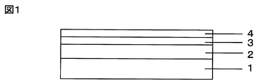
- the base resin layer 2 and the conductive layer 3 are laminated in this order on the base materials 15 and 16 constituting the upper and lower electrodes, and the conductive layers 3 of the upper and lower electrodes sandwich the space 20.
- the transparent protective layer 4 may be provided on the conductive layer 3 of the substrate 15 or 16.
- Dot spacers 18 are provided in the space 20 at regular intervals, thereby holding a gap between the upper and lower conductive layers.
- the upper surface of the base material 15 is a surface where the pen 22 and the tip of the finger come into contact, and a hard coat layer 17 is provided to prevent scratches.
- voltage is applied by the power source 21 and the surface of the hard coat layer 17 is pushed by the pen 22 or the tip of a finger to apply a load, whereby electricity flows from the contacted portion.
- the touch panel having the above configuration is used, for example, by attaching a lead wire and a drive unit and incorporating it on the front surface of the liquid crystal display.
- the resistive film type touch panel shown in FIG. 4 is configured through the space 20, the base resin layer is deformed by a load when input with a pen or a finger, thereby improving the writing quality and input sensitivity of the touch panel.
- This is a touch panel configuration that is extremely effective and has the highest effect of using the conductive laminate of the present invention.
- each substance is appropriately concentrated and diluted, and nuclear magnetic resonance spectroscopy ( 1 H-NMR, 13 C-NMR), two-dimensional nuclear magnetic resonance spectroscopy (2D-NMR), infrared spectrophotometry (IR), Raman spectroscopy, mass spectrometry (Mass), X-ray diffraction (XRD), neutron diffraction (ND), low-energy electron diffraction (LEED), high-energy reflection electron diffraction (RHEED), atomic absorption spectrometry ( AAS), ultraviolet photoelectron spectroscopy (UPS), X-ray photoelectron spectroscopy (XPS), X-ray fluorescence elemental analysis (XRF), inductively coupled plasma emission spectroscopy (ICP-AES), electron beam microanalyzer (EPMA), Structural identification was performed by appropriately selecting and combining methods from gel permeation chromatography (GPC) and other elemental analysis.
- GPC gel permeation chromatography
- Base material thickness T base resin layer thickness t
- the sample was cut in a direction perpendicular to the sample plane at a knife inclination angle of 3 ° using a rotary microtome manufactured by Nippon Microtome Laboratories.
- ABT-32 manufactured by Topcon Corporation, select any three magnifications from an observation magnification of 2500 to 10000 times, and adjust the contrast of the image as appropriate, and observe the obtained sample cross section at each magnification.
- From the obtained cross-sectional photograph arbitrary five locations respectively corresponding to the base material and the base resin layer were similarly measured at arbitrary three magnifications (calculated from the enlargement magnification), and the average values of the total 15 locations were thicknesses T and t, respectively. It was.
- Total light transmittance Total light transmittance in the thickness direction of the conductive laminate based on JIS K7361-1 (1997) using a turbidimeter (cloudiness meter) NDH2000 (manufactured by Nippon Denshoku Industries Co., Ltd.) The rate was measured by making light incident from the conductive layer side. The average value of the values measured for the five samples was calculated and used as the total light transmittance.
- the indicators of the text quality and input sensitivity are the ON load [g] and the contact resistance value [k ⁇ ].
- the ON load is, for example, the minimum load at which the touch panel can be operated for the first time when the touch panel shown in FIG. 4 is loaded with the pen 22, and the touch panel can operate.
- the ON load is weaker. This means that the touch panel can be operated with force, and is an indicator of writing quality.
- the contact resistance is a resistance value when electricity flows from the surface where the upper and lower electrodes in FIG. 4 are in contact with each other when a load is applied, and the upper and lower electrodes are in contact via the space 20. If not, the insulation state is established, the contact resistance value becomes infinite, and electricity does not flow. The lower the contact resistance value, the better the input sensitivity is.
- the ON load and contact resistance value were determined as follows. First, in the touch panel of FIG. 4, conductive glass with ITO (made by Touch Panel Laboratories Co., Ltd.) is used as the lower electrode 14, and the conductive laminates of the examples and comparative examples of the present invention are used as the upper electrode, respectively. A touch panel was prepared. Next, using a HEIDON TRIBOGEAR surface property measuring instrument TYPE: HEIDON-14DR (manufactured by Shinto Kagaku Co., Ltd.), a polyacetal pen with a radius of 0.8 mm on the sample stage side of the attached load unit.
- HEIDON TRIBOGEAR surface property measuring instrument TYPE: HEIDON-14DR manufactured by Shinto Kagaku Co., Ltd.
- the surface opposite to the transparent measurement surface (the surface on which the transparent protective layer is provided) is evenly distributed with water resistant sandpaper No. 320-400 so that the 60 ° C glossiness (JIS Z 8741 (1997)) is 10 or less. After roughening, a black paint was applied and colored so that the visible light transmittance was 5% or less.
- a spectrophotometer UV-3150 manufactured by Shimadzu Corporation, the absolute reflection spectrum in the wavelength region of 300 nm to 800 nm was measured at an interval of 1 nm at an incident angle of 5 degrees from the measurement surface, and at a wavelength of 380 nm to 780 nm. Average reflectance was determined.
- Resins, photopolymerization initiators, and films used in Examples and Comparative Examples are shown below.
- Resin A Art Resin LPVC-3 manufactured by Negami Kogyo Co., Ltd., polypropylene glycol skeleton bifunctional urethane acrylate, solid concentration 100 mass%).
- Resin B Chemitly (registered trademark) L-20 manufactured by Soken Chemical Co., Ltd., graft acrylic having a hydroxyl group (—OH) as a hydrophilic group in the side chain, solid content concentration: 26 mass% solution).
- Resin C Art Resin UN-7600 manufactured by Negami Kogyo Co., Ltd., polyester skeleton bifunctional urethane acrylate, solid concentration 100 mass%).
- Resin D Aronix registered trademark
- M240 manufactured by Toagosei Co., Ltd., polyethylene glycol skeleton bifunctional acrylate, solid concentration 100 mass%).
- Resin E Aronix registered trademark
- M270 manufactured by Toagosei Co., Ltd., polypropylene glycol skeleton bifunctional acrylate, solid concentration 100 mass%).
- Resin F TRSC-006 manufactured by Negami Kogyo Co., Ltd., polypropylene glycol skeleton bifunctional urethane, solid concentration 58.8% by mass solution.
- Resin G X-22-8114 manufactured by Shin-Etsu Chemical Co., Ltd., graft acrylic, which is a silicone having a side chain having a methyl group (—CH 3 ) and an n-butyl (—CH 2 CH 2 CH 2 CH 3 ) group, solid content 40% by weight solution).
- Conductive layer A “Carbon nanotube conductive layer” (Catalyst adjustment) 2.459 g of ammonium iron citrate (green) (manufactured by Wako Pure Chemical Industries, Ltd.) was dissolved in 500 mL of methanol (manufactured by Kanto Chemical Co., Inc.). To this solution, 100 g of light magnesia (Iwatani Chemical Industry Co., Ltd.) was added, stirred at room temperature for 60 minutes, dried under reduced pressure while stirring at 40 ° C. to 60 ° C. to remove methanol, and a metal salt was added to the light magnesia powder. Was obtained.
- the reactor 100 is a cylindrical quartz tube having an inner diameter of 32 mm and a length of 1200 mm.
- a quartz sintered plate 101 is provided at the center, an inert gas and source gas supply line 104 is provided at the lower part of the quartz tube, and an exhaust gas line 105 and a catalyst charging line 103 are provided at the upper part.
- a heater 106 is provided that surrounds the circumference of the reactor so that the reactor can be maintained at an arbitrary temperature.
- the heater 106 is provided with an inspection port 107 so that the flow state in the apparatus can be confirmed.
- the temperature was maintained, the argon flow rate of the raw material gas supply line 104 was increased to 2000 mL / min, and fluidization of the solid catalyst on the quartz sintered plate was started. After confirming fluidization from the heating furnace inspection port 107, supply of methane to the reactor at 95 mL / min was started. After supplying the mixed gas for 90 minutes, the flow was switched to a flow of only argon gas, and the synthesis was terminated.
- the heating was stopped and the mixture was allowed to stand at room temperature, and after reaching room temperature, the carbon nanotube composition containing the catalyst and carbon nanotubes was taken out from the reactor.
- Carbon nanotube dispersion coating solution In a 50 mL container, 10 mg of the above carbon nanotube composition (converted when dried), 10 mg of sodium carboxymethylcellulose (Sigma, 90 kDa, 50-200 cps) as a dispersant, add distilled water to 10 g, and output an ultrasonic homogenizer of 20 W. Then, the dispersion treatment was carried out under ice cooling for 20 minutes to prepare a carbon nanotube coating solution. The obtained liquid was centrifuged at 10,000 G for 15 minutes with a high-speed centrifuge to obtain 9 mL of the supernatant.
- sodium carboxymethylcellulose Sigma, 90 kDa, 50-200 cps
- the carbon nanotube dispersion coating liquid was applied with a micro gravure coater (gravure wire number 100R or 150R, gravure rotation ratio 80%) and dried at 100 ° C. for 1 minute to provide a carbon nanotube coating film.
- a micro gravure coater gravure wire number 100R or 150R, gravure rotation ratio 80%
- Silver nanowires were obtained by the method disclosed in Example 1 (synthesis of silver nanowires) of International Publication No. WO2007 / 022226.
- a silver nanowire-dispersed coating liquid was obtained by the method disclosed in Example 8 (nanowire dispersion) of International Publication No. WO2007 / 022226.
- This silver nanowire-dispersed coating solution was applied using a bar coater manufactured by Matsuo Sangyo Co., Ltd. and dried at 120 ° C. for 2 minutes to provide a silver nanowire coating film.
- the transparent protective layer in Examples and Comparative Examples is shown below.
- the transparent protective layer was laminated on the conductive layer by the methods of Examples and Comparative Examples.
- Transparent protective layer material A In a 100 mL plastic container, 20 g of ethanol was added, and 40 g of n-butyl silicate was added and stirred for 30 minutes. Thereafter, 10 g of 0.1N hydrochloric acid aqueous solution was added, and the mixture was stirred for 2 hours (hydrolysis reaction) and stored at 4 ° C. On the next day, this solution was diluted with an isopropyl alcohol / toluene / n-butanol mixed solution (mixing mass ratio 2/1/1) so that the solid concentration was 1.0, 1.2, and 1.5% by mass. . The refractive index of the transparent protective layer of silicon oxide obtained by applying this solution to a silicon wafer and drying was 1.44.
- Transparent protective layer material B A hollow silica particle-containing acrylic UV curable low refractive index material TU-2180 (solid content concentration 10 mass%) manufactured by JSR Corporation was diluted with methyl ethyl ketone so that the solid content concentration was 1.5 mass%.
- Example 1 KAYANOVA (registered trademark) FOP1740 (Nippon Kayaku Co., Ltd., solid content concentration 82% by mass) on one side with a “film” having a thickness of 188 ⁇ m as a base material and a solid content concentration of 40: 1 with toluene / methyl ethyl ketone mass% ratio.
- a hard coating agent diluted to mass% is applied with a micro gravure coater (gravure wire number 80R, gravure rotation ratio 100%), dried at 80 ° C. for 1 minute, irradiated with ultraviolet rays at 1.0 J / cm 2 and cured to a thickness of 5 ⁇ m.
- the hard coat layer was provided.
- a base resin layer coating solution 1.40 g of “resin A”, 13.85 g of “resin B”, and 2.00 g of ethyl acetate were mixed and stirred to prepare a base resin layer coating solution.
- This base resin layer coating solution is applied to the opposite surface of the base material provided with the hard coat layer using a bar coater count 30 manufactured by Matsuo Sangyo Co., Ltd., and dried by heating at 100 ° C. for 3 minutes.
- a base resin layer having a subsequent coating thickness of 13 ⁇ m was provided.
- conductive layer A was laminated on the base resin layer with a gravure wire number 150R to obtain a conductive laminate of the present invention.
- Example 2 The composition of the base resin layer coating solution is 1.40 g of “resin A”, 13.96 g of “resin B”, 0.041 g of “photopolymerization initiator”, and 2.08 g of ethyl acetate. Created in the same manner as in Example 1 except that ultraviolet rays were irradiated at 1.2 J / cm 2 , and “conductive layer A” was laminated with gravure wire number 150R on a base resin layer having a coating thickness after drying of 13 ⁇ m. The conductive laminate of the present invention was obtained.
- Example 3 KAYANOVA (registered trademark) FOP1740 (Nippon Kayaku Co., Ltd., solid content concentration 82% by mass) on one side with a “film” having a thickness of 188 ⁇ m as a base material and a solid content concentration of 40: 1 with toluene / methyl ethyl ketone mass% ratio.
- a hard coating agent diluted to mass% is applied with a micro gravure coater (gravure wire number 80R, gravure rotation ratio 100%), dried at 80 ° C. for 1 minute, irradiated with ultraviolet rays at 1.0 J / cm 2 and cured to a thickness of 5 ⁇ m.
- the hard coat layer was provided.
- conductive layer B was laminated on the base resin layer to obtain a conductive laminate of the present invention.
- Example 4 KAYANOVA (registered trademark) FOP1740 (Nippon Kayaku Co., Ltd., solid concentration 82 mass%) on one side with a “film” having a thickness of 125 ⁇ m as a one-to-one ratio of toluene to methyl ethyl ketone mass ratio 40
- a hard coating agent diluted to mass% is applied with a micro gravure coater (gravure wire number 80R, gravure rotation ratio 100%), dried at 80 ° C. for 1 minute, irradiated with ultraviolet rays at 1.0 J / cm 2 and cured to a thickness of 5 ⁇ m.
- the hard coat layer was provided.
- a base resin layer coating solution 3.64 g of “resin A”, 1.38 g of “resin B”, and 14.97 g of ethyl acetate were mixed and stirred to prepare a base resin layer coating solution.
- This base resin layer coating solution is applied to the opposite side of the base material provided with the hard coat layer using a bar coater count 24 manufactured by Matsuo Sangyo Co., Ltd., and dried by heating at 100 ° C. for 3 minutes. A base resin layer having a subsequent coating thickness of 7 ⁇ m was provided.
- “conductive layer B” was laminated on the base resin layer to obtain a conductive laminate of the present invention.
- Example 5 The base resin layer coating solution was prepared in the same manner as in Example 4 except that 3.84 g of “resin A”, 0.62 g of “resin B”, and 15.55 g of ethyl acetate, and the coating thickness after drying was A “conductive layer B” was laminated on a 7 ⁇ m ground resin layer to obtain a conductive laminate of the present invention.
- Example 6 KAYANOVA (registered trademark) FOP1740 (Nippon Kayaku Co., Ltd., solid concentration 82 mass%) on one side with a “film” having a thickness of 125 ⁇ m as a one-to-one ratio of toluene to methyl ethyl ketone mass ratio 40
- a hard coating agent diluted to mass% is applied with a micro gravure coater (gravure wire number 80R, gravure rotation ratio 100%), dried at 80 ° C. for 1 minute, irradiated with ultraviolet rays at 1.0 J / cm 2 and cured to a thickness of 5 ⁇ m.
- the hard coat layer was provided.
- a base resin layer coating solution 1.40 g of “resin A”, 13.96 g of “resin B”, 0.041 g of “photopolymerization initiator”, and 9.95 g of ethyl acetate were mixed and stirred to prepare a base resin layer coating solution.
- This base resin layer coating solution is applied to the opposite surface of the base material provided with the hard coat layer using a bar coater count 24 manufactured by Matsuo Sangyo Co., Ltd. 1.2 J / cm 2 was irradiated and cured, and a base resin layer having a coating thickness of 7 ⁇ m was provided.
- conductive layer A was laminated on the base resin layer with a gravure wire number 150R to obtain a conductive laminate of the present invention.
- Example 7 The composition of the base resin layer coating solution is 1.80 g of “resin A”, 8.48 g of “resin B”, 0.043 g of “photopolymerization initiator”, and 9.92 g of ethyl acetate. Except that the ultraviolet ray was irradiated at 1.2 J / cm 2 , it was prepared in the same manner as in Example 6, and the “conductive layer A” was laminated on the base resin layer having a coating thickness of 7 ⁇ m with a gravure wire number 150R. A conductive laminate was obtained.
- Example 8 The composition of the base resin layer coating solution is 1.00 g of “resin A”, 16.40 g of “resin B”, 0.030 g of “photopolymerization initiator”, 9.04 g of ethyl acetate, and after applying and drying the coating solution, Except that the ultraviolet ray was irradiated at 1.2 J / cm 2 , it was prepared in the same manner as in Example 6, and the “conductive layer A” was laminated on the base resin layer having a coating thickness of 7 ⁇ m with a gravure wire number 150R. A conductive laminate was obtained.
- Example 9 The composition of the base resin layer coating solution was 0.80 g of “resin A”, 18.90 g of “resin B”, 0.024 g of “photopolymerization initiator”, and 8.97 g of “ethyl acetate”, and the coating solution was applied and dried. Later, it was prepared in the same manner as in Example 6 except that ultraviolet rays were further irradiated at 1.2 J / cm 2 , and “conductive layer A” was laminated with gravure wire number 150R on the base resin layer having a coating thickness of 7 ⁇ m. The conductive laminate of the present invention was obtained.
- Example 10 KAYANOVA (registered trademark) FOP1740 (Nippon Kayaku Co., Ltd., solid concentration 82 mass%) on one side with a “film” having a thickness of 125 ⁇ m as a one-to-one ratio of toluene to methyl ethyl ketone mass ratio 40
- a hard coating agent diluted to mass% is applied with a micro gravure coater (gravure wire number 80R, gravure rotation ratio 100%), dried at 80 ° C. for 1 minute, irradiated with ultraviolet rays at 1.0 J / cm 2 and cured to a thickness of 5 ⁇ m.
- the hard coat layer was provided.
- a base resin layer coating solution 0.50 g of “resin A”, 19.44 g of “resin B”, 0.015 g of “photopolymerization initiator”, and 0.67 g of ethyl acetate were mixed and stirred to prepare a base resin layer coating solution.
- This base resin layer coating solution was applied to the opposite surface of the base material provided with the hard coat layer using a bar coater count 26 manufactured by Matsuo Sangyo Co., Ltd. Was irradiated and cured to 1.2 J / cm 2 to provide a base resin layer having a coating thickness of 10.5 ⁇ m.
- conductive layer A was laminated on the base resin layer with a gravure wire number 150R to obtain a conductive laminate of the present invention.
- Example 11 KAYANOVA (registered trademark) FOP1740 (Nippon Kayaku Co., Ltd., solid concentration 82 mass%) on one side with a “film” having a thickness of 125 ⁇ m as a one-to-one ratio of toluene to methyl ethyl ketone mass ratio 40
- a hard coating agent diluted to mass% is applied with a micro gravure coater (gravure wire number 80R, gravure rotation ratio 100%), dried at 80 ° C. for 1 minute, irradiated with ultraviolet rays at 1.0 J / cm 2 and cured to a thickness of 5 ⁇ m.
- the hard coat layer was provided.
- a base resin layer coating solution 1.00 g of “resin A”, 9.89 g of “resin B”, 0.030 g of “photopolymerization initiator” and 7.09 g of ethyl acetate were mixed and stirred to prepare a base resin layer coating solution.
- This base resin layer coating solution is applied to the opposite surface of the base material provided with the hard coat layer using a bar coater count 16 manufactured by Matsuo Sangyo Co., Ltd. 1.2 J / cm 2 irradiation and curing were performed, and a base resin layer having a coating thickness of 4.8 ⁇ m was provided.
- conductive layer A was laminated on the base resin layer with a gravure wire number 150R to obtain a conductive laminate of the present invention.
- Example 12 Except having laminated
- Example 13 On the “conductive layer A” of Example 6, a coating solution of “transparent protective layer material A” having a solid content concentration of 1.0 mass% was applied by microgravure coating (gravure wire number 80R, gravure rotation ratio 100%). The film was dried at 125 ° C. for 1 minute to provide a transparent protective layer having a thickness of 60 nm to obtain a conductive laminate of the present invention.
- Example 14 On the “conductive layer A” of Example 6, a coating solution of “transparent protective layer material A” having a solid content concentration of 1.2 mass% was applied by microgravure coating (gravure wire number 80R, gravure rotation ratio 100%). The film was dried at 125 ° C. for 1 minute, and a transparent protective layer having a thickness of 75 nm was provided to obtain a conductive laminate of the present invention.
- Example 15 On the “conductive layer A” of Example 6, a coating solution of “transparent protective layer material A” having a solid content concentration of 1.5 mass% was applied by microgravure coating (gravure wire number 80R, gravure rotation ratio 100%). The film was dried at 125 ° C. for 1 minute to provide a transparent protective layer having a thickness of 100 nm to obtain a conductive laminate of the present invention.
- Example 16 A coating liquid of “transparent protective layer material B” having a solid content concentration of 1.5% by mass was applied by microgravure coating (gravure wire number 120R, gravure rotation ratio 100%) on “conductive layer A” of Example 6. After drying at 80 ° C. for 30 seconds, the film was cured by irradiation with ultraviolet rays of 1.2 J / cm 2 to provide a transparent protective layer having a thickness of 65 nm to obtain a conductive laminate of the present invention.
- microgravure coating gravure wire number 120R, gravure rotation ratio 100%
- Example 17 On the “conductive layer A” in Example 6, a coating solution of “transparent protective layer material B” having a solid content concentration of 1.5 mass% was applied by microgravure coating (gravure wire number 80R, gravure rotation ratio 100%). After drying at 80 ° C. for 30 seconds, the film was cured by irradiation with ultraviolet rays of 1.2 J / cm 2 to provide a transparent protective layer having a thickness of 100 nm to obtain a conductive laminate of the present invention.
- microgravure coating gravure wire number 80R, gravure rotation ratio 100%
- Comparative Example 1 KAYANOVA (registered trademark) FOP1740 (Nippon Kayaku Co., Ltd., solid content concentration 82% by mass) on one side with a “film” having a thickness of 188 ⁇ m as a base material and a solid content concentration of 40: 1 with toluene / methyl ethyl ketone mass% ratio.
- a hard coating agent diluted to mass% is applied with a micro gravure coater (gravure wire number 80R, gravure rotation ratio 100%), dried at 80 ° C. for 1 minute, irradiated with ultraviolet rays at 1.0 J / cm 2 and cured to a thickness of 5 ⁇ m.
- the hard coat layer was provided. Subsequently, it was set as the laminated body which does not provide a base resin layer and a conductive layer on the opposite surface which provided the hard-coat layer of the base material.
- Comparative Example 2 KAYANOVA (registered trademark) FOP1740 (Nippon Kayaku Co., Ltd., solid content concentration 82% by mass) on one side with a “film” having a thickness of 188 ⁇ m as a base material and a solid content concentration of 40: 1 with toluene / methyl ethyl ketone mass% ratio.
- a hard coating agent diluted to mass% is applied with a micro gravure coater (gravure wire number 80R, gravure rotation ratio 100%), dried at 80 ° C. for 1 minute, irradiated with ultraviolet rays at 1.0 J / cm 2 and cured to a thickness of 5 ⁇ m.
- the hard coat layer was provided.
- Comparative Example 3 KAYANOVA (registered trademark) FOP1740 (Nippon Kayaku Co., Ltd., solid content concentration 82% by mass) on one side with a “film” having a thickness of 188 ⁇ m as a base material and a solid content concentration of 40: 1 with toluene / methyl ethyl ketone mass% ratio.
- a hard coating agent diluted to mass% is applied with a micro gravure coater (gravure wire number 80R, gravure rotation ratio 100%), dried at 80 ° C. for 1 minute, irradiated with ultraviolet rays at 1.0 J / cm 2 and cured to a thickness of 5 ⁇ m.
- the hard coat layer was provided.
- the “conductive layer C” was directly laminated on the opposite surface of the base material on which the hard coat layer was provided, without providing the base resin layer, to obtain a conductive laminate.
- Comparative Example 4 A conductive laminate was prepared in the same manner as in Comparative Example 3 except that the conductive layer was “conductive layer A” (laminated with gravure wire number 150R).
- Comparative Example 5 A conductive laminate was prepared in the same manner as Comparative Example 3 except that the conductive layer was “conductive layer B”.
- Comparative Example 6 Except that the resin used for the base resin layer coating solution was “resin C”, it was prepared in the same manner as in Example 1, and “conductive layer A” was formed on the base resin layer having a coating thickness after drying of 13 ⁇ m. No. 150R was laminated to obtain a conductive laminate.
- Comparative Example 7 A conductive laminate was prepared in the same manner as Comparative Example 6 except that the “conductive layer A” to be laminated was laminated with the gravure wire number 100R.
- Comparative Example 8 Except that the resin used for the base resin layer coating solution was “resin D”, it was prepared in the same manner as in Example 2, and “conductive layer A” was formed on the base resin layer having a coating thickness after drying of 13 ⁇ m. No. 150R was laminated to obtain a conductive laminate.
- Comparative Example 9 Except that the resin used for the base resin layer coating solution was “resin E”, it was prepared in the same manner as in Example 28, and “conductive layer A” was formed on the base resin layer having a coating thickness after drying of 13 ⁇ m. No. 150R was laminated to obtain a conductive laminate.
- Comparative Example 10 KAYANOVA (registered trademark) FOP1740 (Nippon Kayaku Co., Ltd., solid content concentration 82% by mass) on one side with a “film” having a thickness of 188 ⁇ m as a base material and a solid content concentration of 40: 1 with toluene / methyl ethyl ketone mass% ratio.
- a hard coating agent diluted to mass% is applied with a micro gravure coater (gravure wire number 80R, gravure rotation ratio 100%), dried at 80 ° C. for 1 minute, irradiated with ultraviolet rays at 1.0 J / cm 2 and cured to a thickness of 5 ⁇ m.
- the hard coat layer was provided.
- a base resin layer coating solution 1.00 g of “resin F”, 5.82 g of “resin B”, and 0.43 g of ethyl acetate were mixed and stirred to prepare a base resin layer coating solution.
- This base resin layer coating solution was applied to the opposite surface of the base material provided with the hard coat layer using a bar coater count 30 manufactured by Matsuo Sangyo Co., Ltd., and heated and dried at 100 ° C. for 3 minutes. A base resin layer having a coating thickness of 13 ⁇ m after drying was provided.
- conductive layer A was laminated on the base resin layer with a gravure wire number 150R to obtain a conductive laminate.
- Comparative Example 11 KAYANOVA (registered trademark) FOP1740 (Nippon Kayaku Co., Ltd., solid content concentration 82% by mass) on one side with a “film” having a thickness of 188 ⁇ m as a base material and a solid content concentration of 40: 1 with toluene / methyl ethyl ketone mass% ratio.
- a hard coating agent diluted to mass% is applied with a micro gravure coater (gravure wire number 80R, gravure rotation ratio 100%), dried at 80 ° C. for 1 minute, irradiated with ultraviolet rays at 1.0 J / cm 2 and cured to a thickness of 5 ⁇ m.
- the hard coat layer was provided.
- a base resin layer coating solution 1.00 g of “resin F”, 3.87 g of “resin G” and 2.46 g of ethyl acetate were mixed and stirred to prepare a base resin layer coating solution.
- This base resin layer coating solution is applied to the opposite surface of the base material provided with the hard coat layer using a bar coater count 30 manufactured by Matsuo Sangyo Co., Ltd., and dried by heating at 100 ° C. for 3 minutes. A base resin layer having a subsequent coating thickness of 13 ⁇ m was provided.
- Examples 1 to 17 the writing quality and input sensitivity of the touch panel could be improved.
- a base resin layer in which a urethane acrylate having a specific structure of a glycol skeleton and a bifunctional acrylate moiety and a graft resin having a hydrophilic group in the side chain is used (Examples 1 to 4).
- 3, 6, 13-17) Not only was it possible to apply a water-dispersed coating liquid of the conductive component of the linear structure, but also the writing quality and input sensitivity were greatly improved.
- the acrylate moiety of the urethane acrylate resin was bonded to another acrylate moiety (Examples 2, 6, 13 to 17), good durability could be obtained.
- the present invention is a conductive laminate having good touch panel writing, high input sensitivity, and good durability. Furthermore, it is an electroconductive laminated body used also for electrode members used, such as a liquid crystal display, organic electroluminescence, electronic paper related display, and a solar cell module.
Priority Applications (4)
| Application Number | Priority Date | Filing Date | Title |
|---|---|---|---|
| US13/509,173 US20120231248A1 (en) | 2009-11-11 | 2010-11-01 | Conductive laminate and method of producing the same |
| CN201080045653.1A CN102574388B (zh) | 2009-11-11 | 2010-11-01 | 导电层合体及其制造方法 |
| JP2011502185A JP5423784B2 (ja) | 2009-11-11 | 2010-11-01 | 導電積層体およびその製造方法 |
| EP20100829858 EP2500170A4 (en) | 2009-11-11 | 2010-11-01 | ELECTRICALLY CONDUCTIVE LAMINATE AND METHOD OF MANUFACTURING THEREOF |
Applications Claiming Priority (2)
| Application Number | Priority Date | Filing Date | Title |
|---|---|---|---|
| JP2009257833 | 2009-11-11 | ||
| JP2009-257833 | 2009-11-11 |
Publications (1)
| Publication Number | Publication Date |
|---|---|
| WO2011058898A1 true WO2011058898A1 (ja) | 2011-05-19 |
Family
ID=43991557
Family Applications (1)
| Application Number | Title | Priority Date | Filing Date |
|---|---|---|---|
| PCT/JP2010/069405 WO2011058898A1 (ja) | 2009-11-11 | 2010-11-01 | 導電積層体およびその製造方法 |
Country Status (7)
| Country | Link |
|---|---|
| US (1) | US20120231248A1 (zh) |
| EP (1) | EP2500170A4 (zh) |
| JP (1) | JP5423784B2 (zh) |
| KR (1) | KR20120101381A (zh) |
| CN (1) | CN102574388B (zh) |
| TW (1) | TW201126547A (zh) |
| WO (1) | WO2011058898A1 (zh) |
Cited By (7)
| Publication number | Priority date | Publication date | Assignee | Title |
|---|---|---|---|---|
| WO2012002332A1 (ja) * | 2010-07-02 | 2012-01-05 | 富士フイルム株式会社 | 導電層転写材料、及びタッチパネル |
| WO2013191228A1 (en) * | 2012-06-18 | 2013-12-27 | Fujifilm Corporation | Under layer film-forming composition for imprints and method of forming pattern |
| US20140050909A1 (en) * | 2012-01-27 | 2014-02-20 | Jin Hee Choi | Laminate for window sheet, window sheet comprising the same, and display apparatus comprising the same |
| JP2014188828A (ja) * | 2013-03-27 | 2014-10-06 | Toppan Printing Co Ltd | 透明導電性フィルム |
| JP2015133090A (ja) * | 2014-01-14 | 2015-07-23 | サムソン エレクトロ−メカニックス カンパニーリミテッド. | タッチパネル |
| JP2016507801A (ja) * | 2012-12-07 | 2016-03-10 | スリーエム イノベイティブ プロパティズ カンパニー | 導電性物品 |
| JP2016076013A (ja) * | 2014-10-03 | 2016-05-12 | コニカミノルタ株式会社 | 透明導電フィルム、その製造方法及びタッチパネル |
Families Citing this family (23)
| Publication number | Priority date | Publication date | Assignee | Title |
|---|---|---|---|---|
| CN103123547A (zh) * | 2011-11-16 | 2013-05-29 | 宸鸿科技(厦门)有限公司 | 光学面板的堆叠结构及其制造方法 |
| WO2013089085A1 (ja) * | 2011-12-16 | 2013-06-20 | 富士フイルム株式会社 | 導電シート及びタッチパネル |
| TWI460644B (zh) * | 2012-01-06 | 2014-11-11 | Egalax Empia Technology Inc | 薄型電容式觸摸屏 |
| CN103325441A (zh) * | 2012-03-21 | 2013-09-25 | 宸鸿科技(厦门)有限公司 | 触控面板之导电薄膜及其制造方法 |
| CN104520793B (zh) * | 2012-09-27 | 2017-09-29 | 东丽薄膜先端加工股份有限公司 | 透明导电层合体 |
| CN103838440B (zh) * | 2012-11-23 | 2016-08-10 | 北京富纳特创新科技有限公司 | 触摸屏 |
| CN103838455B (zh) * | 2012-11-23 | 2016-12-21 | 北京富纳特创新科技有限公司 | 电阻式触摸屏 |
| KR102148154B1 (ko) * | 2013-01-22 | 2020-08-26 | 주식회사 동진쎄미켐 | 투명 전도성 막 코팅 조성물, 투명 전도성 막 및 투명 전도성 막의 제조 방법 |
| KR20140110539A (ko) | 2013-03-08 | 2014-09-17 | 삼성디스플레이 주식회사 | 표시 장치 |
| WO2014196354A1 (ja) * | 2013-06-07 | 2014-12-11 | 星光Pmc株式会社 | 金属ナノワイヤ含有組成物 |
| KR102035715B1 (ko) | 2013-06-27 | 2019-10-24 | 삼성디스플레이 주식회사 | 액정 표시 장치 |
| US10042446B2 (en) | 2013-08-13 | 2018-08-07 | Samsung Electronics Company, Ltd. | Interaction modes for object-device interactions |
| US9569055B2 (en) | 2013-08-13 | 2017-02-14 | Samsung Electronics Company, Ltd. | Interaction sensing |
| KR20150112924A (ko) * | 2013-10-16 | 2015-10-07 | 히타치가세이가부시끼가이샤 | 도전성 섬유를 포함하는 적층체, 감광성 도전 필름, 도전 패턴의 제조 방법, 도전 패턴 기판, 및 터치 패널 |
| KR101477430B1 (ko) * | 2013-12-30 | 2014-12-29 | 삼성전기주식회사 | 적층 세라믹 전자부품, 그 제조방법 및 적층 세라믹 전자부품의 실장 기판 |
| CN104505150A (zh) * | 2014-12-09 | 2015-04-08 | 广州北峻工业材料有限公司 | 一种透明导电膜及其制备方法 |
| CN104575701B (zh) * | 2014-12-17 | 2017-01-11 | 张家港康得新光电材料有限公司 | 高分子透明导电膜及其制备方法 |
| KR20170130175A (ko) * | 2016-05-18 | 2017-11-28 | 삼성전자주식회사 | 셀룰로스 분리막을 제조하는 방법, 그에 의하여 제조된 셀룰로스 분리막 및 그를 포함하는 이차이온전지 |
| WO2018172269A1 (en) | 2017-03-21 | 2018-09-27 | Basf Se | Electrically conductive film comprising nanoobjects |
| EP3401928B1 (en) * | 2017-05-09 | 2021-08-18 | Henkel AG & Co. KGaA | Electrically conductive adhesive for attaching solar cells |
| JP7378952B2 (ja) * | 2018-04-25 | 2023-11-14 | ナガセケムテックス株式会社 | 透明導電膜を有する光学積層体、及びコーティング組成物 |
| CN110942843A (zh) * | 2019-10-23 | 2020-03-31 | 清远高新华园科技协同创新研究院有限公司 | 电动汽车用高分子导电膜、生产设备及制备方法 |
| KR20210146491A (ko) * | 2020-05-26 | 2021-12-06 | 삼성디스플레이 주식회사 | 이송 복합체 및 이를 포함하는 이송 모듈 |
Citations (9)
| Publication number | Priority date | Publication date | Assignee | Title |
|---|---|---|---|---|
| JP2000079662A (ja) * | 1998-06-22 | 2000-03-21 | Toyobo Co Ltd | 高制電性積層体およびそれを用いた成形品 |
| JP2002098803A (ja) * | 2000-09-22 | 2002-04-05 | Fuji Photo Film Co Ltd | 透明導電・反射防止フイルム及びそれを用いた表示装置 |
| JP2004213990A (ja) * | 2002-12-27 | 2004-07-29 | Toyobo Co Ltd | 透明導電性フィルムおよびタッチパネル |
| JP2007042284A (ja) | 2003-10-27 | 2007-02-15 | Teijin Ltd | 透明導電性積層体及び透明タッチパネル |
| WO2007022226A2 (en) | 2005-08-12 | 2007-02-22 | Cambrios Technologies Corporation | Nanowires-based transparent conductors |
| JP2008004304A (ja) * | 2006-06-20 | 2008-01-10 | Fujifilm Corp | 導電性パターン形成方法、及びワイヤグリッド型偏光子 |
| JP2008243532A (ja) | 2007-03-27 | 2008-10-09 | Konica Minolta Holdings Inc | 透明導電性フィルム |
| WO2009038183A1 (ja) * | 2007-09-20 | 2009-03-26 | Toyo Boseki Kabushiki Kaisha | 粘着シート、タッチパネル用上部電極および画像表示装置 |
| JP2009302013A (ja) | 2008-06-17 | 2009-12-24 | Nof Corp | 透明導電性フィルム及びそれを備えるタッチパネル |
Family Cites Families (4)
| Publication number | Priority date | Publication date | Assignee | Title |
|---|---|---|---|---|
| MY136978A (en) * | 1998-06-22 | 2008-12-31 | Toyo Boseki | Highly antistatic laminate |
| WO2003032332A1 (fr) * | 2001-10-05 | 2003-04-17 | Bridgestone Corporation | Film transparent electroconducteur, son procede de fabrication, et ecran tactile y relatif |
| US7196136B2 (en) * | 2004-04-29 | 2007-03-27 | Hewlett-Packard Development Company, L.P. | UV curable coating composition |
| JP5266889B2 (ja) * | 2008-06-04 | 2013-08-21 | ソニー株式会社 | 光透過性導電体の製造方法 |
-
2010
- 2010-11-01 JP JP2011502185A patent/JP5423784B2/ja not_active Expired - Fee Related
- 2010-11-01 EP EP20100829858 patent/EP2500170A4/en not_active Withdrawn
- 2010-11-01 CN CN201080045653.1A patent/CN102574388B/zh not_active Expired - Fee Related
- 2010-11-01 KR KR20127012055A patent/KR20120101381A/ko not_active Application Discontinuation
- 2010-11-01 US US13/509,173 patent/US20120231248A1/en not_active Abandoned
- 2010-11-01 WO PCT/JP2010/069405 patent/WO2011058898A1/ja active Application Filing
- 2010-11-10 TW TW99138597A patent/TW201126547A/zh unknown
Patent Citations (9)
| Publication number | Priority date | Publication date | Assignee | Title |
|---|---|---|---|---|
| JP2000079662A (ja) * | 1998-06-22 | 2000-03-21 | Toyobo Co Ltd | 高制電性積層体およびそれを用いた成形品 |
| JP2002098803A (ja) * | 2000-09-22 | 2002-04-05 | Fuji Photo Film Co Ltd | 透明導電・反射防止フイルム及びそれを用いた表示装置 |
| JP2004213990A (ja) * | 2002-12-27 | 2004-07-29 | Toyobo Co Ltd | 透明導電性フィルムおよびタッチパネル |
| JP2007042284A (ja) | 2003-10-27 | 2007-02-15 | Teijin Ltd | 透明導電性積層体及び透明タッチパネル |
| WO2007022226A2 (en) | 2005-08-12 | 2007-02-22 | Cambrios Technologies Corporation | Nanowires-based transparent conductors |
| JP2008004304A (ja) * | 2006-06-20 | 2008-01-10 | Fujifilm Corp | 導電性パターン形成方法、及びワイヤグリッド型偏光子 |
| JP2008243532A (ja) | 2007-03-27 | 2008-10-09 | Konica Minolta Holdings Inc | 透明導電性フィルム |
| WO2009038183A1 (ja) * | 2007-09-20 | 2009-03-26 | Toyo Boseki Kabushiki Kaisha | 粘着シート、タッチパネル用上部電極および画像表示装置 |
| JP2009302013A (ja) | 2008-06-17 | 2009-12-24 | Nof Corp | 透明導電性フィルム及びそれを備えるタッチパネル |
Non-Patent Citations (1)
| Title |
|---|
| See also references of EP2500170A4 * |
Cited By (9)
| Publication number | Priority date | Publication date | Assignee | Title |
|---|---|---|---|---|
| WO2012002332A1 (ja) * | 2010-07-02 | 2012-01-05 | 富士フイルム株式会社 | 導電層転写材料、及びタッチパネル |
| US20140050909A1 (en) * | 2012-01-27 | 2014-02-20 | Jin Hee Choi | Laminate for window sheet, window sheet comprising the same, and display apparatus comprising the same |
| WO2013191228A1 (en) * | 2012-06-18 | 2013-12-27 | Fujifilm Corporation | Under layer film-forming composition for imprints and method of forming pattern |
| JP2016507801A (ja) * | 2012-12-07 | 2016-03-10 | スリーエム イノベイティブ プロパティズ カンパニー | 導電性物品 |
| US10076026B2 (en) | 2012-12-07 | 2018-09-11 | 3M Innovative Properties Company | Electrically conductive articles |
| US11449181B2 (en) | 2012-12-07 | 2022-09-20 | 3M Innovative Properties Company | Electrically conductive articles |
| JP2014188828A (ja) * | 2013-03-27 | 2014-10-06 | Toppan Printing Co Ltd | 透明導電性フィルム |
| JP2015133090A (ja) * | 2014-01-14 | 2015-07-23 | サムソン エレクトロ−メカニックス カンパニーリミテッド. | タッチパネル |
| JP2016076013A (ja) * | 2014-10-03 | 2016-05-12 | コニカミノルタ株式会社 | 透明導電フィルム、その製造方法及びタッチパネル |
Also Published As
| Publication number | Publication date |
|---|---|
| EP2500170A4 (en) | 2014-04-02 |
| US20120231248A1 (en) | 2012-09-13 |
| JP5423784B2 (ja) | 2014-02-19 |
| CN102574388A (zh) | 2012-07-11 |
| EP2500170A1 (en) | 2012-09-19 |
| KR20120101381A (ko) | 2012-09-13 |
| TW201126547A (en) | 2011-08-01 |
| JPWO2011058898A1 (ja) | 2013-03-28 |
| CN102574388B (zh) | 2014-05-14 |
Similar Documents
| Publication | Publication Date | Title |
|---|---|---|
| JP5423784B2 (ja) | 導電積層体およびその製造方法 | |
| JP5445042B2 (ja) | 導電積層体およびそれを用いてなるタッチパネル | |
| KR101811068B1 (ko) | 도전 적층체 및 그것을 이용하여 이루어지는 터치 패널 | |
| JP5793142B2 (ja) | 導電積層体およびタッチパネル | |
| KR101918335B1 (ko) | 나노구조화된 물품 및 이의 제조 방법 | |
| JP5521348B2 (ja) | 透明導電積層体 | |
| WO2014010270A1 (ja) | 導電積層体、パターン化導電積層体、その製造方法、および、それらを用いてなるタッチパネル | |
| JP2012066580A (ja) | 透明導電積層体 | |
| JP5428924B2 (ja) | 導電積層体およびそれを用いてなるタッチパネル | |
| CN107562251B (zh) | 用于触摸传感器的可转移纳米复合材料 | |
| KR20220013564A (ko) | 투명 도전성 폴리에스테르 필름과 그 용도 | |
| JP2012069515A (ja) | 透明導電積層体およびその製造方法 | |
| JP5273325B1 (ja) | 導電積層体およびそれを用いてなる表示体 | |
| JP2012183737A (ja) | 導電積層体およびそれを用いてなるタッチパネル | |
| JP2014017110A (ja) | 導電積層体およびそれを用いた偏光板、ディスプレイ、タッチパネル装置 | |
| JP2023159680A (ja) | 透明導電性フィルム | |
| JP2014102962A (ja) | 導電積層体、パターン化導電積層体、その製造方法、および、それらを用いてなるタッチパネル | |
| JP2017065053A (ja) | 導電積層体 | |
| JP2011103231A (ja) | 透明導電複合材の製造方法およびそれを用いたタッチパネル | |
| JP2016081210A (ja) | 導電性積層体およびそれを用いたタッチパネル | |
| TW202346091A (zh) | 光學積層體、物品 |
Legal Events
| Date | Code | Title | Description |
|---|---|---|---|
| WWE | Wipo information: entry into national phase |
Ref document number: 201080045653.1 Country of ref document: CN |
|
| ENP | Entry into the national phase |
Ref document number: 2011502185 Country of ref document: JP Kind code of ref document: A |
|
| 121 | Ep: the epo has been informed by wipo that ep was designated in this application |
Ref document number: 10829858 Country of ref document: EP Kind code of ref document: A1 |
|
| REEP | Request for entry into the european phase |
Ref document number: 2010829858 Country of ref document: EP |
|
| WWE | Wipo information: entry into national phase |
Ref document number: 2010829858 Country of ref document: EP |
|
| ENP | Entry into the national phase |
Ref document number: 20127012055 Country of ref document: KR Kind code of ref document: A |
|
| WWE | Wipo information: entry into national phase |
Ref document number: 13509173 Country of ref document: US |
|
| NENP | Non-entry into the national phase |
Ref country code: DE |