WO2011052014A1 - ヘッドレストステーおよびアクティブヘッドレスト - Google Patents
ヘッドレストステーおよびアクティブヘッドレスト Download PDFInfo
- Publication number
- WO2011052014A1 WO2011052014A1 PCT/JP2009/005757 JP2009005757W WO2011052014A1 WO 2011052014 A1 WO2011052014 A1 WO 2011052014A1 JP 2009005757 W JP2009005757 W JP 2009005757W WO 2011052014 A1 WO2011052014 A1 WO 2011052014A1
- Authority
- WO
- WIPO (PCT)
- Prior art keywords
- stay
- headrest
- head
- predetermined portion
- seat back
- Prior art date
- Legal status (The legal status is an assumption and is not a legal conclusion. Google has not performed a legal analysis and makes no representation as to the accuracy of the status listed.)
- Ceased
Links
Images




Classifications
-
- B—PERFORMING OPERATIONS; TRANSPORTING
- B60—VEHICLES IN GENERAL
- B60N—SEATS SPECIALLY ADAPTED FOR VEHICLES; VEHICLE PASSENGER ACCOMMODATION NOT OTHERWISE PROVIDED FOR
- B60N2/00—Seats specially adapted for vehicles; Arrangement or mounting of seats in vehicles
- B60N2/80—Head-rests
- B60N2/806—Head-rests movable or adjustable
- B60N2/809—Head-rests movable or adjustable vertically slidable
- B60N2/812—Head-rests movable or adjustable vertically slidable characterised by their locking devices
- B60N2/818—Head-rests movable or adjustable vertically slidable characterised by their locking devices with stepwise positioning
-
- B—PERFORMING OPERATIONS; TRANSPORTING
- B60—VEHICLES IN GENERAL
- B60N—SEATS SPECIALLY ADAPTED FOR VEHICLES; VEHICLE PASSENGER ACCOMMODATION NOT OTHERWISE PROVIDED FOR
- B60N2/00—Seats specially adapted for vehicles; Arrangement or mounting of seats in vehicles
- B60N2/80—Head-rests
- B60N2/888—Head-rests with arrangements for protecting against abnormal g-forces, e.g. by displacement of the head-rest
Definitions
- the present invention relates to a headrest stay and an active headrest, and more particularly to a headrest stay and an active headrest for a vehicle.
- Patent Document 1 discloses a technique in which a bent portion of a stay that is bent substantially in an inverted U shape is embedded in a pillow-like pad of a headrest.
- the stay when the stay is bent in an inverted U shape, when the stay has a pair of members extending in the vertical direction of the seat back and a member connecting the pair of members in the vehicle width direction, There is a possibility that the directional member may suppress movement of the head of the occupant. For example, when the passenger's head is supported by the headrest after a rear impact, the movement of the head in the vertical direction of the seat back may be suppressed due to the presence of the member in the vehicle width direction. A headrest stay that can more smoothly move the head in the seat back vertical direction is desired.
- An object of the present invention is to provide a headrest stay and an active headrest that can suppress the movement of the head in the vertical direction of the seat back.
- the headrest stay of the present invention is a pair of first stay components that extend in the vertical direction of the seat back while being supported by a seat back of a seat provided in the vehicle, and are arranged at different positions in the vehicle width direction.
- a second stay constituent part that connects a predetermined part that extends linearly in the vertical direction of the seat back in the vehicle width direction in each of the first stay constituent parts, and the predetermined part includes the seat
- the gap in the vehicle width direction between the one predetermined portion and the other predetermined portion is smaller than the width in the vehicle width direction of the seated person's head
- the second stay constituent part does not have a portion positioned in front of the frontmost part of the first stay constituent part, and one of the predetermined parts in the vehicle width direction among the second stay constituent parts.
- the other predetermined portion Portion the predetermined portion not positioned in front of the, and, at least partially, characterized in that positioned behind the predetermined portion.
- all of the portions located between the one predetermined portion and the other predetermined portion in the vehicle width direction may be located rearward of the predetermined portion. preferable.
- the headrest stay preferably includes a plate-like member that connects one of the predetermined portions and the other predetermined portion in the vehicle width direction.
- the active headrest of the present invention includes the headrest stay, a cover that covers the headrest stay, and a moving mechanism that moves the headrest stay in a direction to approach the seated person.
- the moving mechanism is operated by a mechanical input and moves the headrest stay at least forward, and the moving mechanism moves the upper part of the headrest stay in the up-down direction forward. It is preferable that the amount of movement is larger than the amount of movement for moving the lower part forward.
- the headrest stay according to the present invention includes a pair of first stay components extending in the vertical direction of the seat back and a predetermined portion extending linearly in the vertical direction of the seat back in each first stay component.
- a second stay constituent portion connected in the direction, the predetermined portion faces the head of the seat occupant, and one predetermined portion and the other predetermined portion in the vehicle width direction of the second stay constituent portions
- the part located between the parts is not located in front of the predetermined part, and at least a part thereof is located behind the predetermined part.
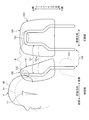
- FIG. 1 is a diagram illustrating a headrest stay according to the embodiment.
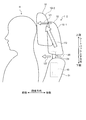
- FIG. 2 is a diagram illustrating how the head of the seated person moves.
- FIG. 3 is a diagram showing a backward tilt angle of the head H of the seated person at the time of a rear collision.
- FIG. 4 is a diagram illustrating an example of the operation of the headrest according to the embodiment.
- FIG. 5 is a diagram illustrating a schematic configuration of the headrest according to the embodiment.
- FIG. 6 is a view showing the stay extended upward from the seat back.
- FIG. 7 is a diagram illustrating an example of a headrest having a conventional stay.
- FIG. 1 is a front view and a side view of an embodiment of a headrest stay according to the present invention.
- the headrest 1-1 according to the present embodiment includes a main body 10 and a stay (headrest stay) 20.
- the main body 10 has a hollow coating (cover) 11.
- the stay 20 is composed of a pipe-shaped or solid rod-shaped member.
- the stay 20 is formed in a substantially U shape, and is disposed so that both end portions of the U shape are positioned on the lower side.
- the stay 20 extends in the up-down direction of the seat back 31 (hereinafter simply referred to as “up-down direction of the seat back”) while being supported by the seat back 31 of the seat 30 provided in the vehicle (not shown).
- the first stay component 21 includes a fixed portion 21c provided at the lowermost side in the seat back vertical direction, a predetermined portion 21a provided at the uppermost side in the vertical direction of the seat back, a fixed portion 21c, and a predetermined portion 21a. And a connecting portion 21b to be connected.
- the fixing portion 21 c extends in the vertical direction of the seat back and is supported by the seat back 31.
- the fixing portion 21c has an engaging groove 21d. When the fixing portion 21c is inserted into the seat back 31, an engaging protrusion (not shown) provided on the seat back 31 side is engaged with the engaging groove 21d. As a result, the fixing portion 21c is positioned.
- the predetermined portion 21a extends linearly in the seat back vertical direction.
- the predetermined portions 21a and 21a on both sides in the vehicle width direction are provided in parallel to each other.
- the predetermined portions 21a and 21a face the seated person's head of the seat 30 in the front-rear direction. Note that the predetermined portions 21a and 21a being opposed to the seated person's head is assumed to be opposed to the seated person's head at the time of design, for example, depending on the physique and posture of the seated person. In some cases, 21a, 21a and the head of the seated person do not face each other.
- a gap W in the vehicle width direction between one predetermined portion 21a and the other predetermined portion 21a is smaller than the width in the vehicle width direction of the head of the seated person.
- the connecting parts 21b and 21b are inclined so that the distance in the vehicle width direction decreases from the fixed part 21c toward the predetermined part 21a and the front part is directed to the front side.
- the second stay component 22 has a bent portion 23 and a straight portion 24.
- the bent portion 23 is connected to both ends of the straight portion 24, and the end opposite to the side connected to the straight portion 24 is connected to the predetermined portion 21 a of the first stay constituting portion 21.
- the bent portion 23 is inclined rearward from the end portion 23a connected to the predetermined portion 21a toward the upper side in the seat back vertical direction, and then bent in the vehicle width direction and connected to the linear portion 24.
- the 2nd stay structure part 22 has connected the predetermined part 21a of each 1st stay structure part 21 to the vehicle width direction.
- the predetermined portion 21 a, the connecting portion 21 b, and the second stay constituting portion 22 of the first stay constituting portion 21 are arranged in the covering (cover) 11.
- the covering 11 is filled with foamed resin, and the main body 10 and the stay 20 are fixed.
- the predetermined portion 21 a faces the support portion 11 a that supports the head of the seated person in the covering 11 in the front-rear direction. That is, the predetermined portion 21a is a portion of the first stay constituting portion 21 that is located in the covering 11 and extends linearly in the seat back vertical direction, and the seated person's head is supported via the support portion 11a. Can be supported.
- FIG. 7 is a diagram illustrating an example of a headrest having a conventional stay.
- reference numeral 100 indicates a headrest.
- the stay 120 of the headrest 100 extends in the vertical direction of the seat back and is arranged in a pair of first stay components 121 arranged at different positions in the vehicle width direction, and in the vertical direction of the seat back in the pair of first stay components 121.
- a second stay constituting portion 122 that connects the predetermined portion 121a extending linearly in the vehicle width direction.
- the position of the second stay constituent part 122 in the front-rear direction is the same position as the predetermined part 121a, and the second stay constituent part 122 overlaps the predetermined part 121a (on the same line) in a side view.
- the head H of the seated person moves backward and is pressed against the main body 110 of the headrest 100.
- an inertial force toward the rear side acts on the seat, and the seat back 131 falls down obliquely downward (rear side) when the seated person sinks into the seat.
- the seat occupant tends to move upward in the seat back vertical direction relative to the seat back 131 and the headrest 100.
- the head H of the seated person moves upward along the predetermined portion 121a while being pressed against the main body 110 and supported by the predetermined portion 121a.
- the head H of the seated person is placed on the main body 110 in the vicinity of the upper end portion of the stay 120 indicated by the symbol R. It will be caught. As a result, the head H rotates about the axis in the vehicle width direction, as indicated by the arrow Y1, with the portion of the head H caught on the main body 110 as the center of rotation.
- Symbol H1 indicates the head H before rotation
- symbol H2 indicates the head H after rotation.
- the second stay constituent portion 22 does not have a portion positioned in front of the frontmost portion in the first stay constituent portion 21, and the second stay constituent portion.
- a portion of the portion 22 located between the one predetermined portion 21a and the other predetermined portion 21a in the vehicle width direction is not positioned in front of the predetermined portion 21a, and at least a part thereof is behind the predetermined portion 21a. Is located. Accordingly, as described with reference to FIG. 2, the movement of the head H is suppressed when the seated person's head H moves in the seat back vertical direction. When acceleration in the forward direction acts on the vehicle, the head H of the seated person moves relative to the headrest 1-1 to the upper side in the seat back vertical direction.
- FIG. 2 is a diagram illustrating how the head of the seated person moves in the headrest including the stay according to the present embodiment.
- the symbol H3 indicates the head H before movement
- the symbol H4 indicates the head H after movement.
- At least a part of the second stay component 22 located between the predetermined portions 21a and 21a in the vehicle width direction (a portion including the straight portion 24) is behind the predetermined portion 21a (opposite to the seated person side). ).
- the head H is restrained from being caught when the head H moves in the vertical direction of the seat back while being in contact with the main body 10 (cover 11).
- the straight portion 24 of the second stay constituting portion 22 is connected to the predetermined portion 21a via a bent portion 23 that is inclined from the predetermined portion 21a toward the opposite side of the seated person.
- the second stay component 22 all of the portion located between the one predetermined portion 21a and the other predetermined portion 21a in the vehicle width direction is opposite to the seated person side (rearward) from the predetermined portion 21a. ).
- FIG. 3 is a diagram showing the backward tilt angle of the head H of the seated person at the time of the rear collision.
- the horizontal axis represents the elapsed time since the collision from behind
- the vertical axis represents the change in the angle of the head H when the seated person's head H tilts in the front-rear direction.
- Symbol TH1 indicates the change in angle of the head H when the headrest 1-1 of the present embodiment is used
- symbol TH2 indicates the change in angle of the head H when the conventional headrest 100 shown in FIG. 7 is used. Show.
- the magnitude of the angle change TH1 of the head H when the headrest 1-1 of the present embodiment is used is the magnitude of the angle change TH2 of the head H when the conventional headrest 100 is used. Small compared to That is, in the headrest 1-1 of the present embodiment, the head H is prevented from being caught when moving in the vertical direction of the seat back.
- the second stay component 22 all of the portions located between the one predetermined portion 21a and the other predetermined portion 21a in the vehicle width direction are closer to the seater side than the predetermined portion 21a. Although it was located on the opposite side, it is not limited to this.
- the second stay constituting part 22 at least a part of a portion located between the one predetermined part 21a and the other predetermined part 21a in the vehicle width direction is located on the opposite side to the seated person side with respect to the predetermined part 21a. What is necessary is just to be sufficient, and it is preferable that the part located in the intermediate part between the predetermined parts 21a and 21a in a vehicle width direction is located in the opposite side to a seated person side rather than the predetermined part 21a.
- the second stay constituting portion 22 connects the upper end portions in the seat back vertical direction of the predetermined portions 21a and 21a, but is not limited thereto.
- the second stay constituting part 22 may connect a part different from the upper ends of the predetermined parts 21a, 21a.
- FIG. 4 is a diagram illustrating an example of the operation of the headrest according to the present embodiment. In the second embodiment, only differences from the first embodiment will be described.
- the headrest 1-2 of the present embodiment is configured as an active headrest that moves the stay in a direction that reduces the distance between the main body and the head H of the seated person when the vehicle collides.
- the headrest 1-2 has the stay 20 and the main body 10 similar to those in the first embodiment, and has an active unit (moving mechanism) 40 that moves the stay 20 and the main body 10 in a direction to approach the head H of the seated person.
- the active unit 40 can be, for example, a mechanism that operates by mechanical input caused by a vehicle being collided and a seated person is pressed against the seat back 31 to move the stay 20 and the main body 10.
- the trigger (actuating mechanism) that performs mechanical input to the active unit 40 is not limited to one that starts the operation in conjunction with the movement of the seated person.
- the trigger can be a mechanical input to the active unit 40 by an impact, pressure, acceleration, or the like generated by the collision of the vehicle. It may be something that starts.
- the trigger may be a mechanical input to the active unit 40 when it is predicted that the host vehicle will collide based on the detection result of the means for detecting the vehicle approaching the host vehicle. .
- the main body 10 and the stay 20 are stopped at a position away from the seated person's head H within the movable range (see reference numeral 10-1).
- the active unit 40 moves the main body 10 together with the stay 20 in a direction approaching the head H (see arrow Y3).
- Reference numeral 10-2 indicates the main body 10 moved toward the head H by the active unit 40.
- the moving direction of the main body 10 and the stay 20 at this time is, for example, a direction toward the front and upward in the seat back vertical direction. Thereby, the space
- the moving direction of the main body 10 by the active unit 40 is not limited to this, For example, a moving direction may be only the front.
- the second stay component 22 has the same configuration as the stay 20 of the first embodiment, so that the head H is seated after the head H of the seated person contacts the main body 10.
- the effect of suppressing the movement of the head H can be obtained as in the first embodiment.
- the headrest 1-2 is configured as an active headrest, the time during which the head H of the seated person is supported by the main body 10 during a rear collision or the like may increase.
- the stay 20 in which the movement of the head H in the vertical direction of the seat back is difficult to be combined with the active headrest can exhibit the effect more effectively.
- the main body 10 does not have a component such as an airbag.
- the stay 20 is configured in the same manner as in the first embodiment, and at least a part of the second stay constituting portion 22 is located behind the predetermined portion 21a.
- the active unit 40 moves the stay 20 at least forward.
- the movement amount (see reference symbol U1 in FIG. 4) that the active unit 40 moves forward in the upper portion of the seat 20 in the vertical direction of the seat back is the movement amount that moves the lower portion forward (see reference symbol U2 in FIG. 4) This is particularly effective when the comparison is larger.
- the active unit 40 moves the stay 20 in this way (for example, when the upper side of the stay 20 is rotated so that the upper side moves largely forward compared to the lower side), the head H that moves in the seat back vertical direction May be easily caught on the second stay constituting unit 22.
- the stay 20 in which the second stay constituting portion 22 is released backward with respect to the predetermined portion 21a the movement of the head H in the vertical direction of the seat back is suppressed even when the active unit 40 moves forward. Is suppressed.
- FIG. 5 is a diagram showing a schematic configuration of the headrest 1-3 according to the present embodiment.
- reference numeral 50 is a stay
- 51 is a first stay constituent part
- 52 is a second stay constituent part
- 53 is a bent part
- 54 is a straight part
- 51a is a predetermined part
- 51b is a connecting part
- 51c is a fixing part.
- the second stay constituent portion 52 does not have a portion positioned in front of the frontmost portion in the first stay constituent portion 51, and the vehicle width.
- a portion between the predetermined portions 51a and 51a in the direction is not located in front of the predetermined portion 51a, and at least a part thereof is located behind the predetermined portion 51a.
- a plate-like member 55 is provided between the predetermined portions 51a and 51a.
- the plate-like member 55 is made of metal or resin, and connects one predetermined portion 51a and the other predetermined portion 51a in the vehicle width direction.
- the plate-like member 55 is disposed in parallel with the plane formed by the predetermined portions 51a and 51a and can support the head H of the seated person.
- the head H is supported by the plate-like member 55 when the seated person's head H moves backward and is pressed against the main body 10. For this reason, when the head H moves in the seat back vertical direction with respect to the headrest 1-3, the head H can be supported and moved by the plate-like member 55.
- the plate-shaped member 55 is provided to the 2nd stay structure part 52 toward the seat back upper direction.
- the upper end of the plate-like member 55 is connected to the second stay component 52.
- FIG. 6 is a view showing the stay 50 extended upward from the seat back.
- the second stay constituting portion 52 is positioned further upward, so that the movement of the head H in the vertical direction of the seat back is suppressed by the second stay constituting portion 52. It is suppressed.
- the stay 50 can be configured such that the second stay constituting portion 52 is positioned at the uppermost portion in the covering 11.
Landscapes
- Engineering & Computer Science (AREA)
- Aviation & Aerospace Engineering (AREA)
- Transportation (AREA)
- Mechanical Engineering (AREA)
- Seats For Vehicles (AREA)
- Chair Legs, Seat Parts, And Backrests (AREA)
Abstract
Description
図1は、本発明にかかるヘッドレストステーの実施形態の正面図および側面図である。図1に示すように、本実施形態に係るヘッドレスト1-1は、本体10と、ステー(ヘッドレストステー)20とを有する。本体10は、中空の被覆(カバー)11を有している。ステー20は、パイプ状あるいは中実の棒状部材で構成されている。ステー20は、略U字形状に形成されており、U字の両端部が下側に位置するように配置される。ステー20は、図示しない車両に設けられたシート30のシートバック31に支持された状態でシートバック31の上下方向(以下、単に「シートバック上下方向」と称する。)に延在し、車幅方向の異なる位置に平行に配置された一対の第一ステー構成部21,21と、各第一ステー構成部21においてシートバック上下方向に直線状に延在する部分(後述する所定部21a)を車幅方向に接続する第二ステー構成部22を有する。
図4を参照して、第2実施形態について説明する。図4は、本実施形態に係るヘッドレストの動作の一例を示す図である。第2実施形態については、上記第1実施形態と異なる点についてのみ説明する。
第3実施形態について説明する。第3実施形態については、上記各実施形態と異なる点についてのみ説明する。
10 本体
11 被覆
20,50 ステー
21 第一ステー構成部
21a 所定部
21b 接続部
21c 固定部
22 第二ステー構成部
23 屈曲部
24 直線部
30 シート
31 シートバック
H 頭部
Claims (5)
- 車両に設けられたシートのシートバックに支持された状態で前記シートバックの上下方向に延在し、車幅方向の異なる位置に配置された一対の第一ステー構成部と、
各前記第一ステー構成部において前記シートバックの上下方向に直線状に延在する所定部を車幅方向に接続する第二ステー構成部と、
を有し、
前記所定部は、前記シートの着座者の頭部と対向しており、かつ、一方の前記所定部と他方の前記所定部との車幅方向の隙間は、前記着座者の頭部の車幅方向の幅よりも小さく、
前記第二ステー構成部は、前記第一ステー構成部における最も前方に位置する部分よりも前方に位置する部分を有さず、
前記第二ステー構成部のうち車幅方向における一方の前記所定部と他方の前記所定部との間に位置する部分は、前記所定部よりも前方に位置せず、かつ、少なくとも一部が、前記所定部よりも後方に位置する
ことを特徴とするヘッドレストステー。 - 前記第二ステー構成部において、車幅方向における一方の前記所定部と他方の前記所定部との間に位置する部分の全てが、前記所定部よりも後方に位置する請求項1に記載のヘッドレストステー。
- 一方の前記所定部と他方の前記所定部とを車幅方向に接続する板状部材を備える請求項1に記載のヘッドレストステー。
- 請求項1から3のいずれか1項に記載されたヘッドレストステーと、
前記ヘッドレストステーを覆うカバーと、
前記ヘッドレストステーを前記着座者に近づける方向に移動させる移動機構と、
を備えるアクティブヘッドレスト。 - 前記移動機構は、機械的な入力で作動し、前記ヘッドレストステーを少なくとも前方に移動させるものであって、
前記移動機構が前記ヘッドレストステーにおける前記上下方向の上部を前方に移動させる移動量が、下部を前方に移動させる移動量と比較して大きい請求項4に記載のアクティブヘッドレスト。
Priority Applications (5)
| Application Number | Priority Date | Filing Date | Title |
|---|---|---|---|
| DE112009005335.1T DE112009005335B4 (de) | 2009-10-29 | 2009-10-29 | Kopfstützenversteifung und aktivkopfstütze |
| US13/504,328 US9248766B2 (en) | 2009-10-29 | 2009-10-29 | Headrest stay and active headrest |
| JP2011538119A JP5354021B2 (ja) | 2009-10-29 | 2009-10-29 | ヘッドレストステーおよびアクティブヘッドレスト |
| CN200980162165.6A CN102596637B (zh) | 2009-10-29 | 2009-10-29 | 头枕支杆以及主动头枕 |
| PCT/JP2009/005757 WO2011052014A1 (ja) | 2009-10-29 | 2009-10-29 | ヘッドレストステーおよびアクティブヘッドレスト |
Applications Claiming Priority (1)
| Application Number | Priority Date | Filing Date | Title |
|---|---|---|---|
| PCT/JP2009/005757 WO2011052014A1 (ja) | 2009-10-29 | 2009-10-29 | ヘッドレストステーおよびアクティブヘッドレスト |
Publications (1)
| Publication Number | Publication Date |
|---|---|
| WO2011052014A1 true WO2011052014A1 (ja) | 2011-05-05 |
Family
ID=43921459
Family Applications (1)
| Application Number | Title | Priority Date | Filing Date |
|---|---|---|---|
| PCT/JP2009/005757 Ceased WO2011052014A1 (ja) | 2009-10-29 | 2009-10-29 | ヘッドレストステーおよびアクティブヘッドレスト |
Country Status (5)
| Country | Link |
|---|---|
| US (1) | US9248766B2 (ja) |
| JP (1) | JP5354021B2 (ja) |
| CN (1) | CN102596637B (ja) |
| DE (1) | DE112009005335B4 (ja) |
| WO (1) | WO2011052014A1 (ja) |
Cited By (2)
| Publication number | Priority date | Publication date | Assignee | Title |
|---|---|---|---|---|
| JP2011235827A (ja) * | 2010-05-13 | 2011-11-24 | Ts Tech Co Ltd | ヘッドレスト |
| CN102514512A (zh) * | 2011-12-21 | 2012-06-27 | 宁波继峰汽车零部件股份有限公司 | 一种轻量化汽车头枕支杆 |
Families Citing this family (3)
| Publication number | Priority date | Publication date | Assignee | Title |
|---|---|---|---|---|
| JP5925575B2 (ja) * | 2012-04-23 | 2016-05-25 | 日本発條株式会社 | ヘッドレスト装置 |
| US20140191554A1 (en) * | 2013-01-09 | 2014-07-10 | Ford Global Technologies, Llc | Pour in place headrest |
| US10336231B2 (en) * | 2014-09-30 | 2019-07-02 | Cj Albert Builders Pty Ltd | Head and neck rest |
Citations (5)
| Publication number | Priority date | Publication date | Assignee | Title |
|---|---|---|---|---|
| JP2000203322A (ja) * | 1999-01-18 | 2000-07-25 | Nissan Motor Co Ltd | 車両用シ―ト |
| JP2000270958A (ja) * | 1999-03-24 | 2000-10-03 | Ikeda Bussan Co Ltd | 可動式ヘッドレスト装置 |
| JP2001333832A (ja) * | 2000-05-26 | 2001-12-04 | T S Tec Kk | ヘッドレスト |
| JP2005287765A (ja) * | 2004-03-31 | 2005-10-20 | T S Tec Kk | ヘッドレストフレーム及び該ヘッドレストフレームを備えたヘッドレスト |
| JP2009023425A (ja) * | 2007-07-18 | 2009-02-05 | Hino Motors Ltd | 車両のヘッドレスト構造 |
Family Cites Families (33)
| Publication number | Priority date | Publication date | Assignee | Title |
|---|---|---|---|---|
| US2756808A (en) * | 1953-12-15 | 1956-07-31 | Herman H Eichorst | Portable head and back rest |
| US5181763A (en) * | 1990-09-20 | 1993-01-26 | Ronald P. Dellanno | Apparatus for preventing whiplash |
| DE9400352U1 (de) * | 1994-01-11 | 1994-02-24 | R. Schmidt Gmbh, 57368 Lennestadt | Kopfstütze für Kraftfahrzeuge |
| JPH08389A (ja) | 1994-06-24 | 1996-01-09 | Ikeda Bussan Co Ltd | ヘッドレストのアンダカバー取付け構造 |
| SE510735C2 (sv) * | 1996-09-06 | 1999-06-21 | Saab Automobile | Fordonsstol försedd med ett nackstöd |
| DE19753540A1 (de) * | 1997-12-03 | 1999-06-10 | Ewald Witte Gmbh & Co Kg | Kopfstütze, insbesondere in Kraftfahrzeugen |
| WO2000035707A1 (en) * | 1998-12-14 | 2000-06-22 | Lear Corporation | Vehicle pivotal headrest |
| JP2001191886A (ja) | 2000-01-13 | 2001-07-17 | Takata Corp | 座席装置 |
| DE10012973B4 (de) * | 2000-03-16 | 2004-02-26 | Daimlerchrysler Ag | Kopfstütze für einen Fahrzeugsitz |
| US6719368B1 (en) * | 2001-02-28 | 2004-04-13 | Magna Seating Systems Inc. | Vehicle seat assembly having a cradle seat back |
| US6631955B2 (en) * | 2001-06-29 | 2003-10-14 | Lear Corporation | Variable movement headrest arrangement |
| US6655733B2 (en) * | 2001-06-29 | 2003-12-02 | Lear Corporation | Variable movement headrest arrangement |
| US6631949B2 (en) * | 2001-06-29 | 2003-10-14 | Lear Corporation | Variable movement headrest arrangement |
| JP4133059B2 (ja) * | 2002-07-18 | 2008-08-13 | 日本発条株式会社 | 前方可動式ヘッドレストを有する車両用シート |
| JP4112301B2 (ja) | 2002-07-29 | 2008-07-02 | 株式会社イノアックコーポレーション | ヘッドレスト用インサート及びヘッドレスト |
| US6789846B2 (en) * | 2002-12-20 | 2004-09-14 | Lear Corporation | Vehicle seat having a movable head restraint |
| US7341312B2 (en) * | 2003-08-04 | 2008-03-11 | Gill Industries, Inc. | Foldable head restraint |
| US6749256B1 (en) * | 2003-09-08 | 2004-06-15 | Lear Corporation | Vehicle seat having a movable head restraint |
| JP3922259B2 (ja) | 2004-01-22 | 2007-05-30 | 日産自動車株式会社 | 車両用ヘッドレスト装置 |
| JP4815111B2 (ja) * | 2004-08-19 | 2011-11-16 | 日本発條株式会社 | 車両用シート |
| JP4490213B2 (ja) * | 2004-08-31 | 2010-06-23 | 株式会社イノアックコーポレーション | ヘッドレスト |
| US7044544B2 (en) * | 2004-09-27 | 2006-05-16 | Lear Corporation | Vehicle seat assembly having active head restraint system |
| US7152928B2 (en) * | 2005-04-20 | 2006-12-26 | Lear Corporation | Head restraint assembly for a vehicle seat assembly |
| DE112007000947B4 (de) * | 2006-04-17 | 2016-07-28 | GM Global Technology Operations LLC (n. d. Ges. d. Staates Delaware) | Durch aktives Material betätigte Kopfstütze, Verfahren zum selektiven Umkonfigurieren einer Form oder einer Moduleigenschaft einer Kopfstütze sowie Kopfstützenanordnung |
| JP4151984B2 (ja) * | 2006-07-13 | 2008-09-17 | 株式会社タチエス | 車両用シートのシートバック構造 |
| US7621598B2 (en) * | 2006-10-03 | 2009-11-24 | Lear Corporation | Adjustable head restraint for a vehicle seat |
| US7530633B2 (en) * | 2006-10-17 | 2009-05-12 | Tachi-S Co., Ltd. | Seat back structure of vehicle seat |
| JP5066937B2 (ja) | 2007-02-26 | 2012-11-07 | 東海化成工業株式会社 | 表皮一体ヘッドレストとその製造方法 |
| ITTO20070747A1 (it) * | 2007-10-22 | 2009-04-23 | Lear Corp Italia S R L A So Ci | Sedile di autoveicolo |
| JP5252936B2 (ja) * | 2008-01-30 | 2013-07-31 | テイ・エス テック株式会社 | 車両用シート |
| US7758114B2 (en) * | 2008-07-15 | 2010-07-20 | Tachi-S Co. Ltd. | Seat back structure of vehicle seat |
| US8025337B2 (en) * | 2008-12-18 | 2011-09-27 | La-Z-Boy Incorporated | Adjustable head rest assembly for furniture member |
| US8696065B2 (en) * | 2012-01-05 | 2014-04-15 | Be Aerospace, Inc. | Adjustable headrest for an aircraft seat |
-
2009
- 2009-10-29 WO PCT/JP2009/005757 patent/WO2011052014A1/ja not_active Ceased
- 2009-10-29 JP JP2011538119A patent/JP5354021B2/ja not_active Expired - Fee Related
- 2009-10-29 CN CN200980162165.6A patent/CN102596637B/zh not_active Expired - Fee Related
- 2009-10-29 DE DE112009005335.1T patent/DE112009005335B4/de not_active Expired - Fee Related
- 2009-10-29 US US13/504,328 patent/US9248766B2/en not_active Expired - Fee Related
Patent Citations (5)
| Publication number | Priority date | Publication date | Assignee | Title |
|---|---|---|---|---|
| JP2000203322A (ja) * | 1999-01-18 | 2000-07-25 | Nissan Motor Co Ltd | 車両用シ―ト |
| JP2000270958A (ja) * | 1999-03-24 | 2000-10-03 | Ikeda Bussan Co Ltd | 可動式ヘッドレスト装置 |
| JP2001333832A (ja) * | 2000-05-26 | 2001-12-04 | T S Tec Kk | ヘッドレスト |
| JP2005287765A (ja) * | 2004-03-31 | 2005-10-20 | T S Tec Kk | ヘッドレストフレーム及び該ヘッドレストフレームを備えたヘッドレスト |
| JP2009023425A (ja) * | 2007-07-18 | 2009-02-05 | Hino Motors Ltd | 車両のヘッドレスト構造 |
Cited By (2)
| Publication number | Priority date | Publication date | Assignee | Title |
|---|---|---|---|---|
| JP2011235827A (ja) * | 2010-05-13 | 2011-11-24 | Ts Tech Co Ltd | ヘッドレスト |
| CN102514512A (zh) * | 2011-12-21 | 2012-06-27 | 宁波继峰汽车零部件股份有限公司 | 一种轻量化汽车头枕支杆 |
Also Published As
| Publication number | Publication date |
|---|---|
| CN102596637B (zh) | 2014-06-04 |
| DE112009005335B4 (de) | 2014-05-08 |
| US9248766B2 (en) | 2016-02-02 |
| DE112009005335T5 (de) | 2012-12-13 |
| US20120217783A1 (en) | 2012-08-30 |
| JPWO2011052014A1 (ja) | 2013-03-14 |
| CN102596637A (zh) | 2012-07-18 |
| JP5354021B2 (ja) | 2013-11-27 |
Similar Documents
| Publication | Publication Date | Title |
|---|---|---|
| CN105517841B (zh) | 座椅靠背框架 | |
| JP5852326B2 (ja) | 車両用シート | |
| WO2012086804A1 (ja) | 乗物用シート | |
| JP5354021B2 (ja) | ヘッドレストステーおよびアクティブヘッドレスト | |
| JP2013063742A (ja) | 車両用シート | |
| JP2010083269A (ja) | 車両用シート | |
| JP5535690B2 (ja) | シートバックのフレーム構造体 | |
| JP2011051532A (ja) | 車両用シート | |
| JP5363777B2 (ja) | 車両用シート | |
| JP5181203B2 (ja) | 乗物用シート | |
| JP5643636B2 (ja) | 乗物用シート | |
| JP2022050687A (ja) | 乗物用シート | |
| JP5701592B2 (ja) | 乗物用シート | |
| JP2013184488A (ja) | ヘッドレスト | |
| JP5869390B2 (ja) | 乗物用シート | |
| JP5229524B2 (ja) | 車両のシート構造 | |
| JP2015091712A (ja) | 乗物用シート | |
| JP7017700B2 (ja) | シートバックフレーム、シートフレームおよび乗物用シート | |
| JP6565311B2 (ja) | 乗物用シート | |
| JP5580727B2 (ja) | 乗物用シート | |
| JP5864706B2 (ja) | 乗物用シート | |
| JP6466535B2 (ja) | 乗物用シート | |
| JP2012091565A (ja) | 車両用シート | |
| JP6204522B2 (ja) | 乗物用シート | |
| CN118574749A (zh) | 车辆座椅的头枕 |
Legal Events
| Date | Code | Title | Description |
|---|---|---|---|
| WWE | Wipo information: entry into national phase |
Ref document number: 200980162165.6 Country of ref document: CN |
|
| 121 | Ep: the epo has been informed by wipo that ep was designated in this application |
Ref document number: 09850794 Country of ref document: EP Kind code of ref document: A1 |
|
| WWE | Wipo information: entry into national phase |
Ref document number: 2011538119 Country of ref document: JP |
|
| WWE | Wipo information: entry into national phase |
Ref document number: 13504328 Country of ref document: US |
|
| WWE | Wipo information: entry into national phase |
Ref document number: 112009005335 Country of ref document: DE Ref document number: 1120090053351 Country of ref document: DE |
|
| 122 | Ep: pct application non-entry in european phase |
Ref document number: 09850794 Country of ref document: EP Kind code of ref document: A1 |