WO2011046141A1 - ジッパーテープ、ジッパーテープ付包装袋、ジッパーテープ付包装袋の製造方法およびその製造装置 - Google Patents
ジッパーテープ、ジッパーテープ付包装袋、ジッパーテープ付包装袋の製造方法およびその製造装置 Download PDFInfo
- Publication number
- WO2011046141A1 WO2011046141A1 PCT/JP2010/067953 JP2010067953W WO2011046141A1 WO 2011046141 A1 WO2011046141 A1 WO 2011046141A1 JP 2010067953 W JP2010067953 W JP 2010067953W WO 2011046141 A1 WO2011046141 A1 WO 2011046141A1
- Authority
- WO
- WIPO (PCT)
- Prior art keywords
- zipper tape
- female
- packaging bag
- male
- side belt
- Prior art date
- Legal status (The legal status is an assumption and is not a legal conclusion. Google has not performed a legal analysis and makes no representation as to the accuracy of the status listed.)
- Ceased
Links
Images





Classifications
-
- B—PERFORMING OPERATIONS; TRANSPORTING
- B65—CONVEYING; PACKING; STORING; HANDLING THIN OR FILAMENTARY MATERIAL
- B65B—MACHINES, APPARATUS OR DEVICES FOR, OR METHODS OF, PACKAGING ARTICLES OR MATERIALS; UNPACKING
- B65B61/00—Auxiliary devices, not otherwise provided for, for operating on sheets, blanks, webs, binding material, containers or packages
- B65B61/18—Auxiliary devices, not otherwise provided for, for operating on sheets, blanks, webs, binding material, containers or packages for making package-opening or unpacking elements
- B65B61/188—Auxiliary devices, not otherwise provided for, for operating on sheets, blanks, webs, binding material, containers or packages for making package-opening or unpacking elements by applying or incorporating profile-strips, e.g. for reclosable bags
-
- A—HUMAN NECESSITIES
- A44—HABERDASHERY; JEWELLERY
- A44B—BUTTONS, PINS, BUCKLES, SLIDE FASTENERS, OR THE LIKE
- A44B19/00—Slide fasteners
- A44B19/10—Slide fasteners with a one-piece interlocking member on each stringer tape
- A44B19/16—Interlocking member having uniform section throughout the length of the stringer
-
- A—HUMAN NECESSITIES
- A44—HABERDASHERY; JEWELLERY
- A44B—BUTTONS, PINS, BUCKLES, SLIDE FASTENERS, OR THE LIKE
- A44B19/00—Slide fasteners
- A44B19/42—Making by processes not fully provided for in one other class, e.g. B21D53/50, B21F45/18, B22D17/16, B29D5/00
-
- B—PERFORMING OPERATIONS; TRANSPORTING
- B31—MAKING ARTICLES OF PAPER, CARDBOARD OR MATERIAL WORKED IN A MANNER ANALOGOUS TO PAPER; WORKING PAPER, CARDBOARD OR MATERIAL WORKED IN A MANNER ANALOGOUS TO PAPER
- B31B—MAKING CONTAINERS OF PAPER, CARDBOARD OR MATERIAL WORKED IN A MANNER ANALOGOUS TO PAPER
- B31B50/00—Making rigid or semi-rigid containers, e.g. boxes or cartons
- B31B50/74—Auxiliary operations
- B31B50/81—Forming or attaching accessories, e.g. opening devices, closures or tear strings
-
- B—PERFORMING OPERATIONS; TRANSPORTING
- B65—CONVEYING; PACKING; STORING; HANDLING THIN OR FILAMENTARY MATERIAL
- B65B—MACHINES, APPARATUS OR DEVICES FOR, OR METHODS OF, PACKAGING ARTICLES OR MATERIALS; UNPACKING
- B65B9/00—Enclosing successive articles, or quantities of material, e.g. liquids or semiliquids, in flat, folded, or tubular webs of flexible sheet material; Subdividing filled flexible tubes to form packages
- B65B9/10—Enclosing successive articles, or quantities of material, in preformed tubular webs, or in webs formed into tubes around filling nozzles, e.g. extruded tubular webs
- B65B9/20—Enclosing successive articles, or quantities of material, in preformed tubular webs, or in webs formed into tubes around filling nozzles, e.g. extruded tubular webs the webs being formed into tubes in situ around the filling nozzles
-
- B—PERFORMING OPERATIONS; TRANSPORTING
- B65—CONVEYING; PACKING; STORING; HANDLING THIN OR FILAMENTARY MATERIAL
- B65D—CONTAINERS FOR STORAGE OR TRANSPORT OF ARTICLES OR MATERIALS, e.g. BAGS, BARRELS, BOTTLES, BOXES, CANS, CARTONS, CRATES, DRUMS, JARS, TANKS, HOPPERS, FORWARDING CONTAINERS; ACCESSORIES, CLOSURES, OR FITTINGS THEREFOR; PACKAGING ELEMENTS; PACKAGES
- B65D33/00—Details of, or accessories for, sacks or bags
- B65D33/16—End- or aperture-closing arrangements or devices
- B65D33/25—Riveting; Dovetailing; Screwing; using press buttons or slide fasteners
-
- B—PERFORMING OPERATIONS; TRANSPORTING
- B65—CONVEYING; PACKING; STORING; HANDLING THIN OR FILAMENTARY MATERIAL
- B65D—CONTAINERS FOR STORAGE OR TRANSPORT OF ARTICLES OR MATERIALS, e.g. BAGS, BARRELS, BOTTLES, BOXES, CANS, CARTONS, CRATES, DRUMS, JARS, TANKS, HOPPERS, FORWARDING CONTAINERS; ACCESSORIES, CLOSURES, OR FITTINGS THEREFOR; PACKAGING ELEMENTS; PACKAGES
- B65D33/00—Details of, or accessories for, sacks or bags
- B65D33/16—End- or aperture-closing arrangements or devices
- B65D33/25—Riveting; Dovetailing; Screwing; using press buttons or slide fasteners
- B65D33/2508—Riveting; Dovetailing; Screwing; using press buttons or slide fasteners using slide fasteners with interlocking members having a substantially uniform section throughout the length of the fastener; Sliders therefor
-
- B—PERFORMING OPERATIONS; TRANSPORTING
- B31—MAKING ARTICLES OF PAPER, CARDBOARD OR MATERIAL WORKED IN A MANNER ANALOGOUS TO PAPER; WORKING PAPER, CARDBOARD OR MATERIAL WORKED IN A MANNER ANALOGOUS TO PAPER
- B31B—MAKING CONTAINERS OF PAPER, CARDBOARD OR MATERIAL WORKED IN A MANNER ANALOGOUS TO PAPER
- B31B2155/00—Flexible containers made from webs
- B31B2155/002—Flexible containers made from webs by joining superimposed webs, e.g. with separate bottom webs
-
- B—PERFORMING OPERATIONS; TRANSPORTING
- B31—MAKING ARTICLES OF PAPER, CARDBOARD OR MATERIAL WORKED IN A MANNER ANALOGOUS TO PAPER; WORKING PAPER, CARDBOARD OR MATERIAL WORKED IN A MANNER ANALOGOUS TO PAPER
- B31B—MAKING CONTAINERS OF PAPER, CARDBOARD OR MATERIAL WORKED IN A MANNER ANALOGOUS TO PAPER
- B31B70/00—Making flexible containers, e.g. envelopes or bags
- B31B70/74—Auxiliary operations
- B31B70/81—Forming or attaching accessories, e.g. opening devices, closures or tear strings
- B31B70/813—Applying closures
- B31B70/8131—Making bags having interengaging closure elements
- B31B70/8132—Applying the closure elements in the machine direction
-
- B—PERFORMING OPERATIONS; TRANSPORTING
- B31—MAKING ARTICLES OF PAPER, CARDBOARD OR MATERIAL WORKED IN A MANNER ANALOGOUS TO PAPER; WORKING PAPER, CARDBOARD OR MATERIAL WORKED IN A MANNER ANALOGOUS TO PAPER
- B31B—MAKING CONTAINERS OF PAPER, CARDBOARD OR MATERIAL WORKED IN A MANNER ANALOGOUS TO PAPER
- B31B70/00—Making flexible containers, e.g. envelopes or bags
- B31B70/74—Auxiliary operations
- B31B70/81—Forming or attaching accessories, e.g. opening devices, closures or tear strings
- B31B70/813—Applying closures
- B31B70/8131—Making bags having interengaging closure elements
- B31B70/8133—Applying the closure elements in the cross direction
-
- Y—GENERAL TAGGING OF NEW TECHNOLOGICAL DEVELOPMENTS; GENERAL TAGGING OF CROSS-SECTIONAL TECHNOLOGIES SPANNING OVER SEVERAL SECTIONS OF THE IPC; TECHNICAL SUBJECTS COVERED BY FORMER USPC CROSS-REFERENCE ART COLLECTIONS [XRACs] AND DIGESTS
- Y10—TECHNICAL SUBJECTS COVERED BY FORMER USPC
- Y10T—TECHNICAL SUBJECTS COVERED BY FORMER US CLASSIFICATION
- Y10T24/00—Buckles, buttons, clasps, etc.
- Y10T24/25—Zipper or required component thereof
- Y10T24/2532—Zipper or required component thereof having interlocking surface with continuous cross section
Definitions
- the present invention relates to a zipper tape, a packaging bag with a zipper tape having the zipper tape, a manufacturing method for manufacturing the packaging bag with a zipper tape, and a manufacturing apparatus for the same.
- Packaging bags with zipper tape are used in many fields such as food, medical supplies and miscellaneous goods.
- a zipper tape what consists of a male member and a female member which can be bitten is known.
- the packaging base film is thermocompression-bonded in the direction orthogonal to the longitudinal direction of the zipper tape to make a bag.
- the occlusal portion of the zipper tape has a larger amount of resin than other portions, there is a possibility that good thermocompression bonding cannot be obtained at the thermocompression-bonded portion of the packaging substrate film at the position of the zipper tape. Therefore, a method of removing the occlusal portion of the zipper tape corresponding to the position where the packaging base film is thermocompression-bonded (see Patent Documents 1 to 3).
- the thing of patent document 1 cuts the occlusion part of the zipper tape which made the male member of the male tape and the female member of the female tape bite at a predetermined space
- This zipper tape is sent out between two stacked bag films, and the zipper tape is bonded to the bag film. Thereafter, the bag film is heat-sealed in a cylindrical shape, heat-sealed at the position of the cut portion of the zipper tape in a direction perpendicular to the feeding direction, and then cut to produce a packaging bag with zipper tape. It has been.
- the thing of the patent document 3 cuts the occlusal part of the male and female chuck
- This zipper tape is sent out between two stacked bag films, and the zipper tape is bonded to the bag film. Thereafter, the bag body film is cut in a direction perpendicular to the delivery direction at the position of the occlusal portion removing portion of the zipper tape and then cut to manufacture a packaging bag with a zipper tape.
- An object of the present invention is to provide a zipper tape that can easily form a packaging bag with a zipper tape that can obtain a good heat seal of a base film at the time of bag making and obtain a good sealing property, and a zipper using this zipper tape It is providing the packaging bag with a tape, the manufacturing method of this packaging bag with a zipper tape, and its apparatus.
- the zipper tape according to the present invention is a zipper tape comprising a male side band-shaped member having a male side occlusal part, and a female side band-shaped member having a female side occlusion part that can be engaged with the male side occlusal part, Only the female belt-like member has a missing portion from which the female occlusal portion is removed at a predetermined interval in the longitudinal direction.
- the missing portion is formed by punching.
- the packaging bag with a zipper tape according to the present invention comprises a film for a packaging body and the zipper tape according to the present invention attached to the film for a packaging bag. It is characterized by being heat-welded in a direction intersecting the longitudinal direction of the zipper tape at the position of the missing portion of the zipper tape.
- the manufacturing method of the packaging bag with a zipper tape includes a male side belt-like member having a male side occlusion portion and a female side belt-like member having a female side occlusion portion that can be engaged with the male side occlusion portion.
- a manufacturing method for manufacturing a packaging bag with a zipper tape by adhering a zipper tape to a film for a packaging bag, wherein the female side occlusal portion is removed at a predetermined interval in the longitudinal direction only on the female side belt-like member of the zipper tape.
- a missing portion forming step for forming a missing portion a zipper tape attaching step for heat-welding the zipper tape having the missing portion to the packaging bag film, and the packaging bag film stacked on each other, the zipper tape And a side seal forming step of performing heat welding in a direction intersecting with the longitudinal direction of the zipper tape at the position of the missing portion.
- An apparatus for manufacturing a packaging bag with a zipper tape includes a male side belt-like member having a male side occlusion portion and a female side belt-like member having a female side occlusion portion that can be engaged with the male side occlusion portion.
- a manufacturing apparatus for manufacturing a packaging bag with a zipper tape by adhering a zipper tape to a film for a packaging bag, wherein only the female side belt-like member of the zipper tape removes the female side occlusal portion at a predetermined interval in the longitudinal direction.
- a missing portion forming portion for forming a missing portion for forming a missing portion, a zipper tape attaching portion for thermally welding the zipper tape having the missing portion to the packaging bag film, and the packaging bag film stacked on each other, the zipper tape And a side seal forming portion that is heat-welded in a direction intersecting the longitudinal direction of the zipper tape at the position of the missing portion.
- the film for a packaging bag can be appropriately heat-welded at the position of the missing portion without causing a positional shift of the missing portion between the female side belt-like members. For this reason, the favorable sealing state of the zipper tape in a heat welding position is obtained, without impairing the characteristic of the film for packaging bags.
- the male occlusal portion and the female occlusal portion are occluded during bag making, the male occlusal portion without a missing portion serves as a guide for occlusion, and a reliable occlusal state can be easily obtained and bag making can be easily performed. .
- FIG. 1 It is a top view which shows the packaging bag with a zipper tape which concerns on 1st Embodiment of this invention. It is sectional drawing which shows the packaging bag of 1st Embodiment. It is a perspective view which shows the manufacturing apparatus of the packaging bag of 1st Embodiment. It is a perspective view which shows the condition which provided the missing part in the zipper tape member of 1st Embodiment. It is a top view which shows the packaging bag which concerns on 2nd Embodiment of this invention. It is a perspective view which shows the manufacturing apparatus of the packaging bag of 2nd Embodiment. It is a perspective view which shows the condition which provided the missing part in the zipper tape member of 2nd Embodiment.
- FIG. 1 It is a perspective view which shows the manufacturing apparatus of the packaging bag in 3rd Embodiment of this invention. It is a perspective view which shows the condition which provided the missing part in the zipper tape member of 3rd Embodiment. It is a top view which shows the packaging bag in 4th Embodiment of this invention. It is sectional drawing of the packaging bag in 4th Embodiment. It is a perspective view which shows the manufacturing apparatus of the packaging bag in 4th Embodiment. It is a perspective view which shows the manufacturing apparatus of the packaging bag in 5th Embodiment of this invention.
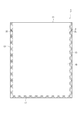
- FIG. 1 is a plan view showing a packaging bag in the first embodiment.
- FIG. 2 is a cross-sectional view of the packaging bag in the first embodiment.
- the packaging bag 1 includes a male side belt-like member 21 as a male side tape 21 having a male side occlusal portion 21 ⁇ / b> A on a single base film 10 that is a packaging bag film, and a female side.
- the female side belt-like member 22 as the female side tape having the occlusal portion 22A is bonded to each other.
- the male occlusion portion 21A and the female occlusion portion 22A can be occluded, and the occlusion portion 23 is configured by occlusion.
- the male side belt-like member 21 and the female side belt-like member 22 constitute the zipper tape 2.
- the base film 10 has a bottom seal portion 17 in which one base end 11 is overlapped with the other base end 11. Further, side seal portions 13 in which the respective base film 10 is heat-sealed are respectively provided at both end portions of the base film 10. Between these side seal portions 13, a male side belt-like member 21 and a female side belt-like member 22 are disposed along the opening edge on the opposite side to the bottom seal portion 17. Further, the female side belt-like member 22 located in the side seal portion 13 is provided with a missing portion 25 as shown in FIG. Due to the missing portion 25, the female side occlusal portion 22A is substantially removed at the position of the side seal portion 13, and since there is no unevenness due to the female side occlusal portion 22A, the side seal portion 13 is well sealed.
- the base film 10 is sealed on three sides of the bottom seal portion 17 and the side seal portion 13, and the accommodation space 14 is formed by the occlusion of the male occlusion portion 21A and the female occlusion portion 22A.
- the storage space 14 can store solids, powders, liquids, and the like.
- the base film 10 has a male side belt-like member 21 and a female side belt-like member 22 heat-sealed on the inner surface 10A thereof.
- the base film 10 is not particularly limited as long as it is a packaging bag material, and the thickness dimension is preferably 10 ⁇ m or more and 200 ⁇ m or less.
- the thickness dimension is less than 10 ⁇ m, the seal strength and the bag strength may be weakened.
- the thickness dimension exceeds 200 ⁇ m, it may be difficult to open the bag.
- the base film 10 may have a single layer structure or a multilayer structure.
- the male side band-shaped member 21 has a long side band-shaped male side band-shaped base part 21B.
- the male side band-shaped base part 21B has a surface on the accommodation space 14 side and is positioned at a substantially intermediate part in the width direction along the longitudinal direction. A male occlusal portion 21A is projected.
- the female side belt-like member 22 has a female side belt-like base portion 22B, and the female side belt-like base portion 22B has a rib-shaped female side occlusion portion that can be engaged with the male occlusal portion 21A on the surface on the accommodation space 14 side. 22A is protruding.
- the width dimension of the male side belt-like base portion 21B and the female side belt-like base portion 22B is preferably 2 mm or more and 50 mm or less, and more preferably 5 mm or more and 20 mm or less.
- the thickness dimension of the male side belt-like base portion 21B and the female side belt-like base portion 22B is preferably 50 ⁇ m or more and 500 ⁇ m or less, and more preferably 100 ⁇ m or more and 200 ⁇ m or less.
- the opening position of the packaging bag 1 may be on the side of the top seal portion 12 with respect to the position of the occlusion portion 23 constituted by the male occlusion portion 21A and the female occlusion portion 22A. It can be made easy to open by providing a notch or providing an opening tape in the vicinity of the male occlusal portion 21A and the female occlusal portion 22A.
- FIG. 3 is a perspective view showing a packaging bag manufacturing apparatus.
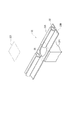
- FIG. 4 is a perspective view showing a situation in which a missing portion is provided in the zipper tape member.
- the manufacturing apparatus 9 is used in a three-sided bag making method, and a tape feeding device 31 that sends out a zipper tape member 211 in which a male side belt-like member 21 and a female side belt-like member 22 are engaged, An occlusion release part 36 for removing the engagement of the zipper tape member 211, a punching device 32 (see FIG.
- the tape feeding device 31 is detachably mounted with a tape take-up roll 312 around which a zipper tape member 211 that engages the male side belt-like member 21 and the female side belt-like member 22 is wound.
- the member 211 is sent out.
- the operation of the zipper tape member 211 is not limited to a configuration in which the zipper tape member 211 is continuously supplied at a constant speed, and any operation method such as a configuration in which the zipper tape member 211 is intermittently supplied can be applied. Note that FIG. 3 shows only one of the pair of tape operation devices 31 for convenience of explanation.
- the occlusal release unit 36 includes a rotatable occlusion release roller 361 and hangs over the outer peripheral surface of the occlusion release roller 361 in a state where the male side belt-like member 21 and the female side belt-like member 22 are separated from each other.
- the punching device 32 has a mold 321 as shown in FIG.
- the punching device 32 is provided only on the female side belt-like member 22 out of the male side belt-like member 21 and the female side belt-like member 22 fed out from the tape steering device 31, and at least of the female-side occlusion portion 22A at a predetermined interval in the steering direction.
- the punched portion 25 is punched by the mold 321 at the position, and the missing portion 25 is formed. That is, the missing portions 25 are formed at a predetermined interval corresponding to the position of the side seal portion 13.
- the punching device 32 is not limited to press working, and any configuration that removes at least the female occlusal portion 22A such as heat crushing or excision can be used.
- the re-occlusion portion 37 has a pair of occlusal rollers 371 for re-engaging the male side belt-like member 21 and the female side belt-like member 22 having the missing portion 25.
- the re-engagement part 37 sandwiches the male side belt-like member 21 and the female side belt-like member 22 between the occlusion rollers 371 and re-engages them.
- the zipper tape bonding apparatus 81 heat seals the re-engaged zipper tape 2 to the base film 10 fed out from the film take-up roll 101.
- the seal bar 82 heat-seals the substrate end portion 11 of the substrate film 10 to form the bottom seal portion 17.
- the side seal bar 84 heat seals the base end portion 11 of the base film 10 to form the side seal portion 13.
- the cutting part 75 cuts in the middle position of the side seal part 13, and cuts out the packaging bag 1 in which the three sides of the bottom seal part 17 and the side seal part 13 are heat-sealed.
- the manufacturing method of the packaging bag 1 includes a tape operation step for feeding out the male side belt-like member 21 and the female side belt-like member 22, and a punching step as a missing portion forming step for punching and forming the missing portion 25 only in the female side belt-like member 22.
- a zipper tape attaching process for bonding the zipper tape 2 to the base film 10 and a bag making process for forming the packaging bag 1 from the base film 10 are performed.
- the male belt-like member 21 and the female side are engaged by the occlusion release roller 361 of the occlusion release portion 36.
- the occlusion of the belt-shaped member 22 is released and the punching process is performed.
- the missing portions 25 are punched and formed at predetermined intervals by the mold 321 only in the female occlusal portion 22A out of the fed male occlusal portion 21A and female occlusal portion 22A.
- the male occlusal portion 21A and the female occlusion portion 22A that are further extended are re-engaged with the male side belt-like member 21 and the female side belt-like member 22 sandwiched between the occlusal rollers 371 of the re-occlusion portion 37.
- the zipper tape 2 re-engaged by the zipper tape bonding device 81 is heat sealed to the base film 10.
- the base end portion 11 of the base film 10 is heat sealed by the seal bar 82 to form the bottom seal portion 17, and the side seal bar 84 is the base end portion of the base film 10.
- 11 is heat-sealed to form a side seal portion 13.
- the cutting part 75 cut disconnects in the intermediate position of the side seal part 13, and cuts out the packaging bag 1 by which the three sides of the bottom seal part 17 and the side seal part 13 were heat-sealed.
- a predetermined amount of the content is put into the obtained packaging bag 1 by a filling device (not shown), and the packaging bag 1 is filled with the content.
- a good sealing state of the zipper tape 2 can be obtained up to the position of the side seal portion 13 at the heat welding position, and the thickness dimension of the occlusal portion 23 can be suppressed by the missing portion 25, for example, the aluminum layer is broken. This can prevent the base film 10 from being damaged. Further, when the male occlusion portion 21A and the female occlusion portion 22A are occluded by the re-occlusion portion 37, the male occlusion portion 21A without the missing portion 25 serves as a guide for occlusion, and a reliable occlusion state can be easily obtained. Easy to make bags.
- the missing portion 25 is formed by punching. For this reason, when a part of the female occlusal portion 22A located at the edge of the missing portion 25 is crushed during heat sealing, the majority flows into the missing portion 25 and becomes thick at the position of the side seal portion 13. Can be further suppressed. Therefore, a reliable sealing state with the zipper tape 2 can be obtained, and even if a laminated film having an aluminum layer is used as the base film 10, the difference in thickness is reduced, so that cracking of the aluminum layer can be prevented, which is good. You can make bags.
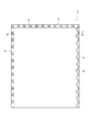
- FIG. 5 is a plan view showing the packaging bag in the second embodiment.
- This 2nd Embodiment manufactures the packaging bag 3 provided with the top seal part 12 instead of the bottom seal part 17 in 1st Embodiment with the vertical pillow-type bag making method.
- the same or similar configurations as those in the first embodiment are denoted by the same reference numerals, and description thereof is omitted or simplified.
- the packaging bag 3 includes a male side band-like member 21 as a male side tape 21 having a male side occlusion portion 21A and a female side occlusion portion on a single base film 10 that is a film for a packaging bag.
- the female side belt-like member 22 as the female side tape having 22A is bonded to each other.
- the male occlusion portion 21A and the female occlusion portion 22A can be occluded, and the occlusion portion 23 is configured by occlusion.
- the male side belt-like member 21 and the female side belt-like member 22 constitute the zipper tape 2.
- the base film 10 has a top seal portion 12 in which one base end 11 is overlapped with the other base end 11.
- side seal portions 13 in which the respective base film 10 is heat-sealed are respectively provided at both end portions of the base film 10.
- a male band member 21 and a female band member 22 are disposed between the side seal portions 13 along the top seal portion 12.
- the female side belt-like member 22 located in the side seal portion 13 is provided with a missing portion 25 as shown in FIG.
- the base film 10 has an accommodation space 14 formed by sealing the three sides of the top seal portion 12 and the side seal portion 13.
- the storage space 14 can store solids, powders, liquids, and the like.
- the base film 10 has a male side belt-like member 21 and a female side belt-like member 22 heat-sealed on the inner surface 10A thereof.
- the opening position of the packaging bag 3 may be on the side of the top seal portion 12 with respect to the position of the occlusion portion 23 constituted by the male occlusion portion 21A and the female occlusion portion 22A. It can be made easy to open by providing a notch or providing an opening tape in the vicinity of the male occlusal portion 21A and the female occlusal portion 22A.
- FIG. 6 is a perspective view showing a packaging bag manufacturing apparatus in the second embodiment.
- FIG. 7 is a perspective view showing a situation in which a missing portion is provided in the zipper tape member.
- the manufacturing apparatus 4 is a so-called vertical pillow type, a tape operation device 31 that feeds out a zipper tape member 311, and a punching device 32 that punches and forms a missing portion 25 in the zipper tape member 311 (see FIG. 7).
- a separation device 33 that separates the zipper tape member 311 into the male side belt member 21 and the female side belt member 22, and a zipper tape bonding device that bonds the male side belt member 21 and the female side belt member 22 to the base film 10 34, a bag making apparatus 35 for forming the packaging bag 3 from the base film 10, and the like.
- the zipper tape member 311 is formed by forming a pair of male occlusal portions 21A and female occlusal portions 22A in a rib shape along the longitudinal direction on a tape 313 having a longitudinal strip shape. Yes. That is, the zipper tape member 311 has a shape in which the male side belt-like member 21 and the female side belt-like member 22 are arranged in parallel on one surface side in the width direction.
- the tape feeding device 31 detachably attaches a tape take-up roll 312 around which the zipper tape member 311 is wound, and manipulates the zipper tape member 311.
- the operation of the zipper tape member 311 is not limited to a configuration in which the zipper tape member 311 is continuously extended at a constant speed, and any operation method such as a configuration in which the zipper tape member 311 is intermittently extended can be applied.
- the punching device 32 has a die 321 as shown in FIG.
- the punching device 32 punches out only the female-side occlusal portion 22A with a die 321 at a predetermined interval in the steering direction by the die 321 to form the missing portion 25. That is, the missing portions 25 are formed at a predetermined interval corresponding to the position of the side seal portion 13.
- the punching device 32 is not limited to pressing, and any configuration that removes only the female occlusal portion 22A can be used.
- the punching device 32 is a post-process of the separation device 33 described later, that is, after the zipper tape member 311 is cut into the male occlusion portion 21A and the female occlusion portion 22A by the separation device 33, the female side is the same as in the first embodiment. It is good also as a structure which provides the missing part 25 only in the occlusal part 22A.
- the separation device 33 includes a cutting member 331 as shown in FIG. Separating device 33 is formed by cutting member 331 between zipper tape member 311 fed out from tape steering device 31 and having a missing portion 25 formed by punching device 32 between male occlusal portion 21A and female occlusal portion 22A in the width direction. Cut and separated into a male side belt-like member 21 having a male side biting portion 21A and a female side belt-like member 22 having a female side biting portion 22A.
- the cutting member 331 may be constituted by a fixed blade or a rotary blade, for example.
- cutting at the center between the male occlusal portion 21A and the female occlusal portion 22A in the width direction means that the male side belt member 21 and the female side belt member 22 in the subsequent step are cut. It is suitable for the positioning of
- the zipper tape bonding apparatus 34 includes a positioning guide portion 341 and a first heat seal portion (not shown).
- the zipper tape adhering device 34 is provided on both sides of the feeding direction, which is the longitudinal direction of the base film 10 fed from the film take-up roll 101, on the male side belt-like member 21 and the female side in a state along the side edges by the positioning guide portions 341.
- Each of the belt-like members 22 is positioned. Then, the zipper tape bonding apparatus 34 heat-seals the positioned male-side belt-like member 21 and female-side belt-like member 22 to the base film 10 by the first heat seal portion.
- the positioning guide portion 341 is not limited to the case where a roller 343 having a concave portion corresponding to the male occlusion portion 21A or the female occlusion portion 22A as shown in FIG. Any configuration capable of positioning while feeding the side band member 21 and the female side band member 22 can be used.
- the adhesion to the base film 10 is not limited to heat sealing, and various methods such as ultrasonic welding and adhesion using an adhesive can be used.
- the bag making apparatus 35 includes a cylindrical former 351 around which a base film 10 to which a male side belt-like member 21 and a female side belt-like member 22 which are zipper tapes 2 are respectively wound is wound. 351, a feed belt 352 disposed on the side of the 351, an occlusion member 353 for engaging the male occlusal portion 21A and the female occlusion portion 22A, and heat sealing the both sides of the base film 10 to form the top seal portion 12 A seal bar 354 to be formed, a side seal bar 355 as a side seal forming part for forming the side seal part 13 by heat sealing, a cutting part 356 for cutting at the position of the side seal part 13 to obtain the packaging bag 3; Etc.
- the cylindrical former 351 is formed in a hollow shape, and the contents X are put into the packaging bag 3 through the internal space.
- the occlusal member 353 engages the male occlusal portion 21A and the female occlusion portion 22A facing each other by winding the base film 10 around the cylindrical former 351 and overlapping both sides.
- the manufacturing method of the packaging bag 3 includes a tape operation step for feeding out the zipper tape member 311, a punching step as a missing portion forming step for punching and forming the missing portion 25 only in the female belt-like member 22 of the zipper tape member 311, A zipper tape attaching step for bonding the tape 2 to the base film 10 and a bag making step for forming the packaging bag 3 from the base film 10 are performed.
- the zipper tape member 311 is pulled out from the tape take-up roll 312 and fed to the punching process. Then, in the punching process, the missing portions 25 are punched and formed at predetermined intervals only on the female side belt-like member 22 of the zipper tape member 311 that has been fed out. Thereafter, the zipper tape member 311 fed out and punched out is separated into the male side belt-like member 21 and the female side belt-like member 22 using the cutting member 331. Then, the separated male side belt-like member 21 and female side belt-like member 22 are placed on both sides of the base film 10 fed out by the positioning guide portion 341 in the zipper tape attaching step, on the male side belt-like base portion 21B and the female side belt-like base portion 22B. Positioning. In this state, the positioned male-side belt-like member 21 and female-side belt-like member 22 are heat-sealed to the base film 10 by the first heat seal portion.
- the base film 10 is wound around the cylindrical former 351, and the male occlusion portion 21A and the female occlusion portion 22A are engaged with the occlusion member 353, and then the base film 10 is sealed with the seal bar 354.
- the top seal portion 12 is formed by heat-sealing the overlapping side edges.
- heat sealing is performed in a direction perpendicular to the direction of operation of the base film 10 by the side seal bar 355, which is a side seal forming step, one side seal portion 13 is formed, and the packaging bag 3 is Finalize.
- the position to be heat-sealed is the position of the missing portion 25 provided in advance on the female side belt-like member 22.
- a part of the female occlusal portion 22A located at the edge of the missing portion 25 is also heat sealed so that a reliable sealing state by the zipper tape 2 is obtained.
- Most of the female occlusal portion 22A crushed by this heat seal flows into the adjacent missing portion 25, and it is suppressed from becoming thick at the position of the side seal portion 13. That is, in order to obtain a reliable sealing state, it is necessary to crush some of the female-side occlusal portions 22A, but the amount of resin to be crushed flows into the missing portion 25 formed by punching. For this reason, it is suppressed that the difference of the thickness of the part in which the zipper tape 2 is located in the position of the side seal part 13 and the part which is not located becomes large.
- the side seal bar 355 is formed to enclose the contents X, cut at an intermediate position of the side seal part 13, and the contents X are filled into the packaging bag 3.
- the male occlusal portion 21A without the missing portion 25 serves as a guide for occlusion in the bag making process, a reliable occlusal state between the male occlusal portion 21A and the female occlusal portion 22A can be easily obtained. Can make bags.
- the missing portion 25 is provided in the integrated zipper tape member 311 before the integrated zipper tape member 311 is divided into the male side band member 21 and the female side band member 22 and separated. For this reason, the missing portion 25 can be processed and formed in a wide state, and the missing portion 25 can be easily provided without causing inconvenience such as the female side band-like member 22 being cut due to stress during processing. .
- the zipper tape member 311 is cut by the cutting member 331 and separated into the male side band member 21 and the female side band member 22.
- the pulling force acting on the male side belt-like member 21 and the female side belt-like member 22 is relatively small, and the male side belt-like member 21 and the female side belt-like member 22 extend even in the configuration of cutting after having the missing portion 25. Inconvenience such as can be prevented. Therefore, a positional shift between the missing portion 25 provided on the female side belt-like member 22 and the side seal portion 13 does not occur, and heat sealing can be appropriately performed at the position of the missing portion 25.
- FIG. 8 is a perspective view showing a packaging bag manufacturing apparatus in the third embodiment.
- FIG. 9 is a perspective view showing a situation where a missing portion is provided in the zipper tape member.
- This third embodiment relates to a vertical pillow type bag making method as in the second embodiment. Instead of the configuration in which the zipper tape member 311 in the second embodiment is cut by the cutting member 331, the zipper tape member 411 is used. Is torn in a state that bisects in the width direction.
- the same or similar configurations as those in the above-described embodiments are denoted by the same reference numerals, and description thereof is omitted or simplified.
- the manufacturing apparatus 5 of the third embodiment is a tearing separation device 43 instead of the separation device 33 in the second embodiment, and the zipper tape 2 obtained by the separation device 43 instead of the zipper tape bonding device 34 in the second embodiment. Is formed into a zipper tape bonding apparatus 44 for heat-sealing to the base film 10.
- the zipper tape member 411 has a thin portion 412 formed along the longitudinal direction between the male occlusion portion 21A and the female occlusion portion 22A of the zipper tape member 311 in the second embodiment. ing. Instead of the thin portion 412, a cut dotted line perforation such as a so-called perforation may be provided, or the thin portion 412 and the perforation may be used in combination.
- the separation device 43 separates the zipper tape member 411 into a state of tearing at the position of the thin portion 412. Specifically, as shown in FIG. 8, the separating device 43 includes a pair of gripping rollers 431 that sandwich the zipper tape member 411 and a male belt-like strip that is positioned downstream of the gripping roller 431 in the operation direction.
- the tearing roller 432 applies tension in the opposite direction in the thickness direction on both sides in the longitudinal direction of the zipper tape member 411, and is separated so as to tear the male side belt member 21 and the female side belt member 22 at the position of the thin portion 412.
- the tearing roller 432 reverses the torn male side band member 21 or the female side band member 22 so that the male occlusion part 21A and the female occlusion part 22A face each other, and the male side band member 21 and the female side band member Each of the 22 is overlaid.
- the male occlusion portion 21A and the female occlusion portion 22A face each other in a state where both are twisted by 90 ° in the opposite direction. It is good.
- the equivalent twist acts on both the male side belt-like member 21 and the female side belt-like member 22, it is possible to surely prevent a difference in the operation state and to satisfactorily bond the zipper tape 2 .
- the male side belt-like member 21 and the female side belt-like member 22 may be bonded to the base film 10 by the zipper tape bonding device 44 in a later step without being engaged.
- the missing portion 25 may be provided only in the female side belt-like member 22.
- the zipper tape bonding apparatus 44 includes a second heat seal part 442.
- the zipper tape adhering device 44 is a zipper fed from the separating device 43 between the overlapping portions on both sides in the feeding direction of the base film 10 fed from the film take-up roll 101 and wound on the cylindrical former 351 of the bag making device 45. Tape 2 is interposed. Thereafter, the zipper tape 2 is heat sealed to the base film 10 at the second heat seal portion 442.
- various methods such as not only heat sealing but also welding using ultrasonic waves and bonding using an adhesive can be used.
- the bag making apparatus 45 includes a cylindrical former 351 around which the base film 10 is wound, a feed belt 352 disposed on a side portion of the cylindrical former 351, and both sides of the base film 10 to heat-seal the top seal portion. 12, a seal bar 354 that forms the side seal part 13 by heat sealing, a cutting part 356 that cuts at the position of the side seal part 13 to obtain the packaging bag 3, and the like. Yes.
- the manufacturing method of the packaging bag 3 using the manufacturing apparatus 5 is demonstrated.
- the zipper tape member 411 fed out and punched out is separated into the male side belt-like member 21 and the female side belt-like member 22 so as to be torn at the position of the thin portion 412 in the separation step.
- the male occlusion portion 21A and the female occlusion portion 22A are engaged to form a pair of zipper tapes 2.
- the zipper tape 2 is bonded to both side portions of the base film 10 wound around the cylindrical former 351 in the bonding process, and bag making is performed.
- the missing portion 25 is provided only in the female side belt-like member 22 of the zipper tape member 411 and then separated into the male side belt-like member 21 and the female side belt-like member 22, the same as in the second embodiment.
- a good sealing state can be easily obtained without impairing the properties of the base film 10.
- the separating device 43 includes the tearing roller 432 that tears at the position of the thin portion 412 provided on the zipper tape member 411, the member is compared with the case of using the cutting member 331 shown in the second embodiment. Maintenance associated with replacement is unnecessary, and productivity can be improved.
- FIG. 10 is a plan view showing a packaging bag in the fourth embodiment.
- FIG. 11 is a cross-sectional view of the packaging bag in the fourth embodiment.
- a zipper tape bonding apparatus 64 instead of the bag making apparatus 35 having the cylindrical former 351 in the second embodiment, a zipper tape bonding apparatus 64 having a rotating drum 641 is used as shown in FIG. It is.
- the same or similar configurations as those in the above embodiments are denoted by the same reference numerals, and description thereof is omitted or simplified.
- the packaging bag 6 includes a single base film 10, a male side belt-like member 21 having a male side biting portion 21 ⁇ / b> A, and a female side belt-like member 22 having a female side biting portion 22 ⁇ / b> A.
- the male side belt member 21 and the female side belt member 22 constitute a zipper tape 2.
- the base film 10 has a back pasting portion 16 in which one base end 11 is overlapped with the other base end 11. Further, side seal portions 13 in which the respective base film 10 is heat-sealed are respectively provided at both end portions of the base film 10. Between the side seal portions 13, a male side belt member 21 and a female side belt member 22 are disposed. An accommodation space 14 is formed in the base film 10 by the back pasting portion 16 and the side seal portion 13. A gusset 15 is formed on the bottom of the base film 10.
- FIG. 12 is a perspective view showing a packaging bag manufacturing apparatus in the fourth embodiment.
- the manufacturing apparatus 7 includes a tape operating device 31 that feeds out the zipper tape member 311, a punching device 32 that punches and forms the missing portion 25 only in the female belt-like member 22 of the zipper tape member 311, Separating device 33 for separating tape member 311 into male belt member 21 and female belt member 22, zipper tape bonding device 64 for bonding male belt member 21 and female belt member 22 to base film 10, A bag making device 65 for forming the packaging bag 6 from the material film 10, a bending member feeding device 66 for feeding the bending member 24, and the like are provided.
- Reference numeral 643 denotes a guide roll.
- the missing portion 25 may be provided only in the female side belt-like member 22 after being separated by the separation device 33.
- the zipper tape bonding apparatus 64 includes a substantially cylindrical rotating drum 641 rotated by a drive source (not shown) and a curved fusion surface 642A corresponding to the peripheral surface shape of the rotating drum 641. And a seal bar 642.
- the rotating drum 641 is provided with a first groove 641A for introducing and guiding the male occlusal portion 21A and a second groove 641B for introducing and guiding the female occlusal portion 22A, respectively, along the circumferential direction.
- Each of the groove portions 641A and 641B has a substantially rectangular cross section having a size capable of accommodating the male side belt-like member 21 and the female side belt-like member 22, and the bottom surface thereof is substantially parallel to the peripheral surface of the rotating drum 641.
- the side surfaces facing each other are formed to have substantially the same length as the protruding dimensions of the male side belt-like member 21 and the female side belt-like member 22.
- the first groove portion 641A and the second groove portion 641B are configured such that the bending member 24 is disposed between the male side belt-like base portion 21B and the female side belt-like base portion 22B with a predetermined gap therebetween, and the bending portion 231 of the bending member 24
- the male occlusal portion 21A and the female occlusion portion 22A are provided so as to be able to introduce and guide so that the male occlusion portion 21A and the female occlusion portion 22A can be occluded.
- the rotating drum 641 is preferably supported by a support member in a state where the axial direction is the horizontal direction. This is because it becomes easy to position the male side belt-like member 21 and the female side belt-like member 22 at predetermined positions on the base film 10.
- the bag making apparatus 65 includes a cylindrical former 651 on which the base film 10 to which the zipper tape 2 is fused is wound, a feed belt 652 disposed on the side of the cylindrical former 651, and both bases of the base film 10. Cut at the position of the seal bar 653 that forms the back adhesive part by fusing the material end 11, the side seal bar 654 that forms the side seal part 13, the triangular plate 655 that forms the gusset 15, and the side seal part 13 And a cutting section (not shown) for obtaining the packaging bag 6.
- the manufacturing method of the packaging bag 6 using the manufacturing apparatus 7 is demonstrated.
- the manufacturing method of the packaging bag 6 includes a tape operation step for feeding out the zipper tape member 311, a punching step for punching and forming the missing portion 25 only in the female belt-like member 22 of the zipper tape member 311, and the zipper tape member 311 on the male side Separation step for separating the belt-like member 21 and the female-side belt-like member 22, an adhesion step for bonding the zipper tape 2 to the base film 10, and a bag making step for forming the packaging bag 6 from the base film 10 are performed. To do.
- the zipper tape member 311 is pulled out from the tape take-up roll 312 in the tape operation process. Then, in the punching process, the missing portions 25 are punched and formed at predetermined intervals only on the female side belt-like member 22 of the zipper tape member 311 that has been fed out. Thereafter, in the separation step, the cutting member 331 separates the male side belt-like member 21 and the female side belt-like member 22. Further, the male side belt-like member 21 and the female side belt-like member 22 are sent to the zipper tape bonding device 64 in a state where the male side belt-like member 21 and the female side belt-like member 22 are overlapped with the base film 10 drawn from the film take-up roll 101.
- the bending member 24 is disposed between the male side belt-like base portion 21B and the female side belt-like base portion 22B with a predetermined gap therebetween, together with the male side belt-like member 21 and the female side belt-like member 22.
- the bending member 24 is superposed on the base film 10 and sent to the zipper tape bonding device 64.
- the male side belt-like member 21, the female side belt-like member 22, the bending member 24, and the base film 10 are overlapped by the zipper tape bonding device 64, and the male side belt-like base portion 21B and The female side belt-like base 22B is continuously guided by the rotation of the rotary drum 641 while being guided by the grooves 641A and 641B of the rotary drum 641.
- a seal bar 642 having a curved fusion surface 642A corresponding to the peripheral surface of the rotating drum 641 the male side belt member 21, the female side belt member 22 and the bending member 24 are combined into one sheet. Adhere to the substrate film 10.
- the speed when continuously running by rotation of the rotating drum 641 is preferably 5 m / min or more and 40 m / min or less, and more preferably 10 m / min or more and 30 m / min or less.
- the productivity may be lowered and the cost may be increased.
- the speed exceeds 40 m / min, the seal strength may become unstable.
- the base film 10 to which the zipper tape 2 is fused is sent to the bag making apparatus 65.
- the base film 10 is sent downward by the feed belt 652 while being wound around the cylindrical former 651.
- the missing portion 25 and the side seal portion 13 are sent so as to coincide with each other.
- the back sticking portion is formed by the seal bar 653, and the gusset 15 is formed at the portion corresponding to the bottom by the triangular plate 655.
- one side seal portion 13 is formed by the side seal bar 654.
- the other side seal portion 13 is formed again by the side seal bar 654. And it cut
- the missing portion 25 is provided only in the female side belt-like member 22 of the zipper tape member 311 and then separated into the male side belt-like member 21 and the female side belt-like member 22, the second embodiment and Similar to the third embodiment, a good sealing state of the zipper tape 2 can be obtained up to the position of the side seal portion 13, and a good sealing state can be easily obtained without impairing the characteristics of the base film 10. Furthermore, a positive occlusion state between the male occlusal portion 21A and the female occlusion portion 22A can be easily obtained, and bag making can be easily performed. In addition, the missing portion 25 can be processed and formed in a wide state, and the missing portion 25 can be easily formed. Further, since the zipper tape member 311 is separated by the cutting member 331, the misalignment between the missing portion 25 of the female band-like member 22 and the side seal portion 13 does not occur, and heat sealing can be appropriately performed at the position of the missing portion 25. .
- FIG. 13 is a perspective view which shows the manufacturing apparatus of the packaging bag in 5th Embodiment.
- a separating device 43 that tears the zipper tape member 411 in the third embodiment into two in the width direction is used. It is.
- the same or similar configurations as those in the above-described embodiments are denoted by the same reference numerals, and description thereof is omitted or simplified.
- This Embodiment 5 also has the same effects as the above-described embodiment.
- the present invention is not limited to the above-described embodiments, and modifications, improvements, and the like within the scope that can achieve the object of the present invention are included in the present invention.
- the configuration in which the contents X are automatically filled when the packaging bags 1 and 3 are made is illustrated.
- the structure of bag making may be changed according to the contents to be sealed, such as sealing with a heat seal or sealing the opening with a zipper tape instead of heat seal as in a futon bag.
- the present invention may be applied to a three-sided bag made by heat-sealing portions corresponding to the side and bottom surfaces of the packaging bag, and a three-side bag made by heat-sealing portions corresponding to the side and opening surfaces of the packaging bag.
- it may be applied to a packaging bag having gussets on the side and bottom.
- a bag making method in addition to the vertical pillow type of the second and third embodiments, the rotary drum type of the fourth embodiment, the three-side bag making of the first and fifth embodiments, various bag making methods Applicable.
- the missing portion 25 is formed by punching, but may be formed by any method capable of removing the occlusal portion, such as cutting or heat crushing. Further, the omission portion 25 may be formed by removing only the occlusal portion while leaving the band-shaped base portion.
- the male side belt-like member 21 and the female side belt-like member 22 were separated after providing the lacking portion 25 in the female side belt-like member 22 of the zipper tape members 311 and 411. 25 may be provided.
- the configuration in which the male occlusal portion 21A and the female occlusal portion 22A are provided in parallel on one side (same surface) side in the width direction is exemplified, but for example, both sides in the width direction (different surfaces)
- a male occlusal portion 21A and a female occlusal portion 22A may be provided respectively. In this configuration, it is not necessary to invert the male occlusal portion 21A and the female occlusal portion 22A to face each other after separation, and the productivity can be improved.
- the bending member 24 has been described.
- the present invention is not limited to this configuration.
- one edge of the male side belt-like base portion 21B and one edge of the female side belt-like base portion 22B are substantially brought into contact with each other. It is good also as a structure which guides introduction in a state.
- the male side belt-like base portion 21B and the female side belt-like base portion 22B can be easily positioned without using the bending member 24, and a configuration that can be reliably re-engaged after opening is easily obtained.
- the missing portion 25 is provided only in the female band-like member 22.
- the present invention can be used for, for example, a zipper tape used for a packaging bag with a zipper tape for packaging various articles such as foods, medicines, medical products, and miscellaneous goods, a packaging bag with this zipper tape, a manufacturing method thereof, and a manufacturing apparatus thereof. .
Landscapes
- Engineering & Computer Science (AREA)
- Mechanical Engineering (AREA)
- Making Paper Articles (AREA)
- Bag Frames (AREA)
- Slide Fasteners (AREA)
Priority Applications (3)
| Application Number | Priority Date | Filing Date | Title |
|---|---|---|---|
| EP10823409.7A EP2489284A4 (en) | 2009-10-14 | 2010-10-13 | ZIP, PACKAGING BAG WITH THE ZIPPER, METHOD FOR PRODUCING THE PACKAGING BAG WITH THE ZIPPER AND DEVICE FOR PRODUCING THE SAME |
| CN2010800463709A CN102686121A (zh) | 2009-10-14 | 2010-10-13 | 卡扣带、带有卡扣带的包装袋、带有卡扣带的包装袋的制造方法及其制造装置 |
| US13/501,889 US20120201480A1 (en) | 2009-10-14 | 2010-10-13 | Zipper tape, packaging bag with zipper tape, method for producing packaging bag with zipper tape and production device therefor |
Applications Claiming Priority (2)
| Application Number | Priority Date | Filing Date | Title |
|---|---|---|---|
| JP2009-237529 | 2009-10-14 | ||
| JP2009237529A JP2011083378A (ja) | 2009-10-14 | 2009-10-14 | ジッパーテープ、ジッパーテープ付包装袋、ジッパーテープ付包装袋の製造方法およびその製造装置 |
Publications (1)
| Publication Number | Publication Date |
|---|---|
| WO2011046141A1 true WO2011046141A1 (ja) | 2011-04-21 |
Family
ID=43876190
Family Applications (1)
| Application Number | Title | Priority Date | Filing Date |
|---|---|---|---|
| PCT/JP2010/067953 Ceased WO2011046141A1 (ja) | 2009-10-14 | 2010-10-13 | ジッパーテープ、ジッパーテープ付包装袋、ジッパーテープ付包装袋の製造方法およびその製造装置 |
Country Status (7)
| Country | Link |
|---|---|
| US (1) | US20120201480A1 (https=) |
| EP (1) | EP2489284A4 (https=) |
| JP (1) | JP2011083378A (https=) |
| KR (1) | KR20120084726A (https=) |
| CN (1) | CN102686121A (https=) |
| TW (1) | TW201127704A (https=) |
| WO (1) | WO2011046141A1 (https=) |
Cited By (3)
| Publication number | Priority date | Publication date | Assignee | Title |
|---|---|---|---|---|
| CN103764510A (zh) * | 2011-09-30 | 2014-04-30 | 出光统一科技株式会社 | 形状保持带、卡扣带、包装袋、形状保持带的制造方法以及卡扣带的制造方法 |
| JP2017136832A (ja) * | 2016-01-29 | 2017-08-10 | 出光ユニテック株式会社 | 袋体の製造方法、および、その製造装置、ならびに袋体 |
| CN107428089A (zh) * | 2015-04-08 | 2017-12-01 | 出光统科技株式会社 | 卡扣带、带有卡扣带的袋体及带有卡扣带的袋体的制造方法、以及能够良好地接合长条构件的长条构件的接合方法、其装置及卡扣带的接合装置 |
Families Citing this family (15)
| Publication number | Priority date | Publication date | Assignee | Title |
|---|---|---|---|---|
| JP6060148B2 (ja) * | 2012-02-28 | 2017-01-11 | 株式会社タカゾノ | 錠剤包装装置及び包装袋 |
| EP3013163B2 (en) | 2013-06-24 | 2022-03-09 | Sluis Cigar Machinery B.V. | Device for welding a zip seal in a tobacco pouch |
| CN104593225A (zh) * | 2013-10-30 | 2015-05-06 | 刘建华 | 长条形脱水编织袋 |
| JP6487257B2 (ja) * | 2015-03-31 | 2019-03-20 | 出光ユニテック株式会社 | ジッパーテープ体およびジッパーテープ付袋体の製造方法 |
| JP6487256B2 (ja) * | 2015-03-31 | 2019-03-20 | 出光ユニテック株式会社 | ジッパーテープ付袋体の製造方法 |
| US10493715B2 (en) * | 2015-06-11 | 2019-12-03 | Totani Corporation | Apparatus and method for making plastic bags |
| US10633137B2 (en) | 2015-11-16 | 2020-04-28 | Automated Packaging Systems, Llc | Method of forming packages from a web of preformed bags |
| JP6871771B2 (ja) * | 2017-03-22 | 2021-05-12 | 出光ユニテック株式会社 | 梱包体、梱包方法、および取付装置 |
| US11542065B2 (en) | 2017-12-08 | 2023-01-03 | Idemitsu Unitech Co., Ltd. | Bag with attached zipper tape, manufacturing method of bag with attached zipper tape |
| JP6539762B2 (ja) * | 2018-04-19 | 2019-07-03 | 株式会社生産日本社 | 製品入り外袋の巻き取り品又はつづら折り品、それらの製造方法及び袋体の供給方法 |
| WO2021144690A1 (en) * | 2020-01-16 | 2021-07-22 | 3M Innovative Properties Company | Tooling fixture |
| JP7479890B2 (ja) * | 2020-03-27 | 2024-05-09 | 日清食品ホールディングス株式会社 | 包装箱のブランクシート及びその包装箱 |
| EP4132854A4 (en) * | 2020-04-06 | 2024-06-12 | Lohia Corp Limited | APPARATUS AND METHOD FOR SEALING OPEN ENDS OF BAGS BY EASY-OPEN SEWING AND EASY-OPEN SEWING BAG |
| DE102022111776A1 (de) | 2022-05-11 | 2023-04-13 | Syntegon Technology Gmbh | Verpackungsbearbeitungsvorrichtung für eine Verpackungsmaschine, Verpackungsmaschine mit einer Verpackungsbearbeitungsvorrichtung sowie Verfahren zu einem Bearbeiten einer Verpackung oder eines Verpackungsmaterials |
| JP7676647B1 (ja) * | 2024-10-03 | 2025-05-14 | 進一 塚本 | 袋の開け口 |
Citations (7)
| Publication number | Priority date | Publication date | Assignee | Title |
|---|---|---|---|---|
| US3847711A (en) * | 1972-02-11 | 1974-11-12 | Uly Pak Inc | Heat-sealing system for plastic containers |
| JPS6410178B2 (https=) * | 1985-12-28 | 1989-02-21 | Nippon Totsukyo Kanri Kk | |
| JPH0632305A (ja) | 1992-07-06 | 1994-02-08 | Sanwa Jidoki Seisakusho:Kk | 製袋充填方法及び装置 |
| JPH0655674A (ja) | 1992-08-10 | 1994-03-01 | Showa Highpolymer Co Ltd | チャック付テープ及びチャック付袋の製法 |
| JP2003276099A (ja) | 2002-03-25 | 2003-09-30 | Kanro Kk | チャック付袋体の製造方法 |
| JP2006087452A (ja) * | 2004-09-21 | 2006-04-06 | Dainippon Printing Co Ltd | チャックテープおよびチャックテープ付き袋 |
| JP2008179035A (ja) * | 2007-01-24 | 2008-08-07 | Tokyo Autom Mach Works Ltd | ジッパ端部形成装置 |
Family Cites Families (16)
| Publication number | Priority date | Publication date | Assignee | Title |
|---|---|---|---|---|
| US3380481A (en) * | 1962-03-02 | 1968-04-30 | Minigrip Inc | Closed tube with fastener members |
| JPS62196131A (ja) * | 1986-02-21 | 1987-08-29 | 日本特許管理株式会社 | チヤツク付袋の製法 |
| JPS6458610A (en) * | 1987-08-17 | 1989-03-06 | Nihon Tokkyo Kanri Co Ltd | Bag form-fill-sealing method |
| JPH0317048U (https=) * | 1989-07-03 | 1991-02-20 | ||
| US5273511A (en) * | 1993-03-30 | 1993-12-28 | Illinois Tool Works Inc. | Method to improve welding of profiled plastic film or tape |
| US5878468A (en) * | 1996-05-22 | 1999-03-09 | Reynolds Consumer Products, Inc. | Closure arrangement for reclosable bag and method thereof |
| US7041249B2 (en) * | 1999-10-12 | 2006-05-09 | Com-Pac International | Vibratory molding process and product |
| US6470551B1 (en) * | 2000-08-10 | 2002-10-29 | Pactiv Corporation | Method of making a fasteners arrangement with notches at spaced preseals |
| US6569368B2 (en) * | 2001-07-31 | 2003-05-27 | Illinois Tool Works Inc. | Method for manufacturing a plastic zipper with end stops |
| JP2007501175A (ja) * | 2003-05-19 | 2007-01-25 | エス. シー. ジョンソン ホーム ストレージ インコーポレイテッド | 開閉自在パウチのための閉止装置 |
| US20040234171A1 (en) * | 2003-05-19 | 2004-11-25 | Dais Brian C. | Reclosable pouch with closure device that allows venting and/or an air-tight seal |
| JP5087219B2 (ja) * | 2005-11-08 | 2012-12-05 | 出光ユニテック株式会社 | 咬合具、これを用いた袋およびこれらの製造方法 |
| JP4874742B2 (ja) * | 2006-08-21 | 2012-02-15 | 出光ユニテック株式会社 | カットテープ付きチャックテープ、その製造方法、およびチャックテープ付き包装袋 |
| EP2103541A4 (en) * | 2006-09-22 | 2014-01-08 | Idemitsu Unitech Co Ltd | EASILY RIVETABLE FASTENING STRIP, METHOD FOR PRODUCING THE FASTENING STRAP, PACKAGING BAG WITH EASILY RIPPABLE FASTENING STRIP AND DEVICE AND METHOD FOR PRODUCING THE PACKAGING BAG |
| CA2816619C (en) * | 2010-11-29 | 2017-01-10 | Illinois Tool Works Inc. | Zipper profile manufactured by cut and stretch methods |
| US8568031B2 (en) * | 2011-02-22 | 2013-10-29 | S.C. Johnson & Son, Inc. | Clicking closure device for a reclosable pouch |
-
2009
- 2009-10-14 JP JP2009237529A patent/JP2011083378A/ja active Pending
-
2010
- 2010-10-13 EP EP10823409.7A patent/EP2489284A4/en not_active Withdrawn
- 2010-10-13 WO PCT/JP2010/067953 patent/WO2011046141A1/ja not_active Ceased
- 2010-10-13 US US13/501,889 patent/US20120201480A1/en not_active Abandoned
- 2010-10-13 KR KR1020127008509A patent/KR20120084726A/ko not_active Withdrawn
- 2010-10-13 CN CN2010800463709A patent/CN102686121A/zh active Pending
- 2010-10-14 TW TW099135096A patent/TW201127704A/zh unknown
Patent Citations (7)
| Publication number | Priority date | Publication date | Assignee | Title |
|---|---|---|---|---|
| US3847711A (en) * | 1972-02-11 | 1974-11-12 | Uly Pak Inc | Heat-sealing system for plastic containers |
| JPS6410178B2 (https=) * | 1985-12-28 | 1989-02-21 | Nippon Totsukyo Kanri Kk | |
| JPH0632305A (ja) | 1992-07-06 | 1994-02-08 | Sanwa Jidoki Seisakusho:Kk | 製袋充填方法及び装置 |
| JPH0655674A (ja) | 1992-08-10 | 1994-03-01 | Showa Highpolymer Co Ltd | チャック付テープ及びチャック付袋の製法 |
| JP2003276099A (ja) | 2002-03-25 | 2003-09-30 | Kanro Kk | チャック付袋体の製造方法 |
| JP2006087452A (ja) * | 2004-09-21 | 2006-04-06 | Dainippon Printing Co Ltd | チャックテープおよびチャックテープ付き袋 |
| JP2008179035A (ja) * | 2007-01-24 | 2008-08-07 | Tokyo Autom Mach Works Ltd | ジッパ端部形成装置 |
Non-Patent Citations (1)
| Title |
|---|
| See also references of EP2489284A4 |
Cited By (5)
| Publication number | Priority date | Publication date | Assignee | Title |
|---|---|---|---|---|
| CN103764510A (zh) * | 2011-09-30 | 2014-04-30 | 出光统一科技株式会社 | 形状保持带、卡扣带、包装袋、形状保持带的制造方法以及卡扣带的制造方法 |
| CN107428089A (zh) * | 2015-04-08 | 2017-12-01 | 出光统科技株式会社 | 卡扣带、带有卡扣带的袋体及带有卡扣带的袋体的制造方法、以及能够良好地接合长条构件的长条构件的接合方法、其装置及卡扣带的接合装置 |
| CN107428089B (zh) * | 2015-04-08 | 2021-02-12 | 出光统一科技株式会社 | 卡扣带及其接合装置、带有卡扣带的袋体及其制造方法 |
| US11370064B2 (en) | 2015-04-08 | 2022-06-28 | Idemitsu Unitech Co., Ltd. | Zipper tape, bag with zipper tape, method for manufacturing bag with zipper tape, long member-bonding method capable of favorably bonding long members, device therefor, and zipper tape-bonding device |
| JP2017136832A (ja) * | 2016-01-29 | 2017-08-10 | 出光ユニテック株式会社 | 袋体の製造方法、および、その製造装置、ならびに袋体 |
Also Published As
| Publication number | Publication date |
|---|---|
| TW201127704A (en) | 2011-08-16 |
| EP2489284A1 (en) | 2012-08-22 |
| EP2489284A4 (en) | 2014-09-03 |
| US20120201480A1 (en) | 2012-08-09 |
| JP2011083378A (ja) | 2011-04-28 |
| KR20120084726A (ko) | 2012-07-30 |
| CN102686121A (zh) | 2012-09-19 |
Similar Documents
| Publication | Publication Date | Title |
|---|---|---|
| WO2011046141A1 (ja) | ジッパーテープ、ジッパーテープ付包装袋、ジッパーテープ付包装袋の製造方法およびその製造装置 | |
| WO2010143566A1 (ja) | ジッパーテープ付包装袋の製造方法およびその製造装置 | |
| JP2011083378A5 (https=) | ||
| JP3965355B2 (ja) | 包装袋及びその製造方法 | |
| US11649090B2 (en) | Bag body provided with zipper tape, bag body, method for producing bag body, and device for producing bag body | |
| JPH0639940A (ja) | 包装材料および包装材料の生産方法 | |
| JP6487215B2 (ja) | ジッパーテープ、ジッパーテープ付袋体、および、ジッパーテープ付袋体の製造方法 | |
| TW201919956A (zh) | 袋體、袋體之製造方法及製造裝置 | |
| JP6178636B2 (ja) | 袋体およびその製造方法 | |
| JP6121039B1 (ja) | 底ガゼット付き袋体の製造方法 | |
| JP2010137866A (ja) | ジッパーテープ付包装袋、その包装袋の製造装置、製造方法及び折曲用帯状部材 | |
| JP6487256B2 (ja) | ジッパーテープ付袋体の製造方法 | |
| JP7612414B2 (ja) | 食品包装体 | |
| JP6487257B2 (ja) | ジッパーテープ体およびジッパーテープ付袋体の製造方法 | |
| US20110243481A1 (en) | Packaging bag with zipper tape, device and method for manufacturing packaging bag, and band-like member for bending | |
| JP2012086491A (ja) | 超音波シール方法及びそれを用いた包装袋の製造方法 | |
| JP2010137867A (ja) | ジッパーテープ付包装袋、その包装袋の製造装置、製造方法及び折曲用帯状部材 | |
| JP2022031066A (ja) | チャック付き包装袋 | |
| JP2008105733A (ja) | 補強部材付き袋とその製造方法 | |
| JP5635651B1 (ja) | 製袋機 | |
| JP2006213368A (ja) | ピロー包装体 | |
| JP2018062350A (ja) | テープ挿入型易開封ガゼット袋 | |
| CN115667083A (zh) | 包装袋 | |
| JP2006082840A (ja) | ピロー包装体 |
Legal Events
| Date | Code | Title | Description |
|---|---|---|---|
| WWE | Wipo information: entry into national phase |
Ref document number: 201080046370.9 Country of ref document: CN |
|
| 121 | Ep: the epo has been informed by wipo that ep was designated in this application |
Ref document number: 10823409 Country of ref document: EP Kind code of ref document: A1 |
|
| WWE | Wipo information: entry into national phase |
Ref document number: 2010823409 Country of ref document: EP |
|
| ENP | Entry into the national phase |
Ref document number: 20127008509 Country of ref document: KR Kind code of ref document: A |
|
| WWE | Wipo information: entry into national phase |
Ref document number: 13501889 Country of ref document: US |
|
| NENP | Non-entry into the national phase |
Ref country code: DE |