WO2010116534A1 - 車両用駆動装置の制御装置 - Google Patents
車両用駆動装置の制御装置 Download PDFInfo
- Publication number
- WO2010116534A1 WO2010116534A1 PCT/JP2009/057404 JP2009057404W WO2010116534A1 WO 2010116534 A1 WO2010116534 A1 WO 2010116534A1 JP 2009057404 W JP2009057404 W JP 2009057404W WO 2010116534 A1 WO2010116534 A1 WO 2010116534A1
- Authority
- WO
- WIPO (PCT)
- Prior art keywords
- power
- input torque
- accelerator
- torque
- automatic transmission
- Prior art date
- Legal status (The legal status is an assumption and is not a legal conclusion. Google has not performed a legal analysis and makes no representation as to the accuracy of the status listed.)
- Ceased
Links
Images





Classifications
-
- B—PERFORMING OPERATIONS; TRANSPORTING
- B60—VEHICLES IN GENERAL
- B60W—CONJOINT CONTROL OF VEHICLE SUB-UNITS OF DIFFERENT TYPE OR DIFFERENT FUNCTION; CONTROL SYSTEMS SPECIALLY ADAPTED FOR HYBRID VEHICLES; ROAD VEHICLE DRIVE CONTROL SYSTEMS FOR PURPOSES NOT RELATED TO THE CONTROL OF A PARTICULAR SUB-UNIT
- B60W30/00—Purposes of road vehicle drive control systems not related to the control of a particular sub-unit, e.g. of systems using conjoint control of vehicle sub-units
- B60W30/18—Propelling the vehicle
- B60W30/19—Improvement of gear change, e.g. by synchronisation or smoothing gear shift
-
- B—PERFORMING OPERATIONS; TRANSPORTING
- B60—VEHICLES IN GENERAL
- B60K—ARRANGEMENT OR MOUNTING OF PROPULSION UNITS OR OF TRANSMISSIONS IN VEHICLES; ARRANGEMENT OR MOUNTING OF PLURAL DIVERSE PRIME-MOVERS IN VEHICLES; AUXILIARY DRIVES FOR VEHICLES; INSTRUMENTATION OR DASHBOARDS FOR VEHICLES; ARRANGEMENTS IN CONNECTION WITH COOLING, AIR INTAKE, GAS EXHAUST OR FUEL SUPPLY OF PROPULSION UNITS IN VEHICLES
- B60K6/00—Arrangement or mounting of plural diverse prime-movers for mutual or common propulsion, e.g. hybrid propulsion systems comprising electric motors and internal combustion engines
- B60K6/20—Arrangement or mounting of plural diverse prime-movers for mutual or common propulsion, e.g. hybrid propulsion systems comprising electric motors and internal combustion engines the prime-movers consisting of electric motors and internal combustion engines, e.g. HEVs
- B60K6/22—Arrangement or mounting of plural diverse prime-movers for mutual or common propulsion, e.g. hybrid propulsion systems comprising electric motors and internal combustion engines the prime-movers consisting of electric motors and internal combustion engines, e.g. HEVs characterised by apparatus, components or means specially adapted for HEVs
- B60K6/36—Arrangement or mounting of plural diverse prime-movers for mutual or common propulsion, e.g. hybrid propulsion systems comprising electric motors and internal combustion engines the prime-movers consisting of electric motors and internal combustion engines, e.g. HEVs characterised by apparatus, components or means specially adapted for HEVs characterised by the transmission gearings
- B60K6/365—Arrangement or mounting of plural diverse prime-movers for mutual or common propulsion, e.g. hybrid propulsion systems comprising electric motors and internal combustion engines the prime-movers consisting of electric motors and internal combustion engines, e.g. HEVs characterised by apparatus, components or means specially adapted for HEVs characterised by the transmission gearings with the gears having orbital motion
-
- B—PERFORMING OPERATIONS; TRANSPORTING
- B60—VEHICLES IN GENERAL
- B60K—ARRANGEMENT OR MOUNTING OF PROPULSION UNITS OR OF TRANSMISSIONS IN VEHICLES; ARRANGEMENT OR MOUNTING OF PLURAL DIVERSE PRIME-MOVERS IN VEHICLES; AUXILIARY DRIVES FOR VEHICLES; INSTRUMENTATION OR DASHBOARDS FOR VEHICLES; ARRANGEMENTS IN CONNECTION WITH COOLING, AIR INTAKE, GAS EXHAUST OR FUEL SUPPLY OF PROPULSION UNITS IN VEHICLES
- B60K6/00—Arrangement or mounting of plural diverse prime-movers for mutual or common propulsion, e.g. hybrid propulsion systems comprising electric motors and internal combustion engines
- B60K6/20—Arrangement or mounting of plural diverse prime-movers for mutual or common propulsion, e.g. hybrid propulsion systems comprising electric motors and internal combustion engines the prime-movers consisting of electric motors and internal combustion engines, e.g. HEVs
- B60K6/42—Arrangement or mounting of plural diverse prime-movers for mutual or common propulsion, e.g. hybrid propulsion systems comprising electric motors and internal combustion engines the prime-movers consisting of electric motors and internal combustion engines, e.g. HEVs characterised by the architecture of the hybrid electric vehicle
- B60K6/44—Series-parallel type
- B60K6/445—Differential gearing distribution type
-
- B—PERFORMING OPERATIONS; TRANSPORTING
- B60—VEHICLES IN GENERAL
- B60K—ARRANGEMENT OR MOUNTING OF PROPULSION UNITS OR OF TRANSMISSIONS IN VEHICLES; ARRANGEMENT OR MOUNTING OF PLURAL DIVERSE PRIME-MOVERS IN VEHICLES; AUXILIARY DRIVES FOR VEHICLES; INSTRUMENTATION OR DASHBOARDS FOR VEHICLES; ARRANGEMENTS IN CONNECTION WITH COOLING, AIR INTAKE, GAS EXHAUST OR FUEL SUPPLY OF PROPULSION UNITS IN VEHICLES
- B60K6/00—Arrangement or mounting of plural diverse prime-movers for mutual or common propulsion, e.g. hybrid propulsion systems comprising electric motors and internal combustion engines
- B60K6/20—Arrangement or mounting of plural diverse prime-movers for mutual or common propulsion, e.g. hybrid propulsion systems comprising electric motors and internal combustion engines the prime-movers consisting of electric motors and internal combustion engines, e.g. HEVs
- B60K6/50—Architecture of the driveline characterised by arrangement or kind of transmission units
- B60K6/54—Transmission for changing ratio
- B60K6/547—Transmission for changing ratio the transmission being a stepped gearing
-
- B—PERFORMING OPERATIONS; TRANSPORTING
- B60—VEHICLES IN GENERAL
- B60L—PROPULSION OF ELECTRICALLY-PROPELLED VEHICLES; SUPPLYING ELECTRIC POWER FOR AUXILIARY EQUIPMENT OF ELECTRICALLY-PROPELLED VEHICLES; ELECTRODYNAMIC BRAKE SYSTEMS FOR VEHICLES IN GENERAL; MAGNETIC SUSPENSION OR LEVITATION FOR VEHICLES; MONITORING OPERATING VARIABLES OF ELECTRICALLY-PROPELLED VEHICLES; ELECTRIC SAFETY DEVICES FOR ELECTRICALLY-PROPELLED VEHICLES
- B60L15/00—Methods, circuits, or devices for controlling the traction-motor speed of electrically-propelled vehicles
- B60L15/20—Methods, circuits, or devices for controlling the traction-motor speed of electrically-propelled vehicles for control of the vehicle or its driving motor to achieve a desired performance, e.g. speed, torque, programmed variation of speed
-
- B—PERFORMING OPERATIONS; TRANSPORTING
- B60—VEHICLES IN GENERAL
- B60L—PROPULSION OF ELECTRICALLY-PROPELLED VEHICLES; SUPPLYING ELECTRIC POWER FOR AUXILIARY EQUIPMENT OF ELECTRICALLY-PROPELLED VEHICLES; ELECTRODYNAMIC BRAKE SYSTEMS FOR VEHICLES IN GENERAL; MAGNETIC SUSPENSION OR LEVITATION FOR VEHICLES; MONITORING OPERATING VARIABLES OF ELECTRICALLY-PROPELLED VEHICLES; ELECTRIC SAFETY DEVICES FOR ELECTRICALLY-PROPELLED VEHICLES
- B60L50/00—Electric propulsion with power supplied within the vehicle
- B60L50/10—Electric propulsion with power supplied within the vehicle using propulsion power supplied by engine-driven generators, e.g. generators driven by combustion engines
- B60L50/16—Electric propulsion with power supplied within the vehicle using propulsion power supplied by engine-driven generators, e.g. generators driven by combustion engines with provision for separate direct mechanical propulsion
-
- B—PERFORMING OPERATIONS; TRANSPORTING
- B60—VEHICLES IN GENERAL
- B60L—PROPULSION OF ELECTRICALLY-PROPELLED VEHICLES; SUPPLYING ELECTRIC POWER FOR AUXILIARY EQUIPMENT OF ELECTRICALLY-PROPELLED VEHICLES; ELECTRODYNAMIC BRAKE SYSTEMS FOR VEHICLES IN GENERAL; MAGNETIC SUSPENSION OR LEVITATION FOR VEHICLES; MONITORING OPERATING VARIABLES OF ELECTRICALLY-PROPELLED VEHICLES; ELECTRIC SAFETY DEVICES FOR ELECTRICALLY-PROPELLED VEHICLES
- B60L50/00—Electric propulsion with power supplied within the vehicle
- B60L50/50—Electric propulsion with power supplied within the vehicle using propulsion power supplied by batteries or fuel cells
- B60L50/60—Electric propulsion with power supplied within the vehicle using propulsion power supplied by batteries or fuel cells using power supplied by batteries
- B60L50/61—Electric propulsion with power supplied within the vehicle using propulsion power supplied by batteries or fuel cells using power supplied by batteries by batteries charged by engine-driven generators, e.g. series hybrid electric vehicles
-
- B—PERFORMING OPERATIONS; TRANSPORTING
- B60—VEHICLES IN GENERAL
- B60W—CONJOINT CONTROL OF VEHICLE SUB-UNITS OF DIFFERENT TYPE OR DIFFERENT FUNCTION; CONTROL SYSTEMS SPECIALLY ADAPTED FOR HYBRID VEHICLES; ROAD VEHICLE DRIVE CONTROL SYSTEMS FOR PURPOSES NOT RELATED TO THE CONTROL OF A PARTICULAR SUB-UNIT
- B60W10/00—Conjoint control of vehicle sub-units of different type or different function
- B60W10/04—Conjoint control of vehicle sub-units of different type or different function including control of propulsion units
- B60W10/08—Conjoint control of vehicle sub-units of different type or different function including control of propulsion units including control of electric propulsion units, e.g. motors or generators
-
- B—PERFORMING OPERATIONS; TRANSPORTING
- B60—VEHICLES IN GENERAL
- B60W—CONJOINT CONTROL OF VEHICLE SUB-UNITS OF DIFFERENT TYPE OR DIFFERENT FUNCTION; CONTROL SYSTEMS SPECIALLY ADAPTED FOR HYBRID VEHICLES; ROAD VEHICLE DRIVE CONTROL SYSTEMS FOR PURPOSES NOT RELATED TO THE CONTROL OF A PARTICULAR SUB-UNIT
- B60W10/00—Conjoint control of vehicle sub-units of different type or different function
- B60W10/10—Conjoint control of vehicle sub-units of different type or different function including control of change-speed gearings
- B60W10/11—Stepped gearings
-
- B—PERFORMING OPERATIONS; TRANSPORTING
- B60—VEHICLES IN GENERAL
- B60W—CONJOINT CONTROL OF VEHICLE SUB-UNITS OF DIFFERENT TYPE OR DIFFERENT FUNCTION; CONTROL SYSTEMS SPECIALLY ADAPTED FOR HYBRID VEHICLES; ROAD VEHICLE DRIVE CONTROL SYSTEMS FOR PURPOSES NOT RELATED TO THE CONTROL OF A PARTICULAR SUB-UNIT
- B60W10/00—Conjoint control of vehicle sub-units of different type or different function
- B60W10/10—Conjoint control of vehicle sub-units of different type or different function including control of change-speed gearings
- B60W10/11—Stepped gearings
- B60W10/115—Stepped gearings with planetary gears
-
- B—PERFORMING OPERATIONS; TRANSPORTING
- B60—VEHICLES IN GENERAL
- B60W—CONJOINT CONTROL OF VEHICLE SUB-UNITS OF DIFFERENT TYPE OR DIFFERENT FUNCTION; CONTROL SYSTEMS SPECIALLY ADAPTED FOR HYBRID VEHICLES; ROAD VEHICLE DRIVE CONTROL SYSTEMS FOR PURPOSES NOT RELATED TO THE CONTROL OF A PARTICULAR SUB-UNIT
- B60W20/00—Control systems specially adapted for hybrid vehicles
-
- F—MECHANICAL ENGINEERING; LIGHTING; HEATING; WEAPONS; BLASTING
- F02—COMBUSTION ENGINES; HOT-GAS OR COMBUSTION-PRODUCT ENGINE PLANTS
- F02D—CONTROLLING COMBUSTION ENGINES
- F02D29/00—Controlling engines, such controlling being peculiar to the devices driven thereby, the devices being other than parts or accessories essential to engine operation, e.g. controlling of engines by signals external thereto
- F02D29/02—Controlling engines, such controlling being peculiar to the devices driven thereby, the devices being other than parts or accessories essential to engine operation, e.g. controlling of engines by signals external thereto peculiar to engines driving vehicles; peculiar to engines driving variable pitch propellers
-
- F—MECHANICAL ENGINEERING; LIGHTING; HEATING; WEAPONS; BLASTING
- F16—ENGINEERING ELEMENTS AND UNITS; GENERAL MEASURES FOR PRODUCING AND MAINTAINING EFFECTIVE FUNCTIONING OF MACHINES OR INSTALLATIONS; THERMAL INSULATION IN GENERAL
- F16H—GEARING
- F16H61/00—Control functions within control units of change-speed- or reversing-gearings for conveying rotary motion ; Control of exclusively fluid gearing, friction gearing, gearings with endless flexible members or other particular types of gearing
- F16H61/04—Smoothing ratio shift
- F16H61/06—Smoothing ratio shift by controlling rate of change of fluid pressure
- F16H61/061—Smoothing ratio shift by controlling rate of change of fluid pressure using electric control means
-
- F—MECHANICAL ENGINEERING; LIGHTING; HEATING; WEAPONS; BLASTING
- F16—ENGINEERING ELEMENTS AND UNITS; GENERAL MEASURES FOR PRODUCING AND MAINTAINING EFFECTIVE FUNCTIONING OF MACHINES OR INSTALLATIONS; THERMAL INSULATION IN GENERAL
- F16H—GEARING
- F16H63/00—Control outputs from the control unit to change-speed- or reversing-gearings for conveying rotary motion or to other devices than the final output mechanism
- F16H63/40—Control outputs from the control unit to change-speed- or reversing-gearings for conveying rotary motion or to other devices than the final output mechanism comprising signals other than signals for actuating the final output mechanisms
- F16H63/50—Signals to an engine or motor
- F16H63/502—Signals to an engine or motor for smoothing gear shifts
-
- B—PERFORMING OPERATIONS; TRANSPORTING
- B60—VEHICLES IN GENERAL
- B60K—ARRANGEMENT OR MOUNTING OF PROPULSION UNITS OR OF TRANSMISSIONS IN VEHICLES; ARRANGEMENT OR MOUNTING OF PLURAL DIVERSE PRIME-MOVERS IN VEHICLES; AUXILIARY DRIVES FOR VEHICLES; INSTRUMENTATION OR DASHBOARDS FOR VEHICLES; ARRANGEMENTS IN CONNECTION WITH COOLING, AIR INTAKE, GAS EXHAUST OR FUEL SUPPLY OF PROPULSION UNITS IN VEHICLES
- B60K1/00—Arrangement or mounting of electrical propulsion units
- B60K1/02—Arrangement or mounting of electrical propulsion units comprising more than one electric motor
-
- B—PERFORMING OPERATIONS; TRANSPORTING
- B60—VEHICLES IN GENERAL
- B60L—PROPULSION OF ELECTRICALLY-PROPELLED VEHICLES; SUPPLYING ELECTRIC POWER FOR AUXILIARY EQUIPMENT OF ELECTRICALLY-PROPELLED VEHICLES; ELECTRODYNAMIC BRAKE SYSTEMS FOR VEHICLES IN GENERAL; MAGNETIC SUSPENSION OR LEVITATION FOR VEHICLES; MONITORING OPERATING VARIABLES OF ELECTRICALLY-PROPELLED VEHICLES; ELECTRIC SAFETY DEVICES FOR ELECTRICALLY-PROPELLED VEHICLES
- B60L2210/00—Converter types
- B60L2210/40—DC to AC converters
-
- B—PERFORMING OPERATIONS; TRANSPORTING
- B60—VEHICLES IN GENERAL
- B60L—PROPULSION OF ELECTRICALLY-PROPELLED VEHICLES; SUPPLYING ELECTRIC POWER FOR AUXILIARY EQUIPMENT OF ELECTRICALLY-PROPELLED VEHICLES; ELECTRODYNAMIC BRAKE SYSTEMS FOR VEHICLES IN GENERAL; MAGNETIC SUSPENSION OR LEVITATION FOR VEHICLES; MONITORING OPERATING VARIABLES OF ELECTRICALLY-PROPELLED VEHICLES; ELECTRIC SAFETY DEVICES FOR ELECTRICALLY-PROPELLED VEHICLES
- B60L2240/00—Control parameters of input or output; Target parameters
- B60L2240/10—Vehicle control parameters
- B60L2240/12—Speed
-
- B—PERFORMING OPERATIONS; TRANSPORTING
- B60—VEHICLES IN GENERAL
- B60L—PROPULSION OF ELECTRICALLY-PROPELLED VEHICLES; SUPPLYING ELECTRIC POWER FOR AUXILIARY EQUIPMENT OF ELECTRICALLY-PROPELLED VEHICLES; ELECTRODYNAMIC BRAKE SYSTEMS FOR VEHICLES IN GENERAL; MAGNETIC SUSPENSION OR LEVITATION FOR VEHICLES; MONITORING OPERATING VARIABLES OF ELECTRICALLY-PROPELLED VEHICLES; ELECTRIC SAFETY DEVICES FOR ELECTRICALLY-PROPELLED VEHICLES
- B60L2240/00—Control parameters of input or output; Target parameters
- B60L2240/40—Drive Train control parameters
- B60L2240/42—Drive Train control parameters related to electric machines
- B60L2240/423—Torque
-
- B—PERFORMING OPERATIONS; TRANSPORTING
- B60—VEHICLES IN GENERAL
- B60L—PROPULSION OF ELECTRICALLY-PROPELLED VEHICLES; SUPPLYING ELECTRIC POWER FOR AUXILIARY EQUIPMENT OF ELECTRICALLY-PROPELLED VEHICLES; ELECTRODYNAMIC BRAKE SYSTEMS FOR VEHICLES IN GENERAL; MAGNETIC SUSPENSION OR LEVITATION FOR VEHICLES; MONITORING OPERATING VARIABLES OF ELECTRICALLY-PROPELLED VEHICLES; ELECTRIC SAFETY DEVICES FOR ELECTRICALLY-PROPELLED VEHICLES
- B60L2240/00—Control parameters of input or output; Target parameters
- B60L2240/40—Drive Train control parameters
- B60L2240/44—Drive Train control parameters related to combustion engines
- B60L2240/443—Torque
-
- B—PERFORMING OPERATIONS; TRANSPORTING
- B60—VEHICLES IN GENERAL
- B60L—PROPULSION OF ELECTRICALLY-PROPELLED VEHICLES; SUPPLYING ELECTRIC POWER FOR AUXILIARY EQUIPMENT OF ELECTRICALLY-PROPELLED VEHICLES; ELECTRODYNAMIC BRAKE SYSTEMS FOR VEHICLES IN GENERAL; MAGNETIC SUSPENSION OR LEVITATION FOR VEHICLES; MONITORING OPERATING VARIABLES OF ELECTRICALLY-PROPELLED VEHICLES; ELECTRIC SAFETY DEVICES FOR ELECTRICALLY-PROPELLED VEHICLES
- B60L2240/00—Control parameters of input or output; Target parameters
- B60L2240/40—Drive Train control parameters
- B60L2240/48—Drive Train control parameters related to transmissions
- B60L2240/486—Operating parameters
-
- B—PERFORMING OPERATIONS; TRANSPORTING
- B60—VEHICLES IN GENERAL
- B60L—PROPULSION OF ELECTRICALLY-PROPELLED VEHICLES; SUPPLYING ELECTRIC POWER FOR AUXILIARY EQUIPMENT OF ELECTRICALLY-PROPELLED VEHICLES; ELECTRODYNAMIC BRAKE SYSTEMS FOR VEHICLES IN GENERAL; MAGNETIC SUSPENSION OR LEVITATION FOR VEHICLES; MONITORING OPERATING VARIABLES OF ELECTRICALLY-PROPELLED VEHICLES; ELECTRIC SAFETY DEVICES FOR ELECTRICALLY-PROPELLED VEHICLES
- B60L2270/00—Problem solutions or means not otherwise provided for
- B60L2270/10—Emission reduction
- B60L2270/14—Emission reduction of noise
- B60L2270/145—Structure borne vibrations
-
- B—PERFORMING OPERATIONS; TRANSPORTING
- B60—VEHICLES IN GENERAL
- B60W—CONJOINT CONTROL OF VEHICLE SUB-UNITS OF DIFFERENT TYPE OR DIFFERENT FUNCTION; CONTROL SYSTEMS SPECIALLY ADAPTED FOR HYBRID VEHICLES; ROAD VEHICLE DRIVE CONTROL SYSTEMS FOR PURPOSES NOT RELATED TO THE CONTROL OF A PARTICULAR SUB-UNIT
- B60W2540/00—Input parameters relating to occupants
- B60W2540/10—Accelerator pedal position
-
- B—PERFORMING OPERATIONS; TRANSPORTING
- B60—VEHICLES IN GENERAL
- B60W—CONJOINT CONTROL OF VEHICLE SUB-UNITS OF DIFFERENT TYPE OR DIFFERENT FUNCTION; CONTROL SYSTEMS SPECIALLY ADAPTED FOR HYBRID VEHICLES; ROAD VEHICLE DRIVE CONTROL SYSTEMS FOR PURPOSES NOT RELATED TO THE CONTROL OF A PARTICULAR SUB-UNIT
- B60W2710/00—Output or target parameters relating to a particular sub-units
- B60W2710/10—Change speed gearings
- B60W2710/1022—Input torque
-
- F—MECHANICAL ENGINEERING; LIGHTING; HEATING; WEAPONS; BLASTING
- F02—COMBUSTION ENGINES; HOT-GAS OR COMBUSTION-PRODUCT ENGINE PLANTS
- F02D—CONTROLLING COMBUSTION ENGINES
- F02D41/00—Electrical control of supply of combustible mixture or its constituents
- F02D41/02—Circuit arrangements for generating control signals
- F02D41/021—Introducing corrections for particular conditions exterior to the engine
- F02D41/0215—Introducing corrections for particular conditions exterior to the engine in relation with elements of the transmission
- F02D41/0225—Introducing corrections for particular conditions exterior to the engine in relation with elements of the transmission in relation with the gear ratio or shift lever position
-
- F—MECHANICAL ENGINEERING; LIGHTING; HEATING; WEAPONS; BLASTING
- F02—COMBUSTION ENGINES; HOT-GAS OR COMBUSTION-PRODUCT ENGINE PLANTS
- F02D—CONTROLLING COMBUSTION ENGINES
- F02D41/00—Electrical control of supply of combustible mixture or its constituents
- F02D41/30—Controlling fuel injection
- F02D41/3011—Controlling fuel injection according to or using specific or several modes of combustion
- F02D41/3064—Controlling fuel injection according to or using specific or several modes of combustion with special control during transition between modes
- F02D41/307—Controlling fuel injection according to or using specific or several modes of combustion with special control during transition between modes to avoid torque shocks
-
- F—MECHANICAL ENGINEERING; LIGHTING; HEATING; WEAPONS; BLASTING
- F16—ENGINEERING ELEMENTS AND UNITS; GENERAL MEASURES FOR PRODUCING AND MAINTAINING EFFECTIVE FUNCTIONING OF MACHINES OR INSTALLATIONS; THERMAL INSULATION IN GENERAL
- F16H—GEARING
- F16H59/00—Control inputs to control units of change-speed- or reversing-gearings for conveying rotary motion
- F16H59/14—Inputs being a function of torque or torque demand
- F16H59/18—Inputs being a function of torque or torque demand dependent on the position of the accelerator pedal
- F16H2059/183—Rate of change of accelerator position, i.e. pedal or throttle change gradient
-
- F—MECHANICAL ENGINEERING; LIGHTING; HEATING; WEAPONS; BLASTING
- F16—ENGINEERING ELEMENTS AND UNITS; GENERAL MEASURES FOR PRODUCING AND MAINTAINING EFFECTIVE FUNCTIONING OF MACHINES OR INSTALLATIONS; THERMAL INSULATION IN GENERAL
- F16H—GEARING
- F16H2306/00—Shifting
- F16H2306/40—Shifting activities
- F16H2306/42—Changing the input torque to the transmission
-
- Y—GENERAL TAGGING OF NEW TECHNOLOGICAL DEVELOPMENTS; GENERAL TAGGING OF CROSS-SECTIONAL TECHNOLOGIES SPANNING OVER SEVERAL SECTIONS OF THE IPC; TECHNICAL SUBJECTS COVERED BY FORMER USPC CROSS-REFERENCE ART COLLECTIONS [XRACs] AND DIGESTS
- Y02—TECHNOLOGIES OR APPLICATIONS FOR MITIGATION OR ADAPTATION AGAINST CLIMATE CHANGE
- Y02T—CLIMATE CHANGE MITIGATION TECHNOLOGIES RELATED TO TRANSPORTATION
- Y02T10/00—Road transport of goods or passengers
- Y02T10/60—Other road transportation technologies with climate change mitigation effect
- Y02T10/62—Hybrid vehicles
-
- Y—GENERAL TAGGING OF NEW TECHNOLOGICAL DEVELOPMENTS; GENERAL TAGGING OF CROSS-SECTIONAL TECHNOLOGIES SPANNING OVER SEVERAL SECTIONS OF THE IPC; TECHNICAL SUBJECTS COVERED BY FORMER USPC CROSS-REFERENCE ART COLLECTIONS [XRACs] AND DIGESTS
- Y02—TECHNOLOGIES OR APPLICATIONS FOR MITIGATION OR ADAPTATION AGAINST CLIMATE CHANGE
- Y02T—CLIMATE CHANGE MITIGATION TECHNOLOGIES RELATED TO TRANSPORTATION
- Y02T10/00—Road transport of goods or passengers
- Y02T10/60—Other road transportation technologies with climate change mitigation effect
- Y02T10/64—Electric machine technologies in electromobility
-
- Y—GENERAL TAGGING OF NEW TECHNOLOGICAL DEVELOPMENTS; GENERAL TAGGING OF CROSS-SECTIONAL TECHNOLOGIES SPANNING OVER SEVERAL SECTIONS OF THE IPC; TECHNICAL SUBJECTS COVERED BY FORMER USPC CROSS-REFERENCE ART COLLECTIONS [XRACs] AND DIGESTS
- Y02—TECHNOLOGIES OR APPLICATIONS FOR MITIGATION OR ADAPTATION AGAINST CLIMATE CHANGE
- Y02T—CLIMATE CHANGE MITIGATION TECHNOLOGIES RELATED TO TRANSPORTATION
- Y02T10/00—Road transport of goods or passengers
- Y02T10/60—Other road transportation technologies with climate change mitigation effect
- Y02T10/70—Energy storage systems for electromobility, e.g. batteries
-
- Y—GENERAL TAGGING OF NEW TECHNOLOGICAL DEVELOPMENTS; GENERAL TAGGING OF CROSS-SECTIONAL TECHNOLOGIES SPANNING OVER SEVERAL SECTIONS OF THE IPC; TECHNICAL SUBJECTS COVERED BY FORMER USPC CROSS-REFERENCE ART COLLECTIONS [XRACs] AND DIGESTS
- Y02—TECHNOLOGIES OR APPLICATIONS FOR MITIGATION OR ADAPTATION AGAINST CLIMATE CHANGE
- Y02T—CLIMATE CHANGE MITIGATION TECHNOLOGIES RELATED TO TRANSPORTATION
- Y02T10/00—Road transport of goods or passengers
- Y02T10/60—Other road transportation technologies with climate change mitigation effect
- Y02T10/7072—Electromobility specific charging systems or methods for batteries, ultracapacitors, supercapacitors or double-layer capacitors
-
- Y—GENERAL TAGGING OF NEW TECHNOLOGICAL DEVELOPMENTS; GENERAL TAGGING OF CROSS-SECTIONAL TECHNOLOGIES SPANNING OVER SEVERAL SECTIONS OF THE IPC; TECHNICAL SUBJECTS COVERED BY FORMER USPC CROSS-REFERENCE ART COLLECTIONS [XRACs] AND DIGESTS
- Y02—TECHNOLOGIES OR APPLICATIONS FOR MITIGATION OR ADAPTATION AGAINST CLIMATE CHANGE
- Y02T—CLIMATE CHANGE MITIGATION TECHNOLOGIES RELATED TO TRANSPORTATION
- Y02T10/00—Road transport of goods or passengers
- Y02T10/60—Other road transportation technologies with climate change mitigation effect
- Y02T10/72—Electric energy management in electromobility
Definitions
- the present invention relates to a control device for a vehicle drive device, and more particularly to drive force control during downshifting of an automatic transmission.
- a drive device for vehicles having an engine whose output torque is adjusted by the throttle opening of an electronic throttle valve, and an automatic transmission that performs clutch-to-clutch shifting that forms part of a power transmission path between the engine and driving wheels
- a drive device is conventionally known, for example, a vehicle control device of Patent Document 1.
- the control device for a vehicle control device disclosed in Patent Document 1 basically opens the electronic throttle valve to increase the engine torque as the accelerator pedal depression amount (operation amount) increases.
- the output torque of the automatic transmission is as shown in FIG.
- the A1 part increases according to the amount of depression of the accelerator pedal, the A2 part temporarily drops due to the clutch-to-clutch shift, and the clutch torque capacity in the automatic transmission is temporarily lowered, and the A3 part drops. When it recovers, it rises again.
- the control device of the vehicle control device disclosed in Patent Document 1 applies the engine torque, that is, the automatic transmission to the automatic transmission until the start of the inertia phase of the downshift at the time of the power-on downshift. Limit input torque.
- the control device for a vehicle control device disclosed in Patent Document 1 can alleviate the two-stage acceleration shock by limiting the input torque to the automatic transmission.
- the accelerator pedal since the accelerator pedal is depressed, the accelerator pedal An early increase in driving force according to the operation is desired. Therefore, when the input torque to the automatic transmission is uniformly limited during the power-on downshift as in the control device of the vehicle control device of Patent Document 1, the rise of the output torque of the automatic transmission is delayed. The initial responsiveness may be deteriorated. Such a problem is not yet known.
- An object of the present invention is to provide a control device for a vehicle drive device that can suppress deterioration of initial responsiveness while mitigating the two-stage acceleration shock during the power-on downshift. is there.
- the gist of the invention according to claim 1 is that (a) a power source including an engine and a part of a power transmission path between the power source and the drive wheels are configured.
- a power source including an engine and a part of a power transmission path between the power source and the drive wheels are configured.
- the input torque to the automatic transmission unit before the start of the inertia phase of the downshift is calculated.
- a control device for a vehicle drive device that executes input torque limit control that limits the downshift as compared with a case where the downshift is not performed, and (b) an accelerator before the start of the downshift in the input torque limit control.
- the input torque before the start of the inertia phase is input at the time of shift output commanding execution of the downshift. If the accelerator change before the start of the downshift is larger than the accelerator change limit while limiting to the torque, the input torque before the start of the inertia phase is determined in advance to be greater than the input torque at the time of the shift output. It is characterized by limiting to an input torque limit value or less.
- the gist of the invention according to claim 2 is that (a) the accelerator change is an accelerator operation speed, and (b) the accelerator change limit is an accelerator operation predetermined for the accelerator operation speed. It is a speed judgment value.
- the gist of the invention according to claim 3 is that (a) the accelerator change is an accelerator operation amount, and (b) the accelerator change limit is an accelerator operation predetermined for the accelerator operation amount. It is a quantity judgment value.
- the power source includes the engine capable of transmitting power to the input rotation member of the automatic transmission unit and one or more electric motors.
- the input torque limit control is executed by limiting the output torque of one or more of the motors. .
- the power source includes a first motor and a second motor included in the one or more motors, and (b) a first thereof.
- a power storage device capable of transmitting and receiving power to each of the motor and the second motor is provided, and (c) charging power limitation in which charging power to the power storage device is limited to be smaller than a predetermined allowable charging power
- the input torque limit control is executed by limiting the output torque of the first electric motor or the second electric motor, where the power balance of the power storage device is on the discharge side, while in the case other than when the charging power is limited,
- the input torque limiting control is executed by limiting the output torque of the first electric motor or the second electric motor whose electric power balance of the power storage device is on the charging side.
- the gist of the invention according to claim 6 is that: (a) the power source is a difference in which the engine, the first electric motor, and the input rotating member are connected to different rotating elements so as to transmit power. (B) the second motor is connected to the input rotating member so as to be able to transmit power, and (c) the differential state of the differential mechanism is controlled by controlling the operating state of the first motor. The state is controlled.
- the gist of the invention according to claim 7 is that when the discharge power of the power storage device is restricted to be smaller than a predetermined allowable discharge power and when the charge power is restricted.
- the input torque limit control is performed by limiting the output torque of the first motor and the second motor on condition that one of the first motor and the second motor generates power and the other consumes power. It is characterized by performing.
- the gist of the invention according to claim 8 is that, in the input torque limit control, the input torque to the automatic transmission unit before the start of the inertia phase is converted to the case where the shift of the automatic transmission unit is not performed. The comparison is limited.
- the gist of the invention according to claim 9 is that when the output torque of the automatic transmission unit at the time of the shift output is equal to or greater than a predetermined output torque determination value, the accelerator change before the start of the downshift is changed. (B) On the other hand, if the output torque of the automatic transmission unit at the time of the shift output is less than the output torque determination value, the accelerator before the start of the downshift is determined. It is determined that the change is larger than the accelerator change limit.
- the control device for a vehicle drive device of the first aspect of the invention when the downshift of the automatic transmission unit is performed during the accelerator depression operation, the control device is before the start of the inertia phase of the downshift. Since the input torque limiting control is performed to limit the input torque to the automatic transmission portion in comparison with the case where the downshift is not performed, the two-stage acceleration shock during the power-on downshift is alleviated. be able to.
- the engine torque input to the automatic transmission unit has a certain response delay with respect to changes in the throttle opening. Therefore, if the accelerator change is small, the engine torque increases sufficiently following the accelerator change. However, if the accelerator change is large, the engine torque is delayed with respect to the accelerator change.
- the accelerator change is small, it is considered that the input torque to the automatic transmission unit at the time of the shift output is increased to a level that does not deteriorate the initial response, but if the accelerator change is large. It is considered that the input torque to the automatic transmission unit does not increase until the initial response can be secured at the time of the shift output.
- the control device in the input torque limit control, when an accelerator change before the start of the downshift is equal to or less than a predetermined accelerator change limit, the control device before the inertia phase starts.
- the accelerator change before the downshift starts is larger than the accelerator change limit
- the inertia phase starts Since the input torque is limited to a predetermined input torque limit value that is larger than the input torque at the time of the shift output, the response delay of the input torque with respect to the accelerator change is taken into account, and the rise of the input torque is considered. If the accelerator change is delayed, the input torque has increased to some extent. Will be in the filtrate which it is limited, while alleviating the acceleration shock of the two-stage during the power-on downshift, it is possible to suppress the deterioration of the initial responsiveness. That is, drivability can be improved.
- the accelerator change is an accelerator operation speed
- the accelerator change limit is an accelerator operation speed that is predetermined with respect to the accelerator operation speed. Since it is the determination value, the upper limit value of the input torque to the automatic transmission unit in the input torque limit control can be determined based on the accelerator operation speed.
- the accelerator change is an accelerator operation amount
- the accelerator change limit is a predetermined accelerator operation amount with respect to the accelerator operation amount. Since it is the determination value, the upper limit value of the input torque to the automatic transmission unit in the input torque limit control can be determined based on the accelerator operation amount.
- the power source is the engine capable of transmitting power to the input rotation member of the automatic transmission unit and one or more electric motors.
- the input torque limit control is executed by limiting the output torque of one or more of the motors. Therefore, in order to limit the input torque to the automatic transmission unit, it is not necessary to reduce the engine torque, or there is almost no need to reduce the engine torque, and the input torque limit control according to the accelerator change. After the operation is completed, the input torque to the automatic transmission unit can be increased with high responsiveness, and sufficient initial responsiveness can be secured.
- the power source includes a first motor and a second motor included in the one or more motors
- a power storage device capable of transferring power to each of the first motor and the second motor is provided, and (c) charging power to the power storage device is limited to be smaller than a predetermined allowable charging power.
- the input torque limiting control is executed by limiting the output torque of the first electric motor or the second electric motor where the electric power balance of the power storage device is on the discharging side, while other than when the charging power is limited In this case, the input torque limiting control is executed by limiting the output torque of the first electric motor or the second electric motor in which the power balance of the power storage device is on the charging side. Therefore, even when the charging power is limited, drivability can be improved by executing the input torque limiting control. If the charging power is not limited, charging of the power storage device is promoted, and as a result, fuel consumption can be improved.
- the power source can transmit power to the rotating elements in which the engine, the first motor, and the input rotating member are different from each other.
- the second electric motor is connected to the input rotation member so as to be able to transmit power, and
- the operating state of the first electric motor is controlled to control the difference.
- the differential state of the moving mechanism is controlled. Accordingly, since the transmission ratio of the differential mechanism can be continuously changed by the first electric motor by transmitting power from the engine to the input rotating member, the engine rotation speed is restricted to the rotation speed of the input rotating member. It is possible to improve the fuel consumption of the vehicle by driving the engine so as not to be.
- the discharge power of the power storage device is limited when the discharge power is limited to be smaller than a predetermined allowable discharge power, and the When charging power is limited, the output torque of the first motor and the second motor is limited on the condition that one of the first motor and the second motor generates power and the other consumes power.
- the input torque limit control is executed. Therefore, the input torque limit control is executed while the power balance of the power storage device is close to zero, so that the drivability is improved even when the discharge power is limited and the charge power is limited. Can be planned.
- the input torque to the automatic transmission unit before the start of the inertia phase is converted to the shift of the automatic transmission unit. Since the restriction is made in comparison with the case where it is not performed, the reference for restricting the input torque can be clarified.
- the control device for a vehicle drive device of the invention when the output torque of the automatic transmission unit at the time of the shift output is equal to or greater than a predetermined output torque determination value. Determining that the accelerator change before the start of the downshift is less than or equal to the accelerator change limit, while the output torque of the automatic transmission unit at the time of the shift output is less than a predetermined output torque determination value. , It is determined that the accelerator change before the start of the downshift is larger than the accelerator change limit. Therefore, by calculating or detecting the output torque of the automatic transmission unit, the upper limit value of the input torque to the automatic transmission unit in the input torque limit control can be determined based on the output torque of the automatic transmission unit.
- the engine, the differential mechanism, the automatic transmission unit, and the drive wheel are connected in this order.
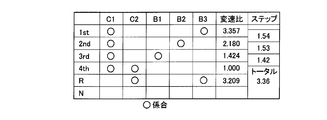
- FIG. 2 is an operation chart for explaining a relationship between a shift operation of an automatic transmission unit provided in the vehicle drive device of FIG. 1 and a combination of operations of a hydraulic friction engagement device used therefor.
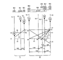
- FIG. 2 is a collinear diagram illustrating a relative rotational speed of each gear stage in the vehicle drive device of FIG. 1. It is a figure explaining the input-output signal of the electronic controller provided in the vehicle drive device of FIG. It is an example of the shift operation apparatus operated in order to select multiple types of shift positions provided with the shift lever for performing gear shifting operation of the vehicle drive device of FIG. It is a functional block diagram explaining the principal part of the control function by the electronic controller of FIG.
- FIG. 5 is a flowchart for explaining a main part of a control operation of the electronic control device of FIG. 4, that is, a control operation for executing input torque limit control. It is a flowchart for demonstrating the principal part of the control action in step SA3 of FIG.
- the input torque limit control when the accelerator pedal is depressed slowly is taken as an example in the case where a power-on downshift from the second speed to the first speed of the automatic transmission is performed while the engine is running. It is a time chart for explaining.
- the input torque limiting control at the time when the accelerator pedal is quickly depressed is taken as an example in the case where a power-on downshift from the second speed to the first speed of the automatic transmission is performed during engine running. It is a time chart for explaining. It is a time chart for demonstrating that the acceleration shock of 2 steps
- FIG. 1 is a skeleton diagram illustrating a main part of a vehicle drive device 7 constituting a vehicle 6 (see FIG. 6) to which the present invention is applied.
- a vehicle drive device 7 (hereinafter referred to as “drive device 7”) includes an engine 8 that is an internal combustion engine such as a gasoline engine or a diesel engine, and a power transmission device 10 as a driving power source for traveling.
- the engine 8 is directly connected to the input shaft 14 of the power transmission device 10 or directly via a pulsation absorbing damper (not shown).
- the power transmission device 10 includes an input shaft 14 disposed on a common axis in a transmission case 12 (hereinafter referred to as “case 12”) as a non-rotating member attached to a vehicle body, and the input shaft 14 directly.
- a differential unit 11 as a continuously variable transmission unit indirectly connected via a pulsation absorbing damper (vibration damping device) or the like (not shown), and between the differential unit 11 and the drive wheel 34 (see FIG. 6).
- An automatic transmission unit 20 as a mechanical power transmission unit connected in series via a transmission member (transmission shaft) 18 in the power transmission path of the motor, and an output as an output rotation member connected to the automatic transmission unit 20
- a shaft 22 is provided in series.
- the power transmission device 10 is preferably used for, for example, an FR (front engine / rear drive) type hybrid vehicle installed vertically in a vehicle, and is provided between the engine 8 and a pair of drive wheels 34. Then, the power from the engine 8 is transmitted to the pair of drive wheels 34 through the differential gear device (final reduction gear) 32 (see FIG. 6) and a pair of axles which constitute a part of the power transmission path.
- FR front engine / rear drive
- the engine 8 and the differential unit 11 are directly connected.
- This direct connection means that the connection is made without using a hydraulic power transmission device such as a torque converter or a fluid coupling.
- the connection via the pulsation absorbing damper is included in this direct connection.
- the engine 8 and the differential unit 11 having the first electric motor M ⁇ b> 1 and the second electric motor M ⁇ b> 2 constitute a power source 36 that supplies torque to the automatic transmission unit 20. That is, the engine 8, the first electric motor M1, and the second electric motor M2 are all provided so as to be able to transmit power to the transmission member 18 that is an input rotation member of the automatic transmission unit 20. Since the power transmission device 10 is configured symmetrically with respect to its axis, the lower side is omitted in the skeleton diagram of FIG.
- the differential unit 11 is a mechanical mechanism that mechanically distributes the output of the engine 8 input to the input shaft 14, and serves as a differential mechanism that distributes the output of the engine 8 to the first electric motor M ⁇ b> 1 and the transmission member 18.
- a power distribution mechanism 16 a first electric motor M1 connected to the power distribution mechanism 16 so as to be able to transmit power, and a second electric motor M2 operatively connected to rotate integrally with the transmission member 18.
- the first motor M1 and the second motor M2 of the present embodiment are so-called motor generators that also have a power generation function, but the first motor M1 that functions as a differential motor for controlling the differential state of the power distribution mechanism 16. Includes at least a generator (power generation) function for generating a reaction force.
- the second electric motor M2 connected to the drive wheel 34 so as to be able to transmit power is provided with at least a motor (electric motor) function in order to function as a traveling motor that outputs a driving force as a driving force source for traveling.
- the first electric motor M1 and the second electric motor M2 correspond to one or more electric motors of the present invention.
- the engine 8, the first electric motor M ⁇ b> 1, and the transmission member 18 are connected to different rotating elements RE ⁇ b> 1, RE ⁇ b> 2, and RE ⁇ b> 3 included in the power distribution mechanism 16, respectively, so It is the differential mechanism provided in.
- the power distribution mechanism 16 is mainly composed of a single pinion type differential unit planetary gear unit 24.
- the differential unit planetary gear device 24 has a predetermined gear ratio ⁇ 0 of about “0.418”, for example, and rotates the differential unit sun gear S0, the differential unit planetary gear P0, and the differential unit planetary gear P0.
- a differential part carrier CA0 that is supported so as to be able to revolve, and a differential part ring gear R0 that meshes with the differential part sun gear S0 via a differential part planetary gear P0 are provided as rotating elements (elements). If the number of teeth of the differential sun gear S0 is ZS0 and the number of teeth of the differential ring gear R0 is ZR0, the gear ratio ⁇ 0 is ZS0 / ZR0.
- the differential carrier CA0 is connected to the input shaft 14, that is, the engine 8, the differential sun gear S0 is connected to the first electric motor M1, and the differential ring gear R0 is connected to the transmission member 18. ing.
- the differential unit sun gear S0, the differential unit carrier CA0, and the differential unit ring gear R0 which are the three elements of the differential unit planetary gear unit 24, can be rotated relative to each other.
- the differential action is operable, that is, the differential state where the differential action works is set, so that the output of the engine 8 is distributed to the first electric motor M1 and the transmission member 18, and the output of the distributed engine 8 is distributed.
- the differential unit 11 (power distribution mechanism 16) functions as an electric differential device.
- the differential section 11 is in a so-called continuously variable transmission state (electric CVT state), and the rotation of the transmission member 18 is continuously changed regardless of the predetermined rotation of the engine 8. That is, the differential unit 11 is an electrically stepless variable gear whose ratio ⁇ 0 (the rotational speed N IN of the input shaft 14 / the rotational speed N 18 of the transmission member 18 ) is continuously changed from the minimum value ⁇ 0min to the maximum value ⁇ 0max. It functions as a transmission.
- the differential state of the power distribution mechanism 16 that is, the input shaft 14 is controlled by controlling the operation state of the first electric motor M1 and / or the second electric motor M2 connected to the power distribution mechanism 16 so as to be able to transmit power.
- the differential state between the rotational speed of the transmission member and the rotational speed of the transmission member 18 is controlled.
- the automatic transmission unit 20 constitutes a part of a power transmission path from the power source 36 to the drive wheel 34, and includes a single pinion type first planetary gear unit 26, a single pinion type second planetary gear unit 28, and This is a planetary gear type multi-stage transmission that includes a single pinion type third planetary gear device 30 and functions as a stepped automatic transmission.
- the first planetary gear unit 26 includes a first sun gear S1, a first planetary gear P1, a first carrier CA1 that supports the first planetary gear P1 so as to rotate and revolve, and a first sun gear S1 via the first planetary gear P1.
- the first ring gear R1 meshing with the first gear R1 has a predetermined gear ratio ⁇ 1 of about “0.562”, for example.
- the second planetary gear device 28 includes a second sun gear S2 via a second sun gear S2, a second planetary gear P2, a second carrier CA2 that supports the second planetary gear P2 so as to rotate and revolve, and a second planetary gear P2.
- the second ring gear R2 that meshes with the second gear R2 has a predetermined gear ratio ⁇ 2 of about “0.425”, for example.
- the third planetary gear device 30 includes a third sun gear S3, a third planetary gear P3, a third carrier CA3 that supports the third planetary gear P3 so as to rotate and revolve, and a third sun gear S3 via the third planetary gear P3.
- a third ring gear R3 that meshes with the gear, and has a predetermined gear ratio ⁇ 3 of about “0.421”, for example.
- the number of teeth of the first sun gear S1 is ZS1
- the number of teeth of the first ring gear R1 is ZR1
- the number of teeth of the second sun gear S2 is ZS2
- the number of teeth of the second ring gear R2 is ZR2
- the number of teeth of the third sun gear S3 is ZS3
- the gear ratio ⁇ 1 is ZS1 / ZR1
- the gear ratio ⁇ 2 is ZS2 / ZR2
- the gear ratio ⁇ 3 is ZS3 / ZR3.
- the first sun gear S1 and the second sun gear S2 are integrally connected and selectively connected to the transmission member 18 via the second clutch C2 and the case 12 via the first brake B1.
- the first carrier CA1 is selectively connected to the case 12 via the second brake B2
- the third ring gear R3 is selectively connected to the case 12 via the third brake B3,
- the first ring gear R1, the second carrier CA2, and the third carrier CA3 are integrally connected to the output shaft 22, and the second ring gear R2 and the third sun gear S3 are integrally connected to connect the first clutch C1. And selectively connected to the transmission member 18.
- the automatic transmission unit 20 and the differential unit 11 are selectively connected via the first clutch C1 or the second clutch C2 used to establish the gear position of the automatic transmission unit 20. It is connected.
- the first clutch C1 and the second clutch C2 have a power transmission path between the transmission member 18 and the automatic transmission unit 20, that is, a power transmission path from the differential unit 11 (transmission member 18) to the drive wheels 34. It functions as an engagement device that selectively switches between a power transmission enabling state that enables power transmission on the power transmission path and a power transmission cutoff state that interrupts power transmission on the power transmission path.
- the power transmission path is brought into a power transmission enabled state, or the first clutch C1 and the second clutch C2 are released.
- the power transmission path is brought into a power transmission cutoff state.
- the automatic transmission unit 20 performs clutch-to-clutch shift by releasing the disengagement side engagement device and engaging the engagement side engagement device, and selectively establishes each gear stage (shift stage).
- the first speed gear stage in which the gear ratio ⁇ 1 is the maximum value, for example, “3.357” is established by the engagement of the first clutch C1 and the third brake B3.
- the engagement of the first clutch C1 and the second brake B2 establishes the second speed gear stage in which the speed ratio ⁇ 2 is smaller than the first speed gear stage, for example, about “2.180”.
- the engagement of the clutch C1 and the first brake B1 establishes the third speed gear stage in which the speed ratio ⁇ 3 is smaller than the second speed gear stage, for example, about “1.424”.
- Engagement of the clutch C2 establishes the fourth speed gear stage in which the speed ratio ⁇ 4 is smaller than the third speed gear stage, for example, about “1.000”.
- the reverse gear stage in which the speed ratio ⁇ R is a value between the first speed gear stage and the second speed gear stage, for example, about “3.209”. Stage
- the neutral "N" state is established by releasing the first clutch C1, the second clutch C2, the first brake B1, the second brake B2, and the third brake B3.
- the first clutch C1, the second clutch C2, the first brake B1, the second brake B2, and the third brake B3 are conventional automatic transmissions for vehicles.
- a hydraulic friction engagement device as an engagement element often used in a machine, and a wet multi-plate type in which a plurality of friction plates stacked on each other are pressed by a hydraulic actuator, or an outer peripheral surface of a rotating drum
- One end of one or two bands wound around is composed of a band brake or the like that is tightened by a hydraulic actuator, and is for selectively connecting the members on both sides of the band brake.
- the differential unit 11 that functions as a continuously variable transmission and the automatic transmission unit 20 constitute a continuously variable transmission as a whole. Further, by controlling the gear ratio of the differential unit 11 to be constant, the differential unit 11 and the automatic transmission unit 20 can configure a state equivalent to a stepped transmission.
- the differential unit 11 functions as a continuously variable transmission
- the automatic transmission unit 20 in series with the differential unit 11 functions as a stepped transmission, whereby at least one shift of the automatic transmission unit 20 is performed.
- the rotational speed input to the automatic transmission unit 20 with respect to the stage M that is, the rotational speed N 18 of the transmission member 18 (hereinafter referred to as “transmission member rotational speed N 18 ”) is changed steplessly and the gear stage is changed.
- the overall speed ratio ⁇ T of the power transmission device 10 is a total speed ratio ⁇ T of the power transmission device 10 as a whole formed based on the speed ratio ⁇ 0 of the differential unit 11 and the speed ratio ⁇ of the automatic transmission unit 20.
- first gear or transmission member rotational speed N 18 is continuously variable varying for each gear of the fourth gear and the reverse gear position of the automatic transmission portion 20 indicated in the table of FIG. 2
- each gear stage has a continuously variable transmission ratio width. Therefore, the gear ratio between the gear stages can be continuously changed continuously, and the total gear ratio ⁇ T of the power transmission device 10 as a whole can be obtained continuously.
- the gear ratio of the differential unit 11 is controlled to be constant, and the clutch C and the brake B are selectively engaged and operated, so that one of the first gear to the fourth gear or the reverse drive
- a total gear ratio ⁇ T of the power transmission device 10 that changes in a substantially equal ratio is obtained for each gear stage. Therefore, a state equivalent to the stepped transmission is configured in the power transmission device 10.
- the gear ratio ⁇ 0 of the differential unit 11 when the gear ratio ⁇ 0 of the differential unit 11 is controlled to be fixed to “1”, the first to fourth gear stages of the automatic transmission unit 20 as shown in the engagement operation table of FIG. A total gear ratio ⁇ T of the power transmission device 10 corresponding to each gear stage such as a high speed gear stage and a reverse gear stage is obtained for each gear stage. Further, if the gear ratio ⁇ 0 of the differential unit 11 is controlled to be fixed to a value smaller than “1”, for example, about 0.7 in the fourth speed gear stage of the automatic transmission unit 20, the fourth speed gear stage Is obtained, for example, a total speed ratio ⁇ T of about “0.7”.
- FIG. 3 shows a linear relationship between the rotational speeds of the rotating elements having different connection states for each gear stage in the power transmission device 10 including the differential unit 11 and the automatic transmission unit 20.
- a diagram is shown.
- the collinear diagram of FIG. 3 is a two-dimensional coordinate composed of a horizontal axis indicating the relationship of the gear ratio ⁇ of each planetary gear unit 24, 26, 28, 30 and a vertical axis indicating the relative rotational speed.
- X1 represents a rotational speed zero, represents the rotational speed N E of the engine 8
- horizontal line X2 is linked to the rotational speed of "1.0", that is the input shaft 14, horizontal line XG indicates the rotational speed of the power transmitting member 18.
- three vertical lines Y1, Y2, and Y3 corresponding to the three elements of the power distribution mechanism 16 constituting the differential unit 11 indicate the differential corresponding to the second rotation element (second element) RE2 in order from the left side.
- These intervals are determined according to the gear ratio ⁇ 0 of the differential planetary gear unit 24.
- the five vertical lines Y4, Y5, Y6, Y7, Y8 of the automatic transmission unit 20 correspond to the fourth rotation element (fourth element) RE4 and are connected to each other in order from the left.
- the second sun gear S2 the first carrier CA1 corresponding to the fifth rotation element (fifth element) RE5, the third ring gear R3 corresponding to the sixth rotation element (sixth element) RE6, the seventh rotation element ( Seventh element)
- the first ring gear R1, the second carrier CA2, and the third carrier CA3 corresponding to RE7 and connected to each other are connected to the eighth rotation element (eighth element) RE8 and connected to each other.
- the two ring gear R2 and the third sun gear S3 are respectively represented, and the distance between them is determined according to the gear ratios ⁇ 1, ⁇ 2, and ⁇ 3 of the first, second, and third planetary gear devices 26, 28, and 30, respectively.
- the interval between the carrier and the ring gear is set to an interval corresponding to the gear ratio ⁇ of the planetary gear device. That is, in the differential section 11, the interval between the vertical lines Y1 and Y2 is set to an interval corresponding to “1”, and the interval between the vertical lines Y2 and Y3 is set to an interval corresponding to the gear ratio ⁇ 0.
- the space between the sun gear and the carrier is set at an interval corresponding to "1" for each of the first, second, and third planetary gear devices 26, 28, and 30, so that the carrier and the ring gear
- the interval is set to an interval corresponding to ⁇ .
- the power transmission device 10 of the present embodiment is configured so that the power distribution mechanism 16 (differential unit 11) has the first rotating element RE1 (The differential carrier CA0) is connected to the input shaft 14, that is, the engine 8, the second rotating element RE2 is connected to the first electric motor M1, and the third rotating element (differential ring gear R0) RE3 is connected to the transmission member 18 and the second rotating element RE2. It is connected to the electric motor M2, and is configured to transmit (input) the rotation of the input shaft 14 to the automatic transmission unit 20 via the transmission member 18.
- the relationship between the rotational speed of the differential section sun gear S0 and the rotational speed of the differential section ring gear R0 is shown by an oblique straight line L0 passing through the intersection of Y2 and X2.
- the first rotation element RE1 to the third rotation element RE3 are in a differential state in which they can rotate relative to each other, and the difference indicated by the intersection of the straight line L0 and the vertical line Y3.
- rotational speed of the dynamic portion ring gear R0 is bound with the vehicle speed V in the case of substantially constant, the differential portion carrier CA0, represented by an intersecting point between the straight line L0 and the vertical line Y2 by controlling the engine rotational speed N E
- the rotation speed of the differential sun gear S0 indicated by the intersection of the straight line L0 and the vertical line Y1 that is, the rotation speed of the first electric motor M1 is increased or decreased.
- the rotation of the differential portion sun gear S0 is the same speed as the engine speed N E by controlling the rotational speed of the first electric motor M1 such speed ratio ⁇ 0 of the differential portion 11 is fixed to "1" If that, the straight line L0 is aligned with the horizontal line X2, the rotational speed, i.e., the power transmitting member 18 of the differential portion ring gear R0 at a speed equal to the engine speed N E is rotated. Alternatively, by controlling the rotational speed of the first electric motor M1 so that the speed ratio ⁇ 0 of the differential section 11 is fixed to a value smaller than “1”, for example, about 0.7, the rotation of the differential section sun gear S0 becomes zero. Once, the transmitting member rotational speed N 18 is rotated at a rotation speed higher than the engine speed N E.
- the fourth rotation element RE4 is selectively connected to the transmission member 18 via the second clutch C2, and is also selectively connected to the case 12 via the first brake B1, for the fifth rotation.
- the element RE5 is selectively connected to the case 12 via the second brake B2
- the sixth rotating element RE6 is selectively connected to the case 12 via the third brake B3, and the seventh rotating element RE7 is connected to the output shaft 22.
- the eighth rotary element RE8 is selectively connected to the transmission member 18 via the first clutch C1.
- FIG. 4 illustrates a signal input to the electronic control device 80 and a signal output from the electronic control device 80 according to the present embodiment.
- the electronic control unit 80 has a function as a control unit for controlling the drive unit 7 and includes a so-called microcomputer including a CPU, a ROM, a RAM, an input / output interface, and the like.
- a microcomputer including a CPU, a ROM, a RAM, an input / output interface, and the like.
- drive control such as hybrid drive control for the engine 8, the first and second electric motors M1 and M2, and the shift control of the automatic transmission unit 20 is performed. It is something to execute.
- the electronic control unit 80 receives signals indicating the engine water temperature TEMP W from the sensors and switches as shown in FIG. 4, the number of operations at the shift position P SH of the shift lever 52 (see FIG. 5), the “M” position, and the like.
- a signal representing a gear ratio row set value a signal for instructing an M mode (manual shift running mode), a signal representing an operation of an air conditioner, and a rotational speed of the output shaft 22 (hereinafter, output shaft rotational speed) N OUT signal representing the vehicle speed V
- the signal representing the hydraulic oil temperature TEMP ATF of the automatic shifting portion 20 a signal indicative of a side brake operation, a signal indicative of a foot brake operation, a signal indicative of the catalyst temperature
- Signal representing setting signal representing longitudinal acceleration G of vehicle, signal representing auto cruise traveling, signal representing vehicle weight (vehicle weight), signal representing wheel speed of each wheel, rotational speed N M1 of first electric motor M1 (Hereinafter, referred to as “first motor
- the hydraulic control circuit 70 signal for applying regulates the line pressure P L by a regulator valve (pressure regulating valve) provided in the drive for operating an electric hydraulic pump serving as a hydraulic pressure source of the original pressure for the line pressure P L is pressure adjusted
- a command signal, a signal for driving the electric heater, a signal to the cruise control computer, etc. are output respectively. .
- FIG. 5 is a diagram showing an example of a shift operation device 50 as a switching device for switching a plurality of types of shift positions PSH by an artificial operation.
- the shift operation device 50 includes, for example, a shift lever 52 that is disposed beside the driver's seat and is operated to select a plurality of types of shift positions PSH .
- the shift lever 52 is placed in a neutral state, that is, a neutral state in which the power transmission path in the power transmission device 10, that is, the automatic transmission unit 20 is interrupted, and is a parking position “P (” for locking the output shaft 22 of the automatic transmission unit 20. Parking) ”, reverse travel position“ R (reverse) ”for reverse travel, neutral position“ N (neutral) ”for neutral state where power transmission path in power transmission device 10 is cut off, automatic transmission mode Is established, and the power transmission obtained by the continuously variable transmission ratio width of the differential unit 11 and each gear stage that is automatically controlled to shift within the range of the first to fourth gear stages of the automatic transmission unit 20.
- the forward automatic shift travel position “D (drive)” for executing automatic shift control within the change range of the total speed change ratio ⁇ T of the device 10 or the manual shift travel mode. (Manual mode) is established and is provided so as to be manually operated to a forward manual shift travel position “M (manual)” for setting a so-called shift range for limiting the high-speed shift stage in the automatic transmission unit 20. Yes.
- the “P” position and the “N” position are non-traveling positions that are selected when the vehicle is not traveling.
- the first clutch C1 that disables driving of the vehicle in which the power transmission path in the automatic transmission unit 20 in which both the first clutch C1 and the second clutch C2 are released is interrupted. This is a non-driving position for selecting switching to the power transmission cutoff state of the power transmission path by the second clutch C2.
- the “R” position, the “D” position, and the “M” position are travel positions that are selected when the vehicle travels. For example, as shown in the engagement operation table of FIG.
- a power transmission path by the first clutch C1 and / or the second clutch C2 capable of driving a vehicle to which a power transmission path in the automatic transmission 20 is engaged so that at least one of the second clutch C2 is engaged. It is also a drive position for selecting switching to a power transmission enabled state.
- FIG. 6 is a functional block diagram for explaining the main part of the control function by the electronic control unit 80.
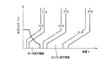
- the stepped shift control means 82 includes an upshift line (solid line) and a downshift line (one point) stored in advance with the vehicle speed V and the output torque T OUT of the automatic transmission unit 20 as shown in FIG. Whether or not the shift of the automatic transmission unit 20 should be executed based on the vehicle state indicated by the actual vehicle speed V and the required output torque T OUT of the automatic transmission unit 20 from the relationship (chain diagram, shift map) having a chain line) That is, that is, the shift stage to be shifted by the automatic transmission unit 20 is determined, and the automatic shift control of the automatic transmission unit 20 is executed so that the determined shift stage is obtained.
- the stepped shift control means 82 engages and / or engages the hydraulic friction engagement device involved in the shift of the automatic transmission unit 20 so that the shift stage is achieved, for example, according to the engagement table shown in FIG.
- a clutch-to-clutch shift is executed by releasing a release command (shift output command, hydraulic pressure command), that is, by releasing the release-side engagement device involved in the shift of the automatic transmission unit 20 and engaging the engagement-side engagement device.
- Command to output to the hydraulic control circuit 70 In accordance with the command, for example, the hydraulic control circuit 70 releases the disengagement side engagement device and engages the engagement side engagement device so that the shift of the automatic transmission unit 20 is executed.
- a linear solenoid valve is actuated to actuate a hydraulic actuator of a hydraulic friction engagement device that is involved in the speed change.
- the hybrid control means 84 operates the engine 8 in an efficient operating range, while changing the driving force distribution between the engine 8 and the second electric motor M2 and the reaction force generated by the first electric motor M1 to be optimized.
- the gear ratio ⁇ 0 of the differential unit 11 as an electric continuously variable transmission is controlled.
- the target (request) output of the vehicle is calculated from the accelerator opening Acc and the vehicle speed V as the driver's required output amount, and the total required from the target output and the required charging value of the vehicle.
- Calculate the target output calculate the target engine output in consideration of transmission loss, auxiliary load, assist torque of the second motor M2, etc. so as to obtain the total target output, and obtain the target engine output. so that the speed N E and engine torque T E to control the amount of power generated by the first electric motor M1 controls the engine 8.
- the hybrid control means 84 executes the control in consideration of the gear position of the automatic transmission unit 20 for improving power performance and fuel consumption.
- the differential unit 11 is caused to function as an electric continuously variable transmission.
- the hybrid control means 84 to achieve both the drivability and the fuel consumption when the continuously-variable shifting control in a two-dimensional coordinate composed of the output torque (engine torque) T E of the engine rotational speed N E and the engine 8
- an optimum fuel consumption rate curve fuel consumption map, relationship
- the operating point of the engine 8 hereinafter, “ as the engine 8 while indicating an engine operating point ”
- the target output total target output, the engine torque T E for generating the engine output necessary to meet the required driving force
- the engine rotational speed N E determines the target value of the overall speed ratio ⁇ T of the power transmission device 10
- the shift of the automatic shifting portion 20 so as to obtain the target value
- the taking into account by controlling the speed ratio ⁇ 0 of the differential portion 11 is controlled in its variable speed change range overall speed ratio [gamma] T.
- the above-mentioned engine operating point, indicating the operating state of the engine rotational speed N E and the engine 8 in a two-dimensional coordinates with coordinate axes state quantity indicating the operating state of the engine 8 is exemplified by such engine torque T E operation Is a point.
- the fuel consumption is a travel distance per unit fuel consumption
- the improvement in fuel consumption is an increase in the travel distance per unit fuel consumption, or as a whole vehicle.
- a reduction in fuel consumption means that the travel distance per unit fuel consumption is shortened, or the fuel consumption rate of the entire vehicle is increased.
- the hybrid control means 84 supplies the electric energy generated by the first electric motor M1 to the power storage device 56 and the second electric motor M2 through the inverter 54, so that the main part of the power of the engine 8 is mechanically transmitted to the transmission member 18.
- a part of the motive power of the engine 8 is consumed for power generation of the first electric motor M1 and converted into electric energy there, and the electric energy is supplied to the second electric motor M2 through the inverter 54,
- the second electric motor M2 is driven and transmitted from the second electric motor M2 to the transmission member 18.
- the power storage device 56 supplies electric power to each of the first electric motor M1 and the second electric motor M2, that is, supplies electric power to the electric motors M1 and M2, and supplies electric power from the electric motors M1 and M2.
- An electric energy source capable of receiving the battery for example, a battery such as a lead storage battery or a capacitor.
- the hybrid control means 84 controls the first motor rotation speed N M1 and / or the second motor rotation speed N M2 by the electric CVT function of the differential section 11 regardless of whether the vehicle is stopped or traveling. It controls the rotation of the engine rotational speed N E to any rotational speed or maintained substantially constant. In other words, the hybrid control means 84, rotating the first electric motor speed N M1 and / or the second electric motor rotation speed N M2 while controlling any rotational speed or to maintain the engine speed N E substantially constant for any The rotation can be controlled to the speed.
- the hybrid control means 84 as can be seen from the diagram of FIG. 3 when raising the engine rotation speed N E during running of the vehicle, the vehicle speed V the second electric motor rotation speed N which is bound to the (drive wheels 34)
- the first motor rotation speed N M1 is increased while maintaining M2 substantially constant.
- the hybrid control means 84 when maintaining the engine speed N E at the nearly fixed level during the shifting of the automatic shifting portion 20, due to the shift of the automatic transmission portion 20 while maintaining the engine speed N E substantially constant
- the first motor rotation speed N M1 is changed in the direction opposite to the change of the second motor rotation speed N M2 .
- the hybrid control means 84 controls the opening and closing of the electronic throttle valve 62 by the throttle actuator 64 for the throttle control, and controls the fuel injection amount and the injection timing by the fuel injection device 66 for the fuel injection control.
- a command for controlling the ignition timing by the ignition device 68 such as an igniter is output to the engine output control device 58 alone or in combination, and the output control of the engine 8 is executed so as to generate the necessary engine output.
- An engine output control means is functionally provided.
- the hybrid controller 84 basically drives the throttle actuator 64 based on the accelerator opening Acc from a previously stored relationship (not shown), and increases the throttle valve opening ⁇ TH as the accelerator opening Acc increases. Throttle control is executed so that Further, the engine output control device 58 controls the opening and closing of the electronic throttle valve 62 by the throttle actuator 64 for throttle control according to the command from the hybrid control means 84, and the fuel injection by the fuel injection device 66 for fuel injection control.
- the engine torque control is executed by controlling the ignition timing by an ignition device 68 such as an igniter for controlling the ignition timing.
- the hybrid control means 84 uses the electric CVT function (differential action) of the differential unit 11 to drive the motor using the second electric motor M2 as a driving force source for driving regardless of whether the engine 8 is stopped or in an idle state. Can be made.
- the hybrid control means 84 typically a relatively low output torque T OUT region or low engine torque T E region the engine efficiency is poor compared to the high torque region, or a relatively low vehicle speed range of the vehicle speed V That is, the motor travel is executed in the low load region.
- the hybrid control means 84 controls the first motor rotation speed N M1 at a negative rotation speed in order to suppress the drag of the stopped engine 8 and improve fuel consumption during the motor running, for example, the first electric motor M1 is rotated in idle and by a no-load state, to maintain the engine speed N E at zero or substantially zero as needed by the electric CVT function of the differential portion 11 (differential action).
- the hybrid control unit 84 is configured to use the electric energy from the first electric motor M1 and / or the power storage device 56 by the above-described electric path even in an engine traveling region in which the engine 8 travels using the engine 8 as a driving power source. Is supplied to the second electric motor M2, and the second electric motor M2 is driven to apply torque to the drive wheels 34, so that so-called torque assist for assisting the power of the engine 8 is possible. Therefore, in the engine running of the present embodiment, there are a case where the engine 8 is used as a driving power source for driving and a case where both the engine 8 and the second electric motor M2 are used as driving power sources for driving.
- the motor travel of the present embodiment is travel that stops the engine 8 and uses the second electric motor M2 as a drive power source for travel.
- the hybrid control means 84 makes the first electric motor M1 in a no-load state and freely rotates, that is, idles, so that the differential unit 11 cannot transmit torque, that is, the power transmission path in the differential unit 11 is interrupted. It is possible to make the state equivalent to the state in which the output from the differential unit 11 is not generated. That is, the hybrid control means 84 can place the differential motor 11 in a neutral state (neutral state) in which the power transmission path is electrically cut off by setting the first electric motor M1 to a no-load state.
- the hybrid control means 84 is transmitted from the kinetic energy of the vehicle, that is, from the drive wheels 34 to the engine 8 side in order to improve fuel efficiency, for example, when coasting with the accelerator off (during coasting) or braking with a foot brake.
- the second electric motor M2 is rotationally driven by the reverse driving force to act as a generator, and the electric energy, that is, the second electric motor generated current is charged to the power storage device 56 via the inverter 54 as a regeneration control means.
- the regenerative control is performed so that the regenerative amount is determined based on the braking force distribution of the braking force by the hydraulic brake for obtaining the braking force according to the remaining charge SOC of the power storage device 56 and the brake pedal operation amount. Is done.
- the electronic control unit 80 includes the stepped shift control unit 82 and the hybrid control unit 84 that perform the control as described above, but the power-on that is a downshift of the automatic transmission unit 20 performed during the accelerator stepping operation.
- the electronic control unit 80 further includes power-on downshift determining means 88, inertia phase start determining means 90, accelerator change determining means 92, and input torque limit control means 94. Yes.
- the power-on downshift determining means 88 determines whether or not a downshift of the automatic transmission unit 20 is performed during the accelerator depression operation, that is, whether or not a power-on downshift is performed. For example, when the accelerator pedal 46 is depressed and the accelerator opening Acc, which is the amount of accelerator operation, is not zero, the power-on downshift determining means 88 determines that the accelerator operation is being performed, and the accelerator During the stepping operation, when the stepped shift control means 82 makes a shift determination to execute the downshift of the automatic transmission unit 20 based on the vehicle state from the shift diagram (see FIG. 7), the power It is determined that an on-down shift is performed. The power-on downshift determining means 88 performs this power-on downshift until the stepped shift control means 82 outputs a shift output commanding the hydraulic control circuit 70 to execute the downshift based on the shift determination. Judgment is made or not.
- the inertia phase start determining means 90 determines whether or not the downshift inertia phase has started in the downshift of the automatic transmission unit 20 started by the shift output. It is whether the inertia phase has started, for example, can be detected from the rotational speed N M2 of the second electric motor M2 connected to the power transmitting member 18 which is the input rotary member of the automatic shifting portion 20. When the inertia phase has not started, the inertia phase start determination means 90 determines that the inertia phase has not started yet.
- the accelerator change determining means 92 determines whether or not the change in the accelerator opening Acc, that is, the accelerator change VR ACC is equal to or less than a predetermined accelerator change limit L1 ACC .
- the accelerator change determination means 92 makes this determination on the accelerator change VR ACC before the start of the downshift, for example, the accelerator change VR ACC before the shift output.
- a case where the accelerator change VR ACC is less than or equal to the accelerator change limit L1 ACC is referred to as a slow depression of the accelerator pedal 46, and a case where the accelerator change VR ACC is greater than the accelerator change limit L1 ACC is referred to as an early depression of the accelerator pedal 46.
- an accelerator opening Acc is the accelerator operation amount is that of the accelerator operating speed SA CC is a substantial increase in per unit of the accelerator operation amount Acc time, either May be applicable. Therefore, if the accelerator change VR ACC is the accelerator operation amount Acc, the accelerator change determining means 92 has the accelerator operation amount Acc equal to or less than a predetermined accelerator operation amount determination value LQ ACC corresponding to the accelerator change limit L1 ACC. If the accelerator operation amount Acc is less than or equal to the accelerator operation amount determination value LQ ACC, it is determined that the accelerator change VR ACC is less than or equal to the accelerator change limit L1 ACC .
- the accelerator variation VR ACC is the accelerator operating speed SA CC, accelerator change determination means 92, the accelerator operating speed SA CC is, the accelerator variation limit L1 predetermined accelerator operation speed determination value corresponding to the ACC LS ACC If the accelerator operation speed SACC is not more than the accelerator operation speed determination value LS ACC, it is determined that the accelerator change VR ACC is not more than the accelerator change limit L1 ACC .
- the accelerator operation amount determination value LQ ACC is a determination value set for the accelerator operation amount Acc and stored in the accelerator change determination means 92. If the accelerator operation amount Acc is less than that, the engine torque TE is the accelerator pedal. It is an experimentally predetermined determination value that can be determined to follow up without substantially delaying the operation.
- the accelerator operation speed determination value LS ACC is a determination value set for the accelerator operation speed SA CC and stored in the accelerator change determination means 92. If the accelerator operation speed SA CC is less than that, the engine torque T E is an experimentally predetermined determination value that can determine that E has risen following the accelerator pedal operation without substantial delay.
- the accelerator variation determining means 92 there is no obstacle to the free determination for both the accelerator operation amount Acc and the accelerator operating speed SA CC is the accelerator variation VR ACC.
- the accelerator change determination means 92 is such that the accelerator operation amount Acc is less than or equal to the accelerator operation amount determination value LQ ACC and the accelerator operation speed SACC is less than or equal to the accelerator operation speed determination value LS ACC .
- the accelerator change determination unit 92 based on such output torque T OUT of the automatic shifting portion 20 (the output torque T OUT of the driving device 7), it is determined whether the slow stepping or rapid depression of the accelerator pedal 46 There is no problem. Since the output torque T OUT of the automatic transmission portion 20 is changed in accordance with the engine torque T E, followability to the accelerator pedal operation of the output torque T OUT of the automatic shifting portion 20, when the slow depression of the accelerator pedal 46 Is good, but there is a correlation that it becomes worse when the accelerator pedal 46 is quickly depressed.
- the accelerator change determining unit 92 determines the output torque T OUT of the automatic transmission unit 20 as a parameter.
- the accelerator change determining unit 92 includes the stepped shift control unit 82 that executes the downshift. It is determined whether or not the output torque T OUT of the automatic transmission unit 20 at the commanded shift output is greater than or equal to a predetermined output torque determination value LT OUT . As a result, when the output torque T OUT of the automatic transmission unit 20 at the time of the shift output is equal to or greater than the output torque determination value LT OUT , the accelerator change determining unit 92 determines that the accelerator change VR ACC before the start of the downshift is It is determined that the acceleration change limit L1 ACC or less.
- the accelerator change determination unit 92 determines the accelerator change VR ACC before the start of the downshift. Is determined to be greater than the accelerator change limit L1 ACC . From this, it can be said that the accelerator change determining means 92 for determining the output torque T OUT of the automatic transmission unit 20 functions as an output torque determining means.
- the output torque T OUT of the automatic transmission unit 20 is, for example, the output torque T M1 of the first electric motor M1 determined according to the control current value of the first electric motor M1 (hereinafter referred to as “first electric motor torque T M1 ”).
- the output torque T M2 (hereinafter referred to as “second motor torque T M2 ”) determined according to the control current value of the second motor M2, the current gear position of the automatic transmission unit 20, and the like. It can be calculated.
- the output torque determination value LT OUT is a determination value stored in the accelerator change determination unit 92. If the output torque T OUT of the automatic transmission unit 20 at the time of the shift output is higher than that, the output torque T OUT is determined. Is an experimentally determined determination value that can be determined to follow the accelerator pedal operation without substantially delaying.
- the output torque determination value LT OUT is changed according to the accelerator opening Acc at the time of the shift output, the gear position of the automatic transmission unit 20 before being downshifted by the shift output, and the like.
- the output torque determination value LT OUT is increased as the accelerator opening Acc at the time of the shift output is increased, and is decreased as the shift stage of the automatic transmission unit 20 before downshifting is higher. .
- the accelerator change determination unit 92 determines the output torque T OUT of the automatic transmission unit 20 at the time of the shift output.
- the accelerator change determination unit 92 considers the processing time for the determination, and at the time of the shift output.
- the above determination may be made by regarding the output torque T OUT of the automatic transmission unit 20 before a predetermined minute time as being at the time of the shift output. Since the shift determination is made before the shift output, it can be predicted from the shift determination.
- the input torque limit control unit 94 returns to the automatic transmission unit 20 before the start of the downshift inertia phase of the automatic transmission unit 20.
- the input torque T ATIN (hereinafter referred to as “AT input torque T ATIN ”) is compared with a case where the downshift is not performed, and input torque limit control is executed.
- the case where the downshift is not performed is, for example, a case where the shift of the automatic transmission unit 20 is not performed, or a case where the upshift of the automatic transmission unit 20 is performed.
- the input torque limit control means 94 limits the AT input torque TATIN while the inertia phase start determination means 90 determines that the inertia phase of the downshift is not yet started in the input torque limit control. To do.
- the input torque limit control means 94 executes the input torque limit control when, for example, the power-on downshift is performed while the engine is running.
- AT input torque T ATIN is either may limit be restricted to the engine torque T E and the second electric motor M2 torque T M2, the input torque limiting control means 94, after release of the input torque limiting control for restoring AT input torque T ATIN good responsiveness and to exert the engine torque T E unchanged and when the input torque limiting control without limiting the engine torque T E is not executed exclusively, the output of the second electric motor M2
- the input torque restriction control is executed by torque restriction.
- the input torque restriction control means 94 of this embodiment executes the input torque restriction control. to improve the initial response of the time was, in accordance with the accelerator variation VR ACC, switches the upper limit value ULT ATIN of aT input torque T ATIN in the input torque limiting control. Specifically, in the input torque limit control, the input torque limit control means 94 determines that the accelerator change VR ACC is equal to or less than the accelerator change limit L1 ACC by the accelerator change determination means 92.
- the AT input torque T ATIN before the start of the downshift inertia phase is limited to the AT input torque T ATIN at the time of the shift output commanding the execution of the downshift. In other words, setting the AT input torque T ATIN during the shift output as the upper limit value ULT ATIN of AT input torque T ATIN before starting the inertia phase.
- the accelerator change determining unit 92 determines that the accelerator change VR ACC is greater than the accelerator change limit L1 ACC, the AT input torque T ATIN before the start of the downshift inertia phase is calculated. predetermined limit below the input torque limit value LT iN greater than aT input torque T ATIN at the output.
- the input torque limit value LT IN is set as the upper limit value ULT ATIN of the AT input torque T ATIN before the start of the inertia phase.
- the input torque limit value LT IN is relatively determined by the input torque limit control means 94 based on the AT input torque TATIN at the time of the shift output, and the input torque limit value LT IN is determined as the AT input at the shift output.
- the magnitude of the torque TATIN is determined experimentally so that the driver does not feel the two-stage acceleration shock during the power-on downshift and the initial response to the accelerator operation is ensured. It has been.
- the charging power limitation and the discharging power limitation may occur when the power storage device 56 is at a very low temperature. Further, when the remaining charge SOC of the power storage device 56 reaches near its upper limit value, the charge power limit occurs, and when the remaining charge SOC reaches near its lower limit value, the discharge power limit occurs. .
- the allowable charging power LW IN and the allowable discharging power LW OUT are allowable values set so that the durability of the power storage device 56 can be maintained for each of the charging power W IN and the discharging power W OUT .
- the input torque limit control means 94 executes the input torque limit control by limiting the output torque of the second electric motor M2.
- the power transmission device 10 of this embodiment includes two electric motors M1 and M2. Therefore, when the input torque limit control is executed when the charge power limit or the discharge power limit is generated, the input torque limit control means 94 sets the motor that performs output torque limit to the first motor M1.
- the second motor M2 may be selected. The selection of the electric motors M1 and M2 when the charge power limitation occurs and when it does not occur will be described. For example, the input torque limit control means 94 performs the input torque limit control before executing the input torque limit control.
- the input torque limit control means 94 controls the input torque limit control by limiting the output torque of the first electric motor M1 or the second electric motor M2 at which the power balance of the power storage device 56 is on the discharge side when the charging power is limited.
- the input torque limit control is performed by limiting the output torque of the first motor M1 or the second motor M2 where the power balance of the power storage device 56 is on the charging side. Execute. In the case where the input torque limiting control is executed by the output torque limitation of the first electric motor M1 is the engine torque T E according to the output torque limit of the first electric motor M1 that is limited is allowed At this time, it is desirable that the engine torque TE is not limited as much as possible. Further, for example, when calculating the power balance of the power storage device 56, the input torque limit control means 94 calculates the AT input torque TATIN at the time of the shift output from the actual vehicle state before the shift output. Predict and calculate the power balance.
- the input torque limit control means 94 performs the input torque limit control before executing the input torque limit control. Assuming that the input torque limit control is executed by limiting the output torque of both the first motor M1 and the second motor M2, the first motor rotation speed N M1 , the second motor rotation speed N M2 , and the engine torque T E Based on the upper limit value ULT ATIN of the AT input torque T ATIN before the start of the inertia phase, etc., the first motor M1 and the second motor M2 in the input torque limit control in which the power balance of the power storage device 56 approaches zero The operation ratio of is calculated.
- the input torque limit control means 94 operates the first motor M1 and the second motor M2 at the calculated operation ratio when the discharge power is limited and when the charge power is limited. In this manner, the input torque limit control is executed by limiting the output torque of the first electric motor M1 and the second electric motor M2. At this time, preferably, the input torque is limited by the output torque of the first motor M1 and the second motor M2 on condition that one of the first motor M1 and the second motor M2 generates power and the other consumes power. Perform limit control.
- FIG. 8 is a flowchart for explaining a main part of the control operation of the electronic control unit 80, that is, a control operation for executing the input torque limit control. For example, in an extremely short cycle time of about several milliseconds to several tens of milliseconds. It is executed repeatedly. Preferably, the flowchart of FIG. 8 is executed when the vehicle 6 is running on the engine.
- step a step (hereinafter, “step” is omitted) SA1 corresponding to the power-on downshift determining means 88, whether or not a downshift of the automatic transmission unit 20 is performed during the accelerator depression operation, that is, the power It is determined whether an on-down shift is performed. If the determination of SA1 is affirmative, that is, if the power-on downshift is performed, the process proceeds to SA2. On the other hand, if the determination at SA1 is negative, the operation goes to SA4.
- SA2 corresponding to the inertia phase start determination means 90 it is determined whether or not it is before the start of the inertia phase of the power-on downshift. If the determination of SA2 is affirmative, that is, if the inertia phase is not yet started, the process proceeds to SA3. On the other hand, if the determination at SA2 is negative, the operation goes to SA4.
- the input torque limit control is executed.
- the driving force before the start of the inertia phase is set according to the upper limit value ULT ATIN of the AT input torque TATIN before the start of the inertia phase set in the input torque limit control.
- SA4 corresponding to the input torque limit control means 94, other control is executed.
- the input torque limiting control is not executed, and it can be said that a normal driving force is set.
- SB1 corresponding to the accelerator change determination means 92, whether or not the accelerator change VR ACC before the start of the power-on downshift is equal to or less than the accelerator change limit L1 ACC , that is, the accelerator change VR ACC is the accelerator pedal. It is determined whether or not 46 is a late stepping.
- SB1 affirmed, that is, when the accelerator change VR ACC is a slow depression of the accelerator pedal 46
- SB1 negative
- SB1 is negative
- the accelerator operating speed SA CC corresponds.
- the accelerator change VR ACC is the accelerator operation amount Acc
- the accelerator operation amount Acc before the start of the power-on downshift is less than or equal to the accelerator operation amount determination value LQ ACC
- its power It is determined that the accelerator change VR ACC before the start of the on-down shift is equal to or less than the accelerator change limit L1 ACC .
- the accelerator change VR ACC is the accelerator operation speed SA CC
- the accelerator operation speed SA CC before the start of the power-on downshift is less than or equal to the accelerator operation speed determination value LS ACC. Is determined that the accelerator change VR ACC before the start of the power-on downshift is less than or equal to the accelerator change limit L1 ACC .
- the determination of SB1 may be made using the output torque T OUT of the automatic transmission unit 20 as a parameter without directly determining the accelerator change VR ACC in SB1. For example, it is determined whether or not the output torque T OUT of the automatic transmission unit 20 at the time of a shift output commanding execution of the downshift is equal to or greater than the output torque determination value LT OUT. When the output torque T OUT of the transmission unit 20 is equal to or greater than the output torque determination value LT OUT, it is determined that the accelerator change VR ACC before the start of the power-on downshift is equal to or less than the accelerator change limit L1 ACC. .
- an electric motor for which output torque limitation is performed in the input torque limitation control is selected from the first electric motor M1 and the second electric motor M2 based on whether or not the charging power limitation or the discharging power limitation occurs.
- SB5 the upper limit value ULT ATIN of the AT input torque TATIN set in SB2 or SB3 is used, and the output torque limit of one or both of the first electric motor M1 and the second electric motor M2 selected in SB4 is used.
- the input torque limit control is executed.
- SB2 to SB5 correspond to the input torque limit control means 94.
- FIG. 10 illustrates the input torque limiting control when the accelerator pedal 46 is depressed slowly, taking as an example a case where a power-on downshift from the second speed to the first speed of the automatic transmission unit 20 is performed while the engine is running. It is a time chart for.
- FIG. 11 shows the input torque limiting control when the accelerator pedal 46 is quickly depressed, taking as an example a case where a power-on downshift from the second speed to the first speed of the automatic transmission unit 20 is performed while the engine is running. It is a time chart for explaining.
- the input torque restriction control in FIGS. 10 and 11 is executed by the output torque restriction of the second electric motor M2.
- output torque T oUT time chart of the output torque T oUT is a driving device 7 parts 20 is a time chart at the time of a conventional power-on downshift not the input torque limiting control execution. Further, the fine dotted lines in the time charts of the AT input torque T ATIN in FIGS. 10 and 11 indicate the upper limit value ULT ATIN of the AT input torque T ATIN set in the input torque limit control. 10 and 11, the time chart of the first motor torque T M1 is described as “direct torque” in parentheses.
- the direct torque (direct torque) T ED is expressed by the following formula (1) and has a one-to-one relationship with the first motor torque T M1, and is therefore written together in the time chart of the first motor torque T M1 .
- the sign of the engine direct torque T ED and the first motor torque T M1 is opposite to each other.
- “ ⁇ 0” is the gear ratio of the differential planetary gear unit 24, and “T E ” is the engine torque.
- the time points t A1 and t B1 in FIG. 10 and FIG. 11 indicate the shift output time when the automatic transmission unit 20 is downshifted from the second speed to the first speed, and the time points t A2 and t B2 are the downshifts.
- the start of the inertia phase of the shift is shown, and the time t A3 and the time t B3 indicate the end of the downshift inertia phase, that is, the end of the downshift.
- the shift determination that the downshift of the automatic transmission unit 20 should be executed is made. Further, since the accelerator is already being depressed, the determination at SA1 in FIG. 8 is affirmed. Further, since it is before the start of the inertia phase (at time t A2 ), the determination of SA2 in FIG. 8 is affirmed.
- the upper limit value ULT ATIN of the AT input torque T ATIN is AT input torque TATIN at the time of shifting output is set. Therefore, as shown by the solid line in the time chart of AT input torque T ATIN 10, by executing the input torque limiting control, AT input torque T ATIN before the start of the inertia phase, i.e., when the shift output (t A1 aT input torque T ATIN from time) to the inertia phase start time (t A2 time) it is restricted to the time of the shift output aT input torque T ATIN (the upper limit value ULT ATIN).
- the AT input torque T ATIN is smoothly returned from the time point t A2 so as not to cause a torque step when the input torque limit control is not executed.
- the input torque limit control is exclusively performed by the AT input due to the output torque limit of the second motor M2.
- Torque T ATIN is limited with respect to torque change (dashed line) during a conventional power-on downshift.
- the first-motor torque T M1 is not changed by the input torque limiting control is executed. That is, the throttle control of the engine 8 is performed as usual regardless of the execution of the input torque limit control.
- the accelerator pedal 46 is quickly depressed . Therefore, unlike FIG. 10, the upper limit value ULT of the AT input torque T ATIN at SB 3 in FIG. 9.
- an input torque limit value LT IN larger than the AT input torque TATIN at the time of the shift output is set. Therefore, as indicated by a solid line in the AT input torque TATIN time chart of FIG. 11, from the shift output time (time t B1 ) to the inertia phase start time (time t B2 ) by executing the input torque limiting control.
- the AT input torque T ATIN has been limited to less than the input torque limit value LT iN.
- the AT input torque T ATIN is limited exclusively by the output torque limit of the second motor M2, and the first motor torque T M1 is There is no change due to the execution of the input torque limit control.
- the output torque T OUT temporarily increases during the conventional power-on downshift from the time t B1 to the beginning of the inertia phase, as indicated by the broken line in the S1 portion of FIG. Since the AT input torque TATIN is limited with respect to the torque change (dashed line) at the time of the conventional power-on downshift by executing the input torque limit control, for example, as shown by the solid line in the S1 part, The output torque T OUT hardly changes due to the execution of the input torque limit control.
- the input torque limit control means 94 determines that the downshift of the automatic transmission unit 20 is performed during the accelerator depression operation by the power-on downshift determination means 88. Since the input torque limiting control for limiting the AT input torque TATIN before the start of the downshift inertia phase of the automatic transmission unit 20 is performed as compared with the case where the downshift is not performed, the downshift during the accelerator depression operation is performed. The two-stage acceleration shock during the power-on downshift that is a shift can be mitigated.
- the input torque limit control means 94 determines that the accelerator change VR ACC is less than or equal to the accelerator change limit L1 ACC by the accelerator change determination means 92 in the input torque limit control.
- the AT input torque TATIN before the start of the downshift inertia phase is limited to the AT input torque TATIN at the shift output commanding the execution of the downshift, while the accelerator change determination means 92 when the accelerator variation VR ACC is determined to be greater than the accelerator variation limit L1 ACC is an aT input torque T ATIN before the beginning of the inertia phase of the downshift, than aT input torque T ATIN during the shift output greater the limit below the input torque limit value LT iN.
- the initial responsiveness is ensured not only when the accelerator pedal 46 is depressed slowly but also when it is depressed early, so that drivability can be improved.
- the accelerator change VR ACC is the accelerator operation speed SA CC
- the accelerator change limit L1 ACC is the predetermined value for the accelerator operation speed SA CC .
- the accelerator operation speed determination value LS ACC may be used. If did so, based on the accelerator operating speed SA CC, you can determine the upper limit value ULT ATIN of AT input torque T ATIN in the input torque limiting control.
- the accelerator change VR ACC is the accelerator operation amount (accelerator opening) Acc
- the accelerator change limit L1 ACC is predetermined with respect to the accelerator operation amount Acc.
- the given accelerator operation amount determination value LQ ACC may be used. If so, the upper limit value ULT ATIN of the AT input torque T ATIN in the input torque limit control can be determined based on the accelerator operation amount Acc.
- the input torque limit control means 94 does not limit the engine torque TE and causes the engine torque TE to be exhibited exclusively when the input torque limit control is not executed.
- the input torque limit control is executed by limiting the output torque of the second electric motor M2.
- the electric motor is responsive to the engine 8. Therefore, after the end of the input torque limiting control, to increase the good response AT input torque T ATIN according to the accelerator change VR ACC, can ensure a sufficient initial response.
- the input torque limit control means 94 outputs the output torque of the first electric motor M1 or the second electric motor M2 in which the power balance of the power storage device 56 is on the discharge side when the charging power is limited. While the input torque restriction control is executed due to restriction, when the charging power is not restricted, the power balance of the power storage device 56 is more due to the output torque restriction of the first electric motor M1 or the second electric motor M2 on the charging side.
- the input torque limit control may be executed. If so, drivability can be improved by executing the input torque limiting control even when the charging power is limited. If the charging power is not limited, charging of the power storage device 56 is promoted, and as a result, fuel consumption can be improved.
- the input torque limit control that is executed when the charge power is not limited, the power saved and charged before the start of the downshift inertia phase of the automatic transmission unit 20 is used.
- the drop in the output torque T OUT within the inertia phase may be compensated. By doing so, the shock at the time of downshift can be further reduced.
- the power source 36 includes the engine 8, the first electric motor M1, the second electric motor M2, the engine 8, the first electric motor M1, and the transmission member (input rotation member) 18.
- the second motor M2 is coupled to the transmission member 18 so that power can be transmitted, and the operating state of the first motor M1 Is controlled to control the differential state of the power distribution mechanism 16.
- the transmission ratio ⁇ 0 of the power distribution mechanism 16 can be continuously changed by the first electric motor M1 by the power transmission from the engine 8 to the transmission member 18, so that the engine rotational speed NE is the rotational speed of the transmission member 18. by driving the engine 8 so as not to be bound by N 18, it is possible to improve the fuel economy of the vehicle 6.
- the input torque limit control means 94 outputs the outputs of the first motor M1 and the second motor M2 when the discharge power is limited and when the charge power is limited.
- the input torque restriction control is executed by torque restriction.
- the input torque is limited by the output torque of the first motor M1 and the second motor M2 on condition that one of the first motor M1 and the second motor M2 generates power and the other consumes power.
- Perform limit control Therefore, the input torque limit control is executed while the power balance of the power storage device 56 is close to zero, so that the drivability is improved even when the discharge power is limited and the charge power is limited. Can be planned.
- the input torque limit control means 94 uses the AT input torque TATIN before the start of the downshift inertia phase in the input torque limit control. Since the restriction is made as compared with the case where the shift is not performed, the reference for restricting the AT input torque TATIN can be made clear by doing so.
- the accelerator change determination unit 92 is configured such that the output torque T OUT of the automatic transmission unit 20 at the time of shift output when the stepped shift control unit 82 commands the execution of downshift is the output torque. If it is greater than or equal to the judgment value LT OUT, it is determined that the accelerator change VR ACC before the start of the downshift is equal to or less than the accelerator change limit L1 ACC , while the output torque of the automatic transmission unit 20 at the time of the shift output is determined. If T OUT is less than the output torque determination value LT OUT , it may be determined that the accelerator change VR ACC before the start of the downshift is greater than the accelerator change limit L1 ACC . By doing so, by calculating or detecting the output torque T OUT of the automatic transmission unit 20, the upper limit value of the AT input torque T ATIN in the input torque limit control based on the output torque T OUT of the automatic transmission unit 20 ULT ATIN can be determined.
- the accelerator variation VR ACC is to be limited to any of them is not.
- the unit of the accelerator operation amount Acc and the accelerator operating speed SA CC there is no particular limitation for the unit of the accelerator operation amount Acc and the accelerator operating speed SA CC.
- a unit of the accelerator operation amount Acc for example, a ratio (%) to the maximum accelerator operation amount, an operation angle (degree) of the accelerator pedal 46, a displacement amount (mm) of a predetermined portion of the accelerator pedal 46, and the like are conceivable.
- the unit of the accelerator operating speed SA CC for example,% / sec, deg / sec, such as mm / sec can be considered.
- the input torque limit control is executed while the engine is running.
- the input torque limit control may be executed while the motor is running. If the input torque restriction control is executed while the motor is running, it is the second electric motor M2 that restricts the output torque at that time.
- the motor whose output torque is limited to execute the input torque limitation control is selected from the first motor M1 and the second motor M2. It is not essential for the electric motor to be selected in this way.
- the input torque limiting control may be executed exclusively by limiting the output torque of the second electric motor M2.
- the drive device 7 includes the power distribution mechanism 16 and the first electric motor M1 as a differential mechanism.
- the drive device 7 includes the first electric motor M1 and the power distribution mechanism 16.
- it may be a so-called parallel hybrid vehicle in which the engine 8, the clutch, the second electric motor M2, the automatic transmission unit 20, and the drive wheels 34 are connected in series.
- the said clutch between the engine 8 and the 2nd electric motor M2 is provided as needed, the structure where the said parallel hybrid vehicle is not equipped with the clutch can also be considered.
- the vehicle 6 of the present embodiment described above is a hybrid vehicle, but the differential unit 11 may not be provided, and the engine 8 may be a normal engine vehicle connected to the transmission member 18 via a torque converter. . In such a case, since the electric motor is not provided, the input torque restriction control is executed by the output torque restriction of the engine 8.
- the power-on downshift determining unit 88 determines that the power-on downshift is performed when a shift determination is made that the downshift of the automatic transmission unit 20 should be performed.
- the determination as to whether or not the power-on downshift is performed need not be performed at the time of the shift determination.
- the shift determination of the downshift is made based on the vehicle state indicated by the accelerator opening Acc and the vehicle speed V. Therefore, it may be determined whether or not the power-on downshift is performed before the shift determination.
- the input torque limiting control may be executed in a downshift between any gear stages of the automatic transmission unit 20, but conversely, between specific gear stages of the automatic transmission unit 20. Even if it is executed only during downshifting at the same time, there is no problem.
- the second electric motor M2 is directly connected to the transmission member 18.
- the connection position of the second electric motor M2 is not limited thereto, and the engine 8 or the transmission member 18 to the drive wheels 34 are not limited thereto. It may be directly or indirectly connected to a power transmission path between them via a transmission, a planetary gear device, an engagement device or the like.
- the second electric motor M2 may be coupled to the output shaft 22 so as to be able to transmit power instead of the transmission member 18.
- the differential unit 11 by controlling the operating state of the first electric motor M1, the differential unit 11 has the electric gear ratio ⁇ 0 continuously changed from the minimum value ⁇ 0min to the maximum value ⁇ 0max.
- the gear ratio ⁇ 0 of the differential section 11 may be changed stepwise by using a differential action instead of continuously.
- the differential carrier CA0 is connected to the engine 8, the differential sun gear S0 is connected to the first electric motor M1, and the differential ring gear R0 is connected to the transmission member 18.
- the connection relationship is not necessarily limited thereto, and the engine 8, the first electric motor M1, and the transmission member 18 are the three elements CA0, S0, and R0 of the differential planetary gear unit 24. It can be connected to either of these.
- the engine 8 is directly connected to the input shaft 14.
- the engine 8 may be operatively connected via a gear, a belt, or the like, and may be disposed on a common shaft center. Absent.
- the first electric motor M1 and the second electric motor M2 are disposed concentrically with the input shaft 14, the first electric motor M1 is connected to the differential sun gear S0, and the second electric motor M2 is connected to the transmission member 18.
- the first motor M1 is operatively connected to the differential unit sun gear S0 through, for example, a gear, a belt, a speed reducer, etc.
- the second motor M2 is It may be connected to the transmission member 18.
- the hydraulic friction engagement device such as the first clutch C1 and the second clutch C2 is a magnetic type such as a powder (magnetic powder) clutch, an electromagnetic clutch, an engagement type dog clutch, an electromagnetic type, You may be comprised from the mechanical engagement apparatus.
- the hydraulic control circuit 70 is configured by a switching device, an electromagnetic switching device, or the like that switches an electrical command signal circuit to the electromagnetic clutch, not a valve device that switches an oil passage.
- the automatic transmission unit 20 is connected in series with the differential unit 11 via the transmission member 18, but a counter shaft is provided in parallel with the input shaft 14 and is concentric on the counter shaft.
- the automatic transmission unit 20 may be arranged.
- the differential unit 11 and the automatic transmission unit 20 are coupled so as to be able to transmit power, for example, as a transmission member 18 via a pair of transmission members including a counter gear pair, a sprocket and a chain.
- the engine 8 and the differential unit 11 are directly connected.
- the engine 8 and the differential unit 11 are not necessarily connected directly, and are connected via a clutch between the engine 8 and the differential unit 11. May be.
- the differential unit 11 and the automatic transmission unit 20 are connected in series.
- the present invention is not particularly limited to this configuration.
- An electric differential function capable of electrically changing the differential state and a function of shifting on a principle different from the shift based on the electric differential function are provided. It does not matter if they are not independent. Further, the arrangement position and arrangement order of these are not particularly limited.
- the automatic transmission unit 20 may be provided so as to constitute a part of the power transmission path from the engine 8 to the drive wheels 34.
- the power distribution mechanism 16 is composed of one set of planetary gear devices (differential planetary gear device 24).
- the power distribution mechanism 16 may be composed of two or more planetary gear devices.
- the differential planetary gear device 24 is not limited to a single pinion type, and may be a double pinion type planetary gear device.
- the engine 8 the first and second electric motors M1 and M2, the transmission member 18, and the output depending on the configuration are provided to each rotating element of these planetary gear devices.
- the shaft 22 may be connected so as to be able to transmit power, and the stepped speed change and the stepless speed change may be switched by the control of the clutch C and the brake B connected to the rotating elements of the planetary gear device.
- the first electric motor M1 and the second rotating element RE2 are directly connected, and the second electric motor M2 and the third rotating element RE3 are directly connected.
- the electric motor M1 may be connected to the second rotating element RE2 via an engaging element such as a clutch, and the second electric motor M2 may be connected to the third rotating element RE3 via an engaging element such as a clutch.
- the second electric motor M2 is connected to the transmission member 18 constituting a part of the power transmission path from the engine 8 to the drive wheels 34.
- the second electric motor M2 is connected to the power transmission path. In addition to being connected, it can be connected to the power distribution mechanism 16 via an engagement element such as a clutch, and the differential state of the power distribution mechanism 16 by the second electric motor M2 instead of the first electric motor M1.
- the power transmission device 10 may be configured to be able to control.
- the differential unit 11 includes the first electric motor M1 and the second electric motor M2.
- the first electric motor M1 and the second electric motor M2 are different from the differential unit 11 in the power transmission device 10. May be provided.
- Vehicle 7 Drive device for vehicle 8: Engine 16: Power distribution mechanism (differential mechanism) 18: Transmission member (input rotation member) 20: Automatic transmission unit 34: Drive wheel 36: Power source 56: Power storage device 80: Electronic control device (control device) M1: first electric motor (one or more electric motors) M2: second electric motor (one or more electric motors) RE1: First rotating element (rotating element) RE2: Second rotation element (rotation element) RE3: Third rotation element (rotation element)
Landscapes
- Engineering & Computer Science (AREA)
- Mechanical Engineering (AREA)
- Transportation (AREA)
- Chemical & Material Sciences (AREA)
- Combustion & Propulsion (AREA)
- General Engineering & Computer Science (AREA)
- Power Engineering (AREA)
- Automation & Control Theory (AREA)
- Sustainable Development (AREA)
- Sustainable Energy (AREA)
- Physics & Mathematics (AREA)
- Fluid Mechanics (AREA)
- Life Sciences & Earth Sciences (AREA)
- Electric Propulsion And Braking For Vehicles (AREA)
- Control Of Vehicle Engines Or Engines For Specific Uses (AREA)
- Hybrid Electric Vehicles (AREA)
- Control Of Transmission Device (AREA)
Abstract
Description
TED=TE/(1+ρ0)=(-TM1)/ρ0 ・・・(1)
7:車両用駆動装置
8:エンジン
16:動力分配機構(差動機構)
18:伝達部材(入力回転部材)
20:自動変速部
34:駆動輪
36:動力源
56:蓄電装置
80:電子制御装置(制御装置)
M1:第1電動機(1又は2以上の電動機)
M2:第2電動機(1又は2以上の電動機)
RE1:第1回転要素(回転要素)
RE2:第2回転要素(回転要素)
RE3:第3回転要素(回転要素)
Claims (9)
- エンジンを含む動力源と、該動力源と駆動輪との間の動力伝達経路の一部を構成する有段の自動変速部とを備えた車両において、該自動変速部のダウンシフトがアクセル踏込操作中に行われる場合には、該ダウンシフトのイナーシャ相開始前における該自動変速部への入力トルクを、該ダウンシフトが行われない場合と比較して制限する入力トルク制限制御を実行する車両用駆動装置の制御装置であって、
該入力トルク制限制御において、前記ダウンシフト開始前のアクセル変化が所定のアクセル変化限度以下である場合には、前記イナーシャ相開始前における前記入力トルクを、該ダウンシフトの実行を指令する変速出力時の該入力トルクに制限する一方で、該ダウンシフト開始前のアクセル変化が前記アクセル変化限度より大きい場合には、該イナーシャ相開始前における該入力トルクを、前記変速出力時の該入力トルクよりも大きい予め定められた入力トルク制限値以下に制限する
ことを特徴とする車両用駆動装置の制御装置。 - 前記アクセル変化はアクセル操作速度であり、
前記アクセル変化限度は、該アクセル操作速度に対して予め定められたアクセル操作速度判定値である
ことを特徴とする請求項1に記載の車両用駆動装置の制御装置。 - 前記アクセル変化はアクセル操作量であり、
前記アクセル変化限度は、該アクセル操作量に対して予め定められたアクセル操作量判定値である
ことを特徴とする請求項1又は2に記載の車両用駆動装置の制御装置。 - 前記動力源は、前記自動変速部の入力回転部材に動力伝達可能な前記エンジンと1又は2以上の電動機とから構成されており、
前記自動変速部のダウンシフトがアクセル踏込操作中に行われる場合には、該1又は2以上の電動機の出力トルク制限により、前記入力トルク制限制御を実行する
ことを特徴とする請求項1乃至3の何れか1項に記載の車両用駆動装置の制御装置。 - 前記動力源は、前記1又は2以上の電動機に含まれる第1電動機と第2電動機とを備え、
該第1電動機と該第2電動機とのそれぞれに対し電力授受可能な蓄電装置が設けられており、
該蓄電装置への充電電力が予め定められた許容充電電力よりも小さく制限される充電電力制限時には、前記蓄電装置の電力収支がより放電側となる前記第1電動機または前記第2電動機の出力トルク制限により前記入力トルク制限制御を実行する一方で、前記充電電力制限時以外の場合には、前記蓄電装置の電力収支がより充電側となる該第1電動機または該第2電動機の出力トルク制限により前記入力トルク制限制御を実行する
ことを特徴とする請求項4に記載の車両用駆動装置の制御装置。 - 前記動力源は、前記エンジンと前記第1電動機と前記入力回転部材とがそれぞれ異なる回転要素に動力伝達可能に連結された差動機構を含み、
前記第2電動機は該入力回転部材に動力伝達可能に連結されており、
前記第1電動機の運転状態が制御されることにより前記差動機構の差動状態が制御される
ことを特徴とする請求項5に記載の車両用駆動装置の制御装置。 - 前記蓄電装置の放電電力が予め定められた許容放電電力よりも小さく制限される放電電力制限時であり、且つ、前記充電電力制限時である場合には、前記第1電動機および前記第2電動機の一方は発電をし他方は電力消費をすることを条件に、該第1電動機および該第2電動機の出力トルク制限により前記入力トルク制限制御を実行する
ことを特徴とする請求項6に記載の車両用駆動装置の制御装置。 - 前記入力トルク制限制御では、前記イナーシャ相開始前における前記自動変速部への入力トルクを、該自動変速部の変速が行われない場合と比較して制限する
ことを特徴とする請求項1乃至7の何れか1項に記載の車両用駆動装置の制御装置。 - 前記変速出力時の前記自動変速部の出力トルクが所定の出力トルク判定値以上である場合には、前記ダウンシフト開始前のアクセル変化が前記アクセル変化限度以下であると判断し、
その一方で、前記変速出力時の前記自動変速部の出力トルクが前記出力トルク判定値未満である場合には、前記ダウンシフト開始前のアクセル変化が前記アクセル変化限度より大きいと判断する
ことを特徴とする請求項1乃至8の何れか1項に記載の車両用駆動装置の制御装置。
Priority Applications (5)
| Application Number | Priority Date | Filing Date | Title |
|---|---|---|---|
| CN200980159523.8A CN102448786B (zh) | 2009-04-10 | 2009-04-10 | 车辆用驱动装置的控制装置 |
| JP2011508175A JP5144805B2 (ja) | 2009-04-10 | 2009-04-10 | 車両用駆動装置の制御装置 |
| PCT/JP2009/057404 WO2010116534A1 (ja) | 2009-04-10 | 2009-04-10 | 車両用駆動装置の制御装置 |
| DE112009004644T DE112009004644T5 (de) | 2009-04-10 | 2009-04-10 | Steuervorrichtung für eine fahrzeugantriebsvorrichtung |
| US13/263,808 US8740747B2 (en) | 2009-04-10 | 2009-04-10 | Control device for vehicle drive device |
Applications Claiming Priority (1)
| Application Number | Priority Date | Filing Date | Title |
|---|---|---|---|
| PCT/JP2009/057404 WO2010116534A1 (ja) | 2009-04-10 | 2009-04-10 | 車両用駆動装置の制御装置 |
Publications (1)
| Publication Number | Publication Date |
|---|---|
| WO2010116534A1 true WO2010116534A1 (ja) | 2010-10-14 |
Family
ID=42935842
Family Applications (1)
| Application Number | Title | Priority Date | Filing Date |
|---|---|---|---|
| PCT/JP2009/057404 Ceased WO2010116534A1 (ja) | 2009-04-10 | 2009-04-10 | 車両用駆動装置の制御装置 |
Country Status (5)
| Country | Link |
|---|---|
| US (1) | US8740747B2 (ja) |
| JP (1) | JP5144805B2 (ja) |
| CN (1) | CN102448786B (ja) |
| DE (1) | DE112009004644T5 (ja) |
| WO (1) | WO2010116534A1 (ja) |
Cited By (4)
| Publication number | Priority date | Publication date | Assignee | Title |
|---|---|---|---|---|
| CN102756667A (zh) * | 2011-04-26 | 2012-10-31 | 长春易控汽车电子有限公司 | 电动汽车的扭矩控制方法 |
| EP2671751A4 (en) * | 2011-02-04 | 2017-03-22 | Nissan Motor Company, Limited | Kick-down control device for electric vehicle |
| KR101836689B1 (ko) | 2016-09-01 | 2018-03-09 | 현대자동차주식회사 | 차량의 변속기 제어방법 |
| JP2020029169A (ja) * | 2018-08-22 | 2020-02-27 | トヨタ自動車株式会社 | 車両の制御装置 |
Families Citing this family (30)
| Publication number | Priority date | Publication date | Assignee | Title |
|---|---|---|---|---|
| WO2010131367A1 (ja) * | 2009-05-15 | 2010-11-18 | トヨタ自動車株式会社 | 自動変速機の変速制御装置及び自動変速機の変速制御方法 |
| US8556773B2 (en) * | 2009-10-05 | 2013-10-15 | Toyota Jidosha Kabushiki Kaisha | Control apparatus for vehicular drive system |
| CN102792067B (zh) * | 2010-03-05 | 2014-12-10 | 丰田自动车株式会社 | 动力传递装置 |
| CA2740329C (en) * | 2010-05-13 | 2017-06-13 | Hubert Roberge | Transmission control system and method thereof |
| KR20130017721A (ko) * | 2011-08-11 | 2013-02-20 | 현대자동차주식회사 | 하이브리드 자동차의 변속시스템 제어방법 |
| CN104010907B (zh) * | 2012-02-24 | 2016-08-17 | 爱信艾达株式会社 | 控制装置 |
| DE112012005294B4 (de) * | 2012-03-23 | 2022-01-27 | Aisin Aw Co., Ltd. | Steuervorrichtung für ein Automatikgetriebe eines Hybridfahrzeugs |
| WO2013161025A1 (ja) * | 2012-04-25 | 2013-10-31 | トヨタ自動車 株式会社 | 車両の制御装置 |
| CN104395121B (zh) * | 2012-06-19 | 2016-12-21 | 丰田自动车株式会社 | 混合动力车辆的动力传递装置及混合动力系统 |
| JP2015016781A (ja) * | 2013-07-11 | 2015-01-29 | トヨタ自動車株式会社 | ハイブリッド車両の制御装置 |
| JP6457939B2 (ja) * | 2013-07-31 | 2019-01-23 | 本田技研工業株式会社 | 車両 |
| JP2015066995A (ja) * | 2013-09-26 | 2015-04-13 | アイシン精機株式会社 | 有段自動変速機を備えるハイブリッド車両の制御装置 |
| DE102013112968A1 (de) * | 2013-11-25 | 2015-05-28 | Dr. Ing. H.C. F. Porsche Ag | Verfahren zum Steuern eines Verbrennungsmotors |
| JP6142842B2 (ja) * | 2014-05-12 | 2017-06-07 | トヨタ自動車株式会社 | 車両の制御装置 |
| JP5981584B2 (ja) | 2015-02-19 | 2016-08-31 | 本田技研工業株式会社 | 車両 |
| US10220836B2 (en) | 2015-02-19 | 2019-03-05 | Honda Motor Co., Ltd. | Vehicle |
| KR101714521B1 (ko) * | 2015-11-06 | 2017-03-22 | 현대자동차주식회사 | 하이브리드 자동차 및 그를 위한 효율적인 변속 제어 방법 |
| JP2018061306A (ja) * | 2016-10-03 | 2018-04-12 | Ntn株式会社 | 駆動源制御装置 |
| JP6673817B2 (ja) * | 2016-12-23 | 2020-03-25 | トヨタ自動車株式会社 | ハイブリッド車両の制御装置 |
| CA3122836C (en) | 2017-01-20 | 2025-04-01 | Polaris Industries Inc. | SYSTEMS AND METHODS FOR DIAGNOSING CONTINUOUSLY VARIABLE TRANSMISSION (CVT) |
| JP6885256B2 (ja) * | 2017-08-04 | 2021-06-09 | トヨタ自動車株式会社 | 車両の制御装置 |
| JP6780610B2 (ja) * | 2017-08-22 | 2020-11-04 | トヨタ自動車株式会社 | 車両の制御装置 |
| DE102018204139A1 (de) * | 2018-03-19 | 2019-09-19 | Robert Bosch Gmbh | Verfahren zum Überwachen eines Fahrzeugs |
| US10457286B1 (en) * | 2018-05-08 | 2019-10-29 | Fca Us Llc | Driver scheduled vehicle coast downshift control and shift diagnostic techniques |
| JP7168439B2 (ja) * | 2018-12-20 | 2022-11-09 | トヨタ自動車株式会社 | 車両の制御装置 |
| JP2020120553A (ja) * | 2019-01-28 | 2020-08-06 | 富士電機株式会社 | モータ駆動装置およびモータ駆動システム |
| JP7163818B2 (ja) * | 2019-02-26 | 2022-11-01 | トヨタ自動車株式会社 | ハイブリッド車両の制御装置 |
| JP7226355B2 (ja) * | 2020-01-28 | 2023-02-21 | トヨタ自動車株式会社 | パワートレーンシステム |
| DE102020003588B4 (de) * | 2020-06-17 | 2023-03-30 | Mercedes-Benz Group AG | Verfahren zur Steuerung eines Hybridantriebssystems für ein Kraftfahrzeug |
| US12545266B2 (en) * | 2021-10-22 | 2026-02-10 | Harbinger Motors Inc. | Operating commercial vehicles using weight estimates |
Citations (4)
| Publication number | Priority date | Publication date | Assignee | Title |
|---|---|---|---|---|
| JPS63270959A (ja) * | 1987-04-25 | 1988-11-08 | Mazda Motor Corp | 自動車のパワ−プラント制御装置 |
| JPH02204138A (ja) * | 1989-02-01 | 1990-08-14 | Toyota Motor Corp | 車両用自動変速機の制御方法 |
| JP2007010092A (ja) * | 2005-07-04 | 2007-01-18 | Nissan Motor Co Ltd | ベルト式無段変速機の変速制御装置 |
| JP2007091193A (ja) * | 2005-09-02 | 2007-04-12 | Toyota Motor Corp | 自動変速機の制御装置 |
Family Cites Families (5)
| Publication number | Priority date | Publication date | Assignee | Title |
|---|---|---|---|---|
| JP3582521B2 (ja) * | 2002-08-13 | 2004-10-27 | 日産自動車株式会社 | 4輪駆動車両の駆動力制御装置 |
| JP2004316831A (ja) | 2003-04-18 | 2004-11-11 | Nissan Motor Co Ltd | 車両用駆動システムの変速制御装置 |
| JP4661131B2 (ja) * | 2004-08-18 | 2011-03-30 | 日産自動車株式会社 | 自動変速機の変速制御装置 |
| JP4069941B2 (ja) * | 2005-10-26 | 2008-04-02 | トヨタ自動車株式会社 | 車両用駆動装置の制御装置 |
| JP2008296610A (ja) | 2007-05-29 | 2008-12-11 | Toyota Motor Corp | 車両用動力伝達装置の制御装置 |
-
2009
- 2009-04-10 JP JP2011508175A patent/JP5144805B2/ja not_active Expired - Fee Related
- 2009-04-10 WO PCT/JP2009/057404 patent/WO2010116534A1/ja not_active Ceased
- 2009-04-10 US US13/263,808 patent/US8740747B2/en active Active
- 2009-04-10 DE DE112009004644T patent/DE112009004644T5/de not_active Withdrawn
- 2009-04-10 CN CN200980159523.8A patent/CN102448786B/zh not_active Expired - Fee Related
Patent Citations (4)
| Publication number | Priority date | Publication date | Assignee | Title |
|---|---|---|---|---|
| JPS63270959A (ja) * | 1987-04-25 | 1988-11-08 | Mazda Motor Corp | 自動車のパワ−プラント制御装置 |
| JPH02204138A (ja) * | 1989-02-01 | 1990-08-14 | Toyota Motor Corp | 車両用自動変速機の制御方法 |
| JP2007010092A (ja) * | 2005-07-04 | 2007-01-18 | Nissan Motor Co Ltd | ベルト式無段変速機の変速制御装置 |
| JP2007091193A (ja) * | 2005-09-02 | 2007-04-12 | Toyota Motor Corp | 自動変速機の制御装置 |
Cited By (6)
| Publication number | Priority date | Publication date | Assignee | Title |
|---|---|---|---|---|
| EP2671751A4 (en) * | 2011-02-04 | 2017-03-22 | Nissan Motor Company, Limited | Kick-down control device for electric vehicle |
| CN102756667A (zh) * | 2011-04-26 | 2012-10-31 | 长春易控汽车电子有限公司 | 电动汽车的扭矩控制方法 |
| CN102756667B (zh) * | 2011-04-26 | 2014-10-08 | 长春易控汽车电子有限公司 | 电动汽车的扭矩控制方法 |
| KR101836689B1 (ko) | 2016-09-01 | 2018-03-09 | 현대자동차주식회사 | 차량의 변속기 제어방법 |
| JP2020029169A (ja) * | 2018-08-22 | 2020-02-27 | トヨタ自動車株式会社 | 車両の制御装置 |
| JP7107783B2 (ja) | 2018-08-22 | 2022-07-27 | トヨタ自動車株式会社 | 車両の制御装置 |
Also Published As
| Publication number | Publication date |
|---|---|
| JP5144805B2 (ja) | 2013-02-13 |
| US8740747B2 (en) | 2014-06-03 |
| JPWO2010116534A1 (ja) | 2012-10-18 |
| US20120108384A1 (en) | 2012-05-03 |
| CN102448786A (zh) | 2012-05-09 |
| CN102448786B (zh) | 2014-06-18 |
| DE112009004644T5 (de) | 2012-10-11 |
Similar Documents
| Publication | Publication Date | Title |
|---|---|---|
| JP5144805B2 (ja) | 車両用駆動装置の制御装置 | |
| JP5267656B2 (ja) | 車両用動力伝達装置の制御装置 | |
| JP4605256B2 (ja) | 車両用動力伝達装置の制御装置 | |
| JP4457981B2 (ja) | 車両用駆動装置の制御装置 | |
| JP4238927B1 (ja) | 車両用自動変速機の制御装置 | |
| JP4683137B2 (ja) | 動力伝達装置の制御装置 | |
| JP2008207690A (ja) | 車両用駆動装置の制御装置 | |
| WO2010137123A1 (ja) | 車両用動力伝達装置の変速制御装置 | |
| JP2009012730A (ja) | ハイブリッド車両用動力伝達装置のエンジン始動装置 | |
| JP2008265577A (ja) | ハイブリッド車両のエンジン始動制御装置 | |
| JP2009143388A (ja) | 車両用動力伝達装置の制御装置 | |
| WO2010070750A1 (ja) | 車両用動力伝達装置の制御装置 | |
| JP2008290555A (ja) | 車両用駆動装置の制御装置 | |
| JP5445306B2 (ja) | 車両用自動変速機の変速段設定方法 | |
| JP2009280176A (ja) | 車両用動力伝達装置の制御装置 | |
| JP2010125936A (ja) | 車両用動力伝達装置の制御装置 | |
| JP5018452B2 (ja) | 車両用動力伝達装置の制御装置 | |
| JP2010143491A (ja) | 車両用動力伝達装置の制御装置 | |
| JP4737148B2 (ja) | 車両用駆動装置の制御装置 | |
| JP2011183990A (ja) | 車両用動力伝達装置の制御装置 | |
| JP2010076544A (ja) | 車両用動力伝達装置の制御装置 | |
| JP4853410B2 (ja) | ハイブリッド車両用動力伝達装置の制御装置 | |
| JP2010083199A (ja) | 車両用駆動装置の制御装置 | |
| JP2009012618A (ja) | ハイブリッド車両用動力伝達装置の制御装置 | |
| JP2010126094A (ja) | 車両用動力伝達装置の制御装置 |
Legal Events
| Date | Code | Title | Description |
|---|---|---|---|
| WWE | Wipo information: entry into national phase |
Ref document number: 200980159523.8 Country of ref document: CN |
|
| 121 | Ep: the epo has been informed by wipo that ep was designated in this application |
Ref document number: 09843043 Country of ref document: EP Kind code of ref document: A1 |
|
| ENP | Entry into the national phase |
Ref document number: 2011508175 Country of ref document: JP Kind code of ref document: A |
|
| WWE | Wipo information: entry into national phase |
Ref document number: 1120090046444 Country of ref document: DE Ref document number: 112009004644 Country of ref document: DE |
|
| WWE | Wipo information: entry into national phase |
Ref document number: 13263808 Country of ref document: US |
|
| 122 | Ep: pct application non-entry in european phase |
Ref document number: 09843043 Country of ref document: EP Kind code of ref document: A1 |