WO2010058592A1 - Dispositif de production d'hydrogène et système de pile à combustible le comprenant - Google Patents
Dispositif de production d'hydrogène et système de pile à combustible le comprenant Download PDFInfo
- Publication number
- WO2010058592A1 WO2010058592A1 PCT/JP2009/006261 JP2009006261W WO2010058592A1 WO 2010058592 A1 WO2010058592 A1 WO 2010058592A1 JP 2009006261 W JP2009006261 W JP 2009006261W WO 2010058592 A1 WO2010058592 A1 WO 2010058592A1
- Authority
- WO
- WIPO (PCT)
- Prior art keywords
- heat
- heat medium
- temperature
- path
- reformer
- Prior art date
Links
Images


Classifications
-
- H—ELECTRICITY
- H01—ELECTRIC ELEMENTS
- H01M—PROCESSES OR MEANS, e.g. BATTERIES, FOR THE DIRECT CONVERSION OF CHEMICAL ENERGY INTO ELECTRICAL ENERGY
- H01M8/00—Fuel cells; Manufacture thereof
- H01M8/06—Combination of fuel cells with means for production of reactants or for treatment of residues
- H01M8/0606—Combination of fuel cells with means for production of reactants or for treatment of residues with means for production of gaseous reactants
- H01M8/0612—Combination of fuel cells with means for production of reactants or for treatment of residues with means for production of gaseous reactants from carbon-containing material
- H01M8/0618—Reforming processes, e.g. autothermal, partial oxidation or steam reforming
-
- C—CHEMISTRY; METALLURGY
- C01—INORGANIC CHEMISTRY
- C01B—NON-METALLIC ELEMENTS; COMPOUNDS THEREOF; METALLOIDS OR COMPOUNDS THEREOF NOT COVERED BY SUBCLASS C01C
- C01B3/00—Hydrogen; Gaseous mixtures containing hydrogen; Separation of hydrogen from mixtures containing it; Purification of hydrogen
- C01B3/02—Production of hydrogen or of gaseous mixtures containing a substantial proportion of hydrogen
- C01B3/32—Production of hydrogen or of gaseous mixtures containing a substantial proportion of hydrogen by reaction of gaseous or liquid organic compounds with gasifying agents, e.g. water, carbon dioxide, air
- C01B3/34—Production of hydrogen or of gaseous mixtures containing a substantial proportion of hydrogen by reaction of gaseous or liquid organic compounds with gasifying agents, e.g. water, carbon dioxide, air by reaction of hydrocarbons with gasifying agents
- C01B3/38—Production of hydrogen or of gaseous mixtures containing a substantial proportion of hydrogen by reaction of gaseous or liquid organic compounds with gasifying agents, e.g. water, carbon dioxide, air by reaction of hydrocarbons with gasifying agents using catalysts
- C01B3/384—Production of hydrogen or of gaseous mixtures containing a substantial proportion of hydrogen by reaction of gaseous or liquid organic compounds with gasifying agents, e.g. water, carbon dioxide, air by reaction of hydrocarbons with gasifying agents using catalysts the catalyst being continuously externally heated
-
- C—CHEMISTRY; METALLURGY
- C01—INORGANIC CHEMISTRY
- C01B—NON-METALLIC ELEMENTS; COMPOUNDS THEREOF; METALLOIDS OR COMPOUNDS THEREOF NOT COVERED BY SUBCLASS C01C
- C01B2203/00—Integrated processes for the production of hydrogen or synthesis gas
- C01B2203/02—Processes for making hydrogen or synthesis gas
- C01B2203/0205—Processes for making hydrogen or synthesis gas containing a reforming step
-
- C—CHEMISTRY; METALLURGY
- C01—INORGANIC CHEMISTRY
- C01B—NON-METALLIC ELEMENTS; COMPOUNDS THEREOF; METALLOIDS OR COMPOUNDS THEREOF NOT COVERED BY SUBCLASS C01C
- C01B2203/00—Integrated processes for the production of hydrogen or synthesis gas
- C01B2203/06—Integration with other chemical processes
- C01B2203/066—Integration with other chemical processes with fuel cells
-
- C—CHEMISTRY; METALLURGY
- C01—INORGANIC CHEMISTRY
- C01B—NON-METALLIC ELEMENTS; COMPOUNDS THEREOF; METALLOIDS OR COMPOUNDS THEREOF NOT COVERED BY SUBCLASS C01C
- C01B2203/00—Integrated processes for the production of hydrogen or synthesis gas
- C01B2203/08—Methods of heating or cooling
- C01B2203/0805—Methods of heating the process for making hydrogen or synthesis gas
- C01B2203/0811—Methods of heating the process for making hydrogen or synthesis gas by combustion of fuel
- C01B2203/0822—Methods of heating the process for making hydrogen or synthesis gas by combustion of fuel the fuel containing hydrogen
-
- C—CHEMISTRY; METALLURGY
- C01—INORGANIC CHEMISTRY
- C01B—NON-METALLIC ELEMENTS; COMPOUNDS THEREOF; METALLOIDS OR COMPOUNDS THEREOF NOT COVERED BY SUBCLASS C01C
- C01B2203/00—Integrated processes for the production of hydrogen or synthesis gas
- C01B2203/08—Methods of heating or cooling
- C01B2203/0805—Methods of heating the process for making hydrogen or synthesis gas
- C01B2203/0811—Methods of heating the process for making hydrogen or synthesis gas by combustion of fuel
- C01B2203/0827—Methods of heating the process for making hydrogen or synthesis gas by combustion of fuel at least part of the fuel being a recycle stream
-
- C—CHEMISTRY; METALLURGY
- C01—INORGANIC CHEMISTRY
- C01B—NON-METALLIC ELEMENTS; COMPOUNDS THEREOF; METALLOIDS OR COMPOUNDS THEREOF NOT COVERED BY SUBCLASS C01C
- C01B2203/00—Integrated processes for the production of hydrogen or synthesis gas
- C01B2203/08—Methods of heating or cooling
- C01B2203/0872—Methods of cooling
-
- C—CHEMISTRY; METALLURGY
- C01—INORGANIC CHEMISTRY
- C01B—NON-METALLIC ELEMENTS; COMPOUNDS THEREOF; METALLOIDS OR COMPOUNDS THEREOF NOT COVERED BY SUBCLASS C01C
- C01B2203/00—Integrated processes for the production of hydrogen or synthesis gas
- C01B2203/16—Controlling the process
- C01B2203/1609—Shutting down the process
-
- Y—GENERAL TAGGING OF NEW TECHNOLOGICAL DEVELOPMENTS; GENERAL TAGGING OF CROSS-SECTIONAL TECHNOLOGIES SPANNING OVER SEVERAL SECTIONS OF THE IPC; TECHNICAL SUBJECTS COVERED BY FORMER USPC CROSS-REFERENCE ART COLLECTIONS [XRACs] AND DIGESTS
- Y02—TECHNOLOGIES OR APPLICATIONS FOR MITIGATION OR ADAPTATION AGAINST CLIMATE CHANGE
- Y02E—REDUCTION OF GREENHOUSE GAS [GHG] EMISSIONS, RELATED TO ENERGY GENERATION, TRANSMISSION OR DISTRIBUTION
- Y02E60/00—Enabling technologies; Technologies with a potential or indirect contribution to GHG emissions mitigation
- Y02E60/30—Hydrogen technology
- Y02E60/50—Fuel cells
-
- Y—GENERAL TAGGING OF NEW TECHNOLOGICAL DEVELOPMENTS; GENERAL TAGGING OF CROSS-SECTIONAL TECHNOLOGIES SPANNING OVER SEVERAL SECTIONS OF THE IPC; TECHNICAL SUBJECTS COVERED BY FORMER USPC CROSS-REFERENCE ART COLLECTIONS [XRACs] AND DIGESTS
- Y02—TECHNOLOGIES OR APPLICATIONS FOR MITIGATION OR ADAPTATION AGAINST CLIMATE CHANGE
- Y02P—CLIMATE CHANGE MITIGATION TECHNOLOGIES IN THE PRODUCTION OR PROCESSING OF GOODS
- Y02P20/00—Technologies relating to chemical industry
- Y02P20/10—Process efficiency
- Y02P20/129—Energy recovery, e.g. by cogeneration, H2recovery or pressure recovery turbines
Definitions
- the present invention relates to a hydrogen generator and a fuel cell system including the same. More specifically, the present invention relates to a hydrogen generator that generates a hydrogen-containing gas from a hydrocarbon-based raw material and water by a steam reforming reaction, and a fuel cell system including the hydrogen generator.
- a fuel cell system capable of high-efficiency small-scale power generation is easy to build a system for using thermal energy generated during power generation.
- Development is progressing as a power generation system.
- a hydrogen-containing gas and an oxygen-containing gas are respectively supplied to a fuel cell stack (hereinafter simply referred to as a fuel cell) disposed as a main body of the power generation unit. Then, in the fuel cell, hydrogen contained in the supplied hydrogen-containing gas and oxygen contained in the oxygen-containing gas are used, and a predetermined electrochemical reaction proceeds. As the predetermined electrochemical reaction proceeds, chemical energy of hydrogen and oxygen is directly converted into electrical energy in the fuel cell. As a result, the fuel cell system outputs power toward the load.
- a fuel cell stack hereinafter simply referred to as a fuel cell
- a conventional fuel cell system is usually provided with a reformer for generating a hydrogen-containing gas that is required during power generation operation.
- a hydrogen-containing gas is generated from a raw material such as a city gas containing an organic compound and water as a steam reforming reaction proceeds in the reforming catalyst.
- the reforming catalyst included in the reformer is heated to a temperature suitable for the progress of the steam reforming reaction by the heater.
- a combustion burner is generally used.
- the reforming catalyst of the reformer is heated by burning a mixed gas of city gas and air supplied by a combustion fan.
- a hydrogen-containing gas containing hydrogen is efficiently generated from a raw material such as city gas and water by a reforming reaction.
- the fuel cell system generates power using, for example, air as a hydrogen-containing gas and an oxygen-containing gas generated by the reformer.
- the water used for the reforming reaction in the reformer has a water evaporator inside the hydrogen generator to generate water vapor. In particular, in order to reduce energy loss and improve reforming efficiency, it is common to have a water evaporator in the reformer.
- the hydrogen-containing gas generated from the reformer contains carbon monoxide, and carbon monoxide poisons the catalyst contained in the fuel cell, so that normal power generation in the fuel cell cannot be performed. Therefore, in order to reduce the concentration of carbon monoxide in the hydrogen-containing gas produced by the reformer, it is common to provide a shifter that performs a shift reaction and a carbon monoxide remover that performs a selective oxidation reaction. . These reformer, transformer, and carbon monoxide remover are collectively called a hydrogen generator.
- An object of the present invention is to provide a hydrogen generator and a fuel cell system.
- a hydrogen generator of the present invention includes a reformer that generates a hydrogen-containing gas by a reforming reaction using raw materials, a combustor that heats the reformer, and a combustor that burns in the combustor.
- An air supply device for supplying air for use, a first heat exchanger for recovering heat from the flue gas discharged from the combustor, and receiving heat recovered from the flue gas in the first heat exchanger
- a controller that operates the first pump in a cooling step of cooling at least the reformer with air supplied from the air supply in a state where the combustor is not performing combustion.
- the apparatus includes a raw material supplier that supplies the raw material to the reformer, and supplies the raw material from the raw material supplier to the reformer at the time of start-up, and the raw material that has passed through the reformer is
- the reformer is configured to heat the reformer by burning in a combustor, and the controller is configured to continue the cooling step at least until the temperature of the reformer becomes equal to or lower than a standby temperature. Also good.
- the controller may be configured to stop the operation of the pump as the supply of air from the air supply to the combustor is stopped.
- the fuel cell system of the present invention includes the above hydrogen generator and a fuel cell that generates electric power using the hydrogen-containing gas generated by the hydrogen generator.
- the raw material is supplied to the cathode of the fuel cell, and a cathode purge operation is performed in which the gas that has passed through the cathode of the fuel cell is burned in the combustor, and the cooling step is Further, it may be a cooling step after completion of the cathode purge operation.
- the present invention Since the present invention has the above-described configuration, the possibility of thermal deterioration of the exhaust gas heat exchanger and burns in the vicinity of the exhaust port is reduced as compared with the prior art.
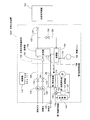
- FIG. 1 is a block diagram showing an example of a schematic configuration of the hydrogen generator according to the first embodiment of the present invention.
- FIG. 2 is a flowchart showing an example of an operation during stop processing in the hydrogen generator of the first embodiment of the present invention.
- FIG. 3 is a flowchart showing an outline of an operation when the operation is stopped in the hydrogen generator of the first embodiment of the present invention.
- FIG. 4 is a flowchart showing an example of an operation when the operation of the hydrogen generator according to the first modification of the first embodiment of the present invention is stopped.
- FIG. 5 is a block diagram showing an example of a schematic configuration of a hydrogen generator according to a fourth modification of the first embodiment of the present invention.
- FIG. 6 is a block diagram showing an example of a schematic configuration of the hydrogen generator according to the fifth modification of the first embodiment of the present invention.
- FIG. 7 is a block diagram showing an example of a schematic configuration of a hydrogen generator according to a sixth modification of the first embodiment of the present invention.
- FIG. 8 is a flowchart showing an outline of the operation when the hydrogen generator according to the seventh modification of the first embodiment of the present invention is stopped.
- FIG. 9 is a block diagram showing an example of a schematic configuration of the hydrogen generator according to the eleventh modification of the first embodiment of the present invention.
- FIG. 10 is a block diagram showing an example of a schematic configuration of a hydrogen generator according to a twelfth modification of the first embodiment of the present invention.
- FIG. 11 is a block diagram which shows an example of schematic structure of the hydrogen generator concerning the 13th modification of 1st Embodiment of this invention.
- FIG. 12 is a block diagram showing an example of a schematic configuration of a hydrogen generator according to a fourteenth modification of the first embodiment of the present invention.
- FIG. 13 is a block diagram illustrating an example of a schematic configuration of the hydrogen generator and the fuel cell system according to the second embodiment of the present invention.
- FIG. 14 is a flowchart showing an outline of an operation when the power generation operation is stopped in the hydrogen generator and the fuel cell system according to the second embodiment of the present invention.
- FIG. 12 is a block diagram showing an example of a schematic configuration of a hydrogen generator according to a fourteenth modification of the first embodiment of the present invention.
- FIG. 13 is a block diagram illustrating an example of a schematic configuration of the hydrogen generator and the fuel cell system according to the second embodiment of the present invention.
- FIG. 14 is a flowchart showing an outline of an operation when the power generation
- FIG. 15 is a flowchart showing an outline of a path switching operation when the power generation operation of the hydrogen generator and the fuel cell system according to the second embodiment of the present invention is stopped.
- FIG. 16 is a block diagram showing a schematic configuration of a portion different from FIG. 13 in the fuel cell system according to the first modification of the second embodiment of the present invention.
- FIG. 17 is a block diagram showing a schematic configuration of a portion different from FIG. 13 in the fuel cell system according to the second modification of the second embodiment of the present invention.
- the hydrogen generator (for example, hydrogen generator 100 [FIG. 1] or hydrogen generator 1002 [FIG. 5]) in the first embodiment of the present invention generates a hydrogen-containing gas by a reforming reaction using raw materials.
- a reformer eg, reformer 102
- a combustor eg, combustor 104
- an air supply eg, combustion fan 106
- a first heat exchanger for example, the first heat exchanger 108 for recovering heat from the flue gas discharged from the combustor, and a first heat medium that receives heat recovered from the flue gas in the heat exchanger
- a first heat medium path for example, the first heat medium path 110
- a first pump for example, the first pump 112 for flowing the first heat medium in the first heat medium path
- a first Heat storage for storing heat recovered by heat medium (For example, the heat accumulator 140 or the heat accumulator 141) and the air supply unit in a state where the combustor is not combusting at the time of stoppage (for example, the state after Step S12 of FIG. 2: after the combustor stops combustion).
- Control for operating the first pump in a cooling process (for example, step S13 in FIG. 2: a process in which the air supply unit operates without burning the combustor) which is a process for cooling at least the reformer with the supplied air. (For example, controller 114).
- the “raw material” includes at least an organic compound having hydrogen and carbon as constituent elements, and specifically includes hydrocarbons such as methane, propane gas, and city gas, and alcohols such as methanol and ethanol. Is mentioned.
- the air supplied by the air supplier becomes combustion air when the combustor is combusting, and is cooled when the combustor is not combusting. Air for use.
- the “first heat exchanger” may be any device that allows heat exchange between the combustion exhaust gas and the first heat medium.
- the heat in the combustion exhaust gas is recovered and used by heat exchange.
- the heat medium path is more preferably configured to be connected to a heat accumulator (hot water storage tank or the like) or to be connected to a floor heating path.
- the “first heat medium” is a liquid heat medium, and for example, liquid water or antifreeze can be used.
- the “first pump” may be any device that drives the first heat medium so that the first heat medium flows in the first heat medium path.
- the “controller” may be configured with, for example, one CPU (centralized control) or may be configured with a plurality of CPUs (distributed control).
- Cooling step refers to a step of cooling at least the reformer with air supplied from the air supply unit when the combustor is not combusting when stopped.
- the air supplier may operate continuously or intermittently.
- the air supplier functions as a refrigerant (air) supplier for cooling the reformer.
- the air supply device functions as a supply device for combustion air.
- the state where combustion is not performed means, for example, a state where no flame is generated in the combustor and combustion heat (reaction heat generated by an oxidation reaction of fuel) is not generated.
- the purpose of operating the first pump in the cooling process is to flow the heat medium through the heat medium path, thereby promoting heat exchange in the heat exchanger (heat recovery from the exhaust air to the heat medium).
- the purpose is to cool the exhausted air recovered.
- the first pump may also operate continuously or intermittently.
- the “raw material feeder” may be any device that adjusts the flow rate of the raw material supplied to the reformer, and for example, a booster pump or a flow rate adjusting valve may be used.
- the hydrogen generator according to the second embodiment of the present invention is the same as the hydrogen generator according to the first embodiment of the present invention, in which a raw material supplier (for example, a booster pump 116) supplies the raw material to the reformer.
- the raw material is supplied from the raw material feeder to the reformer at the start-up, and the raw material that has passed through the reformer is combusted in the combustor to heat the reformer, and the controller is at least the reformer
- the cooling process is continued until the temperature of is lower than the standby temperature.
- standby temperature is defined as the temperature at which the hydrogen generator stop process is completed and the next start-up standby state can be entered.
- a predetermined temperature of 500 ° C. or lower can be set as the standby temperature.
- the temperature of the reformer is not only a temperature detector (for example, the third temperature detector 138) that directly detects the temperature of the reformer, but also a detector (for example, a detector that indirectly detects the temperature of the reformer).
- a timer that measures the time since the stop process was started).
- the hydrogen generator in the third embodiment of the present invention is the hydrogen generator in the first embodiment of the present invention, wherein the controller cools until the temperature of the reformer falls below the purgeable temperature. Continue the process.
- the inside of the reformer can be purged more quickly than when the above cooling process is not performed, while reducing the possibility of thermal deterioration of the exhaust gas heat exchanger and the burns of people near the exhaust port. It becomes possible to decrease to a certain temperature.
- the “purgeable temperature” is a problem that, for example, carbon is deposited on the surface of the reforming catalyst in the reformer even when the raw material is passed in order to purge the interior of the reformer.
- the gas used for the purge is not limited to the raw material, and may be, for example, an inert gas such as nitrogen.
- the hydrogen generator according to the fourth embodiment of the present invention is the hydrogen generator according to the third embodiment of the present invention, wherein the controller is configured such that the temperature of the reformer is equal to or lower than the purgeable temperature during an abnormal stop. The cooling process is continued until
- the temperature can be lowered to a temperature that can be purged.
- the temperature of the reformer quickly decreases to a temperature at which the maintenance man can work, the maintainability is improved.
- abnormal stop means equipment failure (eg, temperature detector failure, CO sensor failure, combustion air supply failure), gas leakage abnormality (eg, flammable gas leakage abnormality), temperature
- a detection temperature abnormality of the detector for example, an excessive temperature increase or an excessive temperature decrease of the reforming temperature
- the hydrogen generator in the fifth embodiment of the present invention (for example, the hydrogen generator 1004 [FIG. 6]) is the same as the first embodiment of the hydrogen generator in the first embodiment of the present invention.
- a first switch for example, a second bypass path 127) that bypasses the heat exchanger and a first switch that switches an inflow destination of the first heat medium that has passed through the first heat exchanger between the heat accumulator and the bypass path (for example, A three-way valve 129) and a first temperature detector (for example, the first temperature detector 123) that detects the temperature of the first heat medium that has passed through the first heat exchanger. First until the temperature detected by the first temperature detector is equal to or higher than the first threshold.
- the replacement unit to keep the bypass path side.
- the first heat medium recovered from the exhaust air in the cooling step is suppressed from flowing into the regenerator in a low temperature state, and the temperature drop inside the regenerator can be suppressed.
- the “first threshold value” is, for example, a heat storage lower limit temperature for preventing the temperature of the heat medium supplied to the heat accumulator from dropping too much (in the case where the heat accumulator is a hot water storage tank, the hot water storage lower limit temperature). is there.
- the hydrogen generator (eg, hydrogen generator 1002 [FIG. 5]) according to the sixth embodiment of the present invention is the same as the hydrogen generator according to the first embodiment of the present invention.
- a second heat exchanger (for example, second heat exchanger 135) for recovering heat from the first heat medium, and a second heat medium that receives heat recovered from the first heat medium in the second heat exchanger.
- a second heat medium path (for example, the second heat medium path 143) that flows, a second pump (for example, the second pump 142) for flowing the second heat medium in the second heat medium path, and a second heat A bypass path (for example, a third bypass path) that connects the second heat medium path upstream of the exchanger and the second heat medium path downstream of the second heat exchanger and bypasses the heat accumulator (for example, the heat accumulator 141).
- a second switch for example, a three-way valve 144) that switches between the heat exchanger and the bypass path, and a second temperature detector (for example, a second temperature) that detects the temperature of the second heat medium that has passed through the second heat exchanger.
- a second temperature detector for example, a second temperature
- the heat accumulator stores the second heat medium that has passed through the second heat exchanger
- the controller detects the temperature detected by the second temperature detector in the cooling step.
- the second switch is maintained on the bypass path side until the threshold value of 1 is exceeded.
- the second heat medium recovered from the exhaust air in the cooling step is suppressed from flowing into the regenerator in a low temperature state, and the temperature drop inside the regenerator can be suppressed.
- the “second heat exchanger” may be any device as long as heat exchange can be performed between the first heat medium and the second heat medium.
- the heat in the first heat medium is recovered and used by heat exchange. Examples of the use of the recovered heat include hot water supply and floor heating.
- the second heat medium path is more preferably configured to be connected to a heat accumulator (hot water storage tank or the like) or to be configured to be connected to a floor heating path.
- the “second heat medium” is a liquid heat medium, and for example, liquid water, antifreeze, or the like can be used.
- the “second pump” may be any device that drives the second heat medium so that the second heat medium flows in the second heat medium path.
- the hydrogen generator (for example, hydrogen generator 1004 [FIG. 6]) in the seventh embodiment of the present invention is the same as the first heat exchanger in the hydrogen generator in the first embodiment of the present invention.
- a first temperature detector for example, the first temperature detector 123 that detects the temperature of the first heat medium that has passed is provided, and the controller operates the first pump based on the detected temperature of the first temperature detector.
- a first heat recovery operation for controlling the first heat recovery operation and a second heat recovery operation for forcibly controlling the operation amount of the first pump to a predetermined amount or more regardless of the temperature detected by the first temperature detector. Run with.
- the temperature of the first heat medium is controlled to an appropriate temperature for storing in the heat accumulator, and the exhaust air recovered from the reformer is heated.
- a heat recovery operation is performed regardless of the temperature of the first heat medium. That is, it is possible to reduce the possibility that a person near the exhaust port will be burned more than the conventional hydrogen generator while considering the use of the recovered heat by the first heat medium.
- the hydrogen generator in the eighth embodiment of the present invention (for example, the hydrogen generator 1004 [FIG. 6]) is the same as the hydrogen generator in the seventh embodiment of the present invention.
- the first switch In the recovery operation, when the detected temperature of the first temperature detector is equal to or higher than the first threshold, the first switch is switched to the heat accumulator side, and the detected temperature of the first temperature detector is smaller than the first threshold. If the threshold is less than 2, the first switch is switched to the bypass path side.
- the temperature of the first heat medium supplied to the heat accumulator is controlled to an appropriate temperature, and the inflow of the low temperature first heat medium to the heat accumulator is suppressed.
- the hydrogen generator for example, hydrogen generator 1006 [FIG. 7]
- the hydrogen generator in the ninth embodiment of the present invention is the same as that in the first heat medium path in the hydrogen generator in the first embodiment of the present invention.
- a second heat exchanger for recovering heat from the first heat medium, a second heat medium path through which a second heat medium that receives heat recovered from the first heat medium in the second heat exchanger flows,
- a second pump for flowing the second heat medium in the heat medium path; and a second temperature detector for detecting the temperature of the second heat medium that has passed through the second heat exchanger.
- a heat accumulator that stores the second heat medium that has passed through the heat exchanger, and the controller controls a first heat recovery operation for controlling an operation amount of the second pump based on a temperature detected by the second temperature detector; Regardless of the temperature detected by the second temperature detector, the operation amount of the second pump is forcibly increased to a predetermined amount or more.
- a second heat recovery operation Gosuru executed in that order.
- the temperature of the second heat medium is controlled to an appropriate temperature for storing in the heat accumulator, and the exhaust air recovered from the reformer is When the temperature is lowered, a heat recovery operation is performed regardless of the temperature of the second heat medium. That is, it is possible to promote the cooling of the reformer while considering the use of the stored heat of the recovered heat by the second heat medium.
- a hydrogen generator for example, hydrogen generator 1006 [FIG. 7] in the tenth embodiment of the present invention is the same as the second heat exchanger in the hydrogen generator in the ninth embodiment of the present invention.
- a bypass path connecting the upstream second heat medium path and the second heat medium path downstream of the second heat exchanger, bypassing the heat accumulator, and an inflow destination of the second heat medium passing through the second heat exchanger
- a second switching device that switches between the heat storage device and the bypass path, and the controller switches the second heat recovery operation when the detected temperature of the second temperature detector is equal to or higher than the first threshold value.
- the switch is switched to the bypass path side.
- the temperature of the second heat medium supplied to the heat accumulator is controlled to an appropriate temperature, and the inflow of the low-temperature second heat medium to the heat accumulator is suppressed.
- the hydrogen generator in the eleventh embodiment of the present invention (for example, the hydrogen generator 100 [FIG. 1]) is modified with the raw material after the cooling step in the hydrogen generator in the first embodiment of the present invention.
- the raw material purging operation for purging the inside of the mass device the gas sent from the reformer is combusted in the combustor and the first pump is operated, and the controller is in the raw material purging operation rather than in the cooling process. This increases the amount of operation of the first pump.
- the gas delivered from the reformer is combusted in the combustor, so that the retained heat amount of the gas flowing through the combustion exhaust gas path is larger than that in the reformer cooling process.
- the first pump is controlled so that the amount of heat recovered during the raw material purging operation is larger than that during the cooling step. The possibility of burns in the vicinity of the mouth is reduced.
- the hydrogen generator in the twelfth embodiment of the present invention (for example, the hydrogen generator 1002 [FIG. 5]) is the same as the hydrogen generator in the first embodiment of the present invention in the first heat medium path.
- the gas delivered from the reformer is combusted in the combustor, so that the amount of heat retained in the gas flowing through the combustion exhaust gas path is greater than in the cooling process of the reformer.
- the second pump is controlled so that the amount of heat recovery is greater during the raw material purge operation than during the cooling step. The possibility of thermal deterioration and burns in the vicinity of the exhaust port is reduced.
- the fuel cell system according to the thirteenth embodiment of the present invention includes any one of the hydrogen generators according to the first to twelfth embodiments of the present invention.
- a fuel cell (for example, a fuel cell 250) that generates power using the hydrogen-containing gas generated by the hydrogen generator.
- a polymer electrolyte fuel cell (PEFC) or a solid oxide fuel cell (SOFC) is used as the “fuel cell”.
- PEFC polymer electrolyte fuel cell
- SOFC solid oxide fuel cell
- an indirect internal reforming type that normally has a reforming unit that performs reforming reaction and a fuel cell unit, and an internal reforming type that also performs reforming reaction inside the fuel cell body Any of these may be used. That is, a form in which the reformer is incorporated in the fuel cell may be employed, and the fuel cell system of the present invention includes such a form.
- a fuel cell system according to the fourteenth embodiment of the present invention is a fuel cell system according to the thirteenth embodiment of the present invention. It is configured to perform a cathode purge operation in which the gas that has been supplied and passed through the cathode of the fuel cell is used to burn in the combustor, and the cooling step is a cooling step after completion of the cathode purge operation.
- the upstream side of the booster pump 116 is connected to a source gas supply source (for example, city gas infrastructure).
- the downstream side of the booster pump 116 is connected to the reformer 102 via the raw material gas supply channel 120.
- a first on-off valve 118 is provided in the source gas supply flow path 120.
- the inlet of the reforming water pump 117 is connected to a water supply source (for example, a water tank that stores condensed water in the combustion exhaust gas generated by the first heat exchanger 108, a water infrastructure, etc.).
- a water supply source for example, a water tank that stores condensed water in the combustion exhaust gas generated by the first heat exchanger 108, a water infrastructure, etc.
- the outlet of the reforming water pump 117 is connected to the evaporator 103, and the evaporator 103 is connected to the reformer 102.
- a second open / close valve 119 is provided in the reforming water supply path 121 between the reforming water pump 117 and the evaporator 103.
- the gas sent from the reformer 102 is configured to be sent as it is from the hydrogen generator main body 105, but is generated by the reformer 102 downstream of the reformer 102.
- a shifter having a shift catalyst for example, a Cu—Zn-based catalyst
- a CO remover having an oxidation catalyst for example, a Pt-based catalyst
- a form may be adopted.
- the hydrogen-containing gas outlet of the hydrogen generator main body 105 is connected to the hydrogen utilization device 150 via the fuel gas supply path 122.
- a third on-off valve 128 is provided in the fuel gas supply path 122.
- a first bypass path 126 that branches off in the middle of the fuel gas supply path 122 and bypasses the hydrogen using device 150 and is connected to the combustor 104 is provided.
- the first bypass path 126 is provided with a fifth on-off valve 132. ing.
- the combustion fan 106 is connected to the combustor 104 via a combustion air supply path 134.
- a combustion exhaust gas path 136 through which the combustion exhaust gas sent from the combustor 104 flows is provided.
- the combustion exhaust gas path 136 is configured to be able to exchange heat with at least the reformer 102, and the reformer 102 is heated by the combustion exhaust gas in the combustion exhaust gas.
- these reactors may be configured to be heated by the combustion exhaust gas.
- the combustion exhaust gas path 136 may be configured to be able to exchange heat with the evaporator 103.
- combustion exhaust gas path 136 passes through the inside of the first heat exchanger 108.
- the first heat exchanger 108 also passes through the first heat medium path 110 through which the first heat medium that recovers heat from the combustion exhaust gas in the heat exchanger 110 flows.
- a first pump 112 is provided in the first heat medium path 110.
- the combustion exhaust gas in the combustion exhaust gas path 136 and the heat medium in the first heat medium path 110 are configured to be able to exchange heat with each other in the first heat exchanger 108.
- the first heat medium that has passed through the first heat exchanger 108 is stored in the heat accumulator 140.
- the first pump 112 sends the first heat medium taken out from the heat accumulator 140 to the first heat exchanger 108.
- the third temperature detector 138 is attached to the reformer 102, detects the temperature of the reformer 102, and sends the result to the controller 114.
- the controller 114 includes a CPU, a memory, and the like, and is electrically connected to and controls the on-off valves 118, 119, 128, 132, the combustion fan 106, the first pump 112, the booster pump 116, and the like.
- the hydrogen utilization device 150 in the present embodiment may be, for example, a hydrogen storage tank, but is not limited to this, and any device that uses hydrogen, such as a fuel cell, may be used.
- Each on-off valve can be, for example, an electromagnetic valve.
- a temperature sensor such as a thermistor can be used.
- the first on-off valve 118 and the second on-off valve 119 are open.
- the booster pump 116 supplies the source gas to the reformer 102 via the source gas supply path 120.
- the reformed water is supplied to the evaporator 103 via the reformed water supply path 121.
- the reformer 102 is heated by the combustion exhaust gas from the combustor 104. In the evaporator 103, the reformed water becomes steam. In the reformer 102, a hydrogen-containing gas (fuel gas) is generated from the steam and the raw material gas by a steam reforming reaction. During the start-up process, the generated hydrogen-containing gas is supplied to the combustor 104 as a combustion gas via the first bypass passage 126, with the third on-off valve 128 closed by the controller 114, Control is performed so that the fifth on-off valve 132 is opened.
- a hydrogen-containing gas fuel gas
- the generated hydrogen-containing gas is supplied to the combustor 104 as a combustion gas via the first bypass passage 126, with the third on-off valve 128 closed by the controller 114, Control is performed so that the fifth on-off valve 132 is opened.
- the third on-off valve 128 is opened while the fifth on-off valve 132 is kept open, the supply of the hydrogen-containing gas to the hydrogen utilization device 150 is started, and the hydrogen generation operation is started. Even during the hydrogen generation operation, a part of the hydrogen-containing gas sent from the hydrogen generator main body 105 is supplied to the combustor 104 through the first bypass passage 126 and burned, and the reformer 102 is modified. Maintain temperature suitable for quality reaction.
- the flue gas generated in the combustor 104 flows through the flue gas path 136, the flue gas is cooled in the first heat exchanger 108, the moisture in the flue gas is condensed, and then the hydrogen generation apparatus 100 through the exhaust port 137. It is discharged outside the housing.
- the controller 114 When there is an activation request in a standby state waiting for activation, the controller 114 outputs an activation instruction and starts an activation process including a temperature raising operation of the hydrogen generator main body 105 of the hydrogen generator 100.
- the start-up process is performed until the temperature of the hydrogen generator reaches a temperature suitable for generating a hydrogen-containing gas containing high-concentration hydrogen (H 2 gas) stably by the hydrogen generator.
- H 2 gas high-concentration hydrogen
- the raw material supplier boost pump 116
- the raw material supplier is operated to supply the raw material to the reformer 102, while the third on-off valve 128 is closed and the fifth on-off valve 132 is opened, and the first bypass path is opened.
- the combustible gas supplied to the combustor 104 is burned through 126, and the temperature raising operation of the hydrogen generator main body 105 including the reformer 102 is executed.
- the second on-off valve 119 is opened and the reforming water is
- the supply unit (reformed water pump 117) is operated to start supplying reformed water to the evaporator 103.
- the evaporable temperature is set as a temperature of 100 ° C. or higher, and is configured to determine whether or not the temperature detected by the third temperature detector 138 is equal to or higher than the evaporable temperature.
- a temperature threshold value for determining whether or not the temperature is equal to or higher than the evaporable temperature is set for the detected temperature.
- the temperature raising operation is continued until the temperature of the reformer 102 reaches a stable temperature suitable for a reforming reaction capable of generating a hydrogen-containing gas containing hydrogen at a high concentration.
- the start-up process of the hydrogen generator 100 is completed, and the controller 114 keeps the fifth on-off valve 132 open. Then, the third on-off valve 128 is opened, and the supply of the hydrogen-containing gas to the hydrogen using device 150 is started.
- a shifter or an oxidation reaction that reduces carbon monoxide by a shift reaction is used as a reactor for reducing carbon monoxide in the hydrogen-containing gas produced by the reformer 102 in the hydrogen generator main body 105.
- a shifter or an oxidation reaction that reduces carbon monoxide by a shift reaction is used as a reactor for reducing carbon monoxide in the hydrogen-containing gas produced by the reformer 102 in the hydrogen generator main body 105.
- a shifter or an oxidation reaction that reduces carbon monoxide by a shift reaction is used as a reactor for reducing carbon monoxide in the hydrogen-containing gas produced by the reformer 102 in the hydrogen generator main body 105.
- a shifter or an oxidation reaction that reduces carbon monoxide by a shift reaction is used as a reactor for reducing carbon monoxide in the hydrogen-containing gas produced by the reformer 102 in the hydrogen generator main body 105.
- FIG. 3 is a flowchart showing an outline of the operation when the hydrogen generator of the first embodiment of the present invention is stopped.
- the outline of the operation at the time of the stop process in the hydrogen generator 100 of the present embodiment will be described with reference to FIG.
- step S101 it is determined whether or not a hydrogen generation stop command has been generated. If so, the operations of the booster pump 116 and the reforming water pump 117 are stopped. At the same time, the first on-off valve 118 and the second on-off valve 119 are closed, and the supply of the raw material gas and the reforming water is stopped (step S102).
- step S103 combustion in the combustor 104 (burner) is stopped.
- an operation is performed to discharge the combustible gas remaining in the combustor 104 to the outside of the housing by the air supplied from the combustion fan 106 after extinguishing the fire.
- the combustion stop process of the vessel 104 is completed.
- Step S104 Cooling step). Note that the operations of the combustion fan 106 and the first pump 112 in this cooling step may be continuous or intermittent.
- the temperature t1 of the reformer 102 is detected using the third temperature detector 138 (step S105), and it is determined whether or not t1 is equal to or lower than the standby temperature (for example, 500 ° C. or lower) ( Step S106).
- the standby temperature for example, 500 ° C. or lower
- step S106 If the decision result in the step S106 is YES, the operation of the combustion fan 106 is stopped and the operation of the first pump 112 is stopped (step S107), the stop process is completed, and the hydrogen generator 100 enters a standby state. The process proceeds (step S108).
- step S106 If the decision result in the step S106 is NO, the process returns to the step S105.
- standby temperature is defined as a temperature at which the hydrogen generator stop process is completed and the next start-up standby state (standby state where the start-up process starts immediately if there is a start-up request) can be entered. Is done. As an example, even when the starting process is started and the raw material gas is supplied into the reformer 102, the temperature at which carbon does not precipitate on the surface of the reforming catalyst provided in the reformer or the downstream path thereof can be cited. It is done. Specifically, as the internal temperature of the reformer 102, a predetermined temperature of 500 ° C. or less can be set as the standby temperature.
- the cooling process and the heat recovery operation are continued until the temperature detected by the third temperature detector 138 reaches the standby temperature.
- the present invention is not limited to this.
- the cooling step is performed to a temperature at which the purge operation can be performed (purgeable temperature).
- purgeable temperature refers to, for example, the temperature of the reformer 102 by being discharged from the hydrogen generator 105 and combusting in the combustor 104 in the purge operation when the replacement gas is a raw material.
- it is set as a temperature that does not exceed the upper limit temperature at which the source gas does not precipitate carbon. Specifically, it is set as a temperature (for example, 300 ° C.) equal to or lower than the value obtained by subtracting the temperature rise of the reformer 102 in the purge operation from the upper limit temperature of the reformer 102 that does not cause carbon deposition from the raw material gas. .
- the pump for flowing the first heat medium is operated in the reformer cooling step using combustion air. Therefore, the exhaust air flowing through the combustion exhaust gas path 136 that has been heated by cooling the reformer 102 and the like is not directly discharged outside the housing of the hydrogen generator 100 but is cooled in the first heat exchanger 108. After that, it is discharged from the exhaust port 137 for combustion exhaust gas to the outside of the housing of the hydrogen generator 100. Therefore, even if a person is present near the exhaust port of the combustion exhaust gas, the possibility of being burned by the gas discharged from the exhaust port in the cooling process is reduced as compared with the conventional hydrogen generator. Further, in the cooling step, the exhaust air is cooled by the heat medium in the first heat exchanger 108, so that peripheral components (O-ring, packing, etc.) of the first heat exchanger 108 are less likely to be thermally deteriorated.
- peripheral components O-ring, packing, etc.
- the hardware configuration of the hydrogen generator of the first modification can be the same as that of the hydrogen generator 100 shown in FIG. Since the operations of the hydrogen generation operation and the start-up process in the present modification can be the same as those described above for the hydrogen generator 100, description thereof will be omitted.
- FIG. 4 is a flowchart showing an outline of the operation when the hydrogen generator according to the first modification of the first embodiment of the present invention is stopped.
- the outline of the operation at the time of the stop process in the hydrogen generator of the present modification will be described with reference to FIG.
- the following operations are performed by controlling each device of the hydrogen generator by the controller.
- step S201 it is determined whether or not a hydrogen generation stop command has been generated. If so, the first on-off valve 118 and the second on-off valve 119 are generated. Is closed, the supply of the raw material gas and the reforming water is stopped, the fifth on-off valve 132 is closed, and the combustion of the combustor 104 (burner) is stopped (step S202).
- step S203 cooling process
- the temperature of the reformer 102 is detected using the third temperature detector 138, and it is determined whether or not the detected temperature is equal to or lower than a purgeable temperature (for example, 300 ° C. or lower) (step S204). ).
- a purgeable temperature for example, 300 ° C. or lower
- step S205 a purge operation is started (step S205). That is, the first on-off valve 118 and the fifth on-off valve 132 are opened, and the booster pump 116 is operated to supply the raw material gas to the reformer 102. The raw material gas discharged from the reformer is supplied to the combustor 104 via the first bypass path 126 and burned in the combustor 104.
- the elapsed time is measured, and it is determined whether the elapsed time is equal to or longer than the preset purge operation time. If the determination result is YES, the operation of the booster pump 116 is stopped, the first on-off valve 118 and the fifth on-off valve 132 are closed, and the purge operation is stopped (step S206).
- step S207 When the purge operation is stopped, the operations of the combustion fan 106 and the first pump 112 are stopped (step S207), and the stop process is completed (end).
- the hydrogen generator of the second modified example is characterized in that the cooling process and the heat recovery operation similar to those of the hydrogen generator of the first modified example and the subsequent purging operation are executed at the time of abnormal stop.
- Abnormalities in this modification include equipment failure (eg, temperature detector failure, CO sensor failure, and combustion air supply failure), gas leakage abnormality (eg, flammable gas leakage abnormality), temperature detector. Detection temperature abnormalities (for example, overheating and overcooling of the reforming temperature) are defined. Note that these abnormalities are examples, and some of these abnormalities may be defined as abnormalities, and abnormalities other than these abnormalities may be defined as abnormalities.
- Examples of abnormalities in which a failure of the temperature detector is assumed include, for example, when the third temperature detector 138 is a thermistor, these detected values become values indicating short circuit or disconnection.
- the same cooling process, heat recovery operation, and subsequent purge operation as those in Modification 1 are executed as an abnormal stop process corresponding to the abnormality.
- the abnormality assumed to be a failure of the CO sensor means that when a CO sensor (not shown) provided in the combustor 104 is a contact combustion type sensor, the detected value of this sensor is a value indicating a disconnection of the electrical resistance. Abnormalities are mentioned. In the present modification, the same cooling process, heat recovery operation, and subsequent purge operation as those in Modification 1 are executed as an abnormal stop process corresponding to the abnormality.
- the abnormality that is assumed to be a failure of the combustion air supply device means that, for example, the rotation speed of the combustion fan 106 is outside the allowable range with respect to the operation amount from the controller 114 (for example, a set operation amount corresponding to the target rotation number In contrast, there is an abnormality in which the target rotational speed is not reached for a predetermined time or more even if the operation amount is increased. Such an abnormality may occur when a desired rotation speed cannot be obtained with respect to the command value of the operation amount due to motor deterioration, and is thus considered as an abnormality in which a failure of the combustion fan 106 is assumed. In the present modification, the same cooling process, heat recovery operation, and subsequent purge operation as those in Modification 1 are executed as an abnormal stop process corresponding to the abnormality.
- the flammable gas leakage abnormality is an abnormality in which a flammable gas sensor provided in the hydrogen generator detects a flammable gas.
- a flammable gas sensor provided in the hydrogen generator detects a flammable gas.
- the cooling process, the heat recovery operation, and the subsequent purge operation similar to those of the first modification are executed as an abnormal stop process corresponding to the abnormality.
- an abnormality determination device built in the controller 114 functions as an abnormality detector, and is different from the abnormality of the detector.
- a hydrogen generation stop command is output when the above abnormality is detected. Thereafter, a stop process similar to that shown in steps S201 to S207 of FIG. 4 is performed, and after the stop process is completed, a transition is made to a start non-permitted state (end).
- the start disapproval state is a state in which the start of the fuel cell system is permitted even when a start request is generated, and the start command is not output by the controller. For example, even if the user operates the key operation unit of the remote controller to make an operation start request so that the user starts the hydrogen generator, the controller can perform the above-described process for starting the hydrogen generator. It means to be in a state that is not.
- the configuration and operation of the hydrogen generator of the third modified example can be the same as the configuration and operation of the first modified example and the second modified example except for the above points, and thus detailed description is omitted. To do.
- the fourth modification is characterized in that in the cooling process of the hydrogen generator of Embodiment 1, the retained heat of the exhaust air that has cooled the reformer is recovered in the secondary cooling system.
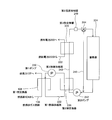
- FIG. 5 is a block diagram showing an example of a schematic configuration of the hydrogen generator 1002 in the present modification.
- elements common to FIG. 1 are denoted by the same reference numerals and names, and detailed description thereof is omitted.
- the second heat exchanger 135 is a heat exchanger for recovering heat from the first heat medium in the first heat medium path 110.
- the second heat medium path 143 is a path through which the second heat medium that receives heat recovered from the first heat medium in the second heat exchanger 135 flows.
- the second pump 142 is a pump for flowing the second heat medium in the second heat medium path 143.
- the hydrogen generator 1002 of this modification operates not only the first pump but also the second pump in the cooling process, and the retained heat of the exhaust air that has cooled the reformer 102 is finally recovered in the second heat medium. And stored in the heat accumulator 141.
- the configuration of the hydrogen generator of the present modification and the heat recovery operation in the cooling process may be applied to the hydrogen generators of the first to third modifications. Further, even when the raw material purge operation is executed as in the hydrogen generators of the first to third modifications, it is preferable to operate the first pump 112 and the second pump 142. Further, similarly to the hydrogen generator of the third modification, the controller 114 controls the operation amounts of the first pump 112 and the second pump 142 during the raw material purge operation to be larger than the operation amounts during the cooling process. Is preferred.
- the hydrogen generator of the fifth modification includes a bypass path that bypasses the heat accumulator, a first switch that switches an inflow destination of the first heat medium between the heat accumulator and the bypass path, and a temperature of the first heat medium. And a first temperature detector to be detected. In the cooling step, the first switch is maintained on the bypass path side until the temperature detected by the first temperature detector becomes equal to or higher than a first threshold value. Since the operations of the hydrogen generation operation and the start-up process in the present modification can be the same as those described above for the hydrogen generator 100, description thereof will be omitted.
- FIG. 6 is a block diagram showing an example of a schematic configuration of the hydrogen generator 1004 according to this modification.
- elements common to FIG. 1 are assigned the same reference numerals and names, and detailed description thereof is omitted.
- the heat accumulator 140 is a heat accumulator that stores the first heat medium that has passed through the first heat exchanger 108.
- the second bypass path 127 connects the first heat medium path 110 upstream of the first heat exchanger 108 and the first heat medium path 108 downstream of the first heat exchanger 108 to bypass the heat accumulator 140. It is.
- the three-way valve 129 (first switcher) switches the inflow destination of the first heat medium that has passed through the first heat exchanger 108 between the heat accumulator 140 and the second bypass path 127.
- the first temperature detector 123 detects the temperature of the first heat medium that has passed through the first heat exchanger 108 and sends the detection result to the controller 114.
- the controller 114 controls the three-way valve 129 until the temperature detected by the first temperature detector becomes equal to or higher than a first threshold (for example, 65 ° C.) while operating the first pump 112 in the cooling process.
- a first threshold for example, 65 ° C.
- the “first threshold value” is, for example, a heat storage lower limit temperature for preventing the temperature of the heat medium supplied to the heat accumulator from being excessively lowered (in the case where the heat accumulator is a hot water storage tank, the hot water storage lower limit temperature). It is. Thereby, it is suppressed that the 1st heat medium which collect
- the hydrogen generator of the sixth modification differs from the hydrogen generator of the fifth modification in that the retained heat of the exhaust air that has cooled the reformer in the cooling step of the hydrogen generator is recovered in the secondary cooling system. It is configured. Specifically, a bypass path that bypasses the heat accumulator, a second switch that switches an inflow destination of the second heat medium between the heat accumulator and the bypass path, and a second temperature that detects the temperature of the second heat medium. And a second switching device is maintained on the bypass path side until the temperature detected by the second temperature detector becomes equal to or higher than the first threshold value in the cooling step. Since the operations of the hydrogen generation operation and the start-up process in the present modification can be the same as those described above for the hydrogen generator 100, description thereof will be omitted.
- FIG. 7 is a block diagram showing an example of a schematic configuration of the hydrogen generator 1006 according to this modification.
- elements common to FIG. 5 are denoted by the same reference numerals and names, and detailed description thereof is omitted.
- the heat accumulator 141 is a heat accumulator that stores the second heat medium that has passed through the second heat exchanger 135.
- the third bypass path 145 connects the second heat medium path 143 upstream of the second heat exchanger 135 and the second heat medium path 143 downstream of the second heat exchanger 135 to bypass the heat accumulator 141. It is.
- the three-way valve 144 (second switcher) switches the inflow destination of the second heat medium that has passed through the second heat exchanger 135 between the heat accumulator 141 and the third bypass path 145.
- the second temperature detector 148 detects the temperature of the second heat medium that has passed through the second heat exchanger 135 and sends the detection result to the controller 114.
- the controller 114 maintains the three-way valve 144 on the third bypass path 145 side until the temperature detected by the second temperature detector 148 becomes equal to or higher than a first threshold value (for example, 65 ° C.) in the cooling process. To do. Thereby, it is suppressed that the 1st heat medium which collect
- a first threshold value for example, 65 ° C.
- the hydrogen generator of the seventh modification includes a first heat recovery operation for controlling an operation amount of the first pump based on a temperature detected by the first temperature detector and a first temperature detection in the cooling step of the reformer.
- the second heat recovery operation for forcibly controlling the operation amount of the first pump to a predetermined amount or more regardless of the temperature detected by the container is performed in this order. Since the apparatus configuration and operation of the hydrogen generator of this modification can be the same as those of the fifth modification except for the above points, the description of common parts is omitted.
- FIG. 8 is a flowchart showing an outline of the operation when the hydrogen generator according to this modification is stopped.
- the outline of the operation at the time of the stop process in the hydrogen generator of the present modification will be described with reference to FIG.
- the following operations are performed by controlling each device of the hydrogen generator by the controller.
- step S301 it is determined whether or not a hydrogen generation stop command has been generated. If so, the operations of the booster pump 116 and the reforming water pump 117 are stopped. The first on-off valve 118 and the second on-off valve 119 are closed, the supply of the raw material gas and the reforming water is stopped, the fifth on-off valve 132 is closed, and the combustion of the combustor 104 (burner) is stopped. (Step S302).
- step S303 cooling process
- a first heat recovery operation is executed (step S304).
- the operation amount of the first pump 112 (the operation amount sent from the controller 114 to the first pump 112) is controlled based on the temperature detected by the first temperature detector 123. More specifically, the controller 114 uses the detected temperature of the first temperature detector 123 such that the temperature detected by the first temperature detector 123 is equal to or higher than a first threshold (for example, 65 ° C.), The operation amount of the first pump 112 is feedback controlled. If the detected temperature is lower than the first threshold, the amount of heat exchange is increased by decreasing the flow rate by decreasing the operation amount, and the temperature of the first heat medium is increased.
- a first threshold for example, 65 ° C.
- the second heat recovery operation is executed (step S305).
- the operation amount of the first pump 112 is forcibly controlled to a predetermined amount or more regardless of the temperature detected by the first temperature detector 123.
- the switching from the first heat recovery operation to the second heat recovery operation is performed by changing the reformer temperature to a predetermined temperature (for example, based on the temperature of the reformer detected by the third temperature detector 138, for example). 550 ° C.).
- the three-way valve 129 and the second bypass path side 127 can be omitted.
- the first heat medium is stored in the regenerator when the temperature can be controlled to an appropriate temperature for supplying to the regenerator, while cooling is preferentially performed when such control cannot be performed.
- the “second threshold value” is set as a value smaller than the first threshold value as described above, frequent switching of the three-way valve due to a change in the temperature of the first temperature detector is suppressed.
- the hydrogen generator of the ninth modification is configured to execute the first and second heat recovery operations in the cooling process of the hydrogen generator using the secondary cooling system.
- the first heat recovery operation for controlling the operation amount of the second pump 142 based on the detected temperature of the second temperature detector 148 and the forced detection regardless of the detected temperature of the second temperature detector 148.
- the second heat recovery operation for controlling the operation amount of the second pump 142 to a predetermined amount or more is performed in this order. Since the apparatus configuration and operation of the hydrogen generator of this modification can be the same as those of the sixth modification except for the above points, the description of common parts is omitted.
- the operation when the operation of the hydrogen generator of this modification is stopped is the same as that of the seventh modification, in which the first temperature detector 123 is replaced with the second temperature detector 148 and the first pump 112 is replaced with the second pump 142. Further, the first pump 112 is also controlled to operate together with the operation of the second pump 142, and other detailed description is omitted. Note that the first pump 112 is preferably controlled so as to be forcibly set to an operation amount equal to or greater than a predetermined value in the same way as the second pump 142 in at least the second heat recovery operation. The “predetermined value” may be the same as or different from the predetermined value when the operation amount of the first pump is controlled to a predetermined value or more in the second heat recovery operation. Good.
- the hydrogen generator of this modification can reduce the possibility of burns occurring near the exhaust port of the conventional hydrogen generator, while taking into account the use of the recovered heat by the second heat medium.
- the temperature of the second heat medium supplied to the heat accumulator is controlled to an appropriate temperature by the hydrogen generator of this modification, and the inflow of the low-temperature second heat medium to the heat accumulator is prevented. It is suppressed.
- the device configuration of the hydrogen generator 1008 of the eleventh modification is different from that of the fifth modification in that a radiator 131 is provided in the second bypass path 127, but other components are the same as those of the fifth modification. This is the same as the hydrogen generator 1004.
- FIG. 9 is a block diagram showing an example of a schematic configuration of the hydrogen generator 1008 of the present modification. 9, elements common to those in FIG. 6 are denoted by the same reference numerals and names, and detailed description thereof is omitted.
- the heat radiator 131 is provided on the second bypass path 127 and is configured to perform an active cooling operation.
- the “active cooling operation” is not passive cooling exemplified in natural heat dissipation to the atmosphere, but a refrigerant (for example, cooling by fan operation or cooling by circulating water). It refers to an operation of supplying air (such as air) to a position where the first heat medium can be cooled (for example, around the first heat medium path 110).
- a refrigerant for example, cooling by fan operation or cooling by circulating water. It refers to an operation of supplying air (such as air) to a position where the first heat medium can be cooled (for example, around the first heat medium path 110).
- the cooling process of the reformer when the operation of the hydrogen generator of this modification is stopped will be described.
- the combustion fan 106 is operated and the first pump 112 is operated to recover heat from the exhaust air that has cooled the reformer 102 by the first heat medium.
- the three-way valve 129 is maintained on the second bypass path 127 side, the cooling operation by the radiator 131 is turned on, and the first heat medium heated through the first heat exchanger is It flows through the bypass path 127 and is cooled via the radiator 131.
- the hydrogen generator of the present modification may be configured to execute the heat recovery operation in the cooling step in the same manner as in Modification 7. Specifically, as the first exhaust heat recovery operation, the three-way valve 129 is switched to the heat accumulator 140 side, and the operation amount of the first pump 123 is controlled based on the detected temperature of the first temperature detector 123, and thereafter As the second exhaust heat recovery operation, the three-way valve 129 is maintained on the second bypass path 127 side, and the cooling operation by the radiator 131 is executed.
- the device configuration of the hydrogen generator 1008 of the twelfth modified example is that the radiator 131 branches from the first heat medium path 110 without bypassing the heat accumulator 140 instead of the second bypass path 127 and the first heat medium path 110.
- the other components are the same as those of the hydrogen generator 1006 of the eleventh modification.
- FIG. 10 is a block diagram showing an example of a schematic configuration of a hydrogen generator 1010 according to a twelfth modification of the first embodiment of the present invention. 10, elements common to those in FIG. 6 are denoted by the same reference numerals and names, and detailed description thereof is omitted.
- the heat radiator 131 is provided on the first branch 133 and is configured to perform an active cooling operation in the same manner as in the eleventh modification.
- the first branch path 133 is a path that branches from the first heat medium path 110. In the present modification, the first branch path 133 branches from the first heat medium path 110 without bypassing the heat accumulator 140 and merges into the first heat medium path 110.
- the heat recovery operation in the cooling process of the hydrogen generator of this modification is the same as that of Modification 11, description thereof is omitted.
- route is not limited to an 11th modification and this example, If it is provided on the 1st branch path branched from a 1st heat-medium path
- the apparatus configuration of the hydrogen generator 1012 of the thirteenth modification corresponds to the case where the heat recovery operation in the cooling process of the hydrogen generator of the eleventh modification is performed in the secondary cooling system. Although it differs from the sixth modification in that a heat radiator 146 is provided in the bypass path 145, other components are the same as those of the hydrogen generator 1006 of the sixth modification.
- FIG. 11 is a block diagram showing an example of a schematic configuration of the hydrogen generator 1012 of the present modification. 11, elements common to those in FIG. 7 are denoted by the same reference numerals and names, and detailed description thereof is omitted.
- the heat radiator 146 is provided on the third bypass path 145 and is configured to perform an active cooling operation.
- the operation at the time of stopping the operation of the hydrogen generator of the present modification is performed by replacing the first temperature detector 123 with the second temperature detector 148 in the description of the eleventh modification.
- 112 is replaced with the second pump 142
- the three-way valve 129 is replaced with the three-way valve 144
- the second bypass path 127 is replaced with the third bypass path 145
- the first pump 112 is controlled to operate together with the operation of the second pump 142. Therefore, other detailed description is omitted.
- the first pump 112 is preferably controlled so as to be forcibly set to an operation amount equal to or greater than a predetermined value in the same way as the second pump 142 in at least the second heat recovery operation.
- the “predetermined value” may be the same as or different from the predetermined value when the operation amount of the first pump is controlled to a predetermined value or more in the second heat recovery operation. Good.
- the device configuration of the hydrogen generator 1014 of the fourteenth modified example is that the radiator 146 branches from the second heat medium path 143 without bypassing the heat accumulator 140 instead of the third bypass path 145, and the second heat medium path 143.
- the other components are the same as those of the hydrogen generator 1012 of the thirteenth modification.
- FIG. 12 is a block diagram showing an example of a schematic configuration of a hydrogen generator 1014 according to a fourteenth modification of the first embodiment of the present invention. 12, elements common to those in FIG. 7 are given the same reference numerals and names, and detailed description thereof is omitted.
- the heat radiator 146 is provided on the second branch 147 and performs an active cooling operation.
- the second branch path 147 is a path that branches from the second heat medium path 143.
- the second branch path 147 branches from the second heat medium path 143 without bypassing the heat accumulator 140 and merges into the second heat medium path 143.
- the controller 114 switches the switch to the radiator 146 side in the cooling process and operates the second pump 142.
- the second heat medium is efficiently cooled by the radiator 146, and the exhaust air is also efficiently cooled.
- route is not limited to a 13th modification and this example, If it is provided on the 2nd branch path branched from a 2nd heat-medium path
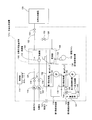
- FIG. 13 is a block diagram illustrating an example of a schematic configuration of the hydrogen generator and the fuel cell system according to the second embodiment of the present invention.
- the heat medium path through which the heat medium that receives the heat recovered from the combustion exhaust gas in the first heat exchanger 108 flows is the first heat medium path 232, and the heat in the heat medium path. Except for the point that the pump for driving the medium is the first pump 230, it has the same configuration as the hydrogen generator 100 of the first embodiment.
- the controller 114 is a cooling step that is a step of cooling the reformer 102 with air supplied from the air supply device in a state where the combustor 104 stops combustion when the power generation operation of the fuel cell system is stopped.
- the first pump 230 is operated.
- the fuel cell system 200 of the present embodiment includes a heat accumulator 224 that stores the heat medium that has passed through the first heat exchanger 108, a heat medium outlet in the first heat exchanger 108, and the first heat exchanger 108.
- a switch for example, a three-way valve 228, that switches between the heat medium and a heat medium temperature detector (for example, for detecting the temperature of the heat medium after being discharged from the first heat exchanger 108 and before flowing into the heat accumulator 224)
- the controller 114 supplies the heat medium discharged from the first heat exchanger 108 when the temperature detected by the heat medium temperature detector is equal to or higher than the first threshold value.
- the switching device is controlled so that when the temperature detected by the heat medium temperature detector is lower than the first threshold, the supply destination of the heat medium discharged from the first heat exchanger 108 is defined as the fifth bypass path 226.
- a configuration configured to control the switching device may be adopted. Thereby, it is suppressed that the 1st heat medium which collect
- the fuel cell 250 includes a cathode (not shown), supplies a raw material (for example, a raw material gas) to the cathode, and burns the raw material that has passed through the cathode in the combustor 104.
- the controller 114 may be configured to perform a purge operation, and the controller 114 may be configured to perform the cooling step and the heat recovery operation after the cathode purge operation is completed.
- cathode purge operation it is configured to burn in the combustor using the gas that has passed through the cathode. Therefore, heat is recovered quickly from the reformer, including the heat applied during cathode purge, and the reformer Can be cooled.
- the hydrogen generator 100 ′ in the fuel cell system 200 of the present embodiment is the same as the hydrogen generator 100 of the first embodiment, except that the hydrogen-using device 150 is a fuel cell 250 and the raw material gas does not pass through the reformer 102.
- a fourth bypass path 204 that connects the supply path 120 and the fuel cell 250, an oxidant gas discharge path 214 and a cathode purge gas discharge path 218 that connect the fuel cell 250 and the combustor 104 are provided, and the first pump 112 is The first pump 230 is used.
- Other parts, that is, parts common to the hydrogen generator 100 ′ and the hydrogen generator 100 are given the same reference numerals and names, and description thereof is omitted.
- the fuel cell 250 allows the hydrogen-containing gas (fuel gas) supplied from the hydrogen generator 100 ′ to flow through the anode gas flow path inside the fuel cell 250, and the oxidant gas supply device 206 (for example, a blower) oxidizes. Electric power is generated by flowing an oxidant gas (for example, air) supplied through the gas supply passage 210 through the cathode gas passage in the fuel cell 250.
- the anode gas flow path inside the fuel cell 250 has an inlet connected to the fuel gas supply path 122 and an outlet connected to the off-fuel gas path 124.
- the off fuel gas path 124 is connected to the first bypass path 126.
- a fourth on-off valve 130 is provided in the off fuel gas path 124.
- the cathode gas flow path inside the fuel cell 250 has an inlet connected to the oxidant gas supply path 210 and an outlet connected to the oxidant gas discharge path 214.
- the fourth bypass path 204 is a path for branching from the source gas supply path 120 to bypass the hydrogen generator main body 105 and supply the source material to the cathode channel of the fuel cell 250. This is a path that branches from the gas supply path 120 and connects the source gas supply path 120 between the booster pump 116 and the first on-off valve 118 and the oxidant gas supply path 210.
- a sixth on-off valve 202 is provided in the fourth bypass path 204.
- the oxidant gas supply path 210 is connected to the oxidant gas supply path 210 between the outlet of the oxidant gas supply unit 206 and the junction of the fourth bypass path 204 and the oxidant gas supply path 210 with a seventh opening / closing.
- a valve 208 is provided.
- the oxidant gas discharge path 214 is provided with an eighth on-off valve 212.
- the cathode purge gas discharge path 218 is a path for guiding the gas discharged from the cathode gas flow path of the fuel cell 250 to the combustor 104 during the cathode purge operation. Specifically, the cathode purge gas discharge path 218 is upstream of the eighth on-off valve 212.
- a branch from the oxidant gas discharge path 214 is connected to the combustor 104.
- a ninth on-off valve 216 is provided in the cathode purge gas discharge path 218.
- the cooling water path 222 passes through the inside of the fuel cell 250 and the inside of the third heat exchanger 220, and allows the cooling water to flow through the inside.
- a cooling water pump 221 is provided in the cooling water path 222.
- the cooling water pump 221 circulates the cooling water inside the cooling water path 222.
- the first heat medium path 232 connects the heat accumulator 224 and the first heat exchanger 108, passes through the inside of the first heat exchanger 108, and connects the first heat exchanger 108 and the third heat exchanger 220. Connect, pass through the inside of the third heat exchanger 220, and connect the third heat exchanger 220 and the heat accumulator 224.
- the first heat medium path 232 allows water as a heat medium to flow therethrough.
- the first heat medium path 232 is provided with a first pump 230.
- the first pump 230 circulates the heat medium inside the first heat medium path 232.
- the first heat medium path 232) connecting the outlet of the heater 220 and the inlet of the heat accumulator 224 is provided with a first temperature detector 223 and a three-way valve 228.
- the fifth bypass path 226 is a path for bypassing the heat accumulator 224 and circulating the heat medium to the first heat medium path 232 including the first heat exchanger 108 and the third heat exchanger 220.
- the three-way valve 228 is an example of a “switch”. Instead of the three-way valve 228, an opening / closing valve is provided in each of the first heat medium path 232 and the fifth bypass path 226 to switch between these opening / closing operations. Thus, a mode of functioning as a switching device may be adopted.
- the first temperature detector 223 detects the temperature of the heat medium in the first heat medium path 232 and sends the result to the controller 114.
- the controller 114 includes a CPU, a memory, etc., and the on-off valves 118, 119, 128, 130, 132, 202, 208, 212, 216, the combustion fan 106, the booster pump 116, the oxidant gas supply device 206, the cooling device. It is electrically connected to the water pump 221, the first pump 230, the three-way valve 228, etc., and controls them. That is, in this embodiment, the controller 114 is a controller of the hydrogen generator 100 ′ and a controller of the fuel cell system 200. However, it goes without saying that separate controllers may be provided for the hydrogen generator 100 'and the fuel cell system 200, and the number of controllers is not limited.
- the hydrogen generator 100 In the above power generation operation, the hydrogen generator 100 'performs a hydrogen generation operation. Details are the same as those in the first embodiment, and a description thereof will be omitted.
- the sixth on-off valve 202 and the ninth on-off valve 216 are closed to shut off the cathode purge path, the seventh on-off valve 208 and the eighth on-off valve 212 are opened, and the oxidant gas path is communicated. Is done.
- a hydrogen-containing gas fuel gas
- an oxidant gas for example, air
- Power generation is performed.
- the hydrogen-containing gas (off fuel gas) discharged from the anode of the fuel cell 250 is supplied to the combustor 104 via the off fuel gas path 124 and burned.
- the cooling water pump 221 is operated, and the heat inside the fuel cell 250 moves to the heat medium in the first heat medium path 232 via the third heat exchanger 220.
- the temperature of the heat medium is detected by the first temperature detector 223, and when this is equal to or higher than the first threshold, the supply destination of the heat medium discharged from the first heat exchanger 108 (and the third heat exchanger 220) is stored as heat.
- the three-way valve 228 is maintained on the side of the heat accumulator 224 so as to be the vessel 224.
- the supply destination of the heat medium discharged from the first heat exchanger 108 (and the third heat exchanger 220) is the first.
- the three-way valve 228 is maintained on the fifth bypass path 226 side so as to be the 5 bypass path 226.
- the “first threshold value” is, for example, a heat storage lower limit temperature for preventing the temperature of the heat medium supplied to the heat storage device from excessively decreasing (in the case where the heat storage device is a hot water storage tank, the hot water storage lower limit value). Temperature).
- FIG. 14 is a flowchart showing an outline of the operation when the power generation operation is stopped in the fuel cell system of the present embodiment.
- FIG. 14 an outline of the operation during the stop process in the hydrogen generator 100 ′ and the fuel cell system 200 of the present embodiment will be described.
- step S401 it is determined whether or not a power generation operation stop command has been generated. If so, the controller 114 stops the oxidant gas supply unit 206 and Then, the seventh on-off valve 208 is closed, the supply of the oxidant gas is stopped (step S402), the operations of the booster pump 116 and the reforming water pump 117 are stopped, and the first on-off valve 118 and the second on-off valve. 119 is closed and supply of source gas and reforming water is stopped (step S403).
- step S404 combustion in the combustor 104 (burner) is stopped.
- an operation is performed to discharge the combustible gas remaining in the combustor 104 to the outside of the housing by the air supplied from the combustion fan 106 after extinguishing the fire.
- the combustion stop process of the vessel 104 is completed.
- the combustion fan 106 and the first pump 230 are operated, and the reformer 102 is cooled by the air supplied from the combustion fan 106 and the reformer 102 is cooled.
- the recovered heat of the exhausted air is recovered by the first heat medium. (Step S405).
- the temperature t1 of the reformer 102 is detected using the third temperature detector 138 (step S406), and it is determined whether or not t1 is equal to or lower than the cathode purge temperature (step S407).
- the cathode purge temperature is about 600 ° C., for example.
- step S407 If the decision result in the step S407 is NO, the process returns to the step S406.
- step S408 the cathode purge process is started (step S408).
- the raw material supplier boost pump 116
- the raw material gas supplied from the booster pump 116 is supplied to the cathode of the fuel cell 250 without passing through the reformer 102.
- the path (gas flow path) on the cathode side of the fuel cell 250 is purged with the source gas.
- the raw material gas discharged from the outlet on the cathode side path is supplied to the combustor 104 and burned.
- the above operation is the cathode purge process.
- the operations of the fuel fan 106 and the first pump 230 are also performed in the cathode purge process.
- the first on-off valve 118 and the second on-off valve 119 are also opened during the cathode purge process, and the raw material gas and the reforming water are supplied to the reformer 102.
- the fifth on-off valve 132 is opened with the third on-off valve 128 and the fourth on-off valve 130 closed, and the hydrogen-containing gas generated in the reformer 102 and the unreacted source gas are the first.
- the gas is supplied to the combustor 104 through the bypass 126 and is combusted in the combustor 104 together with the raw material gas discharged from the cathode.
- the oxidant remains in the cathode side path while the operation is stopped, hydrogen flows from the anode into the cathode side path and reacts with the oxidant to deteriorate the polymer electrolyte membrane.
- the oxidant is expelled from the cathode side path by the cathode purge process, and this problem is reduced.
- the cathode purge process is started, the elapsed time T1 is measured (step S409), and it is determined whether T1 is equal to or longer than a preset cathode purge time J1 (step S410). If the determination result is NO, the process returns to step S409. If the determination result is YES, the cathode purge process is stopped (step S411).
- the temperature of the reformer 102 at the time when the cathode purge process is stopped is about 630 ° C., for example.
- the combustion in the combustor 104 is stopped.
- the operations of the fuel fan 106 and the first pump 230 are executed (cooling step).
- the exhaust air that has cooled the reformer 102 is cooled in the first heat exchanger 108 and then discharged from the exhaust port 137 of the combustion exhaust gas to the outside of the casing of the fuel cell system 200.
- step S412 the reformer temperature t1 is detected again using the third temperature detector 138 (step S412), and it is determined whether or not t1 is equal to or lower than a standby temperature (for example, 500 ° C.) (step S412). S413).
- a standby temperature for example, 500 ° C.
- step S413 If the determination result in step S413 is YES, the operations of the combustion fan 106 and the first pump 230 are stopped (step S414), and the hydrogen generator 100 ′ and the fuel cell system 200 shift to a standby state (step S415). ), The stop process is completed (end). That is, as the supply of air from the combustion fan 106 is stopped, the operation of the first pump 230 is stopped.
- step S413 If the decision result in the step S413 is NO, the process returns to the step S412.
- the “standby temperature” is a temperature at which the stop process of the fuel cell system 200 is completed and the next start-up standby state (standby state where the start-up process starts immediately if there is a start-up request) can be entered. Is defined as Specific values are the same as the “standby temperature” illustrated in the stop process of the hydrogen generator of the first embodiment.
- the “cathode purge time” is defined as, for example, a time set so that the oxidant gas inside the cathode side path of the fuel cell 250 is completely replaced by the raw material gas.
- FIG. 15 is a flowchart showing an outline of the path switching operation when the power generation operation of the fuel cell system of this embodiment is stopped.
- the outline of the path switching operation in the heat recovery operation in the cooling process of the reformer when the power generation operation of the fuel cell system 200 of the present embodiment is stopped will be described with reference to FIG.
- the following operations are performed periodically (for example, every 3 seconds) during the stop process.
- step S501 When the stop process is started (start), the hydrogen generator cooling process is started (step S501).
- the combustion fan 106 and the first pump 230 operate in a state where the combustion in the combustor 104 is stopped.
- the reformer 102 is cooled by the air supplied from the combustion fan 106 and the gas discharged from the combustor 104 is cooled. (Step S502).
- step S503 the temperature t2 of the hot water after passing through the first heat exchanger 108 (water in the first heat medium path 232) is detected by the first temperature detector 223 (step S503), and t2 is the hot water lower limit temperature. It is determined whether or not this is the case (step S504).
- step S504 When the determination result in step S504 is YES, even if the water in the first heat medium path 232 is supplied to the heat accumulator 224 as it is, the temperature inside the heat accumulator 224 does not decrease too much. Therefore, the three-way valve 228 (flow path switching device) is controlled to the heat accumulator side (step S505), and the path switching operation ends (end). Thereby, the water that has passed through the three-way valve 228 is supplied to the heat accumulator 224.
- step S504 determines whether the water in the first heat medium path 232 is supplied to the heat accumulator 224 is supplied to the heat accumulator 224 as it is, the temperature inside the heat accumulator 224 may be lowered below the reference. Therefore, the three-way valve 228 (flow path switch) is controlled to the fifth bypass path 226 side (step S505), and the path switching operation ends (end). Thus, the water that has passed through the three-way valve 228 is not supplied to the heat accumulator 224 but is supplied to the first pump 230 via the fifth bypass path 226.
- the operations of the combustion fan 106 and the first pump 112 may be continuous or intermittent.
- the cathode purge process shown in FIG. 14 and the path switching during the heat recovery operation shown in FIG. 15 have been described.
- the path during the cathode purge process and the heat recovery operation as the stop process of the fuel cell system has been described. It is not necessary to provide at least one of the switches.
- the modification (the 1st modification, the 2nd modification, the 3rd modification, the 5th modification, the 7th modification, the 8th modification, the 11th related to the primary cooling system explained by a 1st embodiment. Modifications, the twelfth modification, etc.) can be applied in the same manner, and the same effects as those of each modification can be obtained.
- the fuel cell system of the first modification is different from the fuel cell system 200 described above in that it includes a secondary cooling system and a heat accumulator is provided on the secondary cooling side.
- FIG. 16 is a block diagram showing a schematic configuration of a portion different from FIG. 13 in the fuel cell system of the present modification.
- the primary cooling system in which the first heat medium flows functions as a secondary cooling system, and the portion other than newly providing the primary cooling system therebetween is also common in the fuel cell system of the second embodiment. Therefore, portions common to those in FIG. 13 are omitted in FIG. 16, and detailed descriptions are omitted with the same reference numerals and names.
- the second heat exchanger 235 is a heat exchanger for recovering heat from the first heat medium in the first heat medium path 232.
- the second heat medium path 243 is a path through which the second heat medium that receives the heat recovered from the first heat medium in the second heat exchanger 235 flows.
- the second pump 242 is a pump for flowing the second heat medium in the second heat medium path 243.
- the second heat medium not only exchanges heat with the first heat medium in the second heat exchanger 235 but also flows through the inside of the fuel cell 250 in the third heat exchanger 220. Heat exchange with cooling water.
- the operation of the fuel cell system according to the present modification is as follows.
- the first temperature detector 228 is replaced with the second temperature detector 248, and the first pump 230 is replaced with the second pump.
- the three-way valve 228 is replaced with the three-way valve 244
- the fifth bypass path 226 is replaced with the sixth bypass path 245
- the first pump 230 is also operated in accordance with the operation of the second pump 242. it can. Therefore, detailed description is omitted.
- the heat accumulator 224 stores not the first heat medium but the second heat medium.
- the modified examples related to the secondary cooling system described in the first embodiment can be applied in the same manner, and the same effects as those of each modification example can be obtained.
- the fuel cell system of the second modified example is different from the fuel cell system 200 described above in that a radiator is provided in the cooling system.
- FIG. 17 is a block diagram showing a schematic configuration of a portion different from FIG. 13 in the fuel cell system of the present modification.
- the portion other than the radiator 246 provided in the fifth bypass path 226 through which the first heat medium bypassing the heat accumulator 224 flows is also provided in common in the fuel cell system of this modification. Therefore, portions common to those in FIG. 13 are omitted in FIG. 17, and the same reference numerals and names are given, and detailed description thereof is omitted.
- the radiator 246 is provided on the fifth bypass path 226 and is configured to perform an active cooling operation.
- This modification is an application of the eleventh modification described in the first embodiment to the fuel cell system of the second embodiment.
- the fuel cell system in which the reformer and the fuel cell are separated has been described.
- a fuel cell system in which the reformer and the fuel cell are integrated may be used.
- a fuel cell system for example, an indirect internal reforming type solid oxide fuel cell having a reforming unit and a fuel cell unit for performing reforming reaction, or reforming inside the fuel cell body
- Examples thereof include an internal reforming type solid oxide fuel cell that also performs a reaction.
- the reforming section and the fuel cell section are heated by the combustion exhaust gas, and the heated combustion exhaust gas and the first heat medium are the first heat exchanger.
- the fuel cell unit that combines the reforming reaction and the cell reaction is heated by the combustion exhaust gas, and the combustion after the heating is performed.
- the exhaust gas and the first heat medium are configured to be able to exchange heat via the first heat exchanger.
- the fuel cell system of this invention also includes such a form.
- conventional hydrogen generation is performed by circulating a heat medium (first heat medium, second heat medium) that recovers heat from the exhaust air that has cooled the reformer.
- a heat medium first heat medium, second heat medium
- the possibility of thermal deterioration of the exhaust gas heat exchanger and burns of people near the exhaust port is reduced.
- the temperature of the exhaust air discharged from the first heat exchanger is maintained below the upper limit temperature that is unlikely to cause human burns.
- a mode in which the operation amount of the first pump is controlled may be adopted. Note that when this embodiment is adopted, as an example, the lower limit operation amount of the first pump necessary for the temperature of the exhaust air discharged from the exhaust port to be equal to or lower than the upper limit temperature in the reformer cooling process is set. In the heat recovery operation by the first heat medium, the operation amount of the first pump is controlled so as not to fall below the lower limit operation amount.
- the operation amount of the first pump controlled based on the temperature detected by the first temperature detector is lower than the lower limit flow rate, the lower limit operation amount has priority, Control is performed so as to be equal to or greater than the lower limit operation amount. Further, in the second heat recovery operation, the operation amount of the first pump is controlled to be a predetermined value exceeding the lower limit operation amount.
- the lower limit manipulated variable varies depending on the temperature of exhaust air flowing into the first heat exchanger in the cooling process (or the temperature of the reformer correlated with the temperature of exhaust air, the duration of the cooling process, etc.).
- the lower limit operation amount necessary for the temperature of the exhaust air exhausted from the exhaust port to be equal to or lower than the upper limit temperature may be used as a fixed value. Good. Further, when the heat recovery operation is performed in the secondary cooling system, a mode in which the lower limit flow rate is set for each of the first pump and the second pump may be adopted.
- the temperature of the peripheral structural member of the first heat exchanger is kept below the heat resistant temperature of the peripheral structural member in the cooling process of the reformer.
- a mode in which the operation amount of the first pump is controlled may be adopted.
- the lower limit operation amount of the first pump necessary for the temperature of the peripheral member of the first heat exchanger to be equal to or lower than the heat resistant temperature in the reformer cooling step is set. In the heat recovery operation by the first heat medium, the operation amount of the first pump is controlled so as not to fall below the lower limit operation amount.
- a specific control example is the same as the temperature of the exhaust air exhausted from the exhaust port, and a description thereof will be omitted. Further, the first pump (the first pump) in consideration of both the lower limit operation amount in consideration of the temperature of the exhaust air discharged from the exhaust port and the lower limit operation amount in consideration of the thermal deterioration of the peripheral components of the first heat exchanger. A mode of controlling the operation amount of 2 pumps) may be adopted.
- the hydrogen generation apparatus and the fuel cell system according to the present invention provide hydrogen generation that reduces the possibility of thermal deterioration of the exhaust gas heat exchanger and burns of people near the exhaust port in the cooling process at the time of stop processing. It is useful as a device and a fuel cell system including the same.
Abstract
Priority Applications (4)
| Application Number | Priority Date | Filing Date | Title |
|---|---|---|---|
| US12/863,736 US8916304B2 (en) | 2008-11-20 | 2009-11-20 | Hydrogen generator and fuel cell system including same |
| EP09827373.3A EP2351703B1 (fr) | 2008-11-20 | 2009-11-20 | Procédé de fonctionnement d'un générateur d'hydrogène |
| CN2009801026434A CN101918306B (zh) | 2008-11-20 | 2009-11-20 | 氢生成装置以及具备其的燃料电池系统 |
| JP2010539153A JP5100848B2 (ja) | 2008-11-20 | 2009-11-20 | 水素生成装置およびこれを備える燃料電池システム |
Applications Claiming Priority (4)
| Application Number | Priority Date | Filing Date | Title |
|---|---|---|---|
| JP2008296969 | 2008-11-20 | ||
| JP2008-296969 | 2008-11-20 | ||
| JP2009-068841 | 2009-03-19 | ||
| JP2009068841 | 2009-03-19 |
Publications (1)
| Publication Number | Publication Date |
|---|---|
| WO2010058592A1 true WO2010058592A1 (fr) | 2010-05-27 |
Family
ID=42198035
Family Applications (1)
| Application Number | Title | Priority Date | Filing Date |
|---|---|---|---|
| PCT/JP2009/006261 WO2010058592A1 (fr) | 2008-11-20 | 2009-11-20 | Dispositif de production d'hydrogène et système de pile à combustible le comprenant |
Country Status (5)
| Country | Link |
|---|---|
| US (1) | US8916304B2 (fr) |
| EP (1) | EP2351703B1 (fr) |
| JP (3) | JP5100848B2 (fr) |
| CN (1) | CN101918306B (fr) |
| WO (1) | WO2010058592A1 (fr) |
Cited By (1)
| Publication number | Priority date | Publication date | Assignee | Title |
|---|---|---|---|---|
| JP2013194923A (ja) * | 2012-03-15 | 2013-09-30 | Denso Corp | 燃料供給システム |
Families Citing this family (18)
| Publication number | Priority date | Publication date | Assignee | Title |
|---|---|---|---|---|
| JP5064387B2 (ja) * | 2006-06-15 | 2012-10-31 | パナソニック株式会社 | 水素生成装置及び燃料電池システム |
| CN102216206A (zh) * | 2008-11-20 | 2011-10-12 | 松下电器产业株式会社 | 氢生成装置以及具备其的燃料电池系统 |
| JP5100848B2 (ja) | 2008-11-20 | 2012-12-19 | パナソニック株式会社 | 水素生成装置およびこれを備える燃料電池システム |
| JP5312476B2 (ja) * | 2008-11-20 | 2013-10-09 | パナソニック株式会社 | 燃料電池システム |
| WO2014155996A1 (fr) * | 2013-03-28 | 2014-10-02 | パナソニック株式会社 | Dispositif de production d'hydrogène, système de pile à combustible pourvu de ce dernier, procédé de mise en œuvre du dispositif de production d'hydrogène, et procédé de mise en œuvre du système de pile à combustible |
| US11527766B2 (en) * | 2014-12-19 | 2022-12-13 | Ceres Intellectual Property Company Limited | Fuel cell system and tail gas burner assembly and method |
| JP6473345B2 (ja) * | 2015-02-26 | 2019-02-20 | 株式会社神戸製鋼所 | 水素製造装置及び水素製造方法 |
| JP6707368B2 (ja) * | 2016-03-02 | 2020-06-10 | 東京瓦斯株式会社 | 副生水素利用システム |
| JP6443405B2 (ja) * | 2016-07-04 | 2018-12-26 | トヨタ自動車株式会社 | 熱、水素生成装置 |
| JP6443404B2 (ja) * | 2016-07-04 | 2018-12-26 | トヨタ自動車株式会社 | 熱、水素生成装置 |
| FR3055886B1 (fr) * | 2016-09-15 | 2018-09-28 | Safran Power Units | Dispositif d'alimentation en energie dans un aeronef et procede de refroidissement de ce dispositif |
| JP6981418B2 (ja) * | 2016-09-15 | 2021-12-15 | 日産自動車株式会社 | 燃料電池システム |
| US11506122B2 (en) | 2016-11-09 | 2022-11-22 | 8 Rivers Capital, Llc | Systems and methods for power production with integrated production of hydrogen |
| KR102387308B1 (ko) * | 2017-01-24 | 2022-04-15 | 주식회사 스토리지안 | 발전 난방기 시스템 |
| JP7126470B2 (ja) * | 2019-03-27 | 2022-08-26 | 大阪瓦斯株式会社 | 水素製造装置の運転方法及び水素製造装置 |
| JP7174486B2 (ja) * | 2019-03-27 | 2022-11-17 | 大阪瓦斯株式会社 | 水素製造装置の運転方法及び水素製造装置 |
| AU2020292848A1 (en) | 2019-06-13 | 2022-02-03 | 8 Rivers Capital, Llc | Power production with cogeneration of further products |
| US11691874B2 (en) | 2021-11-18 | 2023-07-04 | 8 Rivers Capital, Llc | Apparatuses and methods for hydrogen production |
Citations (5)
| Publication number | Priority date | Publication date | Assignee | Title |
|---|---|---|---|---|
| JP2004006217A (ja) * | 2002-04-12 | 2004-01-08 | Sekisui Chem Co Ltd | 燃料電池コジェネレーションシステム |
| JP2004296102A (ja) * | 2003-03-25 | 2004-10-21 | Sanyo Electric Co Ltd | 燃料電池システムおよび燃料電池システム停止方法 |
| JP2005041709A (ja) * | 2003-07-23 | 2005-02-17 | Nissan Motor Co Ltd | 水素供給システム |
| JP2007169116A (ja) * | 2005-12-22 | 2007-07-05 | Toyota Motor Corp | 水素生成装置および燃料電池システム |
| JP2007254251A (ja) | 2006-03-27 | 2007-10-04 | Aisin Seiki Co Ltd | 改質装置の運転停止方法 |
Family Cites Families (48)
| Publication number | Priority date | Publication date | Assignee | Title |
|---|---|---|---|---|
| JPS6348768A (ja) | 1986-08-14 | 1988-03-01 | Fuji Electric Co Ltd | 燃料電池発電装置 |
| JP2789201B2 (ja) | 1988-11-11 | 1998-08-20 | ヤマハ発動機株式会社 | 燃料電池用改質装置の冷却装置 |
| US6376113B1 (en) * | 1998-11-12 | 2002-04-23 | Idatech, Llc | Integrated fuel cell system |
| JP2001270704A (ja) | 2000-03-28 | 2001-10-02 | Matsushita Electric Ind Co Ltd | 水素発生装置 |
| EP1333518B1 (fr) * | 2000-10-20 | 2011-08-24 | Panasonic Corporation | Systeme de pile a combustible et procede de fonctionnement de ce systeme |
| JP2004531022A (ja) * | 2000-10-30 | 2004-10-07 | ジーテック コーポレーション | 燃料電池、改質装置又は熱プラントとして動作可能な多機能エネルギシステム |
| JP4401587B2 (ja) | 2001-03-08 | 2010-01-20 | 本田技研工業株式会社 | 改質装置の掃気方法 |
| US6861169B2 (en) * | 2001-05-09 | 2005-03-01 | Nuvera Fuel Cells, Inc. | Cogeneration of power and heat by an integrated fuel cell power system |
| JP2002352839A (ja) | 2001-05-22 | 2002-12-06 | Nissan Motor Co Ltd | 燃料電池システムの保護停止制御装置 |
| JP4953405B2 (ja) | 2001-06-11 | 2012-06-13 | パナソニック株式会社 | 燃料電池システムおよび燃料電池システムの運転方法 |
| EP1396897B1 (fr) | 2001-05-23 | 2011-08-31 | Panasonic Corporation | Dispositif générateur d'énergie par pile à combustible |
| JP2003002605A (ja) | 2001-06-25 | 2003-01-08 | Tokyo Gas Co Ltd | 水蒸気改質器の起動方法及び停止方法 |
| EP1296397A3 (fr) | 2001-09-19 | 2004-03-24 | Matsushita Electric Industrial Co., Ltd. | Système de piles à combustible générateur de courant et méthode de commande pour celui-ci |
| JP2004247084A (ja) | 2003-02-12 | 2004-09-02 | Mitsubishi Electric Corp | 燃料電池発電システム |
| JP4469335B2 (ja) * | 2003-02-14 | 2010-05-26 | パナソニック株式会社 | 水素生成装置及び燃料電池発電システム |
| JP4130603B2 (ja) | 2003-04-03 | 2008-08-06 | 東京瓦斯株式会社 | 水素製造システムの運転方法 |
| JP2004342430A (ja) | 2003-05-15 | 2004-12-02 | Toyota Motor Corp | 燃料電池システムおよびその運転方法 |
| US20050129997A1 (en) * | 2003-11-20 | 2005-06-16 | Matsushita Electric Industrial Co., Ltd. | Hydrogen generator, method of operating hydrogen generator, and fuel cell system |
| JP4486353B2 (ja) * | 2003-12-05 | 2010-06-23 | パナソニック株式会社 | 水素生成装置および水素生成装置の作動停止方法並びに燃料電池発電装置 |
| US20070101647A1 (en) | 2004-01-15 | 2007-05-10 | Matsushita Electric Industrial Co., Ltd. | Hydrogen generating apparatus, method of operating hydrogen generating apparatus, fuel cell system, and method of operating fuel cell system |
| JP3947742B2 (ja) | 2004-03-05 | 2007-07-25 | 本田技研工業株式会社 | 燃料ガス製造装置の異常停止方法 |
| US20050244765A1 (en) | 2004-03-05 | 2005-11-03 | Honda Motor Co., Ltd. | Method of controlling operation of fuel gas production apparatus |
| US7390586B2 (en) | 2004-03-10 | 2008-06-24 | Ballard Power Systems, Inc. | Fuel cell stacks of alternating polarity membrane electrode assemblies |
| JP2005259663A (ja) | 2004-03-15 | 2005-09-22 | Ebara Ballard Corp | 燃料電池発電方法および燃料電池発電システム |
| DE102005032277B4 (de) | 2004-07-12 | 2019-08-14 | Denso Corporation | Dampfkompressionskälteerzeuger |
| US20080026271A1 (en) | 2004-07-14 | 2008-01-31 | Tetsuya Ueda | Fuel Cell Power Generation System |
| KR20070104473A (ko) | 2005-02-18 | 2007-10-25 | 마츠시타 덴끼 산교 가부시키가이샤 | 연료 전지 시스템 및 그 운전 방법 |
| JP2007103035A (ja) | 2005-09-30 | 2007-04-19 | Idemitsu Kosan Co Ltd | 燃料電池システム及びその停止方法 |
| JP2007132612A (ja) | 2005-11-11 | 2007-05-31 | Chofu Seisakusho Co Ltd | コージェネレーションシステム及びその制御方法並びにプログラム |
| JP4946015B2 (ja) | 2005-11-22 | 2012-06-06 | 富士電機株式会社 | 燃料電池発電装置の運転方法 |
| JP4285478B2 (ja) | 2005-12-27 | 2009-06-24 | カシオ計算機株式会社 | 反応装置 |
| US7599760B2 (en) | 2006-04-17 | 2009-10-06 | Bloom Energy Corporation | Online configurable control system for fuel cells |
| WO2007123136A1 (fr) * | 2006-04-19 | 2007-11-01 | Panasonic Corporation | Système de pile à combustible |
| EP2053680B1 (fr) | 2006-06-06 | 2019-02-13 | Panasonic Intellectual Property Management Co., Ltd. | Système à pile combustible |
| JP5064387B2 (ja) | 2006-06-15 | 2012-10-31 | パナソニック株式会社 | 水素生成装置及び燃料電池システム |
| JP4952114B2 (ja) | 2006-07-26 | 2012-06-13 | トヨタ自動車株式会社 | 燃料電池システム |
| WO2008035776A1 (fr) | 2006-09-22 | 2008-03-27 | Panasonic Corporation | Générateur d'hydrogène, procédé de fonctionnement d'un générateur d'hydrogène et système de pile à combustible |
| JP5406426B2 (ja) | 2006-09-28 | 2014-02-05 | アイシン精機株式会社 | 燃料電池システム |
| JP5194446B2 (ja) | 2006-12-15 | 2013-05-08 | パナソニック株式会社 | 燃料電池発電システムおよびその運転方法 |
| KR100784038B1 (ko) * | 2007-01-09 | 2007-12-10 | 삼성에스디아이 주식회사 | 열교환기 일체형 prox 반응기 및 그 운전 방법 |
| JP2008266118A (ja) | 2007-03-29 | 2008-11-06 | Aisin Seiki Co Ltd | 改質装置システム |
| WO2008126686A1 (fr) | 2007-03-29 | 2008-10-23 | Toyota Jidosha Kabushiki Kaisha | Système de reformage |
| JP5138324B2 (ja) | 2007-05-21 | 2013-02-06 | 株式会社荏原製作所 | 改質器及び燃料電池システム |
| JP5269447B2 (ja) | 2008-03-14 | 2013-08-21 | Jx日鉱日石エネルギー株式会社 | 高温型燃料電池システムとその運転方法 |
| JP5312476B2 (ja) | 2008-11-20 | 2013-10-09 | パナソニック株式会社 | 燃料電池システム |
| JP5100848B2 (ja) | 2008-11-20 | 2012-12-19 | パナソニック株式会社 | 水素生成装置およびこれを備える燃料電池システム |
| US8702823B2 (en) | 2009-01-19 | 2014-04-22 | Panasonic Corporation | Hydrogen generation apparatus, fuel cell system and method of shutting down hydrogen generation apparatus |
| JP5389167B2 (ja) | 2009-06-11 | 2014-01-15 | パナソニック株式会社 | 水素生成装置及びその運転方法 |
-
2009
- 2009-11-20 JP JP2010539153A patent/JP5100848B2/ja active Active
- 2009-11-20 CN CN2009801026434A patent/CN101918306B/zh active Active
- 2009-11-20 EP EP09827373.3A patent/EP2351703B1/fr active Active
- 2009-11-20 US US12/863,736 patent/US8916304B2/en active Active
- 2009-11-20 WO PCT/JP2009/006261 patent/WO2010058592A1/fr active Application Filing
-
2012
- 2012-08-09 JP JP2012176928A patent/JP5100912B1/ja active Active
- 2012-10-04 JP JP2012222314A patent/JP2013056822A/ja not_active Withdrawn
Patent Citations (5)
| Publication number | Priority date | Publication date | Assignee | Title |
|---|---|---|---|---|
| JP2004006217A (ja) * | 2002-04-12 | 2004-01-08 | Sekisui Chem Co Ltd | 燃料電池コジェネレーションシステム |
| JP2004296102A (ja) * | 2003-03-25 | 2004-10-21 | Sanyo Electric Co Ltd | 燃料電池システムおよび燃料電池システム停止方法 |
| JP2005041709A (ja) * | 2003-07-23 | 2005-02-17 | Nissan Motor Co Ltd | 水素供給システム |
| JP2007169116A (ja) * | 2005-12-22 | 2007-07-05 | Toyota Motor Corp | 水素生成装置および燃料電池システム |
| JP2007254251A (ja) | 2006-03-27 | 2007-10-04 | Aisin Seiki Co Ltd | 改質装置の運転停止方法 |
Non-Patent Citations (1)
| Title |
|---|
| See also references of EP2351703A4 |
Cited By (1)
| Publication number | Priority date | Publication date | Assignee | Title |
|---|---|---|---|---|
| JP2013194923A (ja) * | 2012-03-15 | 2013-09-30 | Denso Corp | 燃料供給システム |
Also Published As
| Publication number | Publication date |
|---|---|
| EP2351703B1 (fr) | 2016-01-27 |
| US8916304B2 (en) | 2014-12-23 |
| EP2351703A1 (fr) | 2011-08-03 |
| CN101918306A (zh) | 2010-12-15 |
| US20100285377A1 (en) | 2010-11-11 |
| JP2013056822A (ja) | 2013-03-28 |
| CN101918306B (zh) | 2012-11-07 |
| EP2351703A4 (fr) | 2013-03-06 |
| JP2013014509A (ja) | 2013-01-24 |
| JP5100912B1 (ja) | 2012-12-19 |
| JP5100848B2 (ja) | 2012-12-19 |
| JPWO2010058592A1 (ja) | 2012-04-19 |
Similar Documents
| Publication | Publication Date | Title |
|---|---|---|
| JP5100912B1 (ja) | 水素生成装置およびこれを備える燃料電池システム | |
| US9083014B2 (en) | Fuel cell system for performing normal and abnormal shut-down processes | |
| JP5681948B2 (ja) | 水素生成装置及びそれを備える燃料電池システム | |
| EP2215679B1 (fr) | Système de pile à combustible | |
| JP5490102B2 (ja) | 水素生成装置、燃料電池システム、水素生成装置の運転方法 | |
| JP2008277280A (ja) | 燃料電池システムおよび燃料電池システムの運転方法 | |
| WO2012132445A1 (fr) | Système de génération d'électricité et son procédé de fonctionnement | |
| JP4845899B2 (ja) | 燃料電池システム | |
| JP3889553B2 (ja) | 燃料電池システムの制御方法およびその装置 | |
| JP2005259664A (ja) | 燃料電池スタックの運転方法および燃料電池システム | |
| JP2006024478A (ja) | 燃料電池発電システムの運転方法及び燃料電池発電システム | |
| JP4087840B2 (ja) | 燃料電池システム | |
| JP4106356B2 (ja) | 燃料電池システム | |
| JP5796227B2 (ja) | 燃料電池発電システム及び燃料電池発電システムの運転停止方法 | |
| JP2004247084A (ja) | 燃料電池発電システム | |
| JP2006147588A (ja) | 燃料電池システム | |
| JP5501750B2 (ja) | 燃料電池システム | |
| JP2012018843A (ja) | 燃料電池システム及びその運転方法 | |
| JP2007128718A (ja) | 燃料電池モジュールおよび運転方法 | |
| JP2010170816A (ja) | 燃料電池システム | |
| JP2004296397A (ja) | 燃料電池システム | |
| JP2015185349A (ja) | 燃料電池システム | |
| JP2012059559A (ja) | 燃料電池システム |
Legal Events
| Date | Code | Title | Description |
|---|---|---|---|
| WWE | Wipo information: entry into national phase |
Ref document number: 200980102643.4 Country of ref document: CN |
|
| 121 | Ep: the epo has been informed by wipo that ep was designated in this application |
Ref document number: 09827373 Country of ref document: EP Kind code of ref document: A1 |
|
| WWE | Wipo information: entry into national phase |
Ref document number: 2009827373 Country of ref document: EP |
|
| WWE | Wipo information: entry into national phase |
Ref document number: 12863736 Country of ref document: US |
|
| WWE | Wipo information: entry into national phase |
Ref document number: 2010539153 Country of ref document: JP |
|
| NENP | Non-entry into the national phase |
Ref country code: DE |