WO2010038749A1 - スタビライザブッシュ - Google Patents
スタビライザブッシュ Download PDFInfo
- Publication number
- WO2010038749A1 WO2010038749A1 PCT/JP2009/066968 JP2009066968W WO2010038749A1 WO 2010038749 A1 WO2010038749 A1 WO 2010038749A1 JP 2009066968 W JP2009066968 W JP 2009066968W WO 2010038749 A1 WO2010038749 A1 WO 2010038749A1
- Authority
- WO
- WIPO (PCT)
- Prior art keywords
- coating
- stabilizer
- elastic body
- rubber elastic
- stabilizer bush
- Prior art date
- Legal status (The legal status is an assumption and is not a legal conclusion. Google has not performed a legal analysis and makes no representation as to the accuracy of the status listed.)
- Ceased
Links
Images



Classifications
-
- B—PERFORMING OPERATIONS; TRANSPORTING
- B60—VEHICLES IN GENERAL
- B60G—VEHICLE SUSPENSION ARRANGEMENTS
- B60G21/00—Interconnection systems for two or more resiliently-suspended wheels, e.g. for stabilising a vehicle body with respect to acceleration, deceleration or centrifugal forces
- B60G21/02—Interconnection systems for two or more resiliently-suspended wheels, e.g. for stabilising a vehicle body with respect to acceleration, deceleration or centrifugal forces permanently interconnected
- B60G21/04—Interconnection systems for two or more resiliently-suspended wheels, e.g. for stabilising a vehicle body with respect to acceleration, deceleration or centrifugal forces permanently interconnected mechanically
- B60G21/05—Interconnection systems for two or more resiliently-suspended wheels, e.g. for stabilising a vehicle body with respect to acceleration, deceleration or centrifugal forces permanently interconnected mechanically between wheels on the same axle but on different sides of the vehicle, i.e. the left and right wheel suspensions being interconnected
- B60G21/055—Stabiliser bars
- B60G21/0551—Mounting means therefor
-
- F—MECHANICAL ENGINEERING; LIGHTING; HEATING; WEAPONS; BLASTING
- F16—ENGINEERING ELEMENTS AND UNITS; GENERAL MEASURES FOR PRODUCING AND MAINTAINING EFFECTIVE FUNCTIONING OF MACHINES OR INSTALLATIONS; THERMAL INSULATION IN GENERAL
- F16F—SPRINGS; SHOCK-ABSORBERS; MEANS FOR DAMPING VIBRATION
- F16F1/00—Springs
- F16F1/02—Springs made of steel or other material having low internal friction; Wound, torsion, leaf, cup, ring or the like springs, the material of the spring not being relevant
- F16F1/14—Torsion springs consisting of bars or tubes
- F16F1/16—Attachments or mountings
-
- F—MECHANICAL ENGINEERING; LIGHTING; HEATING; WEAPONS; BLASTING
- F16—ENGINEERING ELEMENTS AND UNITS; GENERAL MEASURES FOR PRODUCING AND MAINTAINING EFFECTIVE FUNCTIONING OF MACHINES OR INSTALLATIONS; THERMAL INSULATION IN GENERAL
- F16F—SPRINGS; SHOCK-ABSORBERS; MEANS FOR DAMPING VIBRATION
- F16F1/00—Springs
- F16F1/36—Springs made of rubber or other material having high internal friction, e.g. thermoplastic elastomers
- F16F1/3605—Springs made of rubber or other material having high internal friction, e.g. thermoplastic elastomers characterised by their material
-
- B—PERFORMING OPERATIONS; TRANSPORTING
- B60—VEHICLES IN GENERAL
- B60G—VEHICLE SUSPENSION ARRANGEMENTS
- B60G2204/00—Indexing codes related to suspensions per se or to auxiliary parts
- B60G2204/10—Mounting of suspension elements
- B60G2204/12—Mounting of springs or dampers
- B60G2204/122—Mounting of torsion springs
- B60G2204/1222—Middle mounts of stabiliser on vehicle body or chassis
Definitions
- the present invention relates to a stabilizer bush that is interposed between a stabilizer bar and a bracket attached to a vehicle body and suppresses vibration of the stabilizer bar from being transmitted to the body.
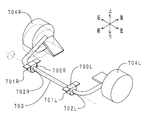
- Fig. 6 shows a schematic diagram of the vehicle suspension.
- a thin line indicates a state before turning, and a solid line indicates a state during turning.
- the stabilizer bushes 700L and 700R are fixed to a vehicle body (not shown) via brackets 701L and 701R.
- a stabilizer bar 703 is disposed in the holding holes 702L and 702R of the stabilizer bushes 700L and 700R.
- the stabilizer bar 703 is twisted counterclockwise as viewed from the left in the drawing. Using the elastic restoring force against the torsion, the stabilizer bar 703 suppresses the roll of the vehicle when turning.
- the stabilizer bar 703 When the stabilizer bar 703 is twisted or when the twisted stabilizer bar 703 is moved back by the elastic restoring force, the stabilizer bar 703 outer peripheral surface and the inner peripheral surfaces of the holding holes 702L and 702R slide relative to each other. If the frictional resistance at the time of sliding is large, there is a risk that abnormal noise (so-called stick-slip noise) will increase. In addition, the ride comfort of the vehicle may be deteriorated.
- abnormal noise so-called stick-slip noise
- a liner made of PTFE (polytetrafluoroethylene) having a small friction coefficient has been inserted into the holding holes 702L and 702R.
- the inner peripheral surface of the liner and the outer peripheral surface of the stabilizer bar 703 are brought into sliding contact.
- PTFE liners are relatively expensive. For this reason, when a PTFE liner is employed, the manufacturing cost of the stabilizer bushings 700L and 700R increases.
- Patent Literature 1 discloses a stabilizer bush having a rubber elastic body made of self-lubricating rubber.
- the rubber elastic body has a holding hole.
- a stabilizer bar is disposed in the holding hole. According to the stabilizer bush described in this document, the frictional resistance between the stabilizer bush and the stabilizer bar is reduced by causing the fatty acid amide, which is a component of the self-lubricating rubber, to ooze out from the inner peripheral surface of the holding hole.
- Patent Document 2 discloses a stabilizer bush including a rubber elastic body made of self-lubricating rubber and a lubricant.
- the rubber elastic body has a holding hole.
- a stabilizer bar is disposed in the holding hole.
- a grid-like rib is formed on the inner peripheral surface of the holding hole.
- the lubricant is held in a recess formed between the lattice-like ribs. Since the concave portion functions as a lubricant reservoir, the retention of the lubricant is enhanced.
- the lubricant can be continuously supplied smoothly between the stabilizer bush and the stabilizer bar. For this reason, the frictional resistance between the stabilizer bush and the stabilizer bar can be further reduced.
- paragraph [0026] of Patent Document 2 discloses a dry coat film containing particles having lubricity such as molybdenum particles as an example of a lubricant.
- Patent Document 2 does not specifically disclose a method for arranging the dry coat film on the inner peripheral surface of the holding hole.
- an object of the present invention is to provide a stabilizer bushing that has a small frictional resistance with the stabilizer bar outer peripheral surface and that prevents the coating from peeling off from the rubber elastic body.
- the stabilizer bush of the present invention is made of self-lubricating rubber containing an elastomer and a bleed lubricant, and has a holding hole for holding the stabilizer bar radially inward.
- a cylindrical rubber elastic body attached to the vehicle body by a bracket and an inner peripheral surface of the holding hole and containing a resin having a mercapto group can be deformed following the deformation of the rubber elastic body
- the bleeding lubricant of the rubber elastic body penetrates the coating and oozes out to the surface of the coating, and is formed on the surface of the coating, and relatively to the outer peripheral surface of the stabilizer bar.
- a lubricating film in sliding contact (corresponding to claim 1).
- the stabilizer bush of the present invention includes a rubber elastic body, a coating film, and a lubricating film.
- the lubricating film is in sliding contact with the stabilizer bar. Further, if there is a portion where the lubricating film is insufficient at the sliding interface between the stabilizer bush and the stabilizer bar, a coating containing a bleed lubricant is exposed from the portion and is in sliding contact with the stabilizer bar.
- the lubricating film mainly comes into sliding contact with the stabilizer bar preliminarily. Also, the rubber elastic body does not slide on the stabilizer bar. For this reason, the frictional resistance with the stabilizer bar is small.
- a mercapto group (—SH) is introduced into the resin forming the film.
- the mercapto group is a functional group having high reactivity with the elastomer.
- the inner peripheral surface of the holding hole should have a substantially smooth curved surface.
- the lubricant is held by the concave portions formed between the grid-like ribs.
- the bleed lubricant can be held by the permeable film.
- the recessed part indispensable to the stabilizer bush of patent document 2 is not essential in the case of the stabilizer bush of this invention (however, even if there exists a recessed part, it is contained in the structure of said (1)).
- the inner peripheral surface of the holding hole of this configuration has a substantially smooth curved surface shape (a curved surface shape without an artificial uneven shape). For this reason, it is not necessary to form a recessed part in the internal peripheral surface of a holding hole.
- the tops of the grid-like ribs come into sliding contact (line contact) with the stabilizer bar.
- the pressure applied from the stabilizer bar to the top of the rib is relatively high. For this reason, the top of the rib is easily worn. Therefore, the durability of the rubber elastic body is low.
- the inner peripheral surface of the holding hole of this configuration is not provided with an uneven shape.
- the inner peripheral surface is in surface contact with the stabilizer bar substantially entirely through the coating film and the lubricating film (in some cases, only the coating film). Therefore, the durability of the rubber elastic body is high.
- the coating film should further contain a solid lubricant (corresponding to claim 2).
- a solid lubricant corresponding to claim 2.
- the solid lubricant is preferably made of polytetrafluoroethylene (corresponding to claim 3).
- Polytetrafluoroethylene has a particularly low friction coefficient among solid lubricants. For this reason, according to this structure, the frictional resistance of the coating film itself with respect to the stabilizer bar is further reduced.
- the coating film should contain 200 parts by mass or less of the solid lubricant with respect to 100 parts by mass of the resin.
- the reason why the content of the solid lubricant is set to 200 parts by mass or less is that when it exceeds 200 parts by mass, the coating tends to be worn. That is, the durability of the coating is lowered.
- the coating film should contain 160 parts by mass or less of the solid lubricant. If it carries out like this, the frictional resistance of the film with respect to a stabilizer bar can be made small, ensuring the durability of a film.
- the coating film should contain 110 parts by mass or more and 130 parts by mass or less of the solid lubricant.
- the reason why the content of the solid lubricant is 110 parts by mass or more is that when it is less than 110 parts by mass, the frictional resistance of the coating against the stabilizer bar increases.
- the reason why the content of the solid lubricant is 130 parts by mass or less is that when the amount exceeds 130 parts by mass, the coating is likely to be worn. According to this configuration, the frictional resistance of the coating against the stabilizer bar can be further reduced while ensuring the durability of the coating.
- the resin is a silicone resin (corresponding to claim 5).
- the coating film is formed including the silicone resin.
- the bleed lubricant of the rubber elastic body is easy to permeate the coating. Therefore, the lubricating film can be reliably formed on at least a part of the surface of the coating.
- the film is formed including a silicone resin, the film is relatively flexible. Therefore, the coating is easily deformed following the deformation of the rubber elastic body.
- the silicone resin should have a configuration in which the cross-linked structure is sparser than the straight silicone resin and a modified product thereof and has rubber elasticity. Corresponding).
- straight silicone resin means a silicone resin containing only a methyl group and a silicone resin containing only a methylphenyl group.
- modified product of straight silicone resin include an epoxy-modified silicone resin, an alkyd-modified silicone resin, a polyester-modified silicone resin, a silica-modified silicone resin, and an acrylic-modified silicone resin.
- silicone resin having “rubber elasticity” include rubber composite silicone resins and rubber elastic silicone resins used for rubber-based coating agents and the like.
- the lubricating film can be more reliably formed on at least a part of the surface of the coating.
- the present invention it is possible to provide a stabilizer bushing that has a small frictional resistance with the stabilizer bar and that prevents the coating from peeling off from the rubber elastic body.
- FIG. 1 is a layout view of a stabilizer bush which is an embodiment of the stabilizer bush of the present invention.
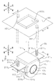
- FIG. 2 is a combined perspective view of the stabilizer bush and the bracket.
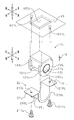
- FIG. 3 is an exploded perspective view of the stabilizer bush and the bracket. 4 is a sectional view taken along the line IV-IV in FIG.
- FIG. 5 is an enlarged view in the frame V of FIG.
- FIG. 6 is a schematic diagram of a vehicle suspension.
- FIG. 1 shows a layout view of the stabilizer bush of the present embodiment.
- members such as a suspension 90, a hub unit 91, a steering gear 92, and a drive shaft 93 are disposed near the front wheel of the vehicle 9.
- the suspension 90 includes springs 900L and 900R, shock absorbers 901L and 901R, lower suspension arms 902L and 902R, a stabilizer bar 903, and the like.
- the stabilizer bar 903 is made of steel and has a long-axis pipe shape that bulges forward in a C-shape.
- Both ends in the left-right direction of the stabilizer bar 903 are connected to the lower suspension arms 902L and 902R.
- the left and right two portions of the center portion of the stabilizer bar 903 are connected to the body (not shown) of the vehicle 9 via the stabilizer bushes 1L and 1R and the brackets 2L and 2R.
- the stabilizer bushes 1L and 1R are interposed between the stabilizer bar 903 and the body of the vehicle 9.
- the stabilizer bushes 1 ⁇ / b> L and 1 ⁇ / b> R suppress the vibration input from the front wheels from being transmitted to the body of the vehicle 9 via the stabilizer bar 903.
- the left and right stabilizer bushes 1L and 1R have the same configuration.
- the configuration of the left stabilizer bush 1L will be described, and the description will also serve as the description of the configuration of the right stabilizer bush 1R.
- FIG. 2 shows a combined perspective view of the stabilizer bush and the bracket of the present embodiment.
- FIG. 3 the disassembled perspective view of the stabilizer bush and bracket of this embodiment is shown.
- FIG. 4 shows a cross-sectional view in the IV-IV direction of FIG.
- the stabilizer bush 1L of the present embodiment includes a rubber elastic body 10L, a coating 11L, and a lubricating film 12L.
- the rubber elastic body 10L has a solid U shape when viewed from the left or right. That is, the upper part of the rubber elastic body 10L has a rectangular shape. The lower part of the rubber elastic body has a semicircular shape.
- the rubber elastic body 10L includes a holding hole 100L penetrating in the left-right direction.
- the inner peripheral surface of the holding hole 100L has a substantially smooth curved surface with a predetermined curvature. That is, artificial unevenness (for example, the lattice-like ribs of Patent Document 2) is not formed on the inner peripheral surface of the holding hole 100L.
- the outside of the rubber elastic body 10L and the inside of the holding hole 100L communicate with each other through the cutting portion 101L.
- a stabilizer bar 903 is disposed in the holding hole 100L.
- the stabilizer bar 903 is inserted into the holding hole 100L from the outside of the rubber elastic body 10L through an opening formed by opening the cutting portion 101L in the vertical direction.
- a pair of flange portions 104L are formed on the left and right edges of the rubber elastic body 10L.
- Each of the pair of flange portions 104L has a U-shape that opens upward.
- the coating 11L has a cylindrical shape.
- the coating 11L covers the inner peripheral surface of the holding hole 100L.
- the film thickness (radial thickness) of the coating 11L is about 20 ⁇ m.
- the lubricating film 12L is liquid and covers the surface (inner peripheral surface) of the coating 11L.
- the surface of the lubricating film 12L (the surface of the coating 11L when the lubricating film 12L is insufficient) is in contact with the outer peripheral surface of the stabilizer bar 903.
- FIG. 5 shows an enlarged view in the frame V of FIG.
- FIG. 5 is a schematic diagram for explaining the functions of the stabilizer bushes 1L and 1R of the present embodiment.
- Rubber elastic body 10L is made of self-lubricating rubber.
- the rubber elastic body 10L includes a blend rubber (hereinafter simply referred to as “blend rubber”) 102L of NR (natural rubber) and BR (butadiene rubber), and oleic acid amide 103L.
- blend rubber 102L is included in the elastomer of the present invention.
- Oleic acid amide 103L is included in the bleed lubricant of the present invention.
- the coating 11L (for example, manufactured by STTY Corporation “SOLVEST 398”) includes a silicone resin 110L having a mercapto group and a solid lubricant 111L made of PTFE.
- the solid lubricant 111L is included in an amount of 120 parts by mass with respect to 100 parts by mass of the silicone resin 110L.
- the solid lubricant 111L has a substantially spherical shape with a particle diameter (median diameter) of about 1 ⁇ m or less and an average particle diameter of about 0.5 ⁇ m.
- the lubricating film 12L is formed of oleic acid amide 103L of rubber elastic body 10L. That is, the oleic acid amide 103L of the rubber elastic body 10L passes through the coating 11L as indicated by the white arrow in FIG. And it oozes out on the surface of the coating 11L.
- the lubricating film 12L is formed by the oleic amide 103L that has oozed out.
- the stabilizer bar 903 is twisted around the axis according to the behavior of the vehicle 9.
- the stabilizer bush 1L is fixed to the body of the vehicle 9 via a bracket 2L described later.
- the surface of the lubricating film 12 ⁇ / b> L (the surface of the coating 11 ⁇ / b> L when the lubricating film 12 ⁇ / b> L is insufficient) is relatively in sliding contact with the outer peripheral surface of the stabilizer bar 903.
- bracket structure Next, the structure of the brackets 2L and 2R of this embodiment will be described.
- the structures of the left and right brackets 2L and 2R are the same.
- the structure of the left bracket 2L will be described, and the description will also serve as the description of the structure of the right bracket 2R.
- the bracket 2L of the present embodiment is made of steel and includes a bush holding portion 20L and a pair of fixing portions 21L.
- the bush holding portion 20L has a U shape that opens upward as viewed from the left or right.
- a pair of flange portions 200L are formed on both left and right edges of the bush holding portion 20L.
- a portion between the pair of flange portions 104L in the stabilizer bush 1L is accommodated inside the U-shaped opening of the bush holding portion 20L.
- the pair of flange portions 200L are in contact with the pair of flange portions 104L from the inner side in the left-right direction. By the contact, it is possible to suppress the stabilizer bush 1L from falling off from the bracket 2L in the left-right direction.
- Each of the pair of fixed portions 21L has a rectangular plate shape.
- the pair of fixing portions 21L are connected to both U-shaped ends of the bush holding portion 20L.
- Each of the pair of fixing portions 21L is formed with a bolt insertion hole 210L.
- Bolts 211L are respectively inserted from below into the pair of bolt insertion holes 210L.
- a concave portion 950L and a pair of bolt fastening holes 951L are disposed on the lower surface of the body 95 of the vehicle 9.
- the internal space of the recess 950L has a rectangular parallelepiped shape.
- the upper portion of the stabilizer bush 1L is inserted into the recess 950L.
- the pair of bolt fastening holes 951L are arranged in the front-rear direction of the recess 950L.
- the bolt 211L passes through the bolt insertion hole 210L and is screwed to the bolt fastening hole 951L.
- the bracket 2L is fixed to the lower surface of the body 95 by the pair of bolts 211L.
- the stabilizer bush 1L is sandwiched and fixed between the bracket 2L and the lower surface of the body 95.
- the rubber elastic body 10L is fixed, the upper portion of the rubber elastic body 10L is compressed and deformed by the tightening margin S (see FIGS. 2 and 3). Due to the tightening allowance S, the stabilizer bush 1L is in pressure contact with the outer peripheral surface of the stabilizer bar 903.
- the manufacturing method of the stabilizer bushes 1L and 1R of the present embodiment includes a composition preparation process, a crosslinking process, a degreasing process, a coating process, and a firing process.
- the composition preparation step the composition is prepared by kneading the raw material of the blend rubber 102L, oleic acid amide 103L, a crosslinking agent and the like.
- the composition is injected into the cavity of the mold that has been clamped, and the raw material of the blend rubber 102L in the cavity is subjected to a crosslinking reaction. Subsequently, the mold is opened, and the rubber elastic body 10L is collected from the cavity. Then, the cutting portion 101L (see FIG. 4) is formed in the rubber elastic body 10L. The oleic amide 103L oozes out from the inner peripheral surface of the holding hole 100L of the rubber elastic body 10L.
- the inner peripheral surface of the holding hole 100L of the rubber elastic body 10L is degreased with IPA (isopropyl alcohol). Then, the oleic amide 103L is removed from the inner peripheral surface of the holding hole 100L.
- IPA isopropyl alcohol
- paint is applied to the inner peripheral surface of the clean holding hole 100L.
- the paint contains a raw material of a silicone resin 110L having a mercapto group and a solid lubricant 111L made of PTFE.
- the rubber elastic body 10L coated with the paint is fired.
- the raw material of the silicone resin 110L having a mercapto group is thermally cured by firing.
- the coating 11L is formed on the inner peripheral surface of the holding hole 100L.
- the oleic acid amide 103L of the rubber elastic body 10L is transmitted through the formed coating 11L.
- a lubricating film 12L is formed on the surface of the coating 11L by the oleic acid amide 103L that has passed through the coating 11L. In this way, the stabilizer bush 1L of the present embodiment is manufactured.
- the lubricant films 12L of the stabilizer bushes 1L and 1R of the present embodiment are in sliding contact with the stabilizer bar 903.
- the coating 11L is displayed from the portion. And is in sliding contact with the stabilizer bar 903.
- the coating 11L containing the oleic acid amide 103L and the solid lubricant 111L is in sliding contact with the stabilizer bar 903.
- the lubricating film 12L is normally in sliding contact with the stabilizer bar 903.
- the coating 11L is in sliding contact with the stabilizer bar 903.
- the rubber elastic body 10L does not slide on the stabilizer bar 903. For this reason, the frictional resistance with the stabilizer bar 903 is small.
- a mercapto group (-SH) is introduced into the silicone resin 110L forming the coating 11L.
- the mercapto group is a functional group having high reactivity with the elastomer.
- the rubber elastic body 10L and the coating 11L can be firmly bonded (chemically bonded). Accordingly, the coating 11L is hardly peeled off from the rubber elastic body 10L. Further, the coating 11L easily deforms following the deformation of the rubber elastic body 10L.
- the solid lubricant 111L is made of PTFE having a particularly small friction coefficient. Also in this point, the coating 11L of the stabilizer bushes 1L and 1R of the present embodiment has a small frictional resistance with respect to the stabilizer bar 903.
- the solid lubricant 111L is included in an amount of 120 parts by mass with respect to 100 parts by mass of the silicone resin 110L. For this reason, the frictional resistance of the coating 11L with respect to the stabilizer bar 903 can be reduced while ensuring the durability of the coating 11L.
- the resin forming the coating 11L is the silicone resin 110L.
- the oleic amide 103L of the rubber elastic body 10L is likely to pass through the coating 11L. Therefore, the lubricating film 12L can be reliably formed on the surface of the coating 11L.
- the coating 11L is formed including the silicone resin 110L, the coating 11L is relatively flexible. Therefore, also in this respect, the coating 11L is easily deformed following the deformation of the rubber elastic body 10L.
- the silicone resin 110L for forming the coating 11L (for example, manufactured by STTY Corporation “SOLVEST 398”) is a rubber elastic silicone resin.
- the silicone resin 110L has a looser cross-linked structure than the straight silicone resin and its modified product, and has rubber elasticity. For this reason, the oleic acid amide 103L of the rubber elastic body 10L is more easily transmitted through the coating 11L. Therefore, the lubricating film 12L can be formed more reliably.
- the oleic acid amide 103L can be held by the permeable coating 11L. For this reason, unlike the stabilizer bush of the above-mentioned patent document 2, it is not necessary to form the recessed part for holding oleic amide 103L in the rubber elastic body 10L.
- the interface between the rubber elastic body 10L and the coating 11L has a microscopic uneven shape. That is, the rubber elastic body 10L and the coating 11L bite into each other at the interface. For this reason, the rubber elastic body 10L and the coating 11L can be firmly joined by the so-called “anchor effect”.
- the material of the elastomer of the rubber elastic body 10L is not particularly limited.
- NR, BR, IR isoprene rubber
- SBR styrene butadiene rubber
- CR chloroprene rubber
- NBR nitrile rubber
- EPDM ethylene propylene rubber
- IIR butyl rubber
- ACM acrylic rubber
- U Urethane rubber
- silicone rubber or a blended material thereof can be used.
- the material of the bleed lubricant for the rubber elastic body 10L is not particularly limited.
- fatty acid amides unsaturated fatty acid amides (oleic acid amide, erucic acid amide, etc.), saturated fatty acid amides (stearic acid amide, behenic acid amide, etc.)
- silicone oil polyethylene glycol type surfactants and the like can be used.
- the resin material of the coating 11L is not particularly limited.
- polyester, acrylic, urethane or the like can be used.
- the material of the solid lubricant 111L of the coating 11L is not particularly limited.
- graphite, molybdenum disulfide, fluorine resin, or the like can be used.
- fluororesin include PFA (tetrafluoroethylene / perfluoroalkoxy vinyl ether copolymer), FEP (tetrafluoroethylene / hexafluoropropylene copolymer), PCTFE (polychlorotrifluoroethylene), ETFE (tetrafluoro).
- Ethylene / ethylene copolymer Ethylene / ethylene copolymer
- ECTFE chlorotrifluoroethylene / ethylene copolymer
- PVDF polyvinylidene fluoride
- PVF polyvinyl fluoride
- sample The sample used for the test is one in which the content of the solid lubricant 111L of the coating 11L is set to four levels in the stabilizer bush 1L (see FIGS. 2 to 5) of the above embodiment.
- Example 1 in which the content of the solid lubricant 111L was 0 parts by mass with respect to 100 parts by mass of the silicone resin 110L. Further, Example 2 was used in which the content of the solid lubricant 111L was 120 parts by mass (that is, the stabilizer bush 1L itself in the above embodiment) with respect to 100 parts by mass of the silicone resin 110L. Moreover, what made content of the solid lubricant 111L 160 mass parts with respect to silicone resin 110L100 mass parts was set as Example 3. FIG. Moreover, what made content of the solid lubricant 111L 200 mass parts with respect to 100 mass parts of silicone resins 110L was set as Example 4. Further, a sample having only the rubber elastic body 10L (without the coating 11L and the lubricating film 12L) was used as a comparative example.
- each sample was fixed to a jig (corresponding to the lower surface of the body 95 of the vehicle 9 of the above embodiment) by the bracket 2L.
- a shaft (corresponding to the stabilizer bar 903 in the above embodiment) was inserted through the holding hole 100L of each sample. Then, using a torque wrench, the shaft was twisted ⁇ 15 ° around the axis. Then, the torsion torque applied to the shaft was measured.
- the frictional resistance between the shaft and the sample is small, the torsional torque applied to the shaft is small.
- the frictional resistance between the shaft and the sample is large, the torsional torque applied to the shaft increases.
- 1L Stabilizer bush
- 1R Stabilizer bush
- 2L Bracket
- 2R Bracket
- 9 Vehicle.
- 10L rubber elastic body
- 11L coating film
- 12L lubricating film
- 20L bush holding section
- 21L fixing section
- 90 suspension
- 91 hub unit
- 92 steering gear
- 93 drive shaft
Landscapes
- Engineering & Computer Science (AREA)
- General Engineering & Computer Science (AREA)
- Mechanical Engineering (AREA)
- Springs (AREA)
- Vehicle Body Suspensions (AREA)
- Vibration Prevention Devices (AREA)
Abstract
Description
まず、本実施形態のスタビライザブッシュの配置について説明する。図1に、本実施形態のスタビライザブッシュの配置図を示す。図1に示すように、車両9の前輪付近には、サスペンション90、ハブユニット91、ステアリングギヤ92、ドライブシャフト93などの部材が配置されている。サスペンション90は、スプリング900L、900R、ショックアブソーバ901L、901R、ロアサスペンションアーム902L、902R、スタビライザバー903などを備えている。スタビライザバー903は、鋼製であって、前方にC字状に膨出する長軸パイプ状を呈している。スタビライザバー903の左右方向両端は、ロアサスペンションアーム902L、902Rに連結されている。スタビライザバー903の中央部分の左右二箇所は、スタビライザブッシュ1L、1R、ブラケット2L、2Rを介して、車両9のボディ(図略)に連結されている。このように、スタビライザブッシュ1L、1Rは、スタビライザバー903と、車両9のボディと、の間に介装されている。スタビライザブッシュ1L、1Rは、前輪から入力される振動が、スタビライザバー903を介して、車両9のボディに伝達されるのを抑制している。
次に、本実施形態のスタビライザブッシュ1L、1Rの構造について説明する。左右二つのスタビライザブッシュ1L、1Rの構成は同じである。以下、左側のスタビライザブッシュ1Lの構成について説明し、当該説明をもって右側のスタビライザブッシュ1Rの構成についての説明を兼ねるものとする。
次に、本実施形態のスタビライザブッシュ1L、1Rの材質について説明する。図5に、図4の枠V内の拡大図を示す。なお、図5は、本実施形態のスタビライザブッシュ1L、1Rの機能を説明するための、模式図である。
次に、本実施形態のブラケット2L、2Rの構造について説明する。左右二つのブラケット2L、2Rの構造は同じである。以下、左側のブラケット2Lの構造について説明し、当該説明をもって右側のブラケット2Rの構造についての説明を兼ねるものとする。図2~図4に示すように、本実施形態のブラケット2Lは、鋼製であって、ブッシュ保持部20Lと、一対の固定部21Lと、を備えている。
次に、本実施形態のスタビライザブッシュ1L、1Rの製造方法について説明する。左右二つのスタビライザブッシュ1L、1Rの製造方法は同じである。以下、左側のスタビライザブッシュ1Lの製造方法について説明し、当該説明をもって右側のスタビライザブッシュ1Rの製造方法についての説明を兼ねるものとする。
次に、本実施形態のスタビライザブッシュ1L、1Rの作用効果について説明する。本実施形態のスタビライザブッシュ1L、1Rの潤滑膜12Lは、スタビライザバー903に摺接する。また、例えば潤滑膜12Lの一時的な膜切れなどにより、潤滑膜12Lが不足する部分がスタビライザブッシュ1L、1Rとスタビライザバー903との摺動界面にある場合には、当該部分から被膜11Lが表出し、スタビライザバー903に摺接する。すなわち、潤滑膜12Lが不足する場合であっても、オレイン酸アミド103Lおよび固体潤滑剤111Lを含有する被膜11Lが、スタビライザバー903に摺接する。このように、本実施形態のスタビライザブッシュ1L、1Rによると、通常は、潤滑膜12Lがスタビライザバー903に摺接する。また、潤滑膜12Lが不足する場合は、被膜11Lがスタビライザバー903に摺接する。また、ゴム弾性体10Lがスタビライザバー903に摺接しない。このため、スタビライザバー903との間の摩擦抵抗が小さい。
以上、本発明のスタビライザブッシュの実施の形態について説明した。しかしながら、実施の形態は上記形態に特に限定されるものではない。当業者が行いうる種々の変形的形態、改良的形態で実施することも可能である。
試験に用いるサンプルは、上記実施形態のスタビライザブッシュ1L(図2~図5参照)において、被膜11Lの固体潤滑剤111Lの含有量を、4水準設定したものである。
まず、各サンプルを、ブラケット2Lにより、ジグ(上記実施形態の車両9のボディ95の下面に相当)に固定した。次いで、各サンプルの保持孔100Lに、シャフト(上記実施形態のスタビライザバー903に相当)を、挿通した。それから、トルクレンチを用いて、シャフトを軸周りに±15°だけ捩った。そして、シャフトに加わる捩りトルクを測定した。シャフトとサンプルとの間の摩擦抵抗が小さい場合、シャフトに加わる捩りトルクは小さくなる。反対に、シャフトとサンプルとの間の摩擦抵抗が大きい場合、シャフトに加わる捩りトルクは大きくなる。
比較例の捩りトルクを100%とした場合、実施例1の捩りトルクは23%だった。また、実施例2の捩りトルクは25%だった。また、実施例3の捩りトルクは42%だった。また、実施例4の捩りトルクは55%だった。このように、実施例1~実施例4の方が、比較例よりも捩りトルクが小さいことが判った。すなわち、実施例1~実施例4の方が、比較例よりも、サンプルとシャフトとの間の摩擦抵抗が小さいことが判った。
10L:ゴム弾性体、11L:被膜、12L:潤滑膜、20L:ブッシュ保持部、21L:固定部、90:サスペンション、91:ハブユニット、92:ステアリングギヤ、93:ドライブシャフト、95:ボディ。
100L:保持孔、101L:切断部、102L:ブレンドゴム(エラストマー)、103L:オレイン酸アミド(ブリード性潤滑剤)、104L:フランジ部、110L:シリコーン樹脂、111L:固体潤滑剤、200L:フランジ部、210L:ボルト挿通孔、211L:ボルト、900L:スプリング、900R:スプリング、901L:ショックアブソーバ、901R:ショックアブソーバ、902L:ロアサスペンションアーム、902R:ロアサスペンションアーム、903:スタビライザバー、950L:凹部、951L:ボルト止着孔。
S:締め代。
Claims (6)
- エラストマーと、ブリード性潤滑剤と、を含有する自己潤滑ゴム製であって、径方向内側にスタビライザバーを保持する保持孔を有すると共に、ブラケットにより車両のボディに取り付けられる筒状のゴム弾性体と、
該保持孔の内周面を覆うと共に、メルカプト基を持つ樹脂を含有し、該ゴム弾性体の変形に追従して変形可能な被膜と、
該ゴム弾性体の該ブリード性潤滑剤が該被膜を透過して該被膜の表面に滲み出ることにより該被膜の表面に形成されると共に、該スタビライザバーの外周面に相対的に摺接する潤滑膜と、
を備えてなるスタビライザブッシュ。 - 前記被膜は、さらに、固体潤滑剤を含有する請求項1に記載のスタビライザブッシュ。
- 前記固体潤滑剤は、ポリテトラフルオロエチレン製である請求項2に記載のスタビライザブッシュ。
- 前記被膜は、前記固体潤滑剤を、前記樹脂100質量部に対して、200質量部以下含有する請求項3に記載のスタビライザブッシュ。
- 前記樹脂は、シリコーン樹脂である請求項1ないし請求項4のいずれかに記載のスタビライザブッシュ。
- 前記シリコーン樹脂は、ストレートシリコーン樹脂およびその変性物よりも架橋構造が疎であって、ゴム弾性を有する請求項5に記載のスタビライザブッシュ。
Priority Applications (4)
| Application Number | Priority Date | Filing Date | Title |
|---|---|---|---|
| JP2010531863A JP4842401B2 (ja) | 2008-09-30 | 2009-09-29 | スタビライザブッシュ |
| DE112009002005.4T DE112009002005B4 (de) | 2008-09-30 | 2009-09-29 | Stabilisatorbuchse |
| CN200980138728.8A CN102171483B (zh) | 2008-09-30 | 2009-09-29 | 稳定器衬套 |
| US13/054,280 US20110170814A1 (en) | 2008-09-30 | 2009-09-29 | Stabilizer bushing |
Applications Claiming Priority (2)
| Application Number | Priority Date | Filing Date | Title |
|---|---|---|---|
| JP2008254950 | 2008-09-30 | ||
| JP2008-254950 | 2008-09-30 |
Publications (1)
| Publication Number | Publication Date |
|---|---|
| WO2010038749A1 true WO2010038749A1 (ja) | 2010-04-08 |
Family
ID=42073510
Family Applications (1)
| Application Number | Title | Priority Date | Filing Date |
|---|---|---|---|
| PCT/JP2009/066968 Ceased WO2010038749A1 (ja) | 2008-09-30 | 2009-09-29 | スタビライザブッシュ |
Country Status (5)
| Country | Link |
|---|---|
| US (1) | US20110170814A1 (ja) |
| JP (1) | JP4842401B2 (ja) |
| CN (1) | CN102171483B (ja) |
| DE (1) | DE112009002005B4 (ja) |
| WO (1) | WO2010038749A1 (ja) |
Cited By (3)
| Publication number | Priority date | Publication date | Assignee | Title |
|---|---|---|---|---|
| CN102941790A (zh) * | 2012-10-23 | 2013-02-27 | 安徽誉丰汽车技术有限责任公司 | 一种机动车稳定杆衬套结构 |
| WO2014045887A1 (ja) * | 2012-09-21 | 2014-03-27 | 東海ゴム工業株式会社 | 防振ゴム部材およびその製造方法 |
| US9033320B2 (en) | 2011-06-30 | 2015-05-19 | Sumitomo Riko Company Limited | Anti-vibration rubber member and production method thereof |
Families Citing this family (12)
| Publication number | Priority date | Publication date | Assignee | Title |
|---|---|---|---|---|
| JP5748318B2 (ja) * | 2008-07-18 | 2015-07-15 | 日本発條株式会社 | スタビライザー装置 |
| JP5093411B2 (ja) * | 2010-07-23 | 2012-12-12 | 新日本製鐵株式会社 | 樹脂モールドされる積層鉄芯に使用される電磁鋼板及びその製造方法 |
| WO2013121674A1 (ja) * | 2012-02-15 | 2013-08-22 | 本田技研工業株式会社 | ブッシュ |
| KR20150039548A (ko) * | 2013-10-02 | 2015-04-10 | 가부시키가이샤 시마노 | 접동 부재, 접동 부재를 이용한 자전거용 부품, 접동 부재를 이용한 낚시구용 부품, 및 접동 부재의 제조 방법 |
| JP6276383B2 (ja) * | 2014-03-25 | 2018-02-07 | 株式会社ヨロズ | 巻きカラー、巻きカラーの製造装置、および巻きカラーの製造方法 |
| JP6347226B2 (ja) | 2015-04-16 | 2018-06-27 | トヨタ自動車株式会社 | スタビライザバー取付装置、スタビライザバー取付用ブラケット |
| US9931902B2 (en) * | 2015-04-16 | 2018-04-03 | Toyota Jidosha Kabushiki Kaisha | Stabilizer bushing and stabilizer-bar mounting device |
| CN105235469A (zh) * | 2015-10-28 | 2016-01-13 | 宁国九鼎橡塑制品有限公司 | 一种汽车用横向稳定杆衬套 |
| JP6797922B2 (ja) * | 2016-08-03 | 2020-12-09 | 日本発條株式会社 | 車両用ばねの製造方法 |
| JP6585641B2 (ja) | 2017-01-27 | 2019-10-02 | 住友理工株式会社 | 防振ゴム組成物および防振ゴム部材 |
| CN109094323B (zh) * | 2018-08-16 | 2021-08-20 | 安徽奥丰汽车配件有限公司 | 一种汽车底盘自润滑稳定杆衬套橡胶组件 |
| JP7284647B2 (ja) * | 2019-06-20 | 2023-05-31 | Toyo Tire株式会社 | スタビライザブッシュ |
Citations (4)
| Publication number | Priority date | Publication date | Assignee | Title |
|---|---|---|---|---|
| JPH02132127A (ja) * | 1988-11-11 | 1990-05-21 | Nippon Sheet Glass Co Ltd | 摩擦低減膜 |
| JPH02286929A (ja) * | 1989-04-20 | 1990-11-27 | Pullman Co | サスペンションリンク支持ブッシュ |
| JP2001165237A (ja) * | 1999-12-07 | 2001-06-19 | Ntn Corp | 滑り支承 |
| JP2006273181A (ja) * | 2005-03-30 | 2006-10-12 | Tokai Rubber Ind Ltd | 車両用スタビライザブッシュ |
Family Cites Families (17)
| Publication number | Priority date | Publication date | Assignee | Title |
|---|---|---|---|---|
| US2946094A (en) * | 1956-06-11 | 1960-07-26 | Kawasaki Sozo | Process of making oil-impregnated machine parts from synthetic resin and the articles manufactured by said process |
| US2989657A (en) * | 1956-07-23 | 1961-06-20 | Westinghouse Electric Corp | Laminated structure having polyfluoroethylene on one surface thereof |
| DE3174449D1 (en) * | 1981-03-02 | 1986-05-28 | Chromex Sa | Self-lubricating elastic bearing |
| JPS6357310A (ja) * | 1986-08-27 | 1988-03-12 | Toyoda Gosei Co Ltd | 車両用スタビライザブツシユ |
| JPS6357311A (ja) * | 1986-08-27 | 1988-03-12 | Toyoda Gosei Co Ltd | 車両用スタビライザブツシユ |
| US4880318A (en) * | 1987-01-21 | 1989-11-14 | Tokai Rubber Industries, Ltd. | Slidable vibration-isolating rubber member |
| JP3047501B2 (ja) * | 1991-04-15 | 2000-05-29 | 豊田合成株式会社 | 筒状防振ブッシュ |
| US5224790A (en) * | 1992-01-07 | 1993-07-06 | Gencorp Inc. | Stabilizer bar slip bushing with axial restraint |
| JP2878522B2 (ja) | 1992-03-16 | 1999-04-05 | 丸五ゴム工業株式会社 | 自動車部品用ゴムブッシュ |
| CN1072333C (zh) * | 1995-07-14 | 2001-10-03 | 株式会社Ntn | 轴承装置 |
| US5984283A (en) * | 1996-03-29 | 1999-11-16 | Toyoda Gosei Co., Ltd. | Vibration-damping rubber in suspension of vehicle |
| US6245836B1 (en) * | 1998-04-22 | 2001-06-12 | Oiles Corporation | Lubricating coating compound, sliding structure combining two sliding members in which lubricating coating compound is applied to one of the sliding members, and slide bearing apparatus using the same |
| US6474631B2 (en) * | 2000-03-16 | 2002-11-05 | Toyo Tire & Rubber Co., Ltd. | Stabilizer bushing |
| KR100674462B1 (ko) * | 2000-04-14 | 2007-01-30 | 세키스이가가쿠 고교가부시키가이샤 | 제진재용 수지 조성물, 제진재 및 차음 부재 |
| JP2003214431A (ja) * | 2002-01-23 | 2003-07-30 | Daido Metal Co Ltd | 摺動部材及びその製造方法 |
| JP4560376B2 (ja) * | 2004-10-29 | 2010-10-13 | 東海ゴム工業株式会社 | スタビライザブッシュ |
| CN2853477Y (zh) * | 2005-11-18 | 2007-01-03 | 重庆长安汽车股份有限公司 | 汽车前稳定杆衬套 |
-
2009
- 2009-09-29 CN CN200980138728.8A patent/CN102171483B/zh active Active
- 2009-09-29 WO PCT/JP2009/066968 patent/WO2010038749A1/ja not_active Ceased
- 2009-09-29 JP JP2010531863A patent/JP4842401B2/ja active Active
- 2009-09-29 DE DE112009002005.4T patent/DE112009002005B4/de active Active
- 2009-09-29 US US13/054,280 patent/US20110170814A1/en not_active Abandoned
Patent Citations (4)
| Publication number | Priority date | Publication date | Assignee | Title |
|---|---|---|---|---|
| JPH02132127A (ja) * | 1988-11-11 | 1990-05-21 | Nippon Sheet Glass Co Ltd | 摩擦低減膜 |
| JPH02286929A (ja) * | 1989-04-20 | 1990-11-27 | Pullman Co | サスペンションリンク支持ブッシュ |
| JP2001165237A (ja) * | 1999-12-07 | 2001-06-19 | Ntn Corp | 滑り支承 |
| JP2006273181A (ja) * | 2005-03-30 | 2006-10-12 | Tokai Rubber Ind Ltd | 車両用スタビライザブッシュ |
Cited By (4)
| Publication number | Priority date | Publication date | Assignee | Title |
|---|---|---|---|---|
| US9033320B2 (en) | 2011-06-30 | 2015-05-19 | Sumitomo Riko Company Limited | Anti-vibration rubber member and production method thereof |
| WO2014045887A1 (ja) * | 2012-09-21 | 2014-03-27 | 東海ゴム工業株式会社 | 防振ゴム部材およびその製造方法 |
| US9677636B2 (en) | 2012-09-21 | 2017-06-13 | Sumitomo Riko Company Limited | Anti-vibration rubber member and production method thereof |
| CN102941790A (zh) * | 2012-10-23 | 2013-02-27 | 安徽誉丰汽车技术有限责任公司 | 一种机动车稳定杆衬套结构 |
Also Published As
| Publication number | Publication date |
|---|---|
| CN102171483B (zh) | 2013-06-05 |
| DE112009002005B4 (de) | 2016-03-17 |
| CN102171483A (zh) | 2011-08-31 |
| JP4842401B2 (ja) | 2011-12-21 |
| DE112009002005T5 (de) | 2012-02-09 |
| JPWO2010038749A1 (ja) | 2012-03-01 |
| US20110170814A1 (en) | 2011-07-14 |
Similar Documents
| Publication | Publication Date | Title |
|---|---|---|
| JP4842401B2 (ja) | スタビライザブッシュ | |
| JP4792539B2 (ja) | 防振ゴム部材およびその製造方法 | |
| JP5780639B2 (ja) | 防振ゴム部材およびその製造方法 | |
| JP4560376B2 (ja) | スタビライザブッシュ | |
| US9677636B2 (en) | Anti-vibration rubber member and production method thereof | |
| MX2011003369A (es) | Material compuesto para cojinete de lisos amortiguador de vibraciones, buje de cojinete liso y cojinete liso completo. | |
| US10422372B2 (en) | Rotatable bushing | |
| WO2008143801A1 (en) | Bushing having self-lubricating overmold | |
| JP5302868B2 (ja) | 防振ブッシュ付きスタビライザバー及びその製造方法 | |
| JPH1151099A (ja) | ゴムブッシュ | |
| JP6731318B2 (ja) | スタビライザブッシュ付きスタビライザバーの製造方法とスタビライザブッシュの接着用治具、スタビライザバーのスタビライザブッシュ接着品 | |
| KR102771527B1 (ko) | 차량용 스테빌라이저바의 부시 장치 | |
| JP2008168756A (ja) | 防振ブッシュ付スタビライザバー及びその製造方法 | |
| JP2024154354A (ja) | 防振構造、ストラットマウント、及び、防振構造の製造方法 | |
| JP4131975B2 (ja) | 防振装置の取付構造 | |
| JPH11210794A (ja) | ゴムブッシュ | |
| JP2015121295A (ja) | トルクロッド | |
| JPH11117974A (ja) | ゴムブッシュ | |
| JP2006183768A (ja) | 防振装置の取付構造 | |
| JP2013167307A (ja) | ブッシュ | |
| JPH0512779U (ja) | ブツシユ | |
| JP2007261437A (ja) | スタビライザブッシュ | |
| JP2003065387A (ja) | 筒形防振支持体 | |
| MX2007013888A (en) | Heat shrunken low-friction stabilizer bar sleeve |
Legal Events
| Date | Code | Title | Description |
|---|---|---|---|
| WWE | Wipo information: entry into national phase |
Ref document number: 200980138728.8 Country of ref document: CN |
|
| 121 | Ep: the epo has been informed by wipo that ep was designated in this application |
Ref document number: 09817781 Country of ref document: EP Kind code of ref document: A1 |
|
| WWE | Wipo information: entry into national phase |
Ref document number: 2010531863 Country of ref document: JP |
|
| WWE | Wipo information: entry into national phase |
Ref document number: 13054280 Country of ref document: US |
|
| 122 | Ep: pct application non-entry in european phase |
Ref document number: 09817781 Country of ref document: EP Kind code of ref document: A1 |