WO2009125657A1 - 車輪用軸受装置 - Google Patents
車輪用軸受装置 Download PDFInfo
- Publication number
- WO2009125657A1 WO2009125657A1 PCT/JP2009/055138 JP2009055138W WO2009125657A1 WO 2009125657 A1 WO2009125657 A1 WO 2009125657A1 JP 2009055138 W JP2009055138 W JP 2009055138W WO 2009125657 A1 WO2009125657 A1 WO 2009125657A1
- Authority
- WO
- WIPO (PCT)
- Prior art keywords
- convex
- shaft
- fitting
- hole
- wheel
- Prior art date
Links
Images


Classifications
-
- B—PERFORMING OPERATIONS; TRANSPORTING
- B60—VEHICLES IN GENERAL
- B60B—VEHICLE WHEELS; CASTORS; AXLES FOR WHEELS OR CASTORS; INCREASING WHEEL ADHESION
- B60B27/00—Hubs
- B60B27/0005—Hubs with ball bearings
-
- B—PERFORMING OPERATIONS; TRANSPORTING
- B60—VEHICLES IN GENERAL
- B60B—VEHICLE WHEELS; CASTORS; AXLES FOR WHEELS OR CASTORS; INCREASING WHEEL ADHESION
- B60B27/00—Hubs
- B60B27/0015—Hubs for driven wheels
-
- B—PERFORMING OPERATIONS; TRANSPORTING
- B60—VEHICLES IN GENERAL
- B60B—VEHICLE WHEELS; CASTORS; AXLES FOR WHEELS OR CASTORS; INCREASING WHEEL ADHESION
- B60B27/00—Hubs
- B60B27/0015—Hubs for driven wheels
- B60B27/0021—Hubs for driven wheels characterised by torque transmission means from drive axle
- B60B27/0026—Hubs for driven wheels characterised by torque transmission means from drive axle of the radial type, e.g. splined key
-
- B—PERFORMING OPERATIONS; TRANSPORTING
- B60—VEHICLES IN GENERAL
- B60B—VEHICLE WHEELS; CASTORS; AXLES FOR WHEELS OR CASTORS; INCREASING WHEEL ADHESION
- B60B27/00—Hubs
- B60B27/0015—Hubs for driven wheels
- B60B27/0036—Hubs for driven wheels comprising homokinetic joints
- B60B27/0042—Hubs for driven wheels comprising homokinetic joints characterised by the fixation of the homokinetic joint to the hub
-
- B—PERFORMING OPERATIONS; TRANSPORTING
- B60—VEHICLES IN GENERAL
- B60B—VEHICLE WHEELS; CASTORS; AXLES FOR WHEELS OR CASTORS; INCREASING WHEEL ADHESION
- B60B27/00—Hubs
- B60B27/0078—Hubs characterised by the fixation of bearings
-
- B—PERFORMING OPERATIONS; TRANSPORTING
- B60—VEHICLES IN GENERAL
- B60B—VEHICLE WHEELS; CASTORS; AXLES FOR WHEELS OR CASTORS; INCREASING WHEEL ADHESION
- B60B27/00—Hubs
- B60B27/0078—Hubs characterised by the fixation of bearings
- B60B27/0084—Hubs characterised by the fixation of bearings caulking to fix inner race
-
- B—PERFORMING OPERATIONS; TRANSPORTING
- B60—VEHICLES IN GENERAL
- B60B—VEHICLE WHEELS; CASTORS; AXLES FOR WHEELS OR CASTORS; INCREASING WHEEL ADHESION
- B60B27/00—Hubs
- B60B27/0094—Hubs one or more of the bearing races are formed by the hub
-
- B—PERFORMING OPERATIONS; TRANSPORTING
- B60—VEHICLES IN GENERAL
- B60B—VEHICLE WHEELS; CASTORS; AXLES FOR WHEELS OR CASTORS; INCREASING WHEEL ADHESION
- B60B35/00—Axle units; Parts thereof ; Arrangements for lubrication of axles
- B60B35/12—Torque-transmitting axles
- B60B35/18—Arrangement of bearings
-
- F—MECHANICAL ENGINEERING; LIGHTING; HEATING; WEAPONS; BLASTING
- F16—ENGINEERING ELEMENTS AND UNITS; GENERAL MEASURES FOR PRODUCING AND MAINTAINING EFFECTIVE FUNCTIONING OF MACHINES OR INSTALLATIONS; THERMAL INSULATION IN GENERAL
- F16C—SHAFTS; FLEXIBLE SHAFTS; ELEMENTS OR CRANKSHAFT MECHANISMS; ROTARY BODIES OTHER THAN GEARING ELEMENTS; BEARINGS
- F16C19/00—Bearings with rolling contact, for exclusively rotary movement
- F16C19/02—Bearings with rolling contact, for exclusively rotary movement with bearing balls essentially of the same size in one or more circular rows
- F16C19/14—Bearings with rolling contact, for exclusively rotary movement with bearing balls essentially of the same size in one or more circular rows for both radial and axial load
- F16C19/18—Bearings with rolling contact, for exclusively rotary movement with bearing balls essentially of the same size in one or more circular rows for both radial and axial load with two or more rows of balls
- F16C19/181—Bearings with rolling contact, for exclusively rotary movement with bearing balls essentially of the same size in one or more circular rows for both radial and axial load with two or more rows of balls with angular contact
- F16C19/183—Bearings with rolling contact, for exclusively rotary movement with bearing balls essentially of the same size in one or more circular rows for both radial and axial load with two or more rows of balls with angular contact with two rows at opposite angles
- F16C19/184—Bearings with rolling contact, for exclusively rotary movement with bearing balls essentially of the same size in one or more circular rows for both radial and axial load with two or more rows of balls with angular contact with two rows at opposite angles in O-arrangement
- F16C19/186—Bearings with rolling contact, for exclusively rotary movement with bearing balls essentially of the same size in one or more circular rows for both radial and axial load with two or more rows of balls with angular contact with two rows at opposite angles in O-arrangement with three raceways provided integrally on parts other than race rings, e.g. third generation hubs
-
- F—MECHANICAL ENGINEERING; LIGHTING; HEATING; WEAPONS; BLASTING
- F16—ENGINEERING ELEMENTS AND UNITS; GENERAL MEASURES FOR PRODUCING AND MAINTAINING EFFECTIVE FUNCTIONING OF MACHINES OR INSTALLATIONS; THERMAL INSULATION IN GENERAL
- F16C—SHAFTS; FLEXIBLE SHAFTS; ELEMENTS OR CRANKSHAFT MECHANISMS; ROTARY BODIES OTHER THAN GEARING ELEMENTS; BEARINGS
- F16C35/00—Rigid support of bearing units; Housings, e.g. caps, covers
- F16C35/04—Rigid support of bearing units; Housings, e.g. caps, covers in the case of ball or roller bearings
- F16C35/06—Mounting or dismounting of ball or roller bearings; Fixing them onto shaft or in housing
- F16C35/062—Dismounting of ball or roller bearings
-
- F—MECHANICAL ENGINEERING; LIGHTING; HEATING; WEAPONS; BLASTING
- F16—ENGINEERING ELEMENTS AND UNITS; GENERAL MEASURES FOR PRODUCING AND MAINTAINING EFFECTIVE FUNCTIONING OF MACHINES OR INSTALLATIONS; THERMAL INSULATION IN GENERAL
- F16C—SHAFTS; FLEXIBLE SHAFTS; ELEMENTS OR CRANKSHAFT MECHANISMS; ROTARY BODIES OTHER THAN GEARING ELEMENTS; BEARINGS
- F16C35/00—Rigid support of bearing units; Housings, e.g. caps, covers
- F16C35/04—Rigid support of bearing units; Housings, e.g. caps, covers in the case of ball or roller bearings
- F16C35/06—Mounting or dismounting of ball or roller bearings; Fixing them onto shaft or in housing
- F16C35/063—Fixing them on the shaft
- F16C35/0635—Fixing them on the shaft the bore of the inner ring being of special non-cylindrical shape which co-operates with a complementary shape on the shaft, e.g. teeth, polygonal sections
-
- F—MECHANICAL ENGINEERING; LIGHTING; HEATING; WEAPONS; BLASTING
- F16—ENGINEERING ELEMENTS AND UNITS; GENERAL MEASURES FOR PRODUCING AND MAINTAINING EFFECTIVE FUNCTIONING OF MACHINES OR INSTALLATIONS; THERMAL INSULATION IN GENERAL
- F16C—SHAFTS; FLEXIBLE SHAFTS; ELEMENTS OR CRANKSHAFT MECHANISMS; ROTARY BODIES OTHER THAN GEARING ELEMENTS; BEARINGS
- F16C43/00—Assembling bearings
- F16C43/04—Assembling rolling-contact bearings
-
- F—MECHANICAL ENGINEERING; LIGHTING; HEATING; WEAPONS; BLASTING
- F16—ENGINEERING ELEMENTS AND UNITS; GENERAL MEASURES FOR PRODUCING AND MAINTAINING EFFECTIVE FUNCTIONING OF MACHINES OR INSTALLATIONS; THERMAL INSULATION IN GENERAL
- F16D—COUPLINGS FOR TRANSMITTING ROTATION; CLUTCHES; BRAKES
- F16D1/00—Couplings for rigidly connecting two coaxial shafts or other movable machine elements
- F16D1/06—Couplings for rigidly connecting two coaxial shafts or other movable machine elements for attachment of a member on a shaft or on a shaft-end
- F16D1/064—Couplings for rigidly connecting two coaxial shafts or other movable machine elements for attachment of a member on a shaft or on a shaft-end non-disconnectable
- F16D1/072—Couplings for rigidly connecting two coaxial shafts or other movable machine elements for attachment of a member on a shaft or on a shaft-end non-disconnectable involving plastic deformation
-
- F—MECHANICAL ENGINEERING; LIGHTING; HEATING; WEAPONS; BLASTING
- F16—ENGINEERING ELEMENTS AND UNITS; GENERAL MEASURES FOR PRODUCING AND MAINTAINING EFFECTIVE FUNCTIONING OF MACHINES OR INSTALLATIONS; THERMAL INSULATION IN GENERAL
- F16D—COUPLINGS FOR TRANSMITTING ROTATION; CLUTCHES; BRAKES
- F16D1/00—Couplings for rigidly connecting two coaxial shafts or other movable machine elements
- F16D1/10—Quick-acting couplings in which the parts are connected by simply bringing them together axially
- F16D1/108—Quick-acting couplings in which the parts are connected by simply bringing them together axially having retaining means rotating with the coupling and acting by interengaging parts, i.e. positive coupling
-
- F—MECHANICAL ENGINEERING; LIGHTING; HEATING; WEAPONS; BLASTING
- F16—ENGINEERING ELEMENTS AND UNITS; GENERAL MEASURES FOR PRODUCING AND MAINTAINING EFFECTIVE FUNCTIONING OF MACHINES OR INSTALLATIONS; THERMAL INSULATION IN GENERAL
- F16D—COUPLINGS FOR TRANSMITTING ROTATION; CLUTCHES; BRAKES
- F16D3/00—Yielding couplings, i.e. with means permitting movement between the connected parts during the drive
- F16D3/16—Universal joints in which flexibility is produced by means of pivots or sliding or rolling connecting parts
- F16D3/20—Universal joints in which flexibility is produced by means of pivots or sliding or rolling connecting parts one coupling part entering a sleeve of the other coupling part and connected thereto by sliding or rolling members
- F16D3/22—Universal joints in which flexibility is produced by means of pivots or sliding or rolling connecting parts one coupling part entering a sleeve of the other coupling part and connected thereto by sliding or rolling members the rolling members being balls, rollers, or the like, guided in grooves or sockets in both coupling parts
- F16D3/223—Universal joints in which flexibility is produced by means of pivots or sliding or rolling connecting parts one coupling part entering a sleeve of the other coupling part and connected thereto by sliding or rolling members the rolling members being balls, rollers, or the like, guided in grooves or sockets in both coupling parts the rolling members being guided in grooves in both coupling parts
- F16D3/2237—Universal joints in which flexibility is produced by means of pivots or sliding or rolling connecting parts one coupling part entering a sleeve of the other coupling part and connected thereto by sliding or rolling members the rolling members being balls, rollers, or the like, guided in grooves or sockets in both coupling parts the rolling members being guided in grooves in both coupling parts where the grooves are composed of radii and adjoining straight lines, i.e. undercut free [UF] type joints
-
- F—MECHANICAL ENGINEERING; LIGHTING; HEATING; WEAPONS; BLASTING
- F16—ENGINEERING ELEMENTS AND UNITS; GENERAL MEASURES FOR PRODUCING AND MAINTAINING EFFECTIVE FUNCTIONING OF MACHINES OR INSTALLATIONS; THERMAL INSULATION IN GENERAL
- F16C—SHAFTS; FLEXIBLE SHAFTS; ELEMENTS OR CRANKSHAFT MECHANISMS; ROTARY BODIES OTHER THAN GEARING ELEMENTS; BEARINGS
- F16C19/00—Bearings with rolling contact, for exclusively rotary movement
- F16C19/02—Bearings with rolling contact, for exclusively rotary movement with bearing balls essentially of the same size in one or more circular rows
- F16C19/14—Bearings with rolling contact, for exclusively rotary movement with bearing balls essentially of the same size in one or more circular rows for both radial and axial load
- F16C19/18—Bearings with rolling contact, for exclusively rotary movement with bearing balls essentially of the same size in one or more circular rows for both radial and axial load with two or more rows of balls
- F16C19/181—Bearings with rolling contact, for exclusively rotary movement with bearing balls essentially of the same size in one or more circular rows for both radial and axial load with two or more rows of balls with angular contact
- F16C19/183—Bearings with rolling contact, for exclusively rotary movement with bearing balls essentially of the same size in one or more circular rows for both radial and axial load with two or more rows of balls with angular contact with two rows at opposite angles
- F16C19/184—Bearings with rolling contact, for exclusively rotary movement with bearing balls essentially of the same size in one or more circular rows for both radial and axial load with two or more rows of balls with angular contact with two rows at opposite angles in O-arrangement
-
- F—MECHANICAL ENGINEERING; LIGHTING; HEATING; WEAPONS; BLASTING
- F16—ENGINEERING ELEMENTS AND UNITS; GENERAL MEASURES FOR PRODUCING AND MAINTAINING EFFECTIVE FUNCTIONING OF MACHINES OR INSTALLATIONS; THERMAL INSULATION IN GENERAL
- F16C—SHAFTS; FLEXIBLE SHAFTS; ELEMENTS OR CRANKSHAFT MECHANISMS; ROTARY BODIES OTHER THAN GEARING ELEMENTS; BEARINGS
- F16C2226/00—Joining parts; Fastening; Assembling or mounting parts
- F16C2226/50—Positive connections
- F16C2226/60—Positive connections with threaded parts, e.g. bolt and nut connections
-
- F—MECHANICAL ENGINEERING; LIGHTING; HEATING; WEAPONS; BLASTING
- F16—ENGINEERING ELEMENTS AND UNITS; GENERAL MEASURES FOR PRODUCING AND MAINTAINING EFFECTIVE FUNCTIONING OF MACHINES OR INSTALLATIONS; THERMAL INSULATION IN GENERAL
- F16C—SHAFTS; FLEXIBLE SHAFTS; ELEMENTS OR CRANKSHAFT MECHANISMS; ROTARY BODIES OTHER THAN GEARING ELEMENTS; BEARINGS
- F16C2326/00—Articles relating to transporting
- F16C2326/01—Parts of vehicles in general
- F16C2326/02—Wheel hubs or castors
-
- F—MECHANICAL ENGINEERING; LIGHTING; HEATING; WEAPONS; BLASTING
- F16—ENGINEERING ELEMENTS AND UNITS; GENERAL MEASURES FOR PRODUCING AND MAINTAINING EFFECTIVE FUNCTIONING OF MACHINES OR INSTALLATIONS; THERMAL INSULATION IN GENERAL
- F16D—COUPLINGS FOR TRANSMITTING ROTATION; CLUTCHES; BRAKES
- F16D1/00—Couplings for rigidly connecting two coaxial shafts or other movable machine elements
- F16D1/10—Quick-acting couplings in which the parts are connected by simply bringing them together axially
- F16D2001/103—Quick-acting couplings in which the parts are connected by simply bringing them together axially the torque is transmitted via splined connections
-
- F—MECHANICAL ENGINEERING; LIGHTING; HEATING; WEAPONS; BLASTING
- F16—ENGINEERING ELEMENTS AND UNITS; GENERAL MEASURES FOR PRODUCING AND MAINTAINING EFFECTIVE FUNCTIONING OF MACHINES OR INSTALLATIONS; THERMAL INSULATION IN GENERAL
- F16D—COUPLINGS FOR TRANSMITTING ROTATION; CLUTCHES; BRAKES
- F16D3/00—Yielding couplings, i.e. with means permitting movement between the connected parts during the drive
- F16D3/16—Universal joints in which flexibility is produced by means of pivots or sliding or rolling connecting parts
- F16D3/20—Universal joints in which flexibility is produced by means of pivots or sliding or rolling connecting parts one coupling part entering a sleeve of the other coupling part and connected thereto by sliding or rolling members
- F16D3/22—Universal joints in which flexibility is produced by means of pivots or sliding or rolling connecting parts one coupling part entering a sleeve of the other coupling part and connected thereto by sliding or rolling members the rolling members being balls, rollers, or the like, guided in grooves or sockets in both coupling parts
- F16D3/223—Universal joints in which flexibility is produced by means of pivots or sliding or rolling connecting parts one coupling part entering a sleeve of the other coupling part and connected thereto by sliding or rolling members the rolling members being balls, rollers, or the like, guided in grooves or sockets in both coupling parts the rolling members being guided in grooves in both coupling parts
- F16D2003/22326—Attachments to the outer joint member, i.e. attachments to the exterior of the outer joint member or to the shaft of the outer joint member
-
- F—MECHANICAL ENGINEERING; LIGHTING; HEATING; WEAPONS; BLASTING
- F16—ENGINEERING ELEMENTS AND UNITS; GENERAL MEASURES FOR PRODUCING AND MAINTAINING EFFECTIVE FUNCTIONING OF MACHINES OR INSTALLATIONS; THERMAL INSULATION IN GENERAL
- F16D—COUPLINGS FOR TRANSMITTING ROTATION; CLUTCHES; BRAKES
- F16D2300/00—Special features for couplings or clutches
- F16D2300/12—Mounting or assembling
Definitions
- the present invention relates to a wheel bearing device for rotatably supporting a wheel with respect to a vehicle body in a vehicle such as an automobile.
- the wheel bearing device has evolved from a structure in which a double row rolling bearing called a first generation is used alone to a second generation in which a vehicle body mounting flange is integrated with an outer member.
- the third generation in which one inner raceway surface of the double row rolling bearing is integrally formed on the outer periphery of the hub ring integrally having a ring, and further, the constant velocity universal joint is integrated with the hub ring.
- 4th generation has been developed in which the other inner raceway surface of the double-row rolling bearing is integrally formed on the outer periphery of the outer joint member that constitutes.
- Patent Document 1 describes what is called a third generation.
- the wheel bearing device called the third generation includes a hub wheel 152 having a flange 151 extending in the outer diameter direction, and a constant velocity universal joint 154 to which an outer joint member 153 is fixed. And an outer member 155 disposed on the outer peripheral side of the hub wheel 152.
- the constant velocity universal joint 154 includes an outer joint member 153, an inner joint member 158 disposed in the bowl-shaped portion 157 of the outer joint member 153, and the inner joint member 158 and the outer joint member 153.
- a ball 159 to be disposed and a holder 160 for holding the ball 159 are provided.
- a spline portion 161 is formed on the inner peripheral surface of the center hole of the inner joint member 158, and an end spline portion of a shaft (not shown) is inserted into the center hole, and the spline portion 161 on the inner joint member 158 side The spline portion on the shaft side is engaged.
- the hub wheel 152 includes a cylindrical shaft portion 163 and the flange 151, and a short wheel and a brake rotor (not shown) are mounted on the outer end surface 164 (end surface on the outboard side) of the flange 151.
- a cylindrical pilot portion 165 is provided so as to protrude.
- the pilot portion 165 includes a large-diameter first portion 165a and a small-diameter second portion 165b.
- a brake rotor is externally fitted to the first portion 165a, and a wheel is externally fitted to the second portion 165b.
- the notch 166 is provided in the outer peripheral surface of the end part of the shaft part 163 on the side of the bowl-shaped part 157, and the inner ring 167 is fitted into the notch 166.
- a first inner raceway surface 168 is provided near the flange on the outer peripheral surface of the shaft portion 163 of the hub wheel 152, and a second inner raceway surface 169 is provided on the outer peripheral surface of the inner ring 167.
- a bolt mounting hole 162 is provided in the flange 151 of the hub wheel 152, and a hub bolt for fixing the wheel and the brake rotor to the flange 151 is mounted in the bolt mounting hole 162.
- the outer member 155 is provided with two rows of outer raceways 170 and 171 on its inner periphery, and a flange (vehicle body mounting flange) 151 on its outer periphery. Then, the first outer raceway surface 170 of the outer member 155 and the first inner raceway surface 168 of the hub ring 152 face each other, and the second outer raceway surface 171 of the outer member 155 and the raceway surface 169 of the inner ring 167 are opposed to each other. Opposed and a rolling element 172 is interposed between them.
- the stem shaft 173 of the outer joint member 153 is inserted into the shaft portion 163 of the hub wheel 152.
- the shaft portion 173 has a threaded portion 174 formed at the end of the ridged portion, and a spline portion 175 is formed between the threaded portion 174 and the hooked portion 157.
- a spline portion 176 is formed on the inner peripheral surface (inner diameter surface) of the shaft portion 163 of the hub wheel 152, and when the stem shaft 173 is inserted into the shaft portion 163 of the hub wheel 152, The spline portion 175 engages with the spline portion 176 on the hub wheel 152 side.
- the spline portion 175 on the stem shaft 173 side and the spline portion 176 on the hub wheel 152 side are engaged with each other. For this reason, it is necessary to perform spline processing on both the stem shaft 173 side and the hub wheel 152 side, which increases the cost, and at the time of press-fitting, the spline portion 175 on the stem shaft 173 side and the spline portion 176 on the hub wheel 152 side. It is necessary to match the unevenness of the teeth. At this time, if the teeth are pressed by matching the tooth surfaces, the uneven teeth may be damaged (peeled).
- the present invention can suppress circumferential backlash, and is excellent in connection workability between the hub wheel and the outer joint member of the constant velocity universal joint, and has a stable torque over a long period of time.
- a wheel bearing device that can transmit power, can be separated from a hub wheel and an outer joint member of a constant velocity universal joint, has excellent maintainability, and can transmit torque stably over a long period of time.
- the first wheel bearing device of the present invention has an outer member having a double row outer raceway surface formed on the inner circumference, and a double row inner raceway surface facing the outer raceway surface on the outer circumference.
- An inner member comprising a hub ring and an inner ring provided with a flange for mounting on the inner ring, and a double row rolling element interposed between an outer raceway surface of the outer member and an inner raceway surface of the inner member;
- a drive wheel bearing device in which the stem portion of the outer joint member of the constant velocity universal joint is fitted and joined to the inner diameter of the hub ring, and the inner diameter surface of the hole portion of the hub shaft and the stem shaft of the outer joint member A convex portion extending in the axial direction is provided on one of the two, and the convex portion is press-fitted into the other along the axial direction.
- the concave and convex fitting structure in which the entire fitting contact portion between the concave portion and the concave portion is in close contact, and the hub wheel
- the end part on the board side is swaged to the outer diameter side to form a swaged part, and the inner ring of the rolling bearing that is externally fitted to the hub ring is fixed by this swaged part, and preload is applied to the rolling bearing.
- the caulking portion is brought into contact with the back surface of the mouth portion of the outer joint member of the constant velocity universal joint facing the caulking portion.
- the stem is provided with the concave and convex fitting structure that integrates the hub wheel and the stem shaft of the outer joint member of the constant velocity universal joint that is inserted into the hole of the hub wheel.
- Bolts or the like are not required for coupling the shaft and the hub wheel.
- the entire fitting contact portion between the convex portion and the concave portion is in close contact with the concave-convex fitting structure, there is no gap between the radial direction and the circumferential direction.
- a shaft portion retaining structure for restricting the stem shaft from coming off from the hub wheel between the stem shaft of the outer joint member of the constant velocity universal joint and the inner diameter surface of the hub wheel.
- the shaft portion retaining structure is a hook structure in which a cylindrical portion provided at the shaft end portion of the stem shaft is plastically deformed radially outward by rocking caulking by a rocking caulking jig. . For this reason, the caulking load at the time of caulking can be reduced by pushing the caulking jig along the axial direction without swinging, compared with the case of expanding the diameter.
- the concave / convex fitting structure can allow separation by applying an extraction force in the axial direction. That is, if an axial pulling force is applied to the stem shaft of the outer joint member, the outer joint member can be removed from the hole of the hub wheel. In addition, after the stem shaft of the outer joint member is pulled out from the hole of the hub wheel, if the stem shaft of the outer hand member is pressed again into the hole of the hub wheel, the entire fitting contact region between the convex part and the concave part
- the concave-convex fitting structure can be configured to closely contact each other.
- the hub wheel and the stem shaft of the outer joint member can be fixed via a bolt coupling means on a device shaft center having a screw hole and a bolt member screwed into the screw hole.
- the hub wheel and the stem shaft of the outer joint member are fixed via the bolt coupling means, so that the axial disengagement of the stem shaft of the outer joint member from the hub wheel is restricted.
- the bolt coupling means is provided with a shaft press-fitting guide structure portion of an outer joint member that guides the bolt member when re-pressing after separation.
- the bolt member has a threaded portion and a non-threaded portion
- the shaft press-fit guide structure portion has a bolt insertion hole through which the non-threaded portion of the bolt member is inserted.
- the diameter difference between the hole diameter of the bolt insertion hole and the shaft diameter of the non-threaded portion of the bolt member is set to be smaller than the diameter difference between the stem shaft outer diameter of the outer joint member and the hub ring inner diameter in the concave-convex fitting structure.
- the bolt insertion hole serves as a guide when the stem shaft of the outer joint member is press-fitted.
- an inner wall for partitioning the inside of the hole of the hub wheel and a bolt insertion hole in the inner wall. This inner wall improves the rigidity of the shaft press-fitting guide structure.
- a sealing material may be interposed therebetween.
- the contact surface pressure between the caulking portion of the hub wheel and the back surface of the mouse portion is 100 MPa or less.
- this contact surface pressure exceeds 100 MPa, there is a risk of generating abnormal noise. That is, there is a difference in the amount of twist between the outer joint member of the constant velocity universal joint and the hub ring when a large torque is applied, and this difference causes a sudden slip at the contact portion between the outer joint member of the constant velocity universal joint and the hub ring. Is generated and abnormal noise is generated.
- the contact surface pressure is 100 MPa or less, it is possible to prevent a sudden slip, and to suppress the generation of abnormal noise.
- a convex portion of the concave-convex fitting structure is provided on the stem shaft of the outer joint member of the constant velocity universal joint, and at least the hardness of the axial end portion of the convex portion is higher than the inner diameter portion of the hole portion of the hub wheel, By press-fitting the stem shaft into the hole of the hub wheel from the axial end side of the protrusion, a recess that closely fits to the protrusion on the inner diameter surface of the hole of the hub wheel is formed at the protrusion. You may comprise an uneven
- a convex portion of the concave-convex fitting structure is provided on the inner diameter surface of the hole portion of the hub wheel, and at least the hardness of the axial end portion of the convex portion is set to the outer diameter portion of the stem shaft of the outer joint member of the constant velocity universal joint.
- the convex portion on the hub wheel side is press-fitted into the stem shaft of the outer joint member from its axial end side so that the convex portion projects on the outer diameter surface of the stem shaft of the outer joint member.
- the concave-convex fitting structure may be formed by forming a concave portion that closely fits to the portion.
- the projecting direction intermediate part of the convex part is arranged on the concave part forming surface before the concave part is formed.
- the maximum diameter of the circle connecting the vertices of the plurality of convex portions is made larger than the inner diameter of the hub ring shaft hole where the concave portion is formed, and the valley between the convex portions is formed.
- the diameter dimension of the connecting circle is made smaller than the inner diameter dimension of the shaft portion fitting hole of the hub wheel.
- the outer diameter dimension of the stem shaft of the outer joint member is made larger than the minimum diameter dimension of the circle connecting the vertices of the plurality of convex portions provided in the hole portion of the hub wheel, and between the convex portions of the hub ring hole portion. It should be smaller than the diameter of the circle connecting the valley bottoms.
- the circumferential thickness of the protruding portion intermediate portion of the convex portion is smaller than the circumferential dimension at a position corresponding to the intermediate portion between the convex portions adjacent in the circumferential direction.
- the sum of the circumferential thicknesses of the projecting direction intermediate portions of the convex portions is the position corresponding to the intermediate portion in the mating convex portion that fits between the convex portions adjacent in the circumferential direction. Smaller than the sum of the circumferential thicknesses.
- the concave-convex fitting structure it is preferable to arrange the concave-convex fitting structure at a position directly below the raceway surface of the rolling bearing. That is, if the shaft portion is press-fitted into the hole of the hub wheel, the hub wheel expands. This expansion generates a hoop stress on the raceway surface of the rolling bearing.
- the hoop stress refers to a force for expanding the diameter in the outer diameter direction. For this reason, when a hoop stress is generated on the bearing raceway surface, there is a risk of causing a reduction in rolling fatigue life and occurrence of cracks. Therefore, by arranging the concave-convex fitting structure at a position directly below the raceway surface of the rolling bearing, generation of hoop stress on the bearing raceway surface can be suppressed.
- a pocket portion for storing a protruding portion generated by forming a concave portion by press fitting It is preferable to provide a pocket portion for storing a protruding portion generated by forming a concave portion by press fitting.
- a pocket portion for accommodating a protruding portion generated by forming a concave portion by press-fitting can be provided on the stem shaft or on the inner diameter surface of the hole portion of the hub wheel.
- the protruding portion is the material of the capacity of the concave portion into which the concave portion fitting portion of the convex portion is fitted (fitted), and is extruded from the formed concave portion, or cut to form the concave portion. It is comprised from what was extruded, what was extruded, and what was cut.
- a pocket portion for accommodating the protruding portion is provided on the press-fitting start end side of the convex portion of the stem shaft, and a collar portion for alignment with the hole portion of the hub wheel is provided on the axially opposite convex portion side of the pocket portion. Is preferred.
- the wheel bearing device of the present invention has a concave and convex fitting structure that integrates the hub wheel and the stem shaft of the outer joint member of the constant velocity universal joint that is inserted into the hole of the hub ring.
- the play in the circumferential direction of the structure portion can be eliminated.
- a seal structure can be formed by this contact, foreign matter can be prevented from entering the concave-convex fitting structure from the caulking portion side of the hub wheel, and the concave-convex fitting structure can maintain a stable fitting state for a long time.
- the stem shaft of the outer joint member can be press-fitted without considering the preload, and the connectivity (assembleability) between the hub wheel and the outer joint member can be improved.
- the stem part retaining structure can effectively prevent the stem shaft of the outer joint member from coming off from the hole of the hub wheel in the axial direction. As a result, a stable connected state can be maintained, and the quality of the wheel bearing device can be improved. For this reason, a nut fastening work is not required in the connection between the stem shaft and the hub wheel. Therefore, the assembling work can be easily performed, the cost in the assembling work can be reduced, and the weight can be reduced.
- the outer joint member By applying an axial pulling force to the stem shaft of the outer joint member, the outer joint member can be removed from the hole in the hub wheel, improving the workability (maintenability) of repair and inspection of each part. Can be planned.
- the stem shaft of the outer joint member is press-fitted into the hole of the hub wheel again, thereby forming a concave / convex fitting structure in which the entire fitting contact portion between the convex portion and the concave portion is in close contact. Can do. For this reason, the wheel bearing device capable of stable torque transmission can be configured again.
- the shaft portion retaining structure is a hook structure in which the cylindrical portion is plastically deformed radially outward, the conventional screw fastening can be omitted. For this reason, it is not necessary to form a screw portion protruding from the hole portion of the hub wheel in the shaft portion, and it is possible to reduce the weight and to omit the screw fastening operation and to improve the assembly workability. .
- the caulking load during caulking is relatively small, and the thickness of the caulking portion can be increased, or the inner diameter surface of the hub ring and the caulking portion outer diameter surface can be reliably brought into contact with each other. Thereby, a stronger retaining mechanism (structure) can be provided.
- the bending rigidity of the shaft portion is improved and the bending becomes strong. If the caulking load during caulking can be reduced, the load receiving portion (the load receiving portion of the outer joint member of the constant velocity universal joint, for example, a step surface provided on the outer diameter surface of the outer joint member) Or deformation of the opening side end surface of the outer joint member).
- the diameter difference between the hole diameter of the bolt insertion hole and the shaft diameter of the non-threaded portion of the bolt member is set smaller than the diameter difference between the outer diameter of the stem shaft of the outer joint member and the inner diameter of the hub ring in the concave-convex fitting structure.
- the bolt shaft hole serves as a guide for press-fitting the stem shaft of the outer joint member, and more stable re-press-fitting is possible.
- the rigidity of the shaft press-fitting guide structure is improved by the inner wall of the hole of the hub wheel, and the press-fitting of the stem shaft of the outer joint member is more stable.
- a sealing material is interposed between the caulking portion of the hub wheel and the opposing surface of the outer joint member facing the hub ring, rainwater, foreign matter, etc. can be prevented from entering the concave-convex fitting structure. Can do. Moreover, if a sealing material is interposed between the seat surface of the bolt shaft of the bolt coupling means and the receiving surface that receives this seat surface, intrusion of rainwater, foreign matter, etc. into the concave-convex fitting structure from this space is prevented. be able to.
- a quiet wheel bearing device can be configured.
- the hardness of the axial end of the convex part is higher than the inner diameter part of the hole of the hub wheel, If the stem shaft is press-fitted into the hole of the hub wheel from the axial end portion side of the convex portion, the hardness on the stem shaft side can be increased and the rigidity of the stem shaft can be improved.
- a convex portion of the concave-convex fitting structure is provided on the inner diameter surface of the hole portion of the hub wheel, and the hardness of the axial end portion of the convex portion is determined by the outer diameter portion of the stem shaft of the outer joint member of the constant velocity universal joint.
- the convex portion on the hub wheel side is press-fitted into the stem shaft of the outer joint member from the axial end portion side, there is no need to perform hardness treatment (heat treatment) on the stem shaft side. Excellent productivity of universal joint outer joint members.
- the convex part on the side where the concave part is formed by making the circumferential thickness of the intermediate part in the protruding direction of the convex part smaller than the dimension at the position corresponding to the intermediate part between the convex parts adjacent in the circumferential direction (The thickness in the circumferential direction of the projecting intermediate portion of the convex portion between the concave portions formed can be increased. For this reason, the shear area of the convex part of the other party (the convex part having low hardness between the concave parts due to the formation of the concave parts) can be increased, and the torsional strength can be ensured. Moreover, since the tooth thickness of the convex portion on the higher hardness side is small, the press-fitting load can be reduced and the press-fitting property can be improved.
- the concave / convex fitting structure By arranging the concave / convex fitting structure at a position directly under the raceway surface of the rolling bearing, the occurrence of hoop stress on the bearing raceway surface is suppressed. As a result, it is possible to prevent a bearing failure such as a decrease in rolling fatigue life, occurrence of cracks, and stress corrosion cracking, and a high-quality bearing can be provided.
- the protruding portion By providing a pocket portion for storing the protruding portion generated by forming the concave portion by the press-fitting, the protruding portion can be held (maintained) in the pocket, and the protruding portion may enter the vehicle outside the apparatus. Absent. In other words, the protruding portion can be kept stored in the pocket portion, and it is not necessary to perform the removal processing of the protruding portion, the number of assembling work can be reduced, and the assembling workability can be improved and the cost can be reduced. Can be planned.
- the protruding part in the pocket part does not protrude to the collar part side, and the protruding part is stored. Becomes more stable.
- the collar portion is used for alignment, the stem shaft can be press-fitted into the hub wheel while preventing misalignment. For this reason, an outer joint member and a hub ring can be connected with high precision, and stable torque transmission becomes possible.
- FIG. 18 is an end view of the outer hook-shaped locking portion that covers the entire circumference of the stem shaft of the outer ring of the wheel bearing device of FIG. 17.
- FIG. 18 is an end view of an outer hook-like locking portion arranged at a predetermined pitch along the circumferential direction, showing an end surface of a stem shaft of an outer ring of the wheel bearing device of FIG. 17. It is a longitudinal cross-sectional view of the wheel bearing apparatus which shows 5th Embodiment of this invention. It is principal part sectional drawing of the wheel bearing apparatus which shows 6th Embodiment of this invention. It is principal part sectional drawing of the wheel bearing apparatus which shows 7th Embodiment of this invention. It is principal part sectional drawing of the wheel bearing apparatus which shows 8th Embodiment of this invention. It is a principal part expanded sectional view of the wheel bearing apparatus of the said FIG.
- FIG. 28 is a cross-sectional view taken along the line WW in FIG. 27, showing a shaft press-fitting structure of the wheel bearing device shown in FIG. 26. It is an expanded sectional view showing the 1st modification of a shaft part press fit structure. It is an expanded sectional view showing the 2nd modification of a shaft part press fit structure. It is a principal part enlarged view of the wheel bearing apparatus shown in the said FIG. It is sectional drawing before the assembly of the wheel bearing apparatus shown in the said FIG.
- FIG. 27 is a cross-sectional view of the wheel bearing device shown in FIG. 26 before reassembly. It is sectional drawing which shows the reassembly method of the wheel bearing apparatus shown in the said FIG. FIG. 27 is a cross-sectional view of a state immediately before press-fitting, showing a re-press-in method of the wheel bearing device shown in FIG. 26. It is sectional drawing in the middle of press injection, showing the re-press-in method of the wheel bearing apparatus shown in the said FIG. FIG. 27 is a cross-sectional view showing a press-fitting completion state of the re-press-fitting method of the wheel bearing device shown in FIG.
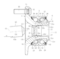
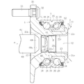
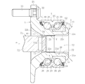
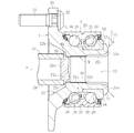
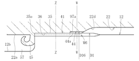
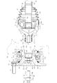
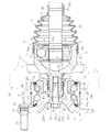
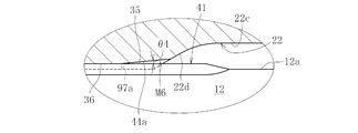
- FIG. 1 shows a wheel bearing device according to a first embodiment.
- This wheel bearing device is a hub wheel 1, a double row rolling bearing 2 and a constant velocity universal joint 3 integrated with each other. 1 and the stem shaft 12 of the outer joint member of the constant velocity universal joint 3 that is inserted into the hole 22 of the hub wheel 1 are coupled to each other through an uneven fitting structure M.
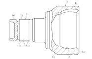
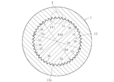
- the constant velocity universal joint 3 includes a plurality of outer rings 5 serving as outer joint members, an inner ring 6 serving as an inner joint member disposed on the inner side of the outer ring 5, and a plurality of torque transmissions interposed between the outer ring 5 and the inner ring 6.
- the ball 7 and the cage 8 that is interposed between the outer ring 5 and the inner ring 6 and holds the ball 7 are configured as main members.
- the inner ring 6 is spline-fitted by press-fitting an end 10a of the shaft 10 into the shaft hole inner diameter 6a and is coupled to the shaft 10 so as to be able to transmit torque. Note that a retaining ring 9 for retaining the shaft is fitted to the end portion 10a of the shaft 10.
- the outer ring 5 includes a mouse part 11 and a stem part (shaft part) 12.
- the mouse part 11 has a bowl shape opened at one end, and a plurality of guide grooves (track grooves) extending in the axial direction on the inner spherical surface 13 thereof. 14 are formed at equal intervals in the circumferential direction.
- the inner ring 6 has a plurality of guide grooves (track grooves) 16 extending in the axial direction formed on the outer spherical surface 15 at equal intervals in the circumferential direction.
- the track groove 14 of the outer ring 5 and the track groove 16 of the inner ring 6 form a pair, and one ball 7 as a torque transmission element (torque transmission member) is provided for each of the tracks constituted by the pair of track grooves 14 and 16. It is incorporated so that it can roll.
- the ball 7 is interposed between the track groove 14 of the outer ring 5 and the track groove 16 of the inner ring 6 to transmit torque.
- the cage 8 is slidably interposed between the outer ring 5 and the inner ring 6, contacts the inner spherical surface 13 of the outer ring 5 at the outer spherical surface, and contacts the outer spherical surface 15 of the inner ring 6 at the inner spherical surface.
- the constant velocity universal joint in this case is an undercut-free type having a straight straight portion at the bottom of each of the track grooves 14 and 16, but a Zepper having no straight straight portion at the bottom. Other constant velocity universal joints such as a mold may be used.
- the boot 18 includes a large diameter portion 18a, a small diameter portion 18b, and a bellows portion 18c that connects the large diameter portion 18a and the small diameter portion 18b.
- the large-diameter portion 18a is externally fitted to the opening of the mouse portion 11, and is fastened by the boot band 19a in this state, and the small-diameter portion 18b is externally fitted to the boot mounting portion 10b of the shaft 10, and in this state, the boot band 19b It is concluded.
- the hub wheel 1 includes a cylindrical portion 20 and a flange 21 provided at an end portion of the cylindrical portion 20 on the outboard side.
- the hole portion 22 of the tubular portion 20 includes a shaft portion fitting hole 22a, a tapered hole 22b on the outboard side, and a large diameter portion 22c on the inboard side.
- a tapered portion (tapered hole) 22d is provided between the large diameter portion 22c and the shaft portion fitting hole 22a.
- the tapered portion 22d is reduced in diameter along the press-fitting direction when the hub wheel 1 and the stem shaft 12 of the outer ring 5 are coupled.
- the inclination angle ⁇ 1 of the tapered portion 22d is, for example, 15 ° to 75 °.
- the outboard side is a side that is outside the vehicle when attached to the vehicle
- the inboard side is a side that is inside the vehicle when attached to the vehicle.
- the rolling bearing 2 includes an inner ring 24 that fits in a stepped portion 23 provided on the inboard side of the tubular portion 20 of the hub wheel 1, and an outer portion that is fitted over the tubular portion 20 through the inner ring 24 of the hub wheel 1. And a member 25.
- the outer member 25 is provided with two rows of outer raceways (outer races) 26 and 27 on its inner circumference, and a first inner raceway (provided on the outer circumference of the first outer raceway 26 and the shaft portion of the hub wheel 1).
- the inner race) 28 is opposed to the second outer raceway surface 27 and the second inner raceway surface (inner race) 29 provided on the outer peripheral surface of the inner ring 24 is opposed to the ball as the rolling element 30 therebetween. Is installed. For this reason, in this wheel bearing device, the hub ring 1 and the inner ring 24 constitute an inner member 39 of the rolling bearing 2. Seal members S1 and S2 are attached to both openings of the outer member 25.
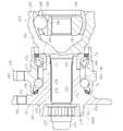
- a knuckle 34 (see FIG. 26 and the like) extending from a vehicle suspension device (not shown) is attached to the outer ring which is the outer member 25. That is, the entire outer surface of the outer member 25 is a cylindrical surface, and this cylindrical surface is a press-fitting surface 25a into which the knuckle 34 is press-fitted. Thus, the outer member 25 can be press-fitted into the cylindrical inner surface of the knuckle. In this case, it is preferable that the relative axial and circumferential deviation between the knuckle 34 and the outer member 25 be regulated by the tightening allowance between the knuckle press-fitting surface 25a and the knuckle inner diameter surface.
- the fitting surface pressure between the outer member 25 and the knuckle 34 ⁇ the fitting area is defined as a fitting load
- a value obtained by dividing the fitting load by the equivalent radial load of the wheel bearing is generated by creep.
- the design coefficient of the outer member 25, that is, the fitting tightening margin between the outer member 25 and the knuckle, is set in consideration of the creep generation limit factor in advance.
- creep means that the bearing surface slightly moves in the circumferential direction due to insufficient fitting tightening allowance or poor processing accuracy of the mating surface, and the mating surface becomes mirrored, and in some cases, seizure or welding occurs with galling.
- circumferential grooves are provided in the knuckle press-fitting surface 25a of the outer member 25 and the inner diameter surface 34a of the knuckle 34, respectively, and retaining rings for retaining the gaps between these circumferential grooves.
- 61 is preferably mounted.
- the end portion on the inboard side of the hub wheel 1 is swaged, and the inner ring 24 is pressed toward the outboard side by the swaged portion 31 to apply a preload to the bearing 2.
- the inner ring 24 can be fastened to the hub wheel 1.
- the end surface 24 a on the inboard side of the inner ring 24 is pressed toward the outboard side along the axial direction, and the end surface 24 b on the outboard side of the inner ring 24 is in contact with or pressed against the end surface 23 a of the step portion 23.
- the flange 21 of the hub wheel 1 is provided with a bolt mounting hole 32, and a hub bolt 33 for fixing the wheel and the brake rotor to the flange 21 is mounted in the bolt mounting hole 32.
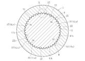
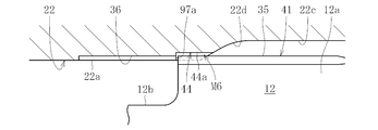
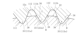
- the concave-convex fitting structure M includes, for example, a convex portion 35 provided on the stem shaft 12 and extending in the axial direction, and an inner diameter surface of the hole portion 22 of the hub wheel 1 (in this case, the shaft portion fitting).
- the inner surface 37) of the hole 22a is formed with a recess 36, and the entire fitting contact portion 38 of the projection 35 and the recess 36 of the hub wheel 1 fitted into the projection 35 is in close contact.
- a plurality of convex portions 35 are arranged at a predetermined pitch along the circumferential direction on the outer peripheral surface of the stem shaft 12 on the side opposite to the mouse portion, and the inner diameter surface of the shaft portion fitting hole 22a of the hole portion 22 of the hub wheel 1
- a plurality of concave portions 36 into which the convex portions 35 are fitted to 37 are formed along the circumferential direction. That is, the convex part 35 and the concave part 36 fitted to this are tight-fitted over the entire circumference in the circumferential direction.
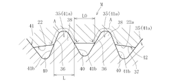
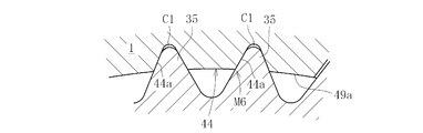
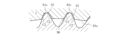
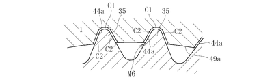
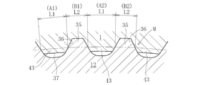
- each convex portion 35 has a triangular shape (mountain shape) having a convex rounded apex in cross section, and the fitting contact portion (concave fitting portion) 38 of each convex portion 35 is shown in FIG. 2B. It is the range A shown, and is the range from the middle part of the mountain in the cross section to the summit. Further, a gap 40 is formed on the inner diameter side with respect to the inner diameter surface 37 of the hub wheel 1 between the adjacent convex portions 35 in the circumferential direction.
- the hub wheel 1 and the stem shaft 12 of the outer ring 5 of the constant velocity universal joint 3 can be connected via the concave-convex fitting structure M.
- the end portion on the inboard side of the hub wheel 1 is swaged and preload is applied to the rolling bearing 2 by the swaged portion 31, so that the mouth portion 11 of the outer ring 5 is applied to the mouth portion 11. Therefore, it is not necessary to apply a preload to the inner ring 24.
- the end portion of the hub wheel 1 in this case, the outer end surface 31a of the crimping portion 31
- the opposing surface of the outer ring 5 facing the same the back surface 11a of the mouse portion 11
- the contact surface pressure in this case is 100 MPa or less.
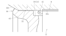
- the shaft portion retaining structure M1 is provided between the end portion of the stem shaft 12 of the outer ring 5 and the inner diameter surface 37 of the hub wheel 1.
- the shaft portion retaining structure M1 includes a diameter-enlarged caulking portion (tapered locking piece) 65 that extends from the end of the stem shaft 12 of the outer ring 5 to the outboard side and is locked in the tapered hole 22b. That is, the diameter-enlarged caulking portion 65 is formed of a ring-shaped body that increases in diameter from the inboard side toward the outboard side, and at least a part of the outer peripheral surface 65a is in pressure contact with or in contact with the tapered hole 22b.
- the foreign matter intrusion prevention means W to the concave / convex fitting structure M is arranged on the inboard side of the concave / convex fitting structure M (which is the inner side of the vehicle when attached to the vehicle) and the concave / convex. They are provided on the outboard side of the fitting structure M (the side that is outside the vehicle when attached to the vehicle).
- the outboard-side foreign matter intrusion prevention means W2 is constituted by a sealing material (not shown) interposed between a tapered locking piece 65, which will be described later, which is an engaging portion, and an inner diameter surface of the tapered hole 22b. I can.
- the sealing material is applied to the tapered locking piece 65. That is, it is only necessary to apply sealing materials (sealing agents) made of various resins that are cured after application and can exhibit sealing properties between the tapered locking piece 65 and the inner diameter surface of the tapered hole 22b.
- this sealing material the thing which does not deteriorate in the atmosphere where this wheel bearing apparatus is used is selected.
- the inboard foreign matter intrusion preventing means W1 can be configured by bringing the outer end surface 31a of the crimping portion 31 of the hub wheel 1 into contact with the back surface 11a of the mouse portion 11.
- a sealing material may be applied to at least one of the outer end surface 31a and the back surface 11a.
- a sealing material may be interposed in the fitting contact portion 38 and the gap 40 between the convex portion 35 and the concave portion 36, thereby forming the foreign matter intrusion prevention means W (W3).
- a sealing material (sealant) made of various resins that can be cured after application and exhibit sealing properties at the fitting contact portion 38 may be applied to the surface of the convex portion 35.
- the concave portion 36 is formed by the convex portion 35 by press-fitting the stem shaft 12 of the outer ring 5 into the hub wheel 1 as will be described later. If press-fitting is performed at this time, the material protrudes from the concave portion 36 formed by the convex portion 35 to form a protruding portion 45 (see FIG. 3).
- the protruding portion 45 is the material of the capacity of the concave portion 36 into which the concave portion fitting portion of the convex portion 35 is inserted (fitted), and is extruded from the concave portion 36 to be formed, and is cut to form the concave portion 36. Or both extruded and cut. For this reason, in the wheel bearing device shown in FIG. 1 and the like, the pocket portion 50 for accommodating the protruding portion 45 is provided in the stem shaft 12.
- the pocket portion 50 is formed by providing a circumferential groove 51 at the shaft end edge of the spline 41 of the stem shaft 12. On the side opposite to the spline from the circumferential groove 51, an end diameter enlarged caulking portion (tapered locking piece) 65 constituting the shaft portion retaining structure M1 is formed.
- the outer diameter portion of the stem shaft 12 of the outer ring 5 of the constant velocity universal joint 3 is subjected to thermosetting treatment, and a convex portion 41 a and a concave portion 41 b along the axial direction are formed on the hardened layer H.
- a spline 41 is formed.
- the convex part 41a of the spline 41 is cured, and the convex part 41a becomes the convex part 35 of the concave-convex fitting structure M.
- the range of the hardened layer H in this embodiment is from the outer end edge of the spline 41 to a part of the bottom wall of the mouth portion 11 of the outer ring 5 as shown by the cross hatched portion.
- various heat treatments such as induction hardening and carburizing and quenching can be employed.
- induction hardening is a hardening method that applies the principle of heating a conductive object by placing Joule heat in a coil through which high-frequency current flows, and generating Joule heat by electromagnetic induction. is there.
- carburizing and quenching is a method in which carbon is infiltrated / diffused from the surface of a low carbon material and then quenched.
- a hardened layer H1 is formed on the outer diameter side of the hub wheel 1 by induction hardening, and the inner diameter side of the hub wheel 1 is left unfired.
- the range of the hardened layer H1 in this embodiment is from the base portion of the flange 21 to the vicinity of the caulking portion of the step portion 23 into which the inner ring 24 is fitted, as shown by the cross-hatched portion.
- the surface is hard, and the inside can be left as it is, so that the inner diameter side of the hub wheel 1 can be kept unfired.
- an uncured portion (unburned state) where no thermosetting treatment is performed.
- the hardness difference between the hardened layer H of the stem shaft 12 of the outer ring 5 and the uncured portion of the hub wheel 1 is 20 points or more in HRC. Specifically, the hardness of the hardened layer H is set to about 50 HRC to 65 HRC, and the hardness of the uncured portion is set to about 10 HRC to about 30 HRC.
- the projecting direction intermediate portion of the convex portion 35 corresponds to the position of the concave portion forming surface (in this case, the inner diameter surface 37 of the hole 22 of the hub wheel 1) before the concave portion is formed. That is, as shown in FIG. 4, the inner diameter dimension D of the inner diameter surface 37 of the hole 22 is set to the maximum outer diameter of the convex portion 35, that is, the maximum of the circle connecting the vertices of the convex portion 35 that is the convex portion 41 a of the spline 41.
- the spline 41 can be formed by various processing methods such as rolling processing, cutting processing, press processing, and drawing processing, which are known publicly known means. Moreover, various heat processing, such as induction hardening and carburizing hardening, can be employ
- the diameter-enlarged caulking portion 65 is configured from the outer peripheral edge portion of the end surface 12 a of the stem shaft 12.
- the cylindrical portion 66 for projecting is projected along the axial direction.
- the outer diameter D4 of the cylindrical portion 66 is set smaller than the inner diameter D of the fitting hole 22a of the hole portion 22. That is, as will be described later, the cylindrical portion 66 serves as a guide portion for alignment when the stem shaft 12 is press-fitted into the hole 22 of the hub wheel 1.
- the inner diameter D3 of the large-diameter portion 22c of the hub wheel 1 is set larger than the maximum diameter dimension (circumscribed circle diameter) D1.
- the cylindrical portion 66 itself is press-fitted into the fitting hole 22a. At this time, if the center is misaligned, the convex portion 35 of the concave-convex fitting structure M is press-fit as it is, and the shaft portion 12 and the hub wheel are in a state where the shaft center of the stem shaft 12 and the shaft center of the hub wheel 1 are not aligned. 1 is connected. If the outer diameter D4 of the cylindrical portion 66 is too smaller than the hole diameter of the fitting hole 22a, it does not function for alignment. Therefore, it is preferable that the minute gap between the outer diameter surface of the cylindrical portion 66 and the inner diameter surface of the fitting hole 22a of the hole portion 22 is set to about 0.01 mm to 0.2 mm.
- the stem shaft 12 of the outer ring 5 is inserted (press-fitted) into the hub wheel 1 in a state where the shaft center of the hub wheel 1 is aligned with the shaft center of the outer ring 5 of the constant velocity universal joint. Further, a sealing material is applied to the surface of the convex portion 35. At this time, since the tapered portion 22d having a reduced diameter along the press-fitting direction is formed in the hole portion 22 of the hub wheel 1, the tapered portion 22d can constitute a guide at the start of press-fitting.
- the diameter D of the inner diameter surface 37 of the hole 22, the maximum diameter D1 of the protrusion 35, and the outer diameter (diameter dimension) D2 of the bottom of the recess of the spline 41 are as described above. Since the hardness of the convex portion 35 is 20 points or more larger than the hardness of the inner diameter surface 37 of the hole portion 22, if the shaft 10 is pressed into the hole portion 22 of the inner ring 6, the convex portion 35 bites into the inner diameter surface 37. Thus, the convex portion 35 forms the concave portion 36 into which the convex portion 35 is fitted along the axial direction.
- the formed protruding portion 45 is housed in the pocket portion 50 while curling. That is, a part of the material scraped off or pushed out from the inner diameter surface of the hole portion 22 enters the pocket portion 50.
- the entire fitting contact portion 38 between the convex portion 35 at the end of the stem shaft 12 and the concave portion 36 fitted therein is in close contact.
- the shape of the convex portion 35 is transferred to the other-side concave portion forming surface (in this case, the inner diameter surface 37 of the hole portion 22).
- the convex portion 35 bites into the inner diameter surface 37 of the hole portion 22, so that the hole portion 22 is slightly expanded in diameter, and the convex portion 35 is allowed to move in the axial direction.
- the hole 22 is reduced in diameter to return to the original diameter.
- the hub wheel 1 is elastically deformed in the radial direction when the convex portion 35 is press-fitted, and a preload corresponding to this elastic deformation is applied to the tooth surface of the convex portion 35 (surface of the concave portion fitting portion). For this reason, the concave / convex fitting structure M in which the entire concave portion fitting portion of the convex portion 35 is in close contact with the corresponding concave portion 36 can be reliably formed.
- a female spline 42 that is in close contact with the male spline 41 is formed on the inner diameter surface of the hole 22 of the hub wheel 1 by the spline (male spline) 41 on the stem shaft 12 side. Further, the fitting contact portion 38 between the convex portion 35 and the concave portion 36 is sealed with a sealing material applied to the surface of the convex portion 35.
- the concave-convex fitting structure M is configured.
- the concave-convex fitting structure M is arranged at a position directly below the raceway surfaces 26, 27, 28, 29 of the rolling bearing 2.
- the direct under-position is a position that does not correspond to the radial direction with respect to the ball contact portion position of the raceway surfaces 26, 27, 28, and 29.
- the height of the convex portion 35 provided on the outer diameter surface of the stem shaft 12 is h
- the ratio is ⁇ d / 2h, 0.3 ⁇ d / 2h ⁇ 0.86.
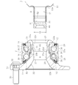
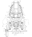
- a step surface G is provided on the outer diameter surface of the mouse part 11 of the outer ring 5 as shown in FIG.
- the jig K may be engaged with the step surface G, and a press-fitting load (axial load) may be applied from the press-fitting jig K to the step surface G.
- step difference surface G can be comprised by the circumferential direction groove
- the press-fitting jig K can be constituted by a ring-shaped body 47 made of, for example, a split mold. That is, the ring-shaped body 47 includes a plurality (at least two) of segments 47a, and is formed in a ring shape by combining the segments 47a.
- the ring-shaped body 47 formed by combining the segments 47a in a ring shape includes a main body annular portion 57, a tapered portion 58 connected to the main body annular portion 57, and an inner portion protruding from the tapered portion 58 toward the inner diameter side. It consists of a buttock 59.
- the inner flange 59 of the press-fitting jig K is brought into contact with the step surface G formed by the circumferential groove, and in this state, the load (pressing force) in the direction of the arrow E (axial direction) in FIG. ) Is applied to the press-fitting jig 55.
- this load can be applied to the outer ring 5 via the inner flange 53 engaged with the step surface G, and the stem shaft 12 of the outer ring 5 is press-fitted into the hole 22 of the hub wheel 1.
- various axial reciprocating mechanisms such as a press mechanism, a cylinder mechanism, and a ball screw mechanism can be used to apply the axial load to the press-fitting jig K.
- the stepped surface G can be constituted by a concave portion disposed at a predetermined pitch along the circumferential direction without being constituted by a circumferential groove, and moreover, it is not a groove or a concave portion. You may comprise by a convex part.
- the stem shaft 12 is press-fitted into the hole 22 of the hub wheel 1
- a method of applying a press-fitting load to the end surface 5a on the inboard side of the outer ring 5 may be used, and a stepped surface is formed on the outer diameter surface of the outer ring 5. It is possible to press-fit without providing G. That is, the jig K1 shown in FIG. 8 can be used.
- the jig K1 can be composed of a bottomed short cylinder.
- the jig K1 includes a main body 98 made of a cylindrical body and a bottom wall 99 that closes an opening on the inboard side of the main body 98.
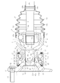
- 9 and 10 show the Zepper type constant velocity universal joints in which the groove bottoms of the track grooves 14 and 16 each have an arcuate portion.
- Other constant velocity universal joints such as an undercut free type in which the groove bottoms of the track grooves 14 and 16 have straight straight portions may be used.
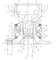
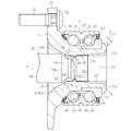
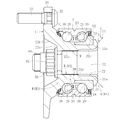
- FIG. 6 shows a state in which the stem shaft 12 of the outer ring 5 and the hub wheel 1 are integrated through the concave and convex fitting structure M by press-fitting into the stem shaft 12 of the outer ring 5 and the hole 22 of the hub wheel 1.
- the cylindrical portion 66 protrudes from the fitting hole 22a toward the tapered hole 22b.
- the diameter of the cylindrical portion 66 is expanded using a jig 67 as shown in FIGS.
- the crimping jig 67 includes a columnar main body portion 67a and a distal end bulging portion 67b provided on the distal end surface of the main body portion 67a.
- the tip bulging portion 67b can be fitted into the cylindrical portion 66 in a loose fit.
- the outer peripheral surface of the tip bulging portion 67b is a loose rounded portion on the main body side.
- the tip bulging portion 67b of the caulking jig 67 is fitted into the cylindrical portion 66, and the caulking jig 67 is swung while being pressed in the direction of the arrow ⁇ as shown in FIGS. .
- the swinging means swinging so that the jig axis O1 is inclined with respect to the apparatus axis O with the apparatus axis O as the rotation axis and the intersection of the jig axis O1 and the apparatus axis O as a fulcrum. Is.
- the peripheral wall surface of the tip bulging portion 67b presses the inner diameter surface of the cylindrical portion 66 toward the outer diameter side.
- the cylindrical portion 66 is plastically deformed radially outward to form an enlarged diameter crimped portion (tapered locking piece) 65 as shown in FIG. That is, in the shaft portion retaining structure M1, the cylindrical portion 66 provided at the shaft end portion of the stem shaft 12 is plastically deformed radially outward by rocking caulking by the rocking caulking jig 67. It is comprised by the hook structure which becomes.
- the jig K as shown in FIG. 7 or the jig K1 as shown in FIG. 8 can be used.
- the jig K can receive an axial load due to swing caulking through the inner flange portion 53 engaged with the step surface G.
- the main body portion 98 is fitted to the opening side of the mouse portion 11 of the outer ring 5, and the inner surface 99a of the bottom wall 99 is brought into contact with the opening end surface 11b of the mouse portion 11, so It can receive the axial load by.
- the concave-convex fitting structure M in which the entire fitting contact portion 38 between the convex portion 35 of the stem shaft 12 and the concave portion 36 of the hub wheel 1 is in close contact can be formed reliably. Moreover, it is not necessary to form a spline portion or the like on the member in which the concave portion 36 is formed, which is excellent in productivity, and does not require the phase alignment between the splines. The tooth surface can be prevented from being damaged, and a stable fitting state can be maintained.
- the entire fitting contact portion 38 between the convex portion 35 and the concave portion 36 is in close contact with each other. Therefore, in the fitting structure M, there is no gap in which play occurs in the radial direction and the circumferential direction. . For this reason, all the fitting parts contribute to rotational torque transmission, stable torque transmission is possible, and no abnormal noise is generated.
- the shaft part retaining structure M1 is a hook structure in which the cylindrical part is plastically deformed radially outward, the conventional screw fastening can be omitted. For this reason, it is not necessary to form the screw part which protrudes from the hole part 22 of the hub wheel 1 in the stem axis
- This shaft part retaining structure M1 can effectively prevent the stem shaft 12 of the outer joint member from coming off from the hole 22 of the hub wheel 1 in the axial direction. As a result, a stable connected state can be maintained, and the quality of the wheel bearing device can be improved.
- the caulking load at the time of caulking is relatively small, and the caulking portion 65 is increased in thickness, or the caulking portion 65 is pressed against the inner diameter surface of the hub wheel through a large pressing force. be able to. Thereby, a stronger retaining mechanism (structure) can be provided. Further, by providing such a strong retaining mechanism (structure) M1, the bending rigidity of the stem shaft 12 is improved and the bending becomes strong.
- the portion receiving the load (the load receiving portion of the outer joint member of the constant velocity universal joint 3, for example, a step provided on the outer diameter surface of the outer joint member) Deformation of the surface and the opening side end surface of the outer joint member).
- the crimped portion 31 and the back surface 11a of the mouth portion 11 of the outer ring 5 By bringing the crimped portion 31 and the back surface 11a of the mouth portion 11 of the outer ring 5 into contact with each other, the bending rigidity in the axial direction is improved, the bending strength is improved, and a high-quality product excellent in durability is obtained. Become.
- positioning at the time of press-fitting can be configured by this contact. As a result, the dimensional accuracy of the wheel bearing device can be stabilized, and the axial length of the concave-convex fitting structure M disposed along the axial direction can be ensured to be stable. Can be improved.
- a seal structure can be formed by this contact, foreign matter can be prevented from entering the concave-convex fitting structure M from the crimping portion 31 side, and the concave-convex fitting structure M can maintain a stable fitting state for a long period of time.
- the stem shaft 12 of the outer ring 5 can be press-fitted without considering the preload, and the connectivity (assembly property) between the hub wheel 1 and the outer ring 5 can be improved.
- the contact surface pressure between the caulking portion 31 of the hub wheel 1 and the back surface 11a of the mouse portion 11 exceeds 100 MPa, abnormal noise may be generated. That is, when a large torque load is applied, a difference occurs in the amount of twist between the outer ring 5 of the constant velocity universal joint 3 and the hub wheel 1, and this difference causes a sudden contact between the outer ring 5 of the constant velocity universal joint 3 and the hub wheel 1. Slip occurs and abnormal noise occurs. On the other hand, if the contact surface pressure is 100 MPa or less as in the present invention, it is possible to prevent a sudden slip and to suppress the generation of abnormal noise. Thereby, a quiet wheel bearing device can be configured. In addition, even if the contact surface pressure is 100 MPa or less, it is preferable that the contact surface pressure be not less than the surface pressure that can constitute the seal structure.
- the protruding portion 45 By providing the pocket portion 50 for storing the protruding portion 45 generated by forming the concave portion by the press-fitting, the protruding portion 45 can be held (maintained) in the pocket portion 50, and the protruding portion 45 is inside the vehicle outside the apparatus. There is no intrusion. That is, the protruding portion 45 can be kept stored in the pocket portion 50, and it is not necessary to perform the removal process of the protruding portion 45, the number of assembling operations can be reduced, and the assembling workability can be improved. Cost reduction can be achieved.
- the protruding portion 45 in the pocket portion 50 does not protrude to the guide portion side.
- the storage of the protruding portion 45 becomes more stable.
- the guide portion is for alignment, the stem shaft 12 can be press-fitted into the hub wheel 1 while preventing misalignment. For this reason, the outer joint member and the hub wheel 1 can be connected with high accuracy, and stable torque transmission is possible.
- the convex portion 35 bites into the concave portion forming surface during press-fitting, and the concave portion 36 is reliably formed. can do. That is, the press-fitting allowance with respect to the other side of the convex part 35 can be taken sufficiently. As a result, the formability of the concave-convex fitting structure M is stabilized, there is no variation in press-fit load, and a stable torsional strength is obtained.
- the stem shaft 12 is provided with a guide portion for alignment, that is, a cylindrical portion 66, the stem shaft 12 can be press-fitted into the hub wheel 1 without misalignment, and the concave portion 36 formed by the convex portion 35. Formation can be performed stably. For this reason, the uneven fitting structure M can be configured with high accuracy. Further, since the taper portion 22d can constitute a guide at the start of press-fitting, the stem shaft 12 of the outer ring 5 can be press-fitted into the hole portion 22 of the hub wheel 1 without causing a deviation, and stable. Torque transmission is possible.
- the convex portion 35 of the concave-convex fitting structure M is provided on the stem shaft 12 of the outer ring 5, and the hardness of the axial end portion of the convex portion 35 is set from the hole inner diameter portion of the hub wheel 1. If the stem shaft 12 is press-fitted into the hole portion 22 of the hub wheel 1, the hardness on the shaft portion side can be increased and the rigidity of the shaft portion can be improved.
- the concave-convex fitting structure M By arranging the concave-convex fitting structure M at a position directly below the raceway surface of the rolling bearing 2, the occurrence of hoop stress on the bearing raceway surface is suppressed. As a result, it is possible to prevent a bearing failure such as a decrease in rolling fatigue life, occurrence of cracks, and stress corrosion cracking, and a high-quality bearing 2 can be provided.
- the spline 41 formed on the stem shaft 12 uses small teeth with a module of 0.5 or less, so that the formability of the spline 41 can be improved and the press-fit load is reduced. Can be achieved.
- the convex part 35 can be comprised with the spline normally formed in this kind of shaft, this convex part 35 can be easily formed at low cost.
- the outer peripheral surface 25a of the outer member 25 of the bearing 2 is fitted and assembled into the knuckle 34 on the vehicle body side.
- the fitting integration here means that the integration of both is completed by fitting the outer member 25 to the knuckle 34.
- This incorporation can be performed, for example, by press-fitting the cylindrical outer peripheral surface 25 a of the outer member 25 into the cylindrical inner peripheral surface 34 a of the knuckle 34.
- the difference between the outer diameter D1 of the stem shaft 12 and the inner diameter D of the hole 22 of the hub wheel 1 is ⁇ d
- the height of the convex portion is h (see FIG. 4)
- the ratio is ⁇ d / 2h.
- 0.3 ⁇ d / 2h ⁇ 0.86, so that the press-fitting allowance of the convex portion 35 can be sufficiently taken. That is, when ⁇ d / 2h is 0.3 or less, the torsional strength is low, and when ⁇ d / 2h exceeds 0.86, the entire convex portion 35 is caused by a misalignment or a press-fit inclination at the time of a fine press-fit.
- the tapered portion 22d can constitute a guide at the start of press-fitting, the stem shaft 12 of the outer ring 5 can be pressed into the hole portion 22 of the hub wheel 1 without causing displacement, and stable torque can be obtained. Communication is possible. Further, since the cylindrical portion 66 has an outer diameter D4 of the cylindrical portion 66 set smaller than the inner diameter D of the fitting hole 22a of the hole portion 22, the cylindrical portion 66 becomes a centering member and prevents stem misalignment. The shaft can be press-fitted into the hub wheel, enabling more stable press-fitting.
- the stem part retaining structure M1 can effectively prevent the stem shaft 12 of the outer ring 5 from coming out of the hole part 22 of the hub wheel 1 (particularly in the axial direction to the shaft side). As a result, a stable connected state can be maintained, and the quality of the wheel bearing device can be improved. Moreover, since the shaft portion retaining structure M1 is the tapered locking piece 65, conventional screw fastening can be omitted. For this reason, it is not necessary to form the screw part which protrudes from the hole part 22 of the hub wheel 1 in the stem axis
- a part of the stem shaft 12 of the outer ring 5 has only to be increased in diameter, and the shaft portion retaining structure M1 can be easily formed.
- the movement of the outer ring 5 in the anti-joint direction of the stem shaft 12 requires a pressing force in a direction in which the stem shaft 12 is further press-fitted, and the positional deviation of the outer ring 5 in the anti-joint direction is extremely large.
- the bottom of the mouth portion 11 of the outer ring 5 comes into contact with the crimped portion 31 of the hub wheel 1 and the stem shaft 12 of the outer ring 5 comes off from the hub wheel 1 even if it is misaligned in this direction. There is no.
- the convex part 35 can be comprised with the spline normally formed in this kind of shaft, this convex part 35 can be easily formed at low cost.
- work hardening occurs on the recess 36 side.
- work hardening means that when plastic deformation (plastic processing) is applied to an object, the resistance to deformation increases as the degree of deformation increases, and it becomes harder than a material that has not undergone deformation. For this reason, by plastically deforming at the time of press-fitting, the inner diameter surface 37 of the hub wheel 1 on the concave portion 36 side is hardened, and the rotational torque transmission performance can be improved.
- the inner diameter side of the hub wheel 1 is relatively soft. For this reason, it is possible to improve the fitting property (adhesion) when the convex portion 35 on the outer diameter surface of the stem shaft 12 of the outer ring 5 is fitted to the concave portion 36 on the inner diameter surface of the hole portion of the hub wheel 1. It is possible to accurately suppress the occurrence of play in the radial direction and the circumferential direction.
- a seal structure (foreign matter intrusion prevention means W1) is formed by contact between the outer end surface 31a of the crimping portion 31 and the back surface 11a of the mouth portion 11 of the outer ring 5. This seal structure can prevent foreign matter from entering from the inboard side.
- the foreign matter intrusion prevention means W1 and W2 are provided on the inboard side of the concave / convex fitting structure M and the outboard side of the concave / convex fitting structure M as in the above-described embodiment. Intrusion of foreign matters from both axial ends of M is prevented. For this reason, deterioration of adhesion can be avoided more stably over a long period of time.
- the foreign matter intrusion prevention means W3 is provided in which a sealing material is interposed between the fitting contact portions 38 between the convex portions 35 and the concave portions 36, foreign matter can be prevented from entering between the fitting contact portions 38, Improves the reliability of foreign object entry prevention.
- an axial pressing force can be applied to the outer ring 5 through the step surface G of the outer diameter surface of the outer ring 5 of the constant velocity universal joint 3. That is, it is possible to secure an axial direction pressing force application portion and to press the vicinity of the stem shaft of the outer ring 5 which is a press-fitting shaft, thereby enabling stable press-fitting.
- a groove is provided on the outer diameter surface of the outer ring 5 of the constant velocity universal joint 3 and the radial end surface of the groove is a stepped surface G, a protrusion is provided on the outer diameter surface of the outer ring 5;
- a stepped surface G may be used as the projection radial end surface. In these cases, the reliability of securing the axial pressing force application portion is improved, and a more stable press-fitting operation can be performed.
- the outer ring 5 It is not necessary to provide the step surface G on the outer diameter surface, and press-fitting can be performed at low cost.
- the jig 67 includes a columnar main body portion 68 and a truncated cone portion 69 that is connected to the distal end portion of the main body portion 68.
- the truncated cone portion 69 of the jig 67 has an inclined surface 69a whose inclination angle is substantially the same as the inclination angle of the tapered hole 22b, and whose outer diameter is the same as or slightly cylindrical with the inner diameter of the cylindrical portion 66.
- the dimension is set to be smaller than the inner diameter of the shaped portion 66.
- a load in the direction of the arrow ⁇ is applied by inserting the truncated cone portion 69 of the jig 67 through the tapered hole 22b, whereby the cylindrical portion 66 is arranged on the inner diameter side of the cylindrical portion 66 shown in FIG.
- a diameter expansion force in the direction of arrow ⁇ in which the diameter of 66 expands is applied.
- at least a part of the cylindrical portion 66 is pressed to the inner diameter side of the tapered hole 22b by the truncated cone portion 69 of the jig 67, and foreign matter intrusion prevention means W2 is formed on the inner diameter surface of the tapered hole 22b.
- the shaft part slip-off preventing structure M1 can be configured by being pressed or in contact with the sealing material.
- the hub wheel 1, the constant velocity universal joint 3, etc. It is sufficient to receive a part of this by a fixing member.
- the inner diameter surface of the cylindrical portion 66 may be tapered so as to increase in diameter toward the shaft end. If it is set as such a shape, it is also possible to shape
- the cylindrical portion 66 may be notched, and the conical surface of the truncated cone portion 69 of the jig 67 is partially arranged in the circumferential direction. Things can be used. When a notch is made in the cylindrical portion 66, the cylindrical portion 66 can be easily expanded in diameter. Further, in the case where the conical surface of the truncated cone part 69 of the jig 67 is partially arranged in the circumferential direction, a part where the diameter of the cylindrical part 66 is enlarged becomes a part on the circumference. The indentation load can be reduced.
- FIG. 13 shows a second embodiment.
- a stepped surface 22e extending in the radial direction is formed between the tapered hole 22b and the shaft fitting hole 22a in the hole 22 of the hub wheel 1.
- the diameter-enlarged caulking portion 65 is engaged with the stepped surface 22e.
- the diameter-enlarged caulking portion 65 formed by plastic deformation radially outward by the rocking caulking by the rocking caulking jig 67 is formed. That is, the diameter-enlarged caulking portion 65 in this case is bent so as to be bent substantially at right angles to the device axis, and the end surface on the inboard side abuts or presses against the stepped surface 22e.
- FIG. 12 Other configurations of the wheel bearing device shown in FIG. 12 are the same as those of the wheel bearing device shown in FIG. 1, and therefore, the same members as those in FIG. . For this reason, even if it is a wheel bearing apparatus shown in FIG. 13, there exists an effect similar to the wheel bearing apparatus shown in FIG.
- FIG. 14 shows a third embodiment, and the shaft portion retaining structure M1 of the wheel bearing device has a part of the stem shaft 12 having an outer diameter without forming a cylindrical portion 66 as shown in FIG. A tapered locking piece 70 protruding in the direction is provided.
- a jig 71 shown in FIG. 15 is used.
- the jig 71 includes a columnar main body 72 and a short cylindrical portion 73 connected to the distal end of the main body 72, and a notch 74 is provided at the distal end of the outer peripheral surface of the short cylindrical portion 73.
- a tip wedge portion 75 is formed in the jig 71.
- the sectional shape of the tip wedge portion 75 is an inclined surface on the outer diameter side, and a notch that forms this inclined surface is formed.
- the outer diameter side of the end portion of the stem shaft 12 is expanded by the portion 74.
- the tapered locking piece 70 comes into pressure contact with or contacts the inner diameter surface of the tapered hole 22b.
- the stem shaft 12 of the outer ring 5 extends axially from the hole 22 of the hub wheel 1 in the same manner as the tapered locking piece 65 shown in FIG. It can be effectively prevented from coming off.
- the inner diameter surface of the tip wedge portion 75 may be tapered.
- FIG. 17 shows a fourth embodiment, and the shaft portion retaining structure M1 of the wheel bearing device is formed by tightening a part of the stem shaft 12 so as to protrude in the outer diameter direction.
- a piece 76 is used.
- the hole portion 22 of the hub wheel 1 is provided with a stepped surface 22e between the fitting hole 22a and the tapered hole 22b, and the outer hook-shaped locking piece 76 is locked to the stepped surface 22e. is doing.
- a jig 77 shown in FIG. 18 is used.
- the jig 77 includes a cylindrical body 78.
- the outer diameter D5 of the cylindrical body 78 is set larger than the outer diameter D7 of the end portion of the stem shaft 12, and the inner diameter D6 of the cylindrical body 78 is set smaller than the outer diameter D7 of the end portion of the stem shaft 12.
- FIG. 13 the outer peripheral side of the end surface 12 a of the stem shaft 12 can be crushed to form an outer hook-like locking piece 76.
- the outer hook-shaped locking piece 76 is locked to the stepped surface 22e, so that it is the same as the tapered locking piece 65 shown in FIG.
- the stem shaft 12 of the outer ring 5 can be effectively prevented from coming off from the hole 22 of the hub wheel 1 in the axial direction. As a result, a stable connected state can be maintained, and the quality of the wheel bearing device can be improved.
- the outer hook-like locking piece 76 is formed along the circumferential direction.
- a predetermined pitch for example, 90 ° pitch
- a plurality of outer hook-like locking pieces 76 are provided. Arranged at a predetermined pitch along the circumferential direction.
- the outer hook-shaped locking pieces 76 are locked to the stepped surface 22e. Therefore, it is possible to effectively prevent the stem shaft 12 of the outer ring 5 from coming off from the hole 22 of the hub wheel 1 in the axial direction.
- the seventh embodiment can be implemented by using a bolt and nut connection as shown in FIG. 21 of the fifth embodiment, or by using a retaining ring as shown in FIG. 22 of the sixth embodiment.
- a coupling means such as welding may be used.
- a screw shaft portion 80 is connected to the stem shaft 12, and a nut member 81 is screwed to the screw shaft portion 80.
- the nut member 81 is in contact with the stepped surface 22 e of the hole 22. This restricts the stem shaft 12 from coming out from the hole 22 of the hub wheel 1 toward the shaft.
- a shaft extension 83 is provided on the outboard side of the spline 41, a circumferential groove 84 is provided in the shaft extension 83, and a retaining ring 85 is fitted in the circumferential groove 84.
- the stem shaft 12 is provided with a step portion 22f in the hole portion 22 of the hub wheel 1 between the fitting hole 22a and the tapered hole 22b to which the retaining ring 85 is locked. Accordingly, the retaining ring 85 is locked to the step portion 22f to restrict the stem shaft 12 from coming out from the hole portion 22 of the hub wheel 1 to the shaft side.
- the outer peripheral surface of the end portion of the stem shaft 12 and the opening edge portion on the stepped surface 22e side of the fitting hole 22a are joined by welding. This restricts the stem shaft 12 from coming out from the hole 22 of the hub wheel 1 toward the shaft.
- the welded portion 108 may be disposed at a predetermined pitch along the circumferential direction over the entire circumference.
- the foreign matter intrusion preventing means W1, W2, and W3 can be configured.
- the foreign matter intrusion prevention means W2 can be formed by interposing a sealing material between the enlarged diameter crimped portion 65 and the stepped surface 22e.
- the foreign matter intrusion prevention means W2 can be formed by interposing a sealing material between the tapered locking piece 70 and the inner diameter surface of the tapered hole 22b.
- the foreign substance intrusion prevention means W2 can be formed by interposing a sealing material between the outer hook-shaped locking piece 76 and the stepped surface 22e.
- the foreign matter intrusion prevention means W2 can be formed by the retaining ring 85 to be fitted.
- the foreign matter intrusion prevention means W2 can be formed by the welding site 108 over the entire circumference.
- the foreign matter intrusion preventing means W1 and W3 are the same as the wheel bearing device shown in FIG.
- a seal structure (foreign matter intrusion prevention means W1) is formed by contact between the outer end surface 31a of the crimping portion 31 and the back surface 11a of the mouth portion 11 of the outer ring 5. This seal structure can prevent foreign matter from entering from the inboard side.
- the foreign matter intrusion prevention means W1 and W2 are provided on the inboard side of the concave / convex fitting structure M and the outboard side of the concave / convex fitting structure M as in the above-described embodiment. Intrusion of foreign matters from both axial ends of M is prevented. For this reason, deterioration of adhesion can be avoided more stably over a long period of time.
- the foreign matter intrusion prevention means W3 is provided in which a sealing material is interposed between the fitting contact portions 38 between the convex portions 35 and the concave portions 36, foreign matter can be prevented from entering between the fitting contact portions 38, Improves the reliability of foreign object entry prevention.
- the shaft portion retaining structure M1 may not be provided.
- the circumferential groove 51 is a plane in which the side surface 51a on the spline 41 side is orthogonal to the axial direction, and the side surface 51b on the anti-spline side extends from the groove bottom 51c to the anti-spline. It is a taper surface which expands toward the side.
- a disc-shaped flange portion 52 for alignment is provided on the side opposite to the spline from the side surface 51 b of the circumferential groove 51.
- the outer diameter D4a of the flange 52 is set to be the same as the hole diameter of the fitting hole 22a of the hole 22 or slightly smaller than the hole diameter of the fitting hole 22a. In this case, a minute gap t is provided between the outer diameter surface 52 a of the flange portion 52 and the inner diameter surface of the fitting hole 22 a of the hole portion 22.
- the protruding portion 45 in the pocket portion 50 does not protrude to the flange 52 side.
- the storage of the protruding portion 45 becomes more stable.
- the flange portion 52 is for alignment, the stem shaft 12 can be press-fitted into the hub wheel 1 while preventing misalignment. For this reason, the outer ring 5 and the hub wheel 1 can be connected with high accuracy, and stable torque transmission is possible.
- the outer diameter is preferably set to be slightly smaller than the diameter of the fitting hole 22a of the hole 22 of the hub wheel 1. That is, if the outer diameter of the flange 52 is the same as the hole diameter of the fitting hole 22a or larger than the hole diameter of the fitting hole 22a, the flange 52 itself is press-fitted into the fitting hole 22a. At this time, if the center is misaligned, the convex portion 35 of the concave-convex fitting structure M is pressed in as it is, and the stem shaft 12 and the hub wheel are in a state where the shaft center of the stem shaft 12 and the shaft center of the hub wheel 1 are not aligned. 1 is connected.
- the minute gap t between the outer diameter surface 52a of the flange 52 and the inner diameter surface of the fitting hole 22a of the hole portion 22 is preferably set to about 0.01 mm to 0.2 mm.
- the flange portion 52 for aligning the stem shaft 12 may be omitted.
- FIG. 26 shows that the hub wheel 1 and the stem shaft 12 of the outer joint member of the constant velocity universal joint 3 inserted into the hole 22 of the hub wheel 1 are detachably coupled via the concave-convex fitting structure M. It has been made.
- the hub wheel 1 in this case has a cylindrical portion 20 and a flange 21 provided at an end portion of the cylindrical portion 20 on the outboard side, as shown in FIGS.
- the hole portion 22 of the cylindrical portion 20 has a shaft portion fitting hole 22a and a tapered hole 22b on the outboard side, and protrudes in the inner diameter direction between the shaft portion fitting hole 22a and the tapered hole 22b.
- An inner wall 22g is provided.
- a recess 63 is provided on the end surface of the inner wall 22g on the side opposite to the shaft fitting hole.
- the hole portion 22 has a large-diameter portion 22c on the opening side on the side opposite to the inner wall side from the shaft portion fitting hole 22a, and a small-diameter portion 48 on the inner wall side from the shaft portion fitting hole 22a.
- a tapered portion 22d is provided between the large diameter portion 22c and the shaft portion fitting hole 22a. The tapered portion 22d is reduced in diameter along the press-fitting direction when the hub wheel 1 and the stem shaft 12 of the outer ring 5 are coupled.
- the stem shaft 12 of the outer ring 5 is provided with a screw hole 64 that opens at the end surface on the outboard side at the axial center.
- the screw hole 64 is a tapered portion 64a whose opening is expanded toward the opening.
- a small-diameter portion 12b is provided at the end portion of the stem shaft 12 on the outboard side. That is, the stem shaft 12 includes a main body portion 12a having a large diameter and a small diameter portion 12b.
- the bolt member 54 is screwed into the screw hole 64 of the stem shaft 12 from the outboard side.
- the bolt member 54 includes a flanged head portion 54a and a screw shaft portion 54b.
- the screw shaft portion 54b has a non-threaded portion 55a on the proximal end side and a threaded portion 55b on the distal end side.
- a through hole 56 is provided in the inner wall 22g, the shaft portion 54b of the bolt member 54 is inserted into the through hole 56, and the screw portion 55b is screwed into the screw hole 64 of the stem shaft 12. As shown in FIG.
- the hole diameter D12 of the through hole 56 is set slightly larger than the shaft diameter (outer diameter) D11 of the non-threaded portion 55a of the shaft portion 54b. Specifically, it is about 0.05 mm ⁇ d1-d2 ⁇ 0.5 mm. Note that the maximum outer diameter of the threaded portion 55b is the same as or slightly smaller than the outer diameter of the large non-threaded portion 55a.
- a shaft press-fitting guide portion M6 that guides press-fitting of the stem shaft 12 during press-fitting is provided on the convex press-fitting start side.
- it consists of a female spline 44 provided in the tapered portion 22 d of the hole portion 22. That is, as shown in FIG. 28A, guide concave portions 44a are provided at a predetermined pitch (in this case, the same pitch as the arrangement pitch of the convex portions 35) on the shaft portion fitting hole 22a side of the tapered portion 22d.
- the bottom diameter D16 of the guide recess 44a is the maximum outer diameter of the projection 35, that is, the maximum diameter of the circle connecting the vertices of the projection 35 which is the projection 41a of the spline 41.
- (Diameter of circumscribed circle) (shaft outer diameter) D1 a radial clearance C1 is formed between the top of the convex portion 35 and the bottom of the guide concave portion 44a as shown in FIG. 28A.
- each projection 35 of the stem shaft 12 is inserted into each guide recess 44a of the shaft press-fitting guide portion M6.
- the shaft center of the hub wheel 1 and the shaft center of the outer ring 5 are aligned with each other, and the end of each guide recess 44a on the uneven fitting structure side is in the press-fitting direction. Since it is a flat surface 97a (see FIG. 27) perpendicular to the surface, it can receive the press-fitting start end surface 35a of the convex portion 35 and can press-fit from this state.
- the inner diameter dimension D of the inner diameter surface 37 of the part fitting hole 22a, the maximum diameter dimension D1 of the protrusion 35, and the outer diameter dimension (diameter dimension) D2 of the bottom of the recess of the spline 41 are as described above.
- the hardness of the convex portion 35 is greater than the hardness of the inner diameter surface 37. Is larger by 20 points or more, so if the stem shaft 12 is press-fitted into the hole 22 of the hub wheel 1, the convex portion 35 bites into the inner diameter surface 37, and the convex portion 35 is fitted into the convex portion 35.
- the concave portion 36 to be formed is formed along the axial direction.
- the bolt member 54 is screwed into the screw hole 64 of the stem shaft 12 from the outboard side.
- the flange portion 60 of the head portion 54a of the bolt member 54 is fitted into the recessed portion 63 of the inner wall 22g.
- the hub wheel 1 is sandwiched between the head 54 a of the bolt member 54 and the concave-convex fitting structure M, or between the head 54 a of the bolt member 54 and the bottom bottom surface (back surface) 11 a of the mouse portion 11.
- the hub wheel 1 and the constant velocity universal joint 3 are integrated.
- the bolt coupling means M5 on the apparatus shaft center where the hub wheel 1 and the stem shaft 12 of the outer ring 5 are coupled is configured by the bolt member 54 and the screw hole 64 etc. into which the bolt member 54 is screwed.
- the contact surface pressure between the caulking portion 31 of the hub wheel and the back surface 11a of the mouse portion 1111a it is preferable to set the contact surface pressure between the caulking portion 31 of the hub wheel and the back surface 11a of the mouse portion 1111a to 100 MPa or less.
- a gap is provided between the end surface on the outboard side of the stem shaft 12 and the inner wall 22g.
- the end surface on the outboard side of the stem shaft 12 and the inner wall 22g are connected to each other. You may make it contact. By making contact in this manner, the contact surface pressure can be easily set.
- the difference in diameter between the hole diameter D12 of the bolt insertion hole 56 and the shaft diameter D11 of the non-threaded portion 55a of the bolt member 54 is ⁇ d5
- the outer diameter D1 of the outer ring 5 and the inner diameter of the hub ring 1 in the concave-convex fitting structure M is ⁇ d6, 0 ⁇ d5 ⁇ d6.
- a sealing material may be interposed between the seat surface 60a of the bolt member 54 and the inner wall 22g.
- sealing materials sealing agents
- the sealing material the thing which does not deteriorate in the atmosphere where this wheel bearing apparatus is used is selected.
- the sealing material may be applied to the inner wall 22g side, or may be applied to the seating surface 60a side and the inner wall 22g side.
- the end surface 31a of the caulking portion 31 and the bottom back surface 11a of the mouse portion 11 are in contact with each other, and the sealing material is interposed between the end surface 31a of the caulking portion 31 and the bottom back surface 11a of the mouse portion 11. (Sealant) may be interposed.
- the sealing material may be applied to the end surface 31a side, the sealing material may be applied to the bottom back surface 11a side, or the sealing material may be applied to the end surface 31a side and the bottom back surface 11a side.
- the axial coupling of the stem shaft 12 from the hub wheel 1 is restricted by the bolt coupling means M5, and stable torque transmission is possible over a long period of time.
- a sealing material is interposed between the seat surface 60a of the bolt member 54 that fixes the bolt between the hub wheel 1 and the stem shaft 12 of the outer ring 5 and the inner wall 22g, or the end surface 31a of the crimping portion 31 and the mouth portion 11
- a sealing material between the bottom portion back surface 11a and the like, it is possible to prevent rainwater and foreign matter from entering the concave-convex fitting structure M from the bolt member 54, thereby improving the quality.
- the outer ring 5 can be pulled out from the hub wheel 1 by removing the bolt member 54 by screwing the bolt member 54 out of the state shown in FIG. That is, the fitting force of the concave-convex fitting structure M can be pulled out by applying a pulling force of a predetermined force or more to the outer ring 5.
- the hub wheel 1 and the constant velocity universal joint 3 can be separated by a jig 90 as shown in FIG.
- the jig 90 includes a base 91, a pressing bolt member 93 that is threadably engaged with the screw hole 92 of the base 91, and a screw shaft 96 that is screwed into the screw hole 64 of the stem shaft 12.
- a through hole 94 is provided in the base 91, and the bolt 33 of the hub wheel 1 is inserted into the through hole 94, and the nut member 95 is screwed into the bolt 33.
- the base 91 and the flange 21 of the hub wheel 1 are overlapped, and the base 91 is attached to the hub wheel 1.
- the screw shaft 96 is screwed into the screw hole 64 of the stem shaft 12 so that the base portion 76a protrudes from the inner wall 22g to the outboard side.
- the protruding amount of the base portion 96a is set longer than the axial length of the concave-convex fitting structure M.
- the screw shaft 96 and the pressing bolt member 93 are disposed on the same axis (on the axis of this wheel bearing device).
- the pressing bolt member 93 is screwed into the screw hole 92 of the base 91 from the outboard side, and in this state, screwed to the screw shaft 96 side as indicated by an arrow.
- the screw bolt 93 is moved by this screwing.
- the screw shaft 96 is pressed in the direction of the arrow.
- the outer ring 5 moves in the direction of the arrow with respect to the hub ring 1, and the outer ring 5 is detached from the hub ring 1.
- the hub wheel 1 and the outer ring 5 can be connected again using, for example, the bolt member 54. That is, with the base 91 removed from the hub wheel 1 and the screw shaft 76 removed from the stem shaft 12, the convex portion 35 of the stem shaft 12 is fitted into the guide concave portion 44a as shown in FIG. 34A. As a result, the male spline 41 on the stem shaft 12 side and the female spline 42 of the hub wheel 1 formed by the previous press-fitting are in phase. At this time, as shown in FIG. 28A, a radial gap C1 is formed between the top of the projection 35 and the bottom of the guide recess 44a.
- the concave-convex fitting structure M in which the entire concave portion fitting portion of the convex portion 35 is in close contact with the corresponding concave portion 36 can be reliably configured.
- the press-fitting load is relatively large, so it is necessary to use a press machine or the like for press-fitting.
- the stem shaft 12 can be stably and accurately inserted into the hole of the hub wheel 1 without using a press machine or the like. 22 can be press-fitted. For this reason, the outer ring 5 and the hub wheel 1 can be separated and connected in the field.
- the difference in diameter between the hole diameter D12 of the bolt insertion hole 56 and the shaft diameter D11 of the non-threaded portion 55a of the bolt member 54 is ⁇ d5, and the outer diameter D1 of the outer ring 5 in the uneven fitting structure M and the hub in the uneven fitting structure M.
- the diameter difference from the inner diameter D of the wheel 1 is ⁇ d6, 0 ⁇ d5 ⁇ d6. Therefore, the diameter difference between the hole diameter D12 of the bolt insertion hole 56 and the shaft diameter D11 of the non-threaded portion 55a of the bolt member 54 is smaller than the diameter difference between the outer diameter D1 of the outer ring 5 and the inner diameter dimension D of the hub wheel 1.
- the bolt insertion hole 56 becomes the shaft press-fitting guide structure M3 when the stem shaft 12 of the outer ring 5 is re-pressed. That is, the bolt coupling means M5 is provided with the shaft press-fitting guide structure M3, and the press-fitting of the stem shaft 12 is guided by the shaft press-fitting guide structure M3 without being misaligned during re-press fitting. For this reason, stable re-press fitting is possible, and the convex portion 35 is fitted into the concave portion 36 formed previously without being displaced, so that the reassembly can be improved.
- the outer ring 5 can be removed from the hole 22 of the hub wheel 1, so that the workability (maintenance of repair / inspection of each part) is maintained. Property) can be improved.
- the stem shaft 12 of the outer ring 5 into the hole 22 of the hub wheel 1 again after repair and inspection of each part, the entire fitting contact portion 38 of the convex portion 35 and the concave portion 36 is in close contact with each other. Structure M can be constructed. For this reason, the wheel bearing device capable of stable torque transmission can be configured again.
- the shaft press-fitting guide portion M6 has a guide concave portion 44a that matches the phase of the convex portion 35 with the phase of the other concave portion 36, the stem shaft 12 of the outer hand member is again attached to the hub wheel 1.
- the recess 36 formed by the previous press-fitting, and the recess 36 is not damaged.
- corrugated fitting structure M which does not produce the clearance gap which produces backlash in a radial direction and the circumferential direction again can be comprised with high precision.
- the projection 35 By forming a gap between the top of the projection 35 and the bottom of the guide recess 44a, etc., the projection 35 can be easily fitted into the guide recess 44a in the pre-press-in process, and the guide recess 44a does not hinder the press-fitting of the convex portion 35. For this reason, the assemblability can be improved.
- the radial gap C1 is formed between the top of the convex portion 35 and the bottom of the guide concave portion 44a.
- Circumferential gaps C2 and C2 may be formed between the side portion and the side portion of the guide recess 44a.
- a circumferential gap C1 is formed between the top of the convex portion 35 and the bottom of the guide concave portion 44a, and a gap is formed between the side portion of the convex portion 35 and the side portion of the guide concave portion 44a.
- the direction gap C2 may be formed.
- the pitch of the convex portions 41a and the pitch of the concave portions 41b are set to be the same.
- the circumferential dimension L0 is substantially the same.
- the circumferential thickness L2 of the projecting direction intermediate portion of the convex portion 35 is set to a circumferential dimension at a position corresponding to the intermediate portion between the convex portions 35 adjacent in the circumferential direction. It may be smaller than L1. That is, in the spline 41 formed on the stem shaft 12, the circumferential thickness (tooth thickness) L ⁇ b> 2 of the intermediate portion in the protruding direction of the convex portion 35 is set to the height of the convex portion 43 on the side of the hub wheel 1 fitted between the convex portions 35. It is made smaller than the circumferential thickness (tooth thickness) L1 of the intermediate portion in the protruding direction.
- the total tooth thickness ⁇ (B1 + B2 + B3 +%) Of the convex portion 35 on the entire circumference on the stem shaft 12 side is replaced with the total tooth thickness ⁇ (A1 + A2 + A3 +%) Of the convex portion 43 (convex tooth) on the hub wheel 1 side. ⁇ It is set smaller than. As a result, the shear area of the convex portion 43 on the hub wheel 1 side can be increased, and the torsional strength can be ensured. And since the tooth thickness of the convex part 35 is small, a press-fit load can be made small and a press-fit property can be aimed at.
- the circumferential direction thickness L2 of all the convex parts 35 is the convex part adjacent to the circumferential direction. It is not necessary to make it smaller than the circumferential dimension L1 between 35. That is, among the plurality of convex portions 35, even if the circumferential thickness of the arbitrary convex portion 35 is the same as the circumferential dimension between the convex portions adjacent in the circumferential direction, it is larger than the circumferential dimension. However, it is sufficient if the sum is small.
- the convex portion 35 in FIG. 35A is trapezoidal in cross section, but the shape of the convex portion 35 may be an involute tooth shape as shown in FIG. 35B.
- the shaft portion press-fitting guide portion M6 may be as shown in FIG. In FIG. 37A, the end portion on the concave-convex fitting structure M side of the guide concave portion 44a is an inclined surface 97b that inclines and decreases in diameter along the press-fitting direction (press-fitting progress direction). That is, the inclination angle ⁇ 3 of the inclined surface 97b is, for example, about 45 °.
- FIG. 37B and FIG. 37C show that the radial depth dimension of the guide recess 44a is reduced along the press-fitting direction.
- the end portion on the concave-convex fitting structure M side is a flat surface 97a orthogonal to the press-fitting direction
- the end portion on the concave-convex fitting structure M side is along the press-fitting direction (press-fit progress direction).
- An inclined surface 97b that is reduced in diameter is used.
- the end of the guide recess 44a on the uneven fitting structure side is a flat surface 97a orthogonal to the press-fitting direction
- the stem shaft 12 is received by the flat surface 97a when the stem shaft 12 is press-fitted into the hole portion 22. be able to.
- the convex part 35 can be stably inserted from the recessed part 44a for a guide to the recessed part 36 of the other party. Even if the radial depth of the guide concave portion 44a is reduced along the press-fitting direction, the convex portion 35 can be stably fitted from the guide concave portion 44a to the counterpart concave portion 36.
- FIG. 37 shows another embodiment.
- the hub ring 1 is not provided with the inner wall 22g, and instead of the inner wall 22g, the ring body 80 is mounted in the hole portion 22 of the hub ring 1. That is, a ring fitting notch 86 is provided in the hole 22 of the hub wheel 1, and the ring body 87 is fitted to the ring fitting notch 86. At this time, the ring body 87 engages with the notch end face 86a of the ring fitting notch 81. It is preferable that the ring body 87 has a clearance between its outer diameter and the inner diameter of the ring fitting notch 81 as much as possible, or the ring body 87 is press-fitted into the ring fitting notch 86.
- the ring body 87 is formed with a bolt insertion hole 88 through which the bolt member 54 is inserted.
- the bolt insertion hole 88 has a diameter difference ⁇ d5 between the hole diameter D12 and the shaft diameter D11 of the non-threaded portion 55a of the bolt member 54, like the bolt insertion hole 56 of the first embodiment, and the outer ring 5 in the concave-convex fitting structure M. 0 ⁇ d5 ⁇ d6, where ⁇ d6 is the difference in diameter between the outer diameter D1 and the inner diameter D of the hub wheel 1.
- the other configuration of the wheel bearing device shown in FIG. 38 is the same as that of the wheel bearing device shown in FIG. 26, and therefore, the same members as those in FIG. .
- the wheel bearing device shown in FIG. 38 has the same effects as the wheel bearing device shown in FIG. 38 Moreover, since the bolt insertion hole 88 is formed in the ring body 80 which is a separate member from the hub wheel 1, the bolt insertion hole 88 can be stably formed with high accuracy. Further, even when the ring body 87 is damaged, it can be replaced, and it is not necessary to replace the entire hub wheel 1, so that the cost can be reduced.
- the spline 41 which comprises the convex part 35 in the stem axis
- the spline 111 (consisting of the convex strip 111a and the concave strip 111b) is formed on the inner diameter surface of the hole portion 22 of the hub wheel 1, and the stem shaft 12 may not be subjected to a curing treatment.
- the spline 111 can also be formed by various processing methods such as broaching, cutting, pressing, and drawing, which are publicly known means. Further, various heat treatments such as induction hardening and carburizing and quenching can be employed as the thermosetting treatment.
- the intermediate portion in the protruding direction of the convex portion 35 corresponds to the position of the concave portion forming surface (the outer diameter surface of the stem shaft 12) before the concave portion is formed. That is, the diameter dimension (minimum diameter dimension of the convex portion 35) D8 of the circle connecting the vertices of the convex portion 35 which is the convex portion 111a of the spline 111 is smaller than the outer diameter dimension D10 of the stem shaft 12, and the concave portion 111b of the spline 111
- the diameter dimension (the inner diameter dimension of the inner diameter surface of the fitting hole between the convex portions) D9 is set larger than the outer diameter dimension D10 of the stem shaft 12. That is, D8 ⁇ D10 ⁇ D9.
- the concave portion 36 into which the convex portion 35 is fitted can be formed on the outer peripheral surface of the stem shaft 12 by the convex portion 35 on the hub wheel 1 side. Thereby, the whole fitting contact part 38 of the convex part 35 and the recessed part fitted to this is closely_contact
- the fitting contact portion 38 is a range B shown in FIG. 38B, and is a range from the middle of the mountain shape to the top of the mountain in the cross section of the convex portion 35. Further, a gap 112 is formed on the outer diameter side of the outer peripheral surface of the stem shaft 12 between the adjacent convex portions 35 in the circumferential direction.
- a guide recess 44b may be provided on the stem shaft 12 side.
- a radial gap C1 is formed between the top of the convex portion 35 and the bottom of the guide concave portion 44a, or a circumferential gap C2 between the side portion of the convex portion 35 and the side portion of the guide concave portion 44a, C2 can be formed, and further, the radial gap C1 and the circumferential gaps C2 and C2 can be formed.
- the protruding portion 45 is formed by press-fitting, it is preferable to provide a pocket portion 50 for storing the protruding portion 45. Since the protruding portion 45 is formed on the mouse side of the stem shaft 12, the pocket portion 50 is provided on the hub wheel 1 side.
- the convex portion 35 of the concave-convex fitting structure M is provided on the inner diameter surface 37 of the hole portion 22 of the hub wheel 1, and the hardness of the axial end portion of the convex portion 35 is set to the outer diameter of the stem shaft 12 of the outer ring 5.
- the productivity of the outer joint member (outer ring 5) of the constant velocity universal joint is excellent.
- the present invention has been described.
- the present invention is not limited to the above-described embodiment, and various modifications are possible.
- the cross section is triangular, and in the embodiment shown in FIG. 35A, the cross section is trapezoidal, but other shapes such as a semicircular shape, a semi-elliptical shape, and a rectangular shape can be adopted.
- the area, number, circumferential arrangement pitch, and the like of the portions 35 can be arbitrarily changed.
- the convex portions 41a and 111a of the splines 41 and 111 are the convex portions 35 of the concave-convex fitting structure M.
- the corrugated mating surface may be formed.
- the convex portion 35 disposed along the axial direction can be press-fitted into the mating side, and the concave portion 36 can be formed on the mating side with the convex portion 35 so as to closely fit the convex portion 35. It is only necessary that the entire fitting contact portion 38 between the portion 35 and the concave portion fitted thereto is in close contact, and that rotational torque can be transmitted between the hub wheel 1 and the constant velocity universal joint 3.
- the hole portion 22 of the hub wheel 1 may be a deformed hole such as a polygonal hole other than a circular hole, and the cross-sectional shape of the end portion of the stem shaft 12 fitted into the hole portion 22 may be other than a circular cross section.
- An irregular cross section such as a square may be used.
- the hardness difference between the convex portion 35 side and the concave portion forming surface formed by the convex portion 35 is preferably 20 points or more in HRC as described above, but the convex portion 35 can be press-fitted. If there is, it may be less than 20 points.
- the end surface (press-fit start end) of the convex portion 35 is a surface orthogonal to the axial direction in the embodiment, but may be inclined at a predetermined angle with respect to the axial direction. In this case, it may be inclined from the inner diameter side toward the outer diameter side toward the anti-convex portion side or inclined toward the convex portion side.
- the shape of the pocket portion 50 may be any shape that can accommodate (accommodate) the protruding portion 45 that is generated, and therefore, the capacity of the pocket portion 50 only needs to be compatible with the protruding portion 45 that is generated.
- small concave portions arranged at a predetermined pitch along the circumferential direction may be provided on the inner diameter surface 37 of the hole portion 22 of the hub wheel 1.
- the small recess needs to be smaller than the volume of the recess 36.
- the press-fit property of the protrusion 35 can be improved. That is, by providing the small concave portion, the capacity of the protruding portion 45 formed when the convex portion 35 is press-fitted can be reduced, and the press-fit resistance can be reduced. Further, since the protruding portion 45 can be reduced, the volume of the pocket portion 50 can be reduced, and the workability of the pocket portion 50 and the strength of the stem shaft 12 can be improved.
- the shape of a small recessed part can employ
- the welding means was used as the joining means shown in FIG. 23, but an adhesive may be used instead of welding. Further, a roller may be used as the rolling element 30 of the bearing 2. Furthermore, in the said embodiment, although the 3rd generation wheel bearing apparatus was shown, a 1st generation or a 2nd generation may be sufficient.
- the 3rd generation wheel bearing apparatus was shown, a 1st generation or a 2nd generation may be sufficient.
- the inner ring 6 and the shaft 10 may be integrated via the concave / convex fitting structure M described in the above embodiments.
- the sealing material interposed between the seat surface 60a of the bolt member 54 that fixes the hub wheel 1 and the stem shaft 12 and the inner wall 22g is made of resin on the seat surface 60a side of the bolt member 54 in the embodiment.
- resin may be applied to the inner wall 22g side.
- such a sealing material is omitted if the bearing surface 60a of the bolt member 54 and the bottom surface of the recessed portion 63 of the inner wall 22g are excellent in adhesion. Is also possible.
- the sealing material can be omitted if the adhesiveness can be exhibited even in a so-called turning finished state without grinding the bottom surface of the concave portion 63.
- the guide recess 44a is formed with gaps C1 and C2 between the projections 35. It is only necessary that the deviation and the core inclination do not occur and the convex portion 35 is pressed against the inner surface of the guide concave portion 44a so as not to increase the press-fit load.
- the axial length of the guide recess 44a can be arbitrarily set, and if it is long, it is preferable for alignment, but the upper limit is limited by the axial length of the hole 22 of the hub wheel 1. On the contrary, if the axial length of the hole 22 of the hub wheel 1 is short, the hub wheel 1 may not function as a guide and may cause misalignment or tilt. For this reason, it is necessary to determine the axial length of the guide recess 44a in consideration of these.
- the cross-sectional shape of the guide recess 44a is not limited to that shown in FIG. Various changes can be made according to the cross-sectional shape and the like of the convex portion 35.
- the number of guide recesses 44a may be smaller or larger than the number of projections 35 without matching the number of projections 35. In short, it is only necessary that some convex portions 35 are fitted in some guide concave portions 44a so that the phase of the convex portions 35 coincides with the phase of the concave portion 36 formed by the previous press-fitting.
- the inclination angle ⁇ 3 of the inclined surface 97b at the end of the guide recess 44a and the inclination angle ⁇ 4 of the bottom of the guide recess 44a can be arbitrarily changed. If the inclination angle ⁇ 3 of the inclined surface 97b is close to 90 °, it becomes functionally the same as the flat surface 97a orthogonal to the press-fitting direction. If the inclination angle ⁇ 3 is small, the guide recess 44a becomes longer, and the concave-convex fitting structure M The axial length of is shortened.
- the outer member 25 of the rolling bearing 2 in the above embodiment has no body mounting flange, the outer member 25 may have a body mounting flange.
- the constant velocity universal joint is integrated with the third generation in which the inner raceway surface is integrally formed with the hub wheel, and the inner side of the other side of the double row rolling bearing is formed on the outer periphery of the outer joint member constituting the constant velocity universal joint.
- the present invention can be applied to a fourth-generation wheel bearing device in which raceway surfaces are integrally formed.
Abstract
Description
M1 軸部抜け止め構造
M3 軸部圧入ガイド構造部
M5 ボルト結合手段
M6 軸部圧入ガイド部
1 ハブ輪
2 軸受
3 等速自在継手
11 マウス部
11a バック面
12 ステム軸
22 孔部
22g 内壁
23 段差部
24 内輪
26 外側軌道面
27 外側軌道面
28 内側軌道面
29 内側軌道面
30 転動体
31 加締部
35 凸部
36 凹部
38 嵌合接触部位
45 はみ出し部
50 ポケット部
52 鍔部
55a 非ねじ部
55b ねじ部
56 ボルト貫通孔
60a 座面
64 ねじ孔
65 拡径加締部(テーパ状係止片)
70 テーパ状係止片
76 外鍔状係止片
88 ボルト挿通孔
できる。なお、圧入用治具Kへの軸方向荷重の付与は、例えば、プレス機構、シリンダ機構、ボールネジ機構等の種々の軸方向往復動機構を用いることができる。また、段差面Gとしては、周方向溝で構成することなく、周方向に沿って所定ピッチで配設される凹部でもって構成することができ、さらには、溝や凹部ではなく、凸条や凸部で構成してもよい。
以上、本発明の実施形態につき説明したが、本発明は前記実施形態に限定されることなく種々の変形が可能であって、例えば、凹凸嵌合構造Mの凸部35の形状として、前記図2に示す実施形態では断面三角形状であり、図35Aに示す実施形態では断面台形であるが、これら以外の半円形状、半楕円形状、矩形形状等の種々の形状のものを採用でき、凸部35の面積、数、周方向配設ピッチ等も任意に変更できる。すなわち、スプライン41、111を形成し、このスプライン41、111の凸部41a、111aをもって凹凸嵌合構造Mの凸部35とする必要はなく、キーのようなものであってもよく、曲線状の波型の合わせ面を形成するものであってもよい。要は、軸方向に沿って配設される凸部35を相手側に圧入し、この凸部35にて凸部35に密着嵌合する凹部36を相手側に形成することができて、凸部35とこれに嵌合する凹部との嵌合接触部位38の全体が密着し、しかも、ハブ輪1と等速自在継手3との間で回転トルクの伝達ができればよい。
Claims (18)
- 内周に複列の外側軌道面が形成された外方部材と、外周に前記外側軌道面と対向する複列の内側軌道面を有し、車輪に取り付けるためのフランジが設けられたハブ輪および内輪からなる内方部材と、前記外方部材の外側軌道面と内方部材の内側軌道面との間に介装された複列の転動体とを備え、前記ハブ輪の内径に等速自在継手の外側継手部材のステム部を嵌合して結合させた駆動車輪用軸受装置において、
外側継手部材のステム軸とハブ輪の孔部の内径面とのどちらか一方に軸方向に延びる凸部を設け、前記凸部を軸方向に沿って他方に圧入し、この圧入によって前記他方に凸部に密着嵌合する凹部を形成して、凸部と凹部との嵌合接触部位全域が密着する前記凹凸嵌合構造を構成し、かつハブ輪のインボード側の端部を外径側へ加締めて加締部を形成して、この加締部にてハブ輪に外嵌される転がり軸受の内輪を固定し、転がり軸受に対して予圧を付与するとともに、加締部と、この加締部に相対面する前記等速自在継手の外側継手部材のマウス部のバック面とを接触させたことを特徴とする車輪用軸受装置。 - 等速自在継手の外側継手部材のステム軸と前記ハブ輪の内径面との間に、ステム軸のハブ輪からの抜けを規制する軸部抜け止め構造を設けたことを特徴とする請求項1に記載の車輪用軸受装置。
- 前記軸部抜け止め構造は、ステム軸の軸端部に設けられた円筒状部が、揺動する加締治具による揺動加締によって径方向外方に塑性変形してなる引っ掛け構造であることを特徴とする請求項2に記載の車輪用軸受装置。
- 前記凹凸嵌合構造は軸方向の引き抜き力付与による分離を許容したことを特徴とする請求項1に記載の車輪用軸受装置。
- 前記ハブ輪と外側継手部材のステム軸とが、ねじ孔とこのねじ孔に螺合するボルト部材とを有する装置軸心上のボルト結合手段を介して固定されることを特徴とする請求項4に記載の車輪用軸受装置。
- 前記ボルト結合手段は、分離後の再圧入時にボルト部材を案内する外側継手部材の軸部圧入ガイド構造部を備えたことを特徴とする請求項5に記載の車輪用軸受装置。
- ボルト部材はねじ部と非ねじ部とを有するとともに、外側継手部材の軸部圧入ガイド構造部は、ボルト部材の非ねじ部が挿通されるボルト挿通孔を有し、ボルト挿通孔の孔径とボルト部材の非ねじ部の軸径との径差をΔd5とし、凹凸嵌合構造における外側継手部材のステム軸外径と凹凸嵌合構造におけるハブ輪内径との径差をΔd6としたときに、0<Δd5<Δd6としたことを特徴とする請求項6に記載の車輪用軸受装置。
- ハブ輪の孔部にこの内部を仕切る内壁を設けるとともに、この内壁に前記ボルト挿通孔を設けたことを特徴とする請求項5~請求項7のいずれか1項に記載の車輪用軸受装置。
- 前記ハブ輪の加締部と、これに相対面する外側継手部材の対向面との間、または前記ボルト結合手段のボルト部材の座面と、この座面を受ける受け面との間の少なくとも一方にシール材を介在させたことを特徴とする請求項5~請求項8のいずれか1項に記載の車輪用軸受装置。
- 前記ハブ輪の加締部とマウス部のバック面との接触面圧を100MPa以下に設定したことを特徴とする請求項1~請求項9のいずれか1項に記載の車輪用軸受装置。
- 等速自在継手の外側継手部材のステム軸に前記凹凸嵌合構造の凸部を設けるとともに、少なくともこの凸部の軸方向端部の硬度をハブ輪の孔部内径部よりも高くして、前記ステム軸をハブ輪の孔部に凸部の軸方向端部側から圧入することによって、この凸部にてハブ輪の孔部内径面に凸部に密着嵌合する凹部を形成して、前記凹凸嵌合構造を構成することを特徴とする請求項1~請求項10のいずれか1項に記載の車輪用軸受装置。
- ハブ輪の孔部の内径面の内径寸法を、外側継手部材のステム軸に設けた複数の凸部の頂点を結ぶ円の最大直径寸法よりも小さく、前記ステム軸の凸部間の谷底を結ぶ円の直径寸法よりも大きく設定したことを特徴とする請求項11に記載の車輪用軸受装置。
- ハブ輪の孔部の内径面に前記凹凸嵌合構造の凸部を設けるとともに、少なくともこの凸部の軸方向端部の硬度を等速自在継手の外側継手部材のステム軸の外径部よりも高くして、前記ハブ輪側の凸部をその軸方向端部側から外側継手部材のステム軸に圧入することによって、この凸部にて外側継手部材のステム軸の外径面に凸部に密着嵌合する凹部を形成して、前記凹凸嵌合構造を構成することを特徴とする請求項1~請求項12のいずれか1項に記載の車輪用軸受装置。
- 外側継手部材のステム軸の外径寸法を、ハブ輪の孔部に設けた複数の凸部の頂点を結ぶ円の最小直径寸法よりも大きくするとともに、前記ハブ輪孔部の凸部間の谷底を結ぶ円の直径寸法より小さく設定したことを特徴とする請求項13に記載の車輪用軸受装置。
- 凸部の突出方向中間部位の周方向厚さの総和を、周方向に隣り合う凸部間に嵌合する相手側の凸部における前記中間部位に対応する位置での周方向厚さの総和よりも小さくしたことを特徴とする請求項1~請求項14のいずれか1項に記載の車輪用軸受装置。
- 凹凸嵌合構造を、前記転がり軸受の軌道面の避直下位置に配置したことを特徴とする請求項1~請求項15のいずれかに1項に記載の車輪用軸受装置。
- 前記圧入による凹部形成によって生じるはみ出し部を収納するポケット部を設けたことを特徴とする請求項1~請求項16のいずれか1項に記載の車輪用軸受装置。
- 前記はみ出し部を収納するポケット部を、ステム軸の凸部の圧入始端側に設けるとともに、このポケット部の軸方向反凸部側にハブ輪の孔部との調芯用の鍔部を設けたことを特徴とする請求項17に記載の車輪用軸受装置。
Priority Applications (3)
| Application Number | Priority Date | Filing Date | Title |
|---|---|---|---|
| DE112009000811.9T DE112009000811B4 (de) | 2008-04-10 | 2009-03-17 | Lagervorrichtung für ein Rad |
| US12/922,939 US9261145B2 (en) | 2008-04-10 | 2009-03-17 | Bearing device for a wheel |
| US14/989,311 US10086648B2 (en) | 2008-04-10 | 2016-01-06 | Bearing device for a wheel |
Applications Claiming Priority (8)
| Application Number | Priority Date | Filing Date | Title |
|---|---|---|---|
| JP2008102374A JP5683772B2 (ja) | 2008-04-10 | 2008-04-10 | 車輪用軸受装置 |
| JP2008-102374 | 2008-04-10 | ||
| JP2008106776A JP5683773B2 (ja) | 2008-04-16 | 2008-04-16 | 車輪用軸受装置 |
| JP2008-106776 | 2008-04-16 | ||
| JP2008106766A JP5398999B2 (ja) | 2008-04-16 | 2008-04-16 | 車輪用軸受装置 |
| JP2008-106766 | 2008-04-16 | ||
| JP2008-191070 | 2008-07-24 | ||
| JP2008191070A JP2010023800A (ja) | 2008-07-24 | 2008-07-24 | 車輪用軸受装置 |
Related Child Applications (2)
| Application Number | Title | Priority Date | Filing Date |
|---|---|---|---|
| US12/922,939 A-371-Of-International US9261145B2 (en) | 2008-04-10 | 2009-03-17 | Bearing device for a wheel |
| US14/989,311 Continuation US10086648B2 (en) | 2008-04-10 | 2016-01-06 | Bearing device for a wheel |
Publications (1)
| Publication Number | Publication Date |
|---|---|
| WO2009125657A1 true WO2009125657A1 (ja) | 2009-10-15 |
Family
ID=41161792
Family Applications (1)
| Application Number | Title | Priority Date | Filing Date |
|---|---|---|---|
| PCT/JP2009/055138 WO2009125657A1 (ja) | 2008-04-10 | 2009-03-17 | 車輪用軸受装置 |
Country Status (3)
| Country | Link |
|---|---|
| US (2) | US9261145B2 (ja) |
| DE (1) | DE112009000811B4 (ja) |
| WO (1) | WO2009125657A1 (ja) |
Cited By (5)
| Publication number | Priority date | Publication date | Assignee | Title |
|---|---|---|---|---|
| WO2012074746A1 (en) * | 2010-11-29 | 2012-06-07 | Honda Motor Co., Ltd. | Shortened driveshaft stem |
| WO2013161880A1 (ja) * | 2012-04-27 | 2013-10-31 | Ntn株式会社 | 車輪用軸受装置 |
| JP2013233843A (ja) * | 2012-05-08 | 2013-11-21 | Ntn Corp | 車輪用軸受、等速自在継手および車輪用軸受装置 |
| JP2013233842A (ja) * | 2012-05-08 | 2013-11-21 | Ntn Corp | 車輪用軸受、等速自在継手および車輪用軸受装置 |
| JP2014199140A (ja) * | 2014-06-04 | 2014-10-23 | Ntn株式会社 | 車輪用軸受装置 |
Families Citing this family (10)
| Publication number | Priority date | Publication date | Assignee | Title |
|---|---|---|---|---|
| CN102666129B (zh) | 2009-12-21 | 2015-02-11 | Ntn株式会社 | 车轮用轴承装置 |
| DE102011110871B4 (de) | 2011-08-17 | 2018-12-06 | Neumayer Tekfor Engineering Gmbh | Gebaute Nockenwelle |
| CN103826869B (zh) * | 2011-09-21 | 2017-06-27 | Ntn株式会社 | 车轮用轴承及轴承装置 |
| DE102011118985A1 (de) * | 2011-11-19 | 2013-05-23 | Daimler Ag | Schieber-Werkzeug und Bremsscheibe |
| ITTO20130023A1 (it) * | 2013-01-11 | 2014-07-12 | Skf Ab | Unità mozzo di peso leggero con anelli di cuscinetto integrati, e procedimento per la sua fabbricazione |
| ITTO20130027A1 (it) * | 2013-01-11 | 2014-07-12 | Skf Ab | Unità mozzo di peso leggero con anelli di cuscinetto integrati, e procedimenti per la sua fabbricazione |
| FR3003201B1 (fr) * | 2013-03-18 | 2016-12-23 | Ntn-Snr Roulements | Assemblage d’un moyeu de roue motrice et d’un bol de joint de transmission |
| AT518673B1 (de) * | 2016-06-03 | 2018-03-15 | Miba Sinter Austria Gmbh | Lageranordnung |
| JP2018044670A (ja) * | 2016-09-13 | 2018-03-22 | 株式会社ジェイテクト | ハブユニット |
| DE102018206536A1 (de) * | 2018-04-27 | 2019-10-31 | Bayerische Motoren Werke Aktiengesellschaft | Verfahren zum Herstellen einer Welle-Nabeverbindung und Kraftfahrzeugwelle mit einer solchen Verbindung |
Citations (6)
| Publication number | Priority date | Publication date | Assignee | Title |
|---|---|---|---|---|
| JP2005193757A (ja) * | 2004-01-06 | 2005-07-21 | Ntn Corp | 駆動車輪用軸受装置 |
| JP2007055322A (ja) * | 2005-08-22 | 2007-03-08 | Ntn Corp | 車輪用軸受装置 |
| JP2007276780A (ja) * | 2007-06-06 | 2007-10-25 | Jtekt Corp | 車両用軸受装置 |
| JP2007321903A (ja) * | 2006-06-01 | 2007-12-13 | Ntn Corp | 車輪用軸受装置 |
| JP2007331457A (ja) * | 2006-06-13 | 2007-12-27 | Ntn Corp | 車輪用軸受装置 |
| JP2008002578A (ja) * | 2006-06-22 | 2008-01-10 | Ntn Corp | 駆動車輪用軸受ユニット |
Family Cites Families (47)
| Publication number | Priority date | Publication date | Assignee | Title |
|---|---|---|---|---|
| JPS55322A (en) | 1978-06-17 | 1980-01-05 | Mitsui Petrochem Ind Ltd | Recovery of cuminic acid |
| US4225112A (en) * | 1978-10-19 | 1980-09-30 | General Signal Corporation | Butterfly valve with a retaining ring |
| JPS59140911A (ja) | 1983-01-31 | 1984-08-13 | 東京部品工業株式会社 | 回転体と軸の締結方法 |
| US4807492A (en) * | 1984-07-30 | 1989-02-28 | Aisin-Warner Limited | Mechanism for supporting transmission shafts of automatic transmission apparatus |
| JPS62251522A (ja) | 1986-04-21 | 1987-11-02 | Toyota Motor Corp | 回転軸の連結方法 |
| DE4335779C1 (de) | 1993-10-20 | 1995-04-06 | Daimler Benz Ag | Preßpassung |
| JPH07259392A (ja) | 1994-03-25 | 1995-10-09 | Toyota Motor Corp | 車両ドア用アウトサイドハンドルの取付構造 |
| US5853227A (en) * | 1996-10-30 | 1998-12-29 | Schmidt, Iii; John W. | Structure facilitating lubrication of wheel bearings |
| US6497515B1 (en) * | 1999-06-18 | 2002-12-24 | Ntn Corporation | Bearing apparatus for wheel |
| JP3930675B2 (ja) | 2000-02-17 | 2007-06-13 | Ntn株式会社 | 車輪軸受装置およびその軸受すきま管理方法 |
| JP2001113412A (ja) | 1999-10-18 | 2001-04-24 | Hitachi Tool Engineering Ltd | 内面ブローチ |
| JP3672232B2 (ja) | 2000-05-29 | 2005-07-20 | 三菱電機株式会社 | 回転電機 |
| JP3869202B2 (ja) * | 2000-10-25 | 2007-01-17 | 株式会社ジェイテクト | 車両用ハブユニット |
| CN101025202B (zh) * | 2001-03-29 | 2010-05-26 | Ntn株式会社 | 驱动车轮用轴承装置 |
| JP2003004060A (ja) | 2001-06-21 | 2003-01-08 | Toyota Industries Corp | 継手及び動力伝達シャフト並びに継手の製造方法 |
| JP2003211985A (ja) | 2002-01-23 | 2003-07-30 | Toyota Industries Corp | Frp製プロペラシャフト用継手 |
| JP4013675B2 (ja) | 2002-07-16 | 2007-11-28 | 株式会社ジェイテクト | 転がり軸受装置 |
| JP4044388B2 (ja) * | 2002-08-05 | 2008-02-06 | Ntn株式会社 | 駆動車輪用軸受装置 |
| JP2004090839A (ja) | 2002-09-03 | 2004-03-25 | Ntn Corp | 駆動車輪用軸受装置 |
| JP2004340311A (ja) | 2003-05-19 | 2004-12-02 | Nsk Ltd | 車輪用軸受ユニット |
| DE50306919D1 (de) * | 2003-10-24 | 2007-05-10 | Gkn Driveline Int Gmbh | Gelenkaussenteil mit Abstützscheibe |
| JP2006010048A (ja) * | 2004-06-29 | 2006-01-12 | Koyo Seiko Co Ltd | スプライン継手 |
| WO2007072926A1 (ja) * | 2005-12-22 | 2007-06-28 | Ntn Corporation | 継手アッセンブリーと車輪用軸受装置、およびこれらを備えたアクスルモジュール |
| WO2007145005A1 (ja) * | 2006-06-14 | 2007-12-21 | Ntn Corporation | 駆動車輪用軸受ユニット |
| US8128504B2 (en) * | 2006-06-16 | 2012-03-06 | Ntn Corporation | Constant velocity universal joint |
| DE102006034038B4 (de) * | 2006-07-24 | 2008-08-14 | Gkn Driveline Deutschland Gmbh | Radnaben-Drehgelenk-Anordnung mit Sicherungsring zur axialen Abstützung der Verspannung |
| JP4279301B2 (ja) | 2006-08-11 | 2009-06-17 | Ntn株式会社 | 駆動車輪用軸受装置 |
| JP2007062732A (ja) | 2006-10-13 | 2007-03-15 | Ntn Corp | 駆動車輪用軸受装置 |
| JP4302730B2 (ja) | 2006-12-27 | 2009-07-29 | Ntn株式会社 | 車輪用軸受装置 |
| EP2103450B1 (en) * | 2006-12-27 | 2013-02-13 | NTN Corporation | Bearing device for wheel |
| EP2119929B1 (en) * | 2007-01-17 | 2016-08-17 | NTN Corporation | Constant velocity universal joint |
| WO2008111525A1 (ja) * | 2007-03-07 | 2008-09-18 | Ntn Corporation | 駆動車輪用軸受装置及びその組立方法 |
| US8757887B2 (en) * | 2007-03-22 | 2014-06-24 | Ntn Corporation | Bearing device for a wheel |
| JP5570687B2 (ja) * | 2007-06-01 | 2014-08-13 | Ntn株式会社 | 車輪用軸受装置 |
| JP4302758B2 (ja) * | 2007-08-30 | 2009-07-29 | Ntn株式会社 | 車輪用軸受装置 |
| US8540582B2 (en) * | 2007-09-12 | 2013-09-24 | Ntn Corporation | Bearing device for wheel, and axle module |
| CN101802426B (zh) * | 2007-09-18 | 2013-03-20 | Ntn株式会社 | 车轮用轴承装置 |
| CN101827715B (zh) * | 2007-10-15 | 2014-05-21 | Ntn株式会社 | 车轮用轴承装置 |
| EP2263887B1 (en) * | 2008-03-25 | 2013-05-22 | NTN Corporation | Bearing device for driving wheel |
| CN104786734B (zh) * | 2008-04-04 | 2017-06-23 | Ntn株式会社 | 车轮用轴承装置及其制造方法 |
| CN102666129B (zh) * | 2009-12-21 | 2015-02-11 | Ntn株式会社 | 车轮用轴承装置 |
| JP2012062013A (ja) * | 2010-09-17 | 2012-03-29 | Ntn Corp | 車輪用軸受装置 |
| CN103826869B (zh) * | 2011-09-21 | 2017-06-27 | Ntn株式会社 | 车轮用轴承及轴承装置 |
| JP5829173B2 (ja) * | 2012-04-27 | 2015-12-09 | Ntn株式会社 | 車輪用軸受装置の製造方法 |
| JP6253909B2 (ja) * | 2012-10-30 | 2017-12-27 | Ntn株式会社 | 車輪用軸受装置 |
| JP6320695B2 (ja) * | 2013-07-16 | 2018-05-09 | Ntn株式会社 | 車輪用軸受装置及びその組立方法 |
| JP6548864B2 (ja) * | 2013-07-31 | 2019-07-24 | Ntn株式会社 | 車輪用軸受装置 |
-
2009
- 2009-03-17 US US12/922,939 patent/US9261145B2/en not_active Expired - Fee Related
- 2009-03-17 WO PCT/JP2009/055138 patent/WO2009125657A1/ja active Application Filing
- 2009-03-17 DE DE112009000811.9T patent/DE112009000811B4/de not_active Expired - Fee Related
-
2016
- 2016-01-06 US US14/989,311 patent/US10086648B2/en active Active
Patent Citations (6)
| Publication number | Priority date | Publication date | Assignee | Title |
|---|---|---|---|---|
| JP2005193757A (ja) * | 2004-01-06 | 2005-07-21 | Ntn Corp | 駆動車輪用軸受装置 |
| JP2007055322A (ja) * | 2005-08-22 | 2007-03-08 | Ntn Corp | 車輪用軸受装置 |
| JP2007321903A (ja) * | 2006-06-01 | 2007-12-13 | Ntn Corp | 車輪用軸受装置 |
| JP2007331457A (ja) * | 2006-06-13 | 2007-12-27 | Ntn Corp | 車輪用軸受装置 |
| JP2008002578A (ja) * | 2006-06-22 | 2008-01-10 | Ntn Corp | 駆動車輪用軸受ユニット |
| JP2007276780A (ja) * | 2007-06-06 | 2007-10-25 | Jtekt Corp | 車両用軸受装置 |
Cited By (8)
| Publication number | Priority date | Publication date | Assignee | Title |
|---|---|---|---|---|
| WO2012074746A1 (en) * | 2010-11-29 | 2012-06-07 | Honda Motor Co., Ltd. | Shortened driveshaft stem |
| US8616779B2 (en) | 2010-11-29 | 2013-12-31 | Honda Motor Co., Ltd. | Shortened driveshaft stem |
| WO2013161880A1 (ja) * | 2012-04-27 | 2013-10-31 | Ntn株式会社 | 車輪用軸受装置 |
| JP2013230753A (ja) * | 2012-04-27 | 2013-11-14 | Ntn Corp | 車輪用軸受装置 |
| US9829048B2 (en) | 2012-04-27 | 2017-11-28 | Ntn Corporation | Bearing device for wheel |
| JP2013233843A (ja) * | 2012-05-08 | 2013-11-21 | Ntn Corp | 車輪用軸受、等速自在継手および車輪用軸受装置 |
| JP2013233842A (ja) * | 2012-05-08 | 2013-11-21 | Ntn Corp | 車輪用軸受、等速自在継手および車輪用軸受装置 |
| JP2014199140A (ja) * | 2014-06-04 | 2014-10-23 | Ntn株式会社 | 車輪用軸受装置 |
Also Published As
| Publication number | Publication date |
|---|---|
| US10086648B2 (en) | 2018-10-02 |
| DE112009000811B4 (de) | 2022-06-09 |
| US9261145B2 (en) | 2016-02-16 |
| US20160136995A1 (en) | 2016-05-19 |
| US20110012420A1 (en) | 2011-01-20 |
| DE112009000811T5 (de) | 2011-05-12 |
Similar Documents
| Publication | Publication Date | Title |
|---|---|---|
| WO2009125657A1 (ja) | 車輪用軸受装置 | |
| WO2009123254A1 (ja) | 車輪用軸受装置およびアクスルモジュール | |
| JP4302758B2 (ja) | 車輪用軸受装置 | |
| JP5323337B2 (ja) | 車輪用軸受装置 | |
| EP2517897A1 (en) | Wheel bearing device | |
| JP5826788B2 (ja) | 車輪用軸受装置の製造方法 | |
| JP5236348B2 (ja) | 車輪用軸受装置 | |
| JP5683773B2 (ja) | 車輪用軸受装置 | |
| JP5683774B2 (ja) | 車輪用軸受装置 | |
| JP2010047059A (ja) | 車輪用軸受装置およびアクスルモジュール | |
| JP5398999B2 (ja) | 車輪用軸受装置 | |
| JP5323339B2 (ja) | 車輪用軸受装置 | |
| JP5683772B2 (ja) | 車輪用軸受装置 | |
| JP2009270629A (ja) | 車輪用軸受装置およびアクスルモジュール | |
| JP5826781B2 (ja) | 車輪用軸受装置の製造方法 | |
| JP5301129B2 (ja) | 車輪用軸受装置 | |
| JP2010137766A (ja) | 車輪用軸受装置のための接合方法及び接合用治具 | |
| JP5301128B2 (ja) | 車輪用軸受装置 | |
| JP2009248720A (ja) | 駆動車輪用軸受装置およびアクスルモジュール | |
| JP5642343B2 (ja) | 車輪用軸受装置 | |
| JP5823437B2 (ja) | 車輪用軸受装置の製造方法 | |
| JP5301136B2 (ja) | アクスルモジュール | |
| JP2010023800A (ja) | 車輪用軸受装置 | |
| WO2010021225A1 (ja) | 車輪用軸受装置およびアクスルモジュール | |
| JP2009097627A (ja) | 車輪用軸受装置 |
Legal Events
| Date | Code | Title | Description |
|---|---|---|---|
| 121 | Ep: the epo has been informed by wipo that ep was designated in this application |
Ref document number: 09730052 Country of ref document: EP Kind code of ref document: A1 |
|
| WWE | Wipo information: entry into national phase |
Ref document number: 12922939 Country of ref document: US |
|
| 122 | Ep: pct application non-entry in european phase |
Ref document number: 09730052 Country of ref document: EP Kind code of ref document: A1 |
|
| RET | De translation (de og part 6b) |
Ref document number: 112009000811 Country of ref document: DE Date of ref document: 20110512 Kind code of ref document: P |