US9520668B2 - Method and apparatus for crimping an electrical terminal to an electrical wire - Google Patents
Method and apparatus for crimping an electrical terminal to an electrical wire Download PDFInfo
- Publication number
- US9520668B2 US9520668B2 US13/871,706 US201313871706A US9520668B2 US 9520668 B2 US9520668 B2 US 9520668B2 US 201313871706 A US201313871706 A US 201313871706A US 9520668 B2 US9520668 B2 US 9520668B2
- Authority
- US
- United States
- Prior art keywords
- crimp
- electrical
- electrical conductors
- tooling members
- contact portions
- Prior art date
- Legal status (The legal status is an assumption and is not a legal conclusion. Google has not performed a legal analysis and makes no representation as to the accuracy of the status listed.)
- Active, expires
Links
Images


Classifications
-
- H—ELECTRICITY
- H01—ELECTRIC ELEMENTS
- H01R—ELECTRICALLY-CONDUCTIVE CONNECTIONS; STRUCTURAL ASSOCIATIONS OF A PLURALITY OF MUTUALLY-INSULATED ELECTRICAL CONNECTING ELEMENTS; COUPLING DEVICES; CURRENT COLLECTORS
- H01R13/00—Details of coupling devices of the kinds covered by groups H01R12/70 or H01R24/00 - H01R33/00
- H01R13/40—Securing contact members in or to a base or case; Insulating of contact members
- H01R13/42—Securing in a demountable manner
- H01R13/422—Securing in resilient one-piece base or case, e.g. by friction; One-piece base or case formed with resilient locking means
-
- H—ELECTRICITY
- H01—ELECTRIC ELEMENTS
- H01R—ELECTRICALLY-CONDUCTIVE CONNECTIONS; STRUCTURAL ASSOCIATIONS OF A PLURALITY OF MUTUALLY-INSULATED ELECTRICAL CONNECTING ELEMENTS; COUPLING DEVICES; CURRENT COLLECTORS
- H01R4/00—Electrically-conductive connections between two or more conductive members in direct contact, i.e. touching one another; Means for effecting or maintaining such contact; Electrically-conductive connections having two or more spaced connecting locations for conductors and using contact members penetrating insulation
- H01R4/58—Electrically-conductive connections between two or more conductive members in direct contact, i.e. touching one another; Means for effecting or maintaining such contact; Electrically-conductive connections having two or more spaced connecting locations for conductors and using contact members penetrating insulation characterised by the form or material of the contacting members
- H01R4/62—Connections between conductors of different materials; Connections between or with aluminium or steel-core aluminium conductors
-
- H—ELECTRICITY
- H01—ELECTRIC ELEMENTS
- H01R—ELECTRICALLY-CONDUCTIVE CONNECTIONS; STRUCTURAL ASSOCIATIONS OF A PLURALITY OF MUTUALLY-INSULATED ELECTRICAL CONNECTING ELEMENTS; COUPLING DEVICES; CURRENT COLLECTORS
- H01R43/00—Apparatus or processes specially adapted for manufacturing, assembling, maintaining, or repairing of line connectors or current collectors or for joining electric conductors
- H01R43/02—Apparatus or processes specially adapted for manufacturing, assembling, maintaining, or repairing of line connectors or current collectors or for joining electric conductors for soldered or welded connections
- H01R43/0207—Ultrasonic-, H.F.-, cold- or impact welding
-
- H—ELECTRICITY
- H01—ELECTRIC ELEMENTS
- H01R—ELECTRICALLY-CONDUCTIVE CONNECTIONS; STRUCTURAL ASSOCIATIONS OF A PLURALITY OF MUTUALLY-INSULATED ELECTRICAL CONNECTING ELEMENTS; COUPLING DEVICES; CURRENT COLLECTORS
- H01R43/00—Apparatus or processes specially adapted for manufacturing, assembling, maintaining, or repairing of line connectors or current collectors or for joining electric conductors
- H01R43/04—Apparatus or processes specially adapted for manufacturing, assembling, maintaining, or repairing of line connectors or current collectors or for joining electric conductors for forming connections by deformation, e.g. crimping tool
- H01R43/048—Crimping apparatus or processes
-
- H—ELECTRICITY
- H01—ELECTRIC ELEMENTS
- H01R—ELECTRICALLY-CONDUCTIVE CONNECTIONS; STRUCTURAL ASSOCIATIONS OF A PLURALITY OF MUTUALLY-INSULATED ELECTRICAL CONNECTING ELEMENTS; COUPLING DEVICES; CURRENT COLLECTORS
- H01R4/00—Electrically-conductive connections between two or more conductive members in direct contact, i.e. touching one another; Means for effecting or maintaining such contact; Electrically-conductive connections having two or more spaced connecting locations for conductors and using contact members penetrating insulation
- H01R4/08—Electrically-conductive connections between two or more conductive members in direct contact, i.e. touching one another; Means for effecting or maintaining such contact; Electrically-conductive connections having two or more spaced connecting locations for conductors and using contact members penetrating insulation effected by an explosion
-
- H—ELECTRICITY
- H01—ELECTRIC ELEMENTS
- H01R—ELECTRICALLY-CONDUCTIVE CONNECTIONS; STRUCTURAL ASSOCIATIONS OF A PLURALITY OF MUTUALLY-INSULATED ELECTRICAL CONNECTING ELEMENTS; COUPLING DEVICES; CURRENT COLLECTORS
- H01R4/00—Electrically-conductive connections between two or more conductive members in direct contact, i.e. touching one another; Means for effecting or maintaining such contact; Electrically-conductive connections having two or more spaced connecting locations for conductors and using contact members penetrating insulation
- H01R4/10—Electrically-conductive connections between two or more conductive members in direct contact, i.e. touching one another; Means for effecting or maintaining such contact; Electrically-conductive connections having two or more spaced connecting locations for conductors and using contact members penetrating insulation effected solely by twisting, wrapping, bending, crimping, or other permanent deformation
- H01R4/18—Electrically-conductive connections between two or more conductive members in direct contact, i.e. touching one another; Means for effecting or maintaining such contact; Electrically-conductive connections having two or more spaced connecting locations for conductors and using contact members penetrating insulation effected solely by twisting, wrapping, bending, crimping, or other permanent deformation by crimping
- H01R4/187—Electrically-conductive connections between two or more conductive members in direct contact, i.e. touching one another; Means for effecting or maintaining such contact; Electrically-conductive connections having two or more spaced connecting locations for conductors and using contact members penetrating insulation effected solely by twisting, wrapping, bending, crimping, or other permanent deformation by crimping combined with soldering or welding
-
- Y—GENERAL TAGGING OF NEW TECHNOLOGICAL DEVELOPMENTS; GENERAL TAGGING OF CROSS-SECTIONAL TECHNOLOGIES SPANNING OVER SEVERAL SECTIONS OF THE IPC; TECHNICAL SUBJECTS COVERED BY FORMER USPC CROSS-REFERENCE ART COLLECTIONS [XRACs] AND DIGESTS
- Y10—TECHNICAL SUBJECTS COVERED BY FORMER USPC
- Y10T—TECHNICAL SUBJECTS COVERED BY FORMER US CLASSIFICATION
- Y10T29/00—Metal working
- Y10T29/49—Method of mechanical manufacture
- Y10T29/49002—Electrical device making
- Y10T29/49117—Conductor or circuit manufacturing
- Y10T29/49174—Assembling terminal to elongated conductor
- Y10T29/49181—Assembling terminal to elongated conductor by deforming
- Y10T29/49185—Assembling terminal to elongated conductor by deforming of terminal
-
- Y—GENERAL TAGGING OF NEW TECHNOLOGICAL DEVELOPMENTS; GENERAL TAGGING OF CROSS-SECTIONAL TECHNOLOGIES SPANNING OVER SEVERAL SECTIONS OF THE IPC; TECHNICAL SUBJECTS COVERED BY FORMER USPC CROSS-REFERENCE ART COLLECTIONS [XRACs] AND DIGESTS
- Y10—TECHNICAL SUBJECTS COVERED BY FORMER USPC
- Y10T—TECHNICAL SUBJECTS COVERED BY FORMER US CLASSIFICATION
- Y10T29/00—Metal working
- Y10T29/53—Means to assemble or disassemble
- Y10T29/5313—Means to assemble electrical device
- Y10T29/532—Conductor
- Y10T29/53209—Terminal or connector
- Y10T29/53213—Assembled to wire-type conductor
Definitions
- the subject matter described and/or illustrated herein relates generally to electrical terminals that terminate wires.
- Electrical terminals are often used to terminate the ends of wires.
- Such electrical terminals typically include an electrical contact and a crimp barrel.
- the crimp barrel includes an opening that receives an end of the wire therein.
- the crimp barrel is crimped around the end of the wire to establish an electrical connection between the one or more conductors of the wire and the terminal as well as to mechanically hold the electrical terminal on the wire end.
- the crimp barrel establishes an electro-mechanical connection between the conductor(s) of the wire and the electrical contact.
- Conductors of wires are often fabricated from copper, copper alloys, copper clad steel, etc.
- aluminum has represents a lower cost alternative conductor material.
- using aluminum as a conductor material is not without disadvantages.
- one disadvantage of using aluminum as a conductor material is an oxide and/or other surface material (e.g., residual wire extrusion enhancement materials) layer that may build on the exterior surface of the conductor when the conductor is exposed to atmosphere and/or during processing of the conductor.
- oxide layers can have relatively poor electrical connection properties as compared to metallic aluminum.
- Such oxide and/or other surface material layers may be formed on other conductor materials, but can be especially difficult to deal with for aluminum.
- such exterior conductor surface oxide layers must be penetrated to contact the aluminum material to establish a reliable electromechanical connection between a wire and an electrical terminal and/or to establish a reliable electrical connection between different conductors of the wire. But, it may be difficult to displace enough of the oxide layer to achieve a sufficient electrical and mechanical bond, and thereby establish a reliable electrical connection, because of the tenacity and relatively high speed at which the oxide layer forms on the conductors. For example, as a conductor wipes against another conductor and/or the electrical terminal during crimping, the oxide layer of the conductor(s) can be displaced to expose the aluminum material of the conductor(s). But, it may be difficult to displace enough of the oxide layer to achieve a sufficient electrical and mechanical bond during the crimping operation and/or before new oxide forms on the exposed aluminum material.
- a method for crimping an electrical terminal to an electrical wire having electrical conductors.
- the method includes positioning the electrical wire and the electrical terminal between opposing crimp tooling members of a crimp tool.
- the method also includes pressing a crimp barrel of the electrical terminal against the electrical conductors of the electrical wire using the crimp tooling members such that the electrical conductors are mechanically and electrically connected to the crimp barrel.
- the crimp barrel is pressed against the electrical conductors such that at least some contact portions of metallic surfaces of at least some of the electrical conductors melt and form hot weld bonds with one or more contact portions of the metallic surface of one or more adjacent electrical conductors.
- a crimp tool for crimping an electrical terminal to an electrical wire having electrical conductors.
- the crimp tool includes a base and a pair of opposing crimp tooling members held by the base.
- the crimp tooling members are configured to move toward and away from each other along a crimping axis.
- the crimp tooling members include pressing surfaces that are configured to engage in physical contact with a crimp barrel of the electrical terminal.
- a crimp zone is defined between the pressing surfaces of the crimp tooling members. The crimp zone is configured to receive an assembly of the electrical wire and the electrical terminal.
- the crimp tool includes an actuator that is operatively connected to at least one of the crimp tooling members for moving the at least one crimp tooling member relative to the base.
- the actuator is configured to move the crimp tooling members toward each other along the crimping axis such that the crimp tooling members press the crimp barrel of the electrical terminal against the electrical conductors of the electrical wire and such that at least some contact portions of metallic surfaces of at least some of the electrical conductors melt and form hot weld bonds with one or more contact portions of the metallic surface of one or more adjacent electrical conductors.
- a crimp tool for crimping an electrical terminal to an electrical wire having electrical conductors.
- the crimp tool includes a base and a pair of opposing crimp tooling members held by the base.
- the crimp tooling members are configured to move toward and away from each other along a crimping axis.
- the crimp tooling members include pressing surfaces that are configured to engage in physical contact with a crimp barrel of the electrical terminal.
- a crimp zone is defined between the pressing surfaces of the crimp tooling members. The crimp zone is configured to receive an assembly of the electrical wire and the electrical terminal.
- the crimp tool includes an actuator that is operatively connected to at least one of the crimp tooling members for moving the at least one crimp tooling member relative to the base.
- the actuator is configured to move the crimp tooling members toward each other along the crimping axis at a speed of at least approximately 30 meters per second.
- FIG. 1 is a perspective view of an embodiment of an electrical terminal.
- FIG. 2 is a perspective view of the electrical terminal shown in FIG. 1 illustrating the electrical terminal after the electrical terminal has been crimped around the end of an electrical wire.
- FIG. 3 is a perspective view of an embodiment of a crimp tool for crimping the electrical terminal shown in FIGS. 1 and 2 to the electrical wire shown in FIG. 2 .
- FIG. 4 is a cross-sectional view of the electrical wire shown in FIGS. 2 and 3 illustrating the electrical wire before the electrical terminal and the electrical wire have been crimped together.
- FIG. 5 is a cross-sectional view of the electrical terminal shown in FIG. 2 taken along line 5 - 5 of FIG. 2 .
- FIG. 6 is a longitudinal cross-sectional view of the electrical terminal shown in FIG. 2 taken through the length of the electrical terminal
- FIG. 7 is a flowchart of an embodiment of a method for crimping the electrical terminal shown in FIGS. 1-3, 5, and 6 to the electrical wire shown in FIGS. 2-6 .
- FIG. 1 is a perspective view of an embodiment of an electrical terminal 10 .
- the terminal 10 includes an electrical contact segment 12 and a crimp segment 14 that extends from an end 16 of the electrical contact segment 12 .
- the electrical contact segment 12 includes an electrical contact 18 .
- the electrical contact 18 is a receptacle that is configured to receive a mating contact (not shown) therein. But, the electrical contact 18 shown herein is meant as exemplary only.
- the electrical terminal 10 is not limited to the electrical contact 18 shown herein, but rather the electrical terminal 10 may include any type of electrical contact 18 , such as, but not limited to, a crimp barrel, a spring contact, a beam contact, a tab, a structure having an opening for receiving a threaded or other type of mechanical fastener, and/or the like.
- the crimp segment 14 includes a crimp barrel 20 .
- the crimp barrel 20 includes a base 22 and opposing side walls 24 that extend from the base 22 .
- the base 22 and the side walls 24 define an opening 25 of the crimp barrel 20 that is configured to receive an end 26 ( FIGS. 2-4 and 6 ) of an electrical wire 28 ( FIGS. 2-6 ) that includes one or more electrical conductors 30 ( FIGS. 2-6 ).
- the crimp barrel 20 is configured to be crimped around the end 26 of the electrical wire 28 to mechanically and electrically connect the electrical wire 28 to the electrical terminal 10 .
- the electrical wire 28 includes an electrical insulation layer 36 ( FIGS. 2, 4, and 6 ) extending around the electrical conductors 30 along at least a portion of the length of the electrical conductors 30 .
- the electrical insulation layer 36 is optionally removed from at least a portion of ends of the electrical conductors 30 for exposing the conductor ends.
- the electrical contact 18 is another crimp barrel 20 that is configured to be crimped around the end of another electrical wire (not shown) to mechanically and electrically connect the other electrical wire to the electrical terminal 10 .
- the electrical terminal 10 is configured electrically connect the electrical wire 28 to another electrical wire. In other words, the electrical terminal 10 may be used to splice the electrical wire 28 to another wire in some alternative embodiments.
- the crimp barrel 20 extends a length from a contact end 32 to a wire end 34 .
- the contact end 32 extends from the electrical contact 18 . More particularly, the contact end 32 extends from the end 16 of the electrical contact segment 12 .
- the crimp barrel 20 includes an electrical termination crimp sub-segment 38 that engages in physical contact with the electrical conductors 30 to electrically connect the crimp barrel 20 to the electrical conductors 30 .
- the base 22 and the side walls 24 extend along and define the entirety of the length of the crimp barrel 20 .
- the base 22 includes an interior surface 40
- each of the side walls 24 includes an interior surface 42 .
- the interior surfaces 40 and 42 define boundaries of the opening 25 of the crimp barrel 20 .
- the interior surfaces 40 and/or 42 include one or more serrations 44 for penetrating an oxide and/or other surface material (such as, but not limited to, residual wire extrusion enhancement materials, and/or the like) layer that has built up on the electrical conductors 30 .
- the interior surfaces 40 and 42 may each be referred to herein as a “metallic surface” of the crimp barrel 20 .
- the electrical terminal 10 may be fabricated from any materials, such as, but not limited to, copper, a copper alloy, copper clad steel, aluminum, nickel, gold, silver, a metal alloy, and/or the like.
- One or more portions (e.g., the crimp barrel 20 ) or all of the electrical terminal 10 may fabricated from a base metal and/or metal alloy that is coated (e.g., plated and/or the like) with another material (e.g., another metal and/or metal alloy).
- a base metal and/or metal alloy that is coated (e.g., plated and/or the like) with another material (e.g., another metal and/or metal alloy).
- another material e.g., another metal and/or metal alloy
- the electrical conductors 30 may be fabricated from any materials, such as, but not limited to, aluminum, an aluminum alloy, copper, a copper alloy, copper clad steel, nickel, gold, silver, a metal alloy, and/or the like. In the illustrated embodiment, the electrical conductors 30 are fabricated from aluminum.
- FIG. 2 is a perspective view of the electrical terminal 10 illustrating the electrical terminal 10 after the crimp barrel 20 has been crimped around the end 26 of the electrical wire 28 .
- the side walls 24 have been crimped over the wire end 26 such that the side walls 24 are folded over and such that the end 26 of the electrical wire 28 is mechanically connected to the crimp barrel 20 of the electrical terminal 10 .
- the crimp barrel 20 is crimped along sub-segment 38 such that the electrical conductors 30 of the electrical wire 28 are electrically connected to the crimp barrel 20 of the electrical terminal 10 .
- the wire end 34 of the crimp barrel 20 optionally engages the electrical insulation layer 36 (if provided) when the electrical wire 28 is crimped to the electrical terminal 10 , as is shown in FIG. 2 .
- the crimp between the electrical terminal 10 and the electrical wire 28 is an “F” type crimp.
- the crimp between the electrical terminal 10 and the electrical wire 28 may be any other type of crimp, such as, but not limited to, a “W” type crimp, an “O” type crimp, and/or the like.
- the specific size, shape, and/or the like of the crimp barrel 20 that is shown and/or described herein is meant as exemplary only.
- the specific shape, size, and/or the like of the crimp barrel 20 may depend on the type of crimp, such that the crimp barrel 20 may have other shapes, sizes, and/or the like for other types of crimps than the F type crimp shown herein.
- FIG. 3 is a perspective view of an embodiment of a crimp tool 100 for crimping the electrical terminal 10 to the electrical wire 28 .
- the crimp tool 100 includes a base 102 , an actuator 106 , and a pair of opposing crimp tooling members 108 and 110 .
- the crimp tooling members 108 and 110 include respective pressing surfaces 112 and 114 that define an opening 116 therebetween.
- the opening 116 defines a crimp zone 118 of the crimp tool 100 .
- the crimp tooling members 108 and 110 are configured to move toward and away from each other along a crimping axis 120 .
- the actuator 106 is operatively connected to the crimp tooling member 108 and/or the crimp tooling member 110 for moving the crimp tooling member 108 and/or 110 relative to the base 102 .
- the actuator 106 is configured to move the crimp tooling member 108 and/or the crimp tooling member 110 relative to the base 102 to thereby move the crimp tooling members 108 and 110 toward each other along the crimping axis 120 .
- an assembly of the electrical terminal 10 and the end 26 of the electrical wire 28 is positioned in the crimp zone 118 between the crimp tooling members 108 and 110 .
- the actuator 106 is actuated to move the crimp tooling members 108 and 110 toward each other along the crimping axis 120 .
- the pressing surfaces 112 and 114 of the crimp tooling members 108 and 110 engage in physical contact with the crimp barrel 20 of the electrical terminal 10 such that the crimp tooling members 108 and 110 press the crimp barrel 20 against the electrical conductors 30 of the electrical wire 28 .
- the crimp tooling members 108 and 110 thereby crimp the end 26 of the electrical wire 28 to the crimp barrel 20 of the electrical terminal 10 such that the electrical wire 28 is electrically and mechanically connected to the electrical terminal 10 .
- the crimp tooling members 108 and 110 oppose each other. Specifically, the crimp tooling members 108 and 110 are positioned along the crimping axis 120 such that the respective pressing surfaces 112 and 114 of the crimp tooling members 108 and 110 face each other.
- the crimp tooling member 108 is movable relative to the base 102 and along the crimping axis 120 toward and away from the crimp tooling member 110 , which remains stationary relative to the base 102 as the crimp tooling member 108 moves relative to the base 102 .
- the exemplary crimp tool 100 includes a stationary crimp tooling member 110 and a movable crimp tooling member 108 .
- the crimp tooling member 110 is configured to move along the crimp axis 120 relative to the base 102 .
- the crimp tool 100 includes two movable crimp tooling members.
- the crimp tooling members 108 and 110 are pivotally connected together at a hinge (not shown) such that the crimp tooling members 108 and 100 define a jaw.
- the stationary crimp tooling member 110 of the illustrated embodiment may be commonly referred to as an “anvil”.
- one or more dies is coupled to, or integrally formed into, the pressing surface 112 of the crimp tooling member 108 and/or the pressing surface 114 of the crimp tooling member 110 .
- the pressing surface 112 of the crimp tooling member 108 includes a die 122 .
- the die 122 may include a complementary size and/or shape relative to the electrical terminal 10 and/or the electrical wire 28 before crimping and/or relative to a predetermined crimped size and/or shape of the assembly of the electrical terminal 10 and the electrical wire 28 .
- the actuator 106 is configured to move the crimp tooling members 108 and 110 toward each other along the crimping axis 120 to crimp the electrical terminal 10 to the electrical wire 28 .
- the actuator 106 is also configured to move the crimp tooling members 108 and 110 away from each other along the crimping axis 120 after the electrical terminal 10 and the electrical wire 28 have been crimped together.
- another mechanism (not shown) is used to move the crimp tooling members 108 and 110 away from each other along the crimping axis 120 and thereby return the crimp tooling members 108 and 110 to the pre-crimp positions thereof.
- a spring and/or other biasing mechanism may be operatively connected to the crimp tooling member 108 and/or the crimp tooling member 110 for biasing the crimp tooling member 108 and/or 110 to the pre-crimped position such that the crimp tooling members 108 and 110 move away from each other along the crimping axis 120 after the electrical terminal 10 and the electrical wire 28 have been crimped together.
- the crimp tooling members 108 and 110 are shown in the pre-crimped position in FIG. 3 .
- the actuator 106 may be any type of actuator that enables the actuator 106 to move the crimp tooling members 108 and 110 toward each other along the crimping axis 120 and thereby crimp the electrical terminal 10 and the electrical wire 28 together. Moreover, the actuator 106 may be operatively connected to the crimp tooling member 108 and/or the crimp tooling member 110 using any suitable mechanism, structure, and/or the like that enables the actuator to move the crimp tooling members 108 and 110 toward each other along the crimping axis 120 .
- actuators 106 include, but are not limited to, an explosive charge, compressed gas, compressed fluid, combustion of a fuel, a spring, an electromagnetic pulse, a linear engine, a rail gun, and/or the like.
- the actuator 106 is an explosive charge that uses the energy (i.e., explosive forces) generated by the burning of a chemical explosive to move the crimp tooling members 108 and 110 toward each other along the crimping axis 120 .
- the actuator 106 is operatively connected to the crimp tooling member 108 through a plunger 124 that is moved along the crimping axis 120 in the direction of the arrow A by the energy generated by the explosive charge of the actuator 106 to thereby move the crimp tooling members 108 and 110 toward each other along the crimping axis 120 .
- the electrical conductors 30 of the electrical wire 28 are fabricated from aluminum in the illustrated embodiment.
- aluminum is an oxide and/or other surface material (such as, but not limited to, residual wire extrusion enhancement materials, and/or the like) layer that may build on the exterior metallic (i.e., aluminum) surface of the electrical conductor 30 , for example when the conductor is exposed to atmosphere and/or during processing (e.g., an extrusion process and/or the like) of the electrical conductor 30 .
- oxide and/or other surface material layers may be formed on other conductor materials besides aluminum, but can be especially difficult to deal with for aluminum.
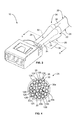
- FIG. 4 is a cross-sectional view of the end 26 of the electrical wire 28 illustrating the end 26 of the electrical wire 28 before the electrical terminal 10 and the electrical wire 28 have been crimped together.
- the electrical wire 28 includes a bundle of the electrical conductors 30 and the electrical insulation layer 36 , which surrounds the bundle of the electrical conductors 30 .
- the electrical wire 28 may include any number of the electrical conductors 30 .
- the electrical conductors 30 of the electrical cable 28 include a group of exterior electrical conductors 30 a that form a perimeter of the bundle of the electrical conductors 30 .
- the electrical conductors 30 include a group of interior electrical conductor 30 b that are surrounded by the exterior electrical conductors 30 b .
- Each electrical conductor 30 includes a metallic surface 126 that defines an exterior surface of the aluminum material of the electrical conductor 30 .
- the electrical conductors 30 also include oxide layers 128 that are formed on the metallic surfaces 126 of the electrical conductors 30 , for example when the electrical conductors 30 are exposed to air. The oxide layers 128 have relatively poor electrical conductivity.
- the oxide layer 128 must be displaced to expose and make physical contact to the metallic surface 126 of the electrical conductor 30 , for example as part of a crimping process.
- the thickness of the oxide layers 128 may be exaggerated in FIG. 4 to better illustrate the oxide layers 128 .
- the actuator 106 is configured to crimp the electrical terminal 10 and the electrical wire 28 together such that the metallic surfaces 126 of at least some of the electrical conductors 30 of the electrical wire 28 form hot weld bonds with the metallic surface(s) 126 of one or more adjacent electrical conductors 30 .
- the bonds between the metallic surfaces 126 are formed through cold welds that form where contact portions of the metallic surfaces 126 come into physical contact with each other, for example by extruding between the oxide layers 128 (if the oxide layers 128 exist).
- Cold welds are solid state bonds formed without fusion between the contact portions of the metallic surfaces 126 that come into physical contact with each other.
- the actuator 106 is configured to crimp the electrical terminal 10 and the electrical wire 28 together such that at least some contact portions of the metallic surfaces 126 of at least some of the electrical conductors 30 form hot weld bonds with one or more contact portions of the metallic surface 126 of one or more adjacent electrical conductors 30 .
- “Hot weld bonds” are liquid state bonds that are formed from a fusion welding process where the contact portions of the metallic surfaces 126 melt and fuse together.
- the actuator 106 may also be configured to crimp the electrical terminal 10 and the electrical wire 28 together such that one or more contact portions of the interior surfaces 40 and/or 42 of the crimp barrel 20 form hot weld bonds with one or more contact portions of the metallic surface 126 of one or more of the exterior electrical conductors 30 a . Any hot weld bonds formed between the crimp barrel 20 and an exterior electrical conductor 30 a provide reliable and sufficient electrical connections between the crimp barrel 20 and the electrical conductors 30 of the electrical wire 28 .
- the actuator 106 is configured to impart sufficient frictional energy between adjacent electrical conductors 30 to cause the hot weld bonds to form by controlling the speed of the movement of the crimp tooling members 108 and 110 relative to each other. Specifically, as the crimp tooling members 108 and 110 press the crimp barrel 20 against the electrical conductors during the crimping operation, the electrical conductors 30 wipe (i.e., slide) against adjacent electrical conductors 30 and the crimp barrel 20 . The wiping displaces and/or breaks open any existing oxide layers 128 of the electrical conductors 30 and thereby exposes the contact portions of the metallic surfaces 126 of the electrical conductors 30 .
- the sliding of the electrical conductors 30 against each other and the crimp barrel 20 during the crimping operation creates frictional forces between adjacent electrical conductors 30 and between the exterior electrical conductors 30 a ( FIGS. 4-6 ) and the crimp barrel 20 .
- a cross-sectional area index reduction as a result of the crimping operation of at least approximately 80% is required to get sufficient extrusion to form a sufficient and reliable electrical connection between the contact portions.
- the speed of the crimp tooling members 108 and 110 controls the amount of frictional energy that is generated by the electrical conductors 30 sliding against each other and the crimp barrel 20 as the crimp barrel 20 is pressed against the electrical conductors 30 . Specifically, the speed of the movement of the crimp tooling members 108 and 110 toward each other determines the duration of time over which the frictional energy is applied to the electrical conductors 30 .
- the actuator 106 is configured to apply the frictional energy to the electrical conductors 30 over a duration of time that is short enough to melt at least some of the contact portions of the metallic surfaces 126 .
- the actuator 106 is configured to move the crimp tooling members 108 and 110 toward each other with a sufficiently high speed such that the frictional forces generate a sufficient amount of heat in the time it takes to form the crimp to cause melting of at least some of the contact portions of the metallic surfaces 126 of the electrical conductors 30 before the generated heat can dissipate along the lengths of the electrical conductors 30 .
- the speed of the movement of the crimp tooling members 108 and 110 toward each other is sufficiently high to generate a quasi-adiabatic condition that melts at least some of the contact portions of the metallic surfaces 126 of the electrical conductors 30 (and/or the contact portions of the surfaces 40 and/or 42 of the crimp barrel 20 ) as the contact portions are formed.
- the actuator 106 provides the relative movement of the crimp tooling members 108 and 110 with a sufficiently high speed to melt at least some of the contact portions of the metallic surfaces 126 and form the hot weld bonds, which prevents the exposed contact portions from forming new oxidation layers thereon at the hot weld bonds.
- the metallic material of the contact portions of the metallic surfaces 126 form the hot weld bonds without any subsequent oxides layer forming between the contact portions at the location of the hot weld bonds.
- the hot weld bonds thus form sufficient and reliable electrical connections because the hot weld bonds are formed between the contact portions of the metallic surfaces 126 (and/or between a contact portion of a metallic surface 126 and a contact portion of an interior surface 40 and/or 42 of the crimp barrel 20 ) without any intervening oxide layers 128 (although some residual oxide material may remain present).
- the crimping operations described and illustrated herein may also form cold welds between some of the contact portions of the metallic surfaces 126 of the electrical conductors 30 (and/or between one or more contact portions of the surfaces 40 and/or 42 of the crimp barrel 20 and one or more contact portions of one or more electrical conductors 30 ) that did not experience enough frictional heat dissipation during the crimping operation to convert from the solid state to the liquid state (i.e., to melt).
- FIGS. 5 and 6 illustrate the hot weld bonds.
- FIG. 5 is a cross-sectional view of the electrical terminal 10 taken along line 5 - 5 of FIG. 2 .
- FIG. 6 is a longitudinal cross-sectional view of the electrical terminal 10 taken through the length of the electrical terminal 10 .
- FIGS. 5 and 6 illustrate the electrical terminal 10 after the crimp barrel 20 has been crimped to the electrical wire 28 .
- the crimping operation has been applied by the actuator 106 ( FIG. 3 ) such that hot weld bonds 130 are formed between at least some of the contact portions 131 of at least some adjacent electrical conductors 30 .
- hot weld bonds 132 are formed between at least some of the contact portions 131 of at least some of the exterior electrical conductors 30 a and the crimp barrel 20 .
- the contact portions 131 of the metallic surfaces 126 of at least some of the interior electrical conductors 30 b have been exposed through the corresponding oxide layer 128 (not visible in FIG. 5 ). At least some of the contact portions 131 have melted formed the hot weld bonds 130 with a contact portion 131 of the metallic surface 126 of one or more adjacent interior electrical conductors 30 b . Moreover, at least some of the contact portions 131 of at least some of the interior electrical conductors 30 b have formed the hot weld bonds 130 with a contact portion 131 of the metallic surface 126 of one or more adjacent exterior electrical conductors 30 a .
- At least some of the contact portions 131 of at least some of the exterior electrical conductors 30 a have formed the hot weld bonds 130 with a contact portion 131 of the metallic surfaces 126 of one or more adjacent exterior electrical conductors 30 a .
- at least some contact portions 133 of the interior surfaces 40 and/or 42 of the crimp barrel 20 have formed the hot weld bonds 132 with at least some contact portions 131 of the metallic surfaces 126 of at least some of the exterior electrical conductors 30 a .
- the weld bonds 130 provide sufficient and reliable electrical connections between the electrical conductors 30 .
- the weld bonds 132 provide sufficient and reliable electrical connections between the electrical conductor 30 and the crimp barrel 20 .
- the electrical conductors 30 of the electrical cable 28 are thus electrically connected to the crimp barrel 20 such that the electrical terminal 10 is electrically connected to the electrical wire 28 .
- the crimp barrel 20 includes the serrations 44 ( FIG. 1 ), which assist in penetrating the oxide layers 128 of the exterior electrical conductors 30 a to facilitate providing (in addition or alternative to the weld bonds 132 ) a sufficient and reliable electrical connection between the exterior electrical conductors 30 a and the crimp barrel 20 .
- the actuator 106 is configured to control the speed of the movement of the crimp tooling members 108 and 110 toward each other to form the hot weld bonds 130 and/or 132 ( FIGS. 5 and 6 ). It should be understood that the speed of the relative movement between the crimp tooling members 108 and 110 is variable along the length of travel of the crimp tooling members 108 and 110 toward each other. Specifically, the crimp tooling members 108 and 110 will be accelerated from a starting position of the crimp tooling members 108 and 110 to an ultimate speed value, and will be decelerated from the ultimate speed value to stop the relative movement at a final crimped position of the crimp tooling members 108 and 110 .
- the actuator 106 may be configured to move the crimp tooling members 108 and 110 toward each other at any ultimate speed value that enables the crimping operation to melt at least some of the contact portions 131 ( FIGS. 5 and 6 ) of the metallic surfaces 126 of at least some of the electrical conductors 30 and form at least some of the hot weld bonds 130 and/or 132 ( FIGS. 5 and 6 ).
- Examples of the ultimate speed value at which the actuator 106 may move the crimp tooling members 108 and 110 toward each other include, but are not limited to, at least approximately 30 meters per second (m/s), at least approximately 40 m/s, at least approximately 45 m/s, at least approximately 50 m/s, and/or the like.
- the ultimate speed value at which the actuator 106 moves the crimp tooling members 108 and 110 toward each other to form the hot weld bonds 130 and/or 132 may each depend on various factors, such as, but not limited to, the coefficient of friction between the components that slide against each other (e.g., two electrical conductors 30 or an electrical conductor 30 and the crimp barrel 20 ), the amount of force required to complete the crimping operation for the particular types of the electrical terminal 10 and the electrical wire 28 , the geometry and/or materials of the crimp barrel 20 , the geometry of the electrical cable 28 , and/or the like.
- the ultimate speed value sufficient to form the hot weld bonds 130 and/or 132 may depend on the length of travel of the movement of the crimp tooling members 108 and 110 toward each other required to complete the crimp, which is determined based on the geometry (e.g., the size and/or shape) of the crimp barrel 20 and/or the electrical cable 28 .
- the actuator 106 may be any type of actuator that enables the actuator 106 to move the crimp tooling members 108 and 110 toward each other along the crimping axis 120 and thereby crimp the electrical terminal 10 and the electrical wire 28 together.
- the actuator 106 is an explosive charge that uses the energy (i.e., explosive forces) generated by the burning of a chemical explosive to move the crimp tooling members 108 and 110 toward each other along the crimping axis 120 .
- the explosive charge may be configured to produce any amount of energy that enables the actuator 106 to provide the ultimate speed value (of the relative movement of the crimp tooling members 108 and 110 ) that enables the crimping operation to form the hot weld bonds 130 and/or 132 .
- the actuator 106 may be configured to apply any amount of force to the crimp tooling members 108 and/or 110 that enables the crimping operation to form the hot weld bonds 130 and/or 132 .
- the spring may be configured to apply any amount of spring force to the crimp tooling members 108 and/or 110 that enables the crimping operation to form the hot weld bonds 130 and/or 132 .
- FIG. 7 is a flowchart of an embodiment of a method 200 for crimping an electrical terminal (e.g., the electrical terminal 10 shown in FIGS. 1-3, 5, and 6 ) to an electrical wire (e.g., the electrical wire 28 shown in FIGS. 2-6 ).
- the method 200 may be performed by a crimp tool, such as, but not limited to, the crimp tool 100 shown in FIG. 3 .
- the method 200 includes positioning, at 202 , the electrical wire and the electrical terminal within a crimp zone (e.g., the crimp zone 118 shown in FIG. 3 ) that extends between opposing crimp tooling members (e.g., the crimp tooling members 108 and 110 shown in FIG.
- a crimp zone e.g., the crimp zone 118 shown in FIG. 3
- opposing crimp tooling members e.g., the crimp tooling members 108 and 110 shown in FIG.
- the electrical wire and the electrical terminal may be assembled together before being positioned at 202 within the crimp zone.
- the electrical terminal and the electrical wire may be separately positioned within the crimp zone, whether at different times and/or simultaneously with each other. Either the electrical wire or the electrical terminal may be positioned within the crimp zone before the other when the electrical terminal and the electrical wire are separately positioned within the crimp zone at different times.
- the method 200 includes pressing a crimp barrel (e.g., the crimp barrel 20 shown in FIGS. 1-3, 5, and 6 ) of the electrical terminal against electrical conductors (e.g., the electrical conductors 30 shown in FIGS. 2-6 ) of the electrical wire using the crimp tooling members such that the electrical conductors are mechanically and electrically connected to the crimp barrel.
- the crimp barrel is pressed at 204 against the electrical conductors such that at least some of the contact portions (e.g., the contact portions 131 shown in FIGS. 5 and 6 ) of the metallic surfaces (e.g., the metallic surfaces 126 shown in FIGS.
- the electrical conductors melt and form hot weld bonds with one or more of the contact portions of the metallic surface of one or more adjacent electrical conductors.
- the metallic surfaces are melted and the hot weld bonds are formed before oxidation layers form on the contact portions at the locations of the hot weld bonds.
- Pressing at 204 the crimp barrel against the electrical conductors includes moving the crimp tooling members toward each other at a speed that is sufficiently high to cause at least some of the contact portions of the metallic surfaces of at least some of the electrical conductors to melt. Moreover, pressing at 204 the crimp barrel against the electrical conductors includes creating, at 204 b , frictional forces between adjacent electrical conductors that generate a sufficient amount of heat to melt at least some of the contact portions of the metallic surfaces of at least some of the electrical conductors.
- pressing at 204 the crimp barrel against the electrical conductors may include wiping, at 204 c , adjacent electrical conductors against each other such that oxide layers of the adjacent electrical conductors are displaced to expose the contact portions of the metallic surfaces of the electrical conductors.
- pressing at 204 the crimp barrel against the electrical conductors comprises melting, at 204 d , a contact portion (e.g., the contact portions 133 shown in FIGS. 5 and 6 ) of a metallic surface (e.g., the surfaces 40 and/or 42 shown in FIGS. 1, 5, and 6 ) of the crimp barrel such that the contact portion of the metallic surface of the crimp barrel forms a hot weld bond with one or more contact portions of the metallic surface of one or more of the electrical conductors.
- a contact portion e.g., the contact portions 133 shown in FIGS. 5 and 6
- a metallic surface e.g., the surfaces 40 and/or 42 shown in FIGS. 1, 5, and 6
- the embodiments described and/or illustrated herein provide a method and apparatus for crimping an electrical terminal to an electrical wire, wherein the crimping operation provides a sufficient and reliable electrical connection between the electrical terminal and the electrical wire.
- the embodiments described and/or illustrated herein may provide a method and apparatus that provides a more sufficient and more reliable electrical connection between an electrical terminal and an electrical wire as compared to at least some known crimping methods and apparatus.
- the embodiments described and/or illustrated herein may provide a method and apparatus that more easily crimps an electrical terminal to an electrical wire as compared to at least some known crimping methods and apparatus.
Priority Applications (9)
| Application Number | Priority Date | Filing Date | Title |
|---|---|---|---|
| US13/871,706 US9520668B2 (en) | 2013-04-26 | 2013-04-26 | Method and apparatus for crimping an electrical terminal to an electrical wire |
| BR112015027046A BR112015027046A2 (pt) | 2013-04-26 | 2014-04-21 | método e aparelho para crimpar um terminal elétrico a um fio elétrico |
| CN201480034866.2A CN105308804B (zh) | 2013-04-26 | 2014-04-21 | 将电端子压接到电线的设备和方法 |
| EP14729124.9A EP2989697B1 (en) | 2013-04-26 | 2014-04-21 | Method and apparatus for crimping an electrical terminal to an electrical wire |
| CA2910116A CA2910116A1 (en) | 2013-04-26 | 2014-04-21 | Method and apparatus for crimping an electrical terminal to an electrical wire |
| MX2015014920A MX353784B (es) | 2013-04-26 | 2014-04-21 | Método y aparato para plegar una terminal eléctrica con un alambre eléctrico. |
| JP2016510713A JP6329251B2 (ja) | 2013-04-26 | 2014-04-21 | 電気端子を電線に圧着する方法 |
| KR1020157033833A KR102109943B1 (ko) | 2013-04-26 | 2014-04-21 | 전기 단자를 전기 와이어에 크림핑하기 위한 방법 및 장치 |
| PCT/US2014/034749 WO2014176145A1 (en) | 2013-04-26 | 2014-04-21 | Method and apparatus for crimping an electrical terminal to an electrical wire |
Applications Claiming Priority (1)
| Application Number | Priority Date | Filing Date | Title |
|---|---|---|---|
| US13/871,706 US9520668B2 (en) | 2013-04-26 | 2013-04-26 | Method and apparatus for crimping an electrical terminal to an electrical wire |
Publications (2)
| Publication Number | Publication Date |
|---|---|
| US20140317922A1 US20140317922A1 (en) | 2014-10-30 |
| US9520668B2 true US9520668B2 (en) | 2016-12-13 |
Family
ID=50897895
Family Applications (1)
| Application Number | Title | Priority Date | Filing Date |
|---|---|---|---|
| US13/871,706 Active 2035-03-25 US9520668B2 (en) | 2013-04-26 | 2013-04-26 | Method and apparatus for crimping an electrical terminal to an electrical wire |
Country Status (9)
| Country | Link |
|---|---|
| US (1) | US9520668B2 (pt) |
| EP (1) | EP2989697B1 (pt) |
| JP (1) | JP6329251B2 (pt) |
| KR (1) | KR102109943B1 (pt) |
| CN (1) | CN105308804B (pt) |
| BR (1) | BR112015027046A2 (pt) |
| CA (1) | CA2910116A1 (pt) |
| MX (1) | MX353784B (pt) |
| WO (1) | WO2014176145A1 (pt) |
Cited By (4)
| Publication number | Priority date | Publication date | Assignee | Title |
|---|---|---|---|---|
| US20160233637A1 (en) * | 2015-02-11 | 2016-08-11 | Md Elektronik Gmbh | Method and device for producing a cable and cable produced by the method |
| US20190165492A1 (en) * | 2017-11-30 | 2019-05-30 | Yazaki Corporation | Terminal connecting method and terminal |
| US11139592B2 (en) * | 2017-11-24 | 2021-10-05 | Yazaki Corporation | Terminal connecting method |
| US11791599B2 (en) | 2017-12-28 | 2023-10-17 | Autonetworks Technologies, Ltd. | Electric cable with terminal and method for manufacturing electric cable with terminal |
Families Citing this family (14)
| Publication number | Priority date | Publication date | Assignee | Title |
|---|---|---|---|---|
| US10361527B2 (en) | 2015-02-25 | 2019-07-23 | Te Connectivity Corporation | Electrical terminal and device for forming a terminal |
| DE102015219701A1 (de) * | 2015-10-12 | 2017-04-13 | Md Elektronik Gmbh | Verfahren zum Herstellen einer elektrischen Verbindung zwischen zwei elektrisch leitfähigen Komponenten und eine Crimpvorrichtung |
| JP6326035B2 (ja) * | 2015-12-16 | 2018-05-16 | 矢崎総業株式会社 | 圧着端子 |
| JP6423783B2 (ja) * | 2015-12-16 | 2018-11-14 | 矢崎総業株式会社 | 圧着端子 |
| JP6307059B2 (ja) * | 2015-12-16 | 2018-04-04 | 矢崎総業株式会社 | 圧着端子 |
| JP6254567B2 (ja) * | 2015-12-16 | 2017-12-27 | 矢崎総業株式会社 | 圧着端子及び端子圧着装置 |
| JP6367785B2 (ja) * | 2015-12-16 | 2018-08-01 | 矢崎総業株式会社 | 端子付き電線及び端子圧着装置 |
| US10355437B2 (en) * | 2016-11-02 | 2019-07-16 | Te Connectivity Corporation | Terminal crimping machine including an electrical crimp consolidation circuit |
| CN106450868B (zh) | 2016-11-04 | 2019-03-26 | 吉林省中赢高科技有限公司 | 一种铝端子和铜铝过渡连接器 |
| CN107104292A (zh) * | 2017-06-05 | 2017-08-29 | 吉林省中赢高科技有限公司 | 一种铜端子与铝导线的接头及其电阻焊接方法 |
| CN107342466B (zh) * | 2017-06-05 | 2019-07-16 | 吉林省中赢高科技有限公司 | 一种铜端子与铝导线的接头及其超声波焊接方法 |
| DE102017218486A1 (de) * | 2017-10-16 | 2019-04-18 | Te Connectivity Germany Gmbh | Verfahren und Anordnung zum Herstellen einer gecrimpten Verbindungsanordnung, Verbindungsanordnung |
| CN109921200A (zh) * | 2017-12-12 | 2019-06-21 | 泰科电子(上海)有限公司 | 端子及其制造方法和通过该端子电连接导线和多个电缆的方法 |
| JP7357446B2 (ja) | 2018-12-19 | 2023-10-06 | 矢崎総業株式会社 | 端子付電線及びその製造方法 |
Citations (23)
| Publication number | Priority date | Publication date | Assignee | Title |
|---|---|---|---|---|
| US3251216A (en) | 1963-06-21 | 1966-05-17 | Amp Inc | Method and apparatus for applying electrical connectors to conductors |
| US3612748A (en) | 1969-05-21 | 1971-10-12 | Ideal Ind | Explosion connector |
| US3878318A (en) | 1973-01-02 | 1975-04-15 | Amp Inc | Aluminum electrical connection |
| US3955044A (en) | 1970-12-03 | 1976-05-04 | Amp Incorporated | Corrosion proof terminal for aluminum wire |
| US4142771A (en) | 1974-10-16 | 1979-03-06 | Amp Incorporated | Crimp-type terminal |
| US4932906A (en) | 1988-12-16 | 1990-06-12 | Amp Incorporated | Electrical contact terminal |
| US5532433A (en) | 1991-11-13 | 1996-07-02 | Yazaki Corporation | Waterproof-type terminal connection structure and method of producing same |
| US5561267A (en) | 1993-11-30 | 1996-10-01 | Sumitomo Wiring Systems, Ltd. | Crimp terminal and process for producing the same |
| US5852868A (en) * | 1994-08-05 | 1998-12-29 | The Whitaker Corporation | Machine including a plurality of crimping stations for preparing electrical harnesses |
| EP0944130A2 (en) | 1998-03-19 | 1999-09-22 | Framatome Connectors International | Crimp connection |
| US5966806A (en) * | 1996-06-12 | 1999-10-19 | Yazaki Corporation | Control method of terminal crimping device |
| US20040029454A1 (en) * | 2002-08-07 | 2004-02-12 | Yazaki Corporation | Method of connecting wire and terminal fitting |
| US7048562B2 (en) | 2004-07-13 | 2006-05-23 | Yazaki Europe Ltd. | Connection between a cable end piece and a cable end |
| US20070155235A1 (en) | 2004-01-27 | 2007-07-05 | Mark De Keyser | Crimped electric contact with a closed barrel, method of crimping such a contact, and corresponding crimping tool |
| US7306495B2 (en) | 2003-07-30 | 2007-12-11 | The Furukawa Electric Co., Ltd. | Terminal crimping structure and terminal crimping method onto aluminum electric-wire and producing method of aluminum electric-wire with terminal |
| JP2010049941A (ja) | 2008-08-21 | 2010-03-04 | Sumitomo Wiring Syst Ltd | 電線と端子金具との接続構造 |
| CN201455038U (zh) * | 2009-08-11 | 2010-05-12 | 禹州市电力工业公司 | 导线压接器 |
| US20100144189A1 (en) | 2008-12-09 | 2010-06-10 | Yazaki Corporation | Crimping terminal |
| US7775842B2 (en) | 2007-12-21 | 2010-08-17 | Tyco Electronics Japan G. K. | Crimping structure and crimping method |
| US20110094797A1 (en) * | 2008-11-19 | 2011-04-28 | Autonetworks Technologies, Ltd. | Electric wire with terminal connector and method of manufacturing electric wire with terminal connector |
| US7938694B2 (en) | 2007-03-29 | 2011-05-10 | Autonetworks Technologies, Ltd. | Connector terminal and connector with the connector terminal |
| WO2011125348A1 (ja) | 2010-04-01 | 2011-10-13 | 住友電装株式会社 | 端子圧着電線の製造方法、端子圧着電線及び端子圧着装置 |
| US20130059487A1 (en) * | 2010-04-12 | 2013-03-07 | Fci Automotive Holding | Electrical Contact Terminal with Improved Connection Portion |
Family Cites Families (1)
| Publication number | Priority date | Publication date | Assignee | Title |
|---|---|---|---|---|
| JPH09167640A (ja) * | 1995-12-14 | 1997-06-24 | Asahi Electric Works Ltd | 電線の平行継手の爆発接合方法 |
-
2013
- 2013-04-26 US US13/871,706 patent/US9520668B2/en active Active
-
2014
- 2014-04-21 MX MX2015014920A patent/MX353784B/es active IP Right Grant
- 2014-04-21 WO PCT/US2014/034749 patent/WO2014176145A1/en active Application Filing
- 2014-04-21 CA CA2910116A patent/CA2910116A1/en not_active Abandoned
- 2014-04-21 EP EP14729124.9A patent/EP2989697B1/en active Active
- 2014-04-21 KR KR1020157033833A patent/KR102109943B1/ko active IP Right Grant
- 2014-04-21 BR BR112015027046A patent/BR112015027046A2/pt not_active IP Right Cessation
- 2014-04-21 CN CN201480034866.2A patent/CN105308804B/zh active Active
- 2014-04-21 JP JP2016510713A patent/JP6329251B2/ja active Active
Patent Citations (23)
| Publication number | Priority date | Publication date | Assignee | Title |
|---|---|---|---|---|
| US3251216A (en) | 1963-06-21 | 1966-05-17 | Amp Inc | Method and apparatus for applying electrical connectors to conductors |
| US3612748A (en) | 1969-05-21 | 1971-10-12 | Ideal Ind | Explosion connector |
| US3955044A (en) | 1970-12-03 | 1976-05-04 | Amp Incorporated | Corrosion proof terminal for aluminum wire |
| US3878318A (en) | 1973-01-02 | 1975-04-15 | Amp Inc | Aluminum electrical connection |
| US4142771A (en) | 1974-10-16 | 1979-03-06 | Amp Incorporated | Crimp-type terminal |
| US4932906A (en) | 1988-12-16 | 1990-06-12 | Amp Incorporated | Electrical contact terminal |
| US5532433A (en) | 1991-11-13 | 1996-07-02 | Yazaki Corporation | Waterproof-type terminal connection structure and method of producing same |
| US5561267A (en) | 1993-11-30 | 1996-10-01 | Sumitomo Wiring Systems, Ltd. | Crimp terminal and process for producing the same |
| US5852868A (en) * | 1994-08-05 | 1998-12-29 | The Whitaker Corporation | Machine including a plurality of crimping stations for preparing electrical harnesses |
| US5966806A (en) * | 1996-06-12 | 1999-10-19 | Yazaki Corporation | Control method of terminal crimping device |
| EP0944130A2 (en) | 1998-03-19 | 1999-09-22 | Framatome Connectors International | Crimp connection |
| US20040029454A1 (en) * | 2002-08-07 | 2004-02-12 | Yazaki Corporation | Method of connecting wire and terminal fitting |
| US7306495B2 (en) | 2003-07-30 | 2007-12-11 | The Furukawa Electric Co., Ltd. | Terminal crimping structure and terminal crimping method onto aluminum electric-wire and producing method of aluminum electric-wire with terminal |
| US20070155235A1 (en) | 2004-01-27 | 2007-07-05 | Mark De Keyser | Crimped electric contact with a closed barrel, method of crimping such a contact, and corresponding crimping tool |
| US7048562B2 (en) | 2004-07-13 | 2006-05-23 | Yazaki Europe Ltd. | Connection between a cable end piece and a cable end |
| US7938694B2 (en) | 2007-03-29 | 2011-05-10 | Autonetworks Technologies, Ltd. | Connector terminal and connector with the connector terminal |
| US7775842B2 (en) | 2007-12-21 | 2010-08-17 | Tyco Electronics Japan G. K. | Crimping structure and crimping method |
| JP2010049941A (ja) | 2008-08-21 | 2010-03-04 | Sumitomo Wiring Syst Ltd | 電線と端子金具との接続構造 |
| US20110094797A1 (en) * | 2008-11-19 | 2011-04-28 | Autonetworks Technologies, Ltd. | Electric wire with terminal connector and method of manufacturing electric wire with terminal connector |
| US20100144189A1 (en) | 2008-12-09 | 2010-06-10 | Yazaki Corporation | Crimping terminal |
| CN201455038U (zh) * | 2009-08-11 | 2010-05-12 | 禹州市电力工业公司 | 导线压接器 |
| WO2011125348A1 (ja) | 2010-04-01 | 2011-10-13 | 住友電装株式会社 | 端子圧着電線の製造方法、端子圧着電線及び端子圧着装置 |
| US20130059487A1 (en) * | 2010-04-12 | 2013-03-07 | Fci Automotive Holding | Electrical Contact Terminal with Improved Connection Portion |
Non-Patent Citations (2)
| Title |
|---|
| International Search Report, International Application No. PCT/US2014/034749, International Filing Date, Apr. 21, 2014. |
| ISR for PCT/US2011/001754 dated Oct. 14, 2011. |
Cited By (5)
| Publication number | Priority date | Publication date | Assignee | Title |
|---|---|---|---|---|
| US20160233637A1 (en) * | 2015-02-11 | 2016-08-11 | Md Elektronik Gmbh | Method and device for producing a cable and cable produced by the method |
| US9997885B2 (en) * | 2015-02-11 | 2018-06-12 | Md Elektronik Gmbh | Method and device for producing a cable and cable produced by the method |
| US11139592B2 (en) * | 2017-11-24 | 2021-10-05 | Yazaki Corporation | Terminal connecting method |
| US20190165492A1 (en) * | 2017-11-30 | 2019-05-30 | Yazaki Corporation | Terminal connecting method and terminal |
| US11791599B2 (en) | 2017-12-28 | 2023-10-17 | Autonetworks Technologies, Ltd. | Electric cable with terminal and method for manufacturing electric cable with terminal |
Also Published As
| Publication number | Publication date |
|---|---|
| KR20160007543A (ko) | 2016-01-20 |
| WO2014176145A1 (en) | 2014-10-30 |
| JP6329251B2 (ja) | 2018-05-23 |
| EP2989697B1 (en) | 2018-06-06 |
| CN105308804B (zh) | 2018-03-16 |
| US20140317922A1 (en) | 2014-10-30 |
| MX353784B (es) | 2018-01-29 |
| CN105308804A (zh) | 2016-02-03 |
| JP2016517156A (ja) | 2016-06-09 |
| BR112015027046A2 (pt) | 2017-07-25 |
| CA2910116A1 (en) | 2014-10-30 |
| EP2989697A1 (en) | 2016-03-02 |
| KR102109943B1 (ko) | 2020-05-13 |
| MX2015014920A (es) | 2016-12-15 |
Similar Documents
| Publication | Publication Date | Title |
|---|---|---|
| US9520668B2 (en) | Method and apparatus for crimping an electrical terminal to an electrical wire | |
| US9601840B2 (en) | Terminal connection strip, method of manufacturing crimp terminal, wire crimping device, and method of crimping wire | |
| JP5607858B1 (ja) | 電線接続構造体の製造方法および電線接続構造体 | |
| US10361527B2 (en) | Electrical terminal and device for forming a terminal | |
| EP2961011B1 (en) | Crimped terminal and production method for crimped terminals | |
| CN105261911B (zh) | 绞合线的接通方法 | |
| JP2013004411A (ja) | 電線の接続構造および接続方法 | |
| WO2011125348A1 (ja) | 端子圧着電線の製造方法、端子圧着電線及び端子圧着装置 | |
| EP2764129B1 (en) | Crimped terminal | |
| KR20190138749A (ko) | 다중 버스형 종단부들 | |
| EP3262659B1 (en) | Electrical wire with conductive particles | |
| US3800584A (en) | Electrical connection having radial crimp and axial indentation | |
| EP3588679B1 (en) | Crimp and method for producing a crimp | |
| JP6452344B2 (ja) | 圧着端子、接続構造体、コネクタ、ワイヤーハーネス、並びに圧着端子の製造方法及び接続構造体の製造方法 | |
| JP6007125B2 (ja) | 電線接続構造体の製造方法 | |
| WO2021241294A1 (ja) | 端子、および端子付き電線 | |
| JP5535287B2 (ja) | 接続構造体の製造方法、接続構造体、コネクタ、ワイヤハーネス | |
| JP5011173B2 (ja) | 端子圧着装置、及びワイヤーハーネスの製造方法 | |
| JP2006007294A (ja) | 通電熱カシメ接合方法と装置 | |
| DE2415675A1 (de) | Verfahren und werkzeug zum verbinden eines leiters mit einer anschlussklemme |
Legal Events
| Date | Code | Title | Description |
|---|---|---|---|
| AS | Assignment |
Owner name: TYCO ELECTRONICS CORPORATION, PENNSYLVANIA Free format text: ASSIGNMENT OF ASSIGNORS INTEREST;ASSIGNORS:SCHMIDT, HELGE;KARRASCH, CHRISTOPHER J.;MYERS, MARJORIE KAY;REEL/FRAME:030299/0517 Effective date: 20130426 Owner name: TYCO ELECTRONICS AMP GMBH, GERMANY Free format text: ASSIGNMENT OF ASSIGNORS INTEREST;ASSIGNORS:SCHMIDT, HELGE;KARRASCH, CHRISTOPHER J.;MYERS, MARJORIE KAY;REEL/FRAME:030299/0517 Effective date: 20130426 |
|
| AS | Assignment |
Owner name: TE CONNECTIVITY GERMANY GMBH, GERMANY Free format text: CHANGE OF NAME;ASSIGNOR:TYCO ELECTRONICS AMP GMBH;REEL/FRAME:036617/0856 Effective date: 20150630 |
|
| STCF | Information on status: patent grant |
Free format text: PATENTED CASE |
|
| AS | Assignment |
Owner name: TE CONNECTIVITY CORPORATION, PENNSYLVANIA Free format text: CHANGE OF NAME;ASSIGNOR:TYCO ELECTRONICS CORPORATION;REEL/FRAME:041350/0085 Effective date: 20170101 |
|
| MAFP | Maintenance fee payment |
Free format text: PAYMENT OF MAINTENANCE FEE, 4TH YEAR, LARGE ENTITY (ORIGINAL EVENT CODE: M1551); ENTITY STATUS OF PATENT OWNER: LARGE ENTITY Year of fee payment: 4 |