US7775842B2 - Crimping structure and crimping method - Google Patents
Crimping structure and crimping method Download PDFInfo
- Publication number
- US7775842B2 US7775842B2 US12/339,806 US33980608A US7775842B2 US 7775842 B2 US7775842 B2 US 7775842B2 US 33980608 A US33980608 A US 33980608A US 7775842 B2 US7775842 B2 US 7775842B2
- Authority
- US
- United States
- Prior art keywords
- crimping
- conductor
- crimping part
- barrel
- conductors
- Prior art date
- Legal status (The legal status is an assumption and is not a legal conclusion. Google has not performed a legal analysis and makes no representation as to the accuracy of the status listed.)
- Active
Links
- 238000002788 crimping Methods 0.000 title claims abstract description 164
- 238000000034 method Methods 0.000 title claims description 8
- 239000004020 conductor Substances 0.000 claims abstract description 141
- 230000006835 compression Effects 0.000 description 23
- 238000007906 compression Methods 0.000 description 23
- 230000002349 favourable effect Effects 0.000 description 7
- 238000009413 insulation Methods 0.000 description 6
- 238000005452 bending Methods 0.000 description 5
- 238000007796 conventional method Methods 0.000 description 3
- 229910052751 metal Inorganic materials 0.000 description 3
- 239000002184 metal Substances 0.000 description 3
- RYGMFSIKBFXOCR-UHFFFAOYSA-N Copper Chemical compound [Cu] RYGMFSIKBFXOCR-UHFFFAOYSA-N 0.000 description 2
- 229910052782 aluminium Inorganic materials 0.000 description 2
- XAGFODPZIPBFFR-UHFFFAOYSA-N aluminium Chemical compound [Al] XAGFODPZIPBFFR-UHFFFAOYSA-N 0.000 description 2
- 238000010276 construction Methods 0.000 description 2
- 238000010586 diagram Methods 0.000 description 2
- 238000003780 insertion Methods 0.000 description 2
- 230000037431 insertion Effects 0.000 description 2
- 230000013011 mating Effects 0.000 description 2
- 230000004075 alteration Effects 0.000 description 1
- 230000000977 initiatory effect Effects 0.000 description 1
- 238000004519 manufacturing process Methods 0.000 description 1
- 230000000750 progressive effect Effects 0.000 description 1
- 238000005476 soldering Methods 0.000 description 1
- 230000001502 supplementing effect Effects 0.000 description 1
Images


Classifications
-
- H—ELECTRICITY
- H01—ELECTRIC ELEMENTS
- H01R—ELECTRICALLY-CONDUCTIVE CONNECTIONS; STRUCTURAL ASSOCIATIONS OF A PLURALITY OF MUTUALLY-INSULATED ELECTRICAL CONNECTING ELEMENTS; COUPLING DEVICES; CURRENT COLLECTORS
- H01R43/00—Apparatus or processes specially adapted for manufacturing, assembling, maintaining, or repairing of line connectors or current collectors or for joining electric conductors
- H01R43/04—Apparatus or processes specially adapted for manufacturing, assembling, maintaining, or repairing of line connectors or current collectors or for joining electric conductors for forming connections by deformation, e.g. crimping tool
- H01R43/058—Crimping mandrels
-
- H—ELECTRICITY
- H01—ELECTRIC ELEMENTS
- H01R—ELECTRICALLY-CONDUCTIVE CONNECTIONS; STRUCTURAL ASSOCIATIONS OF A PLURALITY OF MUTUALLY-INSULATED ELECTRICAL CONNECTING ELEMENTS; COUPLING DEVICES; CURRENT COLLECTORS
- H01R4/00—Electrically-conductive connections between two or more conductive members in direct contact, i.e. touching one another; Means for effecting or maintaining such contact; Electrically-conductive connections having two or more spaced connecting locations for conductors and using contact members penetrating insulation
- H01R4/10—Electrically-conductive connections between two or more conductive members in direct contact, i.e. touching one another; Means for effecting or maintaining such contact; Electrically-conductive connections having two or more spaced connecting locations for conductors and using contact members penetrating insulation effected solely by twisting, wrapping, bending, crimping, or other permanent deformation
- H01R4/18—Electrically-conductive connections between two or more conductive members in direct contact, i.e. touching one another; Means for effecting or maintaining such contact; Electrically-conductive connections having two or more spaced connecting locations for conductors and using contact members penetrating insulation effected solely by twisting, wrapping, bending, crimping, or other permanent deformation by crimping
- H01R4/183—Electrically-conductive connections between two or more conductive members in direct contact, i.e. touching one another; Means for effecting or maintaining such contact; Electrically-conductive connections having two or more spaced connecting locations for conductors and using contact members penetrating insulation effected solely by twisting, wrapping, bending, crimping, or other permanent deformation by crimping for cylindrical elongated bodies, e.g. cables having circular cross-section
- H01R4/184—Electrically-conductive connections between two or more conductive members in direct contact, i.e. touching one another; Means for effecting or maintaining such contact; Electrically-conductive connections having two or more spaced connecting locations for conductors and using contact members penetrating insulation effected solely by twisting, wrapping, bending, crimping, or other permanent deformation by crimping for cylindrical elongated bodies, e.g. cables having circular cross-section comprising a U-shaped wire-receiving portion
- H01R4/185—Electrically-conductive connections between two or more conductive members in direct contact, i.e. touching one another; Means for effecting or maintaining such contact; Electrically-conductive connections having two or more spaced connecting locations for conductors and using contact members penetrating insulation effected solely by twisting, wrapping, bending, crimping, or other permanent deformation by crimping for cylindrical elongated bodies, e.g. cables having circular cross-section comprising a U-shaped wire-receiving portion combined with a U-shaped insulation-receiving portion
Definitions
- a crimp connection is widely used in connecting a terminal and a conductor, for instance a core wire of an electrical wire, because the connection can be performed without soldering. Therefore, the connection is suitable for mass production using automated equipment.
- the barrel around the conductor is compressed and deformed by a crimping tool.
- the conductor is placed in a state of compression at a specified compressibility (compression ratio) by the barrel.
- the compressibility of the conductor by the barrel is determined based on the electrical characteristics and mechanical characteristics at the crimping part.
- the compression ratio of the conductor that is favorable for the electrical characteristics and mechanical characteristics do not generally match at the crimping part of the terminal.
- the compression ration that is favorable for the electrical characteristics means the compressibility of the conductor at which the electrical resistance of the crimping part is at the minimum.
- the compressibility of the conductor that is favorable for the mechanical characteristics means the compressibility of the conductor at which the tensile strength of the crimping part is at the maximum.
- the compressibility of the conductor indicates the ratio of the cross-sectional area of the conductor prior to crimping to the cross-sectional area of the conductor following the crimping, and means that the higher the compressibility, the higher the amount of compression (same below).
- the compressibility of the conductor crimped to an open crimp barrel is controlled by the height of the open crimp barrel compressed by a crimping tool (crimping height).
- the electrical resistance of the crimping part is reduced due to the breakage of an oxide film formed on the surface of the conductor or the like.
- the compressibility of the conductor becomes excessively high, the electrical resistance of the crimping part is increased, resulting from a reduction in the cross-sectional area of the conductor at the crimping part.
- the tensile strength of the crimping part is increased.
- the compressibility of the conductor becomes excessively high, the tensile strength of the crimping part is reduced, resulting from a reduction in the cross-sectional area of the conductor at the crimping part.
- the compressibility of the conductor that is favorable for the electrical characteristics is generally higher than the compressibility of the conductor that is favorable for the mechanical characteristics.
- An aluminum wire in particular, has lower mechanical strength than a copper wire, and an oxide film tends to be formed on the surface thereof. Accordingly, in cases where an aluminum wire and a terminal are connected by crimping, the discrepancy between the compressibility of the conductor that is favorable for the electrical characteristics and the compressibility of the conductor that is favorable for the mechanical characteristics is increased compared to the case of a copper wire.
- the present invention is made in view of the technical problem described above, and it is an object of the present invention, among others, to provide a crimping structure and a crimping method that can optimize both the electrical characteristics and mechanical characteristics at the crimping part of a terminal.
- a crimping structure for a conductor is provided using a crimp barrel, wherein the crimp barrel has a plurality of crimping parts that are provided continuously along an axial direction of the conductor.
- the crimp barrel is formed such that the widths of the plurality of crimping parts are different from each other in the expanded state, and the plurality of crimping parts are all compressed to a uniform height along the axial direction.
- the second crimping part is formed toward the tip end of the conductor relative to the first crimping part, and the open crimp barrel is formed such that the width of the second crimping part is greater than the width of the first crimping part in the expanded state.
- the first crimping part and the second crimping part are both compressed to a uniform height along the axial direction of the conductor by a paired anvil and crimper.
- FIG. 1 is a perspective view of a female-type terminal according to an embodiment of the present invention, shown together with covered electrical conductors;
- FIG. 2 is a plan view of the female-type terminal shown in FIG. 1 ;
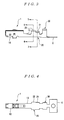
- FIG. 3 is a side view of the female-type terminal shown in FIG. 1 ;
- FIG. 4 is a bottom view of the female-type terminal shown in FIG. 1 ;
- FIG. 5 is a plan view showing the expanded state of the female-type terminal shown in FIG. 1 ;
- FIG. 6 is a sectional view along line 6 - 6 in FIG. 3 ;
- FIG. 7 is a sectional view along line 7 - 7 in FIG. 3 ;
- FIGS. 8 a - 8 d 2 are model diagrams showing progressive states during the crimping of conductors to the crimping part of the female-type terminal shown in FIG. 1 using a crimping tool.
- FIG. 1 is a perspective view of a female-type terminal according to an embodiment of the present invention, shown together with covered electrical conductors.
- FIG. 2 is a plan view of the female-type terminal shown in FIG. 1 .
- FIG. 3 is a side view of the female-type terminal shown in FIG. 1 .
- FIG. 4 is a bottom view of the female-type terminal shown in FIG. 1 .
- FIG. 5 is a plan view showing the expanded state of the female-type terminal shown in FIG. 1 .
- FIG. 6 is a sectional view along line 6 - 6 in FIG. 3 .
- FIG. 7 is a sectional view along line 7 - 7 in FIG. 3 .
- FIG. 8 is a model diagram showing states during the crimping of conductors to the crimping part of the female-type terminal shown in FIG. 1 using a crimping tool. Note that in FIGS. 1 through 7 , the direction in which the conductors Wa of covered electrical conductors W extend is designated as the forward-rearward direction, with the side of the conductors Wa toward a mating contact (toward a receptacle 10 ) being referred to as forward.
- the crimping structure of the present invention can be applied to various terminals having an open crimp barrel that crimps a conductor. Furthermore, the crimping structure of the present invention can be applied to an open crimp barrel that crimps a conductor.
- An open crimp barrel is widely used as the crimping part of a terminal, because it is suitable for work by means of automated equipment.
- the wiring (wire harness) of an automobile comprises numerous electrical conductors, automated equipment-based work must inevitably be presumed.
- an insulation barrel in the wiring of an automobile, it is necessary to increase the holding force by installing an insulation barrel in order to prevent damage to the core conductors (wires) caused by vibration accompanying driving to the maximum extent possible. Accordingly, an open crimp barrel is utilized particularly as a terminal for automotive use.
- the female-type terminal 1 shown in FIGS. 1 through 4 , has a base 13 , a receptacle 10 that extends forward from the base 13 , and a main barrel 15 that extends rearward from the base 13 .
- the female-type terminal 1 is formed by bending a stamped metal plate.
- the female-type terminal 1 which is in a state prior to the bending work (hereinafter referred to as “expanded state”), is a flat plate form as shown in FIG. 5 .
- the receptacle 10 is formed by bending a stamped metal plate into a box shape as shown in FIGS. 1 through 4 .
- the receptacle 10 has a terminal insertion opening 11 into which the male-type terminal (not shown in the figures) of a mating connector is inserted. Furthermore, the receptacle 10 is electrically connected to the male-type terminal that is inserted into the terminal insertion opening 11 .
- the main barrel 15 is formed as an open crimp barrel, and crimps the covered electrical conductors Wa, of cable W.
- the main barrel 15 has a conductor barrel 20 that crimps the conductors Wa, and an insulation barrel 30 that crimps the insulating covering Wb of the cable W.
- the conductor barrel 20 is formed by bending a stamped metal plate such that the section as seen from the forward-rearward direction (the left-right direction in FIGS. 2 through 4 and the depth direction in FIGS. 6 and 7 ) is in the shape of the letter U. Furthermore, the conductor barrel 20 is composed of a first crimping part 21 and a second crimping part 22 that are formed in a continuous manner along the forward-rearward direction.
- the second crimping part 22 is formed toward the tip ends of the conductors Wa relative to the first crimping part 21 .
- the conductor barrel 20 of the female-type terminal 1 is formed such that the width of the first crimping part 21 and the width of the second crimping part 22 are different from each other in the expanded state.
- the conductor barrel 20 of the female-type terminal 1 is formed such that the width of the second crimping part 22 is greater than the width of the first crimping part 21 in the expanded state.
- the conductor barrel 20 of the female-type terminal 1 is formed such that the two sides of the first crimping part 21 in the direction of width (vertical direction in FIG.
- the conductor barrel 20 of the female-type terminal 1 is formed such that the two sides of the second crimping part 22 in the direction of width extend parallel to each other along the forward-rearward direction in the expanded state. That is, the conductor barrel 20 of the female-type terminal 1 is formed such that each of the two sides of the conductor barrel 20 in the direction of width creates a staircase shape along the forward-rearward direction in the expanded state, with one side of the first crimping part 21 in the direction of width and one side of the second crimping part 22 in the direction of width. Consequently, as is shown in FIG.
- the conductor barrel 20 of the female-type terminal 1 formed by the bending work, is such that the respective end portions in the direction of width of the second crimping part 22 protrude diagonally upward, relative to the respective end portions in the direction of width of the first crimping part 21 .
- the insulation barrel 30 is formed such that the section as seen from the forward-rearward direction is in the shape of the letter U as shown in FIG. 1 .
- FIGS. 1 through 5 show a state in which the female-type terminal 1 is connected to a contact carrier C, but the female-type terminal 1 is cut off from the contact carrier C following working.
- a crimping tool 40 for crimping the conductor barrel 20 of the female-type terminal 1 to the conductors Wa of the covered cable W will be described.
- the crimping tool 40 comprises an anvil 41 that positions and holds the female-type terminal 1 , and a crimper 42 that compresses, from above, the conductor barrel 20 of the female-type terminal 1 held by the anvil 41 .
- the compression surfaces of the anvil 41 and crimper 42 that contact the conductor barrel 20 may be flat over the forward-rearward direction of the female-type terminal 1 .
- a placement groove 43 in which the female-type terminal 1 is installed is formed in the upper surface of the anvil 41 .
- the placement groove 43 has a U-shaped section that fits the back surface of the conductor barrel 20 .
- the placement groove 43 is formed along the forward-rearward direction. Note that the forward-rearward direction is the depth direction in FIG. 8 .
- the anvil 41 holds, from below, the bottom surface of the conductor barrel 20 of the female-type terminal 1 installed in the placement groove 43 .
- the crimper 42 is designed to be movable in a receiving or separating direction with respect to the anvil 41 , which is installed in a fixed manner. In the present embodiment, the crimper 42 can move in the vertical direction.
- a compression groove 44 which mutually faces a placement groove 43 in the anvil 41 , is formed in the undersurface of the crimper 42 , as shown in FIGS. 8 a - 8 d 2 .
- the compression groove 44 extends parallel to the placement groove 43 in the anvil 41 .
- the compression groove 44 is formed such that the section as seen, from the forward-rearward direction, is in the shape of the letter M.
- the compression groove 44 compresses the conductor barrel 20 of the female-type terminal 1 , having been positioned in the placement groove 43 of the anvil 41 .
- the crimping of the conductor barrel 20 of the female-type terminal 1 to the conductors Wa of the covered electrical conductors W will be described.
- the crimping of the conductors Wa to the conductor barrel 20 and the crimping of the insulating covering Wb to the insulation barrel 30 are performed at the same time.
- the crimping of the insulating covering Wb to the insulation barrel 30 will be omitted from the description.
- the insulating covering Wb, at the tip end portions of the cable W is removed in advance, so that the conductors Wa are exposed.
- FIG. 8 a shows the crimping tool 40 in the initial state of crimping, wherein the crimper 42 is positioned above the anvil 41 .
- the female-type terminal 1 When the conductor barrel 20 of the female-type terminal 1 is to be crimped to the conductors Wa of the cable W, the female-type terminal 1 is first positioned in the placement groove 43 of the anvil 41 , the crimping tool 40 set in the initial state. Furthermore, the conductors Wa are inserted into the conductor barrel 20 of the female-type terminal 1 .
- the crimper 42 is lowered toward the anvil 41 , thus initiating the compressive deformation of the conductor barrel 20 by means of the anvil 41 and crimper 42 .
- the first crimping part 21 and the second crimping part 22 of the conductor barrel 20 are compressively deformed simultaneously by the paired anvil 41 and crimper 42 .
- both end portions of the first crimping part 21 and the second crimping part 22 of the conductor barrel 20 are respectively deformed along the inner surfaces of the compression groove 44 of the anvil 41 .
- FIG. 8 c shows further lowering of the crimper 42 .
- Both end portions of the first crimping part 21 and both end portions in the direction of width of the second crimping part 22 of the conductor barrel 20 are respectively bent downward along the bottom surface of the compression groove 44 in the crimper 42 .
- first crimping part 21 and second crimping part 22 are respectively deformed so as to surround the conductors Wa. Moreover, both end portions of the first crimping part 21 and the second crimping part 22 of the conductor barrel 20 compress, in the direction of width, the cable W inserted into the conductor barrel 20 . Then, as a result of the first crimping part 21 and second crimping part 22 compressing the cable W, which has been inserted into the conductor barrel 20 , the gap between the conductors Wa and the gap between the conductor barrel 20 and the conductors Wa is closed.
- the conductor barrel 20 is compressed to a specified height (crimping height) a, as shown in FIGS. 8 d 1 and 8 d 2 , by lowering the crimper 42 , the crimping of the conductor barrel 20 to the conductors Wa is completed.
- the first crimping part 21 and the second crimping part 22 of the conductor barrel 20 are both compressed to the uniform height ⁇ , along the forward-rearward direction.
- the first crimping part 21 and second crimping part 22 which have different widths from each other in the expanded state, are compressed simultaneously (in a single compression step) until both of these crimping parts are made to have the same height ⁇ by the paired anvil 41 and crimper 42 .
- the conductor barrel 20 of the female-type terminal 1 is formed such that the width of the second crimping part 22 is greater than the width of the first crimping part 21 in the expanded state.
- the amount of compression by the end portions of the second crimping part 22 on the conductors Wa becomes greater than the amount of compression applied to the conductors Wa by the end portions of the first crimping part 21 . Accordingly, in the conductor barrel 20 that has crimped the conductors Wa (i.e., in the crimping structure), the amount of compression of the conductors Wa by the second crimping part 22 is greater than the amount of compression of the conductors Wa by the first crimping part 21 .
- the width of the first crimping part 21 of the female-type terminal 1 in the expanded state is set at a dimension at which the conductors Wa are compressed at a specified compression ratio that makes the mechanical characteristics optimal when the first crimping part 21 is compressed to the specified height ⁇ .
- the width of the second crimping part 22 of the female-type terminal 1 in the expanded state is set at a dimension at which the conductors Wa are compressed at a specified compression ratio that makes the electrical characteristics optimal, when the second crimping part 22 is compressed to the specified height ⁇ .
- the compressibility of the conductors Wa at which the electrical characteristics are optimal can be obtained at the second crimping part 22 toward the tip ends of the conductors Wa
- the compressibility of the conductors Wa at which the mechanical characteristics are optimal can be obtained at the first crimping part 21 toward the insulating covering Wb of the conductors Wa. That is, the first crimping part 21 is crimped to the conductors Wa such that the mechanical characteristics are optimal, and the second crimping part 22 is crimped to the conductors Wa such that the electrical characteristics are optimal.
- the first crimping part 21 and the second crimping part 22 are both compressed to the uniform height ⁇ along the forward-rearward direction by the paired anvil 41 and crimper 42 when the conductor barrel 20 is crimped to the conductors Wa. That is, the crimping work of the conductor barrel 20 as a whole can be performed solely by the paired anvil 41 and crimper 42 when the conductor barrel 20 is crimped to the conductors Wa. Therefore, there is no increase in the control man-hours during crimping.
- the present embodiment has a construction in which the conductor barrel 20 is composed of the first crimping part 21 and second crimping part 22 .
- the conductor barrel 20 has three or more crimping parts that are provided continuously along the forward-rearward direction.
- the conductor barrel 20 of the female-type terminal 1 is formed such that the widths of the three or more crimping parts are different from each other in the expanded state.
- the three or more crimping parts are all compressed to a uniform height along the forward-rearward direction. Consequently, it is possible to achieve mutually different rates of compressibility of the conductors Wa can be obtained by the three or more crimping parts.
- the conductor barrel 20 of the female-type terminal 1 is formed such that the width of the second crimping part 22 is greater than the width of the first crimping part 21 in the expanded state. Because of this, the amount of compression of the conductors Wa by the second crimping part 22 is greater than the amount of compression of the conductors Wa by the first crimping part 21 in the conductor barrel 20 that has crimped the conductors Wa.
- the conductor barrel 20 of the female-type terminal 1 may also be formed such that the width of the second crimping part 22 is smaller than the width of the first crimping part 21 in the expanded state. This will make the amount of compression of the conductors Wa by the second crimping part 22 smaller than the amount of compression of the conductors Wa by the first crimping part 21 in the conductor barrel 20 that has crimped the conductors Wa.
- the crimping structure of the present invention is applied to the female-type terminal 1 for an electrical connector.
- the crimping structure of the present invention can also be applied to various crimping terminals such as male-type terminals and crimping terminals that are not equipped with any insulation grip.
Landscapes
- Engineering & Computer Science (AREA)
- Manufacturing & Machinery (AREA)
- Connections Effected By Soldering, Adhesion, Or Permanent Deformation (AREA)
- Manufacturing Of Electrical Connectors (AREA)
Abstract
Description
Claims (4)
Applications Claiming Priority (2)
| Application Number | Priority Date | Filing Date | Title |
|---|---|---|---|
| JP2007330125A JP5107693B2 (en) | 2007-12-21 | 2007-12-21 | Crimping structure and crimping method |
| JP2007-330125 | 2007-12-21 |
Publications (2)
| Publication Number | Publication Date |
|---|---|
| US20090163088A1 US20090163088A1 (en) | 2009-06-25 |
| US7775842B2 true US7775842B2 (en) | 2010-08-17 |
Family
ID=40343919
Family Applications (1)
| Application Number | Title | Priority Date | Filing Date |
|---|---|---|---|
| US12/339,806 Active US7775842B2 (en) | 2007-12-21 | 2008-12-19 | Crimping structure and crimping method |
Country Status (4)
| Country | Link |
|---|---|
| US (1) | US7775842B2 (en) |
| JP (1) | JP5107693B2 (en) |
| CN (1) | CN101465478B (en) |
| GB (1) | GB2455655B (en) |
Cited By (18)
| Publication number | Priority date | Publication date | Assignee | Title |
|---|---|---|---|---|
| US8210884B2 (en) | 2010-10-18 | 2012-07-03 | Tyco Electronics Corporation | Electrical terminal for terminating a wire |
| US20130012077A1 (en) * | 2010-03-31 | 2013-01-10 | Yazaki Corporation | Crimping terminal and connection structure of crimping terminal to electric wire |
| US20140087597A1 (en) * | 2011-06-03 | 2014-03-27 | Yazaki Corporation | Connection terminal and method for manufacturing connection terminal |
| US20140335741A1 (en) * | 2011-12-01 | 2014-11-13 | Yazaki Corporation | Connection terminal and connection terminal manufacturing method |
| US9118123B2 (en) * | 2013-02-22 | 2015-08-25 | Furukawa Electric Co., Ltd. | Crimp terminal, crimp-connection structural body, and method for manufacturing crimp-connection structural body |
| US9147945B2 (en) | 2009-12-11 | 2015-09-29 | Yazaki Corporation | Crimp terminal |
| US20150318654A1 (en) * | 2012-12-19 | 2015-11-05 | Sumitomo Wiring Systems, Ltd. | Manufacturing method of wire with terminal and wire with terminal |
| US9397410B2 (en) | 2010-10-18 | 2016-07-19 | Tyco Electronics Corporation | Electrical terminal for terminating a wire |
| US9520668B2 (en) | 2013-04-26 | 2016-12-13 | Tyco Electronics Corporation | Method and apparatus for crimping an electrical terminal to an electrical wire |
| US20180175574A1 (en) * | 2014-03-24 | 2018-06-21 | Furukawa Electric Co., Ltd. | Wire harness, connection method between covered conducting wire and terminal, and wire harness structure body |
| US20190013593A1 (en) * | 2017-02-10 | 2019-01-10 | Autonetworks Technologies, Ltd. | Terminal-equipped wire |
| US10181691B2 (en) * | 2015-10-21 | 2019-01-15 | Autonetworks Technologies, Ltd. | Production method for terminal-equipped electrical wire, crimp tool, and terminal-equipped electrical wire |
| US10424849B2 (en) | 2015-05-21 | 2019-09-24 | Aptiv Technologies Limited | Crimp connection system for electrical cables comprising a fastening sleeve |
| US10431905B2 (en) * | 2013-02-23 | 2019-10-01 | Furukawa Electric Co., Ltd. | Method for crimping connection structure |
| US10574015B1 (en) | 2018-08-21 | 2020-02-25 | Lear Corporation | Terminal assembly and method |
| US10581181B1 (en) | 2018-08-21 | 2020-03-03 | Lear Corporation | Terminal assembly and method |
| US10693246B2 (en) | 2018-08-21 | 2020-06-23 | Lear Corporation | Terminal assembly for use with conductors of different sizes and method of assembling |
| US20220131282A1 (en) * | 2020-10-26 | 2022-04-28 | Aptiv Technologies Limited | Electrical crimp terminal |
Families Citing this family (6)
| Publication number | Priority date | Publication date | Assignee | Title |
|---|---|---|---|---|
| WO2011004704A1 (en) * | 2009-07-10 | 2011-01-13 | 矢崎総業株式会社 | Terminal crimping device |
| JP2011040194A (en) * | 2009-08-07 | 2011-02-24 | Autonetworks Technologies Ltd | Crimped electric wire with terminal and method for producing the same |
| KR101067271B1 (en) * | 2009-12-01 | 2011-09-23 | (주)티에이치엔 | Method for counting dimensions of electrical connector |
| JP5580041B2 (en) * | 2009-12-28 | 2014-08-27 | 矢崎総業株式会社 | Terminal fitting |
| JP5564318B2 (en) * | 2010-04-13 | 2014-07-30 | 矢崎総業株式会社 | Inspection method of conductor crimping part of crimping terminal |
| CN105845215A (en) * | 2016-06-21 | 2016-08-10 | 重庆长安汽车股份有限公司 | Connecting structure for lead and terminal |
Citations (11)
| Publication number | Priority date | Publication date | Assignee | Title |
|---|---|---|---|---|
| US3767841A (en) * | 1972-07-25 | 1973-10-23 | Amp Inc | Conductor in-slot electrical connectors |
| US3857995A (en) | 1972-11-24 | 1974-12-31 | Amp Inc | Electrical connector |
| US5188545A (en) * | 1990-06-05 | 1993-02-23 | Amp Incorporated | Electrical socket terminal |
| US5217393A (en) * | 1992-09-23 | 1993-06-08 | Augat Inc. | Multi-fit coaxial cable connector |
| US6113441A (en) * | 1997-04-09 | 2000-09-05 | Yazaki Corporation | Metal terminal and wire connector |
| GB2363525A (en) | 2000-06-12 | 2001-12-19 | Yazaki Corp | Crimp terminal and method of crimping |
| JP2005050736A (en) | 2003-07-30 | 2005-02-24 | Furukawa Electric Co Ltd:The | Method of manufacturing terminal crimping structure to aluminum wire and aluminum wire with terminal |
| US6976889B2 (en) * | 2001-07-25 | 2005-12-20 | Yazaki Corporation | Method and structure for connecting a terminal with a wire |
| US20050287875A1 (en) | 2004-06-09 | 2005-12-29 | Autonetworks Technologies, Ltd. | Connector, cable with the same, and producing method of the cable |
| US20070111613A1 (en) | 2005-11-14 | 2007-05-17 | Yazaki Corporation | Crimping terminal and flat circuitry having same |
| US7261604B2 (en) * | 2003-12-22 | 2007-08-28 | Delphi Technologies, Inc. | Electrical terminal element |
Family Cites Families (5)
| Publication number | Priority date | Publication date | Assignee | Title |
|---|---|---|---|---|
| US3955044A (en) * | 1970-12-03 | 1976-05-04 | Amp Incorporated | Corrosion proof terminal for aluminum wire |
| JPS6047386A (en) * | 1983-08-25 | 1985-03-14 | 日本端子株式会社 | Method of pressure-connecting connection terminal |
| JP4247891B2 (en) * | 2003-10-03 | 2009-04-02 | 古河電気工業株式会社 | Terminal crimping structure to aluminum wire and method of manufacturing aluminum wire with terminal |
| JP2005158497A (en) * | 2003-11-26 | 2005-06-16 | Japan Aviation Electronics Industry Ltd | Crimp contact |
| EP1993171B1 (en) * | 2007-05-16 | 2010-01-27 | Delphi Technologies, Inc. | Cable shoe |
-
2007
- 2007-12-21 JP JP2007330125A patent/JP5107693B2/en active Active
-
2008
- 2008-12-19 US US12/339,806 patent/US7775842B2/en active Active
- 2008-12-19 GB GB0823220.9A patent/GB2455655B/en active Active
- 2008-12-22 CN CN200810185386.2A patent/CN101465478B/en active Active
Patent Citations (11)
| Publication number | Priority date | Publication date | Assignee | Title |
|---|---|---|---|---|
| US3767841A (en) * | 1972-07-25 | 1973-10-23 | Amp Inc | Conductor in-slot electrical connectors |
| US3857995A (en) | 1972-11-24 | 1974-12-31 | Amp Inc | Electrical connector |
| US5188545A (en) * | 1990-06-05 | 1993-02-23 | Amp Incorporated | Electrical socket terminal |
| US5217393A (en) * | 1992-09-23 | 1993-06-08 | Augat Inc. | Multi-fit coaxial cable connector |
| US6113441A (en) * | 1997-04-09 | 2000-09-05 | Yazaki Corporation | Metal terminal and wire connector |
| GB2363525A (en) | 2000-06-12 | 2001-12-19 | Yazaki Corp | Crimp terminal and method of crimping |
| US6976889B2 (en) * | 2001-07-25 | 2005-12-20 | Yazaki Corporation | Method and structure for connecting a terminal with a wire |
| JP2005050736A (en) | 2003-07-30 | 2005-02-24 | Furukawa Electric Co Ltd:The | Method of manufacturing terminal crimping structure to aluminum wire and aluminum wire with terminal |
| US7261604B2 (en) * | 2003-12-22 | 2007-08-28 | Delphi Technologies, Inc. | Electrical terminal element |
| US20050287875A1 (en) | 2004-06-09 | 2005-12-29 | Autonetworks Technologies, Ltd. | Connector, cable with the same, and producing method of the cable |
| US20070111613A1 (en) | 2005-11-14 | 2007-05-17 | Yazaki Corporation | Crimping terminal and flat circuitry having same |
Non-Patent Citations (1)
| Title |
|---|
| Search Report issued by the British Patent Office dated Apr. 8, 2009, 3 pages. |
Cited By (25)
| Publication number | Priority date | Publication date | Assignee | Title |
|---|---|---|---|---|
| US9147945B2 (en) | 2009-12-11 | 2015-09-29 | Yazaki Corporation | Crimp terminal |
| US9401548B2 (en) | 2009-12-11 | 2016-07-26 | Yazaki Corporation | Crimp terminal |
| US20130012077A1 (en) * | 2010-03-31 | 2013-01-10 | Yazaki Corporation | Crimping terminal and connection structure of crimping terminal to electric wire |
| US8870611B2 (en) * | 2010-03-31 | 2014-10-28 | Yazaki Corporation | Crimping terminal and connection structure of crimping terminal to electric wire |
| US8210884B2 (en) | 2010-10-18 | 2012-07-03 | Tyco Electronics Corporation | Electrical terminal for terminating a wire |
| US9397410B2 (en) | 2010-10-18 | 2016-07-19 | Tyco Electronics Corporation | Electrical terminal for terminating a wire |
| US20140087597A1 (en) * | 2011-06-03 | 2014-03-27 | Yazaki Corporation | Connection terminal and method for manufacturing connection terminal |
| US9083100B2 (en) * | 2011-06-03 | 2015-07-14 | Yazaki Corporation | Connection terminal and method for manufacturing connection terminal |
| US20140335741A1 (en) * | 2011-12-01 | 2014-11-13 | Yazaki Corporation | Connection terminal and connection terminal manufacturing method |
| US9640933B2 (en) * | 2012-12-19 | 2017-05-02 | Sumitomo Wiring Systems, Ltd. | Wire with terminal and method of manufacturing wire with terminal |
| US20150318654A1 (en) * | 2012-12-19 | 2015-11-05 | Sumitomo Wiring Systems, Ltd. | Manufacturing method of wire with terminal and wire with terminal |
| US9118123B2 (en) * | 2013-02-22 | 2015-08-25 | Furukawa Electric Co., Ltd. | Crimp terminal, crimp-connection structural body, and method for manufacturing crimp-connection structural body |
| US10431905B2 (en) * | 2013-02-23 | 2019-10-01 | Furukawa Electric Co., Ltd. | Method for crimping connection structure |
| US9520668B2 (en) | 2013-04-26 | 2016-12-13 | Tyco Electronics Corporation | Method and apparatus for crimping an electrical terminal to an electrical wire |
| US20180175574A1 (en) * | 2014-03-24 | 2018-06-21 | Furukawa Electric Co., Ltd. | Wire harness, connection method between covered conducting wire and terminal, and wire harness structure body |
| US10305240B2 (en) * | 2014-03-24 | 2019-05-28 | Furukawa Electric Co., Ltd. | Wire harness, connection method between covered conducting wire and terminal, and wire harness structure body |
| US10424849B2 (en) | 2015-05-21 | 2019-09-24 | Aptiv Technologies Limited | Crimp connection system for electrical cables comprising a fastening sleeve |
| US10181691B2 (en) * | 2015-10-21 | 2019-01-15 | Autonetworks Technologies, Ltd. | Production method for terminal-equipped electrical wire, crimp tool, and terminal-equipped electrical wire |
| US10312605B2 (en) * | 2017-02-10 | 2019-06-04 | Autonetworks Technologies, Ltd. | Terminal-equipped wire |
| US20190013593A1 (en) * | 2017-02-10 | 2019-01-10 | Autonetworks Technologies, Ltd. | Terminal-equipped wire |
| US10574015B1 (en) | 2018-08-21 | 2020-02-25 | Lear Corporation | Terminal assembly and method |
| US10581181B1 (en) | 2018-08-21 | 2020-03-03 | Lear Corporation | Terminal assembly and method |
| US10693246B2 (en) | 2018-08-21 | 2020-06-23 | Lear Corporation | Terminal assembly for use with conductors of different sizes and method of assembling |
| US20220131282A1 (en) * | 2020-10-26 | 2022-04-28 | Aptiv Technologies Limited | Electrical crimp terminal |
| US11641068B2 (en) * | 2020-10-26 | 2023-05-02 | Aptiv Technologies Limited | Electrical crimp terminal for electrical wire |
Also Published As
| Publication number | Publication date |
|---|---|
| CN101465478A (en) | 2009-06-24 |
| JP2009152110A (en) | 2009-07-09 |
| GB0823220D0 (en) | 2009-01-28 |
| CN101465478B (en) | 2014-02-26 |
| GB2455655A (en) | 2009-06-24 |
| JP5107693B2 (en) | 2012-12-26 |
| US20090163088A1 (en) | 2009-06-25 |
| GB2455655B (en) | 2012-12-26 |
Similar Documents
| Publication | Publication Date | Title |
|---|---|---|
| US7775842B2 (en) | Crimping structure and crimping method | |
| US8251759B2 (en) | Terminal fitting, a terminal fitting chain, a wire with a terminal fitting and a processing device therefor | |
| US5561267A (en) | Crimp terminal and process for producing the same | |
| CN107453182B (en) | Method for manufacturing electric wire with terminal | |
| EP2309600A1 (en) | Compression terminal, splicing terminal, and electric wire compressing structure | |
| JP6685353B2 (en) | Cable assembly | |
| WO2009147754A1 (en) | Splice connection electric wire and manufacturing method therefor | |
| US10886686B2 (en) | Method for crimping an electrical contact to a cable and tool for implementing said method | |
| US20190044252A1 (en) | Wire with terminal | |
| CN113169474B (en) | Socket contact element for an electrically conductive connection | |
| EP1267457B1 (en) | Terminal crimping dies | |
| CN1722522B (en) | Electrical wire press-fit type connector | |
| US9048606B2 (en) | Press bond terminal and method for pressing and bonding terminal | |
| JP2008181695A (en) | Manufacturing method for electric cable with terminal, electric cable with terminal, and terminal crimping device | |
| JP6786312B2 (en) | Crimping terminal | |
| JP6856418B2 (en) | Manufacturing method and manufacturing system for electric wires with terminals | |
| WO2017068965A1 (en) | Production method for terminal-equipped electrical wire, crimp tool, and terminal-equipped electrical wire | |
| CN112335129B (en) | Joint self-locking crimping part | |
| JP3833944B2 (en) | Connection method and connection device between flat cable and connection terminal | |
| US11677167B2 (en) | Electric wire with terminal and terminal crimping device | |
| EP4002591B1 (en) | Power terminal with improved crimping portion and crimping method thereof | |
| JP5607851B2 (en) | Method for manufacturing connection structure and crimping device | |
| US20030150106A1 (en) | Insulation displacement connection apparatus for wires | |
| JP7518016B2 (en) | Manufacturing method of electric wire with connector, and electric wire with connector | |
| JP7495319B2 (en) | Connector housing, connector and electric wire with connector, connector unit, and method for manufacturing electric wire with connector |
Legal Events
| Date | Code | Title | Description |
|---|---|---|---|
| AS | Assignment |
Owner name: TYCO ELECTRONICS AMP K.K.,JAPAN Free format text: ASSIGNMENT OF ASSIGNORS INTEREST;ASSIGNOR:YAMAGAMI, HIDEHISA;REEL/FRAME:022009/0159 Effective date: 20081009 Owner name: TYCO ELECTRONICS AMP K.K., JAPAN Free format text: ASSIGNMENT OF ASSIGNORS INTEREST;ASSIGNOR:YAMAGAMI, HIDEHISA;REEL/FRAME:022009/0159 Effective date: 20081009 |
|
| STCF | Information on status: patent grant |
Free format text: PATENTED CASE |
|
| AS | Assignment |
Owner name: TYCO ELECTRONICS JAPAN G.K., JAPAN Free format text: CHANGE OF NAME;ASSIGNOR:TYCO ELECTRONICS AMP K.K.;REEL/FRAME:025320/0710 Effective date: 20090927 |
|
| CC | Certificate of correction | ||
| FPAY | Fee payment |
Year of fee payment: 4 |
|
| MAFP | Maintenance fee payment |
Free format text: PAYMENT OF MAINTENANCE FEE, 8TH YEAR, LARGE ENTITY (ORIGINAL EVENT CODE: M1552) Year of fee payment: 8 |
|
| MAFP | Maintenance fee payment |
Free format text: PAYMENT OF MAINTENANCE FEE, 12TH YEAR, LARGE ENTITY (ORIGINAL EVENT CODE: M1553); ENTITY STATUS OF PATENT OWNER: LARGE ENTITY Year of fee payment: 12 |