US9399480B2 - Heating and cooling device for handles, especially of steering mechanisms - Google Patents
Heating and cooling device for handles, especially of steering mechanisms Download PDFInfo
- Publication number
- US9399480B2 US9399480B2 US14/028,720 US201314028720A US9399480B2 US 9399480 B2 US9399480 B2 US 9399480B2 US 201314028720 A US201314028720 A US 201314028720A US 9399480 B2 US9399480 B2 US 9399480B2
- Authority
- US
- United States
- Prior art keywords
- handle
- air
- steering mechanism
- distributor
- heating
- Prior art date
- Legal status (The legal status is an assumption and is not a legal conclusion. Google has not performed a legal analysis and makes no representation as to the accuracy of the status listed.)
- Expired - Fee Related, expires
Links
Images


Classifications
-
- B—PERFORMING OPERATIONS; TRANSPORTING
- B62—LAND VEHICLES FOR TRAVELLING OTHERWISE THAN ON RAILS
- B62D—MOTOR VEHICLES; TRAILERS
- B62D1/00—Steering controls, i.e. means for initiating a change of direction of the vehicle
- B62D1/02—Steering controls, i.e. means for initiating a change of direction of the vehicle vehicle-mounted
- B62D1/04—Hand wheels
- B62D1/06—Rims, e.g. with heating means; Rim covers
- B62D1/065—Steering wheels with heating and ventilating means
-
- B—PERFORMING OPERATIONS; TRANSPORTING
- B60—VEHICLES IN GENERAL
- B60H—ARRANGEMENTS OF HEATING, COOLING, VENTILATING OR OTHER AIR-TREATING DEVICES SPECIALLY ADAPTED FOR PASSENGER OR GOODS SPACES OF VEHICLES
- B60H1/00—Heating, cooling or ventilating [HVAC] devices
- B60H1/00271—HVAC devices specially adapted for particular vehicle parts or components and being connected to the vehicle HVAC unit
- B60H1/00292—HVAC devices specially adapted for particular vehicle parts or components and being connected to the vehicle HVAC unit for steering wheels
-
- Y—GENERAL TAGGING OF NEW TECHNOLOGICAL DEVELOPMENTS; GENERAL TAGGING OF CROSS-SECTIONAL TECHNOLOGIES SPANNING OVER SEVERAL SECTIONS OF THE IPC; TECHNICAL SUBJECTS COVERED BY FORMER USPC CROSS-REFERENCE ART COLLECTIONS [XRACs] AND DIGESTS
- Y10—TECHNICAL SUBJECTS COVERED BY FORMER USPC
- Y10T—TECHNICAL SUBJECTS COVERED BY FORMER US CLASSIFICATION
- Y10T74/00—Machine element or mechanism
- Y10T74/20—Control lever and linkage systems
- Y10T74/20576—Elements
- Y10T74/20732—Handles
- Y10T74/20834—Hand wheels
Definitions
- An object according to the present invention is a heating and cooling device for handles and steering mechanisms for influencing at least one climatic parameter. It can, for example, be used in the heating, cooling or ventilation of handles of vehicle doors, steering wheels or control sticks.
- a technical concept is a device for influencing at least one climatic parameter, characterized in that the device is provided for influencing a zone meant for handling.
- the present teachings herein provide for a handle, vehicle, or steering mechanism, equipped with at least one device according to any of the teachings herein.
- a steering mechanism comprising: (i) a pivot pole that is an axis of the steering mechanism; (ii) a handle; and (iii) at least one spoke that connects the pivot pole to the handle; wherein the steering mechanism includes a device for influencing at least one climatic parameter the device for influencing at least one climatic parameter being located in a central portion of the steering mechanism.
- the invention relates to a device for influencing at least one climatic parameter. If the device for influencing a zone to be gripped is provided, then surfaces touched by the user, especially handles, can be suitably temperature-controlled, especially steering wheels, door handles, steps, operating handles of machines, etc.
- the device exhibits or is a heating, ventilation or cooling device, then, depending on the requirement, the temperature, the humidity or the air composition at the handle can be adjusted.
- the device is provided to heat or cool a control device, then overheating of a steering wheel in the sun or excess cooling of it in the winter can be avoided.
- the invention relates to a handle, a vehicle or a steering device. If these are equipped with a device described above, this improves its capacity for use under climatically unfavorable conditions.
- FIG. 1 illustrates a vehicle 1 with a heated and cooled steering device in a partial longitudinal section.
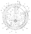
- FIG. 2 illustrates a steering device from FIG. 1 , partially in a top-down view (monocoque shell 36 ), partially in an outline (the rest).
- FIG. 3 a is a perspective exploded view of the steering device of FIG. 1 from the side, from slightly below.
- FIG. 3 b illustrates a shell-shaped heating element with carrier and heating conductor, integrated into the steering device of FIG. 3 .
- FIG. 3 c illustrates an upper mantle shell of the steering device of FIG. 3 a ) as a module of two rigid half-shells with a heating element placed between, as per FIG. 3 b ).
- FIG. 4 a is a perspective detail view of a lower mantle shell and an attachment point of a feed device.
- FIG. 4 b is a simplified depiction of a feed device and a return device for a steering device from FIG. 3 ; to enhance visibility, the individual connection lines of the steering device of FIG. 2 are not shown.
- FIG. 5A a is a cross section through the handle of the steering device in the area A-A with flow passing through the cross section in a single direction.
- FIG. 5A b illustrates a longitudinal section through the handle of the steering device in the area A-A
- FIG. 5B a is a cross section through the handle of the steering device in the area B-B with screw-shaped flow passing through the cross section in two opposite directions.
- FIG. 5B b is a cross section through the handle of the steering device in the area B-B with reversal of flow by one solid handle section 36 .
- FIG. 5C a is a cross section through the handle of the steering device in the area C-C with a hollow-cylinder-shaped flow passing through the cross section in two opposing directions.
- FIG. 5C b is a longitudinal section through the handle of the steering device in the area C-C with C-C with two opposing air flows at two differing height levels relative to the handle axis, which are reversed by a solid handle section 36 .
- a vehicle means a device for transport of persons and/or freight, such as vehicles on land, water, railways and in the air, especially aircraft, ships and automotive vehicles.
- the invention additionally relates to a steering mechanism 2 , such as steering wheels of motor vehicles as per FIG. 2 , control sticks or aircraft or drag links of motorcycles.
- a steering mechanism 2 such as steering wheels of motor vehicles as per FIG. 2 , control sticks or aircraft or drag links of motorcycles.
- the at least one control mechanism has a pivot pole 3 .
- Pivot pole means the reference point or the reference axis about which a steering mechanism is moved to generate a steering signal. Examples are a so-called front end tor a motorcycle steering bar or the steering wheel cup with a steering wheel, a centering point with a multidimensional-operation control stick or some other reference point with a nonrotary-operating steering system such as sliding rheostats.
- the at least one steering mechanism has at least one spoke 4 .
- Spoke means a device for connecting the handle 5 with the pivot pole 3 for transferring mechanical forces and especially guiding motions. Examples are spokes of a steering wheel, steering bars of a motorcycle guide mechanism or the center piece of a control stick. They are provided in a sufficient number for stable suspension of the handle or handles, for example one spoke for a control stick, two for steering rods and two or more for steering wheels.
- the at least one steering mechanism has at least one handle 5 .
- Handle means a device for grasping and applying adjustment forces, especially for manual adjustment of steering devices, of doors, or for operation of motors. Examples are steering handles on motorcycles or steering wheel rings on steering wheels. Especially suited for this are knobs, rods or annular or arc-shaped round profiles made for example of wood, plastic or metal.
- the at least one handle has at least one handle framework 6 for sufficient stability and stiffness of the steering mechanism.
- Handle framework means a support structure to admit and transmit mechanical loads acting on the steering mechanism, such as a steering wheel core or a control stick shaft.
- tubes or U-profiles are suitable which are have at least partially hollow interiors. Stable materials for this are steel, aluminum or carbon fiber materials.
- the at least one handle has at least one jacket 7 according to FIGS. 3 to 5 .
- a jacket means a device which surrounds the handle framework, or, if such is lacking, assumes its function as an exoskeletal structure. This provides a safe and comfortably grippable surface and a screening of functional elements in the handle from harmful outside influences such as sweat. Conversely, the comfort of the user is not hampered by installed components. For simple installation consisting of few parts, and a protective mantle closed roundabout, at low cost and high utilization comfort, hollow cylinders, hollow rings and linear or curved U profiles are preferred.
- the length of the jacket preferably matches the length of the handle piece, thus for example the entire steering-wheel circumference.
- the outer diameter of such a jacket corresponds to the outer diameter of the handle.
- its inner diameter preferably allows a gap 40 through which air can pass between the handle framework and the jacket. This gap between the handle framework and the jacket preferably is at least 2 mm, and better 5 mm.
- the at least one jacket has at least one carrying shell 8 .
- Carrying shell means a device for supporting and reinforcing a jacket, for example through a U profile curved about two axes. Their number ensures a sufficient form stiffness, or one that is mutually reinforcing.
- a first load-admitting outer shell 8 a with a second shell 8 b of a heat carrier bearing a heat conductor placed in it, and a third self-supporting shell 8 c for an air-directing channel as per FIG. 3 c ).
- a carrier shell is for example positioned on an outer side of a jacket, in its middle or on its inner side. It is favorable for a carrier shell to have an outer upholstery or covering. Injection-moldable polymers, fiber-reinforced composite material or hard or soft foams or the like are suitable for the carrier shell 8 as material, for simple assembly and safe usage.
- the at least one jacket has at least one attendant layer 9 .
- Attendant layer means a layer with an additional function, placed on a carrier shell. Examples are planar textile or foil heating elements or an aluminum layer lying above for improved heat distribution on the handle surface.
- An attendant layer can by itself form a carrier shell 8 b . In favorable fashion, all attendant layers of the jacket are united with the carrier layer or layers into shell-like modules, to facilitate assembly. This permits a combination of functions in the jacket within or outside a carrier shell, without these functions being a mutual hindrance.
- the at least one jacket has at least one partial shell 10 for simplified assembly without parts that have low flexural strength.
- Partial shell means a component or an assembly, which is designated for the formwork of a partial section of a handle.
- it is a self-supporting component, thus not having low flexural strength.
- an upper and a lower, single- or multi-layer half shell made of U profiles is suitable, which is meant to admit the handle framework and in sections to surround it. A number of two or more per handle facilitates the assembly.
- the at least one handle has an upholstery piece 42 made, for example, of foamed polyurethane.
- the at least one handle has at least one covering 43 to provide decorative trim to a handle and to mechanically protect it.
- Covering means a single- or multiple-layer planar structure that is placed at least in sections on the surface of a handle, and/or at least partially covers it.
- Cooling device means an object that is suited to influence an area to be cooled, with regard to at least one climatic parameter, for example for heating, ventilation, moisturizing or removal of moisture, and/or cooling.
- the at least one cooling device 15 has at least one temperature-control device 17 .
- Temperature-control device means a device which serves for deliberate temperature control of a user or of an object to be heated, especially for raising, maintaining or lowering the temperature, such as heating, cooling or ventilating devices.
- the invention relates to a heating device 16 , which preferably comprises the temperature control device or a component part of it.
- a heating device means a device that provides thermal energy for specific heating of its surroundings, and emits conductively, convectively and/or through thermal radiation to its surroundings. Examples are devices with at least one electrical resistance heater, a heat pump, a radiator, or a heating spiral, with multiples of these components, also of differing types, also possibly being present. It is favorable if a planar heating element 16 b is provided in a jacket for heating a handle surface and additionally a Peltier element 16 a or a PTC heating module is provided in an air flow for heating the air.
- the at least one heating device 16 has at least one filament rheostat 18 for direct or indirect heating of a handle.
- Filament rheostat means an ohmic resistance or some other electrical component which converts electrical into thermal energy when current passes through. Examples are a plurality of heating sections made of carbon fibers, PCT heating modules connected in an air flow, layers made of an electrically conducting plastic, metal foils such as those made of aluminum or individual large-area heating sections made of metallic strands as in FIG. 3 b ). For example, positions above, in or below a layer, a jacket, or a carrier shell are favorable for the best possible, direct heat transfer to the surface to be temperature-controlled.
- a filament rheostat is at least partially embedded in a carrier shell, especially during preferably plastic displacement of carrier material, so as to not to calk outwards.
- temperature control device 17 and the filament rheostat 18 illustrated in Fig. 2 of the drawings are illustrated in the form of schematic graphical representations or drawing symbols (e.g., rectangular boxes).
- location, size, and/or shape of the graphical representation of the temperature control device 17 and the filament rheostat 18 illustrated in FIG. 2 may not be representative of the actual location, size, and shape of these features.
- the at least one temperature-control device exhibits at least one cooling device 19 for removal of excess thermal energy, especially through insolation.
- Cooling device means a device to lower the temperature of a surface to be cooled or an object to be cooled, such as Peltier elements, thermal conduction pipes or ventilation devices such as fans.
- a position at a distance from temperature-controlled zones promotes simple assembly and reduced structural space, for example in the direction of flow immediately behind a fan, especially close to, or in, a pivot pole of the steering mechanism.
- Fans with integrated Peltier modules are favorable for a modular combination of the fan and cooling device.
- the at least one cooling device exhibits at least one ventilation device 20 .
- Ventilation device means a device that can be used for deliberate alteration of the air composition or the air flows in a specific two-dimensional or three-dimensional area.
- the at least one ventilation device exhibits at least one air supply device 21 .
- Air supply device means a device for moving of air. Examples are fans, especially a radial fan as in FIG. 3 a ) and FIG. 4 b ) or an onboard air conditioner.
- the at least one ventilation or air conditioning device exhibits at least one air guidance device 22 .
- Air guidance device means a device which can guide air in at least one direction between a zone to be air-conditioned and an air feed device or along a zone to be ventilated.
- the least one air guidance device and especially a handle distributor possess at least one spacer device 23 .
- Spacer device means a device which keeps open an air guidance device or components thereof at least partially for an air flow even when mechanical loads are acting from without. Knob- or fin-shaped profiles of a deflecting vane or of a jacket are suitable.
- the at least one air guidance device exhibits at least one feed device 24 .
- Feed device means a device for feeding in or fresh or temperature-controlled air from an air feeding device in a handle distributor, for example through rectangular or round hollow profiles or along open U profiles whose open side is closed by a spoke, for example.
- the number of them is chosen so that it is possible to supply the handle uniformly at every position.
- at least one of these, preferably two and more are preferably situated in specular or rotational symmetry relative to each other to the steering mechanism.
- the width of them permits optical coverage and for example corresponds roughly to the width of the spokes.
- the structural height of them maintains the gripping capacity, in that for example the cables are flattened in the sections 51 close to the handle.
- the feed device 24 is for example rectangular or oval. It is preferred that their surface corresponds to the cross sectional surface of a handle distributor 26 impinging on it Its position allows for the steering wheel to be operable without disturbance, tor example below and at least in essence along a spoke or below the steering-wheel plane.
- a shatter-resistant and robust component such as injection-moldable plastic, metal or wood is preferred as the material.
- the at least one air guidance device exhibits at least one return-flow device 25 .
- Return-flow device means a device to return air from a handle distributor into an air feed device, especially for diverting air having an undesired temperature out of the handle.
- the feed device Rational coordination of the feed and return-flow device results in an arrangement in which the two a) exhibit attachments situated to be offset by 90 degrees, for example, to each other along the handle; b) form a forward- and rearward-line combined next to each other in a channel shaft; or c) one of the two devices is dispensed with, if air is to be transported without an internal reversal of direction only through air openings in a jacket.
- the at least one ventilation device exhibits at least one handle distributor 26 for ventilation or back-ventilation of a handle.
- Handle distributor means a device for collecting, distributing and/or directing air within or along the handle, for example, through pipes or gaps which connect one or more attachment or ventilation openings with one another.
- the at least one handle distributor exhibits at least one inlet line 26 for a distribution of air within or along the handle.
- Inlet line means a device through which air enters from the surroundings or the air feed device into the handle. Its shape produces a uniform distribution of air and heat in the handle, especially about the entire cross-sectional circumference of the handle, for example by means of screw or U-profile shaped or hollow-cylinder cavities. Their width permits a low-friction air flow within the air guidance device. Examples of this are dimensions which correspond to the feed device.
- the inlet line is directed, for example, parallel along the handle or the corresponding handle section, wound in helical fashion about a longitudinal axis of the handle as in FIG. 5B or surrounding it concentrically as in FIG. 5C .
- At least in part are identical with those of the handle distributor, a spoke or a separator device between the inlet line and an outlet line.
- at least one inlet line is positioned at least in part within a handle, especially within a jacket and outside of a handle framework.
- the at least one handle distributor exhibits at least one outlet line 28 for directing air out of the handle.
- Outlet line means a device through which air exits from the handle into the surroundings or to the air feed device.
- the shape, width, alignment, material and placement correspond to those of the inlet line. Placement at the same height relative to the inlet line effects a contradirectional guidance of two flows on the same plane.
- a staggered guidance of exhaust air at a level lower than the inlet air provides for homogeneous and efficient temperature control. Examples are contradirectional and helical inlet and outlet flows on the same cylindrical jacket ( FIG. 5B ) or a guidance of exhaust air in the outlet line in a layer lying below the inlet line ( FIG. 5C ).
- the at least one handle distributor exhibits a separator device 29 , 29 ′.
- Separator device means a device for spatial separation of the content of the inlet line and the outlet line. The number of the separator devices is chosen so that they cause more than one air flow through the handle to be generated. This allows faster temperature adjustment via simultaneous temperature regulation of multiple feed points, homogeneous air distribution and/or closed circulatory loops. It is favorable if at least one is provided with back-and-forth guidance of the planes differing from each other at the same height level relative to the longitudinal axis of the handle framework, or at least two helical-shaped separating devices. They are, for example, aligned equidistant in interval to and along a central handle axis or a spoke.
- the separating device is part of an entry or exit guidance wall, a jacket layer and/or a handle recess.
- the air conditioning device works in a suction, blowing or a combined operational mode.
- the air transfer device 21 of the ventilation device 20 moves air to the handle 5 of the steering mechanism 2 . While doing so it flows through a Peltier element 16 a , where it is heated or cooled as desired. Then the air flows via multiple feed devices 24 into the handle distributor 26 of handle 5 .
- the blowing mode can be activated via a feed device 24 and additionally a flow of excess air in the suction mode can be brought back by suction via a separate return device 25 to the air transfer device 21 .
- air provided by the air transfer device can first heat jacket 7 in a tubular flow in the inlet line 27 , and then be brought back in a concentric, interior tubular outlet line 28 , at an interval from jacket 7 as waste air or to the air transfer device 21 .
- an air flow can be brought in helically through an inlet line 27 along a section of a handle 5 and helically around the handle 5 . If this handle Is attachable only at one end, then via a second helical line, the outlet line 28 , the air flow can be again directed back.
- These lines are produced within the handle distributor 26 in that two rubber strands are placed in helical fashion and displaced relative to each other along the handle 5 beneath the jacket 7 .
- a fourth combined mode 5 at location 84 , two air flows can also be guided in helical fashion and running counter to each other through the handle 5 , if the corresponding section is attached at both ends to a feed device and simultaneously to a return device. This makes possible rapid and homogenous air conditioning.
- a surface heating element 16 b can be operated.
Landscapes
- Engineering & Computer Science (AREA)
- Mechanical Engineering (AREA)
- Transportation (AREA)
- Chemical & Material Sciences (AREA)
- Combustion & Propulsion (AREA)
- Physics & Mathematics (AREA)
- Power Engineering (AREA)
- Thermal Sciences (AREA)
- Steering Controls (AREA)
- Air-Conditioning For Vehicles (AREA)
- Automation & Control Theory (AREA)
- Mathematical Physics (AREA)
Applications Claiming Priority (6)
| Application Number | Priority Date | Filing Date | Title |
|---|---|---|---|
| DE102012019065 | 2012-09-28 | ||
| DE102012019065 | 2012-09-28 | ||
| DE102012019065.4 | 2012-09-28 | ||
| DE102012019765.9 | 2012-10-09 | ||
| DE102012019765.9A DE102012019765A1 (de) | 2012-09-28 | 2012-10-09 | Temperier-/Klimatisierungseinrichtung für Griffe, insbesondere von Lenkeinrichtungen |
| DE102012019765 | 2012-10-09 |
Publications (2)
| Publication Number | Publication Date |
|---|---|
| US20140090513A1 US20140090513A1 (en) | 2014-04-03 |
| US9399480B2 true US9399480B2 (en) | 2016-07-26 |
Family
ID=50276128
Family Applications (1)
| Application Number | Title | Priority Date | Filing Date |
|---|---|---|---|
| US14/028,720 Expired - Fee Related US9399480B2 (en) | 2012-09-28 | 2013-09-17 | Heating and cooling device for handles, especially of steering mechanisms |
Country Status (5)
| Country | Link |
|---|---|
| US (1) | US9399480B2 (de) |
| JP (1) | JP5864502B2 (de) |
| KR (1) | KR101613875B1 (de) |
| CN (1) | CN103738390B (de) |
| DE (2) | DE102012019765A1 (de) |
Cited By (5)
| Publication number | Priority date | Publication date | Assignee | Title |
|---|---|---|---|---|
| US20190202262A1 (en) * | 2018-01-02 | 2019-07-04 | Ford Global Technologies, Llc | Steering wheel and motor vehicle |
| US11584424B2 (en) * | 2018-08-03 | 2023-02-21 | Audio Mobil Elektronik Gmbh | Operator control unit for a steering wheel, and steering wheel having the same |
| WO2023168060A1 (en) | 2022-03-04 | 2023-09-07 | Gentherm Incorporated | Method for estimating surface temperature |
| WO2023215350A1 (en) | 2022-05-03 | 2023-11-09 | Gentherm Incorporated | Method for controlling a conductive or convective effector |
| WO2023244435A1 (en) | 2022-06-16 | 2023-12-21 | Gentherm Incorporated | Conditioning system for thermal effectors |
Families Citing this family (38)
| Publication number | Priority date | Publication date | Assignee | Title |
|---|---|---|---|---|
| US7587901B2 (en) | 2004-12-20 | 2009-09-15 | Amerigon Incorporated | Control system for thermal module in vehicle |
| US8539624B2 (en) | 2006-05-31 | 2013-09-24 | Gentherm Incorporated | Structure based fluid distribution system |
| US20080087316A1 (en) | 2006-10-12 | 2008-04-17 | Masa Inaba | Thermoelectric device with internal sensor |
| US8065763B2 (en) | 2006-10-13 | 2011-11-29 | Amerigon Incorporated | Air conditioned bed |
| WO2009036077A1 (en) | 2007-09-10 | 2009-03-19 | Amerigon, Inc. | Operational control schemes for ventilated seat or bed assemblies |
| US9125497B2 (en) | 2007-10-15 | 2015-09-08 | Gentherm Incorporated | Climate controlled bed assembly with intermediate layer |
| JP2011514180A (ja) | 2008-02-01 | 2011-05-06 | アメリゴン インコーポレイティド | 熱電デバイスのための凝縮体センサ及び湿度センサ |
| CN102098947B (zh) | 2008-07-18 | 2014-12-10 | 阿美里根公司 | 气候受控床组件 |
| US8332975B2 (en) | 2009-08-31 | 2012-12-18 | Gentherm Incorporated | Climate-controlled topper member for medical beds |
| US9121414B2 (en) | 2010-11-05 | 2015-09-01 | Gentherm Incorporated | Low-profile blowers and methods |
| WO2013052823A1 (en) | 2011-10-07 | 2013-04-11 | Gentherm Incorporated | Thermoelectric device controls and methods |
| US9989267B2 (en) | 2012-02-10 | 2018-06-05 | Gentherm Incorporated | Moisture abatement in heating operation of climate controlled systems |
| KR20150037904A (ko) | 2012-07-06 | 2015-04-08 | 젠썸 인코포레이티드 | 유도 충전 어셈블리를 냉각하기 위한 시스템 및 방법 |
| US9662962B2 (en) | 2013-11-05 | 2017-05-30 | Gentherm Incorporated | Vehicle headliner assembly for zonal comfort |
| JP6524088B2 (ja) | 2013-12-05 | 2019-06-05 | ジェンサーム インコーポレイテッドGentherm Incorporated | 環境制御シート用のシステムおよび方法 |
| KR102051617B1 (ko) | 2014-02-14 | 2019-12-03 | 젠썸 인코포레이티드 | 전도식 대류식 기온 제어 시트 |
| KR102637609B1 (ko) | 2014-05-09 | 2024-02-15 | 젠썸 인코포레이티드 | 기후 제어 시트 조립체 |
| US9815488B2 (en) * | 2014-05-13 | 2017-11-14 | Gentherm Gmbh | Temperature control device for a steering device |
| US9033366B1 (en) * | 2014-07-02 | 2015-05-19 | Nissan North America, Inc. | System for cooling a steering wheel and a method of making |
| JP6914832B2 (ja) | 2014-10-31 | 2021-08-04 | ジェンサーム インコーポレイテッドGentherm Incorporated | 車両ミクロ気候システムと制御方法 |
| EP3726594B1 (de) | 2014-11-14 | 2022-05-04 | Gentherm Incorporated | Heiz- und kühltechnologien |
| US11639816B2 (en) | 2014-11-14 | 2023-05-02 | Gentherm Incorporated | Heating and cooling technologies including temperature regulating pad wrap and technologies with liquid system |
| US11857004B2 (en) | 2014-11-14 | 2024-01-02 | Gentherm Incorporated | Heating and cooling technologies |
| KR20160133315A (ko) | 2015-05-12 | 2016-11-22 | 주식회사 대창 | 차량용 핸들 |
| DE102015219486B3 (de) * | 2015-10-08 | 2016-10-13 | Volkswagen Aktiengesellschaft | Lenkrad für ein Fahrzeug |
| WO2017173222A1 (en) | 2016-04-01 | 2017-10-05 | Gentherm Inc. | Occupant thermal state detection and comfort adjustment system and method |
| US20190263440A1 (en) * | 2016-09-16 | 2019-08-29 | Key Safety Systems, Inc. | Climate controlled steering wheel |
| US10991869B2 (en) | 2018-07-30 | 2021-04-27 | Gentherm Incorporated | Thermoelectric device having a plurality of sealing materials |
| DE112019005983T5 (de) | 2018-11-30 | 2021-09-09 | Gentherm Incorporated | Thermoelektrisches konditionierungssystem und verfahren |
| US11152557B2 (en) | 2019-02-20 | 2021-10-19 | Gentherm Incorporated | Thermoelectric module with integrated printed circuit board |
| WO2021102450A1 (en) | 2019-11-20 | 2021-05-27 | Gentherm Inc. | Automotive seat based microclimate system |
| CN114867621A (zh) | 2019-11-20 | 2022-08-05 | 金瑟姆股份有限公司 | 基于汽车座椅的微气候系统 |
| US20230050032A1 (en) | 2020-02-05 | 2023-02-16 | Gentherm Incorporated | Thermal conditioning system including segmented architecture |
| WO2021158856A1 (en) | 2020-02-05 | 2021-08-12 | Gentherm Incorporated | Thermophysiologically-based microclimate control system |
| WO2021158867A1 (en) | 2020-02-05 | 2021-08-12 | Gentherm Incorporated | Vehicle microclimate personalization based on occupant thermophysiology |
| DE112022000562T5 (de) | 2021-03-16 | 2023-11-23 | Gentherm Inc. | Mikroklimasystem für einen Fahrzeuginsassen und entsprechendes Verfahren |
| US20240131902A1 (en) | 2021-03-16 | 2024-04-25 | Gentherm Incorporated | Automotive seat based microclimate system |
| US20240140284A1 (en) | 2021-05-28 | 2024-05-02 | Gentherm Incorporated | Method to control thermal sensation according to occupancy of seats |
Citations (67)
| Publication number | Priority date | Publication date | Assignee | Title |
|---|---|---|---|---|
| US1587586A (en) * | 1925-10-21 | 1926-06-08 | Hollis Homer | Heated steering wheel |
| US1615635A (en) | 1926-05-17 | 1927-01-25 | Kuno Shichigoro | Heating steering wheel |
| US1617226A (en) * | 1924-03-15 | 1927-02-08 | Alexander D White | Steering-wheel warmer |
| US2163450A (en) | 1938-02-12 | 1939-06-20 | Louise B Preble | Heated steering wheel |
| US2251370A (en) * | 1941-05-02 | 1941-08-05 | George E Motzer | Heater for motor vehicles |
| GB779918A (en) * | 1956-08-31 | 1957-07-24 | Lawrence Frank Fulham | Improvements in electrical heaters for steering wheels |
| US2835777A (en) | 1956-06-28 | 1958-05-20 | Gen Motors Corp | Heated steering wheel |
| US3165620A (en) | 1962-02-23 | 1965-01-12 | Richard D Miller | Heated steering wheel for vehicles |
| US3298750A (en) | 1965-08-02 | 1967-01-17 | Federal Screw Works | Fastener assembly |
| US3489031A (en) * | 1966-11-24 | 1970-01-13 | Kamei Auto Komfort Wolfsburg K | Cover for automobile steering wheels,tennis rackets and the like |
| DE7149043U (de) | 1971-12-28 | 1972-04-20 | Mayer H | Einrichtung zum erwaermen oder kuehlen der lenkraeder von fahrzeugen |
| US3876844A (en) | 1972-02-16 | 1975-04-08 | Daimler Benz Ag | Steering wheel for motor vehicles |
| US4547655A (en) | 1982-11-02 | 1985-10-15 | Nissan Motor Co., Ltd. | Electrically heated steering wheel |
| US4549069A (en) | 1984-05-14 | 1985-10-22 | Eray Oge | Electrically heated steering wheel cover |
| US4640340A (en) | 1983-10-21 | 1987-02-03 | Toyoda Gosei Co., Ltd. | Heated or cooled steering wheel |
| JPS62128878A (ja) | 1985-11-30 | 1987-06-11 | Toyoda Gosei Co Ltd | ステアリングホイ−ル |
| DE3713450A1 (de) * | 1987-04-22 | 1988-11-03 | Weber Manfred Peter | Temperieren von lenk- und schalteinrichtungen |
| JPH01178078A (ja) | 1987-12-29 | 1989-07-14 | Tokyo Seat Kk | 車両用ステアリング |
| US4993281A (en) | 1989-05-05 | 1991-02-19 | Miller Jess J | Flexible steering wheel heat shield |
| DE9111356U1 (de) | 1991-09-12 | 1992-01-09 | Reuther, Jens, 8000 Muenchen, De | |
| US5138851A (en) * | 1990-12-14 | 1992-08-18 | Golden Empire Trading Co., Inc. | Active seat cooling system |
| DE29515265U1 (de) | 1995-09-23 | 1996-01-11 | Knapp Hartmut | Lenkradverkleidungen für Kraftfahrzeuge |
| US5605643A (en) | 1995-12-21 | 1997-02-25 | Reece; Mildred D. | Heated steering wheel with a plurality of radially extending wires for affording suitable heat conductivity |
| JPH10230857A (ja) | 1997-02-21 | 1998-09-02 | Nippon Oil Co Ltd | 温度調節機能付ステアリングホイール |
| US5847360A (en) | 1995-12-05 | 1998-12-08 | Warme-und Elektrotechnik B. Ruthenberg GmbH | Electric steering-wheel heating element |
| US5850741A (en) | 1997-06-09 | 1998-12-22 | Feher; Steve | Automotive vehicle steering wheel heating and cooling apparatus |
| US5948347A (en) | 1998-06-01 | 1999-09-07 | General Motors Corporation | Method of making a steering hand wheel insert |
| US6007420A (en) | 1997-08-18 | 1999-12-28 | Daimlerchrysler Ag | Operating element in a motor vehicle |
| EP0992416A2 (de) | 1998-10-06 | 2000-04-12 | TRW Automotive Safety Systems GmbH & Co. KG | Belüftetes Lenkrad |
| US6093908A (en) | 1999-04-30 | 2000-07-25 | Delphi Technologies Inc. | Heated steering wheel |
| US6172342B1 (en) | 1999-09-15 | 2001-01-09 | Delphi Technologies, Inc. | Steering wheel heating system |
| DE19951224A1 (de) | 1999-10-20 | 2001-05-10 | Petri Ag | Vorrichtung zur Temperierung eines Bauteils |
| DE19953467A1 (de) | 1999-11-05 | 2001-05-17 | Webasto Systemkomponenten Gmbh | Belüftungsvorrichtung für ein Lenkrad eines Fahrzeugs |
| US6326593B1 (en) | 1998-02-04 | 2001-12-04 | Takata-Petri Ag | Heating element for a part of an automobile which is held, especially the steering wheel |
| US6392195B1 (en) | 2000-11-27 | 2002-05-21 | Breed Automotive Technology, Inc. | Heated steering wheel |
| US6414270B1 (en) | 2000-09-21 | 2002-07-02 | Nihon Plast Co., Ltd. | Heater, heater-equipped steering wheel, and method of manufacturing such steering wheel |
| US6441344B1 (en) | 1999-03-01 | 2002-08-27 | Takata-Petri Ag | Heatable steering wheel, and rim and method thereof |
| US20020166407A1 (en) | 1999-10-20 | 2002-11-14 | Takata-Petri Ag | Steering wheel with heat accumulating mechanism |
| US6509552B1 (en) | 2002-03-05 | 2003-01-21 | Edward K. Roske | Temperature-controlled steering wheel |
| US6512202B2 (en) | 2000-02-28 | 2003-01-28 | Delphi Technologies, Inc. | Apparatus and method for heating a steering wheel |
| US6533184B1 (en) | 1999-10-18 | 2003-03-18 | Kiwan Kim | Comfort steering wheel |
| WO2003047942A1 (en) | 2001-12-05 | 2003-06-12 | Autoliv Development Ab | A steering wheel provided with a device for heating or cooling the rim of said steering wheel |
| US6668683B2 (en) | 2000-04-11 | 2003-12-30 | Trw Automotive Safety Systems Gmbh & Co. Kg | Vehicle steering wheel |
| US6668682B1 (en) | 1998-07-23 | 2003-12-30 | Takata-Petri Ag | Steering wheel comprising a decorative covering |
| US6727467B1 (en) | 2003-01-31 | 2004-04-27 | W.E.T. Automotive Systems Ag | Heated handle and method of forming same |
| US6762394B2 (en) | 2000-07-22 | 2004-07-13 | Breed Automotive Technology, Inc. | Heated steering wheel |
| US20040168540A1 (en) | 2003-01-08 | 2004-09-02 | Michael Weiss | Steering device with cooling device |
| DE202004005181U1 (de) | 2004-03-30 | 2004-09-09 | W.E.T. Automotive Systems Ag | Temperiervorrichtung für Teile einer Fahrzeuginnenausstattung |
| US6838647B2 (en) | 2001-05-29 | 2005-01-04 | W.E.T. Automotive Systems Ag | Flexible heating element |
| US6862807B2 (en) | 2000-12-08 | 2005-03-08 | Trw Automotive Safety Systems Gmbh & Co. Kg | Method of producing a steering wheel skeleton and vehicle steering wheel |
| DE102004006639A1 (de) | 2004-02-10 | 2005-09-01 | Dan Donisa | Verfahren und Vorrichtung zur Verbesserung der Gebrauchseigenschaften eines Lenkrads |
| DE102004027008A1 (de) | 2004-05-28 | 2005-12-29 | Takata-Petri Ag | Beheizbares Furnierelement für Kfz-Lenkräder und Verfahren zur Herstellung eines solchen Furnierelementes |
| US20060033628A1 (en) | 2004-08-12 | 2006-02-16 | Landon Duval | Steering wheel vapor collection and sensing system using a chemical element |
| US7019261B2 (en) | 2003-02-06 | 2006-03-28 | Delphi Technologies, Inc. | Apparatus and method for a steering wheel with a preformed heating element |
| US20060121843A1 (en) | 2004-12-07 | 2006-06-08 | Nissan Technical Center North America, Inc. | Steering wheel ventilation system and method |
| JP2006176037A (ja) | 2004-12-24 | 2006-07-06 | Aisin Seiki Co Ltd | ハンドル冷却加熱装置 |
| US20070101728A1 (en) | 2005-11-03 | 2007-05-10 | Valeo Schalter Und Sensoren Gmbh | Device for a steering system, particularly for a motor vehicle |
| USD559158S1 (en) | 2006-11-11 | 2008-01-08 | Garcia Jose J | Heated and cooled steering wheel |
| US7378615B1 (en) | 2006-06-12 | 2008-05-27 | King Jason A | Steering wheel heating apparatus |
| DE60317179T2 (de) | 2003-06-24 | 2008-08-14 | Key Safety Systems, Inc., Sterling Heights | Beheiztes und gekühltes Lenkrad |
| US20080210048A1 (en) | 2002-04-25 | 2008-09-04 | Mitsuru Yoneyama | Heating element for steering wheel |
| US20090114368A1 (en) | 2007-11-02 | 2009-05-07 | Minoru Niwa | Heated or cooled steering wheel |
| EP2065234A1 (de) | 2007-11-28 | 2009-06-03 | Peugeot Citroen Automobiles SA | Luftverteiler für Innenraum eines Kraftfahrzeugs |
| US20100288073A1 (en) | 2009-05-14 | 2010-11-18 | Shin Gi Ug | Steering wheel for automobile and method of fabricating the same |
| US8015835B2 (en) | 2007-11-02 | 2011-09-13 | Korea Delphi Automotive Systems Corporation | Internal cooling apparatus for automobiles |
| US20130180354A1 (en) | 2012-01-12 | 2013-07-18 | Ford Global Technologies, Llc | Heated/cooled thermoelectric steering wheel |
| DE202012009655U1 (de) | 2012-10-09 | 2014-01-10 | W.E.T. Automotive Systems Ag | Temperier-/Klimatisierungseinrichtung für Griffe, insbesondere von Lenkeinrichtungen |
Family Cites Families (11)
| Publication number | Priority date | Publication date | Assignee | Title |
|---|---|---|---|---|
| JPS6280154A (ja) * | 1985-10-02 | 1987-04-13 | Toyoda Gosei Co Ltd | ステアリングホイ−ル |
| JPH0558305A (ja) * | 1991-08-30 | 1993-03-09 | Kyocera Corp | ステアリング装置 |
| JPH11235981A (ja) * | 1998-02-19 | 1999-08-31 | Masaru Nara | 自動車用ステアリングホイールの温湿度調整装置 |
| DE29902044U1 (de) * | 1999-02-05 | 1999-04-08 | Trw Automotive Safety Sys Gmbh | Heizbares Holzlenkrad |
| JP4150477B2 (ja) * | 1999-10-06 | 2008-09-17 | 日本プラスト株式会社 | ステアリングホイール |
| JP2004142615A (ja) * | 2002-10-24 | 2004-05-20 | Denso Corp | 空調式ハンドル |
| DE10321220B3 (de) * | 2003-05-12 | 2004-12-30 | Formtec Technische Formholzteile Gmbh | Verfahren zum Herstellen von Segment- oder Endlosbögen für Lenkräder sowie Lenkrad |
| DE10346942B3 (de) * | 2003-10-09 | 2005-06-30 | Formtec Technische Formholzteile Gmbh | Beheizbare Lenkvorrichtung, Halbfertigteil hierfür und Verfahren zur Herstellung eines Halbfertigteils |
| JP4857695B2 (ja) * | 2005-10-05 | 2012-01-18 | トヨタ自動車株式会社 | 把持部材温度制御装置及びステアリング装置 |
| KR200423230Y1 (ko) * | 2006-05-25 | 2006-08-03 | 문동율 | 핸들 온도조절장치 |
| CN201201639Y (zh) * | 2008-04-16 | 2009-03-04 | 童荷 | 冷暖方向盘 |
-
2012
- 2012-10-09 DE DE102012019765.9A patent/DE102012019765A1/de not_active Withdrawn
- 2012-10-09 DE DE102012023996.3A patent/DE102012023996A1/de not_active Ceased
-
2013
- 2013-09-17 KR KR1020130112052A patent/KR101613875B1/ko active IP Right Grant
- 2013-09-17 US US14/028,720 patent/US9399480B2/en not_active Expired - Fee Related
- 2013-09-27 CN CN201310451632.5A patent/CN103738390B/zh not_active Expired - Fee Related
- 2013-09-27 JP JP2013201722A patent/JP5864502B2/ja not_active Expired - Fee Related
Patent Citations (71)
| Publication number | Priority date | Publication date | Assignee | Title |
|---|---|---|---|---|
| US1617226A (en) * | 1924-03-15 | 1927-02-08 | Alexander D White | Steering-wheel warmer |
| US1587586A (en) * | 1925-10-21 | 1926-06-08 | Hollis Homer | Heated steering wheel |
| US1615635A (en) | 1926-05-17 | 1927-01-25 | Kuno Shichigoro | Heating steering wheel |
| US2163450A (en) | 1938-02-12 | 1939-06-20 | Louise B Preble | Heated steering wheel |
| US2251370A (en) * | 1941-05-02 | 1941-08-05 | George E Motzer | Heater for motor vehicles |
| US2835777A (en) | 1956-06-28 | 1958-05-20 | Gen Motors Corp | Heated steering wheel |
| GB779918A (en) * | 1956-08-31 | 1957-07-24 | Lawrence Frank Fulham | Improvements in electrical heaters for steering wheels |
| US3165620A (en) | 1962-02-23 | 1965-01-12 | Richard D Miller | Heated steering wheel for vehicles |
| US3298750A (en) | 1965-08-02 | 1967-01-17 | Federal Screw Works | Fastener assembly |
| US3489031A (en) * | 1966-11-24 | 1970-01-13 | Kamei Auto Komfort Wolfsburg K | Cover for automobile steering wheels,tennis rackets and the like |
| DE7149043U (de) | 1971-12-28 | 1972-04-20 | Mayer H | Einrichtung zum erwaermen oder kuehlen der lenkraeder von fahrzeugen |
| US3876844A (en) | 1972-02-16 | 1975-04-08 | Daimler Benz Ag | Steering wheel for motor vehicles |
| US4547655A (en) | 1982-11-02 | 1985-10-15 | Nissan Motor Co., Ltd. | Electrically heated steering wheel |
| US4640340A (en) | 1983-10-21 | 1987-02-03 | Toyoda Gosei Co., Ltd. | Heated or cooled steering wheel |
| US4549069A (en) | 1984-05-14 | 1985-10-22 | Eray Oge | Electrically heated steering wheel cover |
| JPS62128878A (ja) | 1985-11-30 | 1987-06-11 | Toyoda Gosei Co Ltd | ステアリングホイ−ル |
| DE3713450A1 (de) * | 1987-04-22 | 1988-11-03 | Weber Manfred Peter | Temperieren von lenk- und schalteinrichtungen |
| JPH01178078A (ja) | 1987-12-29 | 1989-07-14 | Tokyo Seat Kk | 車両用ステアリング |
| US4993281A (en) | 1989-05-05 | 1991-02-19 | Miller Jess J | Flexible steering wheel heat shield |
| US5138851A (en) * | 1990-12-14 | 1992-08-18 | Golden Empire Trading Co., Inc. | Active seat cooling system |
| DE9111356U1 (de) | 1991-09-12 | 1992-01-09 | Reuther, Jens, 8000 Muenchen, De | |
| DE29515265U1 (de) | 1995-09-23 | 1996-01-11 | Knapp Hartmut | Lenkradverkleidungen für Kraftfahrzeuge |
| US5847360A (en) | 1995-12-05 | 1998-12-08 | Warme-und Elektrotechnik B. Ruthenberg GmbH | Electric steering-wheel heating element |
| US5605643A (en) | 1995-12-21 | 1997-02-25 | Reece; Mildred D. | Heated steering wheel with a plurality of radially extending wires for affording suitable heat conductivity |
| JPH10230857A (ja) | 1997-02-21 | 1998-09-02 | Nippon Oil Co Ltd | 温度調節機能付ステアリングホイール |
| US5850741A (en) | 1997-06-09 | 1998-12-22 | Feher; Steve | Automotive vehicle steering wheel heating and cooling apparatus |
| US6007420A (en) | 1997-08-18 | 1999-12-28 | Daimlerchrysler Ag | Operating element in a motor vehicle |
| US6326593B1 (en) | 1998-02-04 | 2001-12-04 | Takata-Petri Ag | Heating element for a part of an automobile which is held, especially the steering wheel |
| US5948347A (en) | 1998-06-01 | 1999-09-07 | General Motors Corporation | Method of making a steering hand wheel insert |
| US6668682B1 (en) | 1998-07-23 | 2003-12-30 | Takata-Petri Ag | Steering wheel comprising a decorative covering |
| EP0992416A2 (de) | 1998-10-06 | 2000-04-12 | TRW Automotive Safety Systems GmbH & Co. KG | Belüftetes Lenkrad |
| US6481312B1 (en) | 1998-10-06 | 2002-11-19 | Trw Automotive Safety Systems Gmbh & Co. Kg | Ventilated steering wheel |
| US6441344B1 (en) | 1999-03-01 | 2002-08-27 | Takata-Petri Ag | Heatable steering wheel, and rim and method thereof |
| US6093908A (en) | 1999-04-30 | 2000-07-25 | Delphi Technologies Inc. | Heated steering wheel |
| US6172342B1 (en) | 1999-09-15 | 2001-01-09 | Delphi Technologies, Inc. | Steering wheel heating system |
| US6533184B1 (en) | 1999-10-18 | 2003-03-18 | Kiwan Kim | Comfort steering wheel |
| US20020166407A1 (en) | 1999-10-20 | 2002-11-14 | Takata-Petri Ag | Steering wheel with heat accumulating mechanism |
| DE19951224A1 (de) | 1999-10-20 | 2001-05-10 | Petri Ag | Vorrichtung zur Temperierung eines Bauteils |
| DE19953467A1 (de) | 1999-11-05 | 2001-05-17 | Webasto Systemkomponenten Gmbh | Belüftungsvorrichtung für ein Lenkrad eines Fahrzeugs |
| US6512202B2 (en) | 2000-02-28 | 2003-01-28 | Delphi Technologies, Inc. | Apparatus and method for heating a steering wheel |
| US6668683B2 (en) | 2000-04-11 | 2003-12-30 | Trw Automotive Safety Systems Gmbh & Co. Kg | Vehicle steering wheel |
| US6762394B2 (en) | 2000-07-22 | 2004-07-13 | Breed Automotive Technology, Inc. | Heated steering wheel |
| US6414270B1 (en) | 2000-09-21 | 2002-07-02 | Nihon Plast Co., Ltd. | Heater, heater-equipped steering wheel, and method of manufacturing such steering wheel |
| US6392195B1 (en) | 2000-11-27 | 2002-05-21 | Breed Automotive Technology, Inc. | Heated steering wheel |
| US6862807B2 (en) | 2000-12-08 | 2005-03-08 | Trw Automotive Safety Systems Gmbh & Co. Kg | Method of producing a steering wheel skeleton and vehicle steering wheel |
| US6838647B2 (en) | 2001-05-29 | 2005-01-04 | W.E.T. Automotive Systems Ag | Flexible heating element |
| WO2003047942A1 (en) | 2001-12-05 | 2003-06-12 | Autoliv Development Ab | A steering wheel provided with a device for heating or cooling the rim of said steering wheel |
| US6509552B1 (en) | 2002-03-05 | 2003-01-21 | Edward K. Roske | Temperature-controlled steering wheel |
| US20080210048A1 (en) | 2002-04-25 | 2008-09-04 | Mitsuru Yoneyama | Heating element for steering wheel |
| US20040168540A1 (en) | 2003-01-08 | 2004-09-02 | Michael Weiss | Steering device with cooling device |
| US7145102B2 (en) | 2003-01-31 | 2006-12-05 | W.E.T. Automotive Systems Ag | Heated handle and method of forming same |
| US6727467B1 (en) | 2003-01-31 | 2004-04-27 | W.E.T. Automotive Systems Ag | Heated handle and method of forming same |
| US7019261B2 (en) | 2003-02-06 | 2006-03-28 | Delphi Technologies, Inc. | Apparatus and method for a steering wheel with a preformed heating element |
| US7908941B2 (en) | 2003-06-24 | 2011-03-22 | Key Safety Systems, Inc. | Heated and cooled steering wheel |
| DE60317179T2 (de) | 2003-06-24 | 2008-08-14 | Key Safety Systems, Inc., Sterling Heights | Beheiztes und gekühltes Lenkrad |
| DE102004006639A1 (de) | 2004-02-10 | 2005-09-01 | Dan Donisa | Verfahren und Vorrichtung zur Verbesserung der Gebrauchseigenschaften eines Lenkrads |
| DE202004005181U1 (de) | 2004-03-30 | 2004-09-09 | W.E.T. Automotive Systems Ag | Temperiervorrichtung für Teile einer Fahrzeuginnenausstattung |
| DE102004027008A1 (de) | 2004-05-28 | 2005-12-29 | Takata-Petri Ag | Beheizbares Furnierelement für Kfz-Lenkräder und Verfahren zur Herstellung eines solchen Furnierelementes |
| US20060033628A1 (en) | 2004-08-12 | 2006-02-16 | Landon Duval | Steering wheel vapor collection and sensing system using a chemical element |
| US20060121843A1 (en) | 2004-12-07 | 2006-06-08 | Nissan Technical Center North America, Inc. | Steering wheel ventilation system and method |
| JP2006176037A (ja) | 2004-12-24 | 2006-07-06 | Aisin Seiki Co Ltd | ハンドル冷却加熱装置 |
| US20070101728A1 (en) | 2005-11-03 | 2007-05-10 | Valeo Schalter Und Sensoren Gmbh | Device for a steering system, particularly for a motor vehicle |
| DE102005053182A1 (de) | 2005-11-03 | 2007-05-10 | Valeo Schalter Und Sensoren Gmbh | Vorrichtung für ein Lenksystem, insbesondere eines Kraftfahrzeugs |
| US7378615B1 (en) | 2006-06-12 | 2008-05-27 | King Jason A | Steering wheel heating apparatus |
| USD559158S1 (en) | 2006-11-11 | 2008-01-08 | Garcia Jose J | Heated and cooled steering wheel |
| US20090114368A1 (en) | 2007-11-02 | 2009-05-07 | Minoru Niwa | Heated or cooled steering wheel |
| US8015835B2 (en) | 2007-11-02 | 2011-09-13 | Korea Delphi Automotive Systems Corporation | Internal cooling apparatus for automobiles |
| EP2065234A1 (de) | 2007-11-28 | 2009-06-03 | Peugeot Citroen Automobiles SA | Luftverteiler für Innenraum eines Kraftfahrzeugs |
| US20100288073A1 (en) | 2009-05-14 | 2010-11-18 | Shin Gi Ug | Steering wheel for automobile and method of fabricating the same |
| US20130180354A1 (en) | 2012-01-12 | 2013-07-18 | Ford Global Technologies, Llc | Heated/cooled thermoelectric steering wheel |
| DE202012009655U1 (de) | 2012-10-09 | 2014-01-10 | W.E.T. Automotive Systems Ag | Temperier-/Klimatisierungseinrichtung für Griffe, insbesondere von Lenkeinrichtungen |
Non-Patent Citations (1)
| Title |
|---|
| German Office Action, Application No. 10 2012 019 765.9, dated May 23, 2013. |
Cited By (6)
| Publication number | Priority date | Publication date | Assignee | Title |
|---|---|---|---|---|
| US20190202262A1 (en) * | 2018-01-02 | 2019-07-04 | Ford Global Technologies, Llc | Steering wheel and motor vehicle |
| US10814699B2 (en) * | 2018-01-02 | 2020-10-27 | Ford Global Technologies, Llc | Steering wheel and motor vehicle |
| US11584424B2 (en) * | 2018-08-03 | 2023-02-21 | Audio Mobil Elektronik Gmbh | Operator control unit for a steering wheel, and steering wheel having the same |
| WO2023168060A1 (en) | 2022-03-04 | 2023-09-07 | Gentherm Incorporated | Method for estimating surface temperature |
| WO2023215350A1 (en) | 2022-05-03 | 2023-11-09 | Gentherm Incorporated | Method for controlling a conductive or convective effector |
| WO2023244435A1 (en) | 2022-06-16 | 2023-12-21 | Gentherm Incorporated | Conditioning system for thermal effectors |
Also Published As
| Publication number | Publication date |
|---|---|
| KR20140042678A (ko) | 2014-04-07 |
| DE102012023996A1 (de) | 2014-06-12 |
| CN103738390B (zh) | 2016-10-05 |
| JP5864502B2 (ja) | 2016-02-17 |
| DE102012019765A1 (de) | 2014-04-03 |
| US20140090513A1 (en) | 2014-04-03 |
| KR101613875B1 (ko) | 2016-04-20 |
| CN103738390A (zh) | 2014-04-23 |
| JP2014069800A (ja) | 2014-04-21 |
Similar Documents
| Publication | Publication Date | Title |
|---|---|---|
| US9399480B2 (en) | Heating and cooling device for handles, especially of steering mechanisms | |
| US20190329812A1 (en) | Heating and cooling device for handles, especially of steering mechanism | |
| JP5667131B2 (ja) | 加熱装置 | |
| KR101763752B1 (ko) | 특히 운송수단 시트 내 목 부분 온풍 장치로서의 이용을 위한 열풍 송풍기 | |
| US6481312B1 (en) | Ventilated steering wheel | |
| DE202012009655U1 (de) | Temperier-/Klimatisierungseinrichtung für Griffe, insbesondere von Lenkeinrichtungen | |
| US6935944B2 (en) | Air systems for vehicles | |
| CN204236183U (zh) | 气候控制装置和把手、车辆或转向机构 | |
| US10351158B2 (en) | Heating and cooling device for handles | |
| CN104943499A (zh) | 用于把手、特别是转向机构的加热和冷却装置 | |
| CN204236184U (zh) | 气候控制装置和把手、车辆或转向机构 | |
| WO2015149248A1 (en) | Heating and cooling device for handles | |
| US11873106B2 (en) | Cabin air inlet module and cabin air system | |
| CN110154695A (zh) | 通过动力椭圆形叶片实现汽车空气水平引导 | |
| WO2009117988A1 (de) | Klimatisierungseinrichtung für einen sitz | |
| CN104943500A (zh) | 用于把手、特别是转向机构的加热和冷却装置 |
Legal Events
| Date | Code | Title | Description |
|---|---|---|---|
| AS | Assignment |
Owner name: W.E.T. AUTOMOTIVE SYSTEMS AG, GERMANY Free format text: ASSIGNMENT OF ASSIGNORS INTEREST;ASSIGNORS:ZHANG, JONATHAN (YU);ZHANG, FRED (FUFEI);HU, MELINDA (MEIJING);REEL/FRAME:031221/0352 Effective date: 20130913 |
|
| AS | Assignment |
Owner name: GENTHERM GMBH, GERMANY Free format text: CHANGE OF NAME;ASSIGNOR:W.E.T. AUTOMOTIVE SYSTEMS AG;REEL/FRAME:035496/0605 Effective date: 20140428 |
|
| STCF | Information on status: patent grant |
Free format text: PATENTED CASE |
|
| CC | Certificate of correction | ||
| FEPP | Fee payment procedure |
Free format text: MAINTENANCE FEE REMINDER MAILED (ORIGINAL EVENT CODE: REM.); ENTITY STATUS OF PATENT OWNER: LARGE ENTITY |
|
| LAPS | Lapse for failure to pay maintenance fees |
Free format text: PATENT EXPIRED FOR FAILURE TO PAY MAINTENANCE FEES (ORIGINAL EVENT CODE: EXP.); ENTITY STATUS OF PATENT OWNER: LARGE ENTITY |
|
| STCH | Information on status: patent discontinuation |
Free format text: PATENT EXPIRED DUE TO NONPAYMENT OF MAINTENANCE FEES UNDER 37 CFR 1.362 |
|
| FP | Expired due to failure to pay maintenance fee |
Effective date: 20200726 |