US9033366B1 - System for cooling a steering wheel and a method of making - Google Patents
System for cooling a steering wheel and a method of making Download PDFInfo
- Publication number
- US9033366B1 US9033366B1 US14/322,095 US201414322095A US9033366B1 US 9033366 B1 US9033366 B1 US 9033366B1 US 201414322095 A US201414322095 A US 201414322095A US 9033366 B1 US9033366 B1 US 9033366B1
- Authority
- US
- United States
- Prior art keywords
- steering wheel
- nozzles
- armature
- cooling
- duct system
- Prior art date
- Legal status (The legal status is an assumption and is not a legal conclusion. Google has not performed a legal analysis and makes no representation as to the accuracy of the status listed.)
- Active
Links
Images


Classifications
-
- B—PERFORMING OPERATIONS; TRANSPORTING
- B60—VEHICLES IN GENERAL
- B60R—VEHICLES, VEHICLE FITTINGS, OR VEHICLE PARTS, NOT OTHERWISE PROVIDED FOR
- B60R21/00—Arrangements or fittings on vehicles for protecting or preventing injuries to occupants or pedestrians in case of accidents or other traffic risks
- B60R21/02—Occupant safety arrangements or fittings, e.g. crash pads
- B60R21/16—Inflatable occupant restraints or confinements designed to inflate upon impact or impending impact, e.g. air bags
- B60R21/23—Inflatable members
- B60R21/231—Inflatable members characterised by their shape, construction or spatial configuration
- B60R21/2334—Expansion control features
- B60R21/2342—Tear seams
-
- B—PERFORMING OPERATIONS; TRANSPORTING
- B62—LAND VEHICLES FOR TRAVELLING OTHERWISE THAN ON RAILS
- B62D—MOTOR VEHICLES; TRAILERS
- B62D1/00—Steering controls, i.e. means for initiating a change of direction of the vehicle
- B62D1/02—Steering controls, i.e. means for initiating a change of direction of the vehicle vehicle-mounted
- B62D1/04—Hand wheels
- B62D1/06—Rims, e.g. with heating means; Rim covers
- B62D1/065—Steering wheels with heating and ventilating means
-
- B—PERFORMING OPERATIONS; TRANSPORTING
- B60—VEHICLES IN GENERAL
- B60H—ARRANGEMENTS OF HEATING, COOLING, VENTILATING OR OTHER AIR-TREATING DEVICES SPECIALLY ADAPTED FOR PASSENGER OR GOODS SPACES OF VEHICLES
- B60H1/00—Heating, cooling or ventilating devices
- B60H1/00271—HVAC devices specially adapted for particular vehicle parts or components and being connected to the vehicle HVAC unit
- B60H1/00292—HVAC devices specially adapted for particular vehicle parts or components and being connected to the vehicle HVAC unit for steering wheels
-
- Y—GENERAL TAGGING OF NEW TECHNOLOGICAL DEVELOPMENTS; GENERAL TAGGING OF CROSS-SECTIONAL TECHNOLOGIES SPANNING OVER SEVERAL SECTIONS OF THE IPC; TECHNICAL SUBJECTS COVERED BY FORMER USPC CROSS-REFERENCE ART COLLECTIONS [XRACs] AND DIGESTS
- Y10—TECHNICAL SUBJECTS COVERED BY FORMER USPC
- Y10T—TECHNICAL SUBJECTS COVERED BY FORMER US CLASSIFICATION
- Y10T29/00—Metal working
- Y10T29/49—Method of mechanical manufacture
- Y10T29/49481—Wheel making
- Y10T29/49488—Steering wheel
-
- Y—GENERAL TAGGING OF NEW TECHNOLOGICAL DEVELOPMENTS; GENERAL TAGGING OF CROSS-SECTIONAL TECHNOLOGIES SPANNING OVER SEVERAL SECTIONS OF THE IPC; TECHNICAL SUBJECTS COVERED BY FORMER USPC CROSS-REFERENCE ART COLLECTIONS [XRACs] AND DIGESTS
- Y10—TECHNICAL SUBJECTS COVERED BY FORMER USPC
- Y10T—TECHNICAL SUBJECTS COVERED BY FORMER US CLASSIFICATION
- Y10T74/00—Machine element or mechanism
- Y10T74/20—Control lever and linkage systems
- Y10T74/20576—Elements
- Y10T74/20732—Handles
- Y10T74/20834—Hand wheels
Definitions
- the present invention generally relates to a cooling system for a steering wheel. More specifically, the present invention relates to a cooling system for a steering wheel that includes a duct system that couples to an exterior surface of an armature of the steering wheel and enables air from a fan to be communicated from the fan to a surface of the steering wheel.
- vehicle touch surfaces can get hot after being exposed to the sun.
- existing steering wheels may reach temperatures that are well above the ambient temperature. Because the steering wheel may be exposed to more direct sun than other controls necessary for driving (e.g. ignition switch, shifter, brake, accelerator, seat cushions etc.), the steering wheel may occasionally be uncomfortably warm to touch when a vehicle is first started. Additionally, the thermal comfort of vehicle occupants is an important aspect of the driving experience. Thus, operating a vehicle having a steering wheel in a suitable temperature range may be an important feature to an operator of a vehicle. In view of the above, a need exists for an improved system to cool vehicle steering wheels.
- one embodiment of the system for cooling a steering wheel includes a fan and a duct system.
- the fan is configured to be attached to the steering wheel.
- the duct system has a first portion and a second portion, and is configured to be coupled to an exterior surface of an armature of the steering wheel and enable air from the fan to be communicated from the fan to a surface of the steering wheel.
- the first portion includes a section extending along the armature of the steering wheel
- the second portion includes a plurality of nozzles extending radially from an outer surface of the first portion toward an outer surface of the steering wheel.
- a steering wheel is provided that is capable of cooling a driver's hands or cooling the surface of the steering wheel.
- the steering wheel comprises an armature, a fan, a duct system, and a grip portion.
- the fan is configured to be attached to the steering wheel.
- the duct system has a first portion and a second portion, and is configured to be coupled to an exterior surface of an armature of the steering wheel and enable air from the fan to be communicated from the fan to a surface of the steering wheel.
- the first portion includes a section extending along the armature of the steering wheel, and the second portion includes a plurality of nozzles extending radially from an outer surface of the first portion toward an outer surface of the steering wheel.
- the grip portion is disposed around the duct system.
- FIG. 1 is a partial view of a passenger compartment of a vehicle
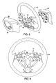
- FIG. 2 is a rear perspective view of the steering wheel shown in FIG. 1 ;
- FIG. 3 is a front perspective view of the steering wheel shown in FIG. 1 ;
- FIG. 4 is a side cross section view of the steering wheel taken along lines 4 - 4 of FIG. 3 ;
- FIG. 5 is an exploded perspective view of the steering wheel shown in FIG. 1 ;
- FIG. 6 is a front elevational view of the grip portion, the steering wheel armature and the central portion of the duct system of the steering wheel shown in FIG. 5 ;
- FIG. 7 is a front perspective view of the duct system and the steering wheel armature of FIG. 6 without the grip portion;
- FIG. 8 is a bottom view of the duct system and the steering wheel armature of FIG. 7 ;
- FIG. 9 is a side view of the duct system and the steering wheel armature of FIG. 7 ;
- FIG. 10 is an exploded rear perspective view of the duct system and the steering wheel armature of FIG. 7 ;
- FIG. 11 is an exploded front perspective view of the duct system and the steering wheel armature of FIG. 7 ;
- FIG. 12 is an enlarged view of the grip portion shown in FIG. 6 , with the duct system and the steering wheel armature shown in phantom;
- FIG. 13 is cross sectional view of the steering wheel taken along lines 13 - 13 of FIG. 12 ;
- FIG. 14 is an enlarged perspective view of the portion of the duct system configured to couple to the armature
- FIG. 15 illustrates the duct system coupled to the armature and disposed in a mold with an injection pump capable of forming the grip portion
- FIG. 16 is a flow chart illustrating the method of making the steering wheel according to one embodiment.
- a steering wheel 10 is illustrated in accordance with a first embodiment.
- the steering wheel 10 is disposed in the passenger compartment of a vehicle 100 .
- the passenger compartment is any suitable compartment and the steering wheel 10 is disposed within the compartment in any suitable manner.
- the steering wheel 10 is disposed adjacent the instrument panel IP as is known in the art, and operates the vehicle 100 in a conventional manner.
- the steering wheel 10 includes an armature 12 , a duct system 14 and a grip portion 16 .
- the armature 12 further includes a hub portion 17 and a ring portion 19 .
- the steering wheel 10 includes conventional components that enable the steering wheel 10 to operate the vehicle and function as a conventional steering wheel.
- the steering wheel 10 includes a central portion 18 , a peripheral portion 20 , and arms or spokes 22 that extend from the central portion 18 to the peripheral portion 22 .
- the central portion 18 houses an airbag (not shown) and can have radio, mobile phone, and/or any other suitable switches (not shown) to operate systems within the vehicle 100 .
- the air bag is configured to deploy out of a first side 24 of the central portion 18 so as to expand into the passenger compartment.
- a coupling member 28 enables the steering wheel 10 to be coupled to a steering column.
- an electrical harness or wiring can enter the second side 26 of the central portion 18 so as to enable operation of the switches or other mechanisms disposed on or in the steering wheel 10 .
- the spokes 22 and peripheral portion 20 can be covered with the grip portion 16 or any other suitable material disposed thereon.
- the duct system 14 forms openings 72 in an exterior surface 30 of the grip portion 16 of the steering wheel 10 , thus enabling air to be blown on the exterior surface 30 of the grip portion 16 (i.e., exterior surface of the steering wheel 10 ), cooling user hands and/or the exterior surface 30 of the grip portion 16 of the steering wheel 10 .
- the duct system 14 is coupled to the armature 12 so as to closely follow the contours thereof.
- the hub portion 17 includes a central portion 32 and arms 36 extending therefrom.
- the ring portion 19 extends through the hub portion 17 and defines a peripheral portion 34 of the armature 12 that links distal ends of the arms 36 .
- the armature 12 preferably is formed from steel or other suitable material.
- the center portion 32 can have any suitable configuration that would enable the steering wheel 10 to be connected to a steering column and include an airbag as well as any other suitable mechanisms or devices (e.g., wiring harness for radio and communication switches), as discussed herein.
- the central portion 32 includes an opening 38 in the center thereof so as to enable the steering wheel 10 to couple to the steering column, and includes a frame or structure that enables the central portion 18 of the steering wheel 10 to attach thereto.
- the hub portion 17 includes three (3) arms 36 , a first arm 36 a extending downwardly, a second arm 36 b extending to the left and a third arm 36 c extending to the right.
- Each of the arms 36 a , 36 b and 36 c extends radially outwardly from the central portion 32 to the peripheral portion 34 and rearwardly toward the passenger compartment, in any suitable manner.
- the central portion 32 of the hub portion 17 is arranged to enable the second side 26 of the center portion 18 of the steering wheel 10 to be recessed relative to the grip portion 16 , and enable the first side 24 of the steering wheel 10 to be generally coplanar or to protrude slightly in the rear direction from the grip portion 16 .
- the ring portion 19 is preferably generally circular and tubular. As is understood, the ring portion 19 is preferably a steel tube that generally forms a circle.
- the peripheral portion 34 can be hollow, solid or substantially solid or any combination thereof.
- the peripheral portion 34 can be formed in any suitable manner as is known in the art.
- the central portion 32 and the arms 36 of the hub portion 17 are preferably steel (or another suitable material) that is molded over the ring portion 19 .
- the armature 12 includes portions 34 a having a thicker diameter at an area on the peripheral portion 34 where the arms 36 connect the central portion 32 to the peripheral portion 34 . It is noted that although the peripheral portion 34 , the central portion 32 and arms 36 are illustrated with a specific configuration, the peripheral portion 34 , central portion 32 and arms 36 can be formed to have any configuration desired and be formed from any suitable material.
- the duct system 14 is preferably molded plastic and is configured to be coupled to the armature 12 .
- the duct system 14 preferably includes two fan boxes (i.e., a first fan box 40 and a second fan box 42 ), a peripheral duct section 44 and two connecting ducts or air passages 52 and 54 .
- the two fan boxes 40 and 42 are configured to house micro fans 48 and 50 .
- the micro fans 48 and 50 can be any suitable fan capable of communicating air from the fan boxes 40 and 42 to the grip portion 16 .
- the micro fans 48 and 50 are preferably electrically coupled to the electrical system in the vehicle 100 using a wiring harness.
- the micro fans 48 and 50 can use existing electrical wiring that extends to the steering wheel 10 (e.g., the wiring harness to operate the audio switches), or have dedicated electrical wiring. Additionally, the micro fans 48 and 50 can be powered in any manner desired, or can be any type of fan desired.
- the fan boxes 40 and 42 are attached to and communicate air through the air passages 52 and 54 .
- the air passages 52 and 54 fluidly connect the fan boxes 40 and 42 with the peripheral duct section 44 of the duct system 14 .
- the air passages 52 and 54 are generally hollow so as to enable air to pass therethrough. However, the air passages 52 and 54 can be any configuration that would enable air to pass therethrough and generally follow the contours of the arms 36 of the hub portion 17 .
- the peripheral duct section 44 of the duct system 14 is generally circular, such that it substantially surrounds the peripheral portion 34 of the armature 12 . That is, as shown in FIG.
- the duct system 14 encircles the peripheral portion 34 of the armature 12 ; however, the duct system 14 , in this embodiment, does not completely cover the peripheral portion 34 . In this embodiment, the duct system 14 does not cover the bottom area 34 a where the bottom arm 36 a of the hub portion 17 couples to the ring portion 19 .
- the peripheral duct section 44 is arcuate or includes an arcuate section, and the arcuate section extends more than 180 degrees about the periphery of the armature 12 .
- the peripheral duct section 44 can extend along the peripheral portion 34 of the armature 12 any distance desired, including completely covering the peripheral portion 34 of the armature 12 .
- the peripheral duct section 44 includes a base portion (e.g. a first portion) 56 and a plurality of nozzles (e.g., a second portion) 58 . That is, in one embodiment, the first portion of the duct system 14 is the base portion 56 and the second portion of the duct system 14 is the plurality of nozzles 58 . As illustrated in FIGS. 13 and 14 , the base portion 56 is generally tubular or circular. Thus, the base portion 56 has an arcuate portion that substantially surrounds the peripheral portion 34 of the armature 12 , such that the arcuate portion extends more than 180 degrees about an outer rounded contour of the armature 12 ( FIG. 13 ).
- the base portion forms a C-shape so as to have a first end 60 and a second end 62 , with a space or an opening 64 between the first end 60 and the second end 62 .
- This configuration enables the duct system 14 to snap-fit to the steering wheel armature 12 , holding the duct system 14 to the peripheral portion 34 of the armature 12 via a friction or interference fit.
- the base portion 56 is configured so as to extend along the armature 12 of the steering wheel 10 .
- the base portion 56 is generally hollow, defining an air passage therethrough.
- the base portion 56 is capable of communicating air or fluid from an air passage 66 around the armature 12 of the steering wheel 10 and to the plurality of nozzles 58 .
- the base portion 56 includes an arcuate portion and the plurality of nozzles 58 extend from the arcuate portion, the arcuate portion being configured to enable air to be communicated from the micro fans 48 and 50 to the plurality of nozzles 58 .
- the base portion 56 includes three (3) portions 56 a having an increased diameter. Each of these portions 56 a is arranged so as to coincide with the areas 34 a in which the arms 36 of the hub portion 17 couple to the ring portion 19 of the armature 12 .
- the plurality of nozzles 58 includes a first set of nozzles 58 a and a second set of nozzles 58 b , both of which extend from the exterior surface of the base portion 56 .
- the first set of nozzles 58 a extends in a first direction and the second set of nozzles 58 b extends in a second direction, the second direction being transverse to the first direction.
- the first set of nozzles 58 a extends radially outward relative to a rotational axis of the steering wheel 10
- the second set of nozzles 58 b extends substantially parallel to the rotational axis of the steering wheel 10 .
- the second set of nozzles 58 b extends normal to the exterior surface of the base portion 56 and forward toward a vehicle exterior.
- the first set of nozzles 58 a extends normal to the exterior surface of the base portion 56 and radially outwardly approximately 90° offset from the second set of nozzles 58 b .
- the nozzles 58 can be disposed in any position or in any manner desired.
- the nozzles 58 can also extend rearwardly toward the passenger compartment and/or inwardly toward the center of the steering wheel 10 .
- Each of the nozzles 58 is preferably substantially the same length and configured to extend to the exterior surface 30 of the grip portion 16 when the grip portion 16 is molded onto the armature 12 .
- Each of the nozzles 58 is connected to the base portion 56 at a first proximal end 70 and extends outwardly from the base portion 56 to a second distal end 72 .
- Each of the nozzles 58 is hollow with an opening 74 at the first end 70 and an opening 76 at the second end 72 .
- the nozzles 58 are configured so as to enable air to pass from the base portion 56 through the nozzles 58 and out of the opening 76 in the second end 72 .
- each of the nozzles 58 can have a frangible portion 78 that is configured to enable the second end 72 of the nozzles 58 to be removed subsequent to the over-molding process. That is, the frangible portion 78 is a thin walled portion adjacent the second end 72 of the nozzle 58 .
- the frangible portion 78 can be severed or broken, causing the second end 72 of the nozzle 58 to be substantially level with the exterior surface 30 of the grip portion 16 or below the level exterior surface 30 of the grip portion 16 , thus reducing potential contact between the nozzles 58 and the hands of a driver.
- the duct system 14 is coupled to the armature 12 basically by snapping the duct system 14 over the armature 12 .
- the duct system 14 is thus coupled to the armature 12 via a snap-fitting engagement in this embodiment.
- the duct system 14 can be coupled to the armature 12 in any manner desired.
- the armature 12 and the duct system 14 are then inserted into a mold 80 to form the grip portion 16 .
- the grip portion 16 is a polyurethane grip portion 16 ; however, the grip portion 16 can be formed from any suitable material.
- the mold 80 has an interior configuration that enables the grip portion 16 to be formed around the armature 12 and duct system 14 so as to conform to a predetermined shape.
- the mold 80 is generally an injection mold with a two piece form.
- the grip portion 16 is injected using an injection pump 82 with an injection nozzle 84 .
- the injection pump 82 , injection nozzle 84 and mold 50 are conventional devices and are therefore not discussed in detail. If desired, multiple injection pumps may be used.
- Walls of the mold 80 can optionally include recesses that receive the second ends 72 of the nozzles 58 such that the second ends 72 of the nozzles 58 are exposed and can be more easily separated from the duct system 14 at the frangible portions 78 after the grip portion 16 is formed.
- FIG. 16 illustrates one method of forming a cooling system for a steering wheel 10 .
- the first step is forming the duct system 14 including a plurality of nozzles 58 .
- the duct system 14 can be formed from at least one of plastic and stamped steel.
- the duct system 14 can include a first portion 56 and a second portion 58 , the second portion 58 including a plurality of nozzles 58 extending radially from the outer surface of the first portion 56 toward an outer surface of the steering wheel 10 .
- a frangible section 58 is formed on each of the plurality of nozzles 58 so as to be disposed below an exterior surface 30 of the grip portion 16 after the over-molding process.
- the steering wheel armature 12 can be formed as described herein, via a metal or other suitable material molding process. Since such a process is known, it is not discussed in detail herein.
- the duct system 14 is coupled to the armature 12 of the steering wheel 10 , preferably by snap-fitting the duct system 14 so as to overlie the armature 12 .
- the duct system 14 is configured to be coupled to the exterior surface 12 a of the armature 12 prior to a grip portion 16 over-molding process, so as to extend along the armature 12 . That is, as is illustrated, after the duct system 14 is coupled to the armature 12 , the combination of the duct system 14 and the armature 12 is positioned in a mold 80 and the grip portion 16 is formed by injection molding, so as to over-mold a grip portion 16 around the duct system 14 .
- the steering wheel 10 is removed, and if necessary, the second ends 72 of the nozzles 58 are removed. That is, if the second ends 72 of the nozzles 58 are in an undesirable position (e.g., extending above the exterior surface 30 of the grip portion 16 ), the second ends 72 can be removed.
- the second ends 72 can be removed in any suitable manner, including separation at the frangible portions 78 as described herein.
- the plurality of nozzles 58 is configured to enable openings 76 to be formed in the exterior surface 30 of the grip portion 16 , which is formed by an over-molding process.
- a leather grip or other exterior covering may be applied to the exterior surface 30 of the grip portion 16 , as long as such an exterior covering enables air to pass therethrough and adequately cool the surface of the steering wheel 10 and/or the driver.
- This configuration enables the duct system 14 to provide or move air from the micro fans 48 and 50 to the surface 30 of the grip portion 16 , providing a cooled surface and/or providing air to the surfaces of a driver's hands or body.
- the cooling system for a steering wheel 10 described herein is effective, cost efficient and easy to manufacture.
- the steering wheel airbag, steering column connection, and control devices for operating system are conventional components that are well known in the art. Since steering wheel airbags, steering column connections and control devices are well known in the art, these structures will not be discussed or illustrated in detail herein. Rather, it will be apparent to those skilled in the art from this disclosure that the components can be any type of structure and/or programming that can be used to carry out the present invention.
- the term “comprising” and its derivatives, as used herein, are intended to be open ended terms that specify the presence of the stated features, elements, components, groups, integers, and/or steps, but do not exclude the presence of other unstated features, elements, components, groups, integers and/or steps.
- the foregoing also applies to words having similar meanings such as the terms, “including”, “having” and their derivatives.
- the terms “part,” “section,” “portion,” “member” or “element” when used in the singular can have the dual meaning of a single part or a plurality of parts.
- the following directional terms “forward”, “rearward”, “above”, “downward”, “below” and “transverse” as well as any other similar directional terms refer to those directions of a vehicle equipped with the system for cooling a steering wheel and a method of making. Accordingly, these terms, as utilized to describe the present invention should be interpreted relative to a vehicle equipped with the system for cooling a steering wheel and a method of making.
Landscapes
- Engineering & Computer Science (AREA)
- Mechanical Engineering (AREA)
- Chemical & Material Sciences (AREA)
- Combustion & Propulsion (AREA)
- Transportation (AREA)
- Power Engineering (AREA)
- Physics & Mathematics (AREA)
- Thermal Sciences (AREA)
- Steering Controls (AREA)
Abstract
Description
Claims (20)
Priority Applications (1)
| Application Number | Priority Date | Filing Date | Title |
|---|---|---|---|
| US14/322,095 US9033366B1 (en) | 2014-07-02 | 2014-07-02 | System for cooling a steering wheel and a method of making |
Applications Claiming Priority (1)
| Application Number | Priority Date | Filing Date | Title |
|---|---|---|---|
| US14/322,095 US9033366B1 (en) | 2014-07-02 | 2014-07-02 | System for cooling a steering wheel and a method of making |
Publications (1)
| Publication Number | Publication Date |
|---|---|
| US9033366B1 true US9033366B1 (en) | 2015-05-19 |
Family
ID=53054554
Family Applications (1)
| Application Number | Title | Priority Date | Filing Date |
|---|---|---|---|
| US14/322,095 Active US9033366B1 (en) | 2014-07-02 | 2014-07-02 | System for cooling a steering wheel and a method of making |
Country Status (1)
| Country | Link |
|---|---|
| US (1) | US9033366B1 (en) |
Cited By (3)
| Publication number | Priority date | Publication date | Assignee | Title |
|---|---|---|---|---|
| CN105109542A (en) * | 2015-08-15 | 2015-12-02 | 苏州黄章妹族工业设计有限公司 | Intelligent-touch-screen symmetric type automobile steering wheel |
| WO2018052873A1 (en) | 2016-09-16 | 2018-03-22 | Key Safety Systems, Inc. | Climate controlled steering wheel |
| EP4509388A1 (en) | 2023-08-16 | 2025-02-19 | Van Eijndhoven, Bram | Steering wheel ventilation system |
Citations (19)
| Publication number | Priority date | Publication date | Assignee | Title |
|---|---|---|---|---|
| US1615635A (en) * | 1926-05-17 | 1927-01-25 | Kuno Shichigoro | Heating steering wheel |
| JPS6118562A (en) | 1984-07-04 | 1986-01-27 | Masatoshi Noguchi | Steering wheel for automobile having delivery hole at grip section |
| US4640340A (en) | 1983-10-21 | 1987-02-03 | Toyoda Gosei Co., Ltd. | Heated or cooled steering wheel |
| JPH02293255A (en) | 1989-05-02 | 1990-12-04 | Hisashi Yamaguchi | Steering wheel for automobile |
| JPH0466335A (en) | 1990-07-05 | 1992-03-02 | Hoomaa Ion Kenkyusho:Kk | Device for preventing driving car asleep |
| US5850741A (en) | 1997-06-09 | 1998-12-22 | Feher; Steve | Automotive vehicle steering wheel heating and cooling apparatus |
| US6298750B1 (en) | 1998-08-25 | 2001-10-09 | Daimlerchysler Ag | Steering wheel for a motor vehicle, and a method for producing a steering wheel rim |
| US6481312B1 (en) * | 1998-10-06 | 2002-11-19 | Trw Automotive Safety Systems Gmbh & Co. Kg | Ventilated steering wheel |
| US6509552B1 (en) * | 2002-03-05 | 2003-01-21 | Edward K. Roske | Temperature-controlled steering wheel |
| US6533184B1 (en) | 1999-10-18 | 2003-03-18 | Kiwan Kim | Comfort steering wheel |
| US20040168540A1 (en) * | 2003-01-08 | 2004-09-02 | Michael Weiss | Steering device with cooling device |
| US6862807B2 (en) * | 2000-12-08 | 2005-03-08 | Trw Automotive Safety Systems Gmbh & Co. Kg | Method of producing a steering wheel skeleton and vehicle steering wheel |
| USD559158S1 (en) * | 2006-11-11 | 2008-01-08 | Garcia Jose J | Heated and cooled steering wheel |
| US20090007721A1 (en) | 2007-07-06 | 2009-01-08 | Cortina Roger M | Steering Wheel with Modular Rim Assembly |
| US20090114368A1 (en) * | 2007-11-02 | 2009-05-07 | Minoru Niwa | Heated or cooled steering wheel |
| US7908941B2 (en) * | 2003-06-24 | 2011-03-22 | Key Safety Systems, Inc. | Heated and cooled steering wheel |
| US20110084055A1 (en) | 2009-10-08 | 2011-04-14 | Hyundai Motor Company | Steering wheel-heating system and method of heating steering wheel |
| US20130180354A1 (en) | 2012-01-12 | 2013-07-18 | Ford Global Technologies, Llc | Heated/cooled thermoelectric steering wheel |
| US20140090513A1 (en) * | 2012-09-28 | 2014-04-03 | W.E.T. Automotive Systems Ag | Heating and cooling device for handles, especially of steering mechanisms |
-
2014
- 2014-07-02 US US14/322,095 patent/US9033366B1/en active Active
Patent Citations (19)
| Publication number | Priority date | Publication date | Assignee | Title |
|---|---|---|---|---|
| US1615635A (en) * | 1926-05-17 | 1927-01-25 | Kuno Shichigoro | Heating steering wheel |
| US4640340A (en) | 1983-10-21 | 1987-02-03 | Toyoda Gosei Co., Ltd. | Heated or cooled steering wheel |
| JPS6118562A (en) | 1984-07-04 | 1986-01-27 | Masatoshi Noguchi | Steering wheel for automobile having delivery hole at grip section |
| JPH02293255A (en) | 1989-05-02 | 1990-12-04 | Hisashi Yamaguchi | Steering wheel for automobile |
| JPH0466335A (en) | 1990-07-05 | 1992-03-02 | Hoomaa Ion Kenkyusho:Kk | Device for preventing driving car asleep |
| US5850741A (en) | 1997-06-09 | 1998-12-22 | Feher; Steve | Automotive vehicle steering wheel heating and cooling apparatus |
| US6298750B1 (en) | 1998-08-25 | 2001-10-09 | Daimlerchysler Ag | Steering wheel for a motor vehicle, and a method for producing a steering wheel rim |
| US6481312B1 (en) * | 1998-10-06 | 2002-11-19 | Trw Automotive Safety Systems Gmbh & Co. Kg | Ventilated steering wheel |
| US6533184B1 (en) | 1999-10-18 | 2003-03-18 | Kiwan Kim | Comfort steering wheel |
| US6862807B2 (en) * | 2000-12-08 | 2005-03-08 | Trw Automotive Safety Systems Gmbh & Co. Kg | Method of producing a steering wheel skeleton and vehicle steering wheel |
| US6509552B1 (en) * | 2002-03-05 | 2003-01-21 | Edward K. Roske | Temperature-controlled steering wheel |
| US20040168540A1 (en) * | 2003-01-08 | 2004-09-02 | Michael Weiss | Steering device with cooling device |
| US7908941B2 (en) * | 2003-06-24 | 2011-03-22 | Key Safety Systems, Inc. | Heated and cooled steering wheel |
| USD559158S1 (en) * | 2006-11-11 | 2008-01-08 | Garcia Jose J | Heated and cooled steering wheel |
| US20090007721A1 (en) | 2007-07-06 | 2009-01-08 | Cortina Roger M | Steering Wheel with Modular Rim Assembly |
| US20090114368A1 (en) * | 2007-11-02 | 2009-05-07 | Minoru Niwa | Heated or cooled steering wheel |
| US20110084055A1 (en) | 2009-10-08 | 2011-04-14 | Hyundai Motor Company | Steering wheel-heating system and method of heating steering wheel |
| US20130180354A1 (en) | 2012-01-12 | 2013-07-18 | Ford Global Technologies, Llc | Heated/cooled thermoelectric steering wheel |
| US20140090513A1 (en) * | 2012-09-28 | 2014-04-03 | W.E.T. Automotive Systems Ag | Heating and cooling device for handles, especially of steering mechanisms |
Cited By (4)
| Publication number | Priority date | Publication date | Assignee | Title |
|---|---|---|---|---|
| CN105109542A (en) * | 2015-08-15 | 2015-12-02 | 苏州黄章妹族工业设计有限公司 | Intelligent-touch-screen symmetric type automobile steering wheel |
| WO2018052873A1 (en) | 2016-09-16 | 2018-03-22 | Key Safety Systems, Inc. | Climate controlled steering wheel |
| EP4509388A1 (en) | 2023-08-16 | 2025-02-19 | Van Eijndhoven, Bram | Steering wheel ventilation system |
| NL2035616B1 (en) | 2023-08-16 | 2025-02-28 | Van Eijndhoven Bram | Steering wheel ventilation system |
Similar Documents
| Publication | Publication Date | Title |
|---|---|---|
| US9173249B2 (en) | Steering wheel | |
| USD600595S1 (en) | Motor vehicle and toy replica thereof | |
| US11072358B2 (en) | Steering wheel covering member, steering wheel, and method for manufacturing steering wheel | |
| US6257615B1 (en) | Impact protection device | |
| US9033366B1 (en) | System for cooling a steering wheel and a method of making | |
| US6298750B1 (en) | Steering wheel for a motor vehicle, and a method for producing a steering wheel rim | |
| KR102036672B1 (en) | Steering wheel for vehicle | |
| USD986774S1 (en) | All-steel electric and gasoline agricultural all-terrain vehicle | |
| US10358160B2 (en) | Steering wheel | |
| USD1001028S1 (en) | Rear spoiler for motor vehicle | |
| JP6230698B2 (en) | Vehicle steering wheel | |
| US20120242065A1 (en) | Airbag cover | |
| US20170259840A1 (en) | Steering wheel | |
| US9073508B1 (en) | Driver airbag to steering wheel gap reduction | |
| US6164690A (en) | Steering wheel | |
| JPH11342851A (en) | Steering wheel | |
| US8166846B2 (en) | Steering handle | |
| USD892008S1 (en) | Rear spoiler for a vehicle | |
| JP2007508987A (en) | Steering wheel for cars | |
| US7674164B2 (en) | Air-conditioning system for the passenger compartment of a vehicle | |
| US10814699B2 (en) | Steering wheel and motor vehicle | |
| US20190263440A1 (en) | Climate controlled steering wheel | |
| JP6208075B2 (en) | Steering | |
| JPS62128878A (en) | Steering wheel | |
| US6231074B1 (en) | Steering wheel |
Legal Events
| Date | Code | Title | Description |
|---|---|---|---|
| AS | Assignment |
Owner name: NISSAN NORTH AMERICA, INC., TENNESSEE Free format text: ASSIGNMENT OF ASSIGNORS INTEREST;ASSIGNOR:DOWNEY, BRIAN;REEL/FRAME:033230/0796 Effective date: 20140702 |
|
| STCF | Information on status: patent grant |
Free format text: PATENTED CASE |
|
| AS | Assignment |
Owner name: NISSAN MOTOR CO., LTD., JAPAN Free format text: ASSIGNMENT OF ASSIGNORS INTEREST;ASSIGNOR:NISSAN NORTH AMERICA, INC.;REEL/FRAME:036456/0497 Effective date: 20150821 |
|
| MAFP | Maintenance fee payment |
Free format text: PAYMENT OF MAINTENANCE FEE, 4TH YEAR, LARGE ENTITY (ORIGINAL EVENT CODE: M1551); ENTITY STATUS OF PATENT OWNER: LARGE ENTITY Year of fee payment: 4 |
|
| MAFP | Maintenance fee payment |
Free format text: PAYMENT OF MAINTENANCE FEE, 8TH YEAR, LARGE ENTITY (ORIGINAL EVENT CODE: M1552); ENTITY STATUS OF PATENT OWNER: LARGE ENTITY Year of fee payment: 8 |