US9066435B2 - Wiring board and method for manufacturing the same - Google Patents
Wiring board and method for manufacturing the same Download PDFInfo
- Publication number
- US9066435B2 US9066435B2 US13/853,227 US201313853227A US9066435B2 US 9066435 B2 US9066435 B2 US 9066435B2 US 201313853227 A US201313853227 A US 201313853227A US 9066435 B2 US9066435 B2 US 9066435B2
- Authority
- US
- United States
- Prior art keywords
- insulation layer
- conductive patterns
- wiring board
- wiring
- wiring structure
- Prior art date
- Legal status (The legal status is an assumption and is not a legal conclusion. Google has not performed a legal analysis and makes no representation as to the accuracy of the status listed.)
- Active, expires
Links
- 238000004519 manufacturing process Methods 0.000 title description 59
- 238000000034 method Methods 0.000 title description 59
- 238000009413 insulation Methods 0.000 claims abstract description 188
- 239000004020 conductor Substances 0.000 claims abstract description 75
- 239000010410 layer Substances 0.000 claims description 281
- 239000004065 semiconductor Substances 0.000 claims description 43
- 239000012790 adhesive layer Substances 0.000 claims description 27
- 230000000149 penetrating effect Effects 0.000 claims description 12
- 239000000758 substrate Substances 0.000 description 61
- 239000011229 interlayer Substances 0.000 description 60
- 239000011162 core material Substances 0.000 description 51
- RYGMFSIKBFXOCR-UHFFFAOYSA-N Copper Chemical compound [Cu] RYGMFSIKBFXOCR-UHFFFAOYSA-N 0.000 description 50
- 239000010408 film Substances 0.000 description 28
- 229910000679 solder Inorganic materials 0.000 description 24
- 230000008569 process Effects 0.000 description 21
- 229920005989 resin Polymers 0.000 description 16
- 239000011347 resin Substances 0.000 description 16
- 239000000463 material Substances 0.000 description 13
- 239000011521 glass Substances 0.000 description 9
- 239000004744 fabric Substances 0.000 description 8
- 238000005259 measurement Methods 0.000 description 8
- 238000007747 plating Methods 0.000 description 8
- 230000008054 signal transmission Effects 0.000 description 7
- 238000013461 design Methods 0.000 description 5
- 238000009429 electrical wiring Methods 0.000 description 5
- 239000003822 epoxy resin Substances 0.000 description 5
- 238000005530 etching Methods 0.000 description 5
- XLYOFNOQVPJJNP-UHFFFAOYSA-M hydroxide Chemical compound [OH-] XLYOFNOQVPJJNP-UHFFFAOYSA-M 0.000 description 5
- 229910052751 metal Inorganic materials 0.000 description 5
- 239000002184 metal Substances 0.000 description 5
- 239000011295 pitch Substances 0.000 description 5
- 229920000647 polyepoxide Polymers 0.000 description 5
- KDLHZDBZIXYQEI-UHFFFAOYSA-N Palladium Chemical compound [Pd] KDLHZDBZIXYQEI-UHFFFAOYSA-N 0.000 description 4
- 239000000853 adhesive Substances 0.000 description 4
- 230000001070 adhesive effect Effects 0.000 description 4
- 239000011889 copper foil Substances 0.000 description 4
- 238000003475 lamination Methods 0.000 description 4
- 230000004048 modification Effects 0.000 description 4
- 238000012986 modification Methods 0.000 description 4
- HEMHJVSKTPXQMS-UHFFFAOYSA-M Sodium hydroxide Chemical compound [OH-].[Na+] HEMHJVSKTPXQMS-UHFFFAOYSA-M 0.000 description 3
- 230000008901 benefit Effects 0.000 description 3
- 239000010949 copper Substances 0.000 description 3
- 238000007772 electroless plating Methods 0.000 description 3
- 238000012545 processing Methods 0.000 description 3
- 239000012779 reinforcing material Substances 0.000 description 3
- 239000002344 surface layer Substances 0.000 description 3
- NIXOWILDQLNWCW-UHFFFAOYSA-N Acrylic acid Chemical compound OC(=O)C=C NIXOWILDQLNWCW-UHFFFAOYSA-N 0.000 description 2
- 239000004925 Acrylic resin Substances 0.000 description 2
- 229920000178 Acrylic resin Polymers 0.000 description 2
- PXHVJJICTQNCMI-UHFFFAOYSA-N Nickel Chemical compound [Ni] PXHVJJICTQNCMI-UHFFFAOYSA-N 0.000 description 2
- 229910008433 SnCU Inorganic materials 0.000 description 2
- 239000000654 additive Substances 0.000 description 2
- 239000003054 catalyst Substances 0.000 description 2
- 238000005229 chemical vapour deposition Methods 0.000 description 2
- 230000007423 decrease Effects 0.000 description 2
- 239000011152 fibreglass Substances 0.000 description 2
- 229910052737 gold Inorganic materials 0.000 description 2
- 239000010931 gold Substances 0.000 description 2
- MSNOMDLPLDYDME-UHFFFAOYSA-N gold nickel Chemical compound [Ni].[Au] MSNOMDLPLDYDME-UHFFFAOYSA-N 0.000 description 2
- 230000001678 irradiating effect Effects 0.000 description 2
- 238000010030 laminating Methods 0.000 description 2
- 230000003647 oxidation Effects 0.000 description 2
- 238000007254 oxidation reaction Methods 0.000 description 2
- 229910052763 palladium Inorganic materials 0.000 description 2
- 238000005240 physical vapour deposition Methods 0.000 description 2
- 239000003755 preservative agent Substances 0.000 description 2
- 230000002335 preservative effect Effects 0.000 description 2
- 229920002050 silicone resin Polymers 0.000 description 2
- 230000004580 weight loss Effects 0.000 description 2
- JYEUMXHLPRZUAT-UHFFFAOYSA-N 1,2,3-triazine Chemical compound C1=CN=NN=C1 JYEUMXHLPRZUAT-UHFFFAOYSA-N 0.000 description 1
- XQUPVDVFXZDTLT-UHFFFAOYSA-N 1-[4-[[4-(2,5-dioxopyrrol-1-yl)phenyl]methyl]phenyl]pyrrole-2,5-dione Chemical compound O=C1C=CC(=O)N1C(C=C1)=CC=C1CC1=CC=C(N2C(C=CC2=O)=O)C=C1 XQUPVDVFXZDTLT-UHFFFAOYSA-N 0.000 description 1
- HZAXFHJVJLSVMW-UHFFFAOYSA-N 2-Aminoethan-1-ol Chemical compound NCCO HZAXFHJVJLSVMW-UHFFFAOYSA-N 0.000 description 1
- 239000004642 Polyimide Substances 0.000 description 1
- 239000006087 Silane Coupling Agent Substances 0.000 description 1
- ATJFFYVFTNAWJD-UHFFFAOYSA-N Tin Chemical compound [Sn] ATJFFYVFTNAWJD-UHFFFAOYSA-N 0.000 description 1
- 230000002159 abnormal effect Effects 0.000 description 1
- 239000002253 acid Substances 0.000 description 1
- WNROFYMDJYEPJX-UHFFFAOYSA-K aluminium hydroxide Chemical compound [OH-].[OH-].[OH-].[Al+3] WNROFYMDJYEPJX-UHFFFAOYSA-K 0.000 description 1
- 239000004760 aramid Substances 0.000 description 1
- 229920003235 aromatic polyamide Polymers 0.000 description 1
- RQPZNWPYLFFXCP-UHFFFAOYSA-L barium dihydroxide Chemical compound [OH-].[OH-].[Ba+2] RQPZNWPYLFFXCP-UHFFFAOYSA-L 0.000 description 1
- 229910001863 barium hydroxide Inorganic materials 0.000 description 1
- AXCZMVOFGPJBDE-UHFFFAOYSA-L calcium dihydroxide Chemical compound [OH-].[OH-].[Ca+2] AXCZMVOFGPJBDE-UHFFFAOYSA-L 0.000 description 1
- 239000000920 calcium hydroxide Substances 0.000 description 1
- 229910001861 calcium hydroxide Inorganic materials 0.000 description 1
- 238000004140 cleaning Methods 0.000 description 1
- 229910052802 copper Inorganic materials 0.000 description 1
- 238000005520 cutting process Methods 0.000 description 1
- 230000003247 decreasing effect Effects 0.000 description 1
- 230000007547 defect Effects 0.000 description 1
- 238000009826 distribution Methods 0.000 description 1
- 230000000694 effects Effects 0.000 description 1
- 238000009713 electroplating Methods 0.000 description 1
- 239000011888 foil Substances 0.000 description 1
- 230000006870 function Effects 0.000 description 1
- 238000010438 heat treatment Methods 0.000 description 1
- VTHJTEIRLNZDEV-UHFFFAOYSA-L magnesium dihydroxide Chemical compound [OH-].[OH-].[Mg+2] VTHJTEIRLNZDEV-UHFFFAOYSA-L 0.000 description 1
- 239000000347 magnesium hydroxide Substances 0.000 description 1
- 229910001862 magnesium hydroxide Inorganic materials 0.000 description 1
- 229910000000 metal hydroxide Inorganic materials 0.000 description 1
- 150000004692 metal hydroxides Chemical class 0.000 description 1
- 229910052759 nickel Inorganic materials 0.000 description 1
- 239000007800 oxidant agent Substances 0.000 description 1
- 230000001590 oxidative effect Effects 0.000 description 1
- 239000002245 particle Substances 0.000 description 1
- 239000005011 phenolic resin Substances 0.000 description 1
- 238000000206 photolithography Methods 0.000 description 1
- 229920003192 poly(bis maleimide) Polymers 0.000 description 1
- 229920002577 polybenzoxazole Polymers 0.000 description 1
- 229920001721 polyimide Polymers 0.000 description 1
- 229910052710 silicon Inorganic materials 0.000 description 1
- 239000010703 silicon Substances 0.000 description 1
- UKLNMMHNWFDKNT-UHFFFAOYSA-M sodium chlorite Chemical compound [Na+].[O-]Cl=O UKLNMMHNWFDKNT-UHFFFAOYSA-M 0.000 description 1
- 238000004544 sputter deposition Methods 0.000 description 1
- 238000007669 thermal treatment Methods 0.000 description 1
- 239000010409 thin film Substances 0.000 description 1
- RYFMWSXOAZQYPI-UHFFFAOYSA-K trisodium phosphate Chemical compound [Na+].[Na+].[Na+].[O-]P([O-])([O-])=O RYFMWSXOAZQYPI-UHFFFAOYSA-K 0.000 description 1
- 229910000406 trisodium phosphate Inorganic materials 0.000 description 1
- XLYOFNOQVPJJNP-UHFFFAOYSA-N water Substances O XLYOFNOQVPJJNP-UHFFFAOYSA-N 0.000 description 1
Images


Classifications
-
- H—ELECTRICITY
- H05—ELECTRIC TECHNIQUES NOT OTHERWISE PROVIDED FOR
- H05K—PRINTED CIRCUITS; CASINGS OR CONSTRUCTIONAL DETAILS OF ELECTRIC APPARATUS; MANUFACTURE OF ASSEMBLAGES OF ELECTRICAL COMPONENTS
- H05K3/00—Apparatus or processes for manufacturing printed circuits
- H05K3/30—Assembling printed circuits with electric components, e.g. with resistor
- H05K3/303—Surface mounted components, e.g. affixing before soldering, aligning means, spacing means
- H05K3/305—Affixing by adhesive
-
- H—ELECTRICITY
- H05—ELECTRIC TECHNIQUES NOT OTHERWISE PROVIDED FOR
- H05K—PRINTED CIRCUITS; CASINGS OR CONSTRUCTIONAL DETAILS OF ELECTRIC APPARATUS; MANUFACTURE OF ASSEMBLAGES OF ELECTRICAL COMPONENTS
- H05K1/00—Printed circuits
- H05K1/02—Details
- H05K1/11—Printed elements for providing electric connections to or between printed circuits
- H05K1/115—Via connections; Lands around holes or via connections
-
- H—ELECTRICITY
- H01—ELECTRIC ELEMENTS
- H01L—SEMICONDUCTOR DEVICES NOT COVERED BY CLASS H10
- H01L21/00—Processes or apparatus adapted for the manufacture or treatment of semiconductor or solid state devices or of parts thereof
- H01L21/02—Manufacture or treatment of semiconductor devices or of parts thereof
- H01L21/04—Manufacture or treatment of semiconductor devices or of parts thereof the devices having at least one potential-jump barrier or surface barrier, e.g. PN junction, depletion layer or carrier concentration layer
- H01L21/50—Assembly of semiconductor devices using processes or apparatus not provided for in a single one of the subgroups H01L21/06 - H01L21/326, e.g. sealing of a cap to a base of a container
- H01L21/56—Encapsulations, e.g. encapsulation layers, coatings
- H01L21/563—Encapsulation of active face of flip-chip device, e.g. underfilling or underencapsulation of flip-chip, encapsulation preform on chip or mounting substrate
-
- H—ELECTRICITY
- H01—ELECTRIC ELEMENTS
- H01L—SEMICONDUCTOR DEVICES NOT COVERED BY CLASS H10
- H01L23/00—Details of semiconductor or other solid state devices
- H01L23/48—Arrangements for conducting electric current to or from the solid state body in operation, e.g. leads, terminal arrangements ; Selection of materials therefor
- H01L23/488—Arrangements for conducting electric current to or from the solid state body in operation, e.g. leads, terminal arrangements ; Selection of materials therefor consisting of soldered or bonded constructions
- H01L23/498—Leads, i.e. metallisations or lead-frames on insulating substrates, e.g. chip carriers
- H01L23/49811—Additional leads joined to the metallisation on the insulating substrate, e.g. pins, bumps, wires, flat leads
- H01L23/49816—Spherical bumps on the substrate for external connection, e.g. ball grid arrays [BGA]
-
- H—ELECTRICITY
- H01—ELECTRIC ELEMENTS
- H01L—SEMICONDUCTOR DEVICES NOT COVERED BY CLASS H10
- H01L23/00—Details of semiconductor or other solid state devices
- H01L23/48—Arrangements for conducting electric current to or from the solid state body in operation, e.g. leads, terminal arrangements ; Selection of materials therefor
- H01L23/488—Arrangements for conducting electric current to or from the solid state body in operation, e.g. leads, terminal arrangements ; Selection of materials therefor consisting of soldered or bonded constructions
- H01L23/498—Leads, i.e. metallisations or lead-frames on insulating substrates, e.g. chip carriers
- H01L23/49827—Via connections through the substrates, e.g. pins going through the substrate, coaxial cables
-
- H—ELECTRICITY
- H01—ELECTRIC ELEMENTS
- H01L—SEMICONDUCTOR DEVICES NOT COVERED BY CLASS H10
- H01L23/00—Details of semiconductor or other solid state devices
- H01L23/52—Arrangements for conducting electric current within the device in operation from one component to another, i.e. interconnections, e.g. wires, lead frames
- H01L23/538—Arrangements for conducting electric current within the device in operation from one component to another, i.e. interconnections, e.g. wires, lead frames the interconnection structure between a plurality of semiconductor chips being formed on, or in, insulating substrates
- H01L23/5382—Adaptable interconnections, e.g. for engineering changes
-
- H—ELECTRICITY
- H01—ELECTRIC ELEMENTS
- H01L—SEMICONDUCTOR DEVICES NOT COVERED BY CLASS H10
- H01L23/00—Details of semiconductor or other solid state devices
- H01L23/52—Arrangements for conducting electric current within the device in operation from one component to another, i.e. interconnections, e.g. wires, lead frames
- H01L23/538—Arrangements for conducting electric current within the device in operation from one component to another, i.e. interconnections, e.g. wires, lead frames the interconnection structure between a plurality of semiconductor chips being formed on, or in, insulating substrates
- H01L23/5383—Multilayer substrates
-
- H—ELECTRICITY
- H01—ELECTRIC ELEMENTS
- H01L—SEMICONDUCTOR DEVICES NOT COVERED BY CLASS H10
- H01L23/00—Details of semiconductor or other solid state devices
- H01L23/52—Arrangements for conducting electric current within the device in operation from one component to another, i.e. interconnections, e.g. wires, lead frames
- H01L23/538—Arrangements for conducting electric current within the device in operation from one component to another, i.e. interconnections, e.g. wires, lead frames the interconnection structure between a plurality of semiconductor chips being formed on, or in, insulating substrates
- H01L23/5384—Conductive vias through the substrate with or without pins, e.g. buried coaxial conductors
-
- H—ELECTRICITY
- H01—ELECTRIC ELEMENTS
- H01L—SEMICONDUCTOR DEVICES NOT COVERED BY CLASS H10
- H01L24/00—Arrangements for connecting or disconnecting semiconductor or solid-state bodies; Methods or apparatus related thereto
- H01L24/01—Means for bonding being attached to, or being formed on, the surface to be connected, e.g. chip-to-package, die-attach, "first-level" interconnects; Manufacturing methods related thereto
- H01L24/02—Bonding areas ; Manufacturing methods related thereto
- H01L24/03—Manufacturing methods
-
- H—ELECTRICITY
- H01—ELECTRIC ELEMENTS
- H01L—SEMICONDUCTOR DEVICES NOT COVERED BY CLASS H10
- H01L24/00—Arrangements for connecting or disconnecting semiconductor or solid-state bodies; Methods or apparatus related thereto
- H01L24/80—Methods for connecting semiconductor or other solid state bodies using means for bonding being attached to, or being formed on, the surface to be connected
- H01L24/81—Methods for connecting semiconductor or other solid state bodies using means for bonding being attached to, or being formed on, the surface to be connected using a bump connector
-
- H—ELECTRICITY
- H01—ELECTRIC ELEMENTS
- H01L—SEMICONDUCTOR DEVICES NOT COVERED BY CLASS H10
- H01L25/00—Assemblies consisting of a plurality of individual semiconductor or other solid state devices ; Multistep manufacturing processes thereof
- H01L25/50—Multistep manufacturing processes of assemblies consisting of devices, each device being of a type provided for in group H01L27/00 or H01L29/00
-
- H—ELECTRICITY
- H05—ELECTRIC TECHNIQUES NOT OTHERWISE PROVIDED FOR
- H05K—PRINTED CIRCUITS; CASINGS OR CONSTRUCTIONAL DETAILS OF ELECTRIC APPARATUS; MANUFACTURE OF ASSEMBLAGES OF ELECTRICAL COMPONENTS
- H05K3/00—Apparatus or processes for manufacturing printed circuits
- H05K3/10—Apparatus or processes for manufacturing printed circuits in which conductive material is applied to the insulating support in such a manner as to form the desired conductive pattern
- H05K3/103—Apparatus or processes for manufacturing printed circuits in which conductive material is applied to the insulating support in such a manner as to form the desired conductive pattern by bonding or embedding conductive wires or strips
-
- H—ELECTRICITY
- H05—ELECTRIC TECHNIQUES NOT OTHERWISE PROVIDED FOR
- H05K—PRINTED CIRCUITS; CASINGS OR CONSTRUCTIONAL DETAILS OF ELECTRIC APPARATUS; MANUFACTURE OF ASSEMBLAGES OF ELECTRICAL COMPONENTS
- H05K3/00—Apparatus or processes for manufacturing printed circuits
- H05K3/10—Apparatus or processes for manufacturing printed circuits in which conductive material is applied to the insulating support in such a manner as to form the desired conductive pattern
- H05K3/20—Apparatus or processes for manufacturing printed circuits in which conductive material is applied to the insulating support in such a manner as to form the desired conductive pattern by affixing prefabricated conductor pattern
-
- H—ELECTRICITY
- H05—ELECTRIC TECHNIQUES NOT OTHERWISE PROVIDED FOR
- H05K—PRINTED CIRCUITS; CASINGS OR CONSTRUCTIONAL DETAILS OF ELECTRIC APPARATUS; MANUFACTURE OF ASSEMBLAGES OF ELECTRICAL COMPONENTS
- H05K3/00—Apparatus or processes for manufacturing printed circuits
- H05K3/30—Assembling printed circuits with electric components, e.g. with resistor
- H05K3/32—Assembling printed circuits with electric components, e.g. with resistor electrically connecting electric components or wires to printed circuits
-
- H—ELECTRICITY
- H05—ELECTRIC TECHNIQUES NOT OTHERWISE PROVIDED FOR
- H05K—PRINTED CIRCUITS; CASINGS OR CONSTRUCTIONAL DETAILS OF ELECTRIC APPARATUS; MANUFACTURE OF ASSEMBLAGES OF ELECTRICAL COMPONENTS
- H05K3/00—Apparatus or processes for manufacturing printed circuits
- H05K3/46—Manufacturing multilayer circuits
- H05K3/4644—Manufacturing multilayer circuits by building the multilayer layer by layer, i.e. build-up multilayer circuits
- H05K3/4652—Adding a circuit layer by laminating a metal foil or a preformed metal foil pattern
- H05K3/4658—Adding a circuit layer by laminating a metal foil or a preformed metal foil pattern characterized by laminating a prefabricated metal foil pattern, e.g. by transfer
-
- H—ELECTRICITY
- H05—ELECTRIC TECHNIQUES NOT OTHERWISE PROVIDED FOR
- H05K—PRINTED CIRCUITS; CASINGS OR CONSTRUCTIONAL DETAILS OF ELECTRIC APPARATUS; MANUFACTURE OF ASSEMBLAGES OF ELECTRICAL COMPONENTS
- H05K3/00—Apparatus or processes for manufacturing printed circuits
- H05K3/46—Manufacturing multilayer circuits
- H05K3/4688—Composite multilayer circuits, i.e. comprising insulating layers having different properties
- H05K3/4694—Partitioned multilayer circuits having adjacent regions with different properties, e.g. by adding or inserting locally circuit layers having a higher circuit density
-
- H—ELECTRICITY
- H01—ELECTRIC ELEMENTS
- H01L—SEMICONDUCTOR DEVICES NOT COVERED BY CLASS H10
- H01L2224/00—Indexing scheme for arrangements for connecting or disconnecting semiconductor or solid-state bodies and methods related thereto as covered by H01L24/00
- H01L2224/01—Means for bonding being attached to, or being formed on, the surface to be connected, e.g. chip-to-package, die-attach, "first-level" interconnects; Manufacturing methods related thereto
- H01L2224/02—Bonding areas; Manufacturing methods related thereto
- H01L2224/04—Structure, shape, material or disposition of the bonding areas prior to the connecting process
- H01L2224/0401—Bonding areas specifically adapted for bump connectors, e.g. under bump metallisation [UBM]
-
- H—ELECTRICITY
- H01—ELECTRIC ELEMENTS
- H01L—SEMICONDUCTOR DEVICES NOT COVERED BY CLASS H10
- H01L2224/00—Indexing scheme for arrangements for connecting or disconnecting semiconductor or solid-state bodies and methods related thereto as covered by H01L24/00
- H01L2224/01—Means for bonding being attached to, or being formed on, the surface to be connected, e.g. chip-to-package, die-attach, "first-level" interconnects; Manufacturing methods related thereto
- H01L2224/10—Bump connectors; Manufacturing methods related thereto
- H01L2224/12—Structure, shape, material or disposition of the bump connectors prior to the connecting process
- H01L2224/13—Structure, shape, material or disposition of the bump connectors prior to the connecting process of an individual bump connector
- H01L2224/13001—Core members of the bump connector
- H01L2224/13099—Material
- H01L2224/131—Material with a principal constituent of the material being a metal or a metalloid, e.g. boron [B], silicon [Si], germanium [Ge], arsenic [As], antimony [Sb], tellurium [Te] and polonium [Po], and alloys thereof
-
- H—ELECTRICITY
- H01—ELECTRIC ELEMENTS
- H01L—SEMICONDUCTOR DEVICES NOT COVERED BY CLASS H10
- H01L2224/00—Indexing scheme for arrangements for connecting or disconnecting semiconductor or solid-state bodies and methods related thereto as covered by H01L24/00
- H01L2224/01—Means for bonding being attached to, or being formed on, the surface to be connected, e.g. chip-to-package, die-attach, "first-level" interconnects; Manufacturing methods related thereto
- H01L2224/10—Bump connectors; Manufacturing methods related thereto
- H01L2224/15—Structure, shape, material or disposition of the bump connectors after the connecting process
- H01L2224/16—Structure, shape, material or disposition of the bump connectors after the connecting process of an individual bump connector
- H01L2224/161—Disposition
- H01L2224/16151—Disposition the bump connector connecting between a semiconductor or solid-state body and an item not being a semiconductor or solid-state body, e.g. chip-to-substrate, chip-to-passive
- H01L2224/16221—Disposition the bump connector connecting between a semiconductor or solid-state body and an item not being a semiconductor or solid-state body, e.g. chip-to-substrate, chip-to-passive the body and the item being stacked
- H01L2224/16225—Disposition the bump connector connecting between a semiconductor or solid-state body and an item not being a semiconductor or solid-state body, e.g. chip-to-substrate, chip-to-passive the body and the item being stacked the item being non-metallic, e.g. insulating substrate with or without metallisation
- H01L2224/16227—Disposition the bump connector connecting between a semiconductor or solid-state body and an item not being a semiconductor or solid-state body, e.g. chip-to-substrate, chip-to-passive the body and the item being stacked the item being non-metallic, e.g. insulating substrate with or without metallisation the bump connector connecting to a bond pad of the item
-
- H—ELECTRICITY
- H01—ELECTRIC ELEMENTS
- H01L—SEMICONDUCTOR DEVICES NOT COVERED BY CLASS H10
- H01L2224/00—Indexing scheme for arrangements for connecting or disconnecting semiconductor or solid-state bodies and methods related thereto as covered by H01L24/00
- H01L2224/01—Means for bonding being attached to, or being formed on, the surface to be connected, e.g. chip-to-package, die-attach, "first-level" interconnects; Manufacturing methods related thereto
- H01L2224/26—Layer connectors, e.g. plate connectors, solder or adhesive layers; Manufacturing methods related thereto
- H01L2224/31—Structure, shape, material or disposition of the layer connectors after the connecting process
- H01L2224/32—Structure, shape, material or disposition of the layer connectors after the connecting process of an individual layer connector
- H01L2224/321—Disposition
- H01L2224/32151—Disposition the layer connector connecting between a semiconductor or solid-state body and an item not being a semiconductor or solid-state body, e.g. chip-to-substrate, chip-to-passive
- H01L2224/32221—Disposition the layer connector connecting between a semiconductor or solid-state body and an item not being a semiconductor or solid-state body, e.g. chip-to-substrate, chip-to-passive the body and the item being stacked
- H01L2224/32225—Disposition the layer connector connecting between a semiconductor or solid-state body and an item not being a semiconductor or solid-state body, e.g. chip-to-substrate, chip-to-passive the body and the item being stacked the item being non-metallic, e.g. insulating substrate with or without metallisation
-
- H—ELECTRICITY
- H01—ELECTRIC ELEMENTS
- H01L—SEMICONDUCTOR DEVICES NOT COVERED BY CLASS H10
- H01L2224/00—Indexing scheme for arrangements for connecting or disconnecting semiconductor or solid-state bodies and methods related thereto as covered by H01L24/00
- H01L2224/73—Means for bonding being of different types provided for in two or more of groups H01L2224/10, H01L2224/18, H01L2224/26, H01L2224/34, H01L2224/42, H01L2224/50, H01L2224/63, H01L2224/71
- H01L2224/732—Location after the connecting process
- H01L2224/73201—Location after the connecting process on the same surface
- H01L2224/73203—Bump and layer connectors
- H01L2224/73204—Bump and layer connectors the bump connector being embedded into the layer connector
-
- H—ELECTRICITY
- H01—ELECTRIC ELEMENTS
- H01L—SEMICONDUCTOR DEVICES NOT COVERED BY CLASS H10
- H01L2224/00—Indexing scheme for arrangements for connecting or disconnecting semiconductor or solid-state bodies and methods related thereto as covered by H01L24/00
- H01L2224/80—Methods for connecting semiconductor or other solid state bodies using means for bonding being attached to, or being formed on, the surface to be connected
- H01L2224/81—Methods for connecting semiconductor or other solid state bodies using means for bonding being attached to, or being formed on, the surface to be connected using a bump connector
- H01L2224/8119—Arrangement of the bump connectors prior to mounting
- H01L2224/81192—Arrangement of the bump connectors prior to mounting wherein the bump connectors are disposed only on another item or body to be connected to the semiconductor or solid-state body
-
- H—ELECTRICITY
- H01—ELECTRIC ELEMENTS
- H01L—SEMICONDUCTOR DEVICES NOT COVERED BY CLASS H10
- H01L23/00—Details of semiconductor or other solid state devices
- H01L23/48—Arrangements for conducting electric current to or from the solid state body in operation, e.g. leads, terminal arrangements ; Selection of materials therefor
- H01L23/488—Arrangements for conducting electric current to or from the solid state body in operation, e.g. leads, terminal arrangements ; Selection of materials therefor consisting of soldered or bonded constructions
- H01L23/498—Leads, i.e. metallisations or lead-frames on insulating substrates, e.g. chip carriers
- H01L23/49866—Leads, i.e. metallisations or lead-frames on insulating substrates, e.g. chip carriers characterised by the materials
- H01L23/49894—Materials of the insulating layers or coatings
-
- H—ELECTRICITY
- H01—ELECTRIC ELEMENTS
- H01L—SEMICONDUCTOR DEVICES NOT COVERED BY CLASS H10
- H01L24/00—Arrangements for connecting or disconnecting semiconductor or solid-state bodies; Methods or apparatus related thereto
- H01L24/01—Means for bonding being attached to, or being formed on, the surface to be connected, e.g. chip-to-package, die-attach, "first-level" interconnects; Manufacturing methods related thereto
- H01L24/10—Bump connectors ; Manufacturing methods related thereto
- H01L24/15—Structure, shape, material or disposition of the bump connectors after the connecting process
- H01L24/16—Structure, shape, material or disposition of the bump connectors after the connecting process of an individual bump connector
-
- H—ELECTRICITY
- H01—ELECTRIC ELEMENTS
- H01L—SEMICONDUCTOR DEVICES NOT COVERED BY CLASS H10
- H01L2924/00—Indexing scheme for arrangements or methods for connecting or disconnecting semiconductor or solid-state bodies as covered by H01L24/00
-
- H—ELECTRICITY
- H01—ELECTRIC ELEMENTS
- H01L—SEMICONDUCTOR DEVICES NOT COVERED BY CLASS H10
- H01L2924/00—Indexing scheme for arrangements or methods for connecting or disconnecting semiconductor or solid-state bodies as covered by H01L24/00
- H01L2924/013—Alloys
- H01L2924/014—Solder alloys
-
- H—ELECTRICITY
- H01—ELECTRIC ELEMENTS
- H01L—SEMICONDUCTOR DEVICES NOT COVERED BY CLASS H10
- H01L2924/00—Indexing scheme for arrangements or methods for connecting or disconnecting semiconductor or solid-state bodies as covered by H01L24/00
- H01L2924/10—Details of semiconductor or other solid state devices to be connected
- H01L2924/11—Device type
- H01L2924/12—Passive devices, e.g. 2 terminal devices
- H01L2924/1204—Optical Diode
- H01L2924/12042—LASER
-
- H—ELECTRICITY
- H01—ELECTRIC ELEMENTS
- H01L—SEMICONDUCTOR DEVICES NOT COVERED BY CLASS H10
- H01L2924/00—Indexing scheme for arrangements or methods for connecting or disconnecting semiconductor or solid-state bodies as covered by H01L24/00
- H01L2924/10—Details of semiconductor or other solid state devices to be connected
- H01L2924/11—Device type
- H01L2924/14—Integrated circuits
- H01L2924/143—Digital devices
- H01L2924/1434—Memory
- H01L2924/1435—Random access memory [RAM]
- H01L2924/1436—Dynamic random-access memory [DRAM]
-
- H—ELECTRICITY
- H01—ELECTRIC ELEMENTS
- H01L—SEMICONDUCTOR DEVICES NOT COVERED BY CLASS H10
- H01L2924/00—Indexing scheme for arrangements or methods for connecting or disconnecting semiconductor or solid-state bodies as covered by H01L24/00
- H01L2924/15—Details of package parts other than the semiconductor or other solid state devices to be connected
- H01L2924/151—Die mounting substrate
- H01L2924/1517—Multilayer substrate
- H01L2924/15192—Resurf arrangement of the internal vias
-
- H—ELECTRICITY
- H01—ELECTRIC ELEMENTS
- H01L—SEMICONDUCTOR DEVICES NOT COVERED BY CLASS H10
- H01L2924/00—Indexing scheme for arrangements or methods for connecting or disconnecting semiconductor or solid-state bodies as covered by H01L24/00
- H01L2924/15—Details of package parts other than the semiconductor or other solid state devices to be connected
- H01L2924/151—Die mounting substrate
- H01L2924/153—Connection portion
- H01L2924/1531—Connection portion the connection portion being formed only on the surface of the substrate opposite to the die mounting surface
- H01L2924/15311—Connection portion the connection portion being formed only on the surface of the substrate opposite to the die mounting surface being a ball array, e.g. BGA
-
- H—ELECTRICITY
- H05—ELECTRIC TECHNIQUES NOT OTHERWISE PROVIDED FOR
- H05K—PRINTED CIRCUITS; CASINGS OR CONSTRUCTIONAL DETAILS OF ELECTRIC APPARATUS; MANUFACTURE OF ASSEMBLAGES OF ELECTRICAL COMPONENTS
- H05K2201/00—Indexing scheme relating to printed circuits covered by H05K1/00
- H05K2201/10—Details of components or other objects attached to or integrated in a printed circuit board
- H05K2201/10007—Types of components
- H05K2201/10159—Memory
-
- H—ELECTRICITY
- H05—ELECTRIC TECHNIQUES NOT OTHERWISE PROVIDED FOR
- H05K—PRINTED CIRCUITS; CASINGS OR CONSTRUCTIONAL DETAILS OF ELECTRIC APPARATUS; MANUFACTURE OF ASSEMBLAGES OF ELECTRICAL COMPONENTS
- H05K2201/00—Indexing scheme relating to printed circuits covered by H05K1/00
- H05K2201/10—Details of components or other objects attached to or integrated in a printed circuit board
- H05K2201/10227—Other objects, e.g. metallic pieces
- H05K2201/10378—Interposers
-
- H—ELECTRICITY
- H05—ELECTRIC TECHNIQUES NOT OTHERWISE PROVIDED FOR
- H05K—PRINTED CIRCUITS; CASINGS OR CONSTRUCTIONAL DETAILS OF ELECTRIC APPARATUS; MANUFACTURE OF ASSEMBLAGES OF ELECTRICAL COMPONENTS
- H05K2201/00—Indexing scheme relating to printed circuits covered by H05K1/00
- H05K2201/10—Details of components or other objects attached to or integrated in a printed circuit board
- H05K2201/10431—Details of mounted components
- H05K2201/10507—Involving several components
- H05K2201/1053—Mounted components directly electrically connected to each other, i.e. not via the PCB
-
- H—ELECTRICITY
- H05—ELECTRIC TECHNIQUES NOT OTHERWISE PROVIDED FOR
- H05K—PRINTED CIRCUITS; CASINGS OR CONSTRUCTIONAL DETAILS OF ELECTRIC APPARATUS; MANUFACTURE OF ASSEMBLAGES OF ELECTRICAL COMPONENTS
- H05K3/00—Apparatus or processes for manufacturing printed circuits
- H05K3/46—Manufacturing multilayer circuits
- H05K3/4602—Manufacturing multilayer circuits characterized by a special circuit board as base or central core whereon additional circuit layers are built or additional circuit boards are laminated
-
- Y—GENERAL TAGGING OF NEW TECHNOLOGICAL DEVELOPMENTS; GENERAL TAGGING OF CROSS-SECTIONAL TECHNOLOGIES SPANNING OVER SEVERAL SECTIONS OF THE IPC; TECHNICAL SUBJECTS COVERED BY FORMER USPC CROSS-REFERENCE ART COLLECTIONS [XRACs] AND DIGESTS
- Y10—TECHNICAL SUBJECTS COVERED BY FORMER USPC
- Y10T—TECHNICAL SUBJECTS COVERED BY FORMER US CLASSIFICATION
- Y10T29/00—Metal working
- Y10T29/49—Method of mechanical manufacture
- Y10T29/49002—Electrical device making
- Y10T29/49117—Conductor or circuit manufacturing
- Y10T29/49124—On flat or curved insulated base, e.g., printed circuit, etc.
- Y10T29/49128—Assembling formed circuit to base
-
- Y—GENERAL TAGGING OF NEW TECHNOLOGICAL DEVELOPMENTS; GENERAL TAGGING OF CROSS-SECTIONAL TECHNOLOGIES SPANNING OVER SEVERAL SECTIONS OF THE IPC; TECHNICAL SUBJECTS COVERED BY FORMER USPC CROSS-REFERENCE ART COLLECTIONS [XRACs] AND DIGESTS
- Y10—TECHNICAL SUBJECTS COVERED BY FORMER USPC
- Y10T—TECHNICAL SUBJECTS COVERED BY FORMER US CLASSIFICATION
- Y10T29/00—Metal working
- Y10T29/49—Method of mechanical manufacture
- Y10T29/49002—Electrical device making
- Y10T29/49117—Conductor or circuit manufacturing
- Y10T29/49124—On flat or curved insulated base, e.g., printed circuit, etc.
- Y10T29/49155—Manufacturing circuit on or in base
- Y10T29/49165—Manufacturing circuit on or in base by forming conductive walled aperture in base
Definitions
- the present invention relates to a wiring board and its manufacturing method, in particular, to a wiring board having a high-density wiring region, and to a method for manufacturing such a wiring board.
- Such a wiring board has a high-density wiring region inside.
- an electronic component in which a high-density wiring layer is formed on a substrate made of a heat-tolerant base material such as silicon or glass with a low thermal expansion coefficient, is incorporated in interlayer insulation layers of a wiring board.
- a heat-tolerant base material such as silicon or glass with a low thermal expansion coefficient
- a wiring board includes a first insulation layer, a second insulation layer formed on the first insulation layer, a wiring structure interposed between the first insulation layer and the second insulation layer and including an insulation layer and conductive patterns formed on the insulation layer, second conductive patterns formed on the second insulation layer, and a via conductor formed through the second insulation layer and connected to one of the second conductive patterns on the second insulation layer.
- a method for manufacturing a wiring board includes positioning on a first insulation layer a wiring structure including an insulation layer and conductive patterns formed on the insulation layer, forming a second insulation layer on the first insulation layer and the wiring structure such that the wiring structure is interposed between the first insulation layer and the second insulation layer, forming a via conductor through the second insulation layer, and forming second conductive patterns on the second insulation layer such that one of the second conductive patterns is connected to the via conductor in the second insulation layer.
- FIG. 1A is a cross-sectional view showing a package substrate using a wiring board according to a first embodiment of the present invention (the lower part is an enlarged cross-sectional view of main region (A) of the upper part);
- FIG. 1B is a detailed cross-sectional view showing a package substrate using a wiring board according to the first embodiment
- FIG. 2 is a plan view of FIG. 1A seen from direction Z 2 ;
- FIG. 3 is an enlarged cross-sectional view of a portion in FIGS. 1A and 1B , showing a main part of a wiring board in the first embodiment (the lower part is an enlarged cross-sectional view of main region (B) of the upper part);
- FIG. 4 is a flowchart showing the process for manufacturing a wiring structure according to the first embodiment
- FIG. 5A is a view to illustrate a step in a method for manufacturing a wiring structure shown in FIG. 4 ;
- FIG. 5B is a view to illustrate a step in a method for manufacturing a wiring structure shown in FIG. 4 ;
- FIG. 5C is a view to illustrate a step in a method for manufacturing a wiring structure shown in FIG. 4 ;
- FIG. 5D is a view to illustrate a step in a method for manufacturing a wiring structure shown in FIG. 4 ;
- FIG. 5E is a view to illustrate a step in a method for manufacturing a wiring structure shown in FIG. 4 ;
- FIG. 5F is a view to illustrate a step in a method for manufacturing a wiring structure shown in FIG. 4 ;
- FIG. 5G is a view to illustrate a step in a method for manufacturing a wiring structure shown in FIG. 4 ;
- FIG. 5H is a view to illustrate a step in a method for manufacturing a wiring structure shown in FIG. 4 ;
- FIG. 5I is a view to illustrate a step in a method for manufacturing a wiring structure shown in FIG. 4 ;
- FIG. 6 is a flowchart showing the process for manufacturing a wiring board according to the first embodiment
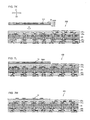
- FIG. 7A is a view to illustrate a step in a method for manufacturing a wiring board shown in FIG. 6 ;
- FIG. 7B is a view to illustrate a step in a method for manufacturing a wiring board shown in FIG. 6 ;
- FIG. 7C is a view to illustrate a step in a method for manufacturing a wiring board shown in FIG. 6 ;
- FIG. 7D is a view to illustrate a step in a method for manufacturing a wiring board shown in FIG. 6 ;
- FIG. 7E is a view to illustrate a step in a method for manufacturing a wiring board shown in FIG. 6 ;
- FIG. 7F is a view to illustrate a step in a method for manufacturing a wiring board shown in FIG. 6 ;
- FIG. 7G is a view to illustrate a step in a method for manufacturing a wiring board shown in FIG. 6 ;
- FIG. 7H is a view to illustrate a step in a method for manufacturing a wiring board shown in FIG. 6 ;
- FIG. 7I is a view to illustrate a step in a method for manufacturing a wiring board shown in FIG. 6 (the lower part is an enlarged cross-sectional view of main region (C) of the upper part);
- FIG. 7J is a view to illustrate a step in a method for manufacturing a wiring board shown in FIG. 6 ;
- FIG. 7K is a view to illustrate a step in a method for manufacturing a wiring board shown in FIG. 6 ;
- FIG. 7L is a view to illustrate a step in a method for manufacturing a wiring board shown in FIG. 6 ;
- FIG. 7M is a view to illustrate a step in a method for manufacturing a wiring board shown in FIG. 6 ;
- FIG. 7N is a view to illustrate a step in a method for manufacturing a wiring board shown in FIG. 6 ;
- FIG. 7P is a view to illustrate a step in a method for manufacturing a wiring board shown in FIG. 6 ;
- FIG. 8 is a cross-sectional view showing a main part of a wiring board according to a first modified example of the first embodiment
- FIG. 9A is a cross-sectional view showing a package substrate using a wiring board according to a second embodiment of the present invention (the lower part is an enlarged cross-sectional view of main region (A) of the upper part);
- FIG. 9B is a detailed cross-sectional view showing a package substrate using a wiring board according to the second embodiment.
- FIG. 10 is a plan view of FIG. 9A seen from direction Z 2 ;
- FIG. 11 is an enlarged cross-sectional view of a portion in FIGS. 9A and 9B , showing a main part of a wiring board in the second embodiment (the lower part is an enlarged cross-sectional view of main region (C) of the upper part);
- FIG. 12 is a flowchart showing the process for manufacturing a wiring board according to the second embodiment
- FIG. 13A is a view to illustrate a step in a method for manufacturing a wiring board shown in FIG. 12 ;
- FIG. 13B is a view to illustrate a step in a method for manufacturing a wiring board shown in FIG. 12 ;
- FIG. 13C is a view to illustrate a step in a method for manufacturing a wiring board shown in FIG. 12 ;
- FIG. 13D is a view to illustrate a step in a method for manufacturing a wiring board shown in FIG. 12 ;
- FIG. 14A is a cross-sectional view showing a main part of a wiring board according to a third embodiment (corresponding to the (E-E) cross section of FIG. 14B );
- FIG. 14B is a plan view showing a main part of a wiring board according to the third embodiment.
- FIG. 15 is a plan view showing a main part of a wiring board according to a fourth embodiment.
- FIG. 16 is a cross-sectional view showing a main part of a wiring board according to a fifth embodiment.
- Conductive layers are such layers that include one or multiple conductive patterns.
- Conductive layers may include conductive patterns that form electric circuits such as wiring (ground included), pads, lands and the like, or it may include a planar conductive pattern that does not form electric circuits.
- Opening portions include notches and slits in addition to holes and grooves.
- the conductor formed in a via hole is referred to as a via conductor, the conductor formed in a through hole as a through-hole conductor, and the conductor filled in an opening portion as a filled conductor.
- a land is a conductor formed on or on the periphery of a hole (via hole, through hole or the like), at least part of which is formed to be contiguous with the conductor inside the hole (via conductor, through-hole conductor or the like).
- Stacking means a via conductor is formed on the land of a via conductor formed in its lower layer. Namely, unless the bottom surface of a via conductor is positioned off the land of a via conductor formed in its lower layer, they are stacked. Multiple vias stacked as such are called stacked vias.
- Plating includes wet plating such as electrolytic plating and electroless plating as well as dry plating such as PVD (physical vapor deposition) and CVD (chemical vapor deposition).
- interlayer insulation film brand name; ABF-45SH, made by Ajinomoto
- ABF-45SH brand name; ABF-45SH, made by Ajinomoto
- the “width” of a hole or a column indicates the diameter if it is a circle, and 2 ⁇ (cross section/ ⁇ ) if it is other than a circle.
- measurements are not limited to such if they are clearly indicated otherwise.
- the average value of measurements is used (average value excluding abnormal values).
- values such as the maximum value be used instead of the average value.
- Wiring board 100 according to the present embodiment is a multilayer printed wiring board as shown in FIGS. 1A and 1B , for example.
- Wiring board 100 of the present embodiment is a buildup multilayer wiring board with a core substrate.
- it may be a double-sided rigid wiring board, flexible wiring board or flex-rigid wiring board.
- the measurements, number of layers and the like of conductive layers and insulation layers in wiring board 100 may be modified freely within a scope of the technological concept of the present invention.
- MPU micro-processing unit
- DRAM dynamic random access memory
- Wiring board 100 has core substrate 20 , interlayer insulation layers ( 25 a , 26 a ) (first insulation layers), interlayer insulation layer ( 39 a ) (second insulation layer), interlayer insulation layers ( 25 b , 26 b , 33 b , 39 b ), conductive layers ( 24 a , 29 a ), conductive layer ( 35 a ) (first conductive pattern), conductive layer ( 37 c ) (third conductive pattern), conductive layers ( 24 b , 29 b , 31 b , 35 b , 37 d ), via conductors ( 23 , 30 a , 36 a , 38 c , 30 b , 32 b , 36 b , 38 d ), and solder-resist layers ( 40 a , 40 b ) formed on the outermost layers.
- Core substrate 20 has first surface (F 1 ) (Z 1 side) and its opposing second surface (F 2 ) (Z 2 side), and via conductors 23 penetrate through core substrate 20 .
- Core substrate 20 , via conductors 23 and conductive layers ( 24 a , 24 b ) correspond to the core section.
- buildup section (B 1 ) is formed on the first-surface (F 1 ) side of core substrate 20
- buildup section (B 2 ) is formed on the second-surface (F 2 ) side of core substrate 20 .
- Buildup section (B 1 ) includes three pairs of interlayer insulation layers and conductive layers (interlayer insulation layers ( 25 a , 26 a , 39 a ) and conductive layers ( 24 a , 29 a , 35 a , 37 c )).
- Buildup section (B 2 ) includes four pairs of interlayer insulation layers and conductive layers (interlayer insulation layers ( 25 b , 26 b , 33 b , 39 b ) and conductive layers ( 24 b , 29 b , 31 b , 35 b , 37 d )).
- solder-resist layer ( 40 a ) is positioned on the uppermost surface layer on the first-surface (F 1 ) side of core substrate 20 .
- solder-resist layer ( 40 b ) is positioned on the uppermost surface layer on the second-surface (F 2 ) side of core substrate 20 .
- Penetrating holes 21 that penetrate through core substrate 20 is formed in core substrate 20 .
- Via conductors 23 are filled conductors, and are formed by filling penetrating holes 21 with conductors.
- Conductive layer ( 24 a ) formed on first surface (F 1 ) of core substrate 20 and conductive layer ( 24 b ) formed on second surface (F 2 ) of core substrate 20 are electrically connected to each other through via conductors 23 .
- Core substrate 20 is formed by impregnating core material with resin, for example.
- Core substrate 20 is formed by impregnating fiberglass cloth with epoxy resin, which is then thermally treated and shaped into a sheet, for example.
- any other material may be used for core substrate 20 .
- Via conductors 23 are shaped like an hourglass with diameters decreasing from first surface (F 1 ) and second surface (F 2 ) of core substrate 20 toward the center, for example.
- the planar shape of via conductors 23 (X-Y plane) is a perfect circle, for example. However, that is not the only option, and any other shape may be employed for via conductors 23 .
- via conductors ( 30 a , 36 a , 38 c , 30 b , 32 b , 36 b , 38 d ) are formed respectively.
- Those via conductors are each a filled conductor, and are formed by filling conductor in via holes that penetrate through their respective interlayer insulation layers.
- Via conductors ( 30 a , 36 a , 38 c , 30 b , 32 b , 36 b , 38 d ) are shaped in a tapering column (truncated cone) tapering with a diameter that decreases toward core substrate 20 , for example, and their planar shape (X-Y plane) is a perfect circle, for example. However, that is not the only option, and any other shape may be employed for via conductors ( 30 a ) and the like.
- Interlayer insulation layer ( 25 a ) (the lowermost interlayer insulation layer of buildup section (B 1 )), interlayer insulation layer ( 25 b ) (the lowermost interlayer insulation layer of buildup section (B 2 )), and their upper interlayer insulation layers ( 26 a , 39 a , 26 b , 33 b , 39 b ) are each made of interlayer insulation film (brand name ABF-45SH, made by Ajinomoto), for example.
- those interlayer insulation layers may also be formed using FR-4 material made by impregnating core material with resin, for example.
- FR-4 material is obtained by impregnating fiberglass cloth with epoxy resin, which is then thermally treated and shaped into a sheet.
- the material of each interlayer insulation layer is not limited specifically, and any other material may be used.
- Solder bumps ( 43 a ) are positioned on the uppermost layer of wiring board 100 . Solder bumps ( 43 a ) are electrically connected to MPU 50 and DRAM 51 through conductive pads ( 50 a , 51 a ).
- Wiring board 100 includes main wiring board 200 and wiring structure 10 incorporated in main wiring board 200 .
- Wiring structure 10 is designed not according to design rules for multilayer printed wiring boards, but according to design rules for semiconductor elements such as ICs and LSIs as described later in detail.
- wiring structure 10 is designed to have a finer L/S (line/space) ratio of line to space, which is an indicator of wiring density.
- a line means the width of a pattern
- space is the space between patterns, which is the distance between the centers of two pattern widths.
- wiring structure 10 is designed to have high-density wiring with an L/S ratio of line to space at 1 ⁇ m/1 ⁇ m or greater but 5 ⁇ m/5 ⁇ m or less, preferably 3 ⁇ m/3 ⁇ m or greater but 5 ⁇ m/5 ⁇ m or less. Such ratios are very fine compared with L/S ratios at approximately 10 ⁇ m/10 ⁇ m of regular multilayer printed wiring boards such as main wiring board 200 of the present embodiment.
- Main wiring board 200 includes signal transmission lines and power lines to supply power to terminals (Vdd) of semiconductors MPU 50 and DRAM 51 (see FIG. 2 ).
- Wiring structure 10 includes lowermost adhesive layer ( 120 c ), insulation layer 120 (fourth insulation layer) on adhesive layer ( 120 c ), and conductive patterns 111 (second conductive patterns) for signal transmission formed in insulation layer 120 .
- conductive patterns 111 are made up of first conductive film ( 111 a ) and second conductive film ( 111 b ). Any of polyimide, phenol resin or polybenzoxazole resin is used as the material for insulation layer 120 .
- conductive pads ( 36 c ) are formed on wiring structure 10 to be connected to conductive pads ( 50 a ) of MPU 50 and conductive pads ( 51 a ) of DRAM 51 (see FIG. 1B ) through conductive pads ( 38 a ).
- top surfaces of conductive patterns 111 of wiring structure 10 are set to be positioned on substantially the same plane as top surfaces of conductive layers ( 35 a ) of main wiring board 200 .
- the pattern width of conductive patterns 111 of wiring structure 10 is smaller than the pattern widths of conductive layers ( 37 c , 35 a , 29 a , 24 a , etc.) of main wiring board 200 .
- adhesives such as an epoxy-resin type, an acrylic-resin type and a silicone-resin type are used. Holes with fine diameters are formed in insulation layer 120 . Those holes are filled with conductor to form filled via conductors ( 120 a ).
- insulation layer 110 (third insulation layer) is placed between conductive patterns 111 and adhesive layer ( 120 c ).
- wiring structure 10 is triple-layered.
- the present embodiment is not limited to such, and it is an option for wiring structure 10 to be double-layered without including insulation layer 110 and to have conductive patterns 111 directly formed on adhesive layer ( 120 c ).
- the distance between conductive pads ( 38 e ) (first pads) connected to MPU 50 is smaller than the distance between conductive pads ( 38 f ) (second pads) connected to DRAM 51 .
- the distance between adjacent conductive patterns 111 is smaller than the distance between adjacent conductive layers ( 35 a ).
- Wiring structure 10 does not include power-supply lines and includes only signal transmission lines, and is used to transmit signals between MPU 50 and DRAM 51 .
- conductive patterns 111 are used for signal transmission between MPU 50 and DRAM 51 , but are not used for power supply to MPU 50 and DRAM 51 .
- Power terminals (Vdd) of MPU 50 and DRAM 51 are electrically connected to stacked vias 80 in main wiring board 200 (see FIG. 1A , FIG. 3 ) so that power is supplied from an outside DC power source.
- Ground terminals (Gnd) (see FIG. 3 ) of MPU 50 and DRAM 51 are connected to ground through other stacked vias in main wiring board 200 .
- wiring structure 10 is formed on interlayer insulation layer ( 39 a ) positioned as first layer from the top. However, if it is formed on interlayer insulation layer ( 26 a ) positioned as second layer from the top, for example, the effect of a small dent that may occur on the top surface of wiring board 100 is reduced by uppermost interlayer insulation layer ( 39 a ). As a result, solder bumps ( 43 a ) are formed to have a uniform height. Also, under such conditions, wiring structure 10 becomes tolerant to damage from stress, compared with when wiring structure 10 is formed on the uppermost layer.
- Via conductors ( 120 a ) are electrically connected to upper-layer conductive pads ( 36 c ).
- conductive pads ( 36 c ) are electrically connected to MPU 50 and DRAM 51 through upper-layer conductive pads ( 38 a ), nickel-plated layer ( 41 a ), gold-plated layer ( 42 a ), solder bumps ( 43 a ) and conductive pads ( 50 a , 51 a ).
- the diameter of via conductors ( 120 a ) is preferred to be 1 ⁇ m or greater but 10 ⁇ m or smaller, more preferably, 0.5 ⁇ m or greater but 5 ⁇ m or smaller.
- design freedom for wiring distribution of conductive patterns 111 increases in wiring structure 10 .
- using conductive patterns 111 formed only in single insulation layer 120 more wiring lines are distributed from either the right or left side of wiring structure 10 .
- conductive patterns 111 are formed only in one layer, the total number of wiring layers decreases in wiring structure 10 .
- via conductors ( 36 a , 38 c ) are formed respectively in via holes of interlayer insulation layers ( 26 a , 39 a ) by means of metal layers ( 305 a , 307 c ) made of metal foil such as copper foil, electroless copper-plated film and electrolytic copper-plated film.
- diameter (width) (D 2 ) on the top surface of via conductor ( 38 c ) is 62 ⁇ m, for example, and diameter (D 1 ) of solder bump ( 43 a ) is 46 ⁇ m, for example.
- thickness (t 1 ) of wiring structure 10 (excluding adhesive layer ( 120 c )) is 25 ⁇ m, for example, and thickness (t 2 ) of adhesive layer ( 120 c ) of wiring structure 10 is 10 ⁇ m, for example, thickness (t 3 ) of conductive layer ( 35 a ) is 15 ⁇ m, for example, and thickness (t 4 ) of solder-resist layer ( 40 a ) is 15 ⁇ m, for example.
- thickness (t 2 ) of adhesive layer ( 120 c ) of wiring structure 10 is approximately 10 ⁇ m, sufficient adhesive strength is achieved with main wiring board 200 , allowing a wide selection of the material for adhesive layer ( 120 c ).
- thickness (t 1 ) of wiring structure 10 and the thickness of interlayer insulation layer ( 39 a ) are the same, or not to be strictly the same as shown in the drawing.
- Diameter (D 3 ) of conductive pad ( 36 c ) on wiring structure 10 is 15 ⁇ m or greater but 25 ⁇ m or less.
- surfaces of conductive pad ( 38 a ) and conductive layer ( 37 c ) are coated with OSP (organic solder preservative), NiPdAu, NiAu, Sn or the like in the present embodiment. Accordingly, oxidation is prevented on the surfaces of conductive pad ( 38 a ) and conductive layer ( 37 c ) when exposed to the outside.
- OSP organic solder preservative
- solder bumps ( 43 a ) are positioned on via conductors ( 38 c ) in opening portions (SRO) of solder-resist layers ( 40 a , 40 b ).
- Nickel-plated layer ( 41 a ) and gold-plated layer ( 42 a ) are formed between solder bump ( 43 a ) and via conductor ( 38 c ) (conductive layer ( 37 c )).
- diameter (Da) of opening portions 44 in solder-resist layers ( 40 a , 40 b ) is approximately 10% larger than diameter (Db) of the opening portions of uppermost via conductors ( 38 c ).
- diameter (Da) of opening portions in solder-resist layers ( 40 a , 40 b ) is greater than diameter (Db)
- Db diameter of via conductors ( 120 a )
- no through hole is formed in wiring board 100 to penetrate through all the layers of main wiring board 200 .
- that is not the only option By forming through holes penetrating through all the layers of main wiring board 200 and by electrically connecting conductive layers on the surface layers to each other, such through holes are used for signal transmission and power supply to a semiconductor element on wiring board 100 .
- via conductors ( 30 a , 32 a , 36 a , 38 c , 30 b , 32 b , 36 b , 38 d ) formed in core substrate 20 have substantially the same size as each other. By so setting, it is easier to set uniform electrical characteristics and manufacturing conditions.
- main wiring board 200 incorporates wiring structure 10 , which has higher wiring density than main wiring board 200 and is used for signal transmission between semiconductor elements.
- design freedom is enhanced for wiring board 100 (a multilayer printed wiring board). For example, concentration of all the power and signal wiring lines onto a specific region of a wiring board can be avoided. Also to be avoided are structures where only resin, but no conductor, exists in the region surrounding an electronic component.
- the process for manufacturing wiring board 100 is made up of the process for manufacturing wiring structure 10 and the process for manufacturing main wiring board 200 , which includes steps for mounting wiring structure 10 in main wiring board 200 (multilayer printed board).
- Wiring structure 10 is manufactured by the process shown in FIG. 4 , for example.
- Support sheet 1001 is prepared as shown in FIG. 5A in step (S 11 ) of FIG. 4 .
- Support sheet 1001 is glass with a flat surface, for example.
- Adhesive layer 1002 is formed on support sheet 1001 .
- laminated section 101 is formed on support sheet 1001 with adhesive layer 1002 in between.
- Laminated section 101 is formed by alternately laminating resin insulation layers and conductive patterns (conductive layers).
- insulation layer 110 (resin insulation layer) made of resin, for example, is positioned on adhesive layer 1002 as shown in FIG. 5B . Insulation layer 110 and adhesive layer 1002 are adhered through thermal treatment, for example.
- conductive patterns 111 are formed on insulation layer 110 using a semi-additive (SAP) method, for example.
- First conductive film ( 111 a ) (see FIG. 3 ) of conductive patterns 111 is triple-layered with a TiN layer (lower layer), a Ti layer (middle layer) and a Cu layer (upper layer). Since those metal layers are each formed by sputtering, for example, excellent adhesiveness is secured between fine conductive patterns 111 and base material (insulation layer 110 ).
- second conductive film ( 111 b ) of conductive patterns 111 is made of electroless copper-plated film on the Cu layer and electrolytic plated film on the electroless copper-plated film.
- Conductive patterns 111 are formed to be high density with an L/S (line/space) ratio of line to space at 1 ⁇ m/1 ⁇ m or greater but 5 ⁇ m/5 ⁇ m or less, preferably 3 ⁇ m/3 ⁇ m or greater but 5 ⁇ m/5 ⁇ m or less.
- a line means a pattern width
- space is the space between patterns, which is the distance between the centers of two pattern widths.
- wiring is set to be high density using the same design rules as those for forming semiconductor elements such as ICs (integrated circuits) or LSIs (large scale integrated circuits).
- insulation layer 120 is formed on insulation layer 110 by lamination, for example. Insulation layer 120 is formed to cover conductive patterns 111 .
- holes via holes are formed in insulation layer 120 . Holes are formed to reach and expose portions of conductive patterns 111 .
- the diameter of the holes is set to be a fine size of 1 ⁇ m or greater but 10 ⁇ m or smaller, more preferably 0.5 ⁇ m or greater but 5 ⁇ m or smaller. Then, desmearing and soft etching are conducted as needed.
- laminated section 101 which is made up of insulation layers ( 110 , 120 ) and conductive patterns 111 , is formed on support sheet 1001 .
- Via conductors ( 120 a ) are formed in insulation layer 120 of laminated section 101 .
- Conductive pads ( 36 c ) are formed on insulation layer 120 to be connected to via conductors ( 120 a ).
- step (S 13 ) of FIG. 4 another support sheet 1003 is prepared, as shown in FIG. 5F .
- support sheet 1003 is made of glass with a flat surface, for example.
- support sheet 1003 is laminated on laminated section 101 with adhesive layer ( 120 b ) in between.
- step (S 14 ) of FIG. 4 support sheet 1001 is removed. Specifically, for example, after adhesive layer 1002 is softened by irradiating a laser, by sliding support sheet 1001 in direction X (or direction Y), as shown in FIG. 5G , support sheet 1001 is removed from a second main surface of laminated section 101 . If adhesive layer 1002 remains on the second surface of laminated section 101 after support sheet 1001 has been removed from laminated section 101 , such adhesive layer 1002 is removed by cleansing. In doing so, laminated section 101 is formed on support sheet 1003 as shown in FIG. 5H . Support sheet 1001 may be used again by cleaning it, for example.
- adhesive layer ( 120 c ) is formed on laminated section 101 using an adhesive such as an epoxy-resin type, an acrylic-resin type, a silicone-resin type or the like. Specifically, adhesive layer ( 120 c ) is formed on laminated section 101 by laminating an adhesive using a laminator to make uniform thickness.
- step (S 16 ) of FIG. 4 using a dicing saw, for example, individual units are obtained by cutting along predetermined dicing lines as shown in FIG. 5I . Accordingly, multiple wiring structures 10 are obtained.
- laminated section 101 is formed on support sheet 1003 with adhesive layer ( 120 b ) placed in between, and adhesive layer ( 120 c ) is further formed on laminated section 101 .
- wiring board 100 is made with high quality having flat surfaces and suppressed warping.
- Main wiring board 200 is manufactured, while wiring structure 10 is mounted in main wiring board 200 to obtain wiring board 100 of the present embodiment.
- Wiring board 100 is manufactured by a process shown in FIG. 6 , for example.
- core substrate 20 made by impregnating reinforcing material with resin is prepared as shown in FIG. 7A .
- Copper foil ( 20 a ) is laminated on first surface (F) and second surface (S) of core substrate 20 .
- the thickness of core substrate 20 is 0.4 mm or greater but 0.7 mm or less, for example.
- reinforcing material glass cloth, aramid fabric, glass fabric or the like is used, for example.
- resin epoxy resin, BT (bismaleimide triazine) resin or the like is used, for example.
- hydroxide particles are contained in resin.
- hydroxide metal hydroxides such as aluminum hydroxide, magnesium hydroxide, calcium hydroxide, barium hydroxide and the like are listed. Since hydroxide decomposes on heating to produce water, it is thought that hydroxide robs heat from the material to form a core substrate. Namely, when the core substrate contains hydroxide, it is thought that laser processing results improve.
- a solution containing NaOH (10 g/L), NaClO 2 (40 g/L) and Na 3 PO 4 (6 g/L) is applied on the surface of copper foil ( 20 a ) to conduct a black-oxide treatment by blackening bath (oxidation bath).
- a CO 2 laser is used to irradiate a laser from the first-surface (F) (upper-surface) side and the second-surface (S) (lower-surface) side of core substrate 20 to form penetrating holes 21 that penetrate through core substrate 20 , as shown in FIG. 7B .
- a CO 2 laser is used to irradiate a laser from the first-surface (F) (upper-surface) side and the second-surface (S) (lower-surface) side of core substrate 20 to form penetrating holes 21 that penetrate through core substrate 20 , as shown in FIG. 7B .
- holes bored from the first-surface (F) side and the second-surface (S) side are joined together to form penetrating hole 21 .
- Desmearing is conducted on core substrate 20 by immersing it in a solution containing permanganic acid at a predetermined concentration. At that time, core substrate 20 is preferred to be treated so that the percentage of its weight loss is 1.0 wt. % or lower, preferably 0.5 wt. % or lower. Since core substrate 20 is formed by impregnating reinforcing material such as glass cloth with resin, glass cloth may protrude into penetrating holes when resin is dissolved during the desmearing treatment. However, if the percentage of weight loss of core substrate 20 is in such a range, protrusion of glass cloth is suppressed, thus preventing voids when plating is filled in penetrating holes. Then, a palladium catalyst is attached on the surfaces of core substrate 20 .
- Core substrate 20 is immersed in an electroless plating solution to form electroless plated film 22 on first surface (F) and second surface (S) of core substrate 20 and on the inner walls of penetrating holes 21 as shown in FIG. 7C .
- electroless plated film 22 copper, nickel and the like are listed.
- Electrolytic plated film is formed on electroless plated film 22 using electroless plated film 22 as a seed layer. Accordingly, penetrating holes 21 are filled with electrolytic plated film to form via conductors 23 .
- Etching resist with a predetermined pattern is formed on electrolytic plated film on substrate surfaces, and electroless plated film 22 , electrolytic plated film and copper foil are removed from where no etching resist is formed, as shown in FIG. 7D . Then, etching resist is removed. Accordingly, conductive layers ( 24 a ) are formed on first surface (F) of core substrate 20 , and conductive layers ( 24 b ) are formed on second surface (S) of core substrate 20 . Conductive layers ( 24 a ) and conductive layers ( 24 b ) are electrically connected to each other by via conductors 23 made of electrolytic plated film in penetrating holes 21 .
- interlayer insulation film brand name ABF-45SH, made by Ajinomoto, for example, is laminated on both surfaces (F, S) of core substrate 20 to form interlayer insulation layers ( 25 a , 25 b ) as shown in FIG. 7E .
- via-hole opening portions ( 26 c , 26 d ) are formed respectively in interlayer insulation layers ( 25 a , 25 b ) as shown in FIG. 7F .
- the substrate is immersed in an oxidant such as permanganate to conduct a desmearing treatment.
- a palladium catalyst or the like is attached to surfaces of interlayer insulation layers ( 25 a , 25 b ) and the substrate is immersed in an electroless plating solution to form electroless plated films ( 27 a , 27 b ) as shown in FIG. 7G .
- plating resist (not shown) is formed on electroless plated films ( 27 a , 27 b ).
- Electrolytic plated films ( 28 a , 28 b ) are formed on portions of electroless plated films ( 27 a , 27 b ) exposed from the plating resist. After that, plating resist is removed using a solution containing monoethanolamine.
- conductive layers ( 29 a , 29 b ) and via conductors ( 30 a , 30 b ) are formed as shown in FIG. 7H .
- Sn plating is performed on surfaces of conductive layers ( 29 a , 29 b ) to form SnCu layers.
- a silane coupling agent is applied on the SnCu layers.
- step (S 24 ) of FIG. 6 the above-described steps are repeated as shown in FIG. 7I .
- interlayer insulation layers ( 26 a , 26 b ) are laminated on interlayer insulation layers ( 25 a , 25 b ), and then conductive layers ( 35 a , 31 b ) and via conductors ( 36 a , 32 b ) are formed on interlayer insulation layers ( 26 a , 26 b ) as shown in FIG. 7J .
- step (S 25 ) of FIG. 6 wiring structure 10 is mounted on a predetermined region on interlayer insulation layer ( 26 a ) with adhesive layer ( 120 c ) placed in between as shown in FIG. 7K , thus achieving the state shown in FIG. 7L .
- Support sheet 1003 is removed as shown in FIG. 7M , and then adhesive layer ( 120 b ) is removed.
- interlayer insulation layer ( 33 b ) is laminated on interlayer insulation layer ( 26 b ), and interlayer insulation layer ( 39 a , 39 b ) are laminated respectively on wiring structure 10 and interlayer insulation layer ( 33 b ) as shown in FIG. 7N .
- the above-described steps are further repeated.
- interlayer insulation layer ( 39 a ) and interlayer insulation layers ( 33 b , 39 b ) are laminated on interlayer insulation layers ( 26 a , 26 b ) respectively, and conductive layers ( 37 c ) (third conductive patterns) and via conductors ( 38 c ) are formed on interlayer insulation layer ( 39 a ).
- conductive layers ( 35 b , 37 d ) and via conductors ( 36 b , 38 d ) are formed on interlayer insulation layers ( 33 b , 39 b ).
- solder-resist layers ( 40 a , 40 b ) with opening portions 44 are formed by photolithography on both surfaces of the substrate. Upper surfaces of conductive layers ( 37 c , 37 d ) and via conductors ( 38 c , 38 d ) exposed from opening portions 44 work as solder pads (mounting pads).
- step (S 27 ) of FIG. 6 nickel-plated layers ( 41 a , 41 b ) are formed on solder pads, and gold-plated layers ( 42 a , 42 b ) are further formed on nickel-plated layers ( 41 a , 41 b ) as shown in FIG. 7P .
- nickel-gold layers nickel-palladium-gold layers may also be formed.
- thin film made of OSP (organic solder preservative), NiPdAu, NiAu, Sn or the like is formed to cover conductive pads ( 38 a ) and mounting pads for conductive layers ( 37 c ) exposed to the outside from opening portions 44 on the upper surface of wiring board 100 .
- solder balls are loaded in opening portions 44 and a reflow is conducted to form solder bumps ( 43 a ) on the first-surface (upper-surface) side and solder bumps ( 43 b ) on the second-surface (lower-surface) side. Accordingly, wiring board 100 of the present embodiment is completed as a multilayer printed wiring board.
- the method for manufacturing wiring board 100 of the present embodiment is not limited to the above embodiment, and may be modified within a scope that does not deviate from the technological concept of the present invention. Modified examples of the present embodiment are described below.
- wiring structure 10 is formed in the interlayer insulation layer positioned as first layer from the top. However, that is not the only option, and wiring structure 10 may be formed on interlayer insulation layer ( 39 a ) as shown in FIG. 8 . In such a case, wiring structure 10 is covered with solder-resist layer ( 40 a ). Also, conductive pads ( 36 c ) work as mounting pads to mount a semiconductor chip. Except for such modifications, the rest of the structure and measurements of each element are the same as in the above embodiment.
- wiring structure 10 is formed on interlayer insulation layer ( 39 a ) positioned as first layer from the top and is covered by solder-resist layer ( 40 a ).
- via conductor ( 120 a ) of wiring structure 10 is connected to solder bump ( 43 a ) through conductive pad ( 36 c ) as shown in FIG. 8 .
- via conductor ( 120 a ) of wiring structure 10 may also be connected to solder bump ( 43 a ) through under-bump metal (UBM) substituted for conductive pad ( 36 c ).
- UBM under-bump metal
- the rest of the structure and measurements of each element are the same as in the above Modified Example 1.
- the process for manufacturing wiring board 100 it is the same as the above embodiment, except that via conductor ( 120 a ) of wiring structure 10 is connected to solder bump ( 43 a ) through under-bump metal (UBM).
- wiring structure 10 was formed in one region on interlayer insulation layer ( 26 a ) as shown in FIGS. 1A , 1 B and 2 .
- wiring structure 10 may also be formed in the entire region of interlayer insulation layer ( 26 a ) as shown in FIGS. 9A , 9 B and 10 .
- interlayer insulation layer ( 26 a ) of main wiring board 200 of the first embodiment is entirely covered by wiring structure 10 .
- the process for manufacturing wiring board 100 is made up of the process for manufacturing wiring structure 10 and the process for manufacturing main wiring board 200 , which includes a step for mounting wiring structure 10 .
- Wiring structure 10 is manufactured by a process shown in FIG. 4 , the same as in the first embodiment, for example. However, step (S 16 ) of FIG. 4 for obtaining individual units is not conducted. Instead, wiring structure 10 is mounted in main wiring board 200 in such a state as shown in FIG. 5H , for example. Also, support sheet 1003 is not used in the present embodiment.
- Main wiring board 200 is manufactured, while wiring structure 10 is mounted in main wiring board 200 to manufacture wiring board 100 of the present embodiment.
- Wiring board 100 is manufactured by a process shown in FIG. 12 , for example.
- wiring board 100 is manufactured following the steps up to step (S 24 ) of the processing flow in the first embodiment shown in FIG. 6 (up to step (S 34 ) of FIG. 12 in the present embodiment). Namely, since wiring board 100 of the present embodiment is manufactured following the same steps as in FIGS. 7A ⁇ 7J of the first embodiment, their descriptions are omitted here.
- step (S 36 ) of FIG. 12 interlayer insulation layers ( 39 a , 39 b ) are laminated on wiring structure 10 and interlayer insulation layer ( 33 b ) as shown in FIG. 13C . Then, the above steps are repeated. Accordingly, from the first-surface (F) side of core substrate 20 , wiring structure 10 is laminated on interlayer insulation layer ( 26 a ). After that, solder-resist layers ( 40 a , 40 b ) with opening portions 44 are formed on both surfaces of the substrate. Here, upper surfaces of conductive layers ( 37 c , 37 d ) and via conductors ( 38 c , 38 d ) exposed from opening portions 44 work as solder pads.
- step (S 37 ) of FIG. 12 nickel-plated layers ( 41 a , 41 b ) are formed on solder pads, and gold-plated layers ( 42 a , 42 b ) are further formed on nickel-plated layers ( 41 a , 41 b ) as shown in FIG. 13D .
- nickel-gold layers nickel-palladium-gold layers may also be formed.
- solder balls are loaded in opening portions 44 and a reflow is conducted to form solder bumps ( 43 a ) on the first-surface (upper-surface) side and solder bumps ( 43 b ) on the second-surface (lower-surface) side. Accordingly, wiring board 100 is completed as a multilayer printed wiring board.
- the number of conductive layers formed on the first-surface (F 1 ) side of core substrate 20 and the number of conductive layers formed on the second-surface (F 2 ) side of core substrate 20 are three and four respectively.
- the number of layers (number of conductive layers) of a wiring board, to which the above structures are applied is modified freely within a scope for practical use.
- wiring board 102 of the present embodiment main wiring board 202 , wiring structure 10 in the above first embodiment, and electrical wiring 55 formed on interlayer insulation layer ( 39 a ) are used as shown in FIG. 14A .
- Solder bumps are not formed directly on wiring structure 10 , and wiring structure 10 is electrically connected to an outside semiconductor chip (not shown) using solder bumps ( 43 a ) formed on electrical wiring 55 .
- the rest of the structure and functions are the same as those of wiring board 100 in the first embodiment and its modified examples. Thus, except for the following description, other descriptions are omitted here by applying the same reference numbers for the corresponding portions.
- interlayer insulation layers 25 e , 25 a , 26 a , 33 a , 39 a ) are laminated in that order on core substrate 20 , and the uppermost layer is covered with solder-resist layer ( 40 a ).
- Wiring structure 10 is built into interlayer insulation layer ( 39 a ), which is positioned directly under solder-resist layer ( 40 a ).
- conductive pad ( 55 a ) in the center of a memory (DRAM) and conductive pad ( 55 b ) on wiring structure 10 are electrically connected through electrical wiring 55 , as shown in FIG. 14B .
- two wiring structures 10 are formed in wiring board 103 of the present embodiment. Except that MPU 50 and two DRAMs ( 51 c , 51 d ) are connected by two wiring structures 10 , the rest is the same as with wiring board 100 according to the first embodiment and modified examples. Thus, a detailed description of the corresponding portions is omitted here by applying the same reference numbers.
- wiring structure 10 corresponding to characteristics of DRAMs ( 51 c , 51 d ) (wiring pitch, wiring width, etc.) can be used exclusively, for example, so that accuracy in electrical connections improves. As a result, maximum performance of DRAMs ( 51 c , 51 d ) connected to MPU 50 is achieved.
- wiring structure 10 used in the above first through fourth embodiments and modified examples is built into insulation layer 46 formed as the uppermost layer of wiring board 104 , while electrically connected to IC chip 61 provided on insulation layer 46 .
- wiring structure 10 is used as an electronic component exclusively for IC chip 61 .
- interlayer insulation layer 47 and insulation layer 46 are formed in that order on core substrate 20 .
- the space between IC chip 61 and insulation layer 46 is sealed with underfill resin 70 .
- wiring structure 10 is manufactured by a process of its own, separate from wiring board 104 , and is built into wiring board 104 . Therefore, wiring structure 10 is designed and manufactured exclusively corresponding to the characteristics of IC chip 61 (wiring pitch, wiring width, etc.), and is built into wiring board 104 to be electrically connected to IC chip 61 . As a result, defects in wiring structure 10 are reduced, and the production yield of wiring board 104 is improved accordingly.
- a process for manufacturing a wiring board related to the present invention is not limited to the order and contents described in each of the embodiments and modified examples. Such order and contents may be freely modified within a scope that does not deviate from the gist of the present invention. Also, some step may be omitted depending on usage or the like.
- a wiring board is characterized by the following: a first insulation layer; a first conductive pattern formed on the first insulation layer; a second insulation layer formed on the first insulation layer and on the first conductive pattern; a wiring structure positioned on the first insulation layer and having a third insulation layer and a second conductive pattern on the third insulation layer; a third conductive pattern formed on the second insulation layer; and a via conductor formed in the second insulation layer and connecting the first conductive pattern and the third conductive pattern.
- the pattern width of the second conductive pattern may be smaller than the pattern width of the first conductive pattern.
- the distance between the adjacent second conductive patterns may be smaller than the distance between the adjacent first conductive patterns.
- the upper surface of the first conductive pattern and the upper surface of the second conductive pattern may be positioned on the same plane.
- the wiring structure may further include a fourth insulation layer formed on the third insulation layer and covering the second conductive pattern, a via conductor penetrating through the fourth insulation layer, and a conductive pad connected to the via conductor.
- An adhesive layer may be formed between the first insulation layer and the wiring structure.
- Conductive pads may be formed on the fourth insulation layer to be connected to mounting pads for mounting a first semiconductor element and a second semiconductor element.
- the mounting pads may include first pads connected to the first semiconductor element and second pads connected to the second semiconductor element, and the distance between the first pads is preferred to be smaller than the distance between the second pads.
- the second conductive pattern may be a signal line connecting the first semiconductor element and the second semiconductor element.
- the L/S (line/space) of the second conductive pattern may be 1 ⁇ m/1 ⁇ m or greater but 5 ⁇ m/5 ⁇ m or less.
- the wiring structure may cover the first insulation layer completely.
- the second conductive pattern of the wiring structure may be connected to the third conductive pattern by electrical wiring formed above the wiring structure, and that the second conductive pattern be electrically connected to an outside semiconductor chip through the electrical wiring and the third conductive pattern.
- the wiring board may have at least two of the wiring structures, and that a semiconductor chip on the wiring board be electrically connected to different semiconductor chips through separate wiring structures.
- the wiring structure may be built into an uppermost insulation layer of the wiring board, and be electrically connected to a semiconductor chip provided on the insulation layer.
- a method for manufacturing a wiring board is characterized by the following: forming a first conductive pattern on a first insulation layer; forming a second insulation layer on the first insulation layer and on the first conductive pattern; forming a via conductor in the second insulation layer; forming a third conductive pattern on the second insulation layer; on the first insulation layer, positioning a wiring structure having a third insulation layer and a second conductive pattern on the third insulation layer; and connecting the third conductive pattern and the first conductive pattern by a via conductor in the second insulation layer.
- Wiring boards according to the embodiments of the present invention are suitable as package substrates for mounting multiple semiconductor elements (dies). Also, manufacturing methods according to the embodiments of the present invention are suitable for manufacturing such package substrates.
Priority Applications (1)
| Application Number | Priority Date | Filing Date | Title |
|---|---|---|---|
| US14/723,520 US20150264817A1 (en) | 2012-03-30 | 2015-05-28 | Wiring board and method for manufacturing the same |
Applications Claiming Priority (2)
| Application Number | Priority Date | Filing Date | Title |
|---|---|---|---|
| JP2012083288A JP2013214578A (ja) | 2012-03-30 | 2012-03-30 | 配線板及びその製造方法 |
| JP2012-083288 | 2012-03-30 |
Related Child Applications (1)
| Application Number | Title | Priority Date | Filing Date |
|---|---|---|---|
| US14/723,520 Division US20150264817A1 (en) | 2012-03-30 | 2015-05-28 | Wiring board and method for manufacturing the same |
Publications (2)
| Publication Number | Publication Date |
|---|---|
| US20130258625A1 US20130258625A1 (en) | 2013-10-03 |
| US9066435B2 true US9066435B2 (en) | 2015-06-23 |
Family
ID=49234764
Family Applications (2)
| Application Number | Title | Priority Date | Filing Date |
|---|---|---|---|
| US13/853,227 Active 2033-05-29 US9066435B2 (en) | 2012-03-30 | 2013-03-29 | Wiring board and method for manufacturing the same |
| US14/723,520 Abandoned US20150264817A1 (en) | 2012-03-30 | 2015-05-28 | Wiring board and method for manufacturing the same |
Family Applications After (1)
| Application Number | Title | Priority Date | Filing Date |
|---|---|---|---|
| US14/723,520 Abandoned US20150264817A1 (en) | 2012-03-30 | 2015-05-28 | Wiring board and method for manufacturing the same |
Country Status (3)
| Country | Link |
|---|---|
| US (2) | US9066435B2 (ja) |
| JP (1) | JP2013214578A (ja) |
| CN (1) | CN103369816B (ja) |
Cited By (3)
| Publication number | Priority date | Publication date | Assignee | Title |
|---|---|---|---|---|
| US10438885B1 (en) | 2018-06-21 | 2019-10-08 | Advanced Semiconductor Engineering, Inc. | Semiconductor device package and method of manufacturing the same |
| US20200075540A1 (en) * | 2018-08-30 | 2020-03-05 | Advanced Semiconductor Engineering, Inc. | Substrate panel structure and manufacturing process |
| US11470727B2 (en) * | 2016-10-24 | 2022-10-11 | Jaguar Land Rover Limited | Apparatus and method relating to electrochemical migration |
Families Citing this family (23)
| Publication number | Priority date | Publication date | Assignee | Title |
|---|---|---|---|---|
| US9016552B2 (en) * | 2013-03-15 | 2015-04-28 | Sanmina Corporation | Method for forming interposers and stacked memory devices |
| JP2014236187A (ja) | 2013-06-05 | 2014-12-15 | イビデン株式会社 | 配線板及びその製造方法 |
| JP2014236188A (ja) | 2013-06-05 | 2014-12-15 | イビデン株式会社 | 配線板及びその製造方法 |
| JP2015159167A (ja) * | 2014-02-24 | 2015-09-03 | イビデン株式会社 | プリント配線板及びプリント配線板の製造方法 |
| JP2016029681A (ja) | 2014-07-25 | 2016-03-03 | イビデン株式会社 | 多層配線板及びその製造方法 |
| JP6358887B2 (ja) * | 2014-07-31 | 2018-07-18 | 新光電気工業株式会社 | 支持体、配線基板及びその製造方法、半導体パッケージの製造方法 |
| JP2016051847A (ja) * | 2014-09-01 | 2016-04-11 | イビデン株式会社 | プリント配線板、その製造方法及び半導体装置 |
| JP2016066745A (ja) * | 2014-09-25 | 2016-04-28 | イビデン株式会社 | プリント配線基板およびこれを備えた半導体装置 |
| JP6473595B2 (ja) | 2014-10-10 | 2019-02-20 | イビデン株式会社 | 多層配線板及びその製造方法 |
| US20160141234A1 (en) * | 2014-11-17 | 2016-05-19 | Qualcomm Incorporated | Integrated device package comprising silicon bridge in photo imageable layer |
| JP2016100599A (ja) * | 2014-11-17 | 2016-05-30 | サムソン エレクトロ−メカニックス カンパニーリミテッド. | プリント回路基板、その製造方法、及び電子部品モジュール |
| KR102207272B1 (ko) * | 2015-01-07 | 2021-01-25 | 삼성전기주식회사 | 인쇄회로기판, 그 제조방법, 및 전자부품 모듈 |
| KR101966328B1 (ko) * | 2016-03-29 | 2019-04-05 | 삼성전기주식회사 | 인쇄회로기판 및 그 제조방법 |
| KR102473408B1 (ko) * | 2016-03-29 | 2022-12-02 | 삼성전기주식회사 | 인쇄회로기판 및 그 제조방법 |
| US11128029B2 (en) * | 2016-09-26 | 2021-09-21 | Intel Corporation | Die with embedded communication cavity |
| KR102604148B1 (ko) * | 2016-10-14 | 2023-11-20 | 삼성전기주식회사 | 인쇄회로기판 및 그 제조방법 |
| US10418314B2 (en) * | 2017-11-01 | 2019-09-17 | Advanced Semiconductor Engineering, Inc. | External connection pad for semiconductor device package |
| KR102055595B1 (ko) * | 2017-12-15 | 2019-12-16 | 삼성전자주식회사 | 반도체 패키지 |
| JP2019134123A (ja) * | 2018-02-02 | 2019-08-08 | 株式会社フジクラ | 配線基板 |
| KR102542573B1 (ko) * | 2018-09-13 | 2023-06-13 | 삼성전자주식회사 | 재배선 기판, 이의 제조 방법, 및 이를 포함하는 반도체 패키지 |
| KR102601582B1 (ko) * | 2018-12-11 | 2023-11-14 | 삼성전자주식회사 | 반도체 패키지 및 그 제조방법 |
| JP7102481B2 (ja) * | 2020-10-09 | 2022-07-19 | Nissha株式会社 | 射出成形品及びその製造方法 |
| WO2023209986A1 (ja) * | 2022-04-28 | 2023-11-02 | 株式会社レゾナック | 薄型配線部材の製造方法、薄型配線部材、及び、配線基板の製造方法 |
Citations (8)
| Publication number | Priority date | Publication date | Assignee | Title |
|---|---|---|---|---|
| WO2007129545A1 (ja) | 2006-05-02 | 2007-11-15 | Ibiden Co., Ltd. | 耐熱性基板内蔵回路配線板 |
| US20090072384A1 (en) * | 2007-09-14 | 2009-03-19 | Phoenix Precision Technology Corporation | Packaging substrate having heat-dissipating structure |
| US20090129039A1 (en) * | 2005-06-15 | 2009-05-21 | Ibiden Co., Ltd. | Multilayer printed wiring board |
| US20090173522A1 (en) * | 2007-12-28 | 2009-07-09 | Ibiden Co., Ltd | Interposer and method for manufacturing interposer |
| US20110053318A1 (en) * | 2009-09-02 | 2011-03-03 | Unimicron Technology Corporation | Fabrication method of package structure |
| US20120008295A1 (en) | 2010-07-09 | 2012-01-12 | Ibiden Co., Ltd. | Wiring board and method for manufacturing the same |
| US20120006592A1 (en) | 2010-07-09 | 2012-01-12 | Ibiden Co., Ltd | Wiring board and method for manufacturing the same |
| US20120151632A1 (en) * | 2009-06-10 | 2012-06-14 | Novozymes A/S | Phospholipases and methods of using same |
Family Cites Families (10)
| Publication number | Priority date | Publication date | Assignee | Title |
|---|---|---|---|---|
| JP3724061B2 (ja) * | 1996-06-05 | 2005-12-07 | 富士電機機器制御株式会社 | 金属基板及びその製造方法 |
| JP2003298232A (ja) * | 2002-04-02 | 2003-10-17 | Sony Corp | 多層配線基板の製造方法および多層配線基板 |
| JP2009129933A (ja) * | 2007-11-19 | 2009-06-11 | Fujikura Ltd | 多層プリント配線板及び多層プリント配線板の製造方法 |
| JPWO2010038489A1 (ja) * | 2008-09-30 | 2012-03-01 | イビデン株式会社 | 電子部品内蔵配線板及びその製造方法 |
| TWI388247B (zh) * | 2009-09-16 | 2013-03-01 | Unimicron Technology Corp | 線路板結構 |
| US8334463B2 (en) * | 2009-10-30 | 2012-12-18 | Ibiden Co., Ltd. | Wiring board and method for manufacturing the same |
| JP2011159855A (ja) * | 2010-02-02 | 2011-08-18 | Panasonic Corp | 局所多層回路基板、および局所多層回路基板の製造方法 |
| US8654538B2 (en) * | 2010-03-30 | 2014-02-18 | Ibiden Co., Ltd. | Wiring board and method for manufacturing the same |
| WO2011155162A1 (ja) * | 2010-06-08 | 2011-12-15 | パナソニック株式会社 | 多層配線基板および多層配線基板の製造方法 |
| JP2012033879A (ja) * | 2010-06-30 | 2012-02-16 | Panasonic Corp | 部品内蔵基板及びその製造方法 |
-
2012
- 2012-03-30 JP JP2012083288A patent/JP2013214578A/ja active Pending
-
2013
- 2013-03-29 CN CN201310109960.7A patent/CN103369816B/zh active Active
- 2013-03-29 US US13/853,227 patent/US9066435B2/en active Active
-
2015
- 2015-05-28 US US14/723,520 patent/US20150264817A1/en not_active Abandoned
Patent Citations (8)
| Publication number | Priority date | Publication date | Assignee | Title |
|---|---|---|---|---|
| US20090129039A1 (en) * | 2005-06-15 | 2009-05-21 | Ibiden Co., Ltd. | Multilayer printed wiring board |
| WO2007129545A1 (ja) | 2006-05-02 | 2007-11-15 | Ibiden Co., Ltd. | 耐熱性基板内蔵回路配線板 |
| US20090072384A1 (en) * | 2007-09-14 | 2009-03-19 | Phoenix Precision Technology Corporation | Packaging substrate having heat-dissipating structure |
| US20090173522A1 (en) * | 2007-12-28 | 2009-07-09 | Ibiden Co., Ltd | Interposer and method for manufacturing interposer |
| US20120151632A1 (en) * | 2009-06-10 | 2012-06-14 | Novozymes A/S | Phospholipases and methods of using same |
| US20110053318A1 (en) * | 2009-09-02 | 2011-03-03 | Unimicron Technology Corporation | Fabrication method of package structure |
| US20120008295A1 (en) | 2010-07-09 | 2012-01-12 | Ibiden Co., Ltd. | Wiring board and method for manufacturing the same |
| US20120006592A1 (en) | 2010-07-09 | 2012-01-12 | Ibiden Co., Ltd | Wiring board and method for manufacturing the same |
Non-Patent Citations (1)
| Title |
|---|
| U.S. Appl. No. 13/853,338, filed Mar. 29, 2013, Terui, et al. |
Cited By (4)
| Publication number | Priority date | Publication date | Assignee | Title |
|---|---|---|---|---|
| US11470727B2 (en) * | 2016-10-24 | 2022-10-11 | Jaguar Land Rover Limited | Apparatus and method relating to electrochemical migration |
| US10438885B1 (en) | 2018-06-21 | 2019-10-08 | Advanced Semiconductor Engineering, Inc. | Semiconductor device package and method of manufacturing the same |
| US20200075540A1 (en) * | 2018-08-30 | 2020-03-05 | Advanced Semiconductor Engineering, Inc. | Substrate panel structure and manufacturing process |
| US10818636B2 (en) * | 2018-08-30 | 2020-10-27 | Advanced Semiconductor Engineering, Inc. | Substrate panel structure and manufacturing process |
Also Published As
| Publication number | Publication date |
|---|---|
| US20150264817A1 (en) | 2015-09-17 |
| JP2013214578A (ja) | 2013-10-17 |
| US20130258625A1 (en) | 2013-10-03 |
| CN103369816A (zh) | 2013-10-23 |
| CN103369816B (zh) | 2016-06-01 |
Similar Documents
| Publication | Publication Date | Title |
|---|---|---|
| US9066435B2 (en) | Wiring board and method for manufacturing the same | |
| US9565756B2 (en) | Wiring board and method for manufacturing the same | |
| US9431347B2 (en) | Wiring board and method for manufacturing the same | |
| US9480157B2 (en) | Wiring board and method for manufacturing the same | |
| US9425159B2 (en) | Wiring board and method for manufacturing the same | |
| US8971053B2 (en) | Wiring board and method for manufacturing the same | |
| US20140102768A1 (en) | Wiring board and method for manufacturing the same | |
| US9119319B2 (en) | Wiring board, semiconductor device, and method for manufacturing wiring board | |
| US20150026975A1 (en) | Multilayer printed wiring board | |
| JP6504665B2 (ja) | 印刷回路基板、その製造方法、及び電子部品モジュール | |
| US9497849B2 (en) | Printed wiring board | |
| US9578743B2 (en) | Circuit board | |
| US20110114372A1 (en) | Printed wiring board | |
| US8595927B2 (en) | Method for manufacturing multilayer printed wiring board | |
| US11594478B2 (en) | Wiring substrate, semiconductor package and method of manufacturing wiring substrate | |
| JP2014049578A (ja) | 配線板、及び、配線板の製造方法 | |
| US9078343B2 (en) | Method for manufacturing printed wiring board | |
| JP2018107349A (ja) | 配線基板、配線基板の製造方法 | |
| JP6082233B2 (ja) | 配線板及びその製造方法 | |
| JP6157821B2 (ja) | 配線板及びその製造方法 | |
| JP2020053562A (ja) | プリント配線板及びプリント配線板の製造方法 |
Legal Events
| Date | Code | Title | Description |
|---|---|---|---|
| AS | Assignment |
Owner name: IBIDEN CO., LTD., JAPAN Free format text: ASSIGNMENT OF ASSIGNORS INTEREST;ASSIGNORS:TERUI, MAKOTO;KOMATSU, DAIKI;KUNIEDA, MASATOSHI;AND OTHERS;REEL/FRAME:030192/0892 Effective date: 20130402 |
|
| STCF | Information on status: patent grant |
Free format text: PATENTED CASE |
|
| FEPP | Fee payment procedure |
Free format text: PAYOR NUMBER ASSIGNED (ORIGINAL EVENT CODE: ASPN); ENTITY STATUS OF PATENT OWNER: LARGE ENTITY |
|
| MAFP | Maintenance fee payment |
Free format text: PAYMENT OF MAINTENANCE FEE, 4TH YEAR, LARGE ENTITY (ORIGINAL EVENT CODE: M1551); ENTITY STATUS OF PATENT OWNER: LARGE ENTITY Year of fee payment: 4 |
|
| MAFP | Maintenance fee payment |
Free format text: PAYMENT OF MAINTENANCE FEE, 8TH YEAR, LARGE ENTITY (ORIGINAL EVENT CODE: M1552); ENTITY STATUS OF PATENT OWNER: LARGE ENTITY Year of fee payment: 8 |