US7590481B2 - Integrated vehicle control system using dynamically determined vehicle conditions - Google Patents
Integrated vehicle control system using dynamically determined vehicle conditions Download PDFInfo
- Publication number
- US7590481B2 US7590481B2 US11/230,275 US23027505A US7590481B2 US 7590481 B2 US7590481 B2 US 7590481B2 US 23027505 A US23027505 A US 23027505A US 7590481 B2 US7590481 B2 US 7590481B2
- Authority
- US
- United States
- Prior art keywords
- roll
- vehicle
- signal
- pitch
- sensor
- Prior art date
- Legal status (The legal status is an assumption and is not a legal conclusion. Google has not performed a legal analysis and makes no representation as to the accuracy of the status listed.)
- Expired - Fee Related, expires
Links
- 230000004044 response Effects 0.000 claims abstract description 22
- 230000001133 acceleration Effects 0.000 claims description 86
- 238000000034 method Methods 0.000 claims description 21
- 230000006870 function Effects 0.000 description 82
- 230000033001 locomotion Effects 0.000 description 67
- 239000000725 suspension Substances 0.000 description 46
- 230000005484 gravity Effects 0.000 description 22
- 238000005259 measurement Methods 0.000 description 18
- 230000009977 dual effect Effects 0.000 description 17
- 238000010586 diagram Methods 0.000 description 14
- 230000010354 integration Effects 0.000 description 13
- 238000011161 development Methods 0.000 description 8
- 238000012544 monitoring process Methods 0.000 description 8
- 238000005192 partition Methods 0.000 description 8
- 238000006073 displacement reaction Methods 0.000 description 7
- 238000011068 loading method Methods 0.000 description 7
- 238000012512 characterization method Methods 0.000 description 6
- 238000002156 mixing Methods 0.000 description 6
- NCGICGYLBXGBGN-UHFFFAOYSA-N 3-morpholin-4-yl-1-oxa-3-azonia-2-azanidacyclopent-3-en-5-imine;hydrochloride Chemical compound Cl.[N-]1OC(=N)C=[N+]1N1CCOCC1 NCGICGYLBXGBGN-UHFFFAOYSA-N 0.000 description 5
- 230000003044 adaptive effect Effects 0.000 description 5
- 230000000116 mitigating effect Effects 0.000 description 5
- 230000002265 prevention Effects 0.000 description 5
- 238000005096 rolling process Methods 0.000 description 5
- 230000002159 abnormal effect Effects 0.000 description 4
- 230000004913 activation Effects 0.000 description 4
- 238000013459 approach Methods 0.000 description 4
- 238000009826 distribution Methods 0.000 description 4
- 230000003993 interaction Effects 0.000 description 4
- 238000013016 damping Methods 0.000 description 3
- 238000001514 detection method Methods 0.000 description 3
- 238000004519 manufacturing process Methods 0.000 description 3
- 238000012360 testing method Methods 0.000 description 3
- 238000012546 transfer Methods 0.000 description 3
- 230000003213 activating effect Effects 0.000 description 2
- 230000008901 benefit Effects 0.000 description 2
- 230000008859 change Effects 0.000 description 2
- 238000004891 communication Methods 0.000 description 2
- 230000008878 coupling Effects 0.000 description 2
- 238000010168 coupling process Methods 0.000 description 2
- 238000005859 coupling reaction Methods 0.000 description 2
- 238000005516 engineering process Methods 0.000 description 2
- 230000007613 environmental effect Effects 0.000 description 2
- 230000007246 mechanism Effects 0.000 description 2
- 238000012913 prioritisation Methods 0.000 description 2
- 238000012545 processing Methods 0.000 description 2
- 230000002441 reversible effect Effects 0.000 description 2
- 239000013598 vector Substances 0.000 description 2
- JJLJMEJHUUYSSY-UHFFFAOYSA-L Copper hydroxide Chemical compound [OH-].[OH-].[Cu+2] JJLJMEJHUUYSSY-UHFFFAOYSA-L 0.000 description 1
- 208000027418 Wounds and injury Diseases 0.000 description 1
- 230000002238 attenuated effect Effects 0.000 description 1
- 230000005540 biological transmission Effects 0.000 description 1
- 238000012937 correction Methods 0.000 description 1
- 230000006378 damage Effects 0.000 description 1
- 238000000354 decomposition reaction Methods 0.000 description 1
- 230000001419 dependent effect Effects 0.000 description 1
- 238000013461 design Methods 0.000 description 1
- 230000004069 differentiation Effects 0.000 description 1
- 230000002349 favourable effect Effects 0.000 description 1
- 239000012530 fluid Substances 0.000 description 1
- 239000000446 fuel Substances 0.000 description 1
- 208000014674 injury Diseases 0.000 description 1
- 230000002427 irreversible effect Effects 0.000 description 1
- 239000011159 matrix material Substances 0.000 description 1
- 230000008569 process Effects 0.000 description 1
- 230000001681 protective effect Effects 0.000 description 1
- 230000009467 reduction Effects 0.000 description 1
- 230000000284 resting effect Effects 0.000 description 1
- 238000005070 sampling Methods 0.000 description 1
- 238000012216 screening Methods 0.000 description 1
- 230000001360 synchronised effect Effects 0.000 description 1
- 230000002195 synergetic effect Effects 0.000 description 1
- 230000009466 transformation Effects 0.000 description 1
- 230000001131 transforming effect Effects 0.000 description 1
- 238000013519 translation Methods 0.000 description 1
Images


Classifications
-
- B—PERFORMING OPERATIONS; TRANSPORTING
- B60—VEHICLES IN GENERAL
- B60T—VEHICLE BRAKE CONTROL SYSTEMS OR PARTS THEREOF; BRAKE CONTROL SYSTEMS OR PARTS THEREOF, IN GENERAL; ARRANGEMENT OF BRAKING ELEMENTS ON VEHICLES IN GENERAL; PORTABLE DEVICES FOR PREVENTING UNWANTED MOVEMENT OF VEHICLES; VEHICLE MODIFICATIONS TO FACILITATE COOLING OF BRAKES
- B60T8/00—Arrangements for adjusting wheel-braking force to meet varying vehicular or ground-surface conditions, e.g. limiting or varying distribution of braking force
- B60T8/17—Using electrical or electronic regulation means to control braking
- B60T8/1755—Brake regulation specially adapted to control the stability of the vehicle, e.g. taking into account yaw rate or transverse acceleration in a curve
- B60T8/17551—Brake regulation specially adapted to control the stability of the vehicle, e.g. taking into account yaw rate or transverse acceleration in a curve determining control parameters related to vehicle stability used in the regulation, e.g. by calculations involving measured or detected parameters
-
- B—PERFORMING OPERATIONS; TRANSPORTING
- B60—VEHICLES IN GENERAL
- B60T—VEHICLE BRAKE CONTROL SYSTEMS OR PARTS THEREOF; BRAKE CONTROL SYSTEMS OR PARTS THEREOF, IN GENERAL; ARRANGEMENT OF BRAKING ELEMENTS ON VEHICLES IN GENERAL; PORTABLE DEVICES FOR PREVENTING UNWANTED MOVEMENT OF VEHICLES; VEHICLE MODIFICATIONS TO FACILITATE COOLING OF BRAKES
- B60T8/00—Arrangements for adjusting wheel-braking force to meet varying vehicular or ground-surface conditions, e.g. limiting or varying distribution of braking force
- B60T8/17—Using electrical or electronic regulation means to control braking
- B60T8/172—Determining control parameters used in the regulation, e.g. by calculations involving measured or detected parameters
-
- B—PERFORMING OPERATIONS; TRANSPORTING
- B60—VEHICLES IN GENERAL
- B60T—VEHICLE BRAKE CONTROL SYSTEMS OR PARTS THEREOF; BRAKE CONTROL SYSTEMS OR PARTS THEREOF, IN GENERAL; ARRANGEMENT OF BRAKING ELEMENTS ON VEHICLES IN GENERAL; PORTABLE DEVICES FOR PREVENTING UNWANTED MOVEMENT OF VEHICLES; VEHICLE MODIFICATIONS TO FACILITATE COOLING OF BRAKES
- B60T8/00—Arrangements for adjusting wheel-braking force to meet varying vehicular or ground-surface conditions, e.g. limiting or varying distribution of braking force
- B60T8/17—Using electrical or electronic regulation means to control braking
- B60T8/1755—Brake regulation specially adapted to control the stability of the vehicle, e.g. taking into account yaw rate or transverse acceleration in a curve
- B60T8/17554—Brake regulation specially adapted to control the stability of the vehicle, e.g. taking into account yaw rate or transverse acceleration in a curve specially adapted for enhancing stability around the vehicles longitudinal axle, i.e. roll-over prevention
-
- B—PERFORMING OPERATIONS; TRANSPORTING
- B60—VEHICLES IN GENERAL
- B60T—VEHICLE BRAKE CONTROL SYSTEMS OR PARTS THEREOF; BRAKE CONTROL SYSTEMS OR PARTS THEREOF, IN GENERAL; ARRANGEMENT OF BRAKING ELEMENTS ON VEHICLES IN GENERAL; PORTABLE DEVICES FOR PREVENTING UNWANTED MOVEMENT OF VEHICLES; VEHICLE MODIFICATIONS TO FACILITATE COOLING OF BRAKES
- B60T8/00—Arrangements for adjusting wheel-braking force to meet varying vehicular or ground-surface conditions, e.g. limiting or varying distribution of braking force
- B60T8/24—Arrangements for adjusting wheel-braking force to meet varying vehicular or ground-surface conditions, e.g. limiting or varying distribution of braking force responsive to vehicle inclination or change of direction, e.g. negotiating bends
-
- B—PERFORMING OPERATIONS; TRANSPORTING
- B60—VEHICLES IN GENERAL
- B60T—VEHICLE BRAKE CONTROL SYSTEMS OR PARTS THEREOF; BRAKE CONTROL SYSTEMS OR PARTS THEREOF, IN GENERAL; ARRANGEMENT OF BRAKING ELEMENTS ON VEHICLES IN GENERAL; PORTABLE DEVICES FOR PREVENTING UNWANTED MOVEMENT OF VEHICLES; VEHICLE MODIFICATIONS TO FACILITATE COOLING OF BRAKES
- B60T8/00—Arrangements for adjusting wheel-braking force to meet varying vehicular or ground-surface conditions, e.g. limiting or varying distribution of braking force
- B60T8/32—Arrangements for adjusting wheel-braking force to meet varying vehicular or ground-surface conditions, e.g. limiting or varying distribution of braking force responsive to a speed condition, e.g. acceleration or deceleration
-
- B—PERFORMING OPERATIONS; TRANSPORTING
- B60—VEHICLES IN GENERAL
- B60W—CONJOINT CONTROL OF VEHICLE SUB-UNITS OF DIFFERENT TYPE OR DIFFERENT FUNCTION; CONTROL SYSTEMS SPECIALLY ADAPTED FOR HYBRID VEHICLES; ROAD VEHICLE DRIVE CONTROL SYSTEMS FOR PURPOSES NOT RELATED TO THE CONTROL OF A PARTICULAR SUB-UNIT
- B60W40/00—Estimation or calculation of non-directly measurable driving parameters for road vehicle drive control systems not related to the control of a particular sub unit, e.g. by using mathematical models
- B60W40/10—Estimation or calculation of non-directly measurable driving parameters for road vehicle drive control systems not related to the control of a particular sub unit, e.g. by using mathematical models related to vehicle motion
- B60W40/11—Pitch movement
-
- B—PERFORMING OPERATIONS; TRANSPORTING
- B60—VEHICLES IN GENERAL
- B60W—CONJOINT CONTROL OF VEHICLE SUB-UNITS OF DIFFERENT TYPE OR DIFFERENT FUNCTION; CONTROL SYSTEMS SPECIALLY ADAPTED FOR HYBRID VEHICLES; ROAD VEHICLE DRIVE CONTROL SYSTEMS FOR PURPOSES NOT RELATED TO THE CONTROL OF A PARTICULAR SUB-UNIT
- B60W40/00—Estimation or calculation of non-directly measurable driving parameters for road vehicle drive control systems not related to the control of a particular sub unit, e.g. by using mathematical models
- B60W40/10—Estimation or calculation of non-directly measurable driving parameters for road vehicle drive control systems not related to the control of a particular sub unit, e.g. by using mathematical models related to vehicle motion
- B60W40/112—Roll movement
-
- B—PERFORMING OPERATIONS; TRANSPORTING
- B60—VEHICLES IN GENERAL
- B60W—CONJOINT CONTROL OF VEHICLE SUB-UNITS OF DIFFERENT TYPE OR DIFFERENT FUNCTION; CONTROL SYSTEMS SPECIALLY ADAPTED FOR HYBRID VEHICLES; ROAD VEHICLE DRIVE CONTROL SYSTEMS FOR PURPOSES NOT RELATED TO THE CONTROL OF A PARTICULAR SUB-UNIT
- B60W40/00—Estimation or calculation of non-directly measurable driving parameters for road vehicle drive control systems not related to the control of a particular sub unit, e.g. by using mathematical models
- B60W40/10—Estimation or calculation of non-directly measurable driving parameters for road vehicle drive control systems not related to the control of a particular sub unit, e.g. by using mathematical models related to vehicle motion
- B60W40/114—Yaw movement
-
- G—PHYSICS
- G05—CONTROLLING; REGULATING
- G05D—SYSTEMS FOR CONTROLLING OR REGULATING NON-ELECTRIC VARIABLES
- G05D1/00—Control of position, course, altitude or attitude of land, water, air or space vehicles, e.g. using automatic pilots
- G05D1/08—Control of attitude, i.e. control of roll, pitch, or yaw
- G05D1/0891—Control of attitude, i.e. control of roll, pitch, or yaw specially adapted for land vehicles
-
- B—PERFORMING OPERATIONS; TRANSPORTING
- B60—VEHICLES IN GENERAL
- B60T—VEHICLE BRAKE CONTROL SYSTEMS OR PARTS THEREOF; BRAKE CONTROL SYSTEMS OR PARTS THEREOF, IN GENERAL; ARRANGEMENT OF BRAKING ELEMENTS ON VEHICLES IN GENERAL; PORTABLE DEVICES FOR PREVENTING UNWANTED MOVEMENT OF VEHICLES; VEHICLE MODIFICATIONS TO FACILITATE COOLING OF BRAKES
- B60T2230/00—Monitoring, detecting special vehicle behaviour; Counteracting thereof
- B60T2230/03—Overturn, rollover
-
- B—PERFORMING OPERATIONS; TRANSPORTING
- B60—VEHICLES IN GENERAL
- B60T—VEHICLE BRAKE CONTROL SYSTEMS OR PARTS THEREOF; BRAKE CONTROL SYSTEMS OR PARTS THEREOF, IN GENERAL; ARRANGEMENT OF BRAKING ELEMENTS ON VEHICLES IN GENERAL; PORTABLE DEVICES FOR PREVENTING UNWANTED MOVEMENT OF VEHICLES; VEHICLE MODIFICATIONS TO FACILITATE COOLING OF BRAKES
- B60T2270/00—Further aspects of brake control systems not otherwise provided for
- B60T2270/40—Failsafe aspects of brake control systems
- B60T2270/413—Plausibility monitoring, cross check, redundancy
-
- B—PERFORMING OPERATIONS; TRANSPORTING
- B60—VEHICLES IN GENERAL
- B60W—CONJOINT CONTROL OF VEHICLE SUB-UNITS OF DIFFERENT TYPE OR DIFFERENT FUNCTION; CONTROL SYSTEMS SPECIALLY ADAPTED FOR HYBRID VEHICLES; ROAD VEHICLE DRIVE CONTROL SYSTEMS FOR PURPOSES NOT RELATED TO THE CONTROL OF A PARTICULAR SUB-UNIT
- B60W2520/00—Input parameters relating to overall vehicle dynamics
- B60W2520/10—Longitudinal speed
- B60W2520/105—Longitudinal acceleration
-
- B—PERFORMING OPERATIONS; TRANSPORTING
- B60—VEHICLES IN GENERAL
- B60W—CONJOINT CONTROL OF VEHICLE SUB-UNITS OF DIFFERENT TYPE OR DIFFERENT FUNCTION; CONTROL SYSTEMS SPECIALLY ADAPTED FOR HYBRID VEHICLES; ROAD VEHICLE DRIVE CONTROL SYSTEMS FOR PURPOSES NOT RELATED TO THE CONTROL OF A PARTICULAR SUB-UNIT
- B60W2520/00—Input parameters relating to overall vehicle dynamics
- B60W2520/12—Lateral speed
- B60W2520/125—Lateral acceleration
-
- B—PERFORMING OPERATIONS; TRANSPORTING
- B60—VEHICLES IN GENERAL
- B60W—CONJOINT CONTROL OF VEHICLE SUB-UNITS OF DIFFERENT TYPE OR DIFFERENT FUNCTION; CONTROL SYSTEMS SPECIALLY ADAPTED FOR HYBRID VEHICLES; ROAD VEHICLE DRIVE CONTROL SYSTEMS FOR PURPOSES NOT RELATED TO THE CONTROL OF A PARTICULAR SUB-UNIT
- B60W2520/00—Input parameters relating to overall vehicle dynamics
- B60W2520/14—Yaw
-
- B—PERFORMING OPERATIONS; TRANSPORTING
- B60—VEHICLES IN GENERAL
- B60W—CONJOINT CONTROL OF VEHICLE SUB-UNITS OF DIFFERENT TYPE OR DIFFERENT FUNCTION; CONTROL SYSTEMS SPECIALLY ADAPTED FOR HYBRID VEHICLES; ROAD VEHICLE DRIVE CONTROL SYSTEMS FOR PURPOSES NOT RELATED TO THE CONTROL OF A PARTICULAR SUB-UNIT
- B60W2520/00—Input parameters relating to overall vehicle dynamics
- B60W2520/16—Pitch
-
- B—PERFORMING OPERATIONS; TRANSPORTING
- B60—VEHICLES IN GENERAL
- B60W—CONJOINT CONTROL OF VEHICLE SUB-UNITS OF DIFFERENT TYPE OR DIFFERENT FUNCTION; CONTROL SYSTEMS SPECIALLY ADAPTED FOR HYBRID VEHICLES; ROAD VEHICLE DRIVE CONTROL SYSTEMS FOR PURPOSES NOT RELATED TO THE CONTROL OF A PARTICULAR SUB-UNIT
- B60W2552/00—Input parameters relating to infrastructure
-
- B—PERFORMING OPERATIONS; TRANSPORTING
- B60—VEHICLES IN GENERAL
- B60W—CONJOINT CONTROL OF VEHICLE SUB-UNITS OF DIFFERENT TYPE OR DIFFERENT FUNCTION; CONTROL SYSTEMS SPECIALLY ADAPTED FOR HYBRID VEHICLES; ROAD VEHICLE DRIVE CONTROL SYSTEMS FOR PURPOSES NOT RELATED TO THE CONTROL OF A PARTICULAR SUB-UNIT
- B60W2720/00—Output or target parameters relating to overall vehicle dynamics
- B60W2720/16—Pitch
-
- B—PERFORMING OPERATIONS; TRANSPORTING
- B60—VEHICLES IN GENERAL
- B60W—CONJOINT CONTROL OF VEHICLE SUB-UNITS OF DIFFERENT TYPE OR DIFFERENT FUNCTION; CONTROL SYSTEMS SPECIALLY ADAPTED FOR HYBRID VEHICLES; ROAD VEHICLE DRIVE CONTROL SYSTEMS FOR PURPOSES NOT RELATED TO THE CONTROL OF A PARTICULAR SUB-UNIT
- B60W2720/00—Output or target parameters relating to overall vehicle dynamics
- B60W2720/18—Roll
-
- B—PERFORMING OPERATIONS; TRANSPORTING
- B60—VEHICLES IN GENERAL
- B60W—CONJOINT CONTROL OF VEHICLE SUB-UNITS OF DIFFERENT TYPE OR DIFFERENT FUNCTION; CONTROL SYSTEMS SPECIALLY ADAPTED FOR HYBRID VEHICLES; ROAD VEHICLE DRIVE CONTROL SYSTEMS FOR PURPOSES NOT RELATED TO THE CONTROL OF A PARTICULAR SUB-UNIT
- B60W40/00—Estimation or calculation of non-directly measurable driving parameters for road vehicle drive control systems not related to the control of a particular sub unit, e.g. by using mathematical models
- B60W40/02—Estimation or calculation of non-directly measurable driving parameters for road vehicle drive control systems not related to the control of a particular sub unit, e.g. by using mathematical models related to ambient conditions
- B60W40/06—Road conditions
- B60W40/072—Curvature of the road
-
- B—PERFORMING OPERATIONS; TRANSPORTING
- B60—VEHICLES IN GENERAL
- B60W—CONJOINT CONTROL OF VEHICLE SUB-UNITS OF DIFFERENT TYPE OR DIFFERENT FUNCTION; CONTROL SYSTEMS SPECIALLY ADAPTED FOR HYBRID VEHICLES; ROAD VEHICLE DRIVE CONTROL SYSTEMS FOR PURPOSES NOT RELATED TO THE CONTROL OF A PARTICULAR SUB-UNIT
- B60W40/00—Estimation or calculation of non-directly measurable driving parameters for road vehicle drive control systems not related to the control of a particular sub unit, e.g. by using mathematical models
- B60W40/02—Estimation or calculation of non-directly measurable driving parameters for road vehicle drive control systems not related to the control of a particular sub unit, e.g. by using mathematical models related to ambient conditions
- B60W40/06—Road conditions
- B60W40/076—Slope angle of the road
-
- B—PERFORMING OPERATIONS; TRANSPORTING
- B60—VEHICLES IN GENERAL
- B60W—CONJOINT CONTROL OF VEHICLE SUB-UNITS OF DIFFERENT TYPE OR DIFFERENT FUNCTION; CONTROL SYSTEMS SPECIALLY ADAPTED FOR HYBRID VEHICLES; ROAD VEHICLE DRIVE CONTROL SYSTEMS FOR PURPOSES NOT RELATED TO THE CONTROL OF A PARTICULAR SUB-UNIT
- B60W40/00—Estimation or calculation of non-directly measurable driving parameters for road vehicle drive control systems not related to the control of a particular sub unit, e.g. by using mathematical models
- B60W40/10—Estimation or calculation of non-directly measurable driving parameters for road vehicle drive control systems not related to the control of a particular sub unit, e.g. by using mathematical models related to vehicle motion
- B60W40/105—Speed
Definitions
- the present invention relates generally to a control apparatus for controlling an automotive vehicle in response to sensed dynamic behavior, and more specifically, to a method and apparatus for determining various conditions of the vehicle in real time and controlling individual or multiple vehicle control systems based on these conditions.
- the vehicle control systems for automotives have increased significantly recently. They include the following vehicle dynamics control or active safety systems such as ESC (yaw stability control), RSC (roll stability control), ACC (adaptive cruise control), HD/A/HC (hill decent/ascent/hold control), ABS (anti-lock brake system), EBD (electronic brake distribution), TCS (traction control system), suspension control systems, steering controls, drive-train controls, engine controls, etc. Many of these systems activate available actuators in response to the sensed vehicle and drive conditions so as to augment the driver's driving capability and to improve the driving comfort and to prevent accidents from happening.
- ESC roll stability control
- RSC roll stability control
- ACC adaptive cruise control
- HD/A/HC hill decent/ascent/hold control
- ABS anti-lock brake system
- EBD electro-lock brake distribution
- TCS traction control system
- suspension control systems steering controls, drive-train controls, engine controls, etc.
- Many of these systems activate available actuators in response to the sensed vehicle and drive conditions so as to augment the driver
- the OEMs mainly focus on system level performance and on how to interact with or supervise various systems supplied by the auto suppliers.
- the OEMs may need a vehicle system level ECU (electronic control unit) separated from the suppliers' ECUs to conduct such an interaction and supervision.
- ECU electronic control unit
- the auto suppliers mainly focus on developing individual control functions residing on their corresponding ECUs.
- function integration is receiving more and more attention.
- a function integration is also important due to the increasing usage of multiple actuators and the fact that many of the actuators can affect multiple control functions. That is, there are operational overlaps such that multiple actuators could affect the same type of control functions specified for certain vehicle dynamics (for example, both ESC and RSC can alter the vehicle oversteer). It is desirable to coordinate the different control functions so as to achieve the optimized system level performance and eliminate potential performance conflicting operations.
- One of the key enablers for coordinating multiple control functions is that the vehicle dynamics conditions used in individual control functions are determined based on the sensors in an integration sense.
- Typical vehicle dynamics states required by multiple vehicle control systems include the variables characterizing the three-dimensional motions of a vehicle and the variables characterizing the control functions controlling such three-dimensional vehicle dynamics.
- the control task involves three-dimensional motions along the vehicle roll and yaw angular directions, and its longitudinal and lateral directions.
- the coupling between different motion directions in those two systems may not be as strong as in an aircraft or a spacecraft. However they cannot be neglected in real time determination of vehicle operation states and in most of the maneuvers.
- the excessive steering of a vehicle will lead to an excessive yaw and lateral motion, which further introduces large roll motion of the vehicle body towards the outside of the turn.
- a driver brakes the vehicle during the excessive steering the vehicle body will also have pitch and deceleration motions in addition to the roll, yaw and lateral motions.
- a successful control system must involve an accurate determination of the vehicle body attitudes due to the dynamic maneuvers. Such attitudes are of a relative feature, that is, they start to be computed when aggressive steering starts. The attitudes are called relative attitudes.
- the vehicle angular motion such as roll, pitch and yaw can be measured through the gyro sensors such as roll rate, pitch rate and yaw rate sensors.
- the measurements of all those angular rates are of an absolute nature, i.e., they are all measured with respect to the sea level.
- a continuous computation of the vehicle attitudes based on the three angular rate sensors can only provide vehicle attitudes with respect to the sea level.
- Such vehicle attitudes are called global attitudes.
- the vehicle global attitudes may be used to capture the road profiles such as road bank and slope. For example, if a vehicle is driven on a three-dimensional road surface, the difference between the global attitudes calculated from angular rate sensors and the maneuver-induced relative attitudes can be well used to define the road bank and inclination experienced by the vehicle. If the road surface is flat and the vehicle is in a steady state driving condition, then the vehicle global attitudes are the same as the road bank and inclination.
- the sideslip angle of the vehicle is a relative yaw angle with respect to the vehicle path.
- Sideslip angle has a profound impact on vehicle yaw control performance. Since the lateral and longitudinal tire forces are all generated on the planes of the tire-road contact patches, Newton's law must balance the total forces on an average road plane, which is an average indication of the four tire-road contact patches.
- the frame which is fixed on the average road surface defined by the four tire contact patches but moves with the vehicle, is called a road frame. Transforming the sensor signals from the sensor frame mounted and fixed on the vehicle body to the road frame requires the knowledge of the relative attitudes between the road frame and the vehicle body frame, and between the vehicle body frame and the sensor frame.
- vehicle body attitude that corresponds to the road unevenness due to potholes and bumps.
- road unevenness induced vehicle body attitudes are of a vibrational nature. That is, they are usually in high frequency and need to be attenuated through either passive or the controlled suspensions. Those attitudes may be called the vehicle vibration attitudes.
- the vehicle body translation motions are also of significance in achieving vehicle controls.
- the vehicle's lateral sliding motion usually increases the vehicle dynamically-unstable tendency and makes the vehicle hard to control by ordinary drivers.
- one of the performance requirements in vehicle dynamics controls is to attenuate the vehicle's lateral sliding motion as much as possible. Notice that such a performance requirement is different from car racing, where vehicle sliding motion is sacrificed for speed.
- the vehicle's lateral control variable is characterized by its lateral velocity defined along the lateral direction of the vehicle body.
- the output of the lateral accelerometer is also related to the variables other than the lateral velocity, which includes both gravity and centripetal accelerations.
- gravity contributes to the lateral accelerometer measurement in addition to the vehicle's true lateral sliding acceleration and centripetal acceleration. Due to the fact that the gravity is fixed in both its magnitude and its direction with respect to the sea level, the vehicle global attitudes can be used to find the relative position between the gravity vector and the vehicle body directions. For this reason, the vehicle global attitudes are used to compensate the gravity influence in the measured lateral acceleration such that the vehicle lateral velocity due to pure lateral sliding can be isolated and determined.
- the vehicle's longitudinal motion can be controlled by the brake and drivetrain controls. It can be captured through the wheel speed sensors, which measure the rotational rates of the four wheels. When the wheels' rolling radii are known and the wheel or wheels are free rolling, the vehicle longitudinal velocity can be accurately determined through wheel speed sensor signals. During brake actuation or driving torque applying, the wheel or wheels are likely to deviate from the free rolling state. Therefore, the wheel speed sensors alone cannot provide accurate vehicle longitudinal speed information.
- the gravity-compensated (through the vehicle's global pitch attitude) longitudinal acceleration sensor signals can be used together with the wheel speed sensor to obtain an accurate and robust vehicle longitudinal velocity.
- a CMS (centralized motion sensor) cluster mounted on a centralized place located within the vehicle body is used.
- a CMS cluster includes a lateral (and/or longitudinal) accelerometer and a yaw rate sensor and ESC uses such a CMS cluster together with certain DS (decentralized sensor) elements at the other locations such as the wheel speed sensors and the steering wheel angle sensor.
- the roll stability control system (short to RSC) offered in vehicles from Ford Motor Company, uses a CMS cluster that adds an additional roll rate sensor to the ESC CMS cluster.
- the roll rate sensor is used in order to discriminate the roll motion of the vehicle body so as to control the potential rollover of a vehicle.
- Such a centralized motion sensor cluster could contain less than six, six, or greater than six inertial sensor elements.
- a centralized integrated sensing system which uses the aforementioned centralized motion sensor cluster, the decentralized sensor group including other discrete sensor units, the actuator specific sensor units, etc., to determine dynamics states including various types of attitudes, the directional velocities, various forces and torques applied to the vehicle, driving conditions such as the road profile and vehicle loadings, etc.
- Various variables calculated in such centralized integrated sensing system are provided to various individual ECUs and to the system level ECU, or to the different partitions within an ECU in an integration sense for achieving a refined and optimized system level vehicle control performance.
- Such centralized integrated sensing system could reside within a system level ECU called IVC ECU (integrated vehicle control ECU) or could also reside in one of the supplier's subsystem ECUs.
- the aforementioned integrated sensing system may be used for active safety and passive safety systems.
- Many vehicles such as sport utility vehicles and light trucks equipped with the aforementioned vehicle dynamic controls for accident prevention are also equipped with other injury prevention features such as advanced occupant protection systems including various airbag systems and side curtains, crash mitigation system, pre-crash sensing systems, motorized seatbelt pretensioners, dynamic suspension height adjustment systems and the like.
- advanced occupant protection systems including various airbag systems and side curtains, crash mitigation system, pre-crash sensing systems, motorized seatbelt pretensioners, dynamic suspension height adjustment systems and the like.
- these systems operate as independent features or functions without realizing the synergistic benefits, the system simplification, and cost saving opportunities from an integrated systems approach. It would therefore be desirable to share the sensor units as much as possible and share the sensing algorithms and the computed variables so that cost savings and better system level performance may be achieved.
- the RSC control function (including both the algorithms and the production code running in a production ECU environment) were developed by Ford Engineers in-house, and the brake system supplier is responsible for embedding Ford's software into its own brake ECU and interacting with other brake control functions developed by the brake supplier. That is, physically, the new functions developed by the OEMs reside in one of the supplier's ECUs.
- the auto supplier has the responsibility to integrate, into its own ECUs, the OEMs' software and its own software while the OEMs take the full responsibility for the overall vehicle system level function integration.
- the OEMs could also develop a new subsystem level control function like RSC, which resides in its own system level ECU.
- RSC system level control function
- the auto suppliers need to provide certain interfaces such that OEMs' ECU could access to each individual subsystem ECU.
- an integrated vehicle control system includes an integrated sensing system, various actuators driven by various ECUs and various function-driven control algorithms residing in various ECUs but interacting with each other in an integration sense to achieve a refined or new vehicle system level control performance.
- the integrated sensing system is driven by the measurements from all the equipped sensors such as the environment sensors, the crash sensors, the occupant sensors, the actuator specific sensors, and the motion sensors.
- the function-driven control algorithms although residing in different ECUs, could be coordinated through various ECU integrations.
- the motion sensor group includes a CMS (centralized motion sensor) cluster and various DS (decentralized sensor) units.
- CMS cluster in this invention could have various configurations.
- the types of sensor elements used in the CMS cluster may be all or some of the following six types: a roll rate type of sensor element, a pitch rate type of sensor element, a yaw rate type of sensor element, a longitudinal acceleration type of sensor element, a lateral acceleration type of sensor element and a vertical acceleration type of sensor element.
- the number of the same type of sensors contained in the CMS cluster could be one or more than one.
- the angular types of sensors might have dual or multiple resolutions.
- a CMS cluster is used in combination with the other decentralized sensor units to determine the dynamics states of a moving vehicle.
- the sensing algorithms using the measurements from the CMS cluster together with the decentralized sensor units includes sensor signal compensation, sensor plausibility check, vehicle attitude determination, abnormal state determination, directional velocity determination, vehicle parameter determination, force and loading determination, road profile determination, driver intension determination, and the like.
- IVDC integrated vehicle dynamic control
- some of the subsystem ECUs are used to host the OEM's control algorithms.
- the subsystem ECU is divided into the supplier's partition and the OEM's partition. Both the supplier and the OEM need to define the interfaces between the two partitions and the suppliers are responsible for integrating and arbitrating the final control commands sending to specific actuators.
- FIG. 1 is a diagrammatic view of a vehicle with variable vectors and coordinate frames according to the present invention.
- FIG. 2 is a block diagram of a stability system according to the present invention.
- FIGS. 3A-3C are the block diagrammatic embodiments of an ECU interfacing with a supplier-based system.
- FIG. 4 is a block diagram of a vehicle system according to the present invention.
- FIG. 5 is a block diagram of a sensor cluster according to the present invention.
- FIG. 6 is a block diagram of a sensor system according to the present invention.
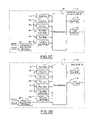
- FIGS. 7A-7F are block diagrams of various embodiments of a CMS sensor cluster.
- FIG. 8 is a front view of an automotive vehicle illustrating various angles according to the present invention.
- FIG. 9 is a side view of an automotive vehicle illustrating various variables thereon.
- FIG. 10 is a top view of a motor vehicle illustrating various operating parameters of a vehicle experiencing a turning maneuver on a road surface.
- FIG. 11 is a block diagram of a supplier/OEM priority system.
- FIG. 12 is a block diagram of a vehicle operations state according to FIG. 11 .
- FIG. 13 is a logic flow diagram of a method for controlling a vehicle dynamic system in accordance with a first embodiment of the present invention.
- FIG. 14 is a logic flow diagram of a method for controlling a vehicle dynamic system in accordance with a second embodiment of the present invention.
- FIG. 15 is a logic flow diagram of a method for controlling a vehicle dynamic system in accordance with a third embodiment of the present invention.
- FIG. 16 is a logic flow diagram of a method for determining a lateral reference velocity.
- FIG. 17 is a logic flow diagram for determining global roll and pitch attitudes.
- FIG. 18 is a logic flow diagram for a fourth embodiment of the invention.
- FIG. 19 is a logic flow diagram for activating a restraint control module.
- the present invention is preferably used in conjunction with vehicle dynamics control systems, which include but are not limited to various control systems such as a yaw stability control system, a roll stability control system, an anti-lock brake system, a traction control system, a hill hold control system, a hill descent/ascent control system, a suspension control system, a steering control system, a drive train control system, an integrated vehicle control system for achieving a balanced vehicle ride and handling performance, the fuel economy, the active and passive safety and the other vehicle level performances.
- vehicle dynamics control systems include but are not limited to various control systems such as a yaw stability control system, a roll stability control system, an anti-lock brake system, a traction control system, a hill hold control system, a hill descent/ascent control system, a suspension control system, a steering control system, a drive train control system, an integrated vehicle control system for achieving a balanced vehicle ride and handling performance, the fuel economy, the active and passive safety and the other vehicle level performances.
- the system is also described with
- Vehicle 10 has front right (FR) and front left (FL) wheel/tires 13 A and 13 B and rear right (RR) wheel/tires 13 C and rear left (RL) wheel/tires 13 D, respectively.
- the vehicle 10 may also have a number of different types of front steering systems 14 a and rear steering systems 14 b , including having each of the front and rear wheels configured with a respective controllable actuator, the front and rear wheels having a conventional type system in which both of the front wheels are controlled together and both of the rear wheels are controlled together, a system having conventional front steering and independently controllable rear steering for each of the wheels, or vice versa.
- the integrated vehicle control system may also be used with other dynamics control systems including active brake control systems, active/semi-active suspension systems, active/semi-active anti-roll bar, active differential system, active front steering system, active rear steering system, powertrain control system or may be used with safety systems such as crash mitigation systems, airbags, side curtains, pretensioners or other safety devices deployed or activated upon detecting the predetermined dynamic conditions of the vehicle.
- dynamics control systems including active brake control systems, active/semi-active suspension systems, active/semi-active anti-roll bar, active differential system, active front steering system, active rear steering system, powertrain control system or may be used with safety systems such as crash mitigation systems, airbags, side curtains, pretensioners or other safety devices deployed or activated upon detecting the predetermined dynamic conditions of the vehicle.
- a sensor system 16 is coupled to the integrated vehicle control system 17 .
- the sensor system 16 may comprise an occupant sensor (OS) group 16 a , an environment sensor (ES) group 16 b , a crash sensor (CS) group 16 c , an actuator-specific sensor (AS) group 16 d , and a motion sensor (MS) group 16 e .
- the sensor system 16 is shown adjacent to a vehicle dynamics box 9 , which represents the physical movement of the vehicle. In other words, the sensors sense the movement of the vehicle and the interactions among different subsystems.
- the vehicle dynamics box 9 are affected by the activation of actuators 12 .
- the integrated vehicle control unit 17 includes an IVC (integrated vehicle control) ECU 18 a , a RCM (restraint control module) ECU 19 a , a suspension control ECU 19 b , a 4 ⁇ 4 control module ECU 19 c , a PCM (powertrain control module) ECU 19 d , a steering control ECU 19 e , and a brake control module ECU 20 .
- the integrated vehicle control system 17 is coupled to and interacts with vehicle CAN network 5 , dedicated (or private) CAN network 6 specified for individual applications and a integrated actuator group 12 .
- the integrated actuator group 12 contains a passive safety module 12 a , a controlled suspension module 12 b , a drivetrain module 12 c , a engine system 12 d , a steering system 2 e and a brake system 12 f.
- a vehicle system level supervision logic developed by the OEMs may be embedded in a integrated vehicle control ECU 18 a and may also be embedded in an ECU from a supplier system.
- the individual control functions developed by the OEMs could also be embedded in the system level ECU such as 18 a owned by the OEMs, or embedded in a supplier's ECU.
- FIG. 2 shows an OEM'S function development 18 b embedded in the brake control module 20 .
- Such OEM developed functions interact with a brake supplier's function partition 21 , which includes a sensor signal processing unit 20 d , function unit 20 c (including brake control functions such as ESC including ABS, RSC, TCS, etc.), priority logic and system level commanding unit 20 b and a actuation distribution and commanding unit 20 a.
- FIGS. 3A-3C where three configurations are included.
- the OEM's development is limited at the vehicle system level, i.e., only the supervisory and monitoring logic are conducted in the system level IVC ECU 18 a .
- the supplier's ECUs are set forth as 15 a, b , and c .
- the OEM involves both the development of new functions such as RSC developed by Ford and a supervisory/monitoring logic 15 d for all the functions associated with each individual ECU from the suppliers including subsystem functions 15 e .
- Such functions are embedded in the system level ECU 18 a and the specific actuators can be driven by the OEM's function through the supplier's ECU.
- FIG. 3C shows a case where the OEM's new development is embedded in one of the suppliers ECUs and the OEM integrates the function developed by the involved ECUs.
- the blocks 15 x and 15 y represent the supplier's partitions and OEM partitions, respectively.
- FIG. 4 a further detailed interaction between the brake ECU 20 , sensors and the actuators are illustrated using an integrated brake control system specified to the current invention is shown.
- the brake ECU 20 contains the OEM's function 18 b and the supplier's function 21 .
- the brake ECU 20 receives measurements from the CMS cluster through a private control area network (CAN) 6 , from the decentralized sensor units such as a brake pressure transducer 23 a , a brake pedal sensor 23 c , a wheel speed sensors 23 d , 23 e , 23 f and 23 g , a steering wheel sensor 23 h and ignition switch 29 .
- the ECU 20 is powered by a vehicle electrical distribution system.
- Brake control module ECU 20 also receives the other signals such as the throttle information through the vehicle CAN network 5 .
- the outputs of ECU 20 drive a hydraulic control unit 24 , which is mechanically connected to a booster assembly 25 .
- the booster assembly 25 is also mechanically connected to a master cylinder/reservoir 26 and a brake pedal assembly 27 .
- the hydraulic control unit 24 also sends brake fluid to each of four brake calipers 28 a , 28 b , 28 c and 28 d .
- 23 a , 23 b , 23 c , 23 d , 23 e , 23 f , and 23 g consists of a subset of the decentralized sensor group; and the actuators 24 , 25 , 26 , 28 a , 28 b , 28 c and 28 d compromise a subset of the integrated actuation system.
- This integrated brake control system is of the type of configuration of FIG. 3C .
- the motion sensor group 16 e in FIG. 2 may be further partitioned based on whether the multiple inertial sensors are packaged at a single location as shown and how the decentralized sensors are arranged in the vehicle. All the sensors, which are packaged in a centralized place in the vehicle body, are denoted as unit 22 which is also called the CMS cluster. All the sensors which are located in various places on the vehicle body consist of a decentralized sensor group 23 .
- a further detailed decentralized sensor group 23 which includes a suspension height sensor set 30 that may include four individual sensors located on the four corners of the vehicle; a vertical acceleration sensor set 31 used by the suspension control; the wheel speed sensors 23 d , 23 e , 23 f and 23 g which are mounted at each wheel and generate signals corresponding to the rotational speed of each wheel; a steering wheel angle sensor 23 h ; a front longitudinal impact acceleration sensor set 32 i which may include a single or multiple longitudinal accelerometers located on the front bumper; a rear longitudinal impact acceleration sensor set 32 j which may include a single or multiple longitudinal accelerometers located on the rear bumper; a left side impact lateral acceleration sensor set 32 k which may include two lateral acceleration sensors located on the front left door and the left C-pillar; a right side impact acceleration sensor set 321 which may contain two lateral accelerometers located on the front right door and the right C pillar.
- the restraint control may include reversible and irreversible safety devices.
- Reversible devices may include seat belt pretensioner, seat, window, sunroof, and door controls; and the other decentralized sensors include but are not limited to the brake pedal sensor 23 b , a brake on/off switch 23 c , tire pressure sensors 33 , an acceleration pedal sensor 34 , and occupant sensors 16 a.
- CMS cluster 50 multiple inertial sensor elements are mounted orthogonally with each other on a printed circuit board (PCB) together with a microcontroller/microprocessor 43 , EEPROM 41 , voltage regulator 39 , watchdog 40 , a clock 48 , and ASICs 49 .
- the PCB is fixed in a sensor cluster housing 50 and sealed by a protective cover.
- the internal data (including measured inertial signals, control loop parameters, temperature signals) transfers between the different sensor elements and the microcontroller and are done by a synchronous bi-directional serial data link with certain baud rate.
- the internal data is then checked by the microcontroller and transformed in a CAN-matrix and transmitted via CAN to the requested ECU.
- the interfaces between the sensor cluster and the external CAN may include four pins, where two of them are used for power supply, and the other two for transferring data via CAN.
- the CMS cluster is preferably mounted directly on the center of gravity of the vehicle body.
- the CMS cluster measures the vehicle body's motion variables along the vehicle's body-fixed frames which are along the directions x,y and z shown in FIG. 1 .
- the frame from b 1 ,b 2 and b 3 is called a body frame, whose origin is located at the center of gravity of the car body, with the b, corresponding to the x axis pointing forward, b 2 corresponding to the y axis pointing off the driving side (to the left), and the b 3 corresponding to the z axis pointing upward.
- the outputs of the CMS cluster are measurements along the sensor cluster's three orthogonal axes, s 1 ,s 2 and s 3 (not shown), which indicate the longitudinal, lateral, and vertical directions of the sensor cluster.
- the vehicle body's longitudinal, lateral and vertical directions are defined through axes b 1 ,b 2 and b 3 .
- the CMS cluster may be mounted such that the axes s 1 ,s 2 and s 3 are exactly along the directions of b 1 ,b 2 and b 3 (shown in FIG. 1 ).
- the longitudinal accelerometer has the sensing direction along b 1 axis
- the lateral accelerometer has the sensing direction along b 2 axis
- the vertical accelerometer has the sensing direction along b 3 axis
- the roll rate sensor has the sensing direction along b 1 axis
- the pitch rate sensor has the sensing direction along b 2 axis
- the yaw rate sensor has the sensing direction along b 3 axis.
- the CMS cluster can be mounted on any location within the vehicle body, however it can also be numerically translated to any specific location of interest, such as the center of gravity of the vehicle body.
- CMS cluster # 1 includes a voltage regulator and monitor 39 , a watchdog 40 , an EEPROM 41 , a CAN controller 42 , a microprocessor 43 , a longitudinal accelerometer 44 a whose output is denoted as a x , a lateral accelerometer 45 a whose output is denoted as a y , a roll rate sensor element 46 a which has dual or multiple resolution in order to achieve multiple operation range and whose output is denoted as ⁇ x , a yaw rate sensor element 47 a which has dual or multiple resolution whose output is denoted as ⁇ z .
- this sensor cluster is the same as the one used in the Ford RSC system only one difference is that both the roll and yaw rate sensors need to have a dual or multiple resolution, which can be achieved through minimum addition of hardware but proper algorithms embedded in the microprocessor 43 . For example, if the angular rate measurements are below certain threshold, a high resolution is used and if the angular rate measurements are above the same threshold a low resolution is used. In this way large roll and yaw rate cases may be monitored by the current sensor cluster. This dual or multiple resolution may be important when the current sensor cluster is used for multiple purposes such as for applications with both the RSC control (with medium range of roll rate) and the rollover curtain deployment (with high range of roll rate).
- the CMS cluster # 2 includes a voltage regulator and monitor 39 , a watchdog 40 , an EEPROM 41 , a CAN controller 42 , a microprocessor 43 , a longitudinal accelerometer 44 b whose output is denoted as a x , a low-g lateral accelerometer 45 b whose output is denoted as a y1 , a high-g lateral accelerometer 46 b whose output is denoted as a y2 , a vertical acceleration 47 b whose output is denoted as a z , a dual or multiple resolution yaw rate sensor element 48 b and whose output is denoted as ⁇ z , and a dual or multiple resolution roll rate sensor element 49 b and whose output is denoted as ⁇ x .
- the sensor cluster may be used for measuring and monitoring vehicle motions for RSC control, side impact detection and rollover curtain deployment.
- only one side impact accelerometer is integrated into this sensor cluster.
- There are other impact sensor units which are required to be mounted on special decentralized locations and which cannot be integrated into such a CMS cluster.
- the CMS cluster # 3 includes a voltage regulator and monitor 39 , a watchdog 40 , an EEPROM 41 , a CAN controller 42 , a microprocessor 43 , a longitudinal accelerometer 44 c whose output is denoted as a x , a lateral accelerometer 45 c whose output is denoted as a y , a dual or multiple resolution roll rate sensor element 46 c whose output is denoted as ⁇ x , a pitch rate sensor element 47 c whose output is denoted as ⁇ y , and a dual or multiple resolution yaw rate sensor element 48 c whose output is denoted as ⁇ y .
- the CMS cluster # 4 includes a voltage regulator and monitor 39 , a watchdog 40 , an EEPROM 41 , a CAN controller 42 , a microprocessor 43 , a longitudinal accelerometer 44 d whose output is denoted as a x , a lateral accelerometer 45 d whose output is denoted as a y , a vertical accelerometer 46 d whose output is denoted as a z , a pitch rate sensor element 47 d whose output is denoted as ⁇ y , a dual or multiple resolution roll rate sensor element 48 d whose output is denoted as ⁇ x , and a dual or multiple resolution yaw rate sensor element 49 d whose output is denoted as ⁇ z .
- this sensor cluster is the same as the so-called IMU (inertial measurement unit), which is widely used in the aerospace industry, except for the dual or multiple resolution requirement for the roll and yaw ang
- the CMS cluster # 5 includes a voltage regulator and monitor 39 , a watchdog 40 , an EEPROM 41 , a CAN controller 42 , a microprocessor 43 , a longitudinal accelerometer 44 e whose output is denoted as a x , a low-g lateral accelerometer 45 e whose output is denoted as a y1 , a high-g lateral accelerometer 46 e whose output is denoted as a y2 , a vertical acceleration 47 e whose output is denoted as a z , a pitch rate sensor element 48 e whose output is denoted as ⁇ y , a dual or multiple resolution yaw rate sensor element 49 e whose output is denoted as ⁇ z , and dual or multiple resolution roll rate sensor element 50 e whose output is denoted as ⁇ x .
- This sensor cluster may be used for vehicle dynamics controls, side impact determination, airbag, and roll
- the CMS cluster # 6 includes a voltage regulator and monitor 39 , a watchdog 40 , an EEPROM 41 , a CAN controller 42 , a microprocessor 43 , a low-g longitudinal accelerometer 44 f whose output is denoted as a x1 , a high-g longitudinal accelerometer 45 f whose output is denoted as a x2 , a low-g lateral accelerometer 46 f whose output is denoted as a y1 , a high-g lateral accelerometer 47 f whose output is denoted as a y2 , a vertical acceleration 48 f whose output is denoted as a z , a pitch rate sensor element 49 f whose output is denoted as ⁇ z , a dual or multiple resolution pitch rate sensor element 50 f whose output is denoted as ⁇ y , and a dual or multiple resolution roll rate sensor element 51 f whose output is
- any of the aforementioned CMS cluster embodiments may be used to characterize the vehicle body motion variables.
- the vehicle longitudinal velocity is denoted as v x
- the vehicle body roll attitude with respect to the sea level as ⁇ x the vehicle body pitch attitude with respect to the sea level as ⁇ y
- FIG. 8 the relationship of the various angles of the vehicle 10 relative to the road surface 11 is illustrated.
- a reference road bank angle ⁇ bank is shown relative to the vehicle 10 on a road surface.
- the vehicle has a vehicle body 10 a and wheel axle 10 b .
- the wheel departure angle ⁇ wda is the angle between the wheel axle and the road.
- the relative roll angle ⁇ xr is the angle between the wheel axle 10 b and the body 10 a .
- the global roll angle ⁇ x is the angle between the horizontal plane (e.g., at sea level) and the vehicle body 10 a.
- the linear bank angle is a bank angle that is calculated more frequently (perhaps in every loop) by subtracting the afore-mentioned relative roll angle from the calculated global roll angle. If all things were slowly changing without drift, errors or the like, the linear bank angle and reference road bank angle terms would be equivalent.
- the vehicle body is subject to a roll moment due to the coupling of the lateral tire force and the lateral acceleration applied to the center of gravity of vehicle body.
- This roll moment causes suspension height variation, which in turn results in a vehicle relative roll angle (also called chassis roll angle or suspension roll angle).
- the relative roll angle is an important variable that is used as an input to the RSC activation criteria and to construct the feedback brake pressure command for RSC function, since it captures the relative roll between the vehicle body and the axle.
- the sum of such a chassis roll angle and the roll angle between wheel axle and the road surface (called wheel departure angle) provides the roll angle between the vehicle body and the average road surface, which is one of the important variables feeding back to the roll stability control module.
- an automotive vehicle 10 is illustrated with various parameters illustrated thereon.
- the side view of automotive vehicle 10 is illustrated.
- a front suspension 52 f and a rear suspension 52 r are illustrated.
- the suspensions are coupled to the body at a respective suspension point 54 f , 54 r .
- the distance from the suspension point 54 f to the center of the wheel is labeled z sh .
- the distance from the center of gravity CG to the front suspension is labeled as b f .
- the distance from the CG to the rear suspension point 54 r is labeled as b r .
- the vertical distance between the center of gravity and the suspension point is labeled as h cg .
- a portion of the body axis b 3 and the road axis r 3 are illustrated.
- the angle therebetween is the relative pitch angle ⁇ yr .
- the rolling radius of the tire is labeled as z w .
- FIG. 10 a top view of vehicle 10 is illustrated.
- the lateral and longitudinal velocities of the center of gravity are v x and v y
- a yaw angular rate is ⁇ z
- a front wheel steering angle is ⁇
- lateral acceleration is represented by a y
- longitudinal acceleration is represented by a x .
- a x dv x ⁇ z v y ⁇ g sin( ⁇ y )
- a y dv y + ⁇ z v x +g sin( ⁇ x )cos( ⁇ y )
- d ⁇ xl ⁇ xl +[ ⁇ y sin( ⁇ x )+ ⁇ z cos( ⁇ x )]tan( ⁇ y ) if in low resolution
- d ⁇ xh ⁇ xh +[ ⁇ y sin( ⁇ x )+ ⁇ z cos( ⁇ x )]tan( ⁇ y ) if in high resolution (1)
- dv x and dv y are the time derivatives of v x and v y .
- d ⁇ x1 and d ⁇ xh are the time derivatives of the low resolution roll angle ⁇ xl and the high resolution roll angle ⁇ xh .
- the yaw rate ⁇ z may be the low resolution yaw rate ⁇ zl or the high resolution yaw rate ⁇ zh , but there is no need to differentiate them in (1).
- the vehicle motion states may not be uniquely determined due to the lack of information in pitch angle. Practically, using dynamics condition screening and the other decentralized sensor units, the pitch angle may be either neglected or be conditionally determined or approximated.
- the RSC roll sensing has been conducted as in a series of patent and patent applications (see for example, U.S. Pat. Nos. 6,556,908, 6,631,317, 6,671,595, 6,718,248, 6,715,240, 6,915,193, the disclosures of which are incorporated by reference herein.).
- the accuracy of the roll angle may be different for different roll rate ranges. For example, for roll rate with magnitudes below 94 deg/sec, the roll angle has high resolution denoted as ⁇ xh . For roll rate magnitude beyond 94 deg/sec, a low resolution roll angle is computed which is denoted as ⁇ xl .
- a x dv x + ⁇ z v y ⁇ z v y ⁇ g sin( ⁇ y )
- a y1 dv y + ⁇ z v x ⁇ x v z +g sin( ⁇ x )cos( ⁇ y )
- a y2 dv x + ⁇ z v x ⁇ x v z +g sin( ⁇ x )cos( ⁇ y )
- dv z is the time derivative of v z .
- d ⁇ xl and d ⁇ xh are the time derivatives of the low resolution roll angle ⁇ xl and the high resolution roll angle ⁇ xh .
- the set of relationships in (2) is similar to the CMS cluster # 1 case in which the vehicle states are theoretically unobservable due to lack of pitch information.
- a x dv x ⁇ z v y ⁇ g sin( ⁇ y )
- a y dv y + ⁇ z v x +g sin( ⁇ x )cos( ⁇ y )
- d ⁇ xl ⁇ xl +[ ⁇ y sin( ⁇ x )+ ⁇ z cos( ⁇ x )]tan( ⁇ y ) if in low resolution
- d ⁇ xh ⁇ xh +[ ⁇ y sin( ⁇ x )+ ⁇ z cos( ⁇ x )]tan( ⁇ y ) if in high resolution
- d ⁇ y ⁇ y cos( ⁇ x ) ⁇ z sin( ⁇ x ) (3)
- d ⁇ y is the time derivative of the pitch angle ⁇ y .
- the vehicle motion variables v x , v y , ⁇ xl , ⁇ xh , ⁇ y may be determined.
- v is a variable used in the suspension heave control while the rest of variables form one embodiment of a minimum set of core vehicle motion states for vehicle stability controls.
- the core set of states depends on various parameters such as the vehicle configuration, desired accuracy, known variables, and the like.
- a x1 dv x ⁇ z v y ⁇ g sin( ⁇ y )
- a x2 dv x ⁇ z v y ⁇ g sin ( ⁇ y )
- a y1 dv y + ⁇ z v x +g sin( ⁇ x )cos( ⁇ y )
- a y2 dv y + ⁇ z v x +g sin( ⁇ x )cos( ⁇ y )
- CMS cluster # 3 , # 4 , # 5 , # 6 are used, then the following variables may be computed which are solely based on the three angular rate sensors
- ⁇ x and ⁇ y may be related to ⁇ xss1 and ⁇ yss1 as in the following
- v ylin is the so-called linear lateral velocity which might be computed from a bicycle model in the following
- v ylin - I z ⁇ d ⁇ [ ⁇ z ] + M z + b f ⁇ M ⁇ [ a y - g ⁇ ⁇ sin ⁇ ( ⁇ x ) ⁇ cos ⁇ ( ⁇ y ) ] b r ⁇ c r ⁇ v x ( 10 )
- M z is the yawing moment due to the stability control, which may be estimated based on the desired yawing moment command, the applied brake pressures at each of the calipers and the estimated road surface ⁇ A
- I z is the yaw momentum of inertia of the vehicle
- M is the vehicle total mass
- b f is the distance from the vehicle center of gravity to the front axle
- b r is the distance from the vehicle center of gravity to the rear axle
- c r is the sum of the nominal cornering stiffness of the rear tires.
- vehicle body global roll and pitch attitudes ⁇ x and ⁇ y may be related to ⁇ sss2 and, ⁇ yss2 as in the following
- ⁇ y sin - 1 ⁇ ( sin ⁇ ( ⁇ yss ⁇ ⁇ 2 ) - ⁇ z ⁇ ⁇ ⁇ ⁇ v y g )
- ⁇ x sin - 1 ⁇ ( sin ⁇ ( ⁇ xss ⁇ ⁇ 2 ) ⁇ cos ⁇ ( ⁇ yss ⁇ ⁇ 2 ) cos ⁇ ( ⁇ y ) - d [ ⁇ ⁇ ⁇ v y ] g ⁇ ⁇ cos ⁇ ( ⁇ y ) ) ( 11 )
- ⁇ v y v y ⁇ v ylin (12)
- Equations in (10) can be simplified to the following
- Equations (13) characterize a simplified functional relationship among the unknowns ⁇ x , ⁇ y . It is evident that ⁇ x , ⁇ y and ⁇ v y may not be decoupled from accelerations in most situations.
- the Euler pitch angle equation is used. Considering the vehicle attitude angles are usually small angles, hence the pitch angle velocity can be directly related to the pitch rate sensor signal, the yaw rate sensor signal and the unknown roll attitude ⁇ x as in the following: d ⁇ y ⁇ y ⁇ z ⁇ x (14)
- Equation (15) and (16) an equation with a sole unknown of the lateral velocity difference may be obtained.
- S p is a function of the lateral and longitudinal accelerations, the vehicle velocity, the yaw rate and the pitch rate but is independent of the roll rate.
- S p is calculated from the measured sensor signals and the calculated variables from the measured sensor signals.
- the magnitude of S p implies the magnitude of the sideslip tendency of the vehicle, and hence the name sliding index.
- S r is a function of the lateral and longitudinal accelerations, the vehicle velocity, the yaw rate and the roll rate but is independent of the pitch rate.
- the sensor failures may be detected through sensor self tests and sensor electronic monitoring. Both sensor self test and the sensor electronic monitoring are conducted by checking if the measurement from a sensor of interest is within the sensor specifications which are usually defined through the lower and upper bounds and various change rate limitations of the sensor signal. Since it is possible for a specific sensor to have a failure without violating the sensor specification, it may be desirable to conduct in-spec sensor failure check.
- a roll rate sensor plausibility can be determined through the sensors such as a lateral accelerometer, a longitudinal accelerometer, a pitch rate sensor and a yaw rate sensor.
- sensors such as a lateral accelerometer, a longitudinal accelerometer, a pitch rate sensor and a yaw rate sensor.
- ⁇ ⁇ ⁇ v ⁇ yp ⁇ ( t ) 1 ⁇ ⁇ z ⁇ ( t ) ⁇ ⁇ ⁇ 0 t ⁇ S p ⁇ ( ⁇ ) 2 ⁇ ⁇ ⁇ z ⁇ ( ⁇ ) ⁇ ⁇ sgn ⁇ ( ⁇ z ⁇ ( ⁇ ) ) ⁇ d ⁇ ( 21 )
- the roll rate signal may be estimated through the following based on (13) and the general kinematics equation shown in (1)-(6):
- This singular point could cause numerical discrepancies since a small amount of noise in the involved signals may lead to signal or large errors.
- the following iterative algorithm captures such relationship and the way to calculate ⁇ v yp k+1
- the lateral velocity delta ⁇ v yp k+1 of the vehicle is a function of the sliding index and the sequential difference ⁇ z k+1 of the measured yaw rate signals as set forth in the following:
- the vehicle pitch attitude angle ⁇ y2 k+1 may be calculated from current value of the steady state pitch angle ⁇ yss2 k+1 and the current value of the measured yaw rate ⁇ z k+1 .
- Those current digital values obey the second Equation of (22) in the following digital form
- ⁇ x ⁇ ⁇ 2 k + 1 ⁇ xss ⁇ ⁇ 2 k + 1 - 1 g ⁇ d ⁇ [ ⁇ ⁇ ⁇ v yp k + 1 ] ⁇ ⁇ ⁇ T ( 28 )
- the unknown roll rate ⁇ x k+1 of the vehicle can be calculated from the roll attitude angle ⁇ x2 k+1 the current value of the sequential difference ⁇ x2 k+1 of this calculated roll attitude angle, the current value of the measured pitch rate ⁇ y k+1 and the current value of the measured yaw rate ⁇ z k+1 is set forth in the following:
- ⁇ v yr may be obtained which is independent of the pitch rate.
- the corresponding estimated attitudes are denoted as ⁇ x3 and ⁇ y3 .
- the pitch rate signal may be calculated in the following
- the vehicle body's global attitudes may be determined in steady state conditions as ⁇ xss1 , ⁇ yss1 in (7) or as ⁇ xss2 , ⁇ yss2 in (9).
- the steady state conditions may then be characterized. That is, if
- the vehicle's steering input velocity d ⁇ x is limited under a certain threshold
- the vehicle yaw rate ⁇ z is limited under a certain threshold and the vehicle's lateral acceleration is under certain threshold
- computation in (9) may be used to characterize the vehicle body's global roll and pitch angles. Notice that the aforementioned conditions might not be steady state conditions, but might be rather non-aggressive dynamic conditions where the vehicle's dynamics are in the linear range.
- Such conditions are related to the driving conditions of mild driver steering inputs and normal road surface conditions.
- the reference lateral velocity of the vehicle is denoted as v yref , whose computation will be discussed in the next section.
- the vehicle reference global attitudes may then be calculated as
- the reference signals defined in this invention are those variables which may be used to capture some portion of the real value of the interested variables. For example, the low frequency portion of a signal. In the aforementioned attitude computation, the reference lateral velocity v yref is already used. Another reference variable is the reference longitudinal velocity, which is determined based on the four-wheel speed sensor signals.
- the relative roll attitude angle of a vehicle body with respect to the average road surface is related to the sensor signals through suspensions.
- M susp the moment due to vertical suspension forces
- M latforce the moment due to lateral tire force
- the relative roll angle is ⁇ xr
- the total vehicle suspension roll spring rate is K roll and the total vehicle suspension roll damping rate is D roll
- M latforce might be calculated based on sensor measurements and the calculated variables.
- the total lateral force applied to the vehicle body is generated from the lateral tire forces through suspensions. This total lateral force generates a lateral acceleration, which is measured by the acceleration sensor mounted on the center of gravity of the vehicle body.
- the variable a y is the lateral acceleration of the vehicle body center of gravity
- M s is the vehicle sprung mass.
- ⁇ M s ⁇ h cg K roll
- ⁇ ⁇ I x K roll ( 48 )
- ⁇ and ⁇ need to be calculated in a practical implementation. Since the vehicle parameter M s , I x and K roll are all varied, an accurate relative roll angle is possible if those parameters are reflected accurately in a real-time computation.
- the estimated vehicle sprung mass is an output from the VPD (vehicle parameter determination) unit 92 in ISS system.
- K roll lookup_table( a y ) (51)
- the normalized roll angle may be determined in step 166 using Equation (53) with the calculated NM roll using the lookup table calculated coefficients ⁇ and ⁇ , (44) can be used to solve for relative roll angle.
- Such relative roll angle satisfies
- T ROLL ⁇ ( s ) K roll K roll + D roll ⁇ s ( 55 )
- the relative pitch computation may be similarly performed.
- M susp the moment due to vertical suspension forces
- M longforce the moment due to lateral tire force
- the relative pitch angle ⁇ yr could be obtained by passing this scaled vertical suspension force-induced pitch moment to a first order filter same as in the relative roll angle computation.
- M longforce may be determined based on the sensor measurements or the calculated variables.
- ⁇ acc ⁇ circle around (M) ⁇ x lookup_table ⁇ acc ( a x )
- dec ⁇ circle around (M) ⁇ x lookup_table ⁇ dec ( a x )
- ⁇ acc ⁇ circle around (M) ⁇ x lookup_table ⁇ acc ( a x )
- dec ⁇ circle around (M) ⁇ x lookup_table ⁇ dcc ( a x ) (63)
- the normalized vertical suspension force induced pitch moment NM pitch may be determined.
- T PITCH ⁇ ( s ) K pitch K pitch + D pitch ⁇ ( s ) ( 65 )
- the vehicle system may include a safety system or other vehicle system.
- Safety systems may include a yaw control system or a rollover control system. Of course, more than one system may be controlled at a time.
- the integrated vehicle control module 17 of FIG. 2 may be coupled to the integrated sensor group 16 d , which includes sensors 16 a - 16 e depicted in FIG. 11 through a vehicle bus 5 .
- the integrated vehicle control module 17 includes a number of sensing algorithms and a collection of feedback control algorithms which perform multiple control functions by activating available actuators based on the variables calculated in the sensing algorithms.
- the sensing algorithms receive the available sensor signals or the past values of the calculated variables to characterize the interaction among the driver, the vehicle and the external environment of the vehicle including the road and other moving and non-moving objects.
- the integrated vehicle control module 17 includes an integrated sensing system 152 .
- the integrated sensing (ISS) system 152 has various sensing algorithms therein.
- the integrated sensing system 152 identifies the vehicle's operational states and the driver's intention during travel using a vehicle operation state determination 154 .
- An external hazard determination is provided by external hazard determination 156 .
- the vehicle operation state determination 154 and external hazard determination 156 are coupled together. Based upon the information processed and calculated from the integrated sensing system 152 , the vehicle dynamics features such as controllability and stability may be readily determined.
- Various OEM's functions 153 such as RSC, driving assistance and tripped rollover mitigation may be coupled to the integrated sensing system 152 .
- the determination of the controllability and stability is performed in a dynamics feature classification module 160 .
- the dynamics feature classification 160 will also involve information from the sensor measurements or the calculated variables from the measurements regarding actuator specific dynamics as illustrated by arrow 162 .
- the information processed in the dynamics feature classification module 160 is coupled to the control function priority determination and arbitration module 164 and the actuation priority determination and arbitration module 166 .
- a collection of control functions from the auto suppliers resides in a control module 168 . It is illustrated coupled to the OEM's functions 153 and ultimately to the integrated sensing system 152 , the dynamics feature classification 160 , and a control function priority determination and arbitration block 164 .
- the supplier's control function module 153 receives signals from the various sensors, the integrated sensing system 152 , and the dynamics feature classification 160 . Based upon those signals, the necessary feedback control commands in the vehicle level or actuator level may be provided in both function module 153 and 168 .
- Vehicle level control may, for example, comprise controlling the roll moment in a roll stability control system.
- Actuator level control for example, may comprise controlling the anti-lock brake system.
- the supplier's control function module 168 is a broad category for an anti-lock brake system 170 , the traction control system 172 , a yaw stability control system 174 , a roll stability control system 176 , cornering deceleration regulation unit 178 , driving assistance unit 180 , road adaptive driving adjustment unit 182 , an adaptive cruise control unit 184 , lane departure correction unit 186 , and tripped rollover mitigation unit 188 .
- various other functions may be evident to those skilled in the art.
- the supplier's control function module 168 may be coupled to priority logic system command module 20 b and actuation and distribution command module 20 a as set forth in FIG. 2 . Also, box 20 b may be coupled to an actuator priority determination and arbitration module 166 . Notice that the suppliers are responsible for the control logic in 20 a and 20 b.
- the vehicle level control from both the OEM's control function module 153 and the supplier's control function module 168 may, for example, be the total yaw moment for counteracting the vehicle's yaw motion or the total roll moment for counteracting the vehicle's roll motion.
- the vehicle level control command may be decomposed into actuator level commands such that the vehicle level control may best be achieved, when the involved actuators activate according to the demanded actuator level commands in a coordinated way.
- the vehicle level control command may come from different function requests.
- a function decomposition may be used and may include control functions of significance for the vehicle dynamics and controls.
- the dynamics feature classification (DFC) unit 160 may determine that the vehicle operates under controllable dynamics. If so, both 153 and 168 may request one or more feedback control commands such as roll moment feedback (vehicle level command for rollover protection), pitch moment feedback (vehicle level command for pitchover prevention), yaw moment feedback (vehicle level command for spin-out prevention), lateral acceleration regulation (vehicle level command), longitudinal acceleration regulation (vehicle level command), sideslip angle regulation (vehicle level command for vehicle lateral sliding prevention), and longitudinal slip regulation (actuator level command).
- roll moment feedback vehicle level command for rollover protection
- pitch moment feedback vehicle level command for pitchover prevention
- yaw moment feedback vehicle level command for spin-out prevention
- lateral acceleration regulation vehicle level command
- longitudinal acceleration regulation vehicle level command
- sideslip angle regulation vehicle level command for vehicle lateral sliding prevention
- longitudinal slip regulation actuator level command
- an aggressive steering induced rollover event may start from a large yaw motion of the vehicle and then develop into a larger roll motion and a potentially larger lateral sliding. Coordination, prioritization, and arbitration of those different control demands may be required in block 164 .
- each may be requested for achieving various functions.
- controlled brakes, controlled anti-roll-bar, controlled front wheel steering, and controlled rear wheel steering may all be used to perform certain roll stability control functions.
- Actuator priority determination and arbitration unit 166 is dedicated to determine the proper actuators to most effectively realize the vehicle control command received from the control function priority determination and arbitration unit 164 .
- the integrated vehicle control module commands the individual control modules to achieve the command.
- the integrated vehicle control module 17 acts as a local controller.
- the RSC function in the integrated control module 17 generates a counteracted roll moment and a control command in terms of caliper pressure at certain brake locations.
- the brake hydraulic control unit shown in FIG. 4 are modified such that the brake pressure command can be followed by the brake caliper or calipers through a closed loop strategy.
- the dynamics feature classification module 160 determines whether the vehicle is operating under stable or unstable dynamics, or controllable or uncontrollable dynamics conditions. It also establishes appropriate control threshold values for various combinations of the stability and controllability using stable, unstable but controllable, unstable and uncontrollable dynamics conditions.
- FIG. 12 the integrated sensing system 152 of FIG. 2 is illustrated in further detail.
- the vehicle operation state determination 154 may include sensor signal compensation 200 , abnormal state monitoring 202 , and a sensor plausibility check 204 .
- the sensor signal compensation, abnormal state monitoring and sensor plausibility check are used to correct and adjust the various sensor signals.
- the output of the sensor signal compensation 200 , abnormal state monitoring 202 , and sensor plausibility check 204 may be coupled to a vehicle state estimator 210 .
- the vehicle state estimate includes a vehicle global and relative attitude determination 212 .
- the relative/global attitude determination 212 may be characterized by the vehicle body Euler angles with respect to sea level or with respect to the average road surface.
- a directional vehicle velocity block 214 is used to determine the absolute vehicle velocity projected along the vehicle body fixed longitudinal and latitudinal direction.
- a vehicle reference signal generator 216 may also be included in the vehicle state estimator 210 .
- the vehicle state estimator 210 may also include a force and torque estimation block 218 that estimates the forces and torques acting on the vehicle.
- a normal loading determination 220 determines the normal loading acting at each of the wheels of the vehicle.
- a vehicle operational parameter determination 222 may also be provided within the vehicle state estimator 210 .
- the vehicle operational parameter determination 222 may include the determinations of the vehicle loading, tire rolling radii, vehicle mass, and various other parameters.
- a road state estimator 228 may also be coupled within the vehicle operation state determination 154 .
- the road state estimator 228 is illustrated coupled to an internal data communication mechanism 150 .
- the road state estimator 228 may include a surface friction determination 230 that generates a signal corresponding to the road surface friction level. Surface friction is sometimes referred to as surface mu ( ⁇ ).
- a road bank determination unit 232 may also be provided within the road state estimator 228 .
- the road bank determination unit 232 determines the bank angle of the road on which the vehicle is driven.
- the bank angle of the road is the lateral or sideways angle of the road in a direction perpendicular to the normal or intended travel direction of the road.
- a road incline determination 234 is also provided within the road state estimator 228 .
- the inclination determination 234 determines the angular inclination of the road in the direction of normal vehicle travel on the road.
- a road curvature determination 236 may also be provided within the road estimator block 228 .
- the road curvature determination determines the radius of curvature of the road on which the vehicle is traveling.
- the road curvature information may be coupled to the environmental sensors such as external cameras used in active cruise control (ACC) or pre-crash sensing. Sometimes, GPS information may be used to extract the road curvature information.
- the vehicle operational state determination 154 may include a driver's intention determination block 240 .
- the driver's intention determination block 240 may provide an indication as to the desired vehicle motion path or the desired vehicle moving rate (such as the desired yaw rate of the vehicle) from the driver.
- a dominated dynamics determination block 242 may also be coupled to the internal data communication mechanism 150 and receive various information therefrom.
- the dominated dynamics determination unit 242 is used to classify the main control direction of the vehicle dynamics if there are multiple functions requested at the same time. For example, if a roll dominated motion is set forth, roll stability control is likely to provide a majority control in order to control the roll motion of the vehicle. Although the single dominated vehicle dynamics is possible, many times the vehicle operates under combined dynamics.
- a large vehicle yawing on a high friction road surface may cause a large roll motion.
- External hazard determination 156 of the integrated sensing system 152 is also illustrated in FIG. 12 .
- the external hazard determination block includes a moving object classification 248 , an accident avoidance determination 250 , a pre-crash determination 252 , and another unit 254 which takes care of detecting all the other hazards.
- a moving object may be classified into one of a number of predetermined categories, including a vehicle or size of vehicle and the direction of the vehicle.
- An accident avoidance determination may be made based upon the dynamic conditions in the heading of both the host vehicle and a target vehicle.
- a pre-crash determination determines whether or not a collision is predictable.
- step 302 signals from the various sensors are received.
- step 304 the magnitude of the lateral acceleration of the vehicle is checked. If it exceeds a lateral acceleration threshold, step 400 will be executed, otherwise, step 306 is executed.
- step 306 the magnitude of the longitudinal acceleration is checked. If the longitudinal acceleration exceeds the longitudinal acceleration threshold, step 400 will be conducted, otherwise, step 308 will be conducted.
- step 308 the magnitude of the roll rate is checked with respect to a roll rate threshold. If it exceeds the roll rate threshold, step 400 will proceed, otherwise, step 310 will be executed.
- step 310 the magnitude of yaw rate is checked.
- step 400 If the yaw rate exceeds the yaw rate threshold, then step 400 will be executed, otherwise, step 312 will be executed.
- the above steps aim to single out the extreme vehicle dynamics which are associated with crash or collision.
- other schemes may be possible which may involve checking the magnitude of the combined accelerations or angular rates or may involve using both environmental sensor signals from 16 b and crash sensor signals from 16 c in FIG. 2 to conduct such predetermination of crash or collision vehicle dynamics.
- a sensor plausibility check 312 is conducted for roll rate sensor, pitch rate sensor, yaw rate sensor, longitudinal accelerometer, lateral accelerometer, vertical accelerometer or subsets of this six types of sensors.
- the algorithm used in this block may be, but is not limited to those described in the sensor plausibility check section of this invention.
- step 314 if the sensor signals are not plausible, step 316 is executed in which sensor fault processing logic is performed. Otherwise, sensor signal compensation 318 is performed.
- Sensor signal compensation may include compensating the sensor signals for various offsets including temperature dependent sensor drift compensation, resting sensor offset compensation and dynamic sensor offset compensation. Sensor signal compensation performed in 318 might also include the sensor misalignment compensation (one method for performing such compensation can be found in U.S. Pat. No.
- step 320 the vehicle's relative attitudes are determined.
- step 322 the vehicle linear lateral velocity is computed based on a linear (may be time varying) lateral dynamics model of the vehicle, such as the computation using (10). Such a linear lateral velocity may also be obtained through the vehicle's true tire lateral forces and the tire cornering stiffness coefficients. The true tire forces might be also determined in the force and torque estimation module 218 shown in FIG. 12 , which is beyond the bicycle model used in (10).
- step 324 two sliding indexes as defined in (18) and (19) are calculated. Such sliding indexes are calculated based on relationship (9) and roll, pitch and yaw angular rate signals. Based on those two sliding indexes and the two ordinary differential equations defined in (17) and (20), a reference lateral velocity of the vehicle may be obtained in step 326 by using (43).
- step 328 the global roll and pitch angles of the vehicle are calculated, and the vehicle directional velocities are then computed in step 330 . After step 330 , it arrives at node 340 .
- step 320 can be further depicted in FIG. 14 . It starts in step 320 a where it receives sensor signals and the calculated signals, or the past values of the interested variables.
- step 320 b and 320 c the roll gradient a and the roll acceleration coefficient ⁇ are determined which are either computed through prescribed lookup tables as in (52) using formulas in (48), or they are adaptively computed in real time by compensating the vehicle loading changes as in U.S. patent application Ser. No. 10/966,395 filed Oct. 15, 2004, and incorporated by reference herein.
- step 320 d the normalized roll moment is computed as in (47). Such a normalized roll moment is then passed through a filter shown in (31) and the final relative roll angle is obtained as in step 320 e.
- step 320 f the longitudinal acceleration is checked to see if the vehicle is accelerating or decelerating. If the vehicle is accelerating, step 320 g is performed where the pitch gradient and the pitch acceleration coefficient for an accelerating vehicle are determined. They may be computed through prescribed lookup tables as in (63) using formulas in (61), or they may be adaptively computed in real time by compensating the vehicle loading changes as in U.S. patent application Ser. No. 11/010,863, filed Dec. 13, 2004, and incorporated by reference herein.
- step 320 i the final pitch gradient and the final pitch acceleration coefficient are set.
- step 320 j the normalized pitch moment is determined as in (38). The normalized pitch moment is then filtered as shown in (41) to obtain the final relative pitch in step 320 k.
- step 320 h is conducted where the pitch gradient and the pitch acceleration coefficient for a decelerating vehicle are determined.
- the values may be passed through a first order filter which reflects the roll damping model through Equations (48) and (52).
- the above estimated variables may be used as feedback to the vehicle dynamics control systems to achieve the vehicle yaw stability control, the vehicle sideslip control, and the vehicle roll stability control.
- step 326 The details of step 326 are further described in FIG. 16 , where in step 326 a , an adaptive gain ⁇ is adjusted based on the vehicle driving conditions. In step 326 b , another adaptive gain ⁇ is adjusted based on the vehicle driving conditions. Those two gains are used to assemble the two independent characterizations of the lateral velocity dynamics (17) and (20) together with a linear lateral velocity so as to obtain the dynamics shown in (66).
- the digital implementation of the solution for (66) is performed in step 326 c, d and e , which are summarized in (67). Notice that ⁇ and ⁇ play important roles here for (67) to achieve robust computation.
- the linear lateral velocity is a good indication of the true lateral velocity, hence the gain ⁇ will be picked at its maximum value. That is, the computation in (43) will most likely to converge to the linear lateral velocity.
- step 328 the-first set of global roll and pitch angles are computed, which can accurately characterize the true vehicle attitudes during steady state driving conditions. Such computations use the formula in (7), i.e., uses the algebraic relationship among the roll, pitch and yaw angular rates.
- step 328 b the second set of global roll and pitch angles are computed using the formula in (9), i.e., they use the accelerations together with the computed variables such as the linear lateral velocity, the longitudinal velocity and yaw angular rate.
- Such computations may only characterize the vehicle's true attitudes when the vehicle is driven in its linear dynamics range.
- step 328 c the reference lateral velocity and the second set of attitudes are used together to compute the so-called reference attitudes using formula (36).
- the vehicle driving conditions are discriminated in step 328 d based on a series of functional conditions shown in (35).
- step 328 e the feedback gains are determined for the attitude errors between the final computation of the vehicle attitudes and the first set of attitudes, the second set of attitudes, and the reference attitudes.
- step 328 f uses those gains to generate a linear combination of the three sets of attitude errors generated in step 328 e and feed them back to Euler dynamics shown in (63).
- the final error feedback structures are shown in (64) for roll attitude and in (65) for pitch attitudes.
- step 328 g the global attitudes are finally calculated based on the digital implementation of (64) and (65).
- step 342 the computation in FIG. 16 continues in step 342 where the road surface mu is determined.
- the road bank and road inclination are determined in step 344 and 346 respectively.
- the road curvature is determined in step 348 .
- step 350 the driver's intent is determined.
- the dominated vehicle dynamics discrimination is performed in step 352 .
- step 354 if the roll motion is determined to be a dominated motion direction, the roll stability control will be prepared and performed through wheel lift detection (step 360 ), wheel departure angle computation (step 362 ), enabling the RSC controller and preparing the RSC controller (step 364 ) and command the actuator through priority logic (step 20 b ).
- step 356 is conducted where yaw motion is checked for dominance. If the yaw motion is dominated motion, then the yaw stability control is performed through under-steer/over-steer determination (step 370 ), enable YSC controller and prepare YSC controller (step 372 ), under-steer/over-steer control command determination, and the final actuator commanding (step 20 b ).
- step 356 the sideslip dominance will be checked in step 358 . If there is a large vehicle lateral sliding, the side slip control will be initiated through sideslip and its velocity computation (step 380 ), enable sideslip controller (step 382 ), over-steer control command (step 384 ) and priority logic (step 20 b ). If the vehicle's sideslip angle and/or its velocity are below some thresholds, step 400 will be performed.
- FIG. 18 only shows a single motion dominance case. Those motions might happen simultaneously and more than one motion may dominate the total vehicle motion. In such cases, it is not hard to find that the thresholds used in checking motion dominance for steps 354 , 356 and 358 might need to be a function of the accelerations, roll and yaw rate and vehicle sideslip angle. From this point of view, the aforementioned strategy does not lose its generality. That is, if none are very dominant based on the thresholds, a blending of various controls may be performed. The amount of blending and type of blending may be vehicle specific based on various conditions.
- a look up table may be determined based on the conditions, the contents of which are determined during the testing phase of the vehicle in much the same way as engines and transmissions are calibrated.
- One specific blending method is maximum rule. That is, during an RSC event, if the roll characterization, the yaw characterization and sideslip angle are all greater than certain blended thresholds, the brake control pressure at the front outside wheel will be the maximum of the three feedback brake pressures generated for roll stability control, yaw stability control and the sideslip control.
- RSC control command usually takes the priority over the other functions most of the time. Hence prioritization could be also thought as one of the blending methods used.
- step 410 is conducted for determining the external hazard. If the external hazard level is below a threshold at step 420 , the process goes back to its starting point at step 300 shown in FIG. 13 . Otherwise, step 430 is performed where crash mitigation system is initiated.
- step 440 control commands are sent to brake control module and powertrain control module to stop the vehicle.
- step 450 the passive safety system, such as the restraint control module, are prepared. If in step 460 , the restraint control module determines that the passive safety device activation criteria exceed a series of threshold, the restraint control module will activate appropriate passive safety countermeasures. If the passive safety device activation criteria do not exceed thresholds, step 400 is restarted.
Landscapes
- Engineering & Computer Science (AREA)
- Transportation (AREA)
- Mechanical Engineering (AREA)
- Physics & Mathematics (AREA)
- Automation & Control Theory (AREA)
- Mathematical Physics (AREA)
- Remote Sensing (AREA)
- General Physics & Mathematics (AREA)
- Radar, Positioning & Navigation (AREA)
- Aviation & Aerospace Engineering (AREA)
- Regulating Braking Force (AREA)
- Control Of Driving Devices And Active Controlling Of Vehicle (AREA)
- Vehicle Body Suspensions (AREA)
Priority Applications (7)
| Application Number | Priority Date | Filing Date | Title |
|---|---|---|---|
| US11/230,275 US7590481B2 (en) | 2005-09-19 | 2005-09-19 | Integrated vehicle control system using dynamically determined vehicle conditions |
| GB0616383A GB2431735B (en) | 2005-09-19 | 2006-08-18 | Integrated Vehicle Control System Using Dynamically Determined Vehicle Conditions |
| DE102006042961A DE102006042961A1 (de) | 2005-09-19 | 2006-09-13 | Dynamisch bestimmte Fahrzeugzustände verwendendes, integriertes Fahrzeugsteuersystem |
| US12/536,515 US8442720B2 (en) | 2005-09-19 | 2009-08-06 | Integrated vehicle control system using dynamically determined vehicle conditions |
| US12/536,517 US8311706B2 (en) | 2005-09-19 | 2009-08-06 | Integrated vehicle control system using dynamically determined vehicle conditions |
| US12/536,514 US8346452B2 (en) | 2005-09-19 | 2009-08-06 | Integrated vehicle control system using dynamically determined vehicle conditions |
| US12/536,518 US8352143B2 (en) | 2005-09-19 | 2009-08-06 | Integrated vehicle control system using dynamically determined vehicle conditions |
Applications Claiming Priority (1)
| Application Number | Priority Date | Filing Date | Title |
|---|---|---|---|
| US11/230,275 US7590481B2 (en) | 2005-09-19 | 2005-09-19 | Integrated vehicle control system using dynamically determined vehicle conditions |
Related Child Applications (4)
| Application Number | Title | Priority Date | Filing Date |
|---|---|---|---|
| US12/536,514 Division US8346452B2 (en) | 2005-09-19 | 2009-08-06 | Integrated vehicle control system using dynamically determined vehicle conditions |
| US12/536,517 Division US8311706B2 (en) | 2005-09-19 | 2009-08-06 | Integrated vehicle control system using dynamically determined vehicle conditions |
| US12/536,518 Division US8352143B2 (en) | 2005-09-19 | 2009-08-06 | Integrated vehicle control system using dynamically determined vehicle conditions |
| US12/536,515 Division US8442720B2 (en) | 2005-09-19 | 2009-08-06 | Integrated vehicle control system using dynamically determined vehicle conditions |
Publications (2)
| Publication Number | Publication Date |
|---|---|
| US20070067085A1 US20070067085A1 (en) | 2007-03-22 |
| US7590481B2 true US7590481B2 (en) | 2009-09-15 |
Family
ID=37081157
Family Applications (5)
| Application Number | Title | Priority Date | Filing Date |
|---|---|---|---|
| US11/230,275 Expired - Fee Related US7590481B2 (en) | 2005-09-19 | 2005-09-19 | Integrated vehicle control system using dynamically determined vehicle conditions |
| US12/536,515 Active 2028-01-01 US8442720B2 (en) | 2005-09-19 | 2009-08-06 | Integrated vehicle control system using dynamically determined vehicle conditions |
| US12/536,517 Active 2027-08-14 US8311706B2 (en) | 2005-09-19 | 2009-08-06 | Integrated vehicle control system using dynamically determined vehicle conditions |
| US12/536,514 Active 2027-08-04 US8346452B2 (en) | 2005-09-19 | 2009-08-06 | Integrated vehicle control system using dynamically determined vehicle conditions |
| US12/536,518 Active 2027-09-12 US8352143B2 (en) | 2005-09-19 | 2009-08-06 | Integrated vehicle control system using dynamically determined vehicle conditions |
Family Applications After (4)
| Application Number | Title | Priority Date | Filing Date |
|---|---|---|---|
| US12/536,515 Active 2028-01-01 US8442720B2 (en) | 2005-09-19 | 2009-08-06 | Integrated vehicle control system using dynamically determined vehicle conditions |
| US12/536,517 Active 2027-08-14 US8311706B2 (en) | 2005-09-19 | 2009-08-06 | Integrated vehicle control system using dynamically determined vehicle conditions |
| US12/536,514 Active 2027-08-04 US8346452B2 (en) | 2005-09-19 | 2009-08-06 | Integrated vehicle control system using dynamically determined vehicle conditions |
| US12/536,518 Active 2027-09-12 US8352143B2 (en) | 2005-09-19 | 2009-08-06 | Integrated vehicle control system using dynamically determined vehicle conditions |
Country Status (3)
| Country | Link |
|---|---|
| US (5) | US7590481B2 (zh-CN) |
| DE (1) | DE102006042961A1 (zh-CN) |
| GB (1) | GB2431735B (zh-CN) |
Cited By (50)
| Publication number | Priority date | Publication date | Assignee | Title |
|---|---|---|---|---|
| US20070213898A1 (en) * | 2006-03-08 | 2007-09-13 | Honda Motor Co., Ltd. | Control apparatus for vehicle having cooperative control unit |
| US20080051962A1 (en) * | 2005-04-06 | 2008-02-28 | Yasuhiro Nakai | Controller for Operation of Vehicle and Control Method for the Same |
| US20080059034A1 (en) * | 2006-08-30 | 2008-03-06 | Ford Global Technologies, Llc | Integrated control system for stability control of yaw, roll and lateral motion of a driving vehicle using an integrated sensing system to determine a sideslip angle |
| US20080208515A1 (en) * | 2005-07-26 | 2008-08-28 | Peugeot Citroen Automobiles Sa | System for Determining Inflating Pressures of Tyres Mounted on a Motor Vehicle Front and Rear Wheels |
| US20080262680A1 (en) * | 2007-04-02 | 2008-10-23 | Trw Automotive U.S. Llc | Apparatus and method for detecting vehicle rollover using an enhanced algorithm having lane departure sensor inputs |
| US20090132112A1 (en) * | 2005-04-07 | 2009-05-21 | Frank Ewerhart | Plausibilization of Sensor Signals in the Event of a Collision |
| US20090292424A1 (en) * | 2008-05-22 | 2009-11-26 | Ford Global Technologies, Llc | Vehicle rollover detection |
| US20100017070A1 (en) * | 2008-07-15 | 2010-01-21 | Ford Global Technologies, Llc | Stability control and inclined surface control using a common signal source |
| US20100078917A1 (en) * | 2008-09-30 | 2010-04-01 | Takata Corporation | Side impact crash detection system |
| US20100256872A1 (en) * | 2009-04-07 | 2010-10-07 | Ford Global Technologies, Llc | System and method for deploying a safety system |
| US20110054733A1 (en) * | 2009-08-28 | 2011-03-03 | Hyundai Motor Company | Gravity sensor circuit system for vehicle |
| US20110077823A1 (en) * | 2009-03-03 | 2011-03-31 | Toyota Jidosha Kabushiki Kaisha | Steering control device for a vehicle |
| US20110282558A1 (en) * | 2010-05-12 | 2011-11-17 | Mando Corporation | Adaptive cruise control method on incline |
| US8150531B2 (en) | 2008-07-11 | 2012-04-03 | Medtronic, Inc. | Associating therapy adjustments with patient posture states |
| US8175720B2 (en) | 2009-04-30 | 2012-05-08 | Medtronic, Inc. | Posture-responsive therapy control based on patient input |
| US8209028B2 (en) | 2008-07-11 | 2012-06-26 | Medtronic, Inc. | Objectification of posture state-responsive therapy based on patient therapy adjustments |
| US8219206B2 (en) | 2008-07-11 | 2012-07-10 | Medtronic, Inc. | Dwell time adjustments for posture state-responsive therapy |
| US8231555B2 (en) | 2009-04-30 | 2012-07-31 | Medtronic, Inc. | Therapy system including multiple posture sensors |
| US8280517B2 (en) | 2008-09-19 | 2012-10-02 | Medtronic, Inc. | Automatic validation techniques for validating operation of medical devices |
| US8332041B2 (en) | 2008-07-11 | 2012-12-11 | Medtronic, Inc. | Patient interaction with posture-responsive therapy |
| US8388555B2 (en) | 2010-01-08 | 2013-03-05 | Medtronic, Inc. | Posture state classification for a medical device |
| US8396565B2 (en) | 2003-09-15 | 2013-03-12 | Medtronic, Inc. | Automatic therapy adjustments |
| US8401666B2 (en) | 2008-07-11 | 2013-03-19 | Medtronic, Inc. | Modification profiles for posture-responsive therapy |
| US8437861B2 (en) | 2008-07-11 | 2013-05-07 | Medtronic, Inc. | Posture state redefinition based on posture data and therapy adjustments |
| WO2013095907A1 (en) * | 2011-12-20 | 2013-06-27 | Caterpillar Inc. | System and method for controlling slip |
| US8504150B2 (en) | 2008-07-11 | 2013-08-06 | Medtronic, Inc. | Associating therapy adjustments with posture states using a stability timer |
| US8579834B2 (en) | 2010-01-08 | 2013-11-12 | Medtronic, Inc. | Display of detected patient posture state |
| US8600614B2 (en) | 2011-02-05 | 2013-12-03 | Ford Global Technologies, Llc | System and method for integrated control of vehicle control systems |
| US8708934B2 (en) | 2008-07-11 | 2014-04-29 | Medtronic, Inc. | Reorientation of patient posture states for posture-responsive therapy |
| US20140379222A1 (en) * | 2011-11-07 | 2014-12-25 | Robert Bosch Gmbh | Method and device for analyzing a collision of a vehicle |
| US8924096B2 (en) | 2012-10-31 | 2014-12-30 | Caterpillar Inc. | Implement controller having angular rate correction |
| US9050471B2 (en) | 2008-07-11 | 2015-06-09 | Medtronic, Inc. | Posture state display on medical device user interface |
| US9327070B2 (en) | 2009-04-30 | 2016-05-03 | Medtronic, Inc. | Medical device therapy based on posture and timing |
| US9333965B2 (en) | 2010-04-30 | 2016-05-10 | American Axle & Manufacturing, Inc. | Control strategy for operating a locking differential |
| US9333975B2 (en) | 2011-02-05 | 2016-05-10 | Ford Global Technologies, Llc | Method and system to detect and mitigate customer dissatisfaction with performance of automatic mode selection system |
| US9357949B2 (en) | 2010-01-08 | 2016-06-07 | Medtronic, Inc. | User interface that displays medical therapy and posture data |
| US20160161944A1 (en) * | 2014-12-05 | 2016-06-09 | Charles A. Leonard | Vehicle leveling systems, devices and methods and computer program products for leveling vehicles using smart devices |
| US9387852B2 (en) | 2010-09-23 | 2016-07-12 | Audi Ag | Method for adjusting the spatial position of the roll axis of a motor vehicle |
| US9566441B2 (en) | 2010-04-30 | 2017-02-14 | Medtronic, Inc. | Detecting posture sensor signal shift or drift in medical devices |
| US9737719B2 (en) | 2012-04-26 | 2017-08-22 | Medtronic, Inc. | Adjustment of therapy based on acceleration |
| US9752299B2 (en) * | 2015-04-30 | 2017-09-05 | Caterpillar Inc. | System having pitch-adjusted rotational speed measurement |
| US9764734B1 (en) | 2015-03-26 | 2017-09-19 | Hydro-Gear Limited Partnership | Stability control system |
| US9878738B2 (en) | 2012-03-28 | 2018-01-30 | Robert Bosch Gmbh | Non-linear compensation controller for active steering system in a vehicle |
| US9907959B2 (en) | 2012-04-12 | 2018-03-06 | Medtronic, Inc. | Velocity detection for posture-responsive therapy |
| US9956418B2 (en) | 2010-01-08 | 2018-05-01 | Medtronic, Inc. | Graphical manipulation of posture zones for posture-responsive therapy |
| US10058031B1 (en) | 2015-02-28 | 2018-08-28 | Hydro-Gear Limited Partnership | Lawn tractor with electronic drive and control system |
| US10392007B1 (en) | 2015-03-26 | 2019-08-27 | Hydro-Gear Limited Partnership | Stability control system |
| US10407058B2 (en) * | 2015-01-15 | 2019-09-10 | Yancheng Institute Of Technology | Automobile cornering rollover prevention method and system |
| US10471264B2 (en) | 2005-12-02 | 2019-11-12 | Medtronic, Inc. | Closed-loop therapy adjustment |
| DE102019201358A1 (de) | 2019-02-04 | 2020-08-06 | Ford Global Technologies, Llc | Verfahren zum Abschätzen der Wankbewegung eines Kraftfahrzeuges |
Families Citing this family (138)
| Publication number | Priority date | Publication date | Assignee | Title |
|---|---|---|---|---|
| DE102005004894A1 (de) * | 2005-02-03 | 2006-08-17 | Robert Bosch Gmbh | Auslöseverfahren zur Aktivierung einer Lateralgeschwindigkeitsschätzung für Insassenschutzvorrichtungen |
| JP4504838B2 (ja) * | 2005-03-01 | 2010-07-14 | 本田技研工業株式会社 | 横転判定装置 |
| US20070088479A1 (en) * | 2005-10-19 | 2007-04-19 | Trw Automotive U.S. Llc | Apparatus with sensor assembly for sensing a vehicle crash condition and associated method |
| JP5011866B2 (ja) * | 2006-01-23 | 2012-08-29 | 日産自動車株式会社 | 横すべり角推定装置、自動車、及び横すべり角推定方法 |
| JP5018149B2 (ja) * | 2006-04-26 | 2012-09-05 | 日産自動車株式会社 | 運転者感覚調整装置 |
| JP2009536594A (ja) * | 2006-05-09 | 2009-10-15 | ロッキード・マーチン・コーポレイション | 移動性トラクション制御システム及び方法 |
| EP2021197B1 (en) * | 2006-05-11 | 2018-03-21 | TRW Automotive U.S. LLC | Apparatus and method for detecting vehicle rollover using enhanced sensor inputs and processing architecture |
| US7739014B2 (en) * | 2006-08-30 | 2010-06-15 | Ford Global Technolgies | Integrated control system for stability control of yaw, roll and lateral motion of a driving vehicle using an integrated sensing system to determine a final linear lateral velocity |
| US7970512B2 (en) * | 2006-08-30 | 2011-06-28 | Ford Global Technologies | Integrated control system for stability control of yaw, roll and lateral motion of a driving vehicle using an integrated sensing system with pitch information |
| JP4985373B2 (ja) * | 2007-03-15 | 2012-07-25 | 株式会社アドヴィックス | 車両の運動制御装置 |
| JP4882848B2 (ja) * | 2007-04-23 | 2012-02-22 | アイシン精機株式会社 | 統合車体挙動制御装置 |
| US8029074B2 (en) * | 2007-05-21 | 2011-10-04 | Goodrich Corporation | Fault tolerant aircraft braking control using alternate wheel speed information |
| US8560217B2 (en) * | 2007-06-15 | 2013-10-15 | Cadec Global, Inc. | System and method for predicting vehicle rollover using position tracking |
| US20090076683A1 (en) * | 2007-09-13 | 2009-03-19 | Chee Siong Lim | Vehicle anti-rollover system and method |
| US8589049B2 (en) * | 2007-12-03 | 2013-11-19 | Lockheed Martin Corporation | GPS-based system and method for controlling vehicle characteristics based on terrain |
| US20090143937A1 (en) * | 2007-12-04 | 2009-06-04 | Lockheed Martin Corporation | GPS-based traction control system using wirelessly received weather data |
| US8145402B2 (en) * | 2007-12-05 | 2012-03-27 | Lockheed Martin Corporation | GPS-based traction control system and method using data transmitted between vehicles |
| US20090187324A1 (en) * | 2008-01-23 | 2009-07-23 | Jianbo Lu | Vehicle Stability Control System and Method |
| US8033955B2 (en) * | 2008-03-06 | 2011-10-11 | Toyota Motor Engineering & Manufacturing North America, Inc. | Methods and systems for regulating hill descent speed of an electric vehicle |
| US20090299546A1 (en) * | 2008-05-28 | 2009-12-03 | Hac Aleksander B | Dynamic-based method of estimating the absolute roll angle of a vehicle body |
| EP2288895B1 (en) * | 2008-06-18 | 2020-03-18 | TRW Automotive U.S. LLC | Method and apparatus for determining a vehicle pitch-over condition |
| US8284069B2 (en) * | 2008-07-15 | 2012-10-09 | Cadec Global, Inc. | System and method for detecting a boundary crossing event |
| US20100131141A1 (en) * | 2008-11-21 | 2010-05-27 | Gm Global Technology Operations, Inc. | Bank angle estimation via vehicle lateral velocity with force tables |
| JP5146542B2 (ja) * | 2008-12-26 | 2013-02-20 | トヨタ自動車株式会社 | 走行路推定装置、及び当該装置で用いられる走行路推定方法 |
| US20100211249A1 (en) * | 2009-02-13 | 2010-08-19 | Mcclellan Scott | System and method for detecting vehicle maintenance requirements |
| US8244442B2 (en) * | 2009-02-17 | 2012-08-14 | Lockheed Martin Corporation | System and method for stability control of vehicle and trailer |
| US8229639B2 (en) * | 2009-02-17 | 2012-07-24 | Lockheed Martin Corporation | System and method for stability control |
| US8352120B2 (en) * | 2009-02-17 | 2013-01-08 | Lockheed Martin Corporation | System and method for stability control using GPS data |
| DE102009013895B4 (de) * | 2009-03-19 | 2011-06-30 | Knorr-Bremse Systeme für Nutzfahrzeuge GmbH, 80809 | Fahrzeug mit einer Einrichtung zur Regelung der Fahrdynamik mit in einer gemeinsamen Baueinheit integriertem Lenkwinkelsensor, Gierratensensor und Beschleunigungssensor |
| US9278693B2 (en) * | 2009-03-24 | 2016-03-08 | Ford Global Technologies, Llc | System and method for improving vehicle performance on grade |
| CN102470874B (zh) * | 2009-07-07 | 2013-09-04 | 丰田自动车株式会社 | 车辆控制装置及运算装置 |
| WO2011021088A1 (en) * | 2009-08-18 | 2011-02-24 | Toyota Jidosha Kabushiki Kaisha | Vehicle control system |
| US8577550B2 (en) * | 2009-10-05 | 2013-11-05 | Ford Global Technologies, Llc | System for vehicle control to mitigate intersection collisions and method of using the same |
| US9403415B2 (en) * | 2009-10-12 | 2016-08-02 | Ford Global Technologies | GPS based pitch sensing for an integrated stability control system |
| TWI394944B (zh) * | 2009-10-22 | 2013-05-01 | Univ Nat Chiao Tung | 車輛姿態估測系統與方法 |
| US8260498B2 (en) * | 2009-10-27 | 2012-09-04 | GM Global Technology Operations LLC | Function decomposition and control architecture for complex vehicle control system |
| US9285485B2 (en) * | 2009-11-12 | 2016-03-15 | GM Global Technology Operations LLC | GPS-enhanced vehicle velocity estimation |
| EP3290310B1 (en) * | 2009-12-25 | 2021-08-18 | Yamaha Hatsudoki Kabushiki Kaisha | Rider characteristics determining method |
| US8633828B2 (en) * | 2010-02-01 | 2014-01-21 | Analog Devices, Inc. | System and method for safing and monitoring a plurality of vehicle sensors |
| US8473151B2 (en) | 2010-03-30 | 2013-06-25 | Toyota Motor Engineering & Manufacturing North America, Inc. | Excursion prevention methods and systems |
| DE102010015425A1 (de) * | 2010-04-19 | 2011-10-20 | Audi Ag | Vorrichtung zum Betreiben einer Antriebseinheit eines Kraftfahrzeugs |
| CA2797499A1 (en) * | 2010-04-30 | 2011-11-03 | Bombardier Recreational Products Inc. | Method for controlling a wheeled vehicle |
| DE102010026916A1 (de) * | 2010-07-13 | 2012-01-19 | Man Truck & Bus Ag | Verfahren und Vorrichtung zum Erkennen und Kompensieren einer von einem Fahrzeug durchfahrenen Fahrbahnquerneigung |
| US10207719B2 (en) * | 2010-07-19 | 2019-02-19 | Nxp Usa, Inc. | Use of multiple internal sensors for measurements validation |
| DE102010039949A1 (de) * | 2010-08-30 | 2012-03-01 | Bayerische Motoren Werke Aktiengesellschaft | Verfahren zur Erkennung fehlender Fahreraktivität am Lenkrad eines Kraftfahrzeugs |
| US8725346B2 (en) * | 2010-12-15 | 2014-05-13 | Hong Kong Productivity Council | Collision severity determination system and method |
| US8863256B1 (en) | 2011-01-14 | 2014-10-14 | Cisco Technology, Inc. | System and method for enabling secure transactions using flexible identity management in a vehicular environment |
| JP5229341B2 (ja) * | 2011-02-28 | 2013-07-03 | 株式会社デンソー | アクセルペダル誤操作対応装置およびアクセルペダル誤操作対応装置用のプログラム |
| WO2012143238A2 (de) * | 2011-04-19 | 2012-10-26 | Meissner Marita | Fahrdynamikregelung mit gnss und ins |
| US20140092252A1 (en) * | 2011-05-12 | 2014-04-03 | Magna Electronics Inc. | System and method for annotating video |
| DE102011076043A1 (de) * | 2011-05-18 | 2012-11-22 | Ford Global Technologies, Llc | Regelungssystem für ein Kraftfahrzeug mit einem Kofferaufbau und Kraftfahrzeug |
| US9346428B2 (en) * | 2011-11-22 | 2016-05-24 | Autoliv Asp, Inc. | System and method for determining when to deploy a vehicle safety system |
| JP5741719B2 (ja) * | 2012-01-25 | 2015-07-01 | 日産自動車株式会社 | 車両の制御装置及び車両の制御方法 |
| US9415657B2 (en) * | 2012-01-25 | 2016-08-16 | Nissan Motor Co., Ltd. | Vehicle control device and vehicle control method |
| JP5970832B2 (ja) * | 2012-01-26 | 2016-08-17 | 日産自動車株式会社 | ロールレイト推定装置 |
| JP5884237B2 (ja) * | 2012-02-21 | 2016-03-15 | オートリブ日信ブレーキシステムジャパン株式会社 | 車両挙動制御装置 |
| DE102012004929A1 (de) | 2012-03-10 | 2013-09-12 | Audi Ag | Fahrerassistenzsystem für ein Kraftfahrzeug |
| US8818606B2 (en) * | 2012-04-16 | 2014-08-26 | GM Global Technology Operations LLC | System and method for vehicle lateral control |
| KR101350303B1 (ko) * | 2012-04-30 | 2014-01-14 | 주식회사 만도 | 스마트 크루즈 컨트롤 시스템 및 그 컨트롤 방법 |
| FI124565B (fi) * | 2012-05-31 | 2014-10-15 | Ponsse Oyj | Metsätyöyksikön vakautus |
| TW201412585A (zh) * | 2012-09-18 | 2014-04-01 | Automotive Res & Testing Ct | 車輛彎道翻覆預防系統及其方法 |
| US20140114442A1 (en) * | 2012-10-22 | 2014-04-24 | The Boeing Company | Real time control system management |
| JP5846401B2 (ja) * | 2012-10-31 | 2016-01-20 | トヨタ自動車株式会社 | 車両の走行制御装置 |
| ES2699245T3 (es) | 2012-11-07 | 2019-02-08 | Polaris Inc | Vehículo con suspensión con control continuo de amortiguación |
| US9205717B2 (en) | 2012-11-07 | 2015-12-08 | Polaris Industries Inc. | Vehicle having suspension with continuous damping control |
| DE102012024971A1 (de) * | 2012-12-20 | 2013-07-04 | Daimler Ag | Verfahren zum kombinierten Bestimmen eines momentanen Wankwinkels eines Kraftfahrzeugs und einer momentanen Fahrbahn-Querneigung eines von dem Kraftfahrzeug befahrenen kurvenförmigen Fahrbahnabschnitts |
| CN103921796B (zh) * | 2013-01-14 | 2017-07-28 | 博世汽车部件(苏州)有限公司 | 车胎爆裂时车辆动力学状态的控制方法和设备 |
| US9869003B2 (en) | 2013-02-26 | 2018-01-16 | Ati Properties Llc | Methods for processing alloys |
| CN105339227B (zh) | 2013-05-02 | 2019-06-18 | 通用汽车环球科技运作有限责任公司 | 使用三轴惯性测量装置的集成斜度和侧倾估计 |
| CN104281152A (zh) * | 2013-07-04 | 2015-01-14 | 上海九鹰电子科技有限公司 | 遥控模型运动模式的控制方法和装置、以及遥控模型 |
| ITTO20130584A1 (it) * | 2013-07-11 | 2015-01-12 | Fiat Ricerche | Stima della massa di un veicolo e della pendenza della strada |
| GB2516698B (en) * | 2013-07-30 | 2017-03-22 | Jaguar Land Rover Ltd | Vehicle distributed network providing feedback to a user |
| US11111552B2 (en) | 2013-11-12 | 2021-09-07 | Ati Properties Llc | Methods for processing metal alloys |
| CN103745113B (zh) * | 2014-01-16 | 2017-03-29 | 大陆泰密克汽车系统(上海)有限公司 | 用于确定信号链的残余失效率的方法 |
| US9283825B2 (en) | 2014-02-25 | 2016-03-15 | Isam Mousa | System, method, and apparatus to prevent commercial vehicle rollover |
| JP6206258B2 (ja) * | 2014-03-06 | 2017-10-04 | 富士通株式会社 | 軌跡推定装置、軌跡推定方法およびプログラム |
| CN105611981B (zh) * | 2014-07-30 | 2018-04-03 | 株式会社小松制作所 | 搬运车辆及搬运车辆的控制方法 |
| US9725093B2 (en) * | 2014-09-23 | 2017-08-08 | Cummins Inc. | Vehicle controls including dynamic vehicle mass and road grade estimation during vehicle operation |
| KR101678583B1 (ko) * | 2014-10-29 | 2016-11-22 | 현대모비스 주식회사 | 차량 간 통신을 이용한 차간 거리 제어 시스템 및 그 제어방법 |
| CA2965309C (en) | 2014-10-31 | 2024-01-23 | Polaris Industries Inc. | System and method for controlling a vehicle |
| US10094003B2 (en) | 2015-01-12 | 2018-10-09 | Ati Properties Llc | Titanium alloy |
| KR101619418B1 (ko) * | 2015-02-26 | 2016-05-18 | 현대자동차 주식회사 | 차량의 제동 장치 및 방법 |
| CN113183701A (zh) | 2015-05-15 | 2021-07-30 | 北极星工业有限公司 | 多用途车辆 |
| US9371073B1 (en) * | 2015-06-19 | 2016-06-21 | GM Global Technology Operations LLC | Real-time determination of tire normal forces |
| US9964048B2 (en) * | 2015-07-28 | 2018-05-08 | Caterpillar Inc. | Systems and methods for adaptive throttle filtering |
| JP6502782B2 (ja) * | 2015-07-31 | 2019-04-17 | Kyb株式会社 | バンク角度検知装置およびバンク角度検知方法 |
| CN105035091B (zh) * | 2015-08-10 | 2017-09-29 | 北京经纬恒润科技有限公司 | 一种车身姿势变化的检测方法及装置 |
| CN109070825B (zh) * | 2016-03-15 | 2021-08-31 | 福特全球技术公司 | 使用车辆动力学来确定撞击位置 |
| EP3445622A4 (en) | 2016-04-22 | 2020-01-22 | Clearmotion, Inc. | METHOD AND DEVICE FOR STRAIGHT CONTROL, AND A FAST-RESPONDING VEHICLE |
| US9886841B1 (en) | 2016-04-27 | 2018-02-06 | State Farm Mutual Automobile Insurance Company | Systems and methods for reconstruction of a vehicular crash |
| JP6569647B2 (ja) | 2016-11-11 | 2019-09-04 | トヨタ自動車株式会社 | 車両の車線逸脱防止装置 |
| MX2019005524A (es) | 2016-11-18 | 2019-11-21 | Polaris Inc | Vehiculo que tiene suspension ajustable. |
| WO2018101210A1 (ja) * | 2016-11-29 | 2018-06-07 | ヤマハ発動機株式会社 | リーン車両の路面垂直方向軸周りの角速度取得装置 |
| US10406884B2 (en) | 2017-06-09 | 2019-09-10 | Polaris Industries Inc. | Adjustable vehicle suspension system |
| US10207559B2 (en) * | 2017-06-15 | 2019-02-19 | GM Global Technology Operations LLC | Systems and methods for the real-time determination of tire normal forces |
| JP6868102B2 (ja) * | 2017-06-27 | 2021-05-12 | 本田技研工業株式会社 | 車両制御装置 |
| TWI635302B (zh) * | 2017-07-18 | 2018-09-11 | 李綱 | 載具即時精準定位系統 |
| US10112727B1 (en) * | 2017-08-29 | 2018-10-30 | Kitty Hawk Corporation | Actuator monitoring system using inertial sensors |
| US10901432B2 (en) * | 2017-09-13 | 2021-01-26 | ClearMotion, Inc. | Road surface-based vehicle control |
| US11136021B1 (en) * | 2017-10-18 | 2021-10-05 | Zoox, Inc. | Independent control of vehicle wheels |
| CN109808666B (zh) * | 2017-11-21 | 2021-06-04 | 中车唐山机车车辆有限公司 | 一种列车车厢制动控制方法、列车车厢和列车 |
| US10183542B1 (en) | 2017-12-11 | 2019-01-22 | Cnh Industrial America Llc | Suspension control system providing orientation control for an agricultural machine |
| US10436622B2 (en) | 2017-12-11 | 2019-10-08 | Cnh Industrial America Llc | Suspension control system providing closed loop control of hydraulic fluid volumes for an agricultural machine |
| US10569612B2 (en) | 2017-12-11 | 2020-02-25 | Cnh Industrial America Llc | Suspension control system providing tire height corrections for an agricultural machine |
| US10730359B2 (en) | 2017-12-11 | 2020-08-04 | Cnh Industrial America Llc | Suspension control system providing suspension height corrections for an agricultural machine |
| CN113968289A (zh) | 2018-01-10 | 2022-01-25 | 北极星工业有限公司 | 无级变速器 |
| CN110412995B (zh) * | 2018-04-26 | 2022-05-24 | 宇通客车股份有限公司 | 一种基于控制力矩陀螺的车辆防侧翻方法 |
| US10946736B2 (en) | 2018-06-05 | 2021-03-16 | Polaris Industries Inc. | All-terrain vehicle |
| CN110920605B (zh) * | 2018-08-31 | 2021-05-14 | 华为技术有限公司 | 一种车辆控制方法及设备 |
| US10987987B2 (en) | 2018-11-21 | 2021-04-27 | Polaris Industries Inc. | Vehicle having adjustable compression and rebound damping |
| US11281236B2 (en) * | 2019-01-25 | 2022-03-22 | Textron Innovations Inc. | Alternative yaw control |
| DE102019205110A1 (de) * | 2019-03-27 | 2020-10-01 | Vitesco Technologies Germany Gmbh | Automatische Feststellbremse für ein Fahrrad |
| DE102019003238B4 (de) * | 2019-05-08 | 2023-04-20 | Mercedes-Benz Group AG | Fahrzeugortung durch Kartenabgleich unter Berücksichtigung eines Straßenprofils |
| JP7274103B2 (ja) * | 2019-06-04 | 2023-05-16 | マツダ株式会社 | 車両姿勢制御装置 |
| US11447112B2 (en) * | 2019-06-04 | 2022-09-20 | Mazda Motor Corporation | Vehicle attitude control system |
| WO2020255748A1 (ja) * | 2019-06-21 | 2020-12-24 | 日立オートモティブシステムズ株式会社 | 車両制御装置 |
| US11260803B2 (en) | 2019-07-26 | 2022-03-01 | Polaris Industries Inc. | Audio system for a utility vehicle |
| CN112477781B (zh) * | 2019-09-12 | 2022-08-26 | 华为技术有限公司 | 实现汽车中电子控制功能的系统、方法以及汽车 |
| US11541882B2 (en) * | 2019-09-24 | 2023-01-03 | Volvo Car Corporation | Low-impact collision detection |
| DE102019127129A1 (de) * | 2019-10-09 | 2021-04-15 | WABCO Global GmbH | Arbeitsfahrzeug für den Einsatz in der Landwirtschaft und Verfahren zu dessen Steuerung |
| CN110901323B (zh) * | 2019-11-06 | 2022-05-24 | 江苏科技大学 | 汽车车身高度调节系统 |
| CN110843746B (zh) * | 2019-11-28 | 2022-06-14 | 的卢技术有限公司 | 一种基于强化学习的防抱死刹车控制方法及系统 |
| US20210302189A1 (en) * | 2020-03-26 | 2021-09-30 | Toyota Motor Engineering & Manufacturing North America, Inc. | Remote Control of Vehicle via Smartphone and Gesture Input |
| CN113525347B (zh) * | 2020-04-13 | 2024-01-26 | 广州汽车集团股份有限公司 | 一种车辆控制方法、装置及计算机可读存储介质 |
| US11332152B2 (en) * | 2020-05-29 | 2022-05-17 | GM Global Technology Operations LLC | Method and apparatus for determining a velocity of a vehicle |
| WO2022016155A1 (en) | 2020-07-17 | 2022-01-20 | Polaris Industries Inc. | Adjustable suspensions and vehicle operation for off-road recreational vehicles |
| JP2022025229A (ja) * | 2020-07-29 | 2022-02-10 | カワサキモータース株式会社 | 移動経路生成システム、移動経路生成プログラム及び移動経路生成方法 |
| WO2022098357A1 (en) * | 2020-11-05 | 2022-05-12 | Ford Global Technologies, Llc | Suspension system with comprehensive pitch stability control |
| US11618440B2 (en) * | 2020-11-09 | 2023-04-04 | Guangzhou Automobile Group Co., Ltd. | Method for controlling ESA system of a vehicle and ESA system |
| CN112406853B (zh) * | 2020-11-25 | 2022-05-10 | 东风越野车有限公司 | 轮毂电机驱动越野车横摆与侧倾稳定性集成控制方法 |
| CN112793560B (zh) * | 2020-12-31 | 2022-08-19 | 北京理工大学 | 基于转矩矢量控制的无人驾驶车安全性与操稳性控制方法 |
| CN112874315B (zh) * | 2021-01-13 | 2022-11-04 | 深圳市奇虎智能科技有限公司 | 平衡车的运动控制方法、装置、设备及存储介质 |
| TWI779911B (zh) * | 2021-10-28 | 2022-10-01 | 財團法人車輛研究測試中心 | 穩煞系統及其方法 |
| US11618349B1 (en) | 2021-11-08 | 2023-04-04 | Toyota Motor North America, Inc. | Transport-related occupant adjustments |
| FR3129474A1 (fr) * | 2021-11-23 | 2023-05-26 | Aml Systems | Method and system for estimating a total pitch angle of a motor vehicle. |
| EP4234354A1 (de) * | 2022-02-23 | 2023-08-30 | KNORR-BREMSE Systeme für Nutzfahrzeuge GmbH | Verfahren zur plausibilisierung einer drehrate eines fahrzeugaufbaus eines fahrzeugs und vorrichtung zur ausführung des verfahrens |
| CN114475575B (zh) * | 2022-04-15 | 2022-07-12 | 北京理工大学 | 一种汽车控制系统和方法以及汽车 |
| CN115452411B (zh) * | 2022-09-02 | 2024-04-12 | 合肥工业大学 | 智能网联汽车线控底盘全硬件在环的协调控制方法及应用 |
Citations (102)
| Publication number | Priority date | Publication date | Assignee | Title |
|---|---|---|---|---|
| US2917126A (en) | 1957-04-04 | 1959-12-15 | Nolan Phillips | Driving control safety mechanism for tractors |
| US3604273A (en) | 1968-11-25 | 1971-09-14 | Aviat Electric Ltd | Angular rate sensor |
| US3608925A (en) | 1969-05-07 | 1971-09-28 | Peter H Murphy | Apparatus for offsetting centrifugal force affecting motor vehicles |
| US3797893A (en) | 1971-07-06 | 1974-03-19 | Daimler Benz Ag | Brake force control system for vehicles |
| US3899028A (en) | 1972-03-30 | 1975-08-12 | Systron Donner Corp | Angular position sensing and control system, apparatus and method |
| US3948567A (en) | 1975-02-12 | 1976-04-06 | The Bendix Corporation | Sway control means for a trailer |
| US3972543A (en) | 1974-12-06 | 1976-08-03 | The Bendix Corporation | Combination vehicle yaw stabilizer |
| US4023864A (en) | 1973-09-20 | 1977-05-17 | Lang Davis Industries, Inc. | Automatic stability control system with strain gauge sensors |
| USRE30550E (en) | 1975-11-06 | 1981-03-24 | Durrell U. Howard | Automatic trailer sway sensing and brake applying system |
| US4294113A (en) | 1980-02-04 | 1981-10-13 | Dresser Industries, Inc. | Anti-surge system for gases and other media |
| US4480714A (en) | 1982-03-05 | 1984-11-06 | Toyo Umpanki Co., Ltd. | System for preventing carrier from turning sideways |
| US4548079A (en) | 1982-12-14 | 1985-10-22 | Wabco Westinghouse Fahrzeugbremsen Gmbh | Method and apparatus to automatically determine the weight or mass of a moving vehicle |
| US4592565A (en) | 1984-10-17 | 1986-06-03 | Leo Eagle | Apparatus for detecting an overturning moment in a moving vehicle, and jackknifing in a trailer-truck combination |
| US4597462A (en) | 1984-02-02 | 1986-07-01 | Honda Giken Kogyo Kabushiki Kaisha | Steering system for vehicles |
| US4624476A (en) | 1984-01-24 | 1986-11-25 | Mitsubishi Jidosha Kogyo Kabushiki Kaisha | Vehicle suspension apparatus |
| US4650212A (en) | 1985-03-20 | 1987-03-17 | Mazda Motor Corporation | Vehicle suspension system |
| US4679808A (en) | 1985-03-15 | 1987-07-14 | Nissan Motor Co., Ltd. | Vehicle motion estimating system |
| US4690553A (en) | 1979-06-29 | 1987-09-01 | Omron Tateisi Electronics Co. | Road surface condition detection system |
| US4696489A (en) | 1985-01-14 | 1987-09-29 | Nissan Motor Company, Limited | Automotive suspension system with variable damping characteristics |
| US4705130A (en) | 1984-01-31 | 1987-11-10 | Nissan Motor Co., Ltd. | Method of controlling vehicle |
| US4712807A (en) | 1985-02-06 | 1987-12-15 | Toyota Jidosha Kabushiki Kaisha | Vehicle active suspension system incorporating acceleration detecting means |
| US4761022A (en) | 1986-03-08 | 1988-08-02 | Toyota Jidosha Kabushiki Kaisha | Suspension controller for improved turning |
| US4765649A (en) | 1986-03-17 | 1988-08-23 | Toyota Jidosha Kabushiki Kaisha | System for vehicle body roll control detecting and compensating for changes of loaded vehicle weight |
| US4767588A (en) | 1985-04-13 | 1988-08-30 | Nissan Motor Co., Ltd. | Vehicle control system for controlling side slip angle and yaw rate gain |
| US4778773A (en) | 1986-06-10 | 1988-10-18 | Nec Corporation | Method of manufacturing a thin film transistor |
| US4797823A (en) | 1985-10-22 | 1989-01-10 | Toyota Jidosha Kabushiki Kaisha | System for vehicle body roll control performing suspension hardness control |
| US4809183A (en) | 1986-03-01 | 1989-02-28 | Robert Bosch Gmbh | Speed control system for motor vehicles operating in a curved path |
| US4827416A (en) | 1985-09-13 | 1989-05-02 | Nissan Motor Company, Limited | Method and system for controlling automotive suspension system, particularly for controlling suspension characteristics in accordance with road surface conditions |
| US4846496A (en) | 1984-01-24 | 1989-07-11 | Mitsubishi Jidosha Kogyo Kabushiki Kaisha | Vehicle suspension apparatus |
| US4872116A (en) | 1986-01-10 | 1989-10-03 | Nissan Motor Company, Limited | Vehicle motion estimating system of hybrid type |
| US4888696A (en) | 1987-03-31 | 1989-12-19 | Nissan Motor Company, Limited | Actively controlled automotive suspension system with acceleration and angular velocity dependent anti-pitching and/or anti-rolling feature |
| US4898431A (en) | 1988-06-15 | 1990-02-06 | Aisin Seiki Kabushiki Kaisha | Brake controlling system |
| US4930082A (en) | 1987-07-28 | 1990-05-29 | Mitsubishi Jidosha Kogyo Kabushiki Kaisha | Control apparatus for a vehicular suspension system |
| US4951198A (en) | 1987-10-15 | 1990-08-21 | Mazda Motor Corporation | Friction detecting device for vehicles |
| US4960292A (en) | 1988-11-01 | 1990-10-02 | Jaguar Cars Limited | Air bag restraint systems |
| US4964679A (en) | 1988-02-23 | 1990-10-23 | Lucas Industries Public Limited Co. | Monitoring method and apparatus for a brake system of heavy-duty vehicles |
| US4967865A (en) | 1988-02-13 | 1990-11-06 | Daimler-Benz Ag | Supplementary steering system |
| US4976330A (en) | 1987-12-22 | 1990-12-11 | Fuji Jukogyo Kabushiki Kaisha | Vehicle traction control system for preventing vehicle turnover on curves and turns |
| US4998593A (en) | 1989-03-31 | 1991-03-12 | Aisin Seiki Kabushiki Kaisha | Steering and brake controlling system |
| US5002142A (en) | 1989-04-14 | 1991-03-26 | Trw Inc. | Vehicle steering system |
| US5033770A (en) | 1988-09-30 | 1991-07-23 | Fuji Jukogyo Kabushiki Kaisha | Controlling apparatus for active suspension system for automotive vehicle |
| US5058017A (en) | 1987-11-05 | 1991-10-15 | Hitachi, Ltd. | System for control of vehicle suspension |
| US5066041A (en) | 1987-06-27 | 1991-11-19 | Baverische Motoren Werke Ag | Control system for stabilizing the rolling of a vehicle |
| US5085458A (en) | 1989-08-09 | 1992-02-04 | Nissan Motor Company, Limited | Attitude change suppression control system for active suspension system with high sensitivity of vehicular attitude change |
| US5088040A (en) | 1989-01-18 | 1992-02-11 | Nissan Motor Company, Limited | Automotive control system providing anti-skid steering |
| US5089967A (en) | 1987-08-10 | 1992-02-18 | Nippondenso Co., Ltd. | Auxiliary steering system associated with anti-skid control system for use in motor vehicle |
| US5097917A (en) | 1987-12-26 | 1992-03-24 | Honda Giken Kogyo Kabushiki Kaisha | Steering system of vehicle |
| US5159553A (en) | 1988-09-13 | 1992-10-27 | Aisin Seiki Kabushiki Kaisha | Steering control apparatus |
| US5163319A (en) | 1987-11-11 | 1992-11-17 | Messerschmitt-Bolkow-Blohm Gmbh | Method and a device for recognizing the condition of a road |
| US5189920A (en) | 1991-03-21 | 1993-03-02 | Electronics & Space Corp. | Corner stability testing apparatus |
| US5200896A (en) | 1989-09-07 | 1993-04-06 | Honda Giken Kogyo Kabushiki Kaisha | Method for estimating longitudinal acceleration or deceleration of a vehicle body |
| US5208749A (en) | 1989-08-11 | 1993-05-04 | Hitachi, Ltd. | Method for controlling active suspension system on the basis of rotational motion model |
| US5217248A (en) | 1989-03-22 | 1993-06-08 | Detroit Steel Products Co. Inc. | Vehicle suspension system |
| US5224765A (en) | 1990-12-21 | 1993-07-06 | Nissan Motor Co., Ltd. | Control system for distributing braking forces applied to left and right wheels in automotive vehicles |
| US5228757A (en) | 1990-07-02 | 1993-07-20 | Nissan Motor Co., Ltd. | System for controlling behavior of vehicle during braking and during a steering maneuver |
| US5230396A (en) | 1988-09-13 | 1993-07-27 | Aisin Seiki Kabushiki Kaisha | Steering control apparatus |
| US5239868A (en) | 1989-05-19 | 1993-08-31 | Matsushita Electric Industrial Co., Ltd. | Angular rate detecting device |
| US5247466A (en) | 1990-03-29 | 1993-09-21 | Hitachi, Ltd. | Angular rate detection apparatus, acceleration detection apparatus and movement control apparatus, of moving body |
| US5261503A (en) | 1990-07-11 | 1993-11-16 | Aisin Seiki Kabushiki Kaisha | Adaptive steering control system |
| US5265020A (en) | 1990-04-20 | 1993-11-23 | Mazda Motor Corporation | Torque distribution control apparatus for four wheel drive |
| US5274576A (en) | 1989-04-21 | 1993-12-28 | Group Lotus Plc | Apparatus for measuring the yaw rate of a vehicle |
| US5278761A (en) | 1992-11-12 | 1994-01-11 | Ford Motor Company | Method for vehicular wheel spin control that adapts to different road traction characteristics |
| US5282134A (en) | 1991-08-19 | 1994-01-25 | Automotive Systems Laboratory, Inc. | Slant transform/signal space crash discriminator |
| US5297646A (en) | 1990-04-18 | 1994-03-29 | Nissan Motor Co., Ltd. | Control system for optimizing operation of vehicle performance/safety enhancing systems such as 4WS, 4WD active suspensions, and the like |
| US5307274A (en) | 1990-12-26 | 1994-04-26 | Sumitomo Electric Industries, Ltd. | Zero-point correction device for a gravity-type accelerometer |
| US5311431A (en) | 1991-07-03 | 1994-05-10 | Robert Bosch Gmbh | Method of obtaining the yawing velocity and/or transverse velocity of a vehicle |
| US5311956A (en) | 1991-11-13 | 1994-05-17 | Toyota Jidosha Kabushiki Kaisha | Electric control apparatus for rear wheel steering mechanism of wheeled vehicle |
| US5324102A (en) | 1991-10-18 | 1994-06-28 | Fag Kugelfischer Georg Schafer Kgaa | Method and apparatus for regulating the braking force of motorcycles |
| US5335176A (en) | 1991-12-02 | 1994-08-02 | Koyo Seiko Co., Ltd. | Safety system for vehicles |
| US5365439A (en) | 1990-07-06 | 1994-11-15 | Mitsubishi Jidosha Kogyo Kabushiki Kaisha | Method and apparatus for detecting friction coefficient of road surface, and method and system for four-wheel steering of vehicles using the detected friction coefficient of road surface |
| US5370199A (en) | 1992-04-10 | 1994-12-06 | Honda Giken Kogyo Kabushiki Kaisha | Vehicle traction control system |
| US5408411A (en) | 1991-01-18 | 1995-04-18 | Hitachi, Ltd. | System for predicting behavior of automotive vehicle and for controlling vehicular behavior based thereon |
| US5438515A (en) | 1992-10-14 | 1995-08-01 | Mitsubishi Jidosha Kogyo Kabushiki Kaisha | Alignment control unit and control method for an automotive suspension |
| US5446658A (en) | 1994-06-22 | 1995-08-29 | General Motors Corporation | Method and apparatus for estimating incline and bank angles of a road surface |
| US5455770A (en) | 1993-02-19 | 1995-10-03 | Robert Bosch Gmbh | Vehicle movement dynamics control system |
| US5490063A (en) | 1994-02-07 | 1996-02-06 | Eaton Corporation | Control method/system including determination of an updated value indicative of gross combination weight of vehicles |
| US5510989A (en) | 1992-08-29 | 1996-04-23 | Robert Bosch Gmbh | System for influencing the travel dynamics of an automobile |
| US5515277A (en) | 1990-11-29 | 1996-05-07 | Fuji Jukogyo Kabushiki Kaisha | Method and system for controlling active suspensions of a vehicle during acceleration and deceleration |
| US5548536A (en) | 1992-05-16 | 1996-08-20 | Daimler-Benz Ag | Method for determining quantities which characterize the driving behavior |
| US5549328A (en) | 1995-01-17 | 1996-08-27 | Gabriel Ride Control Products, Inc. | Roll control system |
| US5560688A (en) | 1994-02-25 | 1996-10-01 | Wabco Vermogensverwaltungs-Gmbh | Pressure control apparatus for adjusting brake pressure in a vehicle |
| US5576957A (en) | 1994-03-02 | 1996-11-19 | Honda Giken Kogyo Kabushiki Kaisha | Control system for a front and rear wheel steering vehicle |
| US5579245A (en) | 1993-03-17 | 1996-11-26 | Mitsubishi Jidosha Kogyo Kabushiki Kaisha | Vehicle slip angle measuring method and a device therefor |
| US5598335A (en) | 1994-04-06 | 1997-01-28 | Hyundai Motor Company | System and method for controlling a shift position when a vehicle travels along a steeply sloped road or a sharply curved road |
| US5602734A (en) | 1994-09-23 | 1997-02-11 | Advanced Safety Concepts, Inc. | Automobile air bag systems |
| US5610575A (en) | 1994-08-25 | 1997-03-11 | Automotive Systems Laboratory, Inc. | Method and system for detecting vehicle roll-over |
| US5627756A (en) | 1994-07-28 | 1997-05-06 | Toyota Jidosha Kabushiki Kaisha | Device for controlling turn behavior of vehicle |
| US5634698A (en) | 1994-02-19 | 1997-06-03 | Robert Bosch Gmbh | System for controlling brake pressure based on fuzzy logic using steering angle and yaw speed |
| US5640324A (en) | 1994-02-02 | 1997-06-17 | Toyota Jidosha Kabushiki Kaisha | Dynamic behavior control apparatus of automotive vehicle |
| US5648903A (en) | 1995-07-10 | 1997-07-15 | Ford Global Technologies, Inc. | Four wheel steering control utilizing front/rear tire longitudinal slip difference |
| US5671982A (en) | 1994-11-25 | 1997-09-30 | Itt Automotive Europe Gmbh | System for applying a yawing control moment by setting brake valve opening and closing times |
| US5676433A (en) | 1995-10-25 | 1997-10-14 | Toyota Jidosha Kabushiki Kaisha | Device for estimating side slide velocity of vehicle compatible with rolling and cant |
| US5684702A (en) | 1991-01-19 | 1997-11-04 | Lucas Industries Plc | Control system having data correlation for controlling a vehicular anti-lock braking system |
| US5694319A (en) | 1992-08-13 | 1997-12-02 | Daimler-Benz Ag | Process for the determining travel-situation-dependent steering angle |
| US5703776A (en) | 1994-04-06 | 1997-12-30 | Hyundai Motor Company, Ltd. | Method and device for measuring slope of driving road |
| US5707117A (en) | 1996-07-19 | 1998-01-13 | General Motors Corporation | Active brake control diagnostic |
| US5707120A (en) | 1995-10-18 | 1998-01-13 | Toyota Jidosha Kabushiki Kaisha | Stability control device of vehicle improved against hunting |
| US5719790A (en) | 1995-01-30 | 1998-02-17 | Siemens Aktiengesellschaft | Method and circuit configuration for compensating for signal errors of a yaw velocity sensor |
| US5720533A (en) | 1996-10-15 | 1998-02-24 | General Motors Corporation | Brake control system |
| US6671595B2 (en) * | 2002-01-08 | 2003-12-30 | Ford Global Technologies, Llc | Vehicle side slip angle estimation using dynamic blending and considering vehicle attitude information |
| US7239952B2 (en) * | 2004-12-08 | 2007-07-03 | Continental Teves, Inc. | Reduced order parameter identification for vehicle rollover control system |
| US7369927B2 (en) * | 2004-04-02 | 2008-05-06 | Continental Teves, Inc. | Active rollover protection utilizing steering angle rate map |
Family Cites Families (225)
| Publication number | Priority date | Publication date | Assignee | Title |
|---|---|---|---|---|
| US3984072A (en) * | 1974-10-02 | 1976-10-05 | The United States Of America As Represented By The Administrator Of The National Aeronautics And Space Administration | Attitude control system |
| FR2425342A1 (fr) | 1978-05-12 | 1979-12-07 | Saint Marcel Ste Metallurg | Ralentisseur anti-renversement pour vehicules routiers lourds |
| SU816849A1 (ru) | 1979-05-07 | 1981-03-30 | Ленинградский Ордена Трудовогокрасного Знамени Сельскохозяйственныйинститут | Устройство дл предотвращени ОпРОКидыВАНи ТРАНСпОРТНОгО СРЕдСТВА |
| DE3616907A1 (de) | 1986-05-20 | 1987-11-26 | Hans Prof Dr Ing Marko | Einrichtung zur regelung der drehgeschwindigkeit eines kraftfahrzeuges um die hochachse |
| DE3815938C2 (de) | 1988-05-10 | 1996-09-19 | Bayerische Motoren Werke Ag | Beschleunigungs-Sensor für Fahrzeuge |
| WO1990003289A1 (en) * | 1988-09-17 | 1990-04-05 | Robert Bosch Gmbh | Apparatus and method for tripping a system for the protection of occupants of a vehicle |
| JP2000344085A (ja) * | 1999-06-03 | 2000-12-12 | Toyota Motor Corp | 車輪制御状態表示装置 |
| FR2655299B1 (fr) | 1989-12-01 | 1992-02-21 | Renault | Systeme de securite pour vehicule automobile. |
| US5349531A (en) * | 1991-03-13 | 1994-09-20 | Tokimec Inc. | Navigation apparatus using a global positioning system |
| GB2257403A (en) | 1991-07-06 | 1993-01-13 | Gloster Saro Ltd | Road vehicle stability indicating system. |
| JPH0616117A (ja) | 1992-06-30 | 1994-01-25 | Honda Motor Co Ltd | 車両における車輪前後力制御方法 |
| DE4227886A1 (de) | 1992-08-22 | 1994-02-24 | Sel Alcatel Ag | Neigungsgeber für ein Fahrzeug mit einem Aufbau |
| DE4228414B4 (de) | 1992-08-26 | 2006-11-16 | Robert Bosch Gmbh | Verfahren und Vorrichtung zur Aufbereitung von Sensorsignalen |
| DE4303737C2 (de) | 1993-02-03 | 1995-12-07 | Siemens Ag | Aufnahmeanordnung für ein Kabel-Endstück |
| EP0662601B1 (en) | 1993-03-30 | 1998-12-30 | OKADA, Kazuhiro | Multishaft angular velocity sensor |
| DE4323712C2 (de) | 1993-07-15 | 1997-12-11 | Heidenhain Gmbh Dr Johannes | Lichtelektrische Längen- oder Winkelmeßeinrichtung |
| DE4335979A1 (de) | 1993-10-21 | 1995-04-27 | Telefunken Microelectron | Sicherheits-Management-System (SMS) |
| DE4342732A1 (de) | 1993-12-15 | 1995-06-22 | Anton Ellinghaus Maschinenfabr | Tankfahrzeug mit Kippsensor |
| WO1995026285A1 (de) | 1994-03-25 | 1995-10-05 | Siemens Aktiengesellschaft | Schaltungsanordnung zum auswerten der signale eines giergeschwindigkeitssensors |
| JP3034430B2 (ja) | 1994-07-27 | 2000-04-17 | 本田技研工業株式会社 | 車両用操舵装置の操舵反力制御装置 |
| JP3132346B2 (ja) | 1994-09-28 | 2001-02-05 | トヨタ自動車株式会社 | 車輌の制動装置 |
| JP3050061B2 (ja) * | 1994-10-25 | 2000-06-05 | トヨタ自動車株式会社 | 乗員拘束装置 |
| US5732379A (en) * | 1994-11-25 | 1998-03-24 | Itt Automotive Europe Gmbh | Brake system for a motor vehicle with yaw moment control |
| US5732377A (en) * | 1994-11-25 | 1998-03-24 | Itt Automotive Europe Gmbh | Process for controlling driving stability with a yaw rate sensor equipped with two lateral acceleration meters |
| US5732378A (en) * | 1994-11-25 | 1998-03-24 | Itt Automotive Europe Gmbh | Method for determining a wheel brake pressure |
| JP3427529B2 (ja) * | 1994-12-26 | 2003-07-22 | 日産自動車株式会社 | 四輪駆動車の駆動力分配制御装置 |
| JPH08258588A (ja) | 1995-03-27 | 1996-10-08 | Mazda Motor Corp | 車両における路面状態検出装置 |
| JP3463415B2 (ja) | 1995-06-22 | 2003-11-05 | 日産自動車株式会社 | 車両のヨーイング挙動制御装置 |
| JP3050092B2 (ja) * | 1995-06-30 | 2000-06-05 | 三菱自動車工業株式会社 | 車両の旋回制御装置 |
| JPH0920120A (ja) | 1995-07-04 | 1997-01-21 | Unisia Jecs Corp | 車両懸架装置 |
| DE19529539A1 (de) | 1995-08-11 | 1997-02-13 | Man Nutzfahrzeuge Ag | Verfahren zur ON-BOARD-Ermittlung von fahrdynamischen Sicherheitsreserven von Nutzfahrzeugen |
| FI108084B (fi) | 1995-09-08 | 2001-11-15 | Vaisala Oyj | Menetelmä ja laite tien pinnan ominaisuuksien mittaamiseksi |
| JP3248411B2 (ja) | 1995-10-11 | 2002-01-21 | トヨタ自動車株式会社 | 車輌の挙動制御装置 |
| JP3627325B2 (ja) | 1995-11-17 | 2005-03-09 | アイシン精機株式会社 | 車両の運動制御装置 |
| JP3533420B2 (ja) | 1995-12-05 | 2004-05-31 | トヨタ自動車株式会社 | ブレーキ制御装置 |
| CA2240397A1 (en) | 1995-12-12 | 1997-06-19 | Doduco Gmbh | Method of operating tyre pressure signalling devices on wheels fitted with pneumatic tyres |
| DE19602879C1 (de) * | 1996-01-29 | 1997-08-07 | Knorr Bremse Systeme | Verfahren zum Erfassen der Gefahr des Umkippens eines Fahrzeuges |
| AUPN786796A0 (en) * | 1996-02-05 | 1996-02-29 | Verward Pty Ltd (trading as Brooks Merchants) | Vehicle seat |
| DE19609176A1 (de) | 1996-03-11 | 1997-09-18 | Bosch Gmbh Robert | Verfahren und Anordnung zum Erkennen eines Fahrzeug-Überschlags |
| DE19609717A1 (de) * | 1996-03-13 | 1997-09-18 | Bosch Gmbh Robert | Anordnung zum Erkennen von Überrollvorgängen bei Fahrzeugen |
| US5787375A (en) | 1996-04-01 | 1998-07-28 | Ford Global Technologies, Inc. | Method for determining steering position of automotive steering mechanism |
| DE19615294A1 (de) | 1996-04-18 | 1997-10-23 | Bosch Gmbh Robert | Verfahren und Vorrichtung zur Steuerung der Bremskraft an wenigstens einem Rad eines Fahrzeuges |
| US5742919A (en) * | 1996-04-26 | 1998-04-21 | Ford Global Technologies, Inc. | Method and apparatus for dynamically determining a lateral velocity of a motor vehicle |
| US5809434A (en) | 1996-04-26 | 1998-09-15 | Ford Global Technologies, Inc. | Method and apparatus for dynamically determically determining an operating state of a motor vehicle |
| US5742918A (en) * | 1996-04-26 | 1998-04-21 | Ford Global Technologies, Inc. | Method and apparatus for dynamically compensating a lateral acceleration of a motor vehicle |
| US5857160A (en) * | 1996-05-23 | 1999-01-05 | General Motors Corporation | Sensor-responsive control method and apparatus |
| JPH09315277A (ja) * | 1996-05-31 | 1997-12-09 | Unisia Jecs Corp | 車両運動制御装置 |
| EP0907526A4 (en) * | 1996-06-24 | 2001-01-03 | Breed Automotive Tech | CONTROL UNIT FOR VEHICLE SECURITY DEVICE |
| DE19632943C2 (de) | 1996-08-16 | 1999-10-21 | Daimler Chrysler Ag | Verfahren zum Betrieb eines Kraftfahrzeugs mit fahrstabilisierenden Bremseingriffen |
| DE19634728C1 (de) | 1996-08-28 | 1998-04-02 | Daimler Benz Ag | Fahrzeuglenkung |
| US5878357A (en) * | 1996-09-03 | 1999-03-02 | Ford Global Technologies, Inc. | Method and apparatus for vehicle yaw rate estimation |
| JPH10119743A (ja) * | 1996-10-23 | 1998-05-12 | Aisin Seiki Co Ltd | 車両の運動制御装置 |
| JPH10129439A (ja) | 1996-10-25 | 1998-05-19 | Aisin Seiki Co Ltd | 車両の運動制御装置 |
| US5723782A (en) * | 1996-11-29 | 1998-03-03 | Bolles, Jr.; Robert C. | Method of land vehicle suspension evaluation and design through roll angle analysis |
| DE19650691C2 (de) | 1996-12-07 | 1998-10-29 | Deutsch Zentr Luft & Raumfahrt | Verfahren zur Lenkunterstützung eines Fahrers eines Straßenfahrzeugs |
| US5825284A (en) | 1996-12-10 | 1998-10-20 | Rollover Operations, Llc | System and method for the detection of vehicle rollover conditions |
| US5736939A (en) * | 1996-12-11 | 1998-04-07 | Caterpillar Inc. | Apparatus and method for determing a condition of a road |
| GB9626045D0 (en) * | 1996-12-14 | 1997-01-29 | Rover Group | A vehicle roll stabilising system |
| JP3554841B2 (ja) * | 1997-02-07 | 2004-08-18 | 光洋精工株式会社 | 自動車の舵取装置 |
| JP3493568B2 (ja) | 1997-02-12 | 2004-02-03 | 光洋精工株式会社 | 自動車の舵取装置 |
| US6226579B1 (en) | 1997-03-22 | 2001-05-01 | Robert Bosch Gmbh | Method and apparatus for operating a steering system for a motor vehicle |
| US6186267B1 (en) * | 1997-03-22 | 2001-02-13 | Robert Bosch Gmbh | Method and apparatus for operating a steering system for a motor vehicle |
| US6085860A (en) | 1997-03-22 | 2000-07-11 | Robert Bosch Gmbh | Method and apparatus for operating a steering system for a motor vehicle |
| JP3269421B2 (ja) | 1997-04-04 | 2002-03-25 | 三菱自動車工業株式会社 | 車両の自動減速制御装置 |
| JP3042360U (ja) | 1997-04-10 | 1997-10-14 | 健一 高 | 補助ミラー |
| JP3045452U (ja) | 1997-05-15 | 1998-02-03 | 株式会社ハイランドハウス | 木材の削りクズを利用したクッション材 |
| ES2285039T3 (es) | 1997-07-01 | 2007-11-16 | Dynamotive, L.L.C. | Sistema de frenado antivuelco. |
| JP3198993B2 (ja) * | 1997-07-23 | 2001-08-13 | トヨタ自動車株式会社 | 車輌の挙動制御装置 |
| JP3681259B2 (ja) | 1997-07-23 | 2005-08-10 | 光洋精工株式会社 | 電動パワーステアリング装置 |
| US6026926A (en) * | 1997-07-25 | 2000-02-22 | Honda Giken Kogyo Kabushiki Kaisha | Electric power steering apparatus |
| JPH11194091A (ja) * | 1997-08-20 | 1999-07-21 | Daimler Benz Ag | 車道表面の状態を求める方法及びこの方法を実施する装置 |
| DE19736328A1 (de) * | 1997-08-21 | 1999-02-25 | Bayerische Motoren Werke Ag | Einrichtung und Verfahren zur Steuerung von Unfallschutz-Auslöseeinrichtungen in Kraftfahrzeugen |
| US6547343B1 (en) * | 1997-09-08 | 2003-04-15 | General Motors Corporation | Brake system control |
| JP3314866B2 (ja) * | 1997-09-13 | 2002-08-19 | 本田技研工業株式会社 | 車両用操舵装置 |
| DE19744085A1 (de) * | 1997-10-06 | 1999-04-08 | Bosch Gmbh Robert | Anordnung zum Erzeugen eines Auslösesignals für eine Sicherheitseinrichtung in einem Fahrzeug |
| DE19744083A1 (de) | 1997-10-06 | 1999-04-08 | Bosch Gmbh Robert | Anordnung zum Erzeugen eines Auslösesignals für eine Sicherheitseinrichtung in einem Fahrzeug bei einem Überrollvorgang |
| US6035251A (en) | 1997-11-10 | 2000-03-07 | General Motors Corporation | Brake system control method employing yaw rate and ship angle control |
| US5941920A (en) | 1997-11-12 | 1999-08-24 | Case Corporation | Control of an active suspension system for a work vehicle based upon a parameter of another vehicle system |
| DE19751839A1 (de) | 1997-11-22 | 1999-05-27 | Bosch Gmbh Robert | Verfahren und Vorrichtung zur Erkennung einer Kipptendenz eines Fahrzeuges |
| DE19751867A1 (de) | 1997-11-22 | 1999-05-27 | Bosch Gmbh Robert | Verfahren und Vorrichtung zur Erkennung einer Kipptendenz eines Fahrzeuges |
| DE19751925A1 (de) | 1997-11-22 | 1999-05-27 | Bosch Gmbh Robert | Verfahren und Vorrichtung zur Erkennung einer Kipptendenz eines Fahrzeuges |
| DE19751935A1 (de) * | 1997-11-22 | 1999-05-27 | Bosch Gmbh Robert | Verfahren und Vorrichtung zur Ermittlung einer die Schwerpunktshöhe eines Fahrzeuges beschreibenden Größe |
| DE19751891A1 (de) | 1997-11-22 | 1999-05-27 | Bosch Gmbh Robert | Verfahren und Vorrichtung zur Stabilisierung eines Fahrzeuges bei Kipptendenz |
| US6366844B1 (en) * | 1997-12-16 | 2002-04-02 | Continental Teves Ag & Co., Ohg | Method and device for limiting transversal acceleration in a motor vehicle |
| WO1999030942A1 (de) | 1997-12-16 | 1999-06-24 | Continental Teves Ag & Co. Ohg | Verfahren zur erhöhung der kippstabilität eines fahrzeuges |
| US5926087A (en) | 1997-12-22 | 1999-07-20 | Prince Corporation | Visor parameter monitor and display |
| JP2002500128A (ja) | 1997-12-30 | 2002-01-08 | コンティネンタル・テーベス・アクチエンゲゼルシヤフト・ウント・コンパニー・オッフェネ・ハンデルスゲゼルシヤフト | 自動車の走行安定性制御方法およびブレーキ装置 |
| DE19802041A1 (de) * | 1998-01-21 | 1999-07-22 | Bosch Gmbh Robert | Verfahren und Vorrichtung zur Stabilisierung eines Fahrzeuges im Sinne einer Umkippvermeidung |
| GB9801780D0 (en) | 1998-01-29 | 1998-03-25 | Rover Group | A roll damper arrangement |
| US5971503A (en) | 1998-02-03 | 1999-10-26 | Ford Global Technologies, Inc. | Hydraulic control unit with ambient temperature compensation during fluid pressure delivery |
| US5948028A (en) | 1998-02-03 | 1999-09-07 | Ford Global Technologies, Inc. | Method of improving response time in a vehicle active tilt control system |
| US6002975A (en) | 1998-02-06 | 1999-12-14 | Delco Electronics Corporation | Vehicle rollover sensing |
| US6002974A (en) | 1998-02-06 | 1999-12-14 | Delco Electronics Corporation | Vehicle rollover sensing using extended kalman filter |
| US6038495A (en) * | 1998-02-06 | 2000-03-14 | Delco Electronics Corporation | Vehicle rollover sensing using short-term integration |
| JP3855441B2 (ja) | 1998-03-06 | 2006-12-13 | トヨタ自動車株式会社 | 車体ロール評価値演算装置 |
| DE19812237C1 (de) * | 1998-03-20 | 1999-09-23 | Daimler Chrysler Ag | Verfahren zur Fahrdynamik-Regelung an einem Straßenfahrzeug |
| EP1410967A1 (en) * | 1998-03-20 | 2004-04-21 | Denso Corporation | Apparatus for controlling behavior of vehicle using brakes |
| JP3166703B2 (ja) | 1998-03-27 | 2001-05-14 | 双葉電子工業株式会社 | 遠隔制御ヘリコプタ用ジャイロ装置 |
| US5946644A (en) | 1998-03-30 | 1999-08-31 | Chrysler Corporation | Steering center indicator device |
| GB9806969D0 (en) | 1998-04-01 | 1998-06-03 | Lucas Ind Plc | Improvements relating to vehicle steering systems |
| US6494281B1 (en) | 1998-04-07 | 2002-12-17 | Robert Bosch Gmbh | Method and device for stabilizing a vehicle |
| US6167357A (en) | 1998-04-23 | 2000-12-26 | Cummins Engine Company, Inc. | Recursive vehicle mass estimation |
| JP4143776B2 (ja) | 1998-05-14 | 2008-09-03 | トヨタ自動車株式会社 | 車体のヨーレート、ロールレート、横加速度検出装置 |
| US6089344A (en) | 1998-06-01 | 2000-07-18 | Ford Global Technologies, Inc. | Method and apparatus for determining the center position of a steering system |
| GB9812274D0 (en) * | 1998-06-09 | 1998-08-05 | Rover Group | Hydraulic control systems |
| GB9812264D0 (en) | 1998-06-09 | 1998-08-05 | Rover Group | Vehicle roll control |
| JP3252797B2 (ja) | 1998-06-19 | 2002-02-04 | トヨタ自動車株式会社 | ロールオーバー判別方法 |
| US6050360A (en) * | 1998-06-24 | 2000-04-18 | General Motors Corporation | Apparatus and method for producing a desired return torque in a vehicle power steering system having a rotational steering position sensor |
| JP2002520604A (ja) | 1998-07-16 | 2002-07-09 | コンティネンタル・テーベス・アクチエンゲゼルシヤフト・ウント・コンパニー・オッフェネ・ハンデルスゲゼルシヤフト | 自動車のロールオーバーの危険を検出する方法と装置 |
| US6198988B1 (en) * | 1998-08-10 | 2001-03-06 | Ford Global Technologies, Inc. | Method for detecting an erroneous direction of travel signal |
| GB9818268D0 (en) | 1998-08-22 | 1998-10-14 | Rover Group | Vehicle suspensions |
| US6073065A (en) | 1998-09-04 | 2000-06-06 | Ford Global Technologies, Inc. | Method for detecting a bank angle experienced by a moving vehicle |
| US6169939B1 (en) * | 1998-09-08 | 2001-01-02 | Ford Global Technologies, Inc. | Method of generating a vehicle lateral acceleration signal for use in an active tilt control system |
| JP3816679B2 (ja) | 1998-09-17 | 2006-08-30 | 株式会社東海理化電機製作所 | 回転角度検出装置 |
| US5931887A (en) | 1998-09-24 | 1999-08-03 | General Motors Corporation | Brake control method based on a linear transfer function reference model |
| DE19844540A1 (de) | 1998-09-29 | 2000-03-30 | Bosch Gmbh Robert | Anordnungen und Verfahren zur Vermeidung von Überschlägen bei Bremsvorgängen oder Beschleunigungsvorgängen für Kraftfahrzeuge |
| GB2342078B (en) | 1998-09-29 | 2002-05-08 | Rover Group | Vehicle roll control |
| GB9821064D0 (en) | 1998-09-29 | 1998-11-18 | Rover Group | Vehicle roll control |
| JP3334647B2 (ja) | 1998-10-13 | 2002-10-15 | アイシン精機株式会社 | 車両のヨーレイト検出装置 |
| GB9822520D0 (en) * | 1998-10-16 | 1998-12-09 | Rover Group | Vehicle suspension |
| JP3497746B2 (ja) * | 1998-10-26 | 2004-02-16 | 本田技研工業株式会社 | 電動パワーステアリング装置 |
| US6314329B1 (en) | 1998-11-06 | 2001-11-06 | Visteon Global Technologies, Inc. | Compensation algorithm for initializing yaw rate sensor's zero point offset |
| US6179394B1 (en) * | 1998-11-09 | 2001-01-30 | General Motors Corporation | Active brake balance control method |
| US6062336A (en) | 1998-11-13 | 2000-05-16 | General Motors Corporation | Adaptive variable effort power steering system |
| US6161905A (en) | 1998-11-19 | 2000-12-19 | General Motors Corporation | Active brake control including estimation of yaw rate and slip angle |
| US6292759B1 (en) | 1998-11-19 | 2001-09-18 | Delphi Technologies, Inc. | Vehicle attitude angle estimation using sensed signal blending |
| US6678631B2 (en) * | 1998-11-19 | 2004-01-13 | Delphi Technologies, Inc. | Vehicle attitude angle estimator and method |
| US6195606B1 (en) * | 1998-12-07 | 2001-02-27 | General Motors Corporation | Vehicle active brake control with bank angle compensation |
| US6144904A (en) | 1998-12-22 | 2000-11-07 | Ford Global Technologies, Inc. | Instant detection / diagnosis of abrupt bias fault in signals of vehicle motion sensors |
| US6185485B1 (en) * | 1998-12-22 | 2001-02-06 | Ford Global Technologies, Inc | Relative vehicle platform having synchronized adaptive offset calibration for lateral accelerometer and steering angle sensor |
| US6202009B1 (en) * | 1998-12-22 | 2001-03-13 | Ford Global Technologies, Inc. | Method for detecting fault of vehicle motion sensors |
| US6122568A (en) | 1998-12-22 | 2000-09-19 | Ford Global Technologies, Inc. | Method and apparatus for determining the dynamic stability of an automotive vehicle |
| JP2000198453A (ja) * | 1998-12-29 | 2000-07-18 | Robert Bosch Gmbh | 車両のステア―バイ―ワイヤ操舵システム |
| EP1149006B1 (de) | 1999-02-01 | 2013-03-13 | Continental Teves AG & Co. oHG | Verfahren und vorrichtung zur sensorüberwachung, insbesondere für ein esp-system für fahrzeuge |
| US6236916B1 (en) | 1999-03-29 | 2001-05-22 | Caterpillar Inc. | Autoguidance system and method for an agricultural machine |
| DE19918597C2 (de) | 1999-04-23 | 2001-03-08 | Deutsch Zentr Luft & Raumfahrt | Verfahren zur Reduktion der Kippgefahr von Straßenfahrzeugen |
| JP3726557B2 (ja) | 1999-05-26 | 2005-12-14 | トヨタ自動車株式会社 | 車輌のロール抑制制御装置 |
| US6170594B1 (en) * | 1999-06-01 | 2001-01-09 | Micky G. Gilbert | Method and apparatus for reducing vehicle rollover |
| US6278930B1 (en) | 1999-06-01 | 2001-08-21 | Toyota Jidosha Kabushiki Kaisha | Device for controlling spin/driftout of vehicle compatibly with roll control |
| JP3506048B2 (ja) | 1999-06-08 | 2004-03-15 | トヨタ自動車株式会社 | 車両の挙動制御装置 |
| US6141605A (en) | 1999-06-25 | 2000-10-31 | Ford Global Technologies, Inc. | Determining the direction of travel of an automotive vehicle from yaw rate and relative steering wheel angle |
| US6202020B1 (en) * | 1999-08-20 | 2001-03-13 | Meritor Heavy Vehicle Systems, Llc | Method and system for determining condition of road |
| US6438463B1 (en) | 1999-09-06 | 2002-08-20 | Honda Giken Kogyo Kabushiki Kaisha | Process for determining lateral overturning of vehicle, and system for detecting inclination angle of vehicle body |
| JP3463622B2 (ja) | 1999-09-14 | 2003-11-05 | トヨタ自動車株式会社 | 車輌の挙動制御装置 |
| US6459990B1 (en) | 1999-09-23 | 2002-10-01 | American Gnc Corporation | Self-contained positioning method and system thereof for water and land vehicles |
| US6233510B1 (en) | 1999-10-15 | 2001-05-15 | Meritor Heavy Vehicle Technology, Llc | Method and system for predicting road profile |
| KR100474180B1 (ko) * | 1999-12-16 | 2005-03-09 | 지멘스 악티엔게젤샤프트 | 거의 수평인 회전축을 중심으로 회전하는 물체의 회전절대각을 결정하기 위한 방법 및 장치 |
| US6324446B1 (en) | 1999-12-21 | 2001-11-27 | Ford Global Technologies, Inc. | Roll over stability control for an automotive vehicle |
| US6834218B2 (en) | 2001-11-05 | 2004-12-21 | Ford Global Technologies, Llc | Roll over stability control for an automotive vehicle |
| US6263261B1 (en) * | 1999-12-21 | 2001-07-17 | Ford Global Technologies, Inc. | Roll over stability control for an automotive vehicle |
| US6332104B1 (en) | 1999-12-21 | 2001-12-18 | Ford Global Technologies, Inc. | Roll over detection for an automotive vehicle |
| KR100369130B1 (ko) * | 1999-12-24 | 2003-01-24 | 현대자동차주식회사 | 차량용 사고 기록 장치의 센서 오차 최소화 방법 |
| JP2003519371A (ja) | 2000-01-05 | 2003-06-17 | コンティネンタル・テーベス・アクチエンゲゼルシヤフト・ウント・コンパニー・オッフェネ・ハンデルスゲゼルシヤフト | センサ信号の補正値テーブルを作成する方法とセンサモジュール |
| DE10000550B4 (de) | 2000-01-08 | 2005-09-15 | Bayerische Motoren Werke Ag | Vorrichtung zur Detektion von Überschlägen bei einem Fahrzeug |
| EP1125826A3 (en) | 2000-02-11 | 2003-01-08 | Delphi Technologies, Inc. | Control of independent steering actuators to improve vehicle stability and stopping |
| US20040026158A1 (en) * | 2000-03-27 | 2004-02-12 | Peter Rieth | Vehicle system and axle guide module for a vehicle steering system |
| DE10017045A1 (de) | 2000-04-05 | 2001-10-11 | Wabco Gmbh & Co Ohg | Verfahren zur Vermeidung des Umkippens eines Fahrzeuges um seine Längsachse |
| US6290019B1 (en) | 2000-04-18 | 2001-09-18 | Trw Inc. | System and method for vehicle side rollover aversion |
| DE10025260B4 (de) | 2000-05-22 | 2004-11-25 | Conti Temic Microelectronic Gmbh | Verfahren zur Detektion von Überrollvorgängen bei Kraftfahrzeugen mit Sicherheitseinrichtungen |
| DE10025493B4 (de) | 2000-05-23 | 2008-05-29 | Daimler Ag | Verfahren und Vorrichtung zur Koordination mehrerer Fahrsystemeinrichtungen eines Fahrzeugs |
| US6282474B1 (en) | 2000-06-04 | 2001-08-28 | Ford Global Technologies, Inc. | Method and apparatus for detecting rollover of an automotive vehicle |
| US6266596B1 (en) | 2000-06-13 | 2001-07-24 | Caterpillar Inc. | Method and apparatus for controlling a mobile machine during start-up |
| US6232875B1 (en) | 2000-06-27 | 2001-05-15 | Trw Inc. | Apparatus and method for controlling a tire condition module of a vehicle tire |
| JP4396002B2 (ja) * | 2000-06-27 | 2010-01-13 | トヨタ自動車株式会社 | 車輌のトラクション制御装置 |
| DE10032185A1 (de) | 2000-07-01 | 2002-01-10 | Bosch Gmbh Robert | Vorladevorrichtung einer hydraulischen Bremsanlage eines Fahrzeugs |
| JP3960740B2 (ja) | 2000-07-31 | 2007-08-15 | トヨタ自動車株式会社 | 車両の制動制御装置 |
| DE10038724A1 (de) * | 2000-08-09 | 2002-02-21 | Porsche Ag | Verfahren und Vorrichtung zur katalytischen Abgasnachbehandlung des Abgases einer Brennkraftmaschine |
| US6681881B2 (en) * | 2000-08-11 | 2004-01-27 | Visteon Global Technologies, Inc. | Steer-by-wire system with first and second steering actuators |
| DE10046036A1 (de) | 2000-09-18 | 2002-03-28 | Knorr Bremse Systeme | Verfahren zum Abschätzen der Umkippgefahr eines Fahrzeugs |
| US6456194B1 (en) | 2000-09-21 | 2002-09-24 | Craig D. Carlson | Device and method for sensing and indicating inclination of an automotive vehicle |
| US6356188B1 (en) * | 2000-09-25 | 2002-03-12 | Ford Global Technologies, Inc. | Wheel lift identification for an automotive vehicle |
| US6397127B1 (en) | 2000-09-25 | 2002-05-28 | Ford Global Technologies, Inc. | Steering actuated wheel lift identification for an automotive vehicle |
| US7109856B2 (en) * | 2000-09-25 | 2006-09-19 | Ford Global Technologies, Llc | Wheel lifted and grounded identification for an automotive vehicle |
| US7132937B2 (en) | 2000-09-25 | 2006-11-07 | Ford Global Technologies, Llc | Wheel lift identification for an automotive vehicle using passive and active detection |
| US7233236B2 (en) * | 2000-09-25 | 2007-06-19 | Ford Global Technologies, Llc | Passive wheel lift identification for an automotive vehicle using operating input torque to wheel |
| JP2002104149A (ja) | 2000-09-29 | 2002-04-10 | Toyota Motor Corp | 車輪の回転状態検出装置 |
| JP2002107371A (ja) | 2000-09-29 | 2002-04-10 | Toyota Motor Corp | 車輪の回転状態検出装置 |
| DE10050420A1 (de) | 2000-10-12 | 2003-03-27 | Bayerische Motoren Werke Ag | Fahrdynamik-Regelsystem eines Kraftfahrzeuges |
| US6498976B1 (en) | 2000-10-30 | 2002-12-24 | Freightliner Llc | Vehicle operator advisor system and method |
| US6477480B1 (en) | 2000-11-15 | 2002-11-05 | Ford Global Technologies, Inc. | Method and apparatus for determining lateral velocity of a vehicle |
| US7063334B2 (en) | 2000-11-22 | 2006-06-20 | Howard Tak Su Lim | Vehicle stability system using active tilting mechanism |
| US6542792B2 (en) * | 2000-11-29 | 2003-04-01 | Delphi Technologies, Inc. | Vehicle rollover detection apparatus and method |
| JP3736340B2 (ja) | 2000-12-14 | 2006-01-18 | トヨタ自動車株式会社 | 車両制御装置 |
| US6433681B1 (en) | 2000-12-20 | 2002-08-13 | Trw Inc. | Apparatus and method for detecting vehicle rollover having roll-rate switched threshold |
| US6600414B2 (en) | 2000-12-20 | 2003-07-29 | Trw Inc. | Apparatus and method for detecting vehicle rollover having a discriminating safing function |
| US6542073B2 (en) * | 2000-12-20 | 2003-04-01 | Trw Inc. | System and method for sensing vehicle rollover |
| DE10065010A1 (de) * | 2000-12-23 | 2002-07-04 | Bosch Gmbh Robert | Verfahren und Vorrichtung zum Stabilisieren eines Fahrzeugs |
| US6351694B1 (en) * | 2001-01-16 | 2002-02-26 | Ford Global Technologies, Inc. | Method for robust estimation of road bank angle |
| US6644454B2 (en) | 2001-01-23 | 2003-11-11 | Toyota Jidosha Kabushiki Kaisha | Running condition control system for vehicle and method |
| JP2002240732A (ja) * | 2001-02-13 | 2002-08-28 | Koyo Seiko Co Ltd | 車両用操舵装置 |
| US6637543B2 (en) | 2001-02-14 | 2003-10-28 | Delphi Technologies, Inc. | Oversteer control for a motor vehicle |
| US6799092B2 (en) | 2001-02-21 | 2004-09-28 | Ford Global Technologies, Llc | Rollover stability control for an automotive vehicle using rear wheel steering and brake control |
| EP1236620B1 (en) * | 2001-03-01 | 2007-01-24 | Automotive Systems Laboratory Inc. | Vehicle rollover detection system |
| US6600985B2 (en) | 2001-03-26 | 2003-07-29 | Indiana Mills & Manufacturing, Inc. | Roll sensor system for a vehicle |
| DE10115217C1 (de) | 2001-03-28 | 2002-08-14 | Bosch Gmbh Robert | Verfahren zum Bestimmen der Winkellage eines Fahrzeugs |
| EP1258407B1 (de) * | 2001-05-16 | 2008-08-20 | Robert Bosch Gmbh | Verfahren und Vorrichtung zur Ermittlung eines korrigierten Offsetwertes |
| DE10133409A1 (de) | 2001-07-13 | 2003-01-30 | Lucas Automotive Gmbh | Fahrzeugbremssystem |
| JP3714207B2 (ja) | 2001-07-27 | 2005-11-09 | 日産自動車株式会社 | 乗員拘束装置 |
| US7107136B2 (en) * | 2001-08-29 | 2006-09-12 | Delphi Technologies, Inc. | Vehicle rollover detection and mitigation using rollover index |
| US6631317B2 (en) | 2001-10-01 | 2003-10-07 | Ford Global Technologies, Inc. | Attitude sensing system for an automotive vehicle |
| US6654674B2 (en) * | 2001-11-21 | 2003-11-25 | Ford Global Technologies, Llc | Enhanced system for yaw stability control system to include roll stability control function |
| US6745624B2 (en) | 2002-02-05 | 2004-06-08 | Ford Global Technologies, Llc | Method and system for calibrating a tire pressure sensing system for an automotive vehicle |
| DE10208619A1 (de) | 2002-02-27 | 2003-09-04 | Bosch Gmbh Robert | Verfahren und Vorrichtung zur Erkennung abgehobener Fahrzeugräder |
| US6556908B1 (en) | 2002-03-04 | 2003-04-29 | Ford Global Technologies, Inc. | Attitude sensing system for an automotive vehicle relative to the road |
| US6804584B2 (en) | 2002-03-20 | 2004-10-12 | Ford Global Technologies, Llc | Method for determining the roll angle of a vehicle using an estimation of road bank angle |
| US6816764B2 (en) | 2002-05-02 | 2004-11-09 | Ford Global Technologies, Llc | Suspension coordinator subsystem and method |
| US6725140B2 (en) * | 2002-05-07 | 2004-04-20 | Ford Global Technologies, Llc | Method and apparatus for determining lateral velocity of a motor vehicle in closed form for all road and driving conditions |
| US6741922B2 (en) | 2002-05-30 | 2004-05-25 | Bendix Commercial Vehicle Systems Llc | Antilock braking system based roll over prevention |
| US6718248B2 (en) | 2002-06-19 | 2004-04-06 | Ford Global Technologies, Llc | System for detecting surface profile of a driving road |
| US6684140B2 (en) | 2002-06-19 | 2004-01-27 | Ford Global Technologies, Llc | System for sensing vehicle global and relative attitudes using suspension height sensors |
| US6961648B2 (en) * | 2002-08-05 | 2005-11-01 | Ford Motor Company | System and method for desensitizing the activation criteria of a rollover control system |
| US6784794B1 (en) | 2002-08-07 | 2004-08-31 | Ford Global Technologies, Llc | Method and apparatus for reminding the vehicle operator to refill the spare tire in a tire pressure monitoring system |
| US7083172B2 (en) * | 2002-08-20 | 2006-08-01 | Mando Corporation | Method for controlling anti-roll/anti-yaw of vehicles |
| US6728621B1 (en) * | 2002-10-04 | 2004-04-27 | General Motors Corporation | Anti-lock braking system controller for adjusting slip thresholds on inclines |
| US7092808B2 (en) | 2003-02-26 | 2006-08-15 | Ford Global Technologies, Llc | Integrated sensing system for an automotive system |
| JP4008837B2 (ja) | 2003-03-12 | 2007-11-14 | 日本電信電話株式会社 | コンテンツ配信支援方法、コンテンツ配信支援装置、コンテンツ配信支援プログラム |
| US6856868B1 (en) * | 2003-10-24 | 2005-02-15 | Ford Global Technologies, Llc | Kinetic energy density rollover detective sensing algorithm |
| US7522985B2 (en) * | 2003-12-12 | 2009-04-21 | Siemens Aktiengesellschaft | Method and arrangement for monitoring a measuring device located in a wheeled vehicle |
| DE10360728A1 (de) | 2003-12-23 | 2005-07-21 | Daimlerchrysler Ag | Verfahren und Vorrichtung zur Bestimmung eines Fahrzeugzustandes |
| US7222007B2 (en) * | 2004-01-07 | 2007-05-22 | Ford Global Technologies, Llc | Attitude sensing system for an automotive vehicle relative to the road |
| US7349778B2 (en) * | 2004-06-09 | 2008-03-25 | General Motors Corporation | Real-time vehicle dynamics estimation system |
| JP2006105598A (ja) * | 2004-09-30 | 2006-04-20 | Honda Motor Co Ltd | 加速度・角速度センサユニット |
| US7668645B2 (en) * | 2004-10-15 | 2010-02-23 | Ford Global Technologies | System and method for dynamically determining vehicle loading and vertical loading distance for use in a vehicle dynamic control system |
| US7561951B2 (en) * | 2005-05-06 | 2009-07-14 | Ford Global Technologies Llc | Occupant control system integrated with vehicle dynamics controls |
| JP5016699B2 (ja) | 2009-12-16 | 2012-09-05 | シャープ株式会社 | 不揮発性半導体記憶装置及びその製造方法 |
-
2005
- 2005-09-19 US US11/230,275 patent/US7590481B2/en not_active Expired - Fee Related
-
2006
- 2006-08-18 GB GB0616383A patent/GB2431735B/en not_active Expired - Fee Related
- 2006-09-13 DE DE102006042961A patent/DE102006042961A1/de not_active Ceased
-
2009
- 2009-08-06 US US12/536,515 patent/US8442720B2/en active Active
- 2009-08-06 US US12/536,517 patent/US8311706B2/en active Active
- 2009-08-06 US US12/536,514 patent/US8346452B2/en active Active
- 2009-08-06 US US12/536,518 patent/US8352143B2/en active Active
Patent Citations (102)
| Publication number | Priority date | Publication date | Assignee | Title |
|---|---|---|---|---|
| US2917126A (en) | 1957-04-04 | 1959-12-15 | Nolan Phillips | Driving control safety mechanism for tractors |
| US3604273A (en) | 1968-11-25 | 1971-09-14 | Aviat Electric Ltd | Angular rate sensor |
| US3608925A (en) | 1969-05-07 | 1971-09-28 | Peter H Murphy | Apparatus for offsetting centrifugal force affecting motor vehicles |
| US3797893A (en) | 1971-07-06 | 1974-03-19 | Daimler Benz Ag | Brake force control system for vehicles |
| US3899028A (en) | 1972-03-30 | 1975-08-12 | Systron Donner Corp | Angular position sensing and control system, apparatus and method |
| US4023864A (en) | 1973-09-20 | 1977-05-17 | Lang Davis Industries, Inc. | Automatic stability control system with strain gauge sensors |
| US3972543A (en) | 1974-12-06 | 1976-08-03 | The Bendix Corporation | Combination vehicle yaw stabilizer |
| US3948567A (en) | 1975-02-12 | 1976-04-06 | The Bendix Corporation | Sway control means for a trailer |
| USRE30550E (en) | 1975-11-06 | 1981-03-24 | Durrell U. Howard | Automatic trailer sway sensing and brake applying system |
| US4690553A (en) | 1979-06-29 | 1987-09-01 | Omron Tateisi Electronics Co. | Road surface condition detection system |
| US4294113A (en) | 1980-02-04 | 1981-10-13 | Dresser Industries, Inc. | Anti-surge system for gases and other media |
| US4480714A (en) | 1982-03-05 | 1984-11-06 | Toyo Umpanki Co., Ltd. | System for preventing carrier from turning sideways |
| US4548079A (en) | 1982-12-14 | 1985-10-22 | Wabco Westinghouse Fahrzeugbremsen Gmbh | Method and apparatus to automatically determine the weight or mass of a moving vehicle |
| US4846496A (en) | 1984-01-24 | 1989-07-11 | Mitsubishi Jidosha Kogyo Kabushiki Kaisha | Vehicle suspension apparatus |
| US4624476A (en) | 1984-01-24 | 1986-11-25 | Mitsubishi Jidosha Kogyo Kabushiki Kaisha | Vehicle suspension apparatus |
| US4705130A (en) | 1984-01-31 | 1987-11-10 | Nissan Motor Co., Ltd. | Method of controlling vehicle |
| US4597462A (en) | 1984-02-02 | 1986-07-01 | Honda Giken Kogyo Kabushiki Kaisha | Steering system for vehicles |
| US4592565A (en) | 1984-10-17 | 1986-06-03 | Leo Eagle | Apparatus for detecting an overturning moment in a moving vehicle, and jackknifing in a trailer-truck combination |
| US4696489A (en) | 1985-01-14 | 1987-09-29 | Nissan Motor Company, Limited | Automotive suspension system with variable damping characteristics |
| US4712807A (en) | 1985-02-06 | 1987-12-15 | Toyota Jidosha Kabushiki Kaisha | Vehicle active suspension system incorporating acceleration detecting means |
| US4679808A (en) | 1985-03-15 | 1987-07-14 | Nissan Motor Co., Ltd. | Vehicle motion estimating system |
| US4650212A (en) | 1985-03-20 | 1987-03-17 | Mazda Motor Corporation | Vehicle suspension system |
| US4767588A (en) | 1985-04-13 | 1988-08-30 | Nissan Motor Co., Ltd. | Vehicle control system for controlling side slip angle and yaw rate gain |
| US4827416A (en) | 1985-09-13 | 1989-05-02 | Nissan Motor Company, Limited | Method and system for controlling automotive suspension system, particularly for controlling suspension characteristics in accordance with road surface conditions |
| US4797823A (en) | 1985-10-22 | 1989-01-10 | Toyota Jidosha Kabushiki Kaisha | System for vehicle body roll control performing suspension hardness control |
| US4872116A (en) | 1986-01-10 | 1989-10-03 | Nissan Motor Company, Limited | Vehicle motion estimating system of hybrid type |
| US4809183A (en) | 1986-03-01 | 1989-02-28 | Robert Bosch Gmbh | Speed control system for motor vehicles operating in a curved path |
| US4761022A (en) | 1986-03-08 | 1988-08-02 | Toyota Jidosha Kabushiki Kaisha | Suspension controller for improved turning |
| US4765649A (en) | 1986-03-17 | 1988-08-23 | Toyota Jidosha Kabushiki Kaisha | System for vehicle body roll control detecting and compensating for changes of loaded vehicle weight |
| US4778773A (en) | 1986-06-10 | 1988-10-18 | Nec Corporation | Method of manufacturing a thin film transistor |
| US4888696A (en) | 1987-03-31 | 1989-12-19 | Nissan Motor Company, Limited | Actively controlled automotive suspension system with acceleration and angular velocity dependent anti-pitching and/or anti-rolling feature |
| US5066041A (en) | 1987-06-27 | 1991-11-19 | Baverische Motoren Werke Ag | Control system for stabilizing the rolling of a vehicle |
| US4930082A (en) | 1987-07-28 | 1990-05-29 | Mitsubishi Jidosha Kogyo Kabushiki Kaisha | Control apparatus for a vehicular suspension system |
| US5089967A (en) | 1987-08-10 | 1992-02-18 | Nippondenso Co., Ltd. | Auxiliary steering system associated with anti-skid control system for use in motor vehicle |
| US4951198A (en) | 1987-10-15 | 1990-08-21 | Mazda Motor Corporation | Friction detecting device for vehicles |
| US5058017A (en) | 1987-11-05 | 1991-10-15 | Hitachi, Ltd. | System for control of vehicle suspension |
| US5163319A (en) | 1987-11-11 | 1992-11-17 | Messerschmitt-Bolkow-Blohm Gmbh | Method and a device for recognizing the condition of a road |
| US4976330A (en) | 1987-12-22 | 1990-12-11 | Fuji Jukogyo Kabushiki Kaisha | Vehicle traction control system for preventing vehicle turnover on curves and turns |
| US5097917A (en) | 1987-12-26 | 1992-03-24 | Honda Giken Kogyo Kabushiki Kaisha | Steering system of vehicle |
| US4967865A (en) | 1988-02-13 | 1990-11-06 | Daimler-Benz Ag | Supplementary steering system |
| US4964679A (en) | 1988-02-23 | 1990-10-23 | Lucas Industries Public Limited Co. | Monitoring method and apparatus for a brake system of heavy-duty vehicles |
| US4898431A (en) | 1988-06-15 | 1990-02-06 | Aisin Seiki Kabushiki Kaisha | Brake controlling system |
| US5159553A (en) | 1988-09-13 | 1992-10-27 | Aisin Seiki Kabushiki Kaisha | Steering control apparatus |
| US5230396A (en) | 1988-09-13 | 1993-07-27 | Aisin Seiki Kabushiki Kaisha | Steering control apparatus |
| US5033770A (en) | 1988-09-30 | 1991-07-23 | Fuji Jukogyo Kabushiki Kaisha | Controlling apparatus for active suspension system for automotive vehicle |
| US4960292A (en) | 1988-11-01 | 1990-10-02 | Jaguar Cars Limited | Air bag restraint systems |
| US5088040A (en) | 1989-01-18 | 1992-02-11 | Nissan Motor Company, Limited | Automotive control system providing anti-skid steering |
| US5217248A (en) | 1989-03-22 | 1993-06-08 | Detroit Steel Products Co. Inc. | Vehicle suspension system |
| US4998593A (en) | 1989-03-31 | 1991-03-12 | Aisin Seiki Kabushiki Kaisha | Steering and brake controlling system |
| US5002142A (en) | 1989-04-14 | 1991-03-26 | Trw Inc. | Vehicle steering system |
| US5274576A (en) | 1989-04-21 | 1993-12-28 | Group Lotus Plc | Apparatus for measuring the yaw rate of a vehicle |
| US5239868A (en) | 1989-05-19 | 1993-08-31 | Matsushita Electric Industrial Co., Ltd. | Angular rate detecting device |
| US5085458A (en) | 1989-08-09 | 1992-02-04 | Nissan Motor Company, Limited | Attitude change suppression control system for active suspension system with high sensitivity of vehicular attitude change |
| US5208749A (en) | 1989-08-11 | 1993-05-04 | Hitachi, Ltd. | Method for controlling active suspension system on the basis of rotational motion model |
| US5200896A (en) | 1989-09-07 | 1993-04-06 | Honda Giken Kogyo Kabushiki Kaisha | Method for estimating longitudinal acceleration or deceleration of a vehicle body |
| US5247466A (en) | 1990-03-29 | 1993-09-21 | Hitachi, Ltd. | Angular rate detection apparatus, acceleration detection apparatus and movement control apparatus, of moving body |
| US5297646A (en) | 1990-04-18 | 1994-03-29 | Nissan Motor Co., Ltd. | Control system for optimizing operation of vehicle performance/safety enhancing systems such as 4WS, 4WD active suspensions, and the like |
| US5265020A (en) | 1990-04-20 | 1993-11-23 | Mazda Motor Corporation | Torque distribution control apparatus for four wheel drive |
| US5228757A (en) | 1990-07-02 | 1993-07-20 | Nissan Motor Co., Ltd. | System for controlling behavior of vehicle during braking and during a steering maneuver |
| US5365439A (en) | 1990-07-06 | 1994-11-15 | Mitsubishi Jidosha Kogyo Kabushiki Kaisha | Method and apparatus for detecting friction coefficient of road surface, and method and system for four-wheel steering of vehicles using the detected friction coefficient of road surface |
| US5261503A (en) | 1990-07-11 | 1993-11-16 | Aisin Seiki Kabushiki Kaisha | Adaptive steering control system |
| US5515277A (en) | 1990-11-29 | 1996-05-07 | Fuji Jukogyo Kabushiki Kaisha | Method and system for controlling active suspensions of a vehicle during acceleration and deceleration |
| US5224765A (en) | 1990-12-21 | 1993-07-06 | Nissan Motor Co., Ltd. | Control system for distributing braking forces applied to left and right wheels in automotive vehicles |
| US5307274A (en) | 1990-12-26 | 1994-04-26 | Sumitomo Electric Industries, Ltd. | Zero-point correction device for a gravity-type accelerometer |
| US5408411A (en) | 1991-01-18 | 1995-04-18 | Hitachi, Ltd. | System for predicting behavior of automotive vehicle and for controlling vehicular behavior based thereon |
| US5684702A (en) | 1991-01-19 | 1997-11-04 | Lucas Industries Plc | Control system having data correlation for controlling a vehicular anti-lock braking system |
| US5189920A (en) | 1991-03-21 | 1993-03-02 | Electronics & Space Corp. | Corner stability testing apparatus |
| US5311431A (en) | 1991-07-03 | 1994-05-10 | Robert Bosch Gmbh | Method of obtaining the yawing velocity and/or transverse velocity of a vehicle |
| US5282134A (en) | 1991-08-19 | 1994-01-25 | Automotive Systems Laboratory, Inc. | Slant transform/signal space crash discriminator |
| US5324102A (en) | 1991-10-18 | 1994-06-28 | Fag Kugelfischer Georg Schafer Kgaa | Method and apparatus for regulating the braking force of motorcycles |
| US5311956A (en) | 1991-11-13 | 1994-05-17 | Toyota Jidosha Kabushiki Kaisha | Electric control apparatus for rear wheel steering mechanism of wheeled vehicle |
| US5335176A (en) | 1991-12-02 | 1994-08-02 | Koyo Seiko Co., Ltd. | Safety system for vehicles |
| US5370199A (en) | 1992-04-10 | 1994-12-06 | Honda Giken Kogyo Kabushiki Kaisha | Vehicle traction control system |
| US5548536A (en) | 1992-05-16 | 1996-08-20 | Daimler-Benz Ag | Method for determining quantities which characterize the driving behavior |
| US5694319A (en) | 1992-08-13 | 1997-12-02 | Daimler-Benz Ag | Process for the determining travel-situation-dependent steering angle |
| US5510989A (en) | 1992-08-29 | 1996-04-23 | Robert Bosch Gmbh | System for influencing the travel dynamics of an automobile |
| US5438515A (en) | 1992-10-14 | 1995-08-01 | Mitsubishi Jidosha Kogyo Kabushiki Kaisha | Alignment control unit and control method for an automotive suspension |
| US5278761A (en) | 1992-11-12 | 1994-01-11 | Ford Motor Company | Method for vehicular wheel spin control that adapts to different road traction characteristics |
| US5455770A (en) | 1993-02-19 | 1995-10-03 | Robert Bosch Gmbh | Vehicle movement dynamics control system |
| US5579245A (en) | 1993-03-17 | 1996-11-26 | Mitsubishi Jidosha Kogyo Kabushiki Kaisha | Vehicle slip angle measuring method and a device therefor |
| US5640324A (en) | 1994-02-02 | 1997-06-17 | Toyota Jidosha Kabushiki Kaisha | Dynamic behavior control apparatus of automotive vehicle |
| US5490063A (en) | 1994-02-07 | 1996-02-06 | Eaton Corporation | Control method/system including determination of an updated value indicative of gross combination weight of vehicles |
| US5634698A (en) | 1994-02-19 | 1997-06-03 | Robert Bosch Gmbh | System for controlling brake pressure based on fuzzy logic using steering angle and yaw speed |
| US5560688A (en) | 1994-02-25 | 1996-10-01 | Wabco Vermogensverwaltungs-Gmbh | Pressure control apparatus for adjusting brake pressure in a vehicle |
| US5576957A (en) | 1994-03-02 | 1996-11-19 | Honda Giken Kogyo Kabushiki Kaisha | Control system for a front and rear wheel steering vehicle |
| US5598335A (en) | 1994-04-06 | 1997-01-28 | Hyundai Motor Company | System and method for controlling a shift position when a vehicle travels along a steeply sloped road or a sharply curved road |
| US5703776A (en) | 1994-04-06 | 1997-12-30 | Hyundai Motor Company, Ltd. | Method and device for measuring slope of driving road |
| US5446658A (en) | 1994-06-22 | 1995-08-29 | General Motors Corporation | Method and apparatus for estimating incline and bank angles of a road surface |
| US5627756A (en) | 1994-07-28 | 1997-05-06 | Toyota Jidosha Kabushiki Kaisha | Device for controlling turn behavior of vehicle |
| US5610575A (en) | 1994-08-25 | 1997-03-11 | Automotive Systems Laboratory, Inc. | Method and system for detecting vehicle roll-over |
| US5602734A (en) | 1994-09-23 | 1997-02-11 | Advanced Safety Concepts, Inc. | Automobile air bag systems |
| US5671982A (en) | 1994-11-25 | 1997-09-30 | Itt Automotive Europe Gmbh | System for applying a yawing control moment by setting brake valve opening and closing times |
| US5549328A (en) | 1995-01-17 | 1996-08-27 | Gabriel Ride Control Products, Inc. | Roll control system |
| US5719790A (en) | 1995-01-30 | 1998-02-17 | Siemens Aktiengesellschaft | Method and circuit configuration for compensating for signal errors of a yaw velocity sensor |
| US5648903A (en) | 1995-07-10 | 1997-07-15 | Ford Global Technologies, Inc. | Four wheel steering control utilizing front/rear tire longitudinal slip difference |
| US5707120A (en) | 1995-10-18 | 1998-01-13 | Toyota Jidosha Kabushiki Kaisha | Stability control device of vehicle improved against hunting |
| US5676433A (en) | 1995-10-25 | 1997-10-14 | Toyota Jidosha Kabushiki Kaisha | Device for estimating side slide velocity of vehicle compatible with rolling and cant |
| US5707117A (en) | 1996-07-19 | 1998-01-13 | General Motors Corporation | Active brake control diagnostic |
| US5720533A (en) | 1996-10-15 | 1998-02-24 | General Motors Corporation | Brake control system |
| US6671595B2 (en) * | 2002-01-08 | 2003-12-30 | Ford Global Technologies, Llc | Vehicle side slip angle estimation using dynamic blending and considering vehicle attitude information |
| US7369927B2 (en) * | 2004-04-02 | 2008-05-06 | Continental Teves, Inc. | Active rollover protection utilizing steering angle rate map |
| US7239952B2 (en) * | 2004-12-08 | 2007-07-03 | Continental Teves, Inc. | Reduced order parameter identification for vehicle rollover control system |
Non-Patent Citations (8)
| Title |
|---|
| A method for reducing on-road rollovers-anti-rollover braking, Thomas J. Wielenga, Dynamotive, LLC, International Congress and Exposition, Detroit, Michigan, Mar. 1-4, 1999. |
| Chen, Bo-Chiuan, Peng, Huei; "A Real-time Rollover Threat Index for Sports Utility Vehicles", Proceedings of the American Control Conference, San Diego, CA, Jun. 1999. |
| Eger, R., Kiencke, U., "Modeling of rollover sequences", Control Engineering Practice 11 (2003) 209-216. |
| Eger, R., Majjard, R., Naser, N., "Rollover simulation based on a nonlinear model", SAE 98020. |
| Nalecz, A.G., Bindemann, A.C., Brewer H.K., "Dynamic analysis of vehicle rollover", 12th International Conference on Experimental Safety Vehicles, Goteborg, Sweden, May 29-Jun. 1, 1989. |
| Niii, N., Nishijima, Y., Nakagaw, K., "rollover analysis method of a large-size bus", JSAE 9540020, 1995. |
| U.S. Appl. No. 10/459,697, filed Jun. 11, 2003, Lu. |
| U.S. Appl. No. 10/849,590, filed May 20, 2004, Brown. |
Cited By (103)
| Publication number | Priority date | Publication date | Assignee | Title |
|---|---|---|---|---|
| US8396565B2 (en) | 2003-09-15 | 2013-03-12 | Medtronic, Inc. | Automatic therapy adjustments |
| US10130815B2 (en) | 2003-09-15 | 2018-11-20 | Medtronic, Inc. | Automatic therapy adjustments |
| US7853387B2 (en) * | 2005-04-06 | 2010-12-14 | Denso Corporation | Controller for operation of vehicle and control method for the same |
| US20080051962A1 (en) * | 2005-04-06 | 2008-02-28 | Yasuhiro Nakai | Controller for Operation of Vehicle and Control Method for the Same |
| US20090132112A1 (en) * | 2005-04-07 | 2009-05-21 | Frank Ewerhart | Plausibilization of Sensor Signals in the Event of a Collision |
| US8150575B2 (en) * | 2005-04-07 | 2012-04-03 | Robert Bosch Gmbh | Plausibilization of sensor signals in the event of a collision |
| US20080208515A1 (en) * | 2005-07-26 | 2008-08-28 | Peugeot Citroen Automobiles Sa | System for Determining Inflating Pressures of Tyres Mounted on a Motor Vehicle Front and Rear Wheels |
| US7823443B2 (en) * | 2005-07-26 | 2010-11-02 | Peugeot Citroen Automobiles Sa | System for determining inflating pressures of tyres mounted on a motor vehicle front and rear wheels |
| US10471264B2 (en) | 2005-12-02 | 2019-11-12 | Medtronic, Inc. | Closed-loop therapy adjustment |
| US7912610B2 (en) * | 2006-03-08 | 2011-03-22 | Honda Motor Co., Ltd. | Control apparatus for vehicle having cooperative control unit |
| US20070213898A1 (en) * | 2006-03-08 | 2007-09-13 | Honda Motor Co., Ltd. | Control apparatus for vehicle having cooperative control unit |
| US7885750B2 (en) * | 2006-08-30 | 2011-02-08 | Ford Global Technologies | Integrated control system for stability control of yaw, roll and lateral motion of a driving vehicle using an integrated sensing system to determine a sideslip angle |
| US20080059034A1 (en) * | 2006-08-30 | 2008-03-06 | Ford Global Technologies, Llc | Integrated control system for stability control of yaw, roll and lateral motion of a driving vehicle using an integrated sensing system to determine a sideslip angle |
| US20080262680A1 (en) * | 2007-04-02 | 2008-10-23 | Trw Automotive U.S. Llc | Apparatus and method for detecting vehicle rollover using an enhanced algorithm having lane departure sensor inputs |
| US20090292424A1 (en) * | 2008-05-22 | 2009-11-26 | Ford Global Technologies, Llc | Vehicle rollover detection |
| US8392072B2 (en) | 2008-05-22 | 2013-03-05 | Ford Global Technologies, Llc | Vehicle rollover detection |
| US8019511B2 (en) * | 2008-05-22 | 2011-09-13 | Ford Global Technologies, Llc | Vehicle rollover detection |
| US9545518B2 (en) | 2008-07-11 | 2017-01-17 | Medtronic, Inc. | Posture state classification for a medical device |
| US8688225B2 (en) | 2008-07-11 | 2014-04-01 | Medtronic, Inc. | Posture state detection using selectable system control parameters |
| US8150531B2 (en) | 2008-07-11 | 2012-04-03 | Medtronic, Inc. | Associating therapy adjustments with patient posture states |
| US9956412B2 (en) | 2008-07-11 | 2018-05-01 | Medtronic, Inc. | Linking posture states for posture responsive therapy |
| US9919159B2 (en) | 2008-07-11 | 2018-03-20 | Medtronic, Inc. | Programming posture responsive therapy |
| US8200340B2 (en) | 2008-07-11 | 2012-06-12 | Medtronic, Inc. | Guided programming for posture-state responsive therapy |
| US8209028B2 (en) | 2008-07-11 | 2012-06-26 | Medtronic, Inc. | Objectification of posture state-responsive therapy based on patient therapy adjustments |
| US8219206B2 (en) | 2008-07-11 | 2012-07-10 | Medtronic, Inc. | Dwell time adjustments for posture state-responsive therapy |
| US9968784B2 (en) | 2008-07-11 | 2018-05-15 | Medtronic, Inc. | Posture state redefinition based on posture data |
| US8231556B2 (en) | 2008-07-11 | 2012-07-31 | Medtronic, Inc. | Obtaining baseline patient information |
| US8249718B2 (en) | 2008-07-11 | 2012-08-21 | Medtronic, Inc. | Programming posture state-responsive therapy with nominal therapy parameters |
| US9776008B2 (en) | 2008-07-11 | 2017-10-03 | Medtronic, Inc. | Posture state responsive therapy delivery using dwell times |
| US10207118B2 (en) | 2008-07-11 | 2019-02-19 | Medtronic, Inc. | Associating therapy adjustments with posture states using a stability timer |
| US8282580B2 (en) | 2008-07-11 | 2012-10-09 | Medtronic, Inc. | Data rejection for posture state analysis |
| US10231650B2 (en) | 2008-07-11 | 2019-03-19 | Medtronic, Inc. | Generation of sleep quality information based on posture state data |
| US8315710B2 (en) | 2008-07-11 | 2012-11-20 | Medtronic, Inc. | Associating therapy adjustments with patient posture states |
| US8326420B2 (en) | 2008-07-11 | 2012-12-04 | Medtronic, Inc. | Associating therapy adjustments with posture states using stability timers |
| US8323218B2 (en) | 2008-07-11 | 2012-12-04 | Medtronic, Inc. | Generation of proportional posture information over multiple time intervals |
| US8332041B2 (en) | 2008-07-11 | 2012-12-11 | Medtronic, Inc. | Patient interaction with posture-responsive therapy |
| US9662045B2 (en) | 2008-07-11 | 2017-05-30 | Medtronic, Inc. | Generation of sleep quality information based on posture state data |
| US9592387B2 (en) | 2008-07-11 | 2017-03-14 | Medtronic, Inc. | Patient-defined posture states for posture responsive therapy |
| US9560990B2 (en) | 2008-07-11 | 2017-02-07 | Medtronic, Inc. | Obtaining baseline patient information |
| US8401666B2 (en) | 2008-07-11 | 2013-03-19 | Medtronic, Inc. | Modification profiles for posture-responsive therapy |
| US8437861B2 (en) | 2008-07-11 | 2013-05-07 | Medtronic, Inc. | Posture state redefinition based on posture data and therapy adjustments |
| US8447411B2 (en) | 2008-07-11 | 2013-05-21 | Medtronic, Inc. | Patient interaction with posture-responsive therapy |
| US11672989B2 (en) | 2008-07-11 | 2023-06-13 | Medtronic, Inc. | Posture state responsive therapy delivery using dwell times |
| US8504150B2 (en) | 2008-07-11 | 2013-08-06 | Medtronic, Inc. | Associating therapy adjustments with posture states using a stability timer |
| US9440084B2 (en) | 2008-07-11 | 2016-09-13 | Medtronic, Inc. | Programming posture responsive therapy |
| US8515550B2 (en) | 2008-07-11 | 2013-08-20 | Medtronic, Inc. | Assignment of therapy parameter to multiple posture states |
| US8515549B2 (en) | 2008-07-11 | 2013-08-20 | Medtronic, Inc. | Associating therapy adjustments with intended patient posture states |
| US9327129B2 (en) | 2008-07-11 | 2016-05-03 | Medtronic, Inc. | Blended posture state classification and therapy delivery |
| US8583252B2 (en) | 2008-07-11 | 2013-11-12 | Medtronic, Inc. | Patient interaction with posture-responsive therapy |
| US11004556B2 (en) | 2008-07-11 | 2021-05-11 | Medtronic, Inc. | Associating therapy adjustments with posture states using a stability timer |
| US9272091B2 (en) | 2008-07-11 | 2016-03-01 | Medtronic, Inc. | Posture state display on medical device user interface |
| US8644945B2 (en) | 2008-07-11 | 2014-02-04 | Medtronic, Inc. | Patient interaction with posture-responsive therapy |
| US9050471B2 (en) | 2008-07-11 | 2015-06-09 | Medtronic, Inc. | Posture state display on medical device user interface |
| US8708934B2 (en) | 2008-07-11 | 2014-04-29 | Medtronic, Inc. | Reorientation of patient posture states for posture-responsive therapy |
| US8751011B2 (en) | 2008-07-11 | 2014-06-10 | Medtronic, Inc. | Defining therapy parameter values for posture states |
| US8755901B2 (en) | 2008-07-11 | 2014-06-17 | Medtronic, Inc. | Patient assignment of therapy parameter to posture state |
| US8958885B2 (en) | 2008-07-11 | 2015-02-17 | Medtronic, Inc. | Posture state classification for a medical device |
| US8886302B2 (en) | 2008-07-11 | 2014-11-11 | Medtronic, Inc. | Adjustment of posture-responsive therapy |
| US8905948B2 (en) | 2008-07-11 | 2014-12-09 | Medtronic, Inc. | Generation of proportional posture information over multiple time intervals |
| US10925517B2 (en) | 2008-07-11 | 2021-02-23 | Medtronic, Inc. | Posture state redefinition based on posture data |
| US20100017070A1 (en) * | 2008-07-15 | 2010-01-21 | Ford Global Technologies, Llc | Stability control and inclined surface control using a common signal source |
| US8280517B2 (en) | 2008-09-19 | 2012-10-02 | Medtronic, Inc. | Automatic validation techniques for validating operation of medical devices |
| US20100078917A1 (en) * | 2008-09-30 | 2010-04-01 | Takata Corporation | Side impact crash detection system |
| US8292324B2 (en) * | 2008-09-30 | 2012-10-23 | Takata Corporation | Side impact crash detection system |
| US20110077823A1 (en) * | 2009-03-03 | 2011-03-31 | Toyota Jidosha Kabushiki Kaisha | Steering control device for a vehicle |
| US20100256872A1 (en) * | 2009-04-07 | 2010-10-07 | Ford Global Technologies, Llc | System and method for deploying a safety system |
| US8073596B2 (en) * | 2009-04-07 | 2011-12-06 | Ford Global Technologies, Llc | System and method for deploying a safety system |
| US8231555B2 (en) | 2009-04-30 | 2012-07-31 | Medtronic, Inc. | Therapy system including multiple posture sensors |
| US10071197B2 (en) | 2009-04-30 | 2018-09-11 | Medtronic, Inc. | Therapy system including multiple posture sensors |
| US9327070B2 (en) | 2009-04-30 | 2016-05-03 | Medtronic, Inc. | Medical device therapy based on posture and timing |
| US9026223B2 (en) | 2009-04-30 | 2015-05-05 | Medtronic, Inc. | Therapy system including multiple posture sensors |
| US8175720B2 (en) | 2009-04-30 | 2012-05-08 | Medtronic, Inc. | Posture-responsive therapy control based on patient input |
| US8255111B2 (en) * | 2009-08-28 | 2012-08-28 | Hyundai Motor Company | Gravity sensor circuit system for vehicle |
| US20110054733A1 (en) * | 2009-08-28 | 2011-03-03 | Hyundai Motor Company | Gravity sensor circuit system for vehicle |
| US8579834B2 (en) | 2010-01-08 | 2013-11-12 | Medtronic, Inc. | Display of detected patient posture state |
| US9149210B2 (en) | 2010-01-08 | 2015-10-06 | Medtronic, Inc. | Automated calibration of posture state classification for a medical device |
| US8758274B2 (en) | 2010-01-08 | 2014-06-24 | Medtronic, Inc. | Automated adjustment of posture state definitions for a medical device |
| US9956418B2 (en) | 2010-01-08 | 2018-05-01 | Medtronic, Inc. | Graphical manipulation of posture zones for posture-responsive therapy |
| US8388555B2 (en) | 2010-01-08 | 2013-03-05 | Medtronic, Inc. | Posture state classification for a medical device |
| US9357949B2 (en) | 2010-01-08 | 2016-06-07 | Medtronic, Inc. | User interface that displays medical therapy and posture data |
| US9174055B2 (en) | 2010-01-08 | 2015-11-03 | Medtronic, Inc. | Display of detected patient posture state |
| US9333965B2 (en) | 2010-04-30 | 2016-05-10 | American Axle & Manufacturing, Inc. | Control strategy for operating a locking differential |
| US9566441B2 (en) | 2010-04-30 | 2017-02-14 | Medtronic, Inc. | Detecting posture sensor signal shift or drift in medical devices |
| US8504274B2 (en) * | 2010-05-12 | 2013-08-06 | Mando Corporation | Adaptive cruise control method on incline |
| US20110282558A1 (en) * | 2010-05-12 | 2011-11-17 | Mando Corporation | Adaptive cruise control method on incline |
| US9387852B2 (en) | 2010-09-23 | 2016-07-12 | Audi Ag | Method for adjusting the spatial position of the roll axis of a motor vehicle |
| US8600614B2 (en) | 2011-02-05 | 2013-12-03 | Ford Global Technologies, Llc | System and method for integrated control of vehicle control systems |
| US9333975B2 (en) | 2011-02-05 | 2016-05-10 | Ford Global Technologies, Llc | Method and system to detect and mitigate customer dissatisfaction with performance of automatic mode selection system |
| US20140379222A1 (en) * | 2011-11-07 | 2014-12-25 | Robert Bosch Gmbh | Method and device for analyzing a collision of a vehicle |
| WO2013095907A1 (en) * | 2011-12-20 | 2013-06-27 | Caterpillar Inc. | System and method for controlling slip |
| US8600621B2 (en) | 2011-12-20 | 2013-12-03 | Caterpillar Inc. | System and method for controlling slip |
| US9878738B2 (en) | 2012-03-28 | 2018-01-30 | Robert Bosch Gmbh | Non-linear compensation controller for active steering system in a vehicle |
| US9907959B2 (en) | 2012-04-12 | 2018-03-06 | Medtronic, Inc. | Velocity detection for posture-responsive therapy |
| US9737719B2 (en) | 2012-04-26 | 2017-08-22 | Medtronic, Inc. | Adjustment of therapy based on acceleration |
| US8924096B2 (en) | 2012-10-31 | 2014-12-30 | Caterpillar Inc. | Implement controller having angular rate correction |
| US20160161944A1 (en) * | 2014-12-05 | 2016-06-09 | Charles A. Leonard | Vehicle leveling systems, devices and methods and computer program products for leveling vehicles using smart devices |
| US10407058B2 (en) * | 2015-01-15 | 2019-09-10 | Yancheng Institute Of Technology | Automobile cornering rollover prevention method and system |
| US10058031B1 (en) | 2015-02-28 | 2018-08-28 | Hydro-Gear Limited Partnership | Lawn tractor with electronic drive and control system |
| US10392007B1 (en) | 2015-03-26 | 2019-08-27 | Hydro-Gear Limited Partnership | Stability control system |
| US10899342B1 (en) | 2015-03-26 | 2021-01-26 | Hydro-Gear Limited Partnership | Stability control system |
| US9764734B1 (en) | 2015-03-26 | 2017-09-19 | Hydro-Gear Limited Partnership | Stability control system |
| US9752299B2 (en) * | 2015-04-30 | 2017-09-05 | Caterpillar Inc. | System having pitch-adjusted rotational speed measurement |
| DE102019201358A1 (de) | 2019-02-04 | 2020-08-06 | Ford Global Technologies, Llc | Verfahren zum Abschätzen der Wankbewegung eines Kraftfahrzeuges |
Also Published As
| Publication number | Publication date |
|---|---|
| GB0616383D0 (en) | 2006-09-27 |
| US8311706B2 (en) | 2012-11-13 |
| GB2431735B (en) | 2010-10-27 |
| US20100017058A1 (en) | 2010-01-21 |
| GB2431735A (en) | 2007-05-02 |
| US8442720B2 (en) | 2013-05-14 |
| US20070067085A1 (en) | 2007-03-22 |
| US20100017061A1 (en) | 2010-01-21 |
| US8352143B2 (en) | 2013-01-08 |
| DE102006042961A1 (de) | 2007-04-05 |
| US8346452B2 (en) | 2013-01-01 |
| US20100017066A1 (en) | 2010-01-21 |
| US20100017059A1 (en) | 2010-01-21 |
Similar Documents
| Publication | Publication Date | Title |
|---|---|---|
| US7590481B2 (en) | Integrated vehicle control system using dynamically determined vehicle conditions | |
| EP1479581B1 (en) | An integrated sensing system for an automotive system | |
| US6631317B2 (en) | Attitude sensing system for an automotive vehicle | |
| US7600826B2 (en) | System for dynamically determining axle loadings of a moving vehicle using integrated sensing system and its application in vehicle dynamics controls | |
| DE102007037209B4 (de) | Verfahren zur Fahrzeugsteuerung | |
| US7885750B2 (en) | Integrated control system for stability control of yaw, roll and lateral motion of a driving vehicle using an integrated sensing system to determine a sideslip angle | |
| US8712639B2 (en) | Integrated control system for stability control of yaw, roll and lateral motion of a driving vehicle using an integrated sensing system to determine longitudinal velocity | |
| US8321088B2 (en) | Integrated control system for stability control of yaw, roll and lateral motion of a driving vehicle using an integrated sensing system to determine lateral velocity | |
| US7010409B2 (en) | Reference signal generator for an integrated sensing system | |
| US7522985B2 (en) | Method and arrangement for monitoring a measuring device located in a wheeled vehicle | |
| USRE40496E1 (en) | Attitude sensing system for an automotive vehicle relative to the road | |
| US7739014B2 (en) | Integrated control system for stability control of yaw, roll and lateral motion of a driving vehicle using an integrated sensing system to determine a final linear lateral velocity | |
| US7222007B2 (en) | Attitude sensing system for an automotive vehicle relative to the road | |
| EP1452353A2 (en) | A vehicle dynamic control system and method | |
| US8121758B2 (en) | System for determining torque and tire forces using integrated sensing system | |
| Chen et al. | Vehicle rollover avoidance | |
| EP1745953A1 (en) | A vehicle dynamic control system and method |
Legal Events
| Date | Code | Title | Description |
|---|---|---|---|
| AS | Assignment |
Owner name: FORD MOTOR COMPANY, MICHIGAN Free format text: ASSIGNMENT OF ASSIGNORS INTEREST;ASSIGNORS:LU, JIANBO;RUPP, JEFFREY;REEL/FRAME:017008/0540 Effective date: 20050914 Owner name: FORD GLOBAL TECHNOLOGIES, LLC, MICHIGAN Free format text: ASSIGNMENT OF ASSIGNORS INTEREST;ASSIGNOR:FORD MOTOR COMPANY;REEL/FRAME:017008/0538 Effective date: 20050915 |
|
| STCF | Information on status: patent grant |
Free format text: PATENTED CASE |
|
| FPAY | Fee payment |
Year of fee payment: 4 |
|
| FPAY | Fee payment |
Year of fee payment: 8 |
|
| FEPP | Fee payment procedure |
Free format text: MAINTENANCE FEE REMINDER MAILED (ORIGINAL EVENT CODE: REM.); ENTITY STATUS OF PATENT OWNER: LARGE ENTITY |
|
| LAPS | Lapse for failure to pay maintenance fees |
Free format text: PATENT EXPIRED FOR FAILURE TO PAY MAINTENANCE FEES (ORIGINAL EVENT CODE: EXP.); ENTITY STATUS OF PATENT OWNER: LARGE ENTITY |
|
| STCH | Information on status: patent discontinuation |
Free format text: PATENT EXPIRED DUE TO NONPAYMENT OF MAINTENANCE FEES UNDER 37 CFR 1.362 |
|
| FP | Lapsed due to failure to pay maintenance fee |
Effective date: 20210915 |