US6679449B2 - Method and apparatus for winding wire - Google Patents
Method and apparatus for winding wire Download PDFInfo
- Publication number
- US6679449B2 US6679449B2 US09/907,922 US90792201A US6679449B2 US 6679449 B2 US6679449 B2 US 6679449B2 US 90792201 A US90792201 A US 90792201A US 6679449 B2 US6679449 B2 US 6679449B2
- Authority
- US
- United States
- Prior art keywords
- wind
- tool
- rotation driving
- wire
- driving source
- Prior art date
- Legal status (The legal status is an assumption and is not a legal conclusion. Google has not performed a legal analysis and makes no representation as to the accuracy of the status listed.)
- Expired - Lifetime, expires
Links
Images


Classifications
-
- H—ELECTRICITY
- H01—ELECTRIC ELEMENTS
- H01F—MAGNETS; INDUCTANCES; TRANSFORMERS; SELECTION OF MATERIALS FOR THEIR MAGNETIC PROPERTIES
- H01F41/00—Apparatus or processes specially adapted for manufacturing or assembling magnets, inductances or transformers; Apparatus or processes specially adapted for manufacturing materials characterised by their magnetic properties
- H01F41/02—Apparatus or processes specially adapted for manufacturing or assembling magnets, inductances or transformers; Apparatus or processes specially adapted for manufacturing materials characterised by their magnetic properties for manufacturing cores, coils, or magnets
- H01F41/04—Apparatus or processes specially adapted for manufacturing or assembling magnets, inductances or transformers; Apparatus or processes specially adapted for manufacturing materials characterised by their magnetic properties for manufacturing cores, coils, or magnets for manufacturing coils
- H01F41/06—Coil winding
- H01F41/09—Winding machines having two or more work holders or formers
-
- B—PERFORMING OPERATIONS; TRANSPORTING
- B65—CONVEYING; PACKING; STORING; HANDLING THIN OR FILAMENTARY MATERIAL
- B65H—HANDLING THIN OR FILAMENTARY MATERIAL, e.g. SHEETS, WEBS, CABLES
- B65H54/00—Winding, coiling, or depositing filamentary material
- B65H54/70—Other constructional features of yarn-winding machines
- B65H54/74—Driving arrangements
-
- H—ELECTRICITY
- H01—ELECTRIC ELEMENTS
- H01F—MAGNETS; INDUCTANCES; TRANSFORMERS; SELECTION OF MATERIALS FOR THEIR MAGNETIC PROPERTIES
- H01F41/00—Apparatus or processes specially adapted for manufacturing or assembling magnets, inductances or transformers; Apparatus or processes specially adapted for manufacturing materials characterised by their magnetic properties
- H01F41/02—Apparatus or processes specially adapted for manufacturing or assembling magnets, inductances or transformers; Apparatus or processes specially adapted for manufacturing materials characterised by their magnetic properties for manufacturing cores, coils, or magnets
- H01F41/04—Apparatus or processes specially adapted for manufacturing or assembling magnets, inductances or transformers; Apparatus or processes specially adapted for manufacturing materials characterised by their magnetic properties for manufacturing cores, coils, or magnets for manufacturing coils
- H01F41/06—Coil winding
- H01F41/076—Forming taps or terminals while winding, e.g. by wrapping or soldering the wire onto pins, or by directly forming terminals from the wire
Definitions
- the present invention relates to a method and apparatus for winding wire around the outer periphery of a rotating wind-up tool of which the periphery is parallel to its axis of rotation, or a method and apparatus for winding wire around the outer periphery of a stationary wind-up tool of which the periphery is parallel to its axial center line.
- FIG. 16 One of such apparatuses is shown in FIG. 16 .
- a plurality of spindles 105 are driven by a motor 106 by the medium of a motor pulley, pulleys 100 a ⁇ 100 d attached to the spindles 105 , and a belt 101 .
- This prior art is economical because only one driving source is used, but contains problems as follows:
- the belt 101 looped over the motor pulley and pulleys 100 a ⁇ 100 d wears and gets longer with increasing use resulting in slack in the belt, which causes the deviation of rotation position due to the riding of the teeth of the belt across the teeth of the pulleys.
- An object of the invention is to provide a method and an apparatus for winding wire without the failure of engagement of the wire caused by the deviation of position of a nozzle and bobbin terminal.
- Another object of the invention is to provide a method and an apparatus for winding wire without using a belt transmission mechanism for drive a plurality of spindles by a driving source.
- a further object of the invention is to provide a method and an apparatus for winding wire having superior responsivity to command signals.
- the present invention is characterized in that, in a method of winding wire around the outer peripheries of a plurality of rotating wind-up tools of which the peripheries are parallel to their axes of rotation, each wind-up tool is installed on each of a plurality of spinning bodies rotatable about the same axis of rotation as that of the spinning body, an individual rotation driving source is provided for each spinning body, and wire is wound around each wind-up tool while each individual rotation source rotates in synchronism with each other.
- the present invention is a method for winding wire around the outer periphery of a wind-up tool while rotating the wind-up tool
- the wind-up tool may be a bobbin or a core other than bobbin, the wire being wound around the core to be formed into a coil which is removed from the core after the winding.
- the invention has also a feature that, each of a plurality of wind-up tools are installed on each of a plurality of spinning bodies rotatable about the same axis of rotation as that of the spinning body, a rotation driving source is provided for each of the spinning bodies, and wire is wound around each wind-up tool while the rotation sources rotate in synchronism with each other.
- the rotation driving source is rotated by control pulses, feedback pulses with the same frequency as the control pulses are sent out from the rotation driving source, and the number of rotations of the rotation driving source is detected by counting the number of the feedback pulses which is the same as that of the control pulses.
- the number of rotations of the rotation driving source is detected by counting the number of the feedback pulses, and the rotation driving source is stopped in response to the detected number of the feedback pulses, the position of the nozzle can be accurately controlled.
- the number of rotations of the rotation driving source for rotating the spindle is controlled, so the number of rotations of the wind-up tool can also be accurately controlled.
- an apparatus for winding wire around the outer peripheries of a plurality of rotating wind-up tools of which the outer peripheries are parallel to their axes of rotation wherein the apparatus comprises:
- a rotation control means for controlling the rotation driving sources for rotating the wind-up tools in synchronism with each other.
- the wind-up tool may be a bobbin or a core other than bobbin, the wire being wound around the core to be formed into a coil which is removed from the core after the winding.
- the invention also has a feature that, by providing a plurality of wind-up tool holders, a plurality of rotation driving sources for rotating the wind-up tools, and a rotation control means, and the wires are wound around a plurality of wind-up tools attached to a plurality of spinning bodies rotatable about their axes which coincide with the axes of the wind-up tools while the rotation sources rotate in synchronism with each other.
- nozzle means for supplying the wires to the wind-up tools, the tip part of each of the nozzle means facing each of the wind-up tools,
- nozzle position adjusting means for adjusting the tip part of each of the nozzles to a proper position by controlling each of the rotation driving sources
- each nozzle is regulated by rotating each rotation driving source.
- each of a plurality of nozzles As the initial position of each of a plurality of nozzles is set on the same position, the failure of engagement of the wire due to the deviation of position of the nozzle and the terminal for engagement is prevented. Further, as each nozzle is moved up-and-down, right-and-left, and back-and-forth corresponding to the wire winding motion, the winding can be performed with accuracy.
- the number of rotations of the rotation driving source is detected by counting the number of the feedback pulses, and the rotation driving source is stopped in response to the detected number of the feedback pulse, so the positions of the nozzles can be accurately controlled.
- the number of rotations of the rotation driving source for rotating the spindle is controlled, so also the number of rotations of the wind-up tool can be accurately controlled.
- the apparatus is simple and compact.
- the rotation driving source for moving the nozzle means consists of a first and a second rotation driving source for moving the nozzle means in the direction of the rotation axis of the wind-up tool during wire winding action
- the moved distance of the nozzle means by unit rotation of the second rotation driving source is smaller than that of the first rotation driving source
- the initial position of the nozzle means is adjusted by the second rotation driving source.
- the fine adjusting of the positions of the nozzles is possible by the second rotation driving sources, and the initial positions of the nozzles can be set accurately even in the case of thin wires.
- the rotation driving source for moving the nozzle means consists of a first and a second rotation driving source for moving the nozzle means in the direction of the rotation axis of the wind-up tool during wire winding action
- the moved distance of the nozzle means by unit rotation of the second rotation driving source is smaller than that of the first rotation driving source
- the shift of the nozzle means in the wire winding part of the wind-up tool is performed by the first rotation driving source and the shift in the partition separating the wire winding part into a plurality of sections is performed by the second rotation driving source.
- the shift of the nozzle in the partition for partitioning the winding part of the wind-up tool is done by the second rotation driving source, the shift of the nozzle in flange parts, i.e. partitions, of a bobbin having a plurality of winding section can be done with accuracy.
- the rotation driving source is rotated by control pulses, feedback pulses with the same frequency as the control pulses are sent out from the rotation driving source, and the number of rotations of the rotation driving source is detected by counting the number of the feedback pulses which is the same as that of the control pulses.
- a rotation control means for controlling the rotation driving sources for rotating the wind-up tools in synchronism with each other, and further
- a plurality of back-and-forth direction control means for moving each of a plurality of nozzle means, by the medium of which the wires are supplied to the wind-up tools, in the direction of the rotation axis of the wind-up tool holder corresponding to the wire winding motion.
- the apparatus is simple and compact.
- the rotation driving source for moving the nozzle means consists of a first and a second rotation driving source for moving the nozzle means in the direction of the rotation axis of the wind-up tool during wire winding action
- the moved distance of the nozzle means by unit rotation of the second rotation driving source is smaller than that of the first rotation driving source
- the initial position of the nozzle means is adjusted by the second rotation driving source.
- the fine adjusting of the positions of the nozzles is possible by the second rotation driving sources, and the initial positions of the nozzles can be set accurately even in the case of thin wires, as mentioned before.
- the rotation driving source for moving the nozzle means consists of a first and a second rotation driving source for moving the nozzle means in the direction of the rotation axis of the wind-up tool during wire winding action
- the moved distance of the nozzle means by unit rotation of the second rotation driving source is smaller than that of the first rotation driving source
- the shift of the nozzle means in the wire winding part of the wind-up tool is performed by the first rotation driving source and the shift in the partition separating the wire winding part into a plurality of sections is performed by the second rotation driving source.
- the shift of the nozzle in the partition for partitioning the winding part of the wind-up tool is done by the second rotation driving source, the shift of the nozzle in flange parts, i.e. partitions, of a bobbin having a plurality of winding section can be done with accuracy.
- the rotation driving source is rotated by control pulses, feedback pulses with the same frequency as the control pulses are sent out from the rotation driving source, and the number of rotation of the rotation driving source is detected by counting the number of the feedback pulses which is the same as that of the control pulses.
- the wind-up tool is capable of being detached and attached together with the intermediate holder, various kind of wind-up tool can be adapted by changing the intermediate holder corresponding to various size of wind-up tool.
- the present invention also provides a method of winding wire around the outer peripheries of a plurality of stationary wind-up tools of which the peripheries are parallel to their axes, wherein wire is supplied through the trough hole of each of a plurality of spinning bodies each of which is located with its rotation axis coinciding with the axis of each wind-up tool facing each spinning body, an individual rotation driving source for supplying the wire is provided for each spinning body, and each rotation driving source rotates in synchronism with each other to wind the wire around each wind-up tool.
- the wind-up tool is fixed, and the wire is wound around the stationary wind-up tool by rotating the wire supply part located facing the wind-up tool.
- a rotation driving source is provided for each of the wire supply parts, and the wire winding is performed by rotating the plurality of rotation driving sources in synchronism each other.
- the wind-up tool may be a bobbin or a core other than bobbin, the wire being wound around the core to be formed into a coil which is removed from the core after the winding.
- the apparatus is simple and compact.
- the present invention also provides an apparatus for winding wire around the outer peripheries of a plurality of stationary wind-up tools of which the peripheries are parallel to their axes, wherein the apparatus comprises; a plurality of wind-up tools, nozzle parts for supplying wires, rotating bodies rotatable about the same axes as those of the wind-up tools, each rotating body being provided with each nozzle part and located facing each wind-up tool, and rotation driving sources each of which is provided for rotating each rotating body; and the wire winding around each stationary wind-up tool is performed by rotating each rotation driving source in synchronism with each other.
- the wind-up tool is fixed, and the wire is wound around the stationary wind-up tool by rotating the wire supply part located facing the wind-up tool.
- a rotation driving source is provided for each of the wire supply parts, and the wire winding is performed by rotating the plurality of rotation driving sources in synchronism each other, as mentioned before.
- the wind-up tool may be a bobbin or a core other than bobbin, the wire being wound around the core to be formed into a coil which is removed from the core after the winding.
- the apparatus is simple and compact.
- FIG. 1 is a perspective view of a wire winding apparatus of the first embodiment according to the present invention.
- FIG. 2 is a perspective view for explaining the method of engaging the wire to the terminal of a bobbin in the first embodiment.
- FIG. 3 is a perspective view of a wire winding apparatus of the second embodiment according to the present invention.
- FIG. 4 is a perspective view showing the wire supply and positioning mechanism of the second embodiment according to the present invention.
- FIG. 5 is a section view showing the structure of an embodiment of bobbin installing part in the first and second embodiment according to the present invention.
- FIG. 6 is a perspective view of FIG. 5 .
- FIG. 7 is a section view showing another embodiment of bobbin installing part in the first and second embodiment according to the present invention.
- FIG. 8 is a partially enlarged detail of FIG. 7 .
- FIG. 9 is a perspective view of FIG. 7 .
- FIG. 10 is a perspective view of a wire winding apparatus of the third embodiment according to the present invention.
- FIG. 11 is a section view showing the structure of flier and bobbin installing part of the third embodiment according to the present invention.
- FIG. 12 is a perspective view of FIG. 11 .
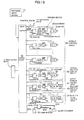
- FIG. 13 is the electric block diagram of a control device in the first embodiment.
- FIG. 14 is the electric block diagram of a control device in the second embodiment.
- FIG. 15 is the electric block diagram of a control device in the third embodiment.
- FIG. 16 is a perspective view of a conventional wire winding apparatus.
- FIG. 17 is a rear perspective view of the apparatus of FIG. 1 .
- FIG. 1 is a perspective view of a wire winding apparatus of the first embodiment according to the present invention
- FIG. 2 is a perspective view for explaining the method of engaging the wire to the terminal of a bobbin in the first embodiment
- FIG. 5 is a section view showing the structure of an embodiment of bobbin installing part
- FIG. 6 is a perspective view of FIG. 5
- FIG. 7 is a section view showing another embodiment of bobbin installing part
- FIG. 9 is a perspective view of FIG. 7, and
- FIG. 13 is the electric block diagram of a control device in the first embodiment.
- a base frame 2 A which has L-shaped section.
- a winding head 25 A for winding up wire is installed in the front side of the base frame 2 A.
- Each of a plurality of spindles 6 having bobbin installing part 7 on its one end side is supported in the winding head 25 A for rotation by the medium of springs and the other end side of the spindle is inserted into the spindle motor 9 A so as to act as the rotation shaft of the motor 9 A.
- a plurality of wire winding parts 3 A are installed in the winding head 25 A.
- Clamps 77 for engaging wires 24 to the bobbin terminals 8 Ab are mounted facing the rear end of the spindle motor 9 on the base frame 2 A.
- a right and a left guide rail 51 , 51 (left rail is not shown for convenience sake), and a receiver plate 10 is mounted for slide in the direction of up and down guided by the guide rails 51 , 51 .
- the receiver plate 10 can be moved up and down in FIG. 1 driven by a motor 53 shown in FIG. 17, for a hole 55 is provided on the face 2 Aa through which a connecting bar 56 is connected to a block 52 underneath which is mounted the motor 53 , and the rotation shaft 53 a , with a guide screw cut on it, of the motor 53 passes through the guide screw hole in the block 52 .
- a frame 12 is mounted for slide in the direction of right-and-left.
- a rotation shaft 21 a on which a guide screw is cut passes through the frame 12 , a pulley 21 is fixed at the end of the rotation shaft 21 a, a motor 19 is mounted on the underside of the receiver plate 10 , a pulley 20 is fixed to the rotation shaft of the motor 19 , and a belt 46 is looped over the pulley 20 and pulley 21 , so the frame is moved toward right-and-left as the motor 19 rotates.
- a motor 13 On the rear side of the frame 12 is mounted a motor 13 , and the height of the base frame 2 A is limited so that the motor 13 does not interfere with the base frame 2 A when the frame moves up and down.
- a slide plate 15 is provided in the frame 12 , guide bars 14 , 14 are fixed on the rear side and bars 16 , 16 on the front side of the slide plate 15 .
- a nozzle fixing member 17 is fixed to the end sides of the bars 16 , 16 in the front outside of the frame 12 .
- the horizontal longitudinal, horizontal lateral, and vertical positions of the nozzles 18 can be set.
- the wires 24 are supplied by way of a wire transit part 14 provided in the rear of the base frame 2 A.
- the wire transit part 14 consists of pillars 22 and tension causing parts 23 for causing tension to be generated in the wires.
- a spool 31 corresponding to each wire is provided, as shown in FIG. 4, in the rear of the base 1 .
- each tension causing part 23 consists of a transit roller 57 , transit arm 54 provided with a transit roller 58 at the tip and supported rotatable about a shaft 56 , and a coil spring for exerting force in the clockwise direction.
- magnetic brake force is applied to the transit roller 57 to exert proper friction thereon.
- the motor 9 A with an encorder 32 is attached to the winding head 25 A, and an end part 6 Aa of the spindle 6 A supported for rotation by bearings 33 , 33 is inserted into the motor 9 A in the center.
- the end part 6 Aa of the spindle 6 A is, for example, shaped to have an oval section, and the oval-shaped part engages with the concave part of the motor side.
- a hole 6 Ab is machined on the right end of the spindle 6 A, the smaller diameter part 34 Ab of a winding jig 34 A is inserted into the hole 6 Ab to be fixed by a set screw 40 .
- a hole 34 Aa is machined in the center of the larger diameter part of the winding jig 34 A, and the rear end side 35 b of a bobbin attaching shaft 35 is inserted into the hole 34 Aa to be fixed by a set screw 40 .
- a slit 35 a is provided in the right end side of the bobbin attaching shaft 35 to cause friction between the shaft 35 and the bobbin 8 A in order to hold the bobbin 8 A on the shaft 35 so that the bobbin attached to the shaft 35 does not rotate and smooth winding is performed.
- a motor 9 A with an encorder 32 A is attached to the winding head 25 B, and an end part 6 Ba of the spindle 6 B supported for rotation by bearings 33 , 33 is inserted into the motor 9 A in the center.
- the end part 6 ba of the spindle 6 B is, for example, shaped to have an oval section, and the oval-shaped part engages with the concave part of the motor side.
- a screw is cut on the right end part 6 Bb of the spindle 6 B, a nut 41 is screwed in and also a winding jig 34 B is screwed in.
- the winding jig 34 B is, as shown in FIG. 8, shaped like a cylinder having inner hollow space 34 Ba.
- Six through holes 34 Bb penetrate the cylinder wall radially as shown in FIG. 8, and in the through holes are inserted ball plungers 43 a, 43 b, and a coil springs 44 .
- Each of the trough holes is shaped so that it is smaller in diameter at the inner hollow space side than at the outer periphery side of the cylindrical winding jig 34 B in order to prevent the dropping of the ball plungers 43 A into the inner hollow space 34 Ba.
- a plunger pusher 38 is put on the outer periphery of the winding jig 34 B slidable in back-and-forth direction(right-and-left direction in FIG. 7 and FIG. 8 ).
- a spring 39 is inserted between the flange part at the rear end of the winding jig 34 B and the rear end face 38 a of the plunger pusher 38 , the plunger pusher 38 is stopped by a nut 51 screwed on the forward end part of the winding jig 34 B, and the spring 39 exerts force on the rear end face 38 a of the plunger pusher 38 in the forward direction.
- the plunger pusher 38 has a cone-shaped cam face 38 b which tapers in the backward direction.
- a passing jig 42 is inserted in the inner hollow space 34 Ba, a groove 42 d is machined on the inserted part of the passing jig.
- the ball plunger 43 a contacts on the bottom and/or inclined side face of the groove 42 d to fix the passing jig 42 concerning the axial direction.
- the passing jig 42 is fixed concerning the circumferential direction by the fitting of the convex part provided on the passing jig with the notch provided in the winding jig 34 B.
- a hole 42 a is machined in the center of the larger diameter part of the passing jig 42 , and rear end part 35 b of the bobbin attaching shaft 35 is inserted into the hole 42 a to be fixed by a set screw 40 .
- the right end part of the bobbin attaching shaft 35 tapers in a point, and a slit is machined to cause friction between the shaft 35 and the bobbin 8 A in order to hold the bobbin 8 A on the shaft 35 so that the bobbin attached to the shaft 35 does not rotate and smooth winding is performed.
- an air cylinder 36 is provided below the bearings 33 of the winding head 25 B, a cylinder shaft 45 protrudes in the forward direction from the air cylinder 36 , and a remover handle 37 is fixed to the end of the cylinder shaft 45 .
- the remover handle 37 has at the forward end an upright wall part 37 a which can engages the flange part 38 a of the plunger pusher 38 . Accordingly, when the cylinder shaft 45 is moved leftward by the operation of the air cylinder 36 , the upright wall part 37 a of the remover handle 37 engages the flange part 38 a of the plunger pusher 38 to move it leftward. When the plunger pusher is moved leftward, the pushing force of the ball plungers 43 a decrease, and the passing jig 42 can be removed from the winding jig 34 B.
- an electric block diagram of the control device of the embodiment will be explained with reference to FIG. 13 .
- an electric control device 62 having a CPU inside it and an interface on each of input and output side, is controlled by the control program of a program input device 61 .
- the electric control device 62 is so configured so that, a spindle control circuit 80 for individually controlling a plurality of spindles is connected with a nozzle position control circuit 81 for controlling the position of nozzles for supplying wire, the spindle control circuit 80 and nozzle position control circuit 81 consists of a plurality of circuits respectively, and these circuits can be controlled in synchronism with each other respectively.
- the spindle control circuit 80 has an individual circuit for each of the individual spindles, each circuit controls the motors 9 of which each motor shaft is part of each spindle, each motor having a directly-coupled encorder 32 .
- the motor 9 is connected to the output terminal of the electric control device 62 by way of a counter 63 , a D/A converter 64 , and an amplifier 65 , starts to rotate by the control pulses of the electric control device 62 , and stops the rotation when the number of the feedback pulses sent forth by the encorder 32 coincides with that of the control pulses inputted.
- the encorder 32 is configured so that it sends forth a datum position pulse when the rotation shaft of the motor 9 comes to a predetermined position in a rotation.
- the electric control device 62 sends forth the control pulses to allow the motor 9 to rotate until the datum position pulse comes in, and when it stops to send forth the control pulses, the spindle is set on the initial rotation position owing to the fact that the motor is automatically stopped by the feedback pulses. With this positioning, the wires 24 are engaged to the terminals of the bobbins 8 , and after that the motors 9 are rotated for winding the wires around the bobbins 8 .
- the nozzle position control circuit 81 is a circuit for controlling the position of the nozzle fixing member 17 shown in FIG. 1 .
- the position of the nozzle fixing member 17 in vertical, right-and-left, and back-and-forth direction, accordingly the positions of the nozzles, is controlled by the individual motor.
- the positions of the nozzles are required to be moved also in maintenance work other than when winding is carried out.
- the nozzle position control circuit 81 is of the same configuration as the spindle control circuit 80 .
- a vertical direction control circuit 82 for controlling the vertical position of the spindles is to control the motor 53 of which the motor shaft is connected to the frame 12 , the motor having a directly-coupled encorder 69 .
- the motor 53 is connected to the output terminal of the electric control device 62 by way of a counter 66 , a D/A converter 67 , and an amplifier 68 , starts to rotate by the control pulse of the electric control device 62 , and stops the rotation when the number of the feedback pulses sent forth by the encorder 69 coincides with the number of the control pulses inputted.
- the encorder 69 is configured so that it sends forth a datum position pulse when the rotation shaft of the motor 53 comes to a predetermined position in a rotation.
- a right-and-left direction control circuit 83 is to control the motor 19 of which the motor shaft is connected to the frame 12 by the medium of belt and pulley, the motor having a directly-coupled encorder 73 .
- the motor 19 is connected to the output terminal of the electric control device 62 by way of a counter 70 , a D/A converter 71 , and an amplifier 72 , starts to rotate by the control pulses of the electric control device 62 , and stops the rotation when the number of the feedback pulse sent forth by the encorder 73 coincides with the number of the control pulses inputted.
- a back-and-forth direction control circuit 95 is to control the motor 13 which is mounted on the frame 12 and of which the motor shaft is connected with the slide plate 15 by the guide screw of the motor shaft, the motor 13 having a directly-coupled encorder 95 .
- the motor 13 is connected to the output terminal of the electric control device 62 by way of a counter 74 , a D/A converter 75 , and an amplifier 76 , starts to rotate by the control pulses of the electric control device 62 , and stops the rotation when the number of the feedback pulses sent forth by the encorder 95 coincides with the number of the control pulses inputted.
- Each of these encorders 69 , 73 , and 95 is configured so that it sends forth a datum position pulse when the rotation shaft of each of the motors 53 , 19 , and 13 comes to a predetermined position in a rotation.
- the electric control device 62 sends forth control pulses to allow each of the motors 53 , 19 , and 13 to rotate until each datum position pulse comes in, and when it stops to send forth the control pulses, the nozzle fixing member 17 is set on the initial position owing to the fact that each of the motors is automatically stopped by the feedback pulses of which the number of pulses coincides with that of the control pulses.
- a signal wire of a magnetic valve 79 for switching the air supplied from an air compressor 59 to the air cylinder 36 through a piping 60 is connected to the output terminal of the electric control device 62 .
- the wire 24 from the spool 31 is stringed over the transit roller 57 and 58 for causing tension by the medium of magnetic braking, and the tip of the wire 24 is allowed to hang down from the nozzle 18 as shown in FIG. 1 .
- an input-output means 85 is manipulated to operate the nozzle position control circuit 81 in the state each bobbin 8 is attached to the bobbin attaching shaft 35 of each spindle.
- the spindle control circuit 80 starts operation in synchronism with the operation start of the nozzle position control circuit 81 to set each bobbin 8 on the predetermined angle position. With this condition, the tip of each wire 24 is pinched in the pinching part 78 of each clamp 77 , then each nozzle 18 turns around the terminal 8 b of each bobbin 8 to engage the wire 24 to the terminal 8 b. Then each wire 24 is cut with a cutter 79 in between the terminal 8 b and pinching part 78 . The remainder of each wire 24 held by each clamp is discharged by opening the pinching part 78 .
- each wire 24 is wound around each bobbin 8 A.
- the distance from the tip of each nozzle 18 to the outer periphery of each wire 24 wound around each bobbin 8 is controlled to be at the predetermined position by the vertical direction control circuit 82 , and the position of each nozzle 18 is controlled by the right-and-left direction control circuit 83 corresponding to each wound layer of wire and by the back-and-forth direction control circuit 84 corresponding to the number of turns.
- the positions of the nozzles 18 are controlled by the vertical direction control circuit 82 , the right-and-left direction control circuit 83 , and back-and-forth direction control circuit 84 , the positions of nozzles from the outer periphery of the winding wires are controlled with good accuracy even when fine wires of diameter of about 0.02 mm are wound around bobbins.
- FIG. 3 is a perspective view of wire winding apparatus of the second embodiment according to the present invention
- FIG. 4 is a perspective view showing the wire supply and positioning mechanism of the second embodiment
- FIG. 14 is the electric block diagram of a control device in the second embodiment.
- the point of difference from the first embodiment is that, unlike the first embodiment in which the position of each nozzle assigned to each spindle is adjusted in the vertical, right-and-left, and back-and-forth direction by three motors, in the second embodiment, vertical and right-and-left direction control circuits are omitted, and a back-and-forth direction control circuit and a back-and-forth direction fine adjusting circuit are provided in the second embodiment.
- a wire transit part 4 explained in FIG. 1 is provided in the rear of a base 1 , and winding heads 25 B(a ⁇ d) are mounted on the base 1 , on each winding head 25 B being mounted a spindle, a spindle motor, and a bobbin which are explained in the explanation of FIG. 1 and shown in FIG. 5 ⁇ FIG. 9 .
- Nozzle control parts 30 (four nozzle control parts in case shown in figure) fixed to pillars 92 provided on winding heads 25 (A ⁇ d) of a wire winding part 3 B constitute wire tip position adjusting parts 5 B.
- a first traverse platform 26 is provided in the nozzle control part 30 a for slide in the longitudinal direction of a guide rail 30 b guided by the same.
- a rotation shaft 28 a connected with the rotation shaft of a first traverse motor 28 mounted on the pillar 92 has a guide screw cut on it, the rotation shaft 28 a passes through a guide screw hole of the first traverse platform 26 , so the platform 26 can be slid in the longitudinal direction of the rotation shaft 28 a as the motor 28 rotates.
- a second traverse platform 27 with a nozzle 18 fixed to it is provided in the frame part 26 a of the first traverse platform 26 for slide in the longitudinal direction of a guide rail 29 b guided by the same.
- a second traverse motor 29 is attached to the frame part of the first traverse platform on the right end face.
- a rotation shaft 29 a connected with the rotation shaft of the second traverse motor 29 has a guide screw of which the pitch is smaller than that of the rotation shaft 28 a cut on it, the rotation shaft 29 a passes through a guide screw hole of the second traverse platform 27 , so the platform 27 can be slid in the longitudinal direction of the rotation shaft 29 a as the motor 29 rotates.
- the nozzle control part 30 a is configured like this, the position of the nozzle in the vertical and right-and-left direction is fixed, and the initial position of the nozzle 18 can be set only in the back-and-forward direction by controlling the motor 28 and 29 .
- the motor 9 A is operated to wind the wire 24 around the bobbin 8 .
- the electric control device 62 is so configured so that, a spindle control circuit 80 for individually controlling a plurality of spindles is connected with a nozzle position control circuit 93 for controlling the position of nozzles for supplying wire, the spindle control circuit 80 and nozzle position control circuit 93 consists of a plurality of circuits respectively, and these circuits can be controlled in synchronism with each other respectively.
- the back-and-forth direction fine adjusting control circuit 91 is to control the motor 90 connected to the second traverse platform 27 and having an encorder 89 fixed to it.
- the motor 90 is connected to the output terminal of the electric control device 62 by way of a counter 86 , a D/A converter 87 , and an amplifier 88 , starts to rotate by the control pulses of the electric control device 62 , and stops the rotation when the number of the feedback pulses sent forth by the encorder 89 coincides with the number of the control pulses inputted.
- These encorders 89 and 94 are configured so that each sends forth a datum position pulse when the rotation shaft of each of the motors 90 and 28 comes to a predetermined position in a rotation.
- the electric control device 62 sends forth control pulses to allow each of the motors 90 and 28 to rotate until each datum position pulse comes in, and when it stops to send forth the control pulse, the nozzle is set on the initial position owing to the fact that each of the motors is automatically stopped by the feedback pulse of which the number of pulses coincides with that of the control pulses.
- the back-and-forth direction control circuit 84 starts operation to set the first traverse platform 26 on the initial position.
- the spindle control circuit 80 starts operation in synchronism with the operation start of the nozzle position control circuit 93 to set each bobbin 8 on the predetermined angle position. With this condition, the tip part of the wire 24 is engaged to the bobbin terminal, that is, the wire is turned around the terminal by hand or magic hand not shown. Then the tip part of the engaged wire is cut near the bobbin terminal.
- the input-output means 85 is manipulated in order to send a fine adjusting pulse from the electric control device 62 to move the second traverse platform back-and-forth to set nozzle position.
- each spindle is movable in a back-and-forth direction, a flier is attached to each spindle, and a bobbin is provided facing each flier in the third embodiment. Therefore, the position of the wire is adjusted by moving a winding head 25 C back-and-forth instead of operating the wire position adjusting part 5 A (FIG. 1 ).
- a wire position adjusting part 5 C comprises winding heads 25 C, motors 28 for moving the winding heads 25 C back-and-forth, and encorders 94 .
- a motor 9 B with an encorder 32 B is attached to the winding head 25 C, the spindle 6 C is supported by bearings 33 , 33 for rotation with its end part 6 Ca inserted into the center of the motor 9 B and encorder 32 B.
- the end part 6 Ca of the spindle 6 C is, for example, shaped to have an oval section, and the oval-shaped part engages with the concave part of the motor side.
- Fliers 46 (Aa, Ab) are attached to the right end part of the spindle 6 C by the medium of a fixing part 48 which is fixed by a set screw 40 .
- the flier 46 Aa is movable in the direction of the straight arrow in FIG. 12 .
- the flier 46 Aa is provided with transit rollers 46 Ac and 46 Ad, and nozzle 46 Ae.
- the wire 24 can be supplied toward the bobbin 8 by way of the transit rollers 46 Ac and 46 Ad, and nozzle 46 Ae.
- the spindle control circuit 80 is the same as that shown in FIG. 13 and explanation is omitted.
- the back-and-forth direction control circuit 96 is to control the motor 28 having an encorder 94 and connected to the flier 46 .
- the motor 28 is connected to the output terminal of the electric control device 62 by way of a counter 74 , a D/A converter 75 , and an amplifier 76 .
- the motor 28 starts rotation by the control pulses from the electric control device 62 , and stops the rotation when the number of the feedback pulses sent forth by the encorder 32 coincides with that of the control pulses inputted.
- a signal wire of a magnetic valve 79 for switching the air supplied from an air compressor 59 to the air cylinder 36 through a piping 60 is connected to the output terminal of the electric control device 62 .
- a input-output means 85 is manipulated to operate the nozzle position control circuit 81 in the state each bobbin 8 is attached to the bobbin attaching shaft 35 of each spindle.
- the tip part of the wire 24 is engaged to the bobbin terminal, that is, the wire is turned around the terminal by hand or magic hand not shown. Then the tip part of the engaged wire is cut near the bobbin terminal.
- a driving source for rotating wind-up tool is provided for each wind-up tool in the first and second invention and because a driving source for rotating a wire supply part which supplies the wire to a stationary winding part is provided for each wire supply part in the third invention, unlike the case a plurality of wind-up tools are driven by a driving source by the medium of a belt.
Landscapes
- Engineering & Computer Science (AREA)
- Power Engineering (AREA)
- Manufacturing & Machinery (AREA)
- Textile Engineering (AREA)
- Coil Winding Methods And Apparatuses (AREA)
- Winding Filamentary Materials (AREA)
- Manufacture Of Motors, Generators (AREA)
Applications Claiming Priority (2)
| Application Number | Priority Date | Filing Date | Title |
|---|---|---|---|
| JP2000219809A JP3638858B2 (ja) | 2000-07-19 | 2000-07-19 | 線材の巻線方法及び装置 |
| JP2000-219809 | 2000-07-19 |
Publications (2)
| Publication Number | Publication Date |
|---|---|
| US20020030134A1 US20020030134A1 (en) | 2002-03-14 |
| US6679449B2 true US6679449B2 (en) | 2004-01-20 |
Family
ID=18714523
Family Applications (1)
| Application Number | Title | Priority Date | Filing Date |
|---|---|---|---|
| US09/907,922 Expired - Lifetime US6679449B2 (en) | 2000-07-19 | 2001-07-19 | Method and apparatus for winding wire |
Country Status (7)
| Country | Link |
|---|---|
| US (1) | US6679449B2 (ja) |
| EP (1) | EP1174889B2 (ja) |
| JP (1) | JP3638858B2 (ja) |
| KR (1) | KR100767230B1 (ja) |
| CN (1) | CN1214413C (ja) |
| DE (1) | DE60139969D1 (ja) |
| TW (1) | TW530314B (ja) |
Cited By (8)
| Publication number | Priority date | Publication date | Assignee | Title |
|---|---|---|---|---|
| US20090108118A1 (en) * | 2006-03-31 | 2009-04-30 | Akihiro Maruyama | Wire Winding Apparatus |
| US20090159736A1 (en) * | 2005-12-26 | 2009-06-25 | Mitsutoshi Asano | Wiring Apparatus |
| CN101667765A (zh) * | 2008-07-10 | 2010-03-10 | 西门子公司 | 用于绕制单层线圈的装置和方法 |
| CN102136366A (zh) * | 2011-01-20 | 2011-07-27 | 珠海安电电子科技有限公司 | 双工位多头绕线机 |
| CN102360934A (zh) * | 2011-08-12 | 2012-02-22 | 云南(炬锋)电焊机有限公司 | 扁线立绕机 |
| CN102117697B (zh) * | 2009-12-31 | 2013-01-02 | 比亚迪股份有限公司 | 一种绕线装置和包含该绕线装置的绕线机 |
| US20140252906A1 (en) * | 2013-03-11 | 2014-09-11 | Regal Beloit America, Inc. | Electrical coil forming apparatus and methods of assembling electrical coils |
| US20160049239A1 (en) * | 2013-04-12 | 2016-02-18 | Nittoku Engineering Co., Ltd. | Coil manufacturing apparatus |
Families Citing this family (28)
| Publication number | Priority date | Publication date | Assignee | Title |
|---|---|---|---|---|
| KR100430760B1 (ko) * | 2001-07-25 | 2004-05-10 | (주)누리 이엔지 | 복수 스핀들 구동형 권선기 제어시스템 및 이를 이용한 제어방법 |
| JP4549754B2 (ja) * | 2004-06-25 | 2010-09-22 | 富士重工業株式会社 | コイル製造方法及びコイル製造装置 |
| JP4875952B2 (ja) * | 2006-09-15 | 2012-02-15 | 株式会社日立産機システム | コイルの巻線方法 |
| US8253524B2 (en) * | 2007-10-04 | 2012-08-28 | Keihin Corporation | Coil winding system and method for fabricating molded coil |
| TWI459421B (zh) * | 2008-12-26 | 2014-11-01 | Delta Electronics Dongguan Co Ltd | 製造一線圈總成之方法及裝置 |
| ITAL20090001A1 (it) * | 2009-02-17 | 2010-08-17 | Cravanzola E Veglio S N C | Apparecchiatura per la realizzazione di bonine eletriche e simili |
| AU2016231607B2 (en) * | 2009-07-02 | 2018-09-13 | C.R. Bard, Inc. | Checkering balloon winding machine |
| US8236223B2 (en) * | 2009-07-02 | 2012-08-07 | C.R. Bard, Inc. | Checker balloon winding machine |
| CN102773382A (zh) * | 2012-07-30 | 2012-11-14 | 林淑琴 | 一种立式盘圆机 |
| CN102784856A (zh) * | 2012-07-30 | 2012-11-21 | 林淑琴 | 一种卧式盘圆机 |
| JP6309732B2 (ja) | 2013-09-30 | 2018-04-11 | 株式会社東芝 | 巻線装置、巻線方法 |
| JP6428771B2 (ja) * | 2014-05-22 | 2018-11-28 | 株式会社村田製作所 | 多線巻線方法及び多線巻線装置 |
| CN104079125B (zh) * | 2014-05-28 | 2016-08-24 | 苏州市圣玛特电机设备制造有限公司 | 一种多工位绕线机 |
| CN104085734B (zh) * | 2014-07-24 | 2017-09-29 | 牙克石市胜利塑料编织包装有限公司 | 圆织麻线分线机和缠绕小麻线团的方法 |
| CN104299724A (zh) * | 2014-09-26 | 2015-01-21 | 安徽蛟龙科技有限公司 | 一种镀锡铜丝镀完锡后的收线装置 |
| CN105761927B (zh) * | 2014-12-15 | 2017-11-07 | 深圳市有钢机电设备有限公司 | 绕线机及绕线方法 |
| CN105129517B (zh) * | 2015-08-11 | 2019-05-28 | 徐州恒辉编织机械有限公司 | 一种小绳缆自动包装成型机 |
| CN105600587A (zh) * | 2015-10-15 | 2016-05-25 | 王波 | 自动绕绳机 |
| JP7058454B2 (ja) * | 2017-09-28 | 2022-04-22 | Nittoku株式会社 | 分割部材の巻線装置及びその巻線方法 |
| CN110419086B (zh) * | 2018-02-28 | 2021-03-12 | 日特有限公司 | 线圈制造装置和线圈制造方法 |
| JP2019153705A (ja) * | 2018-03-05 | 2019-09-12 | 日特エンジニアリング株式会社 | 巻線装置並びにそれを用いた製造設備及び巻線方法並びに完成品の製造方法 |
| CN109850703B (zh) * | 2019-02-27 | 2023-12-01 | 大连萌羽机械有限公司 | 一种飞机发动机卡箍减震垫的绕线加工工装 |
| CN112141815B (zh) * | 2020-10-20 | 2022-06-07 | 湖南腾博复合材料有限公司 | 一种环式结构型调节绕线装置 |
| CN114188789A (zh) * | 2021-12-15 | 2022-03-15 | 天津斯巴克瑞汽车电子股份有限公司 | 高压骨架过渡线自动绕线焊接装置及实现方法 |
| CN114703575A (zh) * | 2021-12-27 | 2022-07-05 | 宜宾恒丰丽雅纺织科技有限公司 | 一种防霉菌的腈纶混纺纱线及其制备工艺 |
| CN114242449B (zh) * | 2022-02-25 | 2022-05-20 | 绵阳聚贤自动化设备有限公司 | 网络滤波器的自动绕脚设备 |
| CN114538208A (zh) * | 2022-03-22 | 2022-05-27 | 郑州铁路职业技术学院 | 一种高铁行车设备故障诊断装置 |
| WO2024023614A1 (en) * | 2022-07-26 | 2024-02-01 | G.D S.P.A. | Method and machine to manufacture windings around multiple supports |
Citations (12)
| Publication number | Priority date | Publication date | Assignee | Title |
|---|---|---|---|---|
| US2401954A (en) * | 1943-02-06 | 1946-06-11 | Western Electric Co | Testing apparatus |
| DE3049406A1 (de) | 1980-12-23 | 1982-07-29 | Siemens AG, 1000 Berlin und 8000 München | Verfahren zum anwickeln der drahtenden gewickelter elektrischer spulen an aufnahmestiften |
| EP0143319A1 (fr) | 1983-11-02 | 1985-06-05 | Sarcem Sa | Dispositif électromécanique de bobinage avec fixation aux extrémités |
| DE3527311A1 (de) | 1985-07-26 | 1987-01-29 | Siemens Ag | Verfahren zum herstellen einer elektrischen spule mit mehreren wicklungen |
| JPH0467608A (ja) * | 1990-07-09 | 1992-03-03 | Matsushita Electric Ind Co Ltd | 巻線方法およびその巻線装置 |
| JPH05326312A (ja) * | 1992-05-15 | 1993-12-10 | Nittoku Eng Co Ltd | 自動巻線機 |
| US5314129A (en) * | 1991-04-24 | 1994-05-24 | Tekma Kinomat S.R.L. | Coil winder with spindlehead movable in a horizontal plane |
| US5538196A (en) * | 1994-06-06 | 1996-07-23 | Bachi, L.P. | Spindle coil winding machine |
| US5582357A (en) * | 1993-11-08 | 1996-12-10 | Sony Corporation | Coil winding apparatus |
| US5806781A (en) * | 1994-04-21 | 1998-09-15 | Sony Corporation | Winding apparatus and method |
| JPH1127909A (ja) | 1997-07-02 | 1999-01-29 | Nittoku Eng Co Ltd | 巻線機および巻線方法 |
| US6102324A (en) * | 1998-06-08 | 2000-08-15 | Ats Automation Tooling Systems Inc. | Coil hitching device |
Family Cites Families (5)
| Publication number | Priority date | Publication date | Assignee | Title |
|---|---|---|---|---|
| JPS5910162A (ja) † | 1982-07-05 | 1984-01-19 | Mitsubishi Electric Corp | ブラシレス化直流モ−タ |
| US4807430A (en) † | 1987-10-22 | 1989-02-28 | Walker Magnetics Group, Inc. | Thread wrapping apparatus |
| US5202610A (en) † | 1991-08-30 | 1993-04-13 | Platt Saco Lowell | Method and apparatus for yarn end-down detection in a textile yarn winding machine |
| DE69932961T2 (de) † | 1998-03-13 | 2007-05-10 | Murata Kikai K.K. | Textilmaschine mit Einzelspindelantrieb wobei die Spindelantriebe in modularen Einheiten aufgeteilt sind. |
| DE69914283T2 (de) † | 1998-11-05 | 2004-10-21 | Toyota Jidoshokki Kariya Kk | Ringspinnmaschine mit Individuellen Spindelantrieben |
-
2000
- 2000-07-19 JP JP2000219809A patent/JP3638858B2/ja not_active Expired - Lifetime
-
2001
- 2001-07-10 EP EP01116851.5A patent/EP1174889B2/en not_active Expired - Lifetime
- 2001-07-10 DE DE60139969T patent/DE60139969D1/de not_active Expired - Lifetime
- 2001-07-18 KR KR1020010043226A patent/KR100767230B1/ko active IP Right Grant
- 2001-07-19 US US09/907,922 patent/US6679449B2/en not_active Expired - Lifetime
- 2001-07-19 CN CNB011229241A patent/CN1214413C/zh not_active Expired - Lifetime
- 2001-07-19 TW TW090117713A patent/TW530314B/zh not_active IP Right Cessation
Patent Citations (13)
| Publication number | Priority date | Publication date | Assignee | Title |
|---|---|---|---|---|
| US2401954A (en) * | 1943-02-06 | 1946-06-11 | Western Electric Co | Testing apparatus |
| DE3049406A1 (de) | 1980-12-23 | 1982-07-29 | Siemens AG, 1000 Berlin und 8000 München | Verfahren zum anwickeln der drahtenden gewickelter elektrischer spulen an aufnahmestiften |
| EP0143319A1 (fr) | 1983-11-02 | 1985-06-05 | Sarcem Sa | Dispositif électromécanique de bobinage avec fixation aux extrémités |
| DE3527311A1 (de) | 1985-07-26 | 1987-01-29 | Siemens Ag | Verfahren zum herstellen einer elektrischen spule mit mehreren wicklungen |
| JPH0467608A (ja) * | 1990-07-09 | 1992-03-03 | Matsushita Electric Ind Co Ltd | 巻線方法およびその巻線装置 |
| US5314129A (en) * | 1991-04-24 | 1994-05-24 | Tekma Kinomat S.R.L. | Coil winder with spindlehead movable in a horizontal plane |
| JPH05326312A (ja) * | 1992-05-15 | 1993-12-10 | Nittoku Eng Co Ltd | 自動巻線機 |
| US5397070A (en) * | 1992-05-15 | 1995-03-14 | Nittoku Engineering Kabushiki Kaisha | Automatic coil winder |
| US5582357A (en) * | 1993-11-08 | 1996-12-10 | Sony Corporation | Coil winding apparatus |
| US5806781A (en) * | 1994-04-21 | 1998-09-15 | Sony Corporation | Winding apparatus and method |
| US5538196A (en) * | 1994-06-06 | 1996-07-23 | Bachi, L.P. | Spindle coil winding machine |
| JPH1127909A (ja) | 1997-07-02 | 1999-01-29 | Nittoku Eng Co Ltd | 巻線機および巻線方法 |
| US6102324A (en) * | 1998-06-08 | 2000-08-15 | Ats Automation Tooling Systems Inc. | Coil hitching device |
Cited By (15)
| Publication number | Priority date | Publication date | Assignee | Title |
|---|---|---|---|---|
| US20090159736A1 (en) * | 2005-12-26 | 2009-06-25 | Mitsutoshi Asano | Wiring Apparatus |
| US7614579B2 (en) * | 2005-12-26 | 2009-11-10 | Toyota Jidosha Kabushiki Kaisha | Wiring apparatus |
| US20090108118A1 (en) * | 2006-03-31 | 2009-04-30 | Akihiro Maruyama | Wire Winding Apparatus |
| US7775474B2 (en) * | 2006-03-31 | 2010-08-17 | Taga Manufacturing Co., Ltd. | Wire winding apparatus |
| CN101667765A (zh) * | 2008-07-10 | 2010-03-10 | 西门子公司 | 用于绕制单层线圈的装置和方法 |
| CN101667765B (zh) * | 2008-07-10 | 2015-04-29 | 西门子公司 | 用于绕制单层线圈的装置和方法 |
| CN102117697B (zh) * | 2009-12-31 | 2013-01-02 | 比亚迪股份有限公司 | 一种绕线装置和包含该绕线装置的绕线机 |
| CN102136366B (zh) * | 2011-01-20 | 2012-10-10 | 珠海恒阳科技有限公司 | 双工位多头绕线机 |
| CN102136366A (zh) * | 2011-01-20 | 2011-07-27 | 珠海安电电子科技有限公司 | 双工位多头绕线机 |
| CN102360934B (zh) * | 2011-08-12 | 2012-12-05 | 云南(炬锋)电焊机有限公司 | 扁线立绕机 |
| CN102360934A (zh) * | 2011-08-12 | 2012-02-22 | 云南(炬锋)电焊机有限公司 | 扁线立绕机 |
| US20140252906A1 (en) * | 2013-03-11 | 2014-09-11 | Regal Beloit America, Inc. | Electrical coil forming apparatus and methods of assembling electrical coils |
| US9230735B2 (en) * | 2013-03-11 | 2016-01-05 | Regal Beloit America, Inc. | Electrical coil forming apparatus and methods of assembling electrical coils |
| US20160049239A1 (en) * | 2013-04-12 | 2016-02-18 | Nittoku Engineering Co., Ltd. | Coil manufacturing apparatus |
| US9704645B2 (en) * | 2013-04-12 | 2017-07-11 | Nittoku Engineering Co., Ltd. | Coil manufacturing apparatus |
Also Published As
| Publication number | Publication date |
|---|---|
| KR100767230B1 (ko) | 2007-10-16 |
| DE60139969D1 (de) | 2009-11-05 |
| EP1174889B1 (en) | 2009-09-23 |
| EP1174889A2 (en) | 2002-01-23 |
| TW530314B (en) | 2003-05-01 |
| CN1335630A (zh) | 2002-02-13 |
| CN1214413C (zh) | 2005-08-10 |
| US20020030134A1 (en) | 2002-03-14 |
| EP1174889B2 (en) | 2014-12-10 |
| EP1174889A3 (en) | 2002-01-30 |
| JP3638858B2 (ja) | 2005-04-13 |
| JP2002043157A (ja) | 2002-02-08 |
| KR20020008071A (ko) | 2002-01-29 |
Similar Documents
| Publication | Publication Date | Title |
|---|---|---|
| US6679449B2 (en) | Method and apparatus for winding wire | |
| US6341744B1 (en) | Coil winding apparatus and winding method | |
| JP5196913B2 (ja) | スピンドル巻線装置 | |
| US9033271B2 (en) | Wire winding apparatus and wire winding method | |
| CN110316617B (zh) | 无托盘可变径多连杆绕线系统 | |
| JP2000158390A (ja) | プリント基板加工機 | |
| US11239029B2 (en) | Winding apparatus and winding method using same | |
| JPH04226840A (ja) | スパーク腐食式切断機の電極をホイールの周りに一巡させる装置 | |
| CN1950283B (zh) | 用于连续卷绕多根丝线的方法和设备 | |
| EP3383780B1 (en) | A method to position spindle precisely in turret type automatic winder | |
| CN111975143B (zh) | 电线放电加工装置及电线放电加工方法 | |
| JP3566753B2 (ja) | テンション装置 | |
| JP4612673B2 (ja) | 巻取り装置 | |
| JP2002184640A (ja) | 巻線装置および巻線方法 | |
| JPH03111377A (ja) | 自動ワインダ | |
| KR100249341B1 (ko) | 선재의 자동정렬권취방법 및 그 장치 | |
| CN111788648B (zh) | 使用绕线装置的制造设备、以及完成品的制造方法 | |
| CN113976768B (zh) | 一种微细缠簧绕制机 | |
| JP4088853B2 (ja) | 解舒装置 | |
| JPH0146425B2 (ja) | ||
| JP2858448B2 (ja) | 線材整列巻き方法、及びその装置 | |
| JPH07137933A (ja) | 糸条類のスプール巻き方法及び装置 | |
| JP4001769B2 (ja) | スピンドル旋回巻線機 | |
| JPS60186316A (ja) | タツプ盤 | |
| JP2519558B2 (ja) | テ―ピング用粘着テ―プの繰出し装置 |
Legal Events
| Date | Code | Title | Description |
|---|---|---|---|
| AS | Assignment |
Owner name: NITTOKU ENGINEERING CO., LTD., JAPAN Free format text: ASSIGNMENT OF ASSIGNORS INTEREST;ASSIGNOR:SUGIUCHI, YOSUKE;REEL/FRAME:012327/0728 Effective date: 20011009 |
|
| STCF | Information on status: patent grant |
Free format text: PATENTED CASE |
|
| FPAY | Fee payment |
Year of fee payment: 4 |
|
| FEPP | Fee payment procedure |
Free format text: PAYOR NUMBER ASSIGNED (ORIGINAL EVENT CODE: ASPN); ENTITY STATUS OF PATENT OWNER: LARGE ENTITY |
|
| FPAY | Fee payment |
Year of fee payment: 8 |
|
| FPAY | Fee payment |
Year of fee payment: 12 |