US10047844B2 - Dynamic damper device - Google Patents
Dynamic damper device Download PDFInfo
- Publication number
- US10047844B2 US10047844B2 US14/759,372 US201414759372A US10047844B2 US 10047844 B2 US10047844 B2 US 10047844B2 US 201414759372 A US201414759372 A US 201414759372A US 10047844 B2 US10047844 B2 US 10047844B2
- Authority
- US
- United States
- Prior art keywords
- rotational speed
- inertia ring
- slider
- output
- lock
- Prior art date
- Legal status (The legal status is an assumption and is not a legal conclusion. Google has not performed a legal analysis and makes no representation as to the accuracy of the status listed.)
- Active, expires
Links
Images


Classifications
-
- F—MECHANICAL ENGINEERING; LIGHTING; HEATING; WEAPONS; BLASTING
- F16—ENGINEERING ELEMENTS AND UNITS; GENERAL MEASURES FOR PRODUCING AND MAINTAINING EFFECTIVE FUNCTIONING OF MACHINES OR INSTALLATIONS; THERMAL INSULATION IN GENERAL
- F16H—GEARING
- F16H45/00—Combinations of fluid gearings for conveying rotary motion with couplings or clutches
- F16H45/02—Combinations of fluid gearings for conveying rotary motion with couplings or clutches with mechanical clutches for bridging a fluid gearing of the hydrokinetic type
-
- F—MECHANICAL ENGINEERING; LIGHTING; HEATING; WEAPONS; BLASTING
- F16—ENGINEERING ELEMENTS AND UNITS; GENERAL MEASURES FOR PRODUCING AND MAINTAINING EFFECTIVE FUNCTIONING OF MACHINES OR INSTALLATIONS; THERMAL INSULATION IN GENERAL
- F16F—SPRINGS; SHOCK-ABSORBERS; MEANS FOR DAMPING VIBRATION
- F16F15/00—Suppression of vibrations in systems; Means or arrangements for avoiding or reducing out-of-balance forces, e.g. due to motion
- F16F15/10—Suppression of vibrations in rotating systems by making use of members moving with the system
- F16F15/12—Suppression of vibrations in rotating systems by making use of members moving with the system using elastic members or friction-damping members, e.g. between a rotating shaft and a gyratory mass mounted thereon
- F16F15/129—Suppression of vibrations in rotating systems by making use of members moving with the system using elastic members or friction-damping members, e.g. between a rotating shaft and a gyratory mass mounted thereon characterised by friction-damping means
-
- F—MECHANICAL ENGINEERING; LIGHTING; HEATING; WEAPONS; BLASTING
- F16—ENGINEERING ELEMENTS AND UNITS; GENERAL MEASURES FOR PRODUCING AND MAINTAINING EFFECTIVE FUNCTIONING OF MACHINES OR INSTALLATIONS; THERMAL INSULATION IN GENERAL
- F16F—SPRINGS; SHOCK-ABSORBERS; MEANS FOR DAMPING VIBRATION
- F16F15/00—Suppression of vibrations in systems; Means or arrangements for avoiding or reducing out-of-balance forces, e.g. due to motion
- F16F15/10—Suppression of vibrations in rotating systems by making use of members moving with the system
- F16F15/14—Suppression of vibrations in rotating systems by making use of members moving with the system using masses freely rotating with the system, i.e. uninvolved in transmitting driveline torque, e.g. rotative dynamic dampers
- F16F15/1407—Suppression of vibrations in rotating systems by making use of members moving with the system using masses freely rotating with the system, i.e. uninvolved in transmitting driveline torque, e.g. rotative dynamic dampers the rotation being limited with respect to the driving means
- F16F15/1414—Masses driven by elastic elements
- F16F15/1421—Metallic springs, e.g. coil or spiral springs
-
- F—MECHANICAL ENGINEERING; LIGHTING; HEATING; WEAPONS; BLASTING
- F16—ENGINEERING ELEMENTS AND UNITS; GENERAL MEASURES FOR PRODUCING AND MAINTAINING EFFECTIVE FUNCTIONING OF MACHINES OR INSTALLATIONS; THERMAL INSULATION IN GENERAL
- F16H—GEARING
- F16H45/00—Combinations of fluid gearings for conveying rotary motion with couplings or clutches
- F16H45/02—Combinations of fluid gearings for conveying rotary motion with couplings or clutches with mechanical clutches for bridging a fluid gearing of the hydrokinetic type
- F16H2045/0205—Combinations of fluid gearings for conveying rotary motion with couplings or clutches with mechanical clutches for bridging a fluid gearing of the hydrokinetic type two chamber system, i.e. without a separated, closed chamber specially adapted for actuating a lock-up clutch
-
- F—MECHANICAL ENGINEERING; LIGHTING; HEATING; WEAPONS; BLASTING
- F16—ENGINEERING ELEMENTS AND UNITS; GENERAL MEASURES FOR PRODUCING AND MAINTAINING EFFECTIVE FUNCTIONING OF MACHINES OR INSTALLATIONS; THERMAL INSULATION IN GENERAL
- F16H—GEARING
- F16H45/00—Combinations of fluid gearings for conveying rotary motion with couplings or clutches
- F16H45/02—Combinations of fluid gearings for conveying rotary motion with couplings or clutches with mechanical clutches for bridging a fluid gearing of the hydrokinetic type
- F16H2045/0221—Combinations of fluid gearings for conveying rotary motion with couplings or clutches with mechanical clutches for bridging a fluid gearing of the hydrokinetic type with damping means
- F16H2045/0226—Combinations of fluid gearings for conveying rotary motion with couplings or clutches with mechanical clutches for bridging a fluid gearing of the hydrokinetic type with damping means comprising two or more vibration dampers
-
- F—MECHANICAL ENGINEERING; LIGHTING; HEATING; WEAPONS; BLASTING
- F16—ENGINEERING ELEMENTS AND UNITS; GENERAL MEASURES FOR PRODUCING AND MAINTAINING EFFECTIVE FUNCTIONING OF MACHINES OR INSTALLATIONS; THERMAL INSULATION IN GENERAL
- F16H—GEARING
- F16H45/00—Combinations of fluid gearings for conveying rotary motion with couplings or clutches
- F16H45/02—Combinations of fluid gearings for conveying rotary motion with couplings or clutches with mechanical clutches for bridging a fluid gearing of the hydrokinetic type
- F16H2045/0273—Combinations of fluid gearings for conveying rotary motion with couplings or clutches with mechanical clutches for bridging a fluid gearing of the hydrokinetic type characterised by the type of the friction surface of the lock-up clutch
- F16H2045/0294—Single disk type lock-up clutch, i.e. using a single disc engaged between friction members
Definitions
- the present invention relates to a dynamic damper device, particularly to a dynamic damper device mounted to an output-side member of a torque converter.
- a torque converter is equipped with a lock-up device to reduce fuel consumption.
- the lock-up device is disposed between a front cover and a turbine, and is configured to mechanically couple the front cover and the turbine to directly transmit a torque therebetween.
- the lock-up device includes a piston and a damper mechanism.
- the piston is pressed onto the front cover by the action of hydraulic pressure, and a torque is transmitted to the piston from the front cover.
- the damper mechanism includes a plurality of torsion springs, and the piston and an output-side member coupled to the turbine are elastically coupled by the plural torsion springs.
- the torque transmitted to the piston is transmitted to the output-side member through the plural torsion springs, and is further transmitted to the turbine.
- Japanese Laid-open Patent Application Publication No. 2009-293671 describes a lock-up device in which an inertia member is mounted to the output-side member to inhibit variation in engine rotation.
- the inertia member is mounted to the output member fixed to the turbine to be rotatable relative thereto.
- torsion springs are mounted as elastic members between the output-side member and the inertia member.
- the inertia member is coupled to the output member through the torsion springs. Therefore, the inertia member and the torsion springs function as a dynamic damper, and these components attenuate variation in rotational speed of the output-side member (turbine).
- the torsion springs composing a part of the dynamic damper device, are disposed between the piston and the turbine, and as described above, an annular plate member is elastically coupled to the output member through the torsion springs. Furthermore, an inertia ring is fixed to the outer peripheral part of the annular plate.
- a dynamic damper device is a device mounted to an output-side member of a torque converter, and includes a rotary member, an inertia ring and a plurality of elastic members.
- the rotary member is fixed to the output-side member and is configured to be rotated.
- the inertia ring has accommodation parts along a circumferential direction and is disposed to be rotatable relative to the rotary member.
- the plural elastic members are disposed in the accommodation parts to elastically couple the rotary member and the inertia ring in a rotational direction.
- the rotary member and the inertia ring are elastically coupled by the plural elastic members, and a variation in rotational speed of the rotary member is inhibited by the inertia ring.
- the inertia ring has the accommodation parts, and the plural elastic members are disposed in the accommodation parts.
- the plural elastic members are herein disposed and accommodated in the accommodation parts of the inertia ring. Hence, a space occupied by the dynamic damper device can be reduced in comparison with a well-known dynamic damper device. Furthermore, the torsion springs are enabled to serve a function of inertia. Hence, an increase in weight of the entire torque converter can be inhibited, and simultaneously, a variation in rotational speed can be effectively inhibited.
- the dynamic damper device preferably includes a hysteresis torque generating mechanism that is disposed in the accommodation parts of the inertia ring and is configured to generate a first hysteresis torque in a low rotational speed range and generate a second hysteresis torque greater than the first hysteresis torque in middle to high rotational speed ranges.
- a hysteresis torque generating mechanism that is disposed in the accommodation parts of the inertia ring and is configured to generate a first hysteresis torque in a low rotational speed range and generate a second hysteresis torque greater than the first hysteresis torque in middle to high rotational speed ranges.
- a lock-up rotational speed a rotational speed at which the front cover and the turbine are coupled
- the engine rotational speed widely varies in a range that the engine rotational speed is low.
- the output-side rotational speed inevitably varies more widely.
- a lock-up device having an inertia member as described in Japanese Laid-open Patent Application Publication No. 2009-293671, a variation in rotation can be inhibited even when the lock-up rotational speed is set to be, for instance, roughly 1200 rpm.
- the lock-up device described in Japanese Laid-open Patent Application Publication No. 2009-293671 is equipped with a hysteresis torque generating mechanism, but variation in output-side rotational speed cannot be inhibited over wide rotational speed ranges.
- an aspect of the present invention is to increase frictional resistance between the rotary member and the inertia member, i.e., hysteresis torque, in accordance with increase in rotational speed. Therefore, a variation in rotational speed on the output side can be inhibited over wide rotational speed ranges. Consequently, with attachment of the dynamic damper device to the lock-up device, a variation in rotational speed can be inhibited over wide rotational speed ranges even when the lock-up rotational speed is set low.
- the hysteresis torque generating mechanism is preferably configured to increase friction between the rotary member and the inertia ring in accordance with an increase in rotational speed to gradually reduce a relative torsion angle between the rotary member and the inertia ring.
- hysteresis torque generating mechanism friction between the rotary member and the inertia ring, i.e., hysteresis torque, gradually increases in accordance with an increase in rotational speed, and accordingly, a relative torsion angle between the both members gradually decreases. Therefore, it is possible to inhibit occurrence of shock attributed to sharp variation in friction between both members and inhibit production of abnormal sound.
- the hysteresis torque generating mechanism includes a slider and a contact member.
- the slider is configured to be rotated together with the inertia ring, is radially movable with respect to the inertia ring, and has a slide surface extending in the rotational direction.
- the contact member is configured to be rotated together with the rotary member, and preferably, movement thereof is restricted as follows.
- the contact member is configured to contact the slide surface of the slider such that a range of a torsion angle relative to the inertia ring is restricted to a first angular range.
- the contact member is configured to contact the slide surface of the slider such that the range of the torsion angle relative to the inertia ring is restricted to a second angular range narrower than the first angular range.
- the contact member is configured to make contact with the slide surface of the slider such that torsion relative to the inertia ring is prevented.
- the slider preferably has a lock part to which the contact member is fitted and that is formed on a middle part of the slide surface in the rotational direction.
- the contact member When the rotational speed reaches the high rotational speed range and the relative torsion angular range between the rotary member and the inertia ring is narrowed, the contact member is finally configured to be fitted to the lock part of the slider, and thus, relative rotation between the both members is prevented. Put differently, the hysteresis torque becomes infinite.
- the accommodation parts of the inertia ring is preferably opened to one side in an axial direction.
- the rotary member is preferably fixed at an inner peripheral part thereof to a turbine of the torque converter.
- the dynamic damper device preferably further includes a side plate that is fixed to a radially intermediate part of the rotary member and supports the inertia ring in a rotatable state.
- the space occupied by the dynamic damper device can be reduced in the axial direction, and in addition, an increase in weight of the entire torque converter can be inhibited and simultaneously a variation in rotational speed can be effectively inhibited.
- FIG. 1 is a cross-sectional view of a construction of a torque converter equipped with a dynamic damper device according to a first exemplary embodiment of the present invention.
- FIG. 2 is a diagram of a lock-up device extracted from FIG. 1 .
- FIG. 3 is a front view of the dynamic damper device in FIG. 1 .
- FIG. 4 is a front view of a damper plate composing a part of the dynamic damper device.
- FIG. 5A is a cross-sectional view of the damper plate of FIG. 4 taken along line O-A.
- FIG. 5B is a cross-sectional view of the damper plate of FIG. 4 taken along line O-B.
- FIG. 5C is a cross-sectional view of the damper plate of FIG. 4 taken along line O-C.
- FIG. 6 is a front view of an inertia ring composing a part of the dynamic damper device.
- FIG. 7 is a cross-sectional view of the inertia ring of FIG. 6 taken along line O-A.
- FIG. 7B is a cross-sectional view of the inertia ring of FIG. 6 taken along line O-B.
- FIG. 7C is a cross-sectional view of the inertia ring of FIG. 6 taken along line O-C.
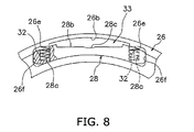
- FIG. 8 is a partial enlarged view of the dynamic damper device of FIG. 3 .
- FIG. 9 is a characteristic diagram of engine rotational speed and variation in rotational speed.
- FIG. 10A is a diagram for explaining actions of a hysteresis torque generating mechanism in which a slider is in a normal condition.
- FIG. 10B is a diagram for explaining actions of a hysteresis torque generating mechanism in which a slider is in an attenuated condition.
- FIG. 10C is a diagram for explaining actions of a hysteresis torque generating mechanism in which a slider is in a locked condition.
- FIG. 1 shows a torque converter according to an exemplary embodiment of the present invention.
- an engine is disposed on the left side, whereas a transmission is disposed on the right side.
- a line O-O depicted in FIG. 1 indicates a rotational axis of the torque converter.
- a torque converter 1 is a device for transmitting a power from a crankshaft of the engine to an input shaft of the transmission, and mainly includes a front cover 2 to which the power is inputted, an impeller 3 , a turbine 4 , a stator 5 , a lock-up device 6 and a dynamic damper device 7 .
- the outer peripheral part of the front cover 2 and that of the impeller 3 are welded to each other, and a fluid chamber is formed by the front cover 2 and the impeller 3 .
- the turbine 4 is disposed within the fluid chamber to be opposed to the impeller 3 .
- the turbine 4 includes a turbine shell 8 , a plurality of turbine blades 9 fixed to the inside of the turbine shell 8 , and a turbine hub 10 fixed to the inner peripheral part of the turbine shell 8 .
- the turbine hub 10 has a tubular part 10 a axially extending and a disc-shaped flange 10 b extending radially outward from the tubular part 10 a .
- the inner peripheral part of the turbine shell 8 is fixed to the outer peripheral part of the flange 10 b by rivets 11 .
- the turbine hub 10 has a spline hole 10 c in the inner peripheral part thereof. Moreover, the input shaft of the transmission (not shown in the drawings) is coupled to the spline hole 10 c .
- the stator 5 is a mechanism for regulating the flow of operating oil from the turbine 4 to the impeller 3 , and is disposed between the inner peripheral part of the impeller 3 and that of the turbine 4 .
- the lock-up device 6 is disposed between the front cover 2 and the turbine 4 .
- the lock-up device 6 includes a piston 13 and a damper mechanism 14 .
- the piston 13 is an annular disc member, and has a disc part 13 a , an inner peripheral tubular part 13 b and an outer peripheral tubular part 13 c .
- the disc part 13 a is disposed in opposition to the front cover 2 , and has a friction member 13 d that is mounted to the outer peripheral part thereof to make frictional contact with the front cover 2 .
- the inner peripheral tubular part 13 b is disposed on the inner peripheral end of the disc part 13 a so as to protrude toward the transmission. Furthermore, the inner peripheral tubular part 13 b is supported by the outer peripheral surface of the tubular part 10 a of the turbine hub 10 to be axially movable and rotatable relative thereto.
- the outer peripheral tubular part 13 c is disposed on the outer peripheral end of the disc part 13 a to protrude toward the transmission, and has a plurality of grooves 13 e having a predetermined axial length.
- FIG. 2 shows the damper mechanism 14 extracted from the entire construction.
- the damper mechanism 14 includes a pair of retaining plates 15 and 16 , an output flange 17 , a plurality of outer peripheral side torsion springs 18 and a plurality of inner peripheral side torsion springs 19 .
- the paired-off retaining plates 15 and 16 are annularly formed disc members, and are disposed so as to be axially opposed at an interval. Both of the retaining plates 15 and 16 have roughly the same shape, and each of them has a plurality of spring accommodation parts 15 a , 16 a located in the outer peripheral part thereof and a plurality of spring accommodation parts 15 b , 16 b located in the inner peripheral part thereof. Additionally, the outer peripheral parts of both plates 15 and 16 are fixed by rivets 20 . Furthermore, each of the plates 15 and 16 has a plurality of teeth 15 c , 16 c on the outer peripheral end thereof, and the teeth 15 c , 16 c are engaged with the grooves 13 e of the piston 13 . With the construction, the damper mechanism 14 is configured to be non-rotatable relatively to the piston 13 and be axially movable.
- the output flange 17 is disposed to be interposed between the paired-off retaining plates 15 and 16 .
- the output flange 17 has cutouts 17 a for spring accommodation in the outer peripheral part thereof, and has openings 17 b for spring accommodation in the inner peripheral part thereof.
- An inner peripheral end 17 c of the output flange 17 is fixed to the flange 10 b of the turbine hub 10 by the rivets 11 .
- the outer peripheral side torsion springs 18 are disposed in the outer peripheral side cutouts 17 a of the output flange 17 , and are supported by the outer peripheral side spring accommodation parts 15 a and 16 a of the paired-off retaining plates 15 and 16 .
- the inner peripheral side torsion springs 19 are disposed in the inner peripheral side openings 17 b of the output flange 17 , and are supported by the inner peripheral side spring accommodation parts 15 b and 16 b of the paired-off retaining plates 15 and 16 .
- the dynamic damper device 7 includes a damper plate 25 (a rotary member), an inertia ring 26 , a plurality of torsion springs 27 , a plurality of sliders 28 , a side plate 29 and a plurality of springs 32 .
- FIG. 3 is a front view of the dynamic damper device 7 .
- a hysteresis torque generating mechanism 33 is composed of part of the damper plate 25 , the plurality of sliders 28 and the plurality of springs 32 , and detailed explanation thereof will be described below.
- FIG. 4 shows a partial front view of the damper plate 25 .
- FIGS. 5A to 5C show cross-sections of the damper plate 25 of FIG. 4 respectively taken along lines O-A, O-B and O-C.
- the damper plate 25 is an annularly formed disc member, and as shown in FIG. 1 , the inner peripheral end thereof is welded to the turbine shell 8 . Furthermore, the damper plate 25 has a plurality of rivet holes 25 a in the radially intermediate part thereof, and has a plurality of pawls 25 b (contact members) and a plurality of engaging parts 25 c on the outer peripheral end thereof. As shown in FIG.
- the pawls 25 b are formed by bending the outer peripheral end of the damper plate 25 toward the transmission. As shown in FIG. 5A , the engaging parts 25 c are formed to be axially displaced toward the transmission than the other part. The pawls 25 b and the engaging parts 25 c are circumferentially disposed in alternate arrangement.
- FIG. 6 shows a partial front view of the inertia ring 26 .
- FIGS. 7A ) to 7 C show cross-sections of the inertia ring 26 of FIG. 6 respectively taken along lines O-A, O-B and O-C.
- the inertia ring 26 is disposed to be rotatable relatively to the damper plate 25 .
- the inertia ring 26 is an annular member, and has a plurality of spring accommodation parts (exemplary accommodation parts) 26 a and a plurality of slider accommodation parts (exemplary accommodation parts) 26 b , both types of which are circumferentially aligned at predetermined intervals.
- the respective accommodation parts 26 a and 26 b are recessed parts formed to be axially opened toward the engine and recessed toward the transmission.
- Each of the plural slider accommodation parts 26 b is disposed to be circumferentially interposed between two of the spring accommodation parts 26 a.
- a plurality of protruding parts 26 c are formed on the outer peripheral end of the inertia ring 26 such that each continues over a region corresponding to one slider accommodation part 26 b and part of two spring accommodation parts 26 a adjacent to the slider accommodation part 26 b .
- the protruding parts 26 c protrude axially toward the engine.
- a restriction part 26 d is formed on the inner peripheral end of the inertia ring 26 to protrude to the inner peripheral side.
- the side plate 29 makes contact with the restriction part 26 d from the transmission side, and axial movement of the inertia ring 26 is thereby restricted. It should be noted that as shown in FIG. 1 , the inner peripheral part of the side plate 29 is fixed to the damper plate 25 by rivets 30 .
- the plurality of torsion springs 27 are accommodated in the spring accommodation parts 26 a of the inertia ring 26 . Additionally, ends of the torsion springs 27 are engaged with both ends of each engaging part 25 c of the damper plate 25 . This results in a construction that the damper plate 25 and the inertia ring 26 are elastically coupled in the rotational direction by the torsion springs 27 .
- the sliders 28 are circumferentially elongated members, and are accommodated in the slider accommodation parts 26 b of the inertia ring 26 to be radially movable.
- FIG. 8 shows the slider accommodation part 26 b of the inertia ring 26 and the slider 28 , which are extracted from the entire construction.
- the slider accommodation part 26 b has spring receiving parts 26 e on both circumferential ends thereof. Additionally, both circumferential end walls of the slider accommodation part 26 b function as guide parts 26 f.
- the slider 28 has spring accommodation parts 28 a that are formed radially inward in both circumferential ends thereof. Moreover, a spring 32 is accommodated in each spring accommodation part 28 a to urge the slider 28 to the inner peripheral side. Both lengthwise ends of the slider 28 slidably contact the guide parts 26 f of the slider accommodation part 26 b . Furthermore, an outer peripheral surface 28 b of the slider 28 curves to be recessed inward. Additionally, a lock part 28 c , to which the pawl 25 b of the damper plate 25 is fitted, is formed on the circumferentially middle part of the outer peripheral surface 28 b.
- the pawls 25 b of the damper plate 25 , the sliders 28 and the springs 32 compose the hysteresis torque generating mechanism 33 that is configured to generate a variable hysteresis torque between the damper plate 25 and the inertia ring 26 .
- the inertia ring 26 , the torsion springs 27 , the sliders 28 and the springs 32 function as an inertia member.
- the lock-up device 6 When the rotational speed of the input shaft reaches a predetermined rotational speed, the lock-up device 6 is turned on, and a power is mechanically transmitted from the front cover 2 to the turbine hub 10 through the lock-up device 6 .
- the piston 13 when the piston 13 is moved toward the engine due to variation in hydraulic pressure and the friction member 13 d of the piston 13 is pressed onto the front cover 2 , the piston 13 is unitarily rotated with the front cover 2 .
- the paired-off retaining plates 15 and 16 are engaged with the piston 13 , and hence, the power transmitted to the piston 13 is transmitted to the output flange 17 through the paired-off retaining plates 15 and 16 and the outer peripheral side and inner peripheral side torsion springs 18 and 19 , and is further transmitted to the turbine hub 10 .
- a difference between the characteristics E 2 and E 3 in a low rotational speed range is herein attributed to the magnitude of hysteresis torque in the hysteresis torque generating mechanism 33 .
- the characteristic E 2 corresponds to a condition that the magnitude of hysteresis torque is relatively large
- the characteristic E 3 corresponds to a condition that the magnitude of hysteresis torque is relatively small.
- a variation in rotational speed of the turbine decreases when the engine is rotated at around a rotational speed lower than 1200 rpm, is then maximized at around 1500 rpm, and gradually decreases in a rotational speed range higher than around 1500 rpm.
- a variation in rotational speed of the turbine indicates the minimum value smaller than that of the characteristic E 2 around when the engine rotational speed exceeds 1200 rpm, and then, exceeds a variation in rotational speed in the characteristic E 2 and indicates the maximum value when the engine rotational speed is around 1600 rpm.
- the hysteresis torque generating mechanism 33 is configured to make the hysteresis torque vary depending on the rotational speed ranges. Specifically, the magnitude of hysteresis torque to be generated by the hysteresis torque generating mechanism is small in the low rotational speed range of the engine rotational speed, and gradually increases in the middle and high rotational speed ranges.
- each slider 28 is urged to the inner peripheral side by the urging force of the springs 32 .
- each pawl 25 b of the damper plate 25 is moved relative to each slider 28 on the outer peripheral side of the outer peripheral surface 28 b of each slider 28 .
- each pawl 25 b makes contact with the outer peripheral surface 28 b of each slider 28 , and thereby, the angular range of relative rotation of the damper plate 25 (torsion angle) is restricted. Furthermore, the torsion angle is maximized to ⁇ 1 in the low rotational speed range shown in FIG. 10A . In a torsion angular range of ⁇ 1, each pawl 25 b is smoothly moved outside each slider 28 , and thus, the magnitude of hysteresis torque is herein small.
- each slider 28 When the rotational speed increases, the magnitude of centrifugal force acting on the sliders 28 increases.
- a large centrifugal force acts on each slider 28 each slider 28 is moved to the outer peripheral side against the urging force of the springs 32 as shown in ⁇ Attenuated Condition> of FIG. 10B .
- each pawl 25 b and the outer peripheral surface 28 b of each slider 28 get closer, and the range that each pawl 25 b is smoothly movable (torsion angle) becomes ⁇ 2, which is narrower than that in the low rotational speed range of FIG. 10A .
- each pawl 25 b strongly makes contact with the outer peripheral surface 28 b of each slider 28 , and hence, a hysteresis torque larger than that in the low rotational speed range is generated.
- each slider 28 When the rotational speed then further increases, each slider 28 is moved to the further outer peripheral side against the urging force of the springs 32 , and a condition as shown in ⁇ Locked Condition> of FIG. 10C is produced.
- each pawl 25 b In the condition, each pawl 25 b is fitted to the lock part 28 c of the outer peripheral surface 28 b of each slider 28 . Relative rotation between the pawls 25 b (i.e., the damper plate 25 ) and the inertia ring 26 is prevented, and a locked condition is produced.
- the hysteresis torque in the dynamic damper device 7 becomes infinite.
- the characteristic of a variation in rotational speed of the turbine becomes the characteristic E 3 in the low rotational speed range, and becomes the characteristic E 2 in the middle to high rotational speed ranges. Therefore, a variation in rotational speed of the turbine can be inhibited low over the entire engine rotational speed ranges.
- the torsion springs 27 , the sliders 28 and the springs 32 , composing the mechanism 33 for generating a variable hysteresis torque, are accommodated in the interior of the inertia ring 26 .
- the space occupied by the dynamic damper device can be made compact in the axial direction.
- these members are enabled to serve a function of inertia, and the weight of the entire torque converter can be reduced.
- a small hysteresis torque is generated in the low rotational speed range, whereas a larger hysteresis torque is generated in the middle to high rotational speed ranges.
- a variation in rotational speed of the turbine can be inhibited over wide rotational speed ranges.
- the hysteresis torque is caused to vary with use of the centrifugal force acting on the sliders 28 .
- it is possible to generate a hysteresis torque, the magnitude of which depends on the rotational speed ranges.
- the friction between the sliders 28 and the pawls 25 b i.e., the hysteresis torque, gradually increases with an increase in rotational speed, and thereby, the relative torsion angle between the both members gradually decreases. Therefore, it is possible to inhibit occurrence of shock due to sharp variation in friction between both members and production of abnormal sound.
- the hysteresis torque of the dynamic damper device 7 is made infinite by causing the pawls 25 b to be fitted to the lock parts 28 c formed on the sliders 28 .
- a large hysteresis torque can be generated with a simple mechanism.
- the torsion springs 18 and 19 are mounted to the inner and outer peripheral side parts of the lock-up device 6 .
- torsion springs may be mounted to only the outer peripheral side part. In the construction, the axial dimension of the device can be further reduced.
- each slider 28 is made in the form of a surface curving radially inward.
- the outer peripheral surface may be made in the form of a flat surface.
- its occupied space can be reduced in the axial direction, and in addition, an increase in weight of the entire torque converter can be inhibited and simultaneously variation in rotational speed can be effectively inhibited.
Applications Claiming Priority (3)
| Application Number | Priority Date | Filing Date | Title |
|---|---|---|---|
| JP2013035371A JP5555784B1 (ja) | 2013-02-26 | 2013-02-26 | ダイナミックダンパ装置 |
| JP2013-035371 | 2013-02-26 | ||
| PCT/JP2014/054271 WO2014132906A1 (ja) | 2013-02-26 | 2014-02-24 | ダイナミックダンパ装置 |
Publications (2)
| Publication Number | Publication Date |
|---|---|
| US20150345565A1 US20150345565A1 (en) | 2015-12-03 |
| US10047844B2 true US10047844B2 (en) | 2018-08-14 |
Family
ID=51416892
Family Applications (1)
| Application Number | Title | Priority Date | Filing Date |
|---|---|---|---|
| US14/759,372 Active 2035-04-27 US10047844B2 (en) | 2013-02-26 | 2014-02-24 | Dynamic damper device |
Country Status (6)
| Country | Link |
|---|---|
| US (1) | US10047844B2 (ja) |
| JP (1) | JP5555784B1 (ja) |
| CN (1) | CN105308355B (ja) |
| DE (1) | DE112014000987T5 (ja) |
| MX (1) | MX364860B (ja) |
| WO (1) | WO2014132906A1 (ja) |
Cited By (2)
| Publication number | Priority date | Publication date | Assignee | Title |
|---|---|---|---|---|
| US20170108076A1 (en) * | 2015-10-16 | 2017-04-20 | Yutaka Giken Co., Ltd. | Fluid type power transmission device |
| US10718403B1 (en) * | 2019-02-22 | 2020-07-21 | Exedy Corporation | Rotary device |
Families Citing this family (22)
| Publication number | Priority date | Publication date | Assignee | Title |
|---|---|---|---|---|
| JP5639204B2 (ja) * | 2013-02-06 | 2014-12-10 | 株式会社エクセディ | トルクコンバータのロックアップ装置 |
| CN105518337B (zh) * | 2013-09-30 | 2017-06-16 | 爱信艾达株式会社 | 减震装置以及起步装置 |
| JP5791772B1 (ja) * | 2014-08-29 | 2015-10-07 | 株式会社エクセディ | 流体式動力伝達装置 |
| JP5828030B1 (ja) | 2014-10-29 | 2015-12-02 | 株式会社エクセディ | トルクコンバータのロックアップ装置 |
| JP6422352B2 (ja) * | 2015-01-21 | 2018-11-14 | 株式会社エクセディ | 自動車用の動吸振装置 |
| DE102015203943A1 (de) | 2015-03-05 | 2016-09-08 | Schaeffler Technologies AG & Co. KG | Tilger zur Verringerung einer Drehungleichförmigkeit |
| US10274041B2 (en) | 2015-03-11 | 2019-04-30 | Valeo Embrayages | Hydrodynamic torque converter |
| JP6430867B2 (ja) | 2015-03-19 | 2018-11-28 | 株式会社エクセディ | 動吸振装置、及び流体継手 |
| JP6396832B2 (ja) | 2015-03-19 | 2018-09-26 | 株式会社エクセディ | 動吸振装置、及び流体継手 |
| JP6425593B2 (ja) | 2015-03-19 | 2018-11-21 | 株式会社エクセディ | 動吸振装置、及び流体継手 |
| US10054208B2 (en) | 2015-12-07 | 2018-08-21 | Valeo Embrayages | Frequency dynamic absorber for torsional vibration damper of hydrokinetic torque coupling device |
| US10047845B2 (en) | 2016-01-14 | 2018-08-14 | Valeo Embrayages | Dynamic absorber for torsional vibration damper of hydrokinetic torque coupling device |
| US10563723B2 (en) * | 2016-03-16 | 2020-02-18 | Schaeffler Technologies AG & Co. KG | Integrated slip clutch with drive plate for dry damper applications |
| JP6637802B2 (ja) * | 2016-03-18 | 2020-01-29 | 株式会社エクセディ | 振動低減装置 |
| US10393247B2 (en) | 2016-05-23 | 2019-08-27 | Valeo Embrayages | Hydrokinetic torque coupling device with torsional vibration damper in combination with two vibration absorbers |
| JP2018031424A (ja) * | 2016-08-24 | 2018-03-01 | 株式会社エクセディ | 振動低減装置 |
| KR20200119809A (ko) * | 2018-02-20 | 2020-10-20 | 유니프레스 가부시키가이샤 | 비틀림 진동 저감 장치 |
| JP7144166B2 (ja) * | 2018-03-20 | 2022-09-29 | 株式会社エクセディ | 動力伝達装置 |
| JP7144165B2 (ja) * | 2018-03-20 | 2022-09-29 | 株式会社エクセディ | 動力伝達装置 |
| WO2020158174A1 (ja) * | 2019-01-30 | 2020-08-06 | アイシン・エィ・ダブリュ株式会社 | 発進装置 |
| WO2020216447A1 (en) * | 2019-04-25 | 2020-10-29 | Volvo Truck Corporation | A pendulum weight, a centrifugal pendulum absorber, a flywheel arrangement and a method of manufacturing a flywheel arrangement |
| DE102019127399B4 (de) * | 2019-10-11 | 2023-03-23 | Schaeffler Technologies AG & Co. KG | Torsionsdämpfer und Dämpfereinrichtung |
Citations (19)
| Publication number | Priority date | Publication date | Assignee | Title |
|---|---|---|---|---|
| DE2807165A1 (de) | 1977-02-22 | 1978-08-24 | Ferodo Sa | Torsionsschwingungsdaempfer, insbesondere fuer kraftfahrzeugkupplungen |
| US4690257A (en) * | 1984-07-20 | 1987-09-01 | Nsk-Warner Kabushiki Kaisha | Speed responsive centrifugal clutch with a serial circumferential arrangement of shoe assemblies and dampers |
| US5014834A (en) * | 1989-04-12 | 1991-05-14 | Nsk-Warner Kabushiki Kaisha | Speed responsive one-way centrifugal clutch |
| GB2247299A (en) | 1990-08-24 | 1992-02-26 | Fichtel & Sachs Ag | Clutch disk for a friction clutch |
| JPH10238589A (ja) | 1997-02-28 | 1998-09-08 | Exedy Corp | 摩擦抵抗発生機構 |
| CN2601327Y (zh) | 2003-01-16 | 2004-01-28 | 李岳 | 飞轮减震装置 |
| JP2005249004A (ja) | 2004-03-02 | 2005-09-15 | Exedy Corp | 摩擦抵抗発生機構 |
| JP2009041662A (ja) * | 2007-08-08 | 2009-02-26 | Honda Motor Co Ltd | ロックアップクラッチ付きトルクコンバータ |
| JP2009293671A (ja) | 2008-06-03 | 2009-12-17 | Exedy Corp | ロックアップ装置および流体式動力伝達装置 |
| US20110192692A1 (en) * | 2008-10-16 | 2011-08-11 | Schaeffler Technologies Gmbh & Co. Kg | Hydrodynamic torque converter |
| JP2011202782A (ja) | 2010-03-26 | 2011-10-13 | Toyota Motor Corp | 振子式吸振器 |
| US20120031722A1 (en) * | 2010-08-09 | 2012-02-09 | Aisin Aw. Co. Ltd. | Hydraulic transmission apparatus |
| JP2012057693A (ja) | 2010-09-08 | 2012-03-22 | Aisin Aw Industries Co Ltd | 動吸振器を備えた回転駆動伝達装置 |
| US8240442B2 (en) * | 2008-01-18 | 2012-08-14 | Exedy Corporation | Lock-up device |
| DE102011017652A1 (de) | 2011-04-28 | 2012-10-31 | Zf Friedrichshafen Ag | Hydrodynamische Kopplungsanordnung, insbesondere hydrodynamischer Drehmomentwandler |
| JP2013036587A (ja) | 2011-08-10 | 2013-02-21 | Aisin Aw Industries Co Ltd | 流体式トルク伝達装置 |
| US20130230385A1 (en) * | 2012-03-01 | 2013-09-05 | Schaeffler Technologies AG & Co. KG | Turbine piston |
| US8752685B2 (en) * | 2010-02-26 | 2014-06-17 | Exedy Corporation | Lock-up device for torque converter |
| US8978853B2 (en) * | 2011-04-14 | 2015-03-17 | Exedy Corporation | Lock-up device for torque converter |
Family Cites Families (3)
| Publication number | Priority date | Publication date | Assignee | Title |
|---|---|---|---|---|
| JP2004308904A (ja) * | 2003-04-05 | 2004-11-04 | Zf Sachs Ag | 捩り振動ダンパ |
| DE202010018635U1 (de) * | 2009-09-28 | 2019-05-08 | Schaeffler Technologies AG & Co. KG | Hydrodynamischer Drehmomentwandler |
| US8931766B2 (en) * | 2010-08-13 | 2015-01-13 | Schaeffler Technologies Gmbh & Co. Kg | Centrifugal hysteresis package |
-
2013
- 2013-02-26 JP JP2013035371A patent/JP5555784B1/ja active Active
-
2014
- 2014-02-24 US US14/759,372 patent/US10047844B2/en active Active
- 2014-02-24 CN CN201480007061.9A patent/CN105308355B/zh active Active
- 2014-02-24 DE DE112014000987.3T patent/DE112014000987T5/de active Pending
- 2014-02-24 WO PCT/JP2014/054271 patent/WO2014132906A1/ja active Application Filing
- 2014-02-24 MX MX2015008881A patent/MX364860B/es active IP Right Grant
Patent Citations (19)
| Publication number | Priority date | Publication date | Assignee | Title |
|---|---|---|---|---|
| DE2807165A1 (de) | 1977-02-22 | 1978-08-24 | Ferodo Sa | Torsionsschwingungsdaempfer, insbesondere fuer kraftfahrzeugkupplungen |
| US4690257A (en) * | 1984-07-20 | 1987-09-01 | Nsk-Warner Kabushiki Kaisha | Speed responsive centrifugal clutch with a serial circumferential arrangement of shoe assemblies and dampers |
| US5014834A (en) * | 1989-04-12 | 1991-05-14 | Nsk-Warner Kabushiki Kaisha | Speed responsive one-way centrifugal clutch |
| GB2247299A (en) | 1990-08-24 | 1992-02-26 | Fichtel & Sachs Ag | Clutch disk for a friction clutch |
| JPH10238589A (ja) | 1997-02-28 | 1998-09-08 | Exedy Corp | 摩擦抵抗発生機構 |
| CN2601327Y (zh) | 2003-01-16 | 2004-01-28 | 李岳 | 飞轮减震装置 |
| JP2005249004A (ja) | 2004-03-02 | 2005-09-15 | Exedy Corp | 摩擦抵抗発生機構 |
| JP2009041662A (ja) * | 2007-08-08 | 2009-02-26 | Honda Motor Co Ltd | ロックアップクラッチ付きトルクコンバータ |
| US8240442B2 (en) * | 2008-01-18 | 2012-08-14 | Exedy Corporation | Lock-up device |
| JP2009293671A (ja) | 2008-06-03 | 2009-12-17 | Exedy Corp | ロックアップ装置および流体式動力伝達装置 |
| US20110192692A1 (en) * | 2008-10-16 | 2011-08-11 | Schaeffler Technologies Gmbh & Co. Kg | Hydrodynamic torque converter |
| US8752685B2 (en) * | 2010-02-26 | 2014-06-17 | Exedy Corporation | Lock-up device for torque converter |
| JP2011202782A (ja) | 2010-03-26 | 2011-10-13 | Toyota Motor Corp | 振子式吸振器 |
| US20120031722A1 (en) * | 2010-08-09 | 2012-02-09 | Aisin Aw. Co. Ltd. | Hydraulic transmission apparatus |
| JP2012057693A (ja) | 2010-09-08 | 2012-03-22 | Aisin Aw Industries Co Ltd | 動吸振器を備えた回転駆動伝達装置 |
| US8978853B2 (en) * | 2011-04-14 | 2015-03-17 | Exedy Corporation | Lock-up device for torque converter |
| DE102011017652A1 (de) | 2011-04-28 | 2012-10-31 | Zf Friedrichshafen Ag | Hydrodynamische Kopplungsanordnung, insbesondere hydrodynamischer Drehmomentwandler |
| JP2013036587A (ja) | 2011-08-10 | 2013-02-21 | Aisin Aw Industries Co Ltd | 流体式トルク伝達装置 |
| US20130230385A1 (en) * | 2012-03-01 | 2013-09-05 | Schaeffler Technologies AG & Co. KG | Turbine piston |
Non-Patent Citations (2)
| Title |
|---|
| 2nd Office Action of the corresponding Chinese Patent Application No. 201480007061.9, dated Jan. 3, 2017. |
| Office Action of the corresponding Chinese Patent Application No. 201480007061.9, dated Aug. 29, 2016. |
Cited By (2)
| Publication number | Priority date | Publication date | Assignee | Title |
|---|---|---|---|---|
| US20170108076A1 (en) * | 2015-10-16 | 2017-04-20 | Yutaka Giken Co., Ltd. | Fluid type power transmission device |
| US10718403B1 (en) * | 2019-02-22 | 2020-07-21 | Exedy Corporation | Rotary device |
Also Published As
| Publication number | Publication date |
|---|---|
| DE112014000987T5 (de) | 2015-11-12 |
| US20150345565A1 (en) | 2015-12-03 |
| WO2014132906A1 (ja) | 2014-09-04 |
| CN105308355A (zh) | 2016-02-03 |
| JP2014163456A (ja) | 2014-09-08 |
| MX2015008881A (es) | 2015-10-30 |
| MX364860B (es) | 2019-05-09 |
| JP5555784B1 (ja) | 2014-07-23 |
| CN105308355B (zh) | 2017-08-25 |
Similar Documents
| Publication | Publication Date | Title |
|---|---|---|
| US10047844B2 (en) | Dynamic damper device | |
| US9605729B2 (en) | Lock-up device for torque converter | |
| US9506547B2 (en) | Lock-up device for fluid type power transmission device | |
| US9618105B2 (en) | Fluid power transmission device | |
| US9732835B2 (en) | Lockup device for torque converter | |
| US9382989B2 (en) | Dynamic damper device and lock-up device for fluid type power transmission device | |
| JP6010476B2 (ja) | ダイナミックダンパ装置 | |
| US9702445B2 (en) | Torque converter | |
| US20150362053A1 (en) | Power transmission device and lock-up device for torque converter | |
| JP4773553B2 (ja) | トルクコンバータ用ロックアップ装置 | |
| US10415668B2 (en) | Power transmission device | |
| JP2011122640A (ja) | トルクコンバータ用ロックアップ装置 | |
| KR20160016780A (ko) | 토크 컨버터의 록업 장치 | |
| JP6182434B2 (ja) | トルクコンバータのロックアップ装置 | |
| JPWO2019163770A1 (ja) | ねじり振動低減装置 | |
| JP5972804B2 (ja) | ダイナミックダンパ装置及びトルクコンバータのロックアップ装置 | |
| JP2013256963A (ja) | 流体式動力伝達装置 | |
| JP6182433B2 (ja) | ダイナミックダンパ装置及びトルクコンバータのロックアップ装置 | |
| JPWO2016021741A1 (ja) | 発進装置 | |
| JP6247524B2 (ja) | トルクコンバータのロックアップ装置 | |
| US10487908B2 (en) | Lock-up device for torque converter | |
| JP6234182B2 (ja) | トルクコンバータのロックアップ装置 |
Legal Events
| Date | Code | Title | Description |
|---|---|---|---|
| AS | Assignment |
Owner name: EXEDY CORPORATION, JAPAN Free format text: ASSIGNMENT OF ASSIGNORS INTEREST;ASSIGNOR:TOMIYAMA, NAOKI;REEL/FRAME:036001/0683 Effective date: 20150601 |
|
| STCF | Information on status: patent grant |
Free format text: PATENTED CASE |
|
| MAFP | Maintenance fee payment |
Free format text: PAYMENT OF MAINTENANCE FEE, 4TH YEAR, LARGE ENTITY (ORIGINAL EVENT CODE: M1551); ENTITY STATUS OF PATENT OWNER: LARGE ENTITY Year of fee payment: 4 |