RU2727247C2 - Cartridge with surgical staples with improved configurations of staple extractors - Google Patents
Cartridge with surgical staples with improved configurations of staple extractors Download PDFInfo
- Publication number
- RU2727247C2 RU2727247C2 RU2018111243A RU2018111243A RU2727247C2 RU 2727247 C2 RU2727247 C2 RU 2727247C2 RU 2018111243 A RU2018111243 A RU 2018111243A RU 2018111243 A RU2018111243 A RU 2018111243A RU 2727247 C2 RU2727247 C2 RU 2727247C2
- Authority
- RU
- Russia
- Prior art keywords
- staple
- distal
- proximal
- ejector
- cam
- Prior art date
Links
- RJSCZBRDRBIRHP-UHFFFAOYSA-N CCN(CC)C#CC Chemical compound CCN(CC)C#CC RJSCZBRDRBIRHP-UHFFFAOYSA-N 0.000 description 1
Images


Classifications
-
- A—HUMAN NECESSITIES
- A61—MEDICAL OR VETERINARY SCIENCE; HYGIENE
- A61B—DIAGNOSIS; SURGERY; IDENTIFICATION
- A61B17/00—Surgical instruments, devices or methods, e.g. tourniquets
- A61B17/068—Surgical staplers, e.g. containing multiple staples or clamps
-
- A—HUMAN NECESSITIES
- A61—MEDICAL OR VETERINARY SCIENCE; HYGIENE
- A61B—DIAGNOSIS; SURGERY; IDENTIFICATION
- A61B17/00—Surgical instruments, devices or methods, e.g. tourniquets
- A61B17/068—Surgical staplers, e.g. containing multiple staples or clamps
- A61B17/072—Surgical staplers, e.g. containing multiple staples or clamps for applying a row of staples in a single action, e.g. the staples being applied simultaneously
- A61B17/07207—Surgical staplers, e.g. containing multiple staples or clamps for applying a row of staples in a single action, e.g. the staples being applied simultaneously the staples being applied sequentially
-
- A—HUMAN NECESSITIES
- A61—MEDICAL OR VETERINARY SCIENCE; HYGIENE
- A61B—DIAGNOSIS; SURGERY; IDENTIFICATION
- A61B17/00—Surgical instruments, devices or methods, e.g. tourniquets
- A61B17/10—Surgical instruments, devices or methods, e.g. tourniquets for applying or removing wound clamps, e.g. containing only one clamp or staple; Wound clamp magazines
- A61B17/105—Wound clamp magazines
-
- A—HUMAN NECESSITIES
- A61—MEDICAL OR VETERINARY SCIENCE; HYGIENE
- A61B—DIAGNOSIS; SURGERY; IDENTIFICATION
- A61B17/00—Surgical instruments, devices or methods, e.g. tourniquets
- A61B2017/00017—Electrical control of surgical instruments
-
- A—HUMAN NECESSITIES
- A61—MEDICAL OR VETERINARY SCIENCE; HYGIENE
- A61B—DIAGNOSIS; SURGERY; IDENTIFICATION
- A61B17/00—Surgical instruments, devices or methods, e.g. tourniquets
- A61B2017/00367—Details of actuation of instruments, e.g. relations between pushing buttons, or the like, and activation of the tool, working tip, or the like
- A61B2017/00398—Details of actuation of instruments, e.g. relations between pushing buttons, or the like, and activation of the tool, working tip, or the like using powered actuators, e.g. stepper motors, solenoids
-
- A—HUMAN NECESSITIES
- A61—MEDICAL OR VETERINARY SCIENCE; HYGIENE
- A61B—DIAGNOSIS; SURGERY; IDENTIFICATION
- A61B17/00—Surgical instruments, devices or methods, e.g. tourniquets
- A61B2017/0046—Surgical instruments, devices or methods, e.g. tourniquets with a releasable handle; with handle and operating part separable
-
- A—HUMAN NECESSITIES
- A61—MEDICAL OR VETERINARY SCIENCE; HYGIENE
- A61B—DIAGNOSIS; SURGERY; IDENTIFICATION
- A61B17/00—Surgical instruments, devices or methods, e.g. tourniquets
- A61B17/068—Surgical staplers, e.g. containing multiple staples or clamps
- A61B17/072—Surgical staplers, e.g. containing multiple staples or clamps for applying a row of staples in a single action, e.g. the staples being applied simultaneously
- A61B2017/07214—Stapler heads
- A61B2017/07228—Arrangement of the staples
-
- A—HUMAN NECESSITIES
- A61—MEDICAL OR VETERINARY SCIENCE; HYGIENE
- A61B—DIAGNOSIS; SURGERY; IDENTIFICATION
- A61B17/00—Surgical instruments, devices or methods, e.g. tourniquets
- A61B17/068—Surgical staplers, e.g. containing multiple staples or clamps
- A61B17/072—Surgical staplers, e.g. containing multiple staples or clamps for applying a row of staples in a single action, e.g. the staples being applied simultaneously
- A61B2017/07214—Stapler heads
- A61B2017/07235—Stapler heads containing different staples, e.g. staples of different shapes, sizes or materials
-
- A—HUMAN NECESSITIES
- A61—MEDICAL OR VETERINARY SCIENCE; HYGIENE
- A61B—DIAGNOSIS; SURGERY; IDENTIFICATION
- A61B17/00—Surgical instruments, devices or methods, e.g. tourniquets
- A61B17/068—Surgical staplers, e.g. containing multiple staples or clamps
- A61B17/072—Surgical staplers, e.g. containing multiple staples or clamps for applying a row of staples in a single action, e.g. the staples being applied simultaneously
- A61B2017/07214—Stapler heads
- A61B2017/07242—Stapler heads achieving different staple heights during the same shot, e.g. using an anvil anvil having different heights or staples of different sizes
-
- A—HUMAN NECESSITIES
- A61—MEDICAL OR VETERINARY SCIENCE; HYGIENE
- A61B—DIAGNOSIS; SURGERY; IDENTIFICATION
- A61B17/00—Surgical instruments, devices or methods, e.g. tourniquets
- A61B17/068—Surgical staplers, e.g. containing multiple staples or clamps
- A61B17/072—Surgical staplers, e.g. containing multiple staples or clamps for applying a row of staples in a single action, e.g. the staples being applied simultaneously
- A61B2017/07214—Stapler heads
- A61B2017/07271—Stapler heads characterised by its cartridge
-
- A—HUMAN NECESSITIES
- A61—MEDICAL OR VETERINARY SCIENCE; HYGIENE
- A61B—DIAGNOSIS; SURGERY; IDENTIFICATION
- A61B17/00—Surgical instruments, devices or methods, e.g. tourniquets
- A61B17/068—Surgical staplers, e.g. containing multiple staples or clamps
- A61B17/072—Surgical staplers, e.g. containing multiple staples or clamps for applying a row of staples in a single action, e.g. the staples being applied simultaneously
- A61B2017/07214—Stapler heads
- A61B2017/07278—Stapler heads characterised by its sled or its staple holder
-
- A—HUMAN NECESSITIES
- A61—MEDICAL OR VETERINARY SCIENCE; HYGIENE
- A61B—DIAGNOSIS; SURGERY; IDENTIFICATION
- A61B17/00—Surgical instruments, devices or methods, e.g. tourniquets
- A61B17/28—Surgical forceps
- A61B17/29—Forceps for use in minimally invasive surgery
- A61B2017/2926—Details of heads or jaws
- A61B2017/2927—Details of heads or jaws the angular position of the head being adjustable with respect to the shaft
Abstract
Description
ПРЕДПОСЫЛКИ СОЗДАНИЯ ИЗОБРЕТЕНИЯBACKGROUND OF THE INVENTION
Настоящее изобретение относится к хирургическим инструментам, а в различных вариантах осуществления - к хирургическим сшивающим и режущим инструментам и кассетам со скобами, предназначенным для применения с ними.The present invention relates to surgical instruments, and in various embodiments, to surgical stapling and cutting instruments and staple cassettes for use therewith.
Сшивающий инструмент может включать в себя две взаимодействующие удлиненные бранши, каждая из которых может быть выполнена с возможностью введения в тело пациента и расположения относительно сшиваемой и/или разрезаемой ткани. В различных вариантах осуществления одна бранша может поддерживать кассету со скобами с по меньшей мере двумя содержащимися в ней рядами скоб, расположенными в боковом направлении, а другая бранша может поддерживать упор с формирующими скобу углублениями, совмещенными с рядами скоб в кассете со скобами. По существу сшивающий инструмент может дополнительно включать в себя стержень-толкатель и лезвие скальпеля, которые выполнены с возможностью скольжения относительно браншей для последовательного выталкивания скоб из кассеты со скобами посредством кулачковых поверхностей на стержне-толкателе и/или кулачковых поверхностей на клиновидных салазках, которые проталкиваются стержнем-толкателем. По меньшей мере в одном варианте осуществления кулачковые поверхности могут быть выполнены с возможностью активации множества выталкивателей скоб, находящихся в кассете и связанных со скобами, чтобы проталкивать скобы к упору и формировать расположенные в боковом направлении ряды деформированных скоб в ткани, зажатой между браншами. По меньшей мере в одном варианте осуществления лезвие скальпеля может следовать по кулачковым поверхностям и разрезать ткань вдоль линии между рядами скоб.The stapling instrument may include two interacting elongated jaws, each of which may be inserted into the patient's body and positioned relative to the tissue to be stitched and / or cut. In various embodiments, one jaw can support a staple cartridge with at least two rows of staples contained therein, and the other jaw can support an abutment with staple-forming recesses aligned with the rows of staples in the staple cartridge. The substantially stapling tool may further include a push rod and scalpel blade that are slidable relative to the jaws for sequentially pushing the staples out of the staple cassette via cam surfaces on the push rod and / or cam surfaces on a wedge-shaped slide that are pushed by the rod - a pusher. In at least one embodiment, the cam surfaces may be configured to activate a plurality of staple ejectors located in the cassette and associated with the staples to push the staples against the stop and form laterally disposed rows of deformed staples in the tissue sandwiched between the jaws. In at least one embodiment, the scalpel blade may follow the cam surfaces and cut tissue along a line between the rows of staples.
Изложенное выше описание предназначено лишь для иллюстрации различных аспектов соответствующей технологии в области применения изобретения в настоящее время, и его не следует рассматривать как ограничение объема формулы изобретения.The foregoing description is only intended to illustrate various aspects of the relevant technology in the field of current application of the invention and should not be construed as limiting the scope of the claims.
КРАТКОЕ ОПИСАНИЕ РИСУНКОВBRIEF DESCRIPTION OF THE FIGURES
Различные элементы вариантов осуществления, описанные в настоящем документе, наряду с их преимуществами, можно понять после изучения представленного ниже описания вместе с сопроводительными рисунками, причем:The various elements of the embodiments described herein, along with their advantages, can be understood upon reading the description below in conjunction with the accompanying drawings, with:
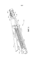
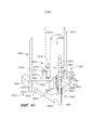
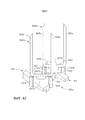
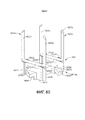
на ФИГ. 1 представлен вид в перспективе варианта осуществления хирургического инструмента и узла удлиненного ствола;in FIG. 1 is a perspective view of an embodiment of a surgical instrument and elongate stem assembly;
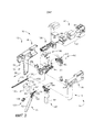
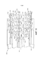
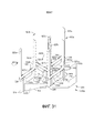
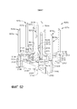
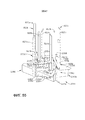
на ФИГ. 2 представлен вид в сборе с пространственным разделением компонентов ручки или участка корпуса хирургического инструмента, показанного на ФИГ. 1;in FIG. 2 is an exploded assembled view of the components of the handle or body portion of the surgical instrument shown in FIG. 1;
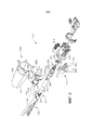
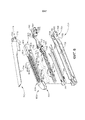
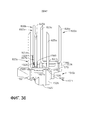
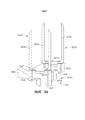
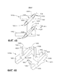
на ФИГ. 3 представлен вид в сборе с пространственным разделением компонентов части узла удлиненного ствола;in FIG. 3 is an exploded view of a portion of the elongate bore assembly;
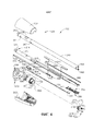
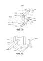
на ФИГ. 4 представлен другой вид в сборе с пространственным разделением компонентов другой части узла удлиненного ствола, показанного на ФИГ. 3;in FIG. 4 is another exploded view of another portion of the elongate barrel assembly shown in FIG. 3;
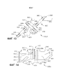
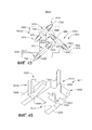
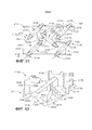
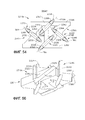
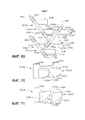
на ФИГ. 5 представлен вид в перспективе части варианта осуществления хирургического концевого эффектора;in FIG. 5 is a perspective view of a portion of an embodiment of a surgical end effector;
на ФИГ. 6 представлен вид в сборе с пространственным разделением компонентов хирургического концевого эффектора, показанного на ФИГ. 5;in FIG. 6 is an exploded view of the components of the surgical end effector shown in FIG. five;
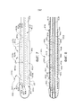
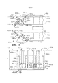
на ФИГ. 7 представлен вид сверху варианта осуществления кассеты с хирургическими скобами;in FIG. 7 is a top view of an embodiment of a surgical staple cartridge;
на ФИГ. 8 представлен вид снизу варианта осуществления кассеты с хирургическими скобами, показанной на ФИГ. 7;in FIG. 8 is a bottom view of an embodiment of the surgical staple cassette shown in FIG. 7;
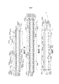
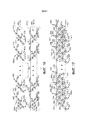
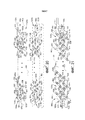
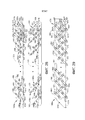
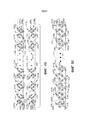
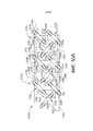
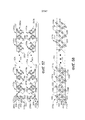
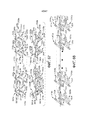
на ФИГ. 9 показан рисунок скоб, размещенных посредством кассеты со скобами, показанной на ФИГ. 7 и 8;in FIG. 9 is a drawing of staples positioned by the staple cassette shown in FIG. 7 and 8;
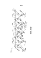
на ФИГ. 10 показан рисунок скоб, показанный на ФИГ. 9, в растянутом состоянии;in FIG. 10 shows the staple pattern shown in FIG. 9, in a stretched state;
на ФИГ. 11 показан предыдущий рисунок скоб, имплантированных в ткань;in FIG. 11 shows a previous drawing of staples implanted in tissue;
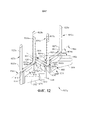
на ФИГ. 12 представлен вид в перспективе варианта осуществления выталкивателя скоб;in FIG. 12 is a perspective view of an embodiment of a staple ejector;
на ФИГ. 13 представлен вид сверху варианта осуществления выталкивателя скоб, показанного на ФИГ. 12;in FIG. 13 is a top view of the embodiment of the staple ejector shown in FIG. 12;
на ФИГ. 14 представлен вид снизу в перспективе выталкивателя скоб, показанного на ФИГ. 12 и 13;in FIG. 14 is a bottom perspective view of the staple ejector shown in FIG. 12 and 13;
на ФИГ. 15 представлен вид снизу в перспективе части варианта осуществления кассеты с хирургическими скобами;in FIG. 15 is a bottom perspective view of a portion of an embodiment of a surgical staple cartridge;
на ФИГ. 16 представлен вид сверху соответствующих матриц выталкивателей, использованных в кассете с хирургическими скобами, показанной на ФИГ. 15;in FIG. 16 is a top plan view of respective ejector arrays used in the surgical staple cassette shown in FIG. 15;
на ФИГ. 17 представлен другой вид сверху одной из матриц выталкивателей, показанных на ФИГ. 16, поддерживаемых в соответствующих участках варианта осуществления кассеты со скобами;in FIG. 17 is another top view of one of the ejector arrays shown in FIG. 16 supported in respective portions of the staple cassette embodiment;
на ФИГ. 18 представлен вид сверху участков матриц выталкивателей, показанных на ФИГ. 16 и 17, в соединении с салазками или кулачковым исполнительным механизмом хирургического инструмента;in FIG. 18 is a top plan view of portions of the ejector arrays shown in FIG. 16 and 17 in conjunction with a slide or cam actuator of a surgical instrument;
на ФИГ. 19 представлен вид спереди в вертикальной проекции матрицы выталкивателей и салазок/кулачкового исполнительного механизма, показанных на ФИГ. 18;in FIG. 19 is a front elevational view of the ejector array and sled / cam actuator shown in FIG. 18;
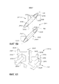
на ФИГ. 20 представлен вид сверху соответствующих участков других вариантов осуществления матриц выталкивателей;in FIG. 20 is a top view of corresponding portions of other embodiments of ejector arrays;
на ФИГ. 21 представлен другой вид сверху одной из матриц выталкивателей, показанных на ФИГ. 20;in FIG. 21 is another top view of one of the ejector arrays shown in FIG. 20;
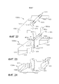
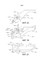
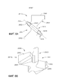
на ФИГ. 22 представлен вид сверху дистального выталкивателя матрицы выталкивателей, показанной на ФИГ. 20;in FIG. 22 is a top view of the distal ejector of the ejector array shown in FIG. 20;
на ФИГ. 23 представлен вид в перспективе дистального выталкивателя, показанного на ФИГ. 22, поддерживающего скобу;in FIG. 23 is a perspective view of the distal ejector shown in FIG. 22 supporting the bracket;
на ФИГ. 24 представлен вид снизу в перспективе дистального выталкивателя, показанного на ФИГ. 22 и 23;in FIG. 24 is a bottom perspective view of the distal ejector shown in FIG. 22 and 23;
на ФИГ. 25 представлен вид сверху проксимального выталкивателя матрицы выталкивателей, показанной на ФИГ. 20;in FIG. 25 is a top view of the proximal ejector of the ejector array shown in FIG. 20;
на ФИГ. 26 представлен вид в перспективе проксимального выталкивателя, показанного на ФИГ. 25, поддерживающего скобу;in FIG. 26 is a perspective view of the proximal ejector shown in FIG. 25 supporting the bracket;
на ФИГ. 27 представлен вид снизу в перспективе проксимального выталкивателя, показанного на ФИГ. 25 и 26; на ФИГ. 28 представлен вид сверху соответствующих участков других вариантов осуществления матриц выталкивателей;in FIG. 27 is a bottom perspective view of the proximal ejector shown in FIG. 25 and 26; in FIG. 28 is a top plan view of corresponding portions of other embodiments of ejector arrays;
на ФИГ. 29 представлен вид сверху одной из матриц выталкивателей, показанных на ФИГ. 28;in FIG. 29 is a top view of one of the ejector arrays shown in FIG. 28;
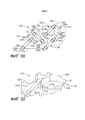
на ФИГ. 30 представлен вид сверху одного из выталкивателей одной из матриц выталкивателей, показанных на ФИГ. 29;in FIG. 30 is a top view of one of the ejectors of one of the ejector arrays shown in FIG. 29;
на ФИГ. 31 показан вид в перспективе выталкивателя, показанного на ФИГ. 30, поддерживающего четыре скобы;in FIG. 31 is a perspective view of the ejector shown in FIG. 30 supporting four braces;
на ФИГ. 32 представлен вид снизу в перспективе выталкивателя, показанного на ФИГ. 30 и 31;in FIG. 32 is a bottom perspective view of the ejector shown in FIG. 30 and 31;
на ФИГ. 33 представлен вид сверху соответствующих участков других вариантов осуществления матриц выталкивателей;in FIG. 33 is a top plan view of corresponding portions of other embodiments of ejector arrays;
на ФИГ. 34 представлен вид сверху одной из матриц выталкивателей, показанных на ФИГ. 33;in FIG. 34 is a top view of one of the ejector arrays shown in FIG. 33;
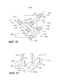
на ФИГ. 35 представлен вид сверху проксимального выталкивателя матрицы выталкивателей, показанной на ФИГ. 34;in FIG. 35 is a top view of the proximal ejector of the ejector array shown in FIG. 34;
на ФИГ. 36 показан вид в перспективе выталкивателя, показанного на ФИГ. 35, поддерживающего три скобы;in FIG. 36 is a perspective view of the ejector shown in FIG. 35 supporting three braces;
на ФИГ. 37 представлен вид снизу в перспективе выталкивателя, показанного на ФИГ. 35 и 36;in FIG. 37 is a bottom perspective view of the ejector shown in FIG. 35 and 36;
на ФИГ. 38 представлен вид сверху дистального выталкивателя матрицы выталкивателей, показанной на ФИГ. 34;in FIG. 38 is a top view of the distal ejector of the ejector array shown in FIG. 34;
на ФИГ. 39 показан вид в перспективе выталкивателя, показанного на ФИГ. 38, поддерживающего две скобы;in FIG. 39 is a perspective view of the ejector shown in FIG. 38 supporting two braces;
на ФИГ. 40 представлен вид снизу в перспективе выталкивателя, показанного на ФИГ. 38 и 39;in FIG. 40 is a bottom perspective view of the ejector shown in FIG. 38 and 39;
на ФИГ. 41 представлен вид сверху соответствующих участков других вариантов осуществления матриц выталкивателей;in FIG. 41 is a top view of corresponding portions of other embodiments of ejector arrays;
на ФИГ. 42 представлен вид сверху одной из матриц выталкивателей, показанных на ФИГ. 41;in FIG. 42 is a top view of one of the ejector arrays shown in FIG. 41;
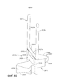
на ФИГ. 43 представлен вид сверху дистального выталкивателя матрицы выталкивателей, показанной на ФИГ. 42;in FIG. 43 is a top view of the distal ejector of the ejector array shown in FIG. 42;
на ФИГ. 44 показан вид в перспективе выталкивателя, показанного на ФИГ. 43, поддерживающего три скобы;in FIG. 44 is a perspective view of the ejector shown in FIG. 43, supporting three braces;
на ФИГ. 45 представлен вид снизу в перспективе выталкивателя, показанного на ФИГ. 43 и 44;in FIG. 45 is a bottom perspective view of the ejector shown in FIG. 43 and 44;
на ФИГ. 46 представлен вид сверху проксимального выталкивателя скоб матрицы выталкивателей, показанной на ФИГ. 42;in FIG. 46 is a top view of a proximal staple ejector of the ejector array shown in FIG. 42;
на ФИГ. 47 показан вид в перспективе выталкивателя, показанного на ФИГ. 46, поддерживающего две скобы;in FIG. 47 is a perspective view of the ejector shown in FIG. 46 supporting two staples;
на ФИГ. 48 представлен вид снизу в перспективе выталкивателя, показанного на ФИГ. 46 и 47;in FIG. 48 is a bottom perspective view of the ejector shown in FIG. 46 and 47;
на ФИГ. 49 представлен вид сверху соответствующих участков других вариантов осуществления матриц выталкивателей;in FIG. 49 is a top plan view of corresponding portions of other embodiments of ejector arrays;
на ФИГ. 50 представлен вид сверху одной из матриц выталкивателей, показанных на ФИГ. 49;in FIG. 50 is a top view of one of the ejector arrays shown in FIG. 49;
на ФИГ. 50A представлен увеличенный вид части матрицы выталкивателей, показанной на ФИГ. 50;in FIG. 50A is an enlarged view of a portion of the ejector array shown in FIG. 50;
на ФИГ. 50B представлен увеличенный вид другой части матрицы выталкивателей, показанной на ФИГ. 50;in FIG. 50B is an enlarged view of another portion of the ejector array shown in FIG. 50;
на ФИГ. 51 представлен вид сверху одного из выталкивателей матрицы выталкивателей, показанной на ФИГ. 50;in FIG. 51 is a top view of one of the ejectors of the ejector array shown in FIG. 50;
на ФИГ. 52 показан вид в перспективе выталкивателя, показанного на ФИГ. 51, поддерживающего всего пять скоб;in FIG. 52 is a perspective view of the ejector shown in FIG. 51 supporting only five staples;
на ФИГ. 53 представлен вид снизу в перспективе выталкивателя, показанного на ФИГ. 51 и 52;in FIG. 53 is a bottom perspective view of the ejector shown in FIG. 51 and 52;
на ФИГ. 54 представлен вид сверху другого выталкивателя матрицы выталкивателей, показанной на ФИГ. 50;in FIG. 54 is a top view of another ejector of the ejector array shown in FIG. 50;
на ФИГ. 55 показан вид в перспективе выталкивателя, показанного на ФИГ. 54, поддерживающего четыре скобы;in FIG. 55 is a perspective view of the ejector shown in FIG. 54 supporting four staples;
на ФИГ. 56 представлен вид снизу в перспективе выталкивателя, показанного на ФИГ. 55;in FIG. 56 is a bottom perspective view of the ejector shown in FIG. 55;
на ФИГ. 57 представлен вид сверху соответствующих участков других вариантов осуществления матриц выталкивателей;in FIG. 57 is a top view of corresponding portions of other embodiments of ejector arrays;
на ФИГ. 58 представлен вид сверху одной из матриц выталкивателей, показанных на ФИГ. 57;in FIG. 58 is a top view of one of the ejector arrays shown in FIG. 57;
на ФИГ. 59 представлен вид сверху дистального выталкивателя матрицы выталкивателей, показанной на ФИГ. 58;in FIG. 59 is a top view of the distal ejector of the ejector array shown in FIG. 58;
на ФИГ. 60 представлен вид в перспективе дистального выталкивателя, показанного на ФИГ. 59, поддерживающего две скобы;in FIG. 60 is a perspective view of the distal ejector shown in FIG. 59 supporting two braces;
на ФИГ. 61 представлен вид снизу в перспективе выталкивателя, показанного на ФИГ. 59 и 60;in FIG. 61 is a bottom perspective view of the ejector shown in FIG. 59 and 60;
на ФИГ. 62 представлен вид сверху соответствующих участков других вариантов осуществления матриц выталкивателей;in FIG. 62 is a top plan view of corresponding portions of other embodiments of ejector arrays;
на ФИГ. 63 представлен вид сверху одной из матриц выталкивателей, показанных на ФИГ. 62, в соединении с частью кассеты с хирургическими скобами;in FIG. 63 is a top view of one of the ejector arrays shown in FIG. 62 in conjunction with a portion of the surgical staple cassette;
на ФИГ. 64 представлен вид сверху одного из выталкивателей матриц выталкивателей, показанных на ФИГ. 62 и 63;in FIG. 64 is a top view of one of the ejector array ejectors shown in FIG. 62 and 63;
на ФИГ. 65 показан вид в перспективе выталкивателя, показанного на ФИГ. 64, поддерживающего одну скобу;in FIG. 65 is a perspective view of the ejector shown in FIG. 64 supporting one bracket;
на ФИГ. 66 представлен вид снизу в перспективе выталкивателя, показанного на ФИГ. 64 и 65;in FIG. 66 is a bottom perspective view of the ejector shown in FIG. 64 and 65;
на ФИГ. 67 представлен вид сверху соответствующих участков других вариантов осуществления матриц выталкивателей;in FIG. 67 is a top plan view of corresponding portions of other embodiments of ejector arrays;
на ФИГ. 68 представлен увеличенный вид сверху одной из матриц выталкивателей, показанных на ФИГ. 67;in FIG. 68 is an enlarged top view of one of the ejector arrays shown in FIG. 67;
на ФИГ. 69 представлен вид сверху первого, второго и третьего вариантов осуществления матриц выталкивателей скоб, показанных на ФИГ. 67 и 68;in FIG. 69 is a top view of the first, second and third embodiments of the staple ejector arrays shown in FIG. 67 and 68;
на ФИГ. 70 представлен вид в перспективе одного из выталкивателей скоб, показанных на ФИГ. 69;in FIG. 70 is a perspective view of one of the staple ejectors shown in FIG. 69;
на ФИГ. 71 представлен вид снизу в перспективе выталкивателя, показанного на ФИГ. 70;in FIG. 71 is a bottom perspective view of the ejector shown in FIG. 70;
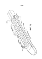
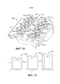
на ФИГ. 72 представлен вид в перспективе кассеты с хирургическими скобами, в которой используются матрицы выталкивателей скоб, показанные на ФИГ. 67 и 68;in FIG. 72 is a perspective view of a surgical staple cartridge using the staple ejector arrays shown in FIG. 67 and 68;
на ФИГ. 73 представлен частичный вид снизу в перспективе кассеты с хирургическими скобами, показанной на ФИГ. 72;in FIG. 73 is a partial bottom perspective view of the surgical staple cartridge shown in FIG. 72;
на ФИГ. 74 представлен вид в перспективе части другого варианта осуществления кассеты с хирургическими скобами; иin FIG. 74 is a perspective view of a portion of another embodiment of a surgical staple cartridge; and
на ФИГ. 75 представлен вид трех сформированных хирургических скоб, которые были сформированы с использованием кассеты с хирургическими скобами, показанной на ФИГ. 74.in FIG. 75 is a view of three formed surgical staples that were formed using the surgical staple cassette shown in FIG. 74.
Соответствующие элементы на разных видах обозначаются соответствующими условными обозначениями. Иллюстративные примеры, представленные в данном документе, демонстрируют различные варианты осуществления изобретения в одной его форме. Эти иллюстративные примеры не следует толковать как ограничивающие объем изобретения каким-либо образом.Corresponding elements in different views are denoted by corresponding symbols. The illustrative examples provided herein demonstrate various embodiments of the invention in one form. These illustrative examples should not be construed as limiting the scope of the invention in any way.
ПОДРОБНОЕ ОПИСАНИЕDETAILED DESCRIPTION
Заявителю настоящей заявки принадлежат представленные ниже заявки на патенты, поданные в тот же день, причем каждая из них полностью включена в настоящий документ путем ссылки:The applicant of this application owns the following patent applications filed on the same day, each of which is incorporated herein by reference in its entirety:
- заявка на патент США № 14/843,196, озаглавленная SURGICAL STAPLE DRIVER ARRAYS, досье патентного поверенного № END7691USNP/150114;- US Patent Application No. 14 / 843,196 entitled SURGICAL STAPLE DRIVER ARRAYS, Patent Attorney File No. END7691USNP / 150114;
- заявка на патент США № 14/843,216, озаглавленная SURGICAL STAPLE CARTRIDGE STAPLE DRIVERS WITH CENTRAL SUPPORT FEATURES, досье патентного поверенного № END7692USNP/150115;- US patent application No. 14 / 843,216 entitled SURGICAL STAPLE CARTRIDGE STAPLE DRIVERS WITH CENTRAL SUPPORT FEATURES, patent attorney dossier No. END7692USNP / 150115;
- заявка на патент США № 14/843,243, озаглавленная SURGICAL STAPLE CONFIGURATIONS WITH CAMMING SURFACES LOCATED BETWEEN PORTIONS SUPPORTING SURGICAL STAPLES, досье патентного поверенного № END7693USNP/150116; и- US patent application No. 14 / 843,243 entitled SURGICAL STAPLE CONFIGURATIONS WITH CAMMING SURFACES LOCATED BETWEEN PORTIONS SUPPORTING SURGICAL STAPLES, patent attorney dossier No. END7693USNP / 150116; and
- заявка на патент США № 14/843,267, озаглавленная SURGICAL STAPLE CARTRIDGES WITH DRIVER ARRANGEMENTS FOR ESTABLISHING HERRINGBONE STAPLE PATTERNS, досье патентного поверенного № END7694USNP/150117.- US patent application No. 14 / 843,267 entitled SURGICAL STAPLE CARTRIDGES WITH DRIVER ARRANGEMENTS FOR ESTABLISHING HERRINGBONE STAPLE PATTERNS, patent attorney dossier No. END7694USNP / 150117.
Заявителю настоящей заявки принадлежат представленные ниже заявки на патенты, поданные 6 марта 2015 г., каждая из которых полностью включена в настоящий документ путем ссылки:The applicant of this application owns the following patent applications filed March 6, 2015, each of which is incorporated herein by reference in its entirety:
- заявка на патент США № 14/640,746, озаглавленная POWERED SURGICAL INSTRUMENT;- US patent application No. 14 / 640,746 entitled POWERED SURGICAL INSTRUMENT;
- заявка на патент США № 14/640,795, озаглавленная MULTIPLE LEVEL THRESHOLDS TO MODIFY OPERATION OF POWERED SURGICAL INSTRUMENTS;- US patent application No. 14 / 640,795 entitled MULTIPLE LEVEL THRESHOLDS TO MODIFY OPERATION OF POWERED SURGICAL INSTRUMENTS;
- заявка на патент США № 14/640,832, озаглавленная ADAPTIVE TISSUE COMPRESSION TECHNIQUES TO ADJUST CLOSURE RATES FOR MULTIPLE TISSUE TYPES; досье патентного поверенного № END7557USNP/140482;- US patent application No. 14 / 640,832 entitled ADAPTIVE TISSUE COMPRESSION TECHNIQUES TO ADJUST CLOSURE RATES FOR MULTIPLE TISSUE TYPES; dossier of patent attorney No. END7557USNP / 140482;
- заявка на патент США № 14/640,935, озаглавленная OVERLAID MULTI SENSOR RADIO FREQUENCY (RF) ELECTRODE SYSTEM TO MEASURE TISSUE COMPRESSION;- US patent application No. 14 / 640,935 entitled OVERLAID MULTI SENSOR RADIO FREQUENCY (RF) ELECTRODE SYSTEM TO MEASURE TISSUE COMPRESSION;
- заявка на патент США № 14/640,831, озаглавленная MONITORING SPEED CONTROL AND PRECISION INCREMENTING OF MOTOR FOR POWERED SURGICAL INSTRUMENTS;- US patent application No. 14 / 640,831 entitled MONITORING SPEED CONTROL AND PRECISION INCREMENTING OF MOTOR FOR POWERED SURGICAL INSTRUMENTS;
- заявка на патент США № 14/640,859, озаглавленная TIME DEPENDENT EVALUATION OF SENSOR DATA TO DETERMINE STABILITY, CREEP, AND VISCOELASTIC ELEMENTS OF MEASURES;- US patent application No. 14 / 640,859 entitled TIME DEPENDENT EVALUATION OF SENSOR DATA TO DETERMINE STABILITY, CREEP, AND VISCOELASTIC ELEMENTS OF MEASURES;
- заявка на патент США № 14/640,817, озаглавленная INTERACTIVE FEEDBACK SYSTEM FOR POWERED SURGICAL INSTRUMENTS;- US patent application No. 14 / 640,817 entitled INTERACTIVE FEEDBACK SYSTEM FOR POWERED SURGICAL INSTRUMENTS;
- заявка на патент США № 14/640,844, озаглавленная CONTROL TECHNIQUES AND SUB-PROCESSOR CONTAINED WITHIN MODULAR SHAFT WITH SELECT CONTROL PROCESSING FROM HANDLE;- US patent application No. 14 / 640,844 entitled CONTROL TECHNIQUES AND SUB-PROCESSOR CONTAINED WITHIN MODULAR SHAFT WITH SELECT CONTROL PROCESSING FROM HANDLE;
- заявка на патент США № 14/640,837, озаглавленная SMART SENSORS WITH LOCAL SIGNAL PROCESSING;- US patent application No. 14 / 640,837 entitled SMART SENSORS WITH LOCAL SIGNAL PROCESSING;
- заявка на патент США № 14/640,765, озаглавленная SYSTEM FOR DETECTING THE MIS-INSERTION OF A STAPLE CARTRIDGE INTO A SURGICAL STAPLER;- US patent application No. 14 / 640,765 entitled SYSTEM FOR DETECTING THE MIS-INSERTION OF A STAPLE CARTRIDGE INTO A SURGICAL STAPLER;
- заявка на патент США № 14/640,799, озаглавленная SIGNAL AND POWER COMMUNICATION SYSTEM POSITIONED ON A ROTATABLE SHAFT; и- US patent application No. 14 / 640,799 entitled SIGNAL AND POWER COMMUNICATION SYSTEM POSITIONED ON A ROTATABLE SHAFT; and
- заявка на патент США № 14/640,780, озаглавленная SURGICAL INSTRUMENT COMPRISING A LOCKABLE BATTERY HOUSING.- US patent application No. 14 / 640,780 entitled SURGICAL INSTRUMENT COMPRISING A LOCKABLE BATTERY HOUSING.
Заявителю настоящей заявки принадлежат представленные ниже заявки на патенты, поданные 27 февраля 2015 г., каждая из которых полностью включена в настоящий документ путем ссылки:The applicant of this application owns the following patent applications filed February 27, 2015, each of which is incorporated herein by reference in its entirety:
- заявка на патент США № 14/633,576, озаглавленная SURGICAL INSTRUMENT SYSTEM COMPRISING AN INSPECTION STATION;- US patent application No. 14 / 633,576 entitled SURGICAL INSTRUMENT SYSTEM COMPRISING AN INSPECTION STATION;
- заявка на патент США № 14/633,546, озаглавленная SURGICAL APPARATUS CONFIGURED TO ASSESS WHETHER A PERFORMANCE PARAMETER OF THE SURGICAL APPARATUS IS WITHIN AN ACCEPTABLE PERFORMANCE BAND;- US patent application No. 14 / 633,546 entitled SURGICAL APPARATUS CONFIGURED TO ASSESS WHETHER A PERFORMANCE PARAMETER OF THE SURGICAL APPARATUS IS WITHIN AN ACCEPTABLE PERFORMANCE BAND;
- заявка на патент США № 14/633,576, озаглавленная SURGICAL CHARGING SYSTEM THAT CHARGES AND/OR CONDITIONS ONE OR MORE BATTERIES;- US patent application No. 14 / 633,576 entitled SURGICAL CHARGING SYSTEM THAT CHARGES AND / OR CONDITIONS ONE OR MORE BATTERIES;
- заявка на патент США № 14/633,566, озаглавленная CHARGING SYSTEM THAT ENABLES EMERGENCY RESOLUTIONS FOR CHARGING A BATTERY;- US patent application No. 14 / 633,566 entitled CHARGING SYSTEM THAT ENABLES EMERGENCY RESOLUTIONS FOR CHARGING A BATTERY;
- заявка на патент США № 14/633,555, озаглавленная SYSTEM FOR MONITORING WHETHER A SURGICAL INSTRUMENT NEEDS TO BE SERVICED;- US patent application No. 14 / 633,555 entitled SYSTEM FOR MONITORING WHETHER A SURGICAL INSTRUMENT NEEDS TO BE SERVICED;
- заявка на патент США № 14/633,542, озаглавленная REINFORCED BATTERY FOR A SURGICAL INSTRUMENT;- US patent application No. 14 / 633,542 entitled REINFORCED BATTERY FOR A SURGICAL INSTRUMENT;
- заявка на патент США № 14/633,548, озаглавленная POWER ADAPTER FOR A SURGICAL INSTRUMENT;- US patent application No. 14 / 633,548 entitled POWER ADAPTER FOR A SURGICAL INSTRUMENT;
- заявка на патент США № 14/633,526, озаглавленная ADAPTABLE SURGICAL INSTRUMENT HANDLE;- US patent application No. 14 / 633,526 entitled ADAPTABLE SURGICAL INSTRUMENT HANDLE;
- заявка на патент США № 14/633,541, озаглавленная MODULAR STAPLING ASSEMBLY; и- US patent application No. 14 / 633,541 entitled MODULAR STAPLING ASSEMBLY; and
- заявка на патент США № 14/633,562, озаглавленная SURGICAL APPARATUS CONFIGURED TO TRACK AN END-OF-LIFE PARAMETER.- US patent application No. 14 / 633,562 entitled SURGICAL APPARATUS CONFIGURED TO TRACK AN END-OF-LIFE PARAMETER.
Заявителю настоящей заявки принадлежат представленные ниже заявки на патенты, поданные 18 декабря 2014 г., каждая из которых полностью включена в настоящий документ путем ссылки:The applicant of this application owns the following patent applications filed December 18, 2014, each of which is incorporated herein by reference in its entirety:
- заявка на патент США № 14/574,478, озаглавленная SURGICAL INSTRUMENT SYSTEMS COMPRISING AN ARTICULATABLE END EFFECTOR AND MEANS FOR ADJUSTING THE FIRING STROKE OF A FIRING;- US patent application No. 14 / 574,478 entitled SURGICAL INSTRUMENT SYSTEMS COMPRISING AN ARTICULATABLE END EFFECTOR AND MEANS FOR ADJUSTING THE FIRING STROKE OF A FIRING;
- заявка на патент США № 14/574,483, озаглавленная SURGICAL INSTRUMENT ASSEMBLY COMPRISING LOCKABLE SYSTEMS;- US patent application No. 14 / 574,483 entitled SURGICAL INSTRUMENT ASSEMBLY COMPRISING LOCKABLE SYSTEMS;
- заявка на патент США № 14/575,139, озаглавленная DRIVE ARRANGEMENTS FOR ARTICULATABLE SURGICAL INSTRUMENTS;- US patent application No. 14 / 575,139 entitled DRIVE ARRANGEMENTS FOR ARTICULATABLE SURGICAL INSTRUMENTS;
- заявка на патент США № 14/575,148, озаглавленная LOCKING ARRANGEMENTS FOR DETACHABLE SHAFT ASSEMBLIES WITH ARTICULATABLE SURGICAL END EFFECTORS;- US patent application No. 14 / 575.148 entitled LOCKING ARRANGEMENTS FOR DETACHABLE SHAFT ASSEMBLIES WITH ARTICULATABLE SURGICAL END EFFECTORS;
- заявка на патент США № 14/575,130, озаглавленная SURGICAL INSTRUMENT WITH AN ANVIL THAT IS SELECTIVELY MOVABLE ABOUT A DISCRETE NON-MOVABLE AXIS RELATIVE TO A STAPLE CARTRIDGE;- US patent application No. 14 / 575,130 entitled SURGICAL INSTRUMENT WITH AN ANVIL THAT IS SELECTIVELY MOVABLE ABOUT A DISCRETE NON-MOVABLE AXIS RELATIVE TO A STAPLE CARTRIDGE;
- заявка на патент США № 14/575,143, озаглавленная SURGICAL INSTRUMENTS WITH IMPROVED CLOSURE ARRANGEMENTS;- US patent application No. 14 / 575,143 entitled SURGICAL INSTRUMENTS WITH IMPROVED CLOSURE ARRANGEMENTS;
- заявка на патент США № 14/575,117, озаглавленная SURGICAL INSTRUMENTS WITH ARTICULATABLE END EFFECTORS AND MOVABLE FIRING BEAM SUPPORT ARRANGEMENTS;- US patent application No. 14 / 575,117 entitled SURGICAL INSTRUMENTS WITH ARTICULATABLE END EFFECTORS AND MOVABLE FIRING BEAM SUPPORT ARRANGEMENTS;
- заявка на патент США № 14/575,154, озаглавленная SURGICAL INSTRUMENTS WITH ARTICULATABLE END EFFECTORS AND IMPROVED FIRING BEAM SUPPORT ARRANGEMENTS;- US patent application No. 14 / 575,154 entitled SURGICAL INSTRUMENTS WITH ARTICULATABLE END EFFECTORS AND IMPROVED FIRING BEAM SUPPORT ARRANGEMENTS;
- заявка на патент США № 14/574,493, озаглавленная SURGICAL INSTRUMENT ASSEMBLY COMPRISING A FLEXIBLE ARTICULATION SYSTEM; и- US patent application No. 14 / 574,493 entitled SURGICAL INSTRUMENT ASSEMBLY COMPRISING A FLEXIBLE ARTICULATION SYSTEM; and
- заявка на патент США № 14/574,500, озаглавленная SURGICAL INSTRUMENT ASSEMBLY COMPRISING A LOCKABLE ARTICULATION SYSTEM.- US patent application No. 14 / 574,500 entitled SURGICAL INSTRUMENT ASSEMBLY COMPRISING A LOCKABLE ARTICULATION SYSTEM.
Заявителю настоящей заявки принадлежат представленные ниже заявки на патенты, поданные 1 марта 2013 г., каждая из которых полностью включена в настоящий документ путем ссылки:The applicant of this application owns the following patent applications filed on March 1, 2013, each of which is incorporated herein by reference in its entirety:
- заявка на патент США № 13/782,295, озаглавленная Articulatable Surgical Instruments With Conductive Pathways For Signal Communication, в настоящее время публикация заявки на патент США № 2014/0246471;- US Patent Application No. 13 / 782,295 entitled Articulatable Surgical Instruments With Conductive Pathways For Signal Communication, now US Patent Application Publication No. 2014/0246471;
- заявка на патент США № 13/782,323, озаглавленная Rotary Powered Articulation Joints For Surgical Instruments, в настоящее время публикация заявки на патент США № 2014/0246472;- US patent application No. 13 / 782,323 entitled Rotary Powered Articulation Joints For Surgical Instruments, now US patent application publication No. 2014/0246472;
- заявка на патент США № 13/782,338, озаглавленная Thumbwheel Switch Arrangements For Surgical Instruments, в настоящее время публикация заявки на патент США № 2014/0249557;- US patent application No. 13 / 782,338 entitled Thumbwheel Switch Arrangements For Surgical Instruments, now US patent application publication No. 2014/0249557;
- заявка на патент США № 13/782,499, озаглавленная Electromechanical Surgical Device with Signal Relay Arrangement, в настоящее время публикация заявки на патент США № 2014/0246474;- US patent application No. 13 / 782,499 entitled Electromechanical Surgical Device with Signal Relay Arrangement, currently US patent application publication No. 2014/0246474;
- заявка на патент США № 13/782,460, озаглавленная Multiple Processor Motor Control for Modular Surgical Instruments, в настоящее время публикация заявки на патент США № 2014/0246478;- US Patent Application No. 13 / 782,460 entitled Multiple Processor Motor Control for Modular Surgical Instruments, currently US Patent Application Publication No. 2014/0246478;
- заявка на патент США № 13/782,358, озаглавленная Joystick Switch Assemblies For Surgical Instruments, в настоящее время патентная публикация США № 2014/0246477;- US patent application No. 13 / 782,358 entitled Joystick Switch Assemblies For Surgical Instruments, now US Patent Publication No. 2014/0246477;
- заявка на патент США № 13/782,481, озаглавленная Sensor Straightened End Effector During Removal Through Trocar, в настоящее время публикация заявки на патент США № 2014/0246479;- US Patent Application No. 13 / 782,481 entitled Sensor Straightened End Effector During Removal Through Trocar, now US Patent Application Publication No. 2014/0246479;
- заявка на патент США № 13/782,518, озаглавленная Control Methods for Surgical Instruments with Removable Implement Portions, в настоящее время публикация заявки на патент США № 2014/0246475;- U.S. Patent Application No. 13 / 782,518 entitled Control Methods for Surgical Instruments with Removable Implement Portions, currently U.S. Patent Application Publication No. 2014/0246475;
- заявка на патент США № 13/782,375, озаглавленная Rotary Powered Surgical Instruments With Multiple Degrees of Freedom, в настоящее время публикация заявки на патент США № 2014/0246473; и- US patent application No. 13 / 782,375 entitled Rotary Powered Surgical Instruments With Multiple Degrees of Freedom, currently US patent application publication No. 2014/0246473; and
- заявка на патент США № 13/782,536, озаглавленная Surgical Instrument Soft Stop, в настоящее время публикация заявки на патент США № 2014/0246476.- US Patent Application No. 13 / 782,536 entitled Surgical Instrument Soft Stop, currently US Patent Application Publication No. 2014/0246476.
Заявителю настоящей заявки также принадлежат представленные ниже заявки на патенты, поданные 14 марта 2013 г., каждая из которых полностью включена в настоящий документ путем ссылки:The applicant of this application also owns the following patent applications filed March 14, 2013, each of which is incorporated herein by reference in its entirety:
- заявка на патент США № 13/803,097, озаглавленная ARTICULATABLE SURGICAL INSTRUMENT COMPRISING A FIRING DRIVE, в настоящее время публикация заявки на патент США № 2014/0263542;- US Patent Application No. 13 / 803,097 entitled ARTICULATABLE SURGICAL INSTRUMENT COMPRISING A FIRING DRIVE, currently US Patent Application Publication No. 2014/0263542;
- заявка на патент США № 13/803,193, озаглавленная CONTROL ARRANGEMENTS FOR A DRIVE MEMBER OF A SURGICAL INSTRUMENT, в настоящее время публикация заявки на патент США № 2014/0263537;- US Patent Application No. 13 / 803,193 entitled CONTROL ARRANGEMENTS FOR A DRIVE MEMBER OF A SURGICAL INSTRUMENT, currently US Patent Application Publication No. 2014/0263537;
- заявка на патент США № 13/803,053, озаглавленная INTERCHANGEABLE SHAFT ASSEMBLIES FOR USE WITH A SURGICAL INSTRUMENT, в настоящее время публикация заявки на патент США № 2014/0263564;- US Patent Application No. 13 / 803,053 entitled INTERCHANGEABLE SHAFT ASSEMBLIES FOR USE WITH A SURGICAL INSTRUMENT, currently US Patent Application Publication No. 2014/0263564;
- заявка на патент США № 13/803,086, озаглавленная ARTICULATABLE SURGICAL INSTRUMENT COMPRISING AN ARTICULATION LOCK, в настоящее время публикация заявки на патент США № 2014/0263541;- US Patent Application No. 13 / 803,086 entitled ARTICULATABLE SURGICAL INSTRUMENT COMPRISING AN ARTICULATION LOCK, currently US Patent Application Publication No. 2014/0263541;
- заявка на патент США № 13/803,210, озаглавленная SENSOR ARRANGEMENTS FOR ABSOLUTE POSITIONING SYSTEM FOR SURGICAL INSTRUMENTS, в настоящее время публикация заявки на патент США № 2014/0263538;US Patent Application No. 13 / 803,210 entitled SENSOR ARRANGEMENTS FOR ABSOLUTE POSITIONING SYSTEM FOR SURGICAL INSTRUMENTS, currently US Patent Application Publication No. 2014/0263538;
- заявка на патент США № 13/803,148, озаглавленная MULTI-FUNCTION MOTOR FOR A SURGICAL INSTRUMENT, в настоящее время публикация заявки на патент США № 2014/0263554;US Patent Application No. 13 / 803,148 entitled MULTI-FUNCTION MOTOR FOR A SURGICAL INSTRUMENT, currently US Patent Application Publication No. 2014/0263554;
- заявка на патент США № 13/803,066, озаглавленная DRIVE SYSTEM LOCKOUT ARRANGEMENTS FOR MODULAR SURGICAL INSTRUMENTS, в настоящее время публикация заявки на патент США № 2014/0263565;- US Patent Application No. 13 / 803,066 entitled DRIVE SYSTEM LOCKOUT ARRANGEMENTS FOR MODULAR SURGICAL INSTRUMENTS, currently US Patent Application Publication No. 2014/0263565;
- заявка на патент США № 13/803,117, озаглавленная ARTICULATION CONTROL SYSTEM FOR ARTICULATABLE SURGICAL INSTRUMENTS, в настоящее время публикация заявки на патент США № 2014/0263553;- US patent application No. 13 / 803,117, entitled ARTICULATION CONTROL SYSTEM FOR ARTICULATABLE SURGICAL INSTRUMENTS, currently US patent application publication No. 2014/0263553;
- заявка на патент США № 13/803,130, озаглавленная DRIVE TRAIN CONTROL ARRANGEMENTS FOR MODULAR SURGICAL INSTRUMENTS, в настоящее время публикация заявки на патент США № 2014/0263543; и- US Patent Application No. 13 / 803,130 entitled DRIVE TRAIN CONTROL ARRANGEMENTS FOR MODULAR SURGICAL INSTRUMENTS, currently US Patent Application Publication No. 2014/0263543; and
- заявка на патент США № 13/803,159, озаглавленная METHOD AND SYSTEM FOR OPERATING A SURGICAL INSTRUMENT, в настоящее время публикация заявки на патент США № 2014/0277017.- US Patent Application No. 13 / 803,159 entitled METHOD AND SYSTEM FOR OPERATING A SURGICAL INSTRUMENT, currently US Patent Application Publication No. 2014/0277017.
Заявителю настоящей заявки принадлежит представленная ниже заявка на патент, поданная 7 марта 2014 г., которая полностью включена в настоящий документ путем ссылки:The applicant of this application belongs to the following patent application filed on March 7, 2014, which is fully incorporated into this document by reference:
- заявка на патент США № 14/200,111, озаглавленная CONTROL SYSTEMS FOR SURGICAL INSTRUMENTS, в настоящее время публикация заявки на патент США № 2014/0263539.- US Patent Application No. 14 / 200,111 entitled CONTROL SYSTEMS FOR SURGICAL INSTRUMENTS, currently US Patent Application Publication No. 2014/0263539.
Заявителю настоящей заявки также принадлежат представленные ниже заявки на патенты, поданные 26 марта 2014 г., каждая из которых полностью включена в настоящий документ путем ссылки:The applicant of this application also owns the following patent applications filed on March 26, 2014, each of which is incorporated herein by reference in its entirety:
- заявка на патент США № 14/226,106, озаглавленная POWER MANAGEMENT CONTROL SYSTEMS FOR SURGICAL INSTRUMENTS;- US patent application No. 14 / 226,106 entitled POWER MANAGEMENT CONTROL SYSTEMS FOR SURGICAL INSTRUMENTS;
- заявка на патент США № 14/226,099, озаглавленная STERILIZATION VERIFICATION CIRCUIT;- US patent application No. 14 / 226,099 entitled STERILIZATION VERIFICATION CIRCUIT;
- заявка на патент США № 14/226,094, озаглавленная VERIFICATION OF NUMBER OF BATTERY EXCHANGES/PROCEDURE COUNT;- US patent application No. 14 / 226,094 entitled VERIFICATION OF NUMBER OF BATTERY EXCHANGES / PROCEDURE COUNT;
- заявка на патент США № 14/226,117, озаглавленная POWER MANAGEMENT THROUGH SLEEP OPTIONS OF SEGMENTED CIRCUIT AND WAKE UP CONTROL;- US patent application No. 14 / 226,117 entitled POWER MANAGEMENT THROUGH SLEEP OPTIONS OF SEGMENTED CIRCUIT AND WAKE UP CONTROL;
- заявка на патент США № 14/226,075, озаглавленная MODULAR POWERED SURGICAL INSTRUMENT WITH DETACHABLE SHAFT ASSEMBLIES;- US patent application No. 14 / 226,075 entitled MODULAR POWERED SURGICAL INSTRUMENT WITH DETACHABLE SHAFT ASSEMBLIES;
- заявка на патент США № 14/226,093, озаглавленная FEEDBACK ALGORITHMS FOR MANUAL BAILOUT SYSTEMS FOR SURGICAL INSTRUMENTS;- US patent application No. 14 / 226,093 entitled FEEDBACK ALGORITHMS FOR MANUAL BAILOUT SYSTEMS FOR SURGICAL INSTRUMENTS;
- заявка на патент США № 14/226,116, озаглавленная SURGICAL INSTRUMENT UTILIZING SENSOR ADAPTATION;- US patent application No. 14 / 226,116 entitled SURGICAL INSTRUMENT UTILIZING SENSOR ADAPTATION;
- заявка на патент США № 14/226,071, озаглавленная SURGICAL INSTRUMENT CONTROL CIRCUIT HAVING A SAFETY PROCESSOR;- US patent application No. 14 / 226,071 entitled SURGICAL INSTRUMENT CONTROL CIRCUIT HAVING A SAFETY PROCESSOR;
- заявка на патент США № 14/226,097, озаглавленная SURGICAL INSTRUMENT COMPRISING INTERACTIVE SYSTEMS;- US patent application No. 14 / 226,097 entitled SURGICAL INSTRUMENT COMPRISING INTERACTIVE SYSTEMS;
- заявка на патент США № 14/226,126, озаглавленная INTERFACE SYSTEMS FOR USE WITH SURGICAL INSTRUMENTS;- US patent application No. 14 / 226,126 entitled INTERFACE SYSTEMS FOR USE WITH SURGICAL INSTRUMENTS;
- заявка на патент США № 14/226,133, озаглавленная MODULAR SURGICAL INSTRUMENT SYSTEM;- US patent application No. 14 / 226,133 entitled MODULAR SURGICAL INSTRUMENT SYSTEM;
- заявка на патент США № 14/226,081, озаглавленная SYSTEMS AND METHODS FOR CONTROLLING A SEGMENTED CIRCUIT;- US patent application No. 14 / 226,081 entitled SYSTEMS AND METHODS FOR CONTROLLING A SEGMENTED CIRCUIT;
- заявка на патент США № 14/226,076, озаглавленная POWER MANAGEMENT THROUGH SEGMENTED CIRCUIT AND VARIABLE VOLTAGE PROTECTION;- US patent application No. 14 / 226,076 entitled POWER MANAGEMENT THROUGH SEGMENTED CIRCUIT AND VARIABLE VOLTAGE PROTECTION;
- заявка на патент США № 14/226,111, озаглавленная SURGICAL STAPLING INSTRUMENT SYSTEM; и- US patent application No. 14 / 226,111 entitled SURGICAL STAPLING INSTRUMENT SYSTEM; and
- заявка на патент США № 14/226,125, озаглавленная SURGICAL INSTRUMENT COMPRISING A ROTATABLE SHAFT.- US patent application No. 14 / 226,125 entitled SURGICAL INSTRUMENT COMPRISING A ROTATABLE SHAFT.
Заявителю настоящей заявки также принадлежат представленные ниже заявки на патенты, поданные 5 сентября 2014 г., каждая из которых полностью включена в настоящий документ путем ссылки:The applicant of this application also owns the following patent applications filed September 5, 2014, each of which is incorporated herein by reference in its entirety:
- заявка на патент США № 14/479,103, озаглавленная CIRCUITRY AND SENSORS FOR POWERED MEDICAL DEVICE;- US patent application No. 14 / 479,103 entitled CIRCUITRY AND SENSORS FOR POWERED MEDICAL DEVICE;
- заявка на патент США № 14/479,119, озаглавленная ADJUNCT WITH INTEGRATED SENSORS TO QUANTIFY TISSUE COMPRESSION;- US patent application No. 14 / 479,119 entitled ADJUNCT WITH INTEGRATED SENSORS TO QUANTIFY TISSUE COMPRESSION;
- заявка на патент США № 14/478,908, озаглавленная MONITORING DEVICE DEGRADATION BASED ON COMPONENT EVALUATION;- US patent application No. 14 / 478,908 entitled MONITORING DEVICE DEGRADATION BASED ON COMPONENT EVALUATION;
- заявка на патент США № 14/478,895, озаглавленная MULTIPLE SENSORS WITH ONE SENSOR AFFECTING A SECOND SENSOR'S OUTPUT OR INTERPRETATION;- US patent application No. 14 / 478,895 entitled MULTIPLE SENSORS WITH ONE SENSOR AFFECTING A SECOND SENSOR'S OUTPUT OR INTERPRETATION;
- заявка на патент США № 14/479,110, озаглавленная USE OF POLARITY OF HALL MAGNET DETECTION TO DETECT MISLOADED CARTRIDGE;- US patent application No. 14 / 479,110 entitled USE OF POLARITY OF HALL MAGNET DETECTION TO DETECT MISLOADED CARTRIDGE;
- заявка на патент США № 14/479,098, озаглавленная SMART CARTRIDGE WAKE UP OPERATION AND DATA RETENTION;- US patent application No. 14 / 479,098 entitled SMART CARTRIDGE WAKE UP OPERATION AND DATA RETENTION;
- заявка на патент США № 14/479,115, озаглавленная MULTIPLE MOTOR CONTROL FOR POWERED MEDICAL DEVICE; и- US patent application No. 14 / 479,115 entitled MULTIPLE MOTOR CONTROL FOR POWERED MEDICAL DEVICE; and
- заявка на патент США № 14/479,108, озаглавленная LOCAL DISPLAY OF TISSUE PARAMETER STABILIZATION.- US patent application No. 14 / 479,108 entitled LOCAL DISPLAY OF TISSUE PARAMETER STABILIZATION.
Заявителю настоящей заявки также принадлежат представленные ниже заявки на патенты, поданные 9 апреля 2014 г., каждая из которых полностью включена в настоящий документ путем ссылки:The applicant of this application also owns the following patent applications filed on April 9, 2014, each of which is incorporated herein by reference in its entirety:
- заявка на патент США № 14/248,590, озаглавленная MOTOR DRIVEN SURGICAL INSTRUMENTS WITH LOCKABLE DUAL DRIVE SHAFTS, в настоящее время публикация заявки на патент США № 2014/0305987;US Patent Application No. 14 / 248,590 entitled MOTOR DRIVEN SURGICAL INSTRUMENTS WITH LOCKABLE DUAL DRIVE SHAFTS, currently US Patent Application Publication No. 2014/0305987;
- заявка на патент США № 14/248,581, озаглавленная SURGICAL INSTRUMENT COMPRISING A CLOSING DRIVE AND A FIRING DRIVE OPERATED FROM THE SAME ROTATABLE OUTPUT, в настоящее время публикация заявки на патент США № 2014/0305989;US Patent Application No. 14 / 248,581 entitled SURGICAL INSTRUMENT COMPRISING A CLOSING DRIVE AND A FIRING DRIVE OPERATED FROM THE SAME ROTATABLE OUTPUT, currently US Patent Application Publication No. 2014/0305989;
- заявка на патент США № 14/248,595, озаглавленная SURGICAL INSTRUMENT SHAFT INCLUDING SWITCHES FOR CONTROLLING THE OPERATION OF THE SURGICAL INSTRUMENT, в настоящее время публикация заявки на патент США № 2014/0305988;- US Patent Application No. 14 / 248,595 entitled SURGICAL INSTRUMENT SHAFT INCLUDING SWITCHES FOR CONTROLLING THE OPERATION OF THE SURGICAL INSTRUMENT, currently US Patent Application Publication No. 2014/0305988;
- заявка на патент США № 14/248,588, озаглавленная POWERED LINEAR SURGICAL STAPLER, в настоящее время публикация заявки на патент США № 2014/0309666;US Patent Application No. 14 / 248,588 entitled POWERED LINEAR SURGICAL STAPLER, currently US Patent Application Publication No. 2014/0309666;
- заявка на патент США № 14/248,591, озаглавленная TRANSMISSION ARRANGEMENT FOR A SURGICAL INSTRUMENT, в настоящее время публикация заявки на патент США № 2014/0305991;- US patent application No. 14 / 248,591, entitled TRANSMISSION ARRANGEMENT FOR A SURGICAL INSTRUMENT, currently US patent application publication No. 2014/0305991;
- заявка на патент США 14/248,584, озаглавленная MODULAR MOTOR DRIVEN SURGICAL INSTRUMENTS WITH ALIGNMENT FEATURES FOR ALIGNING ROTARY DRIVE SHAFTS WITH SURGICAL END EFFECTOR SHAFTS, в настоящее время публикация заявки на патент США № 2014/0305994;-
- заявка на патент США № 14/248,587, озаглавленная POWERED SURGICAL STAPLER, в настоящее время публикация заявки на патент США № 2014/0309665;- US patent application No. 14 / 248,587, entitled POWERED SURGICAL STAPLER, currently US patent application publication No. 2014/0309665;
- заявка на патент США № 14/248,586, озаглавленная DRIVE SYSTEM DECOUPLING ARRANGEMENT FOR A SURGICAL INSTRUMENT, в настоящее время публикация заявки на патент США № 2014/0305990; и- US Patent Application No. 14 / 248,586 entitled DRIVE SYSTEM DECOUPLING ARRANGEMENT FOR A SURGICAL INSTRUMENT, currently US Patent Application Publication No. 2014/0305990; and
- заявка на патент США № 14/248,607, озаглавленная MODULAR MOTOR DRIVEN SURGICAL INSTRUMENTS WITH STATUS INDICATION ARRANGEMENTS, в настоящее время публикация заявки на патент США № 2014/0305992.US Patent Application No. 14 / 248,607 entitled MODULAR MOTOR DRIVEN SURGICAL INSTRUMENTS WITH STATUS INDICATION ARRANGEMENTS, currently US Patent Application Publication No. 2014/0305992.
Заявителю настоящей заявки также принадлежат представленные ниже заявки на патенты, поданные 16 апреля 2013 г., каждая из которых полностью включена в настоящий документ путем ссылки:The applicant of this application also owns the following patent applications filed April 16, 2013, each of which is incorporated herein by reference in its entirety:
- предварительная заявка на патент США № 61/812,365, озаглавленная SURGICAL INSTRUMENT WITH MULTIPLE FUNCTIONS PERFORMED BY A SINGLE MOTOR;- US Provisional Patent Application No. 61 / 812,365 entitled SURGICAL INSTRUMENT WITH MULTIPLE FUNCTIONS PERFORMED BY A SINGLE MOTOR;
- предварительная заявка на патент США № 61/812,376, озаглавленная LINEAR CUTTER WITH POWER;- US Provisional Patent Application No. 61 / 812,376 entitled LINEAR CUTTER WITH POWER;
- предварительная заявка на патент США № 61/812,382, озаглавленная LINEAR CUTTER WITH MOTOR AND PISTOL GRIP;- US Provisional Patent Application No. 61 / 812,382 entitled LINEAR CUTTER WITH MOTOR AND PISTOL GRIP;
- предварительная заявка на патент США № 61/812,385, озаглавленная SURGICAL INSTRUMENT HANDLE WITH MULTIPLE ACTUATION MOTORS AND MOTOR CONTROL; и- US Provisional Patent Application No. 61 / 812,385 entitled SURGICAL INSTRUMENT HANDLE WITH MULTIPLE ACTUATION MOTORS AND MOTOR CONTROL; and
- предварительная заявка на патент США № 61/812,372, озаглавленная SURGICAL INSTRUMENT WITH MULTIPLE FUNCTIONS PERFORMED BY A SINGLE MOTOR.- US Provisional Patent Application No. 61 / 812,372 entitled SURGICAL INSTRUMENT WITH MULTIPLE FUNCTIONS PERFORMED BY A SINGLE MOTOR.
В настоящем документе приведена различная подробная информация, необходимая для понимания общей конструкции, функциональности, особенностей изготовления и применения вариантов осуществления, описание которых представлено в настоящем документе и проиллюстрировано сопроводительными рисунками. Хорошо известные принципы работы, компоненты и элементы не получили в настоящем документе подробного описания, чтобы не затруднять понимание вариантов осуществления, описанных в настоящем документе. Читатель должен понимать, что варианты осуществления, описанные и проиллюстрированные в настоящем документе, являются не имеющими ограничительного характера примерами. Таким образом, следует понимать, что определенные конструктивные и функциональные особенности, описанные в данном документе, могут иметь показательный или пояснительный характер. Изменения и модификации вариантов осуществления, описанных и проиллюстрированных в данном документе, могут выполняться в пределах объема формулы изобретения.This document provides various detailed information required to understand the general design, functionality, manufacturing and application of the embodiments described herein and illustrated in the accompanying drawings. Well-known operating principles, components, and elements have not been described in detail herein, so as not to obscure the understanding of the embodiments described herein. The reader should understand that the embodiments described and illustrated herein are non-limiting examples. Thus, it should be understood that certain design and functional features described in this document may be indicative or explanatory. Variations and modifications to the embodiments described and illustrated herein may be made within the scope of the claims.
Термины «содержать» (и любые его формы, такие как «содержит» и «содержащий»), «иметь» (и любые его формы, такие как «имеет» и «имеющий»), «включать в себя» (и любые его формы, такие как «включает в себя» и «включающий в себя») и «вмещать» (и любые его формы, такие как «вмещает» и «вмещающий») представляют собой неограниченные связующие глаголы. Таким образом, хирургическая система или устройство, которые «содержат», «имеют», «включают в себя» или «вмещают» один или более элементов, обладают этим одним или более элементами, но обладание не ограничивается только этим одним или более элементами. Аналогично элемент системы или устройства, которые «содержат», «имеют», «включают в себя» или «вмещают» один или более элементов, обладают этим одним или более элементами, но обладание не ограничивается только этим одним или более элементами.The terms “comprise” (and any of its forms such as “contains” and “containing”), “have” (and any of its forms such as “has” and “having”), “include” (and any forms such as "includes" and "includes") and "contain" (and any of its forms such as "contains" and "containing") are unrestricted linking verbs. Thus, a surgical system or device that “contains,” “has,” “includes,” or “contains” one or more features, has one or more features, but is not limited to only that one or more features. Likewise, a system element or devices that “contain,” “have,” “include,” or “contain” one or more elements, possess that one or more elements, but are not limited to only that one or more elements.
Термины «проксимальный» и «дистальный» в настоящем документе определяются относительно врача, управляющего ручкой хирургического инструмента. Термин «проксимальный» относится к участку, расположенному ближе всего к врачу, а термин «дистальный» относится к участку, удаленному от врача. Кроме того, для удобства и ясности применительно к рисункам в настоящем документе предлагается использовать такие пространственные термины, как «вертикальный», «горизонтальный», «вверх» и «вниз». Однако, поскольку применение хирургических инструментов предполагает множество ориентаций и положений, эти термины не следует толковать как ограничивающие и/или абсолютные.The terms "proximal" and "distal" are defined herein with respect to the physician operating the handle of the surgical instrument. The term "proximal" refers to the site closest to the physician, and the term "distal" refers to the site farthest from the physician. In addition, for convenience and clarity, the use of spatial terms such as "vertical", "horizontal", "up" and "down" in relation to figures in this document. However, since the use of surgical instruments involves many orientations and positions, these terms should not be construed as limiting and / or absolute.
Для выполнения лапароскопических и минимально инвазивных хирургических вмешательств предложены различные примеры устройств и способов. Однако читателю сразу станет понятно, что различные способы и устройства, описанные в настоящем документе, можно применять в множестве хирургических вмешательств и сфер применения, включая, например, те, что связаны с открытыми хирургическими вмешательствами. По ходу данного подробного описания читатель сможет дополнительно оценить, что разнообразные инструменты, описанные в данном документе, можно вводить в тело любым способом - как через естественные отверстия, так и через разрез или пункционное отверстие, выполненное в тканях, и т. п. Рабочие части или части концевых эффекторов таких инструментов можно вводить непосредственно в тело пациента или через устройство доступа, которое имеет рабочий канал, через который можно проводить концевой эффектор и удлиненный ствол хирургического инструмента.Various examples of devices and methods have been proposed for performing laparoscopic and minimally invasive surgical procedures. However, the reader will immediately recognize that the various methods and devices described herein can be used in a variety of surgical procedures and applications, including, for example, those associated with open surgery. In the course of this detailed description, the reader will be able to further appreciate that the various instruments described in this document can be inserted into the body in any way - either through natural openings or through an incision or puncture hole made in tissues, etc. Working parts or portions of the end effectors of such instruments can be inserted directly into the patient's body or through an access device that has a working channel through which the end effector and an elongated stem of the surgical instrument can be passed.
Хирургическая сшивающая система может содержать ствол и проходящий от ствола концевой эффектор. Концевой эффектор может содержать первую браншу и вторую браншу. Первая бранша содержит кассету со скобами. Кассета со скобами выполнена с возможностью вставки в первую браншу и удаления из нее; однако предусмотрены другие варианты осуществления, в которых кассета со скобами выполнена без возможности извлечения из первой бранши или по меньшей мере выполнена с возможностью быстрой замены из первой бранши. Вторая бранша содержит упор, выполненный с возможностью деформации скоб, выталкиваемых из кассеты со скобами. Вторая бранша выполнена с возможностью поворота относительно первой бранши вокруг оси закрытия; однако предусмотрены другие варианты осуществления, в которых первая бранша выполнена с возможностью поворота относительно второй бранши. Хирургическая сшивающая система дополнительно содержит шарнирное сочленение, выполненное с возможностью обеспечения вращения или шарнирного поворота концевого эффектора относительно ствола. Концевой эффектор выполнен с возможностью вращения вокруг оси шарнирного поворота, проходящей через шарнирное сочленение. Предусмотрены другие варианты осуществления, которые не включают в себя шарнирного сочленения.The surgical stapling system may comprise a stem and an end effector extending from the stem. The end effector may comprise a first jaw and a second jaw. The first branch contains a staple cassette. The cassette with staples is designed to be inserted into and removed from the first branch; however, other embodiments are contemplated in which the staple cartridge is non-removable from the first jaw, or at least is quick-replaceable from the first jaw. The second branch contains a stop made with the possibility of deformation of the staples ejected from the cassette with staples. The second jaw is made with the possibility of rotation relative to the first jaw about the closing axis; however, other embodiments are contemplated in which the first jaw is rotatable relative to the second jaw. The surgical stapling system further comprises a pivot joint configured to rotate or pivot the end effector relative to the shaft. The end effector is rotatable about a pivot pivot axis passing through the pivot joint. Other embodiments are contemplated that do not include an articulated joint.
Кассета со скобами содержит корпус кассеты. Корпус кассеты включает в себя проксимальный конец, дистальный конец и платформу, проходящую между проксимальным концом и дистальным концом. В процессе применения кассета со скобами расположена на первой стороне ткани, подлежащей сшиванию, а упор расположен на второй стороне ткани. Упор перемещается к кассете со скобами для сжатия и прижимания ткани к платформе. После этого скобы, хранящиеся в корпусе кассеты с возможностью извлечения, можно размещать в ткани. Корпус кассеты включает в себя сформированные в нем полости для скоб, при этом скобы хранятся в полостях для скоб с возможностью извлечения. Полости для скоб расположены в шесть продольных рядов. Три ряда полостей для скоб расположены на первой стороне продольного паза, и три ряда полостей для скоб расположены на второй стороне продольного паза. Возможны другие конструкции скоб и полостей для скоб.The staple cassette contains the cassette body. The cassette body includes a proximal end, a distal end, and a platform extending between the proximal end and the distal end. In use, the staple cassette is positioned on the first side of the fabric to be stitched and the abutment is positioned on the second side of the fabric. The stop moves to the cassette with staples to compress and press the fabric against the platform. Thereafter, the staples stored in the removable cassette body can be placed in the tissue. The cassette body includes staple cavities formed therein, and the staples are removably stored in the staple cavities. The staple cavities are arranged in six longitudinal rows. Three rows of staple cavities are located on the first side of the longitudinal groove and three rows of staple cavities are located on the second side of the longitudinal groove. Other designs of staples and staple cavities are possible.
Скобы поддерживаются в корпусе кассеты с помощью выталкивателей скоб. Выталкиватели выполнены с возможностью перемещения между первым, или неактивированным, положением и вторым, или активированным, положением для выталкивания скоб из полостей для скоб. Выталкиватели поддерживаются в корпусе кассеты с помощью фиксатора, который проходит вокруг нижней части корпуса кассеты и включает в себя упругие элементы, выполненные с возможностью захвата корпуса кассеты и фиксации фиксатора относительно корпуса кассеты. Выталкиватели выполнены с возможностью перемещения между их неактивированными положениями и их активированными положениями с помощью салазок. Салазки выполнены с возможностью перемещения между проксимальным положением, смежным с проксимальным концом, и дистальным положением, смежным с дистальным концом. Салазки содержат множество наклонных поверхностей, выполненных с возможностью скольжения под выталкивателями и подъема выталкивателей и поддерживаемых на них скоб к упору.The staples are supported in the cassette body using staple ejectors. The ejectors are movable between a first, or non-activated, position and a second, or activated, position for pushing the staples out of the staple cavities. The ejectors are supported in the cassette body by a retainer that extends around the bottom of the cassette body and includes resilient members configured to grip the cassette body and fix the retainer relative to the cassette body. The ejectors are made with the possibility of moving between their non-activated positions and their activated positions using a slide. The slide is movable between a proximal position adjacent to the proximal end and a distal position adjacent to the distal end. The slide contains a plurality of inclined surfaces made with the possibility of sliding under the ejectors and lifting the ejectors and the brackets supported on them against the stop.
В дополнение к указанному выше, салазки перемещаются дистально с помощью пускового элемента. Пусковой элемент выполнен с возможностью контакта с салазками и проталкивания салазок к дистальному концу. Продольный паз, сформированный в корпусе кассеты, выполнен с возможностью размещения пускового элемента. Упор также включает в себя паз, выполненный с возможностью размещения пускового элемента. Пусковой элемент дополнительно содержит первый кулачок, который взаимодействует с первой браншей, и второй кулачок, который взаимодействует со второй браншей. При дистальном выдвижении пускового элемента первый кулачок и второй кулачок позволяют контролировать расстояние, или тканевый зазор, между платформой кассеты со скобами и упором. Пусковой элемент также содержит скальпель, выполненный с возможностью рассечения ткани, захваченной между кассетой со скобами и упором. Желательно по меньшей мере частично располагать скальпель проксимально по отношению к наклонным поверхностям таким образом, чтобы скобы выталкивались раньше скальпеля.In addition to the above, the slide is moved distally by the trigger. The trigger element is adapted to contact with the slide and push the slide towards the distal end. The longitudinal groove formed in the cassette body is configured to accommodate the trigger. The stop also includes a groove configured to receive the trigger. The trigger further comprises a first cam that interacts with the first jaws and a second cam that interacts with the second jaws. When the trigger is distally extended, the first cam and the second cam allow control of the distance, or tissue gap, between the platform of the staple cassette and the stop. The trigger also contains a scalpel capable of dissecting tissue captured between the cassette with staples and the stop. It is desirable to at least partially position the scalpel proximal to the ramped surfaces so that the staples are pushed out before the scalpel.
Хирургический сшивающий инструмент 10 показан на ФИГ. 1. Хирургический сшивающий инструмент 100 выполнен с возможностью размещения эластичного или расширяемого скобочного шва. В настоящем документе описаны различные эластичные скобочные швы, и хирургический сшивающий инструмент 10 выполнен с возможностью размещения любого из таких эластичных скобочных швов. Кроме того, хирургические инструменты, отличные от хирургического сшивающего инструмента 100, выполнены с возможностью размещения любого одного из расширяемых скобочных швов, описанных в настоящем документе.A
Как видно на ФИГ. 1-4, хирургический сшивающий инструмент 10 включает в себя корпус 12, который содержит ручку 14, выполненную с возможностью захвата, манипулирования и приведения в действие врачом. Корпус 12 выполнен с возможностью функционального крепления к узлу 200 удлиненного ствола, который имеет функционально связанный с ним концевой эффектор 700, который выполнен с возможностью выполнения одной или более хирургических задач или вмешательств. Узел 200 удлиненного ствола может быть взаимозаменяемым с другими узлами ствола в различных способах, описанных, например, в заявке на патент США № 14/226,075, озаглавленной MODULAR POWERED SURGICAL INSTRUMENT WITH DETACHABLE SHAFT ASSEMBLIES, содержание которой полностью включено в настоящий документ путем ссылки. В других конструкциях узел удлиненного ствола может не быть взаимозаменяемым с другими узлами ствола и по существу представляет собой специальную несъемную часть инструмента. Кроме того, следует понимать, что различные формы узлов ствола и концевых эффекторов, описанные в данном документе, можно также эффективно использовать в сочетании с хирургическими системами с роботизированным управлением. Таким образом, термин «корпус» также может охватывать корпус или аналогичную часть роботизированной системы, которая вмещает или иным образом функционально поддерживает по меньшей мере одну приводную систему, выполненную с возможностью генерирования и применения по меньшей мере одного управляющего движения, которое может применяться для приведения в действие узлов удлиненного ствола, описанных в настоящем документе, и их соответствующих эквивалентов. Термин «рама» может относиться к части ручного хирургического инструмента. Термин «рама» также может представлять собой часть хирургического инструмента с роботизированным управлением и/или часть роботизированной системы, которая может применяться для функционального управления хирургическим инструментом. Например, узлы ствола и концевые эффекторы, описанные в настоящем документе, могут применяться с различными роботизированными системами, инструментами, компонентами и способами, описанными в заявке на патент США № 13/118,241, озаглавленной SURGICAL STAPLING INSTRUMENTS WITH ROTATABLE STAPLE DEPLOYMENT ARRANGEMENTS, в настоящее время патент США № 9,072,535, которая полностью включена в настоящий документ путем ссылки.As seen in FIG. 1-4, the
На ФИГ. 1 показан корпус 12 или ручка 14 хирургического инструмента 10 с функционально связанным с ним сменным узлом 200 удлиненного ствола. Как видно на ФИГ. 1, ручка 14 может содержать пару взаимно соединенных корпусных сегментов 16 и 18 ручки, которые могут быть соединены винтами, защелками, клеем и т. п. В показанной конструкции корпусные сегменты 16 и 18 ручки в совокупности образуют участок 19 пистолетной рукоятки, которую можно захватывать рукой и которой может манипулировать врач. Как будет более подробно описано ниже, ручка 14 функционально поддерживает множество приводных систем, которые выполнены с возможностью генерирования и применения различных управляющих движений к соответствующим участкам сменного узла ствола, к которому эти системы функционально прикреплены.FIG. 1 shows a
Как показано на ФИГ. 2, ручка 14 может дополнительно включать в себя раму 20, функционально поддерживающую множество приводных систем. Например, рама 20 может функционально поддерживать первую систему, или систему закрывающего привода, по существу обозначенную как элемент 30, который может быть реализован для применения закрывающих и открывающих движений к узлу 200 удлиненного ствола, который функционально связан с ним или прикреплен к нему. По меньшей мере в одной форме система 30 закрывающего привода может включать в себя исполнительный механизм в форме закрывающего спускового механизма 32, который поддерживается рамой 20 с возможностью поворота. В частности, как показано на ФИГ. 2, закрывающий спусковой механизм 32 связан с возможностью поворота с корпусом 14 с помощью штифта 33. Такая конструкция позволяет врачу манипулировать закрывающим спусковым механизмом 32 таким образом, что, когда врач захватывает участок 19 пистолетной рукоятки ручки 14, закрывающий спусковой механизм 32 можно легко повернуть из исходного, или неактивированного, положения в активированное положение, а более конкретно, в полностью нажатое или полностью активированное положение. Закрывающий спусковой механизм 32 может быть смещен в неактивированное положение с помощью пружины или другого смещающего механизма (не показан). В различных формах система 30 закрывающего привода дополнительно включает в себя узел 34 закрывающего звена, который связан с возможностью поворота с закрывающим спусковым механизмом 32. Как видно на ФИГ. 2, узел 34 закрывающего звена может включать в себя первое закрывающее звено 36 и второе закрывающее звено 38, которые связаны с возможностью поворота с закрывающим спусковым механизмом 32 с помощью штифта 35. Второе закрывающее звено 38 в настоящем документе также может называться крепежным элементом и может включать в себя поперечный крепежный штифт 37.As shown in FIG. 2, handle 14 may further include a
Как показано на ФИГ. 2, на первом закрывающем звене 36 может присутствовать блокирующая стенка или конец 39, выполненные с возможностью совместной работы с узлом 60 высвобождения закрывающего механизма, связанным с рамой 20 с возможностью поворота. По меньшей мере в одной форме узел 60 высвобождения закрывающего механизма может содержать узел 62 кнопки высвобождения, на котором присутствует выступающая дистально блокирующая собачка 64. Узел 62 кнопки высвобождения может вращаться в направлении против часовой стрелки с помощью пружины высвобождения (не показана). Когда врач нажимает на закрывающий спусковой механизм 32 и выводит его из неактивированного положения к участку 19 пистолетной рукоятки ручки 14, первое закрывающее звено 36 вращается вверх до точки, в которой блокирующая собачка 64 входит в поддерживающее зацепление с блокирующей стенкой 39 на первом закрывающем звене 36, таким образом не позволяя закрывающему спусковому механизму 32 вернуться в неактивированное положение. Таким образом, узел 60 высвобождения закрывающего механизма служит для блокировки закрывающего спускового механизма 32 в полностью активированном положении. Когда врачу нужно разблокировать закрывающий спусковой механизм 32, чтобы он смог сместиться в неактивированное положение, врач просто вращает узел 62 кнопки высвобождения закрывающего механизма таким образом, чтобы блокирующая собачка 64 вышла из зацепления с блокирующей стенкой 39 на первом закрывающем звене 36. После выхода блокирующей собачки 64 из зацепления с первым закрывающим звеном 36 закрывающий спусковой механизм 32 может вращаться назад в неактивированное положение. Кроме того, возможна реализация других блокирующих и высвобождающих механизмов закрывающего спускового механизма.As shown in FIG. 2, the
Когда закрывающий спусковой механизм 32 перемещается из неактивированного положения в активированное положение, кнопка 62 высвобождения закрывающего механизма поворачивается между первым положением и вторым положением. Поворот кнопки 62 высвобождения закрывающего механизма можно назвать поворотом вверх; однако по меньшей мере часть кнопки 62 высвобождения закрывающего механизма поворачивается к печатной плате 100. Как показано на ФИГ. 2, кнопка 62 высвобождения закрывающего механизма может включать в себя проходящее от нее ответвление 61 и магнитный элемент 63, такой как, например, постоянный магнит, установленный на ответвлении 61. Когда кнопка 62 высвобождения закрывающего механизма поворачивается из своего первого положения в свое второе положение, магнитный элемент 63 может перемещаться к печатной плате 100. Печатная плата 100 может включать в себя по меньшей мере один датчик, который выполнен с возможностью определения перемещения магнитного элемента 63. По меньшей мере в одном варианте осуществления на нижнюю поверхность печатной платы 100 может быть установлен датчик Холла. Датчик Холла может быть выполнен с возможностью определения изменений магнитного поля, окружающего датчик Холла, вызванного перемещением магнитного элемента 63. Датчик Холла может, например, обмениваться сигналами с микроконтроллером, который может определять, находится ли кнопка 62 высвобождения закрывающего механизма в первом положении, которое связано с неактивированным положением закрывающего спускового механизма 32 и открытой конфигурацией концевого эффектора, во втором положении, которое связано с активированным положением закрывающего спускового механизма 32 и закрытой конфигурацией концевого эффектора, и/или в любом положении между первым положением и вторым положением.When the
В показанной конструкции ручка 14 и рама 20 также могут функционально поддерживать другую приводную систему, которая в настоящем документе называется системой 80 пускового привода, выполненную с возможностью приложения пусковых движений к соответствующим участкам прикрепленного сменного узла ствола. В настоящем документе система 80 пускового привода также может называться «второй приводной системой». В системе 80 пускового привода может применяться электрический двигатель 82, который размещен в участке 19 пистолетной рукоятки ручки 14. В различных формах двигатель 82 может представлять собой приводной щеточный двигатель постоянного тока с максимальной скоростью поворота, например, приблизительно 25 000 оборотов в минуту. В других конструкциях двигатель может включать в себя бесщеточный двигатель, беспроводной двигатель, синхронный двигатель, шаговый двигатель или любой другой приемлемый электрический двигатель. Двигатель 82 может получать электропитание от источника 90 питания, который в одной форме может содержать съемный блок 92 батарей. Как видно, например, на ФИГ. 2, блок 92 батарей может содержать проксимальный участок 94 корпуса, который выполнен с возможностью прикрепления к дистальному участку 96 корпуса. Проксимальный участок 94 корпуса и дистальный участок 96 корпуса выполнены с возможностью функционального поддержания множества батарей 98. Каждая батарея 98 может представлять собой, например, литий-ионную (LI) или другую приемлемую батарею. Дистальный участок 96 корпуса выполнен с возможностью съемного функционального крепления к узлу 100 управляющей печатной платы, который также функционально связан с двигателем 82. В качестве источника питания хирургического инструмента 10 может применяться ряд последовательно соединенных батарей 98. Кроме того, источник 90 питания может быть сменным и/или перезаряжаемым.In the illustrated structure, the
Как кратко описано выше в отношении различных других форм, электрический двигатель 82 включает в себя поворачиваемый ствол (не показан), функционально взаимодействующий с узлом 84 зубчатого редуктора, который монтируется так, что находится в зубчатом зацеплении с набором или рейкой приводных зубцов 122 на выполненном с возможностью продольного перемещения приводном элементе 120. В процессе применения полярность напряжения, обеспечиваемая источником 90 питания, позволяет электрическому двигателю 82 вращаться в направлении по часовой стрелке, причем полярность напряжения, приложенную к электрическому двигателю батареей, можно изменить на обратную для работы электрического двигателя 82 в направлении против часовой стрелки. Когда электрический двигатель 82 поворачивается в одном направлении, приводной элемент 120 будет приводиться в движение по оси в дистальном направлении DD. При приведении двигателя 82 в движение в противоположном направлении поворота приводной элемент 120 будет приводиться в движение по оси в проксимальном направлении PD. Ручка 14 может включать в себя переключатель, который может быть выполнен с возможностью изменения на обратную полярности, прилагаемой к электрическому двигателю 82 источником 90 питания. Как и в других формах, описанных в настоящем документе, ручка 14 также может включать в себя датчик, выполненный с возможностью определения положения приводного элемента 120 и/или направления перемещения приводного элемента 120.As briefly described above with respect to various other forms, the
Приведением в действие двигателя 82 управляют с помощью пускового крючка 130, поддерживаемого на ручке 14 с возможностью поворота. Пусковой крючок 130 можно вращать между неактивированным положением и активированным положением. Пусковой крючок 130 может смещаться в неактивированное положение с помощью пружины 132 или другого смещающего механизма таким образом, что, когда врач высвобождает пусковой крючок 130, его можно вращать или иным образом возвращать в неактивированное положение с помощью пружины 132 или смещающего механизма. По меньшей мере в одной форме пусковой крючок 130 может быть расположен на удалении от закрывающего спускового механизма 32, как было описано выше. По меньшей мере в одной форме на закрывающем спусковом механизме 32 можно установить с возможностью поворота кнопку предохранителя пускового крючка 134 с помощью штифта 35. Кнопка 134 предохранителя может быть расположена между пусковым крючком 130 и закрывающим спусковым механизмом 32 и может иметь выступающее поворотное сочленение 136. См. ФИГ. 2. Когда закрывающий спусковой механизм 32 находится в неактивированном положении, кнопка 134 предохранителя содержится в ручке 14, где врач не может получить к ней простой доступ и переместить ее между безопасным положением, предотвращающим приведение пускового крючка 130 в действие, и пусковым положением, в котором возможно применение пускового крючка 130. Когда врач нажимает на закрывающий спусковой механизм 32, кнопка 134 предохранителя и пусковой крючок 130 вращаются вниз, и в этом положении врач может манипулировать ими.The actuation of the
Как описано выше, ручка 14 включает в себя закрывающий спусковой механизм 32 и пусковой крючок 130. Пусковой крючок 130 может быть установлен с возможностью поворота на закрывающем спусковом механизме 32. Когда закрывающий спусковой механизм 32 перемещается из неактивированного положения в активированное положение, пусковой крючок 130 может опускаться вниз, как кратко описано выше. После перемещения кнопки 134 предохранителя в пусковое положение можно нажать пусковой крючок 130 для приведения в действие двигателя пусковой системы хирургического инструмента. В различных случаях ручка 14 может включать в себя систему слежения, выполненную с возможностью определения положения закрывающего спускового механизма 32 и/или положения пускового крючка 130.As described above, handle 14 includes a
Как указано выше, по меньшей мере в одной форме выполненный с возможностью продольного перемещения приводной элемент 120 имеет рейку образованных на нем приводных зубцов 122 для зубчатого зацепления с соответствующей ведущей шестерней 86 узла 84 зубчатого редуктора. По меньшей мере одна форма также включает в себя приводимый в действие вручную аварийный узел 140, выполненный с возможностью того, чтобы врач мог вручную втягивать приводной элемент 120, выполненный с возможностью продольного перемещения, если двигатель 82 становится недоступен. Аварийный узел 140 может включать в себя узел 142 рычага или аварийной рукоятки, выполненный с возможностью ручного вращения в храповое зацепление с зубцами 124, которые также присутствуют в приводном элементе 120. Таким образом, врач может вручную втягивать приводной элемент 120 с помощью узла 142 аварийной рукоятки, чтобы передвинуть приводной элемент 120 с помощью храпового механизма в проксимальном направлении PD. Патент США № 8,608,045, озаглавленный POWERED SURGICAL CUTTING AND STAPLING APPARATUS WITH MANUALLY RETRACTABLE FIRING SYSTEM, в котором описаны конструкции для аварийных ситуаций и другие компоненты, конструкции и системы, которые также можно использовать в различных инструментах, описанных в настоящем документе, полностью включен в настоящий документ путем ссылки.As indicated above, in at least one form, the longitudinally
Как показано на ФИГ. 1 и 3, узел 200 удлиненного ствола включает в себя хирургический концевой эффектор 700, который содержит удлиненный канал 702, который выполнен с возможностью функционального поддержания кассеты 800 со скобами. Концевой эффектор 700 может дополнительно включать в себя упор 710, который поддерживается с возможностью поворота относительно удлиненного канала 702. Как будет более подробно описано ниже, хирургический концевой эффектор 700 может быть шарнирно повернут относительно узла удлиненного ствола вокруг шарнирного сочленения 270. Кроме того, предусмотрены различные варианты осуществления, в которых концевой эффектор не имеет возможности шарнирного поворота. Как видно на ФИГ. 3 и 4, узел 200 ствола может дополнительно включать в себя проксимальный корпус или мундштук 201, состоящий из участков 202 и 203 мундштука. Узел 200 ствола дополнительно включает в себя закрывающую трубку 260, которую можно использовать для закрытия и/или открытия упора 310 концевого эффектора 700. Как видно на ФИГ. 4, узел 200 ствола включает в себя стержень 210, который может быть выполнен с возможностью неподвижного поддержания участка 212 рамы ствола и фиксирующего элемента 350 шарнирного сочленения. Более подробная информация о конструкции и работе фиксирующего элемента 350 шарнирного сочленения приведена в заявке на патент США № 13/803,086, озаглавленной ARTICULATABLE SURGICAL INSTRUMENT COMPRISING AN ARTICULATION LOCK, в настоящее время публикации заявки на патент США № 2014/0263541, содержание которой полностью включено в настоящий документ путем ссылки. Стержень 210 может быть выполнен с возможностью, во-первых, поддержания с возможностью скольжения в нем пускового элемента 220, а во-вторых, поддержания с возможностью скольжения закрывающей трубки 260, которая проходит вокруг стержня 210. Стержень 210 также поддерживает с возможностью скольжения проксимальный приводной элемент 230 шарнирного сочленения. Проксимальный приводной элемент 230 шарнирного сочленения имеет дистальный конец 301, который выполнен с возможностью функционального взаимодействия с фиксирующим элементом 350 шарнирного сочленения. В одной конструкции фиксирующий элемент 350 шарнирного сочленения сопрягается с шарнирной рамой 352, которая выполнена с возможностью функционального взаимодействия с направляющим штифтом (не показан) рамы концевого эффектора (не показана).As shown in FIG. 1 and 3,
В показанной конструкции стержень 210 содержит проксимальный конец 211, который поддерживается с возможностью поворота в шасси 240. Например, в одной конструкции проксимальный конец 211 стержня 210 имеет резьбу 214, образованную на нем для резьбового крепления к опоре 216 стержня, выполненной с возможностью поддержания на шасси 240. См. ФИГ. 3. Такая конструкция облегчает вращающееся крепление стержня 210 к шасси 240 таким образом, что стержень 210 может избирательно поворачиваться вокруг оси SA-SA ствола относительно шасси 240. Узел 200 ствола также включает в себя закрывающий челнок 250, который поддерживается с возможностью скольжения в шасси 240 таким образом, что он может перемещаться относительно него по оси. Как видно на ФИГ. 3, закрывающий челнок 250 включает в себя пару проксимально выступающих крюков 252, которые выполнены с возможностью крепления к крепежному штифту 37, который присоединен ко второму закрывающему звену 38, как будет более подробно описано ниже. См. ФИГ. 2. Проксимальный конец 261 закрывающей трубки 260 связан с закрывающим челноком 250 для вращения относительно него. Например, U-образный соединитель 263 вставляется в кольцевой паз 262 в проксимальном конце 261 закрывающей трубки 260 и фиксируется внутри вертикальных пазов 253 в закрывающем челноке 250. См. ФИГ. 3. Такая конструкция служит для крепления закрывающей трубки 260 к закрывающему челноку 250 для перемещения с ним по оси, при этом позволяя закрывающей трубке 260 поворачиваться относительно закрывающего челнока 250 вокруг оси SA-SA ствола. Закрывающая пружина 268 опирается на закрывающую трубку 260 и служит для смещения закрывающей трубки 260 в проксимальном направлении PD, которое может служить для поворота закрывающего спускового механизма в неактивированное положение, когда узел 200 ствола функционально связан с ручкой 14.In the illustrated structure, the
Как также указано выше, узел 200 удлиненного ствола дополнительно включает в себя пусковой элемент 220, который поддерживается для перемещения по оси внутри стержня 210 ствола. Пусковой элемент 220 включает в себя промежуточный участок 222 пускового ствола, выполненный с возможностью крепления к дистальному режущему участку или пусковой штанге 280. В настоящем документе пусковой элемент 220 также может называться «вторым стволом» и/или «вторым узлом ствола». Как видно на ФИГ. 4, промежуточный участок 222 пускового ствола может включать в себя продольный паз 223 в его дистальном конце, который может быть выполнен с возможностью размещения язычка 284 на проксимальном конце 282 дистальной пусковой штанги 280. Продольный паз 223 и проксимальный конец 282 могут быть выполнены по форме и размеру таким образом, чтобы обеспечивать относительное перемещение между ними, и могут содержать скользящее сочленение 286. Скользящее сочленение 286 может обеспечивать перемещение промежуточного участка 222 пускового ствола пускового привода 220 для перемещения таким образом, чтобы обеспечить шарнирный поворот хирургического концевого эффектора 700 без перемещения или по меньшей мере по существу без перемещения пусковой штанги 280. После того как хирургический концевой эффектор 700 приобрел приемлемую ориентацию, промежуточный участок 222 пускового ствола можно продвигать дистально до тех пор, пока проксимальная боковая стенка продольного паза 223 не войдет в контакт с язычком 284 для продвижения пусковой штанги 280 и не обеспечит расположение скобы из кассеты, которая может поддерживаться в концевом эффекторе 700. Как дополнительно видно на ФИГ. 4, стержень 210 ствола имеет удлиненное отверстие или окно 213 для облегчения сборки и вставки промежуточного участка 222 пускового ствола в раму 210 ствола. После вставки промежуточного участка 222 пускового ствола верхний сегмент 215 рамы может входить в контакт с рамой 212 ствола с заключением в нее промежуточного участка 222 пускового ствола и пусковой штанги 280. Дополнительное описание работы пускового элемента 220 приведено в заявке на патент США № 13/803,086, в настоящее время публикации заявки на патент США № 2014/0263541.As also noted above, the
В дополнение к указанному выше, показанный узел 200 ствола включает в себя узел 400 сцепления, который может быть выполнен с возможностью избирательного и высвобождаемого соединения приводного элемента 230 шарнирного сочленения и пускового элемента 220. В одной форме узел 400 сцепления включает в себя фиксирующее кольцо, или гильзу, 402, расположенное вокруг пускового элемента 220, причем фиксирующая гильза 402 может поворачиваться между зацепленным положением, в котором фиксирующая гильза 402 соединяет приводной элемент 230 шарнирного сочленения с пусковым элементом 220, и расцепленным положением, в котором приводной элемент 230 шарнирного сочленения функционально не связан с пусковым элементом 200. Когда фиксирующая гильза 402 находится в ее зацепленном положении, дистальное перемещение пускового элемента 220 может перемещать приводной элемент 230 шарнирного сочленения дистально, и, соответственно, проксимальное перемещение пускового элемента 220 может перемещать проксимальный приводной элемент 230 шарнирного сочленения проксимально. Когда фиксирующая гильза 402 находится в ее расцепленном положении, перемещение пускового элемента 220 не передается на проксимальный приводной элемент 230 шарнирного сочленения, и, в результате, пусковой элемент 220 может перемещаться независимо от проксимального приводного элемента 230 шарнирного сочленения. В различных обстоятельствах проксимальный приводной элемент 230 шарнирного сочленения может поддерживаться в положении с помощью фиксирующего элемента 350 шарнирного сочленения, когда проксимальный приводной элемент 230 шарнирного сочленения не перемещается в проксимальное или дистальное направления с помощью пускового элемента 220.In addition to the above, the
Как дополнительно видно на ФИГ. 4, фиксирующая гильза 402 может содержать цилиндрический или по меньшей мере по существу цилиндрический корпус, включающий продольное отверстие 403, образованное с возможностью размещения пускового элемента 220. Фиксирующая гильза 402 может содержать диаметрально противоположные обращенные внутрь фиксирующие выступы 404 и обращенный наружу фиксирующий элемент 406. Фиксирующие выступы 404 могут быть выполнены с возможностью избирательного зацепления с пусковым элементом 220. Более конкретно, когда фиксирующая гильза 402 находится в ее зацепленном положении, фиксирующие выступы 404 могут быть расположены внутри приводной прорези 224, образованной в пусковом элементе 220, таким образом, что дистальное толкающее усилие и/или проксимальное вытягивающее усилие может передаваться от пускового элемента 220 к фиксирующей гильзе 402. Когда фиксирующая гильза 402 находится в ее зацепленном положении, второй фиксирующий элемент 406 размещается внутри приводной прорези 232, образованной в проксимальном приводном элементе 230 шарнирного сочленения, таким образом, что дистальное толкающее усилие и/или проксимальное вытягивающее усилие, приложенное к фиксирующей гильзе 402, может передаваться проксимальному приводному элементу 230 шарнирного сочленения. В результате, когда фиксирующая гильза 402 находится в ее зацепленном положении, пусковой элемент 220, фиксирующая гильза 402 и проксимальный приводной элемент 230 шарнирного сочленения будут перемещаться вместе. С другой стороны, когда фиксирующая гильза 402 находится в ее расцепленном положении, фиксирующие выступы 404 могут не быть расположены внутри приводной прорези 224 пускового элемента 220, и, в результате, дистальное толкающее усилие и/или проксимальное вытягивающее усилие может не передаваться от пускового элемента 220 к фиксирующей гильзе 402. Соответственно, дистальное толкающее усилие и/или проксимальное вытягивающее усилие может не передаваться на проксимальный приводной элемент 230 шарнирного сочленения. В таких обстоятельствах пусковой элемент 220 может скользить проксимально и/или дистально относительно фиксирующей гильзы 402 и проксимального приводного элемента 230 шарнирного сочленения.As further seen in FIG. 4, an
Как также видно на ФИГ. 4, узел 200 удлиненного ствола дополнительно включает в себя барабан 500 переключателя, который размещен с возможностью вращения на закрывающей трубке 260. Барабан 500 переключателя содержит полый сегмент 502 ствола, который имеет втулку 504 ствола, образованную на нем для размещения выступающего наружу приводного штифта 410. В различных обстоятельствах приводной штифт 410 проходит через паз 267 в продольный паз 408, предусмотренный в фиксирующей гильзе 402 для облегчения перемещения по оси фиксирующей гильзы 402, когда она входит в зацепление с проксимальным приводным элементом 230 шарнирного сочленения. Поворотная торсионная пружина 420 выполнена с возможностью вхождения в зацепление с втулкой 504 ствола на барабане 500 переключателя и частью корпуса 203 мундштука для приложения к барабану 500 переключателя усилия смещения. Барабан 500 переключателя дополнительно может содержать образованные в нем по меньшей мере частично кольцевые отверстия 506, которые, как показано на ФИГ. 5 и 6, могут быть выполнены с возможностью размещения кольцевых стоек, проходящих от участков 202, 203 мундштука, и обеспечения относительного вращения, но не поступательного перемещения, между барабаном 500 переключателя и проксимальным мундштуком 201. Стойки также проходят через отверстия 266 в закрывающей трубке 260 и фиксируются в углублениях в стержне 210 ствола. Однако вращение мундштука 201 до точки, в которой стойки достигают конца их соответствующих пазов 506 в барабане 500 переключателя, приводит к вращению барабана 500 переключателя вокруг оси SA-SA ствола. Вращение барабана 500 переключателя в конечном итоге приводит к повороту приводного штифта 410 и фиксирующей гильзы 402 между зацепленным и расцепленным положением. Таким образом, мундштук 201 можно по существу использовать для функционального взаимодействия и высвобождения системы привода шарнира и системы пускового привода различными способами, подробно описанными в заявке на патент США № 13/803,086, в настоящее время публикации заявки на патент США № 2014/0263541.As also seen in FIG. 4, the
Как также показано на ФИГ. 3 и 4, узел 200 удлиненного ствола может содержать узел 600 токосъемного кольца, который может быть выполнен, например, с возможностью проведения электрического питания к концевому эффектору 700 и/или от него и/или передачи сигналов к хирургическому концевому эффектору 700 и/или от него. Узел 600 токосъемного кольца может содержать проксимальный соединительный фланец 604, который установлен на фланец 242 шасси, проходящий от шасси 240, и дистальный соединительный фланец 601, который расположен внутри паза, выполненного в корпусах 202, 203 ствола. Проксимальный соединительный фланец 604 может содержать первую лицевую поверхность, а дистальный соединительный фланец 601 может содержать вторую лицевую поверхность, которая расположена смежно с первой поверхностью и может перемещаться относительно нее. Дистальный соединительный фланец 601 может вращаться относительно проксимального соединительного фланца 604 вокруг оси SA-SA ствола. Проксимальный соединительный фланец 604 может содержать множество концентрических или по меньшей мере по существу концентрических проводников 602, выполненных в его первой лицевой поверхности. Соединитель 607 может быть установлен на проксимальной стороне дистального соединительного фланца 601 и может иметь множество контактов (не показаны), причем каждый контакт соответствует одному из проводников 602 и находится с ним в электрическом контакте. Такая конструкция обеспечивает относительное вращение между проксимальным соединительным фланцем 604 и дистальным соединительным фланцем 601, сохраняя при этом электрический контакт между ними. Проксимальный соединительный фланец 604 может включать в себя электрический соединитель 606, который обеспечивает обмен сигналов между проводниками 602 и печатной платой 610 ствола, например, установленной на шасси 240 ствола. По меньшей мере в одном случае жгут проводов, состоящий из множества проводников, может проходить между электрическим соединителем 606 и печатной платой 610 ствола. Заявка на патент США № 13/800,067, озаглавленная STAPLE CARTRIDGE TISSUE THICKNESS SENSOR SYSTEM, поданная 13 марта 2013 г., в настоящее время публикация заявки на патент США № 2014/0263552, полностью включена в настоящий документ путем ссылки. Заявка на патент США № 13/800,025, озаглавленная STAPLE CARTRIDGE TISSUE THICKNESS SENSOR SYSTEM, поданная 13 марта 2013 г., в настоящее время публикация заявки на патент США № 2014/0263551, полностью включена в настоящий документ путем ссылки. Дополнительная информация относительно узла 600 токосъемного кольца представлена в заявке на патент США № 13/803,086, в настоящее время публикации заявки на патент США № 2014/0263541.As also shown in FIG. 3 and 4,
Как описано выше, узел 200 удлиненного ствола может включать в себя проксимальный участок, который неподвижно установлен на ручке 14, и дистальный участок, который может поворачиваться вокруг продольной оси SA-SA ствола. Поворотный дистальный участок ствола может поворачиваться относительно проксимального участка вокруг узла 600 токосъемного кольца, как описано выше. Дистальный соединительный фланец 601 узла 600 токосъемного кольца может располагаться в поворотном дистальном участке ствола. Кроме того, в дополнение к указанному выше, барабан 500 переключателя также может располагаться в поворотном дистальном участке ствола. При вращении поворотного дистального участка ствола дистальный соединительный фланец 601 и барабан 500 переключателя могут поворачиваться синхронно. Кроме того, барабан 500 переключателя может поворачиваться между первым положением и вторым положением относительно дистального соединительного фланца 601. Когда барабан 500 переключателя находится в своем первом положении, система привода шарнира (т. е. проксимальный приводной элемент 230 шарнирного сочленения) может быть функционально отсоединена от системы пускового привода, и, таким образом, при работе системы пускового привода может не происходить поворот концевого эффектора 700 узла 200 ствола. Когда барабан 500 переключателя находится в своем втором положении, система привода шарнира (т. е. проксимальный приводной элемент 230 шарнирного сочленения) может функционально взаимодействовать с системой пускового привода, и, таким образом, при работе системы пускового привода может происходить поворот концевого эффектора 700 узла 200 ствола. Когда барабан 500 переключателя перемещается между своим первым положением и вторым положением, барабан 500 переключателя перемещается относительно дистального соединительного фланца 601. В различных случаях узел 200 ствола может содержать по меньшей мере один датчик, выполненный с возможностью определения положения барабана 500 переключателя.As described above, the
Как также видно на ФИГ. 4, узел 260 закрывающей трубки включает в себя двухшарнирный узел 271 закрывающей гильзы. В соответствии с различными формами двухшарнирный узел 271 закрывающей гильзы включает в себя закрывающую гильзу 272 концевого эффектора, которая включает в себя выступающие дистально верхний и нижний хвостовики 273, 274. Верхнее двухшарнирное звено 277 включает в себя выступающие вверх дистальный и проксимальный поворотные штифты, которые зацепляются соответственно с верхним дистальным отверстием для штифта в верхнем проксимально выступающем хвостовике 273 и с верхним проксимальным отверстием для штифта в верхнем дистально выступающем хвостовике 264 на закрывающей трубке 260. Нижнее двухшарнирное звено 278 включает в себя выступающие вверх дистальный и проксимальный поворотные штифты, которые зацепляются соответственно с нижним дистальным отверстием для штифта в нижнем проксимально выступающем хвостовике 274 и с нижним проксимальным отверстием для штифта в нижнем дистально выступающем хвостовике 265.As also seen in FIG. 4, the
Как видно на ФИГ. 5 и 6, хирургический концевой эффектор 700 включает в себя удлиненный канал 702, выполненный с возможностью функционального поддержания кассеты 800 с хирургическими скобами. Удлиненный канал 702 имеет проксимальный концевой участок 704, который включает в себя две вертикальные боковые стенки 706. Хирургический концевой эффектор 700 дополнительно включает в себя упор 710, который имеет корпус 712 упора, на котором образована формирующая скобы нижняя поверхность 714. Проксимальный конец 716 корпуса 712 упора включает в себя выступающую в боковом направлении цапфу 718 упора. Паз 708 для цапфы обеспечен в каждой боковой стенке 706 удлиненного канала 702 для размещения соответствующей одной из цапф 718 упора. Такая конструкция служит для прикрепления с возможностью перемещения упора 710 к удлиненному каналу 702 для избирательного перемещения с возможностью поворота между открытым и закрытым (или зажатым) положениями. Упор 710 включает в себя язычок 720, выполненный с возможностью зацепления с подковообразным пазом 722 в закрывающей гильзе 272 концевого эффектора. Когда закрывающая трубка 260 и, более конкретно, закрывающая гильза 272 концевого эффектора перемещается дистально, боковая стенка паза 722 может зацеплять язычок 720 и поворачивать упор 710 к удлиненному каналу 702. Для открытия упора 710 закрывающую трубку 260 и, более конкретно, закрывающую гильзу 272 концевого эффектора перемещают в проксимальном направлении. При этом центральный участок язычка, ограниченный подковообразным пазом 722, взаимодействует с язычком 720 на упоре 710, чтобы повернуть упор 710 в открытое положение. Другие конструкции упора и закрывающей конструкции описаны в заявке на патент США № 14/742,914, озаглавленной MOVABLE FIRING BEAM SUPPORT ARRANGEMENTS FOR ARTICULATABLE SURGICAL INSTRUMENTS, поданной 18 июня 2015 г., содержание которой полностью включено в настоящий документ путем ссылки.As seen in FIG. 5 and 6,
Как показано на ФИГ. 6-8, пример кассеты 800 со скобами содержит корпус 802 кассеты, который может быть сформован, например, из полимерного материала и выполнен с возможностью разъемной фиксации внутри удлиненного канала 702. Корпус 802 кассеты со скобами включает в себя расположенный в центре удлиненный паз 804, выполненный с возможностью размещения разрезающего ткань элемента 750. В корпусе 802 кассеты на каждой стороне удлиненного паза 804 расположено множество полостей 810a, 810b, 810c для скоб. В варианте осуществления, показанном на ФИГ. 6-8, полости 810a, 810b, 810c для скоб по существу ориентированы узором в виде «елочки». Каждая полость 810a, 810b, 810c для скоб выполнена для хранения в ней скобы с возможностью извлечения, хотя возможен вариант, при котором в некоторых полостях 810a, 810b, 810c для скоб могут отсутствовать скобы. Как будет более подробно описано ниже, кассета 800 для скоб дополнительно содержит множество выталкивателей 900a, 900b скоб, размещенных с возможностью перемещения внутри корпуса 802 кассеты в соединении с соответствующими полостями для скоб. Каждый выталкиватель 900a, 900b скоб выполнен с возможностью поддержания одной или более скоб и/или подъема скоб из соответствующих полостей 810a, 810b, 810c для скоб одновременно или параллельно с вхождением в контакт с салазками или кулачковым исполнительным механизмом 760.As shown in FIG. 6-8, an
Как показано на ФИГ. 6 и обозначено выше, концевой эффектор 700 может включать в себя разрезающий ткань элемент 750, который выполнен с возможностью прорезания ткани, захваченной между кассетой 800 для скоб и упором 710. В показанном примере разрезающий ткань элемент 750 связан с или выполнен за одно целое с дистальным концом пусковой штанги 280 и ориентирован для перемещения внутри удлиненного паза 804. Дистальное выдвижение пусковой штанги 280, следовательно, приведет к дистальному выдвижению разрезающего ткань элемента 750 внутри удлиненного паза 804 в корпусе 802 кассеты для скоб. Упор 710 также включает в себя продольный паз, выполненный с возможностью по меньшей мере частичного размещения разрезающего ткань элемента 750; однако предусмотрены варианты осуществления, в которых только один из кассеты 800 и упора 710 включает в себя паз, выполненный с возможностью размещения разрезающего ткань элемента. В показанном варианте осуществления разрезающий ткань элемент 750 содержит по меньшей мере один проходящий от него первый выступ 752, который выполнен с возможностью взаимодействия с упором 710, и по меньшей мере один второй выступ 754, выполненный с возможностью взаимодействия с удлиненным каналом 702. Выступы 752 и 754 могут располагать упор 710 и кассету 800 со скобами относительно друг друга. При дистальном выдвижении разрезающего ткань элемента 750 выступы 752 и 754 могут располагать упор 710 и задавать зазор для ткани между формующей скобы нижней поверхностью 714 упора 710 и поверхностью 816 платформы кассеты 800 для скоб, поддерживаемой в удлиненном канале 702.As shown in FIG. 6 and indicated above,
Как видно на ФИГ. 6, например, салазки или кулачковый исполнительный механизм 760 выполнены с возможностью взаимодействия с разрезающим ткань элементом 750 при дистальном перемещении разрезающего ткань элемента 750 через кассету 800 для скоб посредством пусковой штанги 280. Однако в других конструкциях салазки 760 и разрезающий ткань элемент 750 могут быть выполнены в виде одного компонента. В других конструкциях, где не используется разрезающий ткань элемент, пусковая штанга может входить в контакт с салазками или кулачковым элементов или может быть выполнена за одно целое с ними. Салазки 760 содержат один или более уклонов или кулачковых поверхностей, которые выполнены с возможностью взаимодействия с возможностью передачи приводного усилия или с возможностью скольжения под выталкиватели 900a, 900b скоб и подъема выталкивателей 900a, 900b скоб вверх к поверхности 816 платформы кассеты 800 со скобами. В показанном варианте осуществления салазки 760 содержат четыре уклона, или кулачковых поверхностей, или кулачковых элементов 762, 764, 766 и 768. Как будет более подробно описано ниже, салазки 760 выполнены с возможностью перемещения от проксимального конца 803 кассеты 800 для скоб к дистальному концу 811 кассеты 800 и последовательного поднятия выталкивателей 900a, 900b скоб в соответствующих «матрицах выталкивателей» с каждой из сторон удлиненного паза 804. При перемещении выталкивателей 900a, 900b к поверхности 816 платформы посредством салазок 760 выталкиватели 900a, 900b скоб поднимают поддерживаемые на них скобы к формующей скобы нижней поверхности 714 упора 710. При продвижении салазок 760 дистально скобы выдвигаются к формующей скобы нижней поверхности 714 упора 710 и выталкиваются из полостей 810a, 810b, 810c для скоб посредством выталкивателей 900a, 900b скоб. Кассета 800 со скобами может дополнительно содержать прикрепленный к ней поддерживающий лоток 780, который проходит вокруг нижней части корпуса 802 кассеты со скобами и фиксирует выталкиватели 900a, 900b скоб, скобы и/или салазки 760 внутри кассеты 800.As seen in FIG. 6, for example, a slide or
Как указано выше, в показанном примере осуществления хирургический инструмент 10 включает в себя систему 500 привода шарнира, которая при активации может шарнирно поворачивать концевой эффектор 700 вокруг шарнирного сочленения 270. При проталкивании проксимального приводного элемента 230 шарнирного сочленения в первом направлении концевой эффектор 700 может поворачиваться в первом направлении, а при проталкивании проксимального приводного элемента 230 шарнирного сочленения во втором направлении концевой эффектор 700 может поворачиваться во втором, или противоположном, направлении. В других вариантах осуществления концевой эффектор выполнен без возможности шарнирного поворота. Как показано на ФИГ. 6, представленный хирургический концевой эффектор 700 включает в себя монтажный узел 790 концевого эффектора, выполненный с возможностью установки с возможностью поворота, например, на часть фиксирующего элемента 350 шарнирного сочленения (ФИГ. 4), который выполнен с возможностью размещения с возможностью поворота внутри монтажного отверстия 792 в монтажном узле 790 концевого эффектора. В представленном варианте осуществления монтажный узел 790 концевого эффектора установлен на удлиненном канале 702 посредством гибкого штифта 796, который проходит через отверстия 705, сформированные в удлиненном канале 702 и монтажном узле 790 концевого эффектора. Как более подробно описано в публикации заявки на патент США № 2014/0263541, которая полностью включена в настоящий документ путем ссылки, фиксатор 350 шарнирного сочленения может быть выполнен с возможностью перемещения между первым, заблокированным или зацепленным, положением, в котором фиксатор находится в зацеплении с монтажным узлом 790 концевого эффектора, и вторым, разблокированным или расцепленным, положением. Когда фиксирующий элемент 350 шарнирного сочленения находится в зацепленном или заблокированном положении, фиксирующий элемент 350 шарнирного сочленения может фиксировать концевой эффектор 700 на месте. Когда фиксирующий элемент 350 шарнирного сочленения находится в расцепленном положении, концевой эффектор 700 может поворачиваться вокруг шарнирного сочленения 270. Другие шарнирные конструкции описаны в заявке на патент США № 14/314,788, озаглавленной ROBOTICALLY-CONTROLLED SHAFT BASED ROTARY DRIVE SYSTEMS FOR SURGICAL INSTRUMENTS, поданной 25 июня 2014 г., в настоящее время публикация заявки на патент США № 2014/0305993, которая полностью включена в настоящий документ путем ссылки. Другие конструкции шарнирного поворота описаны в публикации заявки на патент США № 2013/0168435, озаглавленной SURGICAL STAPLING INSTRUMENT WITH AN ARTICULATABLE END EFFECTOR, поданной 26 февраля 2013 г., которая полностью включена в настоящий документ путем ссылки.As noted above, in the illustrated embodiment, the
Как показано на ФИГ. 7 и 8, полости 810a, 810b, 810c для скоб кассеты 800 со скобами, которые открыты через поверхность 816 платформы, могут быть расположены и выполнены так, чтобы скобы, хранящиеся в полостях 810a, 810b, 810c для скоб, устанавливались как часть растяжимого или «гибкого» или «эластичного» скобочного шва. Полости 810a, 810b, 810c для скоб расположены в виде «матрицы полостей для скоб», по существу обозначенной как элемент 806. По меньшей мере в одной конструкции матрица 806 полостей для скоб содержит первый ряд 807 полостей 810a для скоб, который может содержать первый ряд скоб с возможностью извлечения. Первый ряд 807 полостей 810a для скоб проходит по первой продольной оси 812a, смежной с удлиненным пазом 804. Матрица 806 полостей для скоб также содержит второй ряд 808 полостей 810b для скоб, который может содержать второй ряд скоб с возможностью извлечения. Второй ряд 808 полостей 810b для скоб проходит по второй продольной оси 812b, смежной с первым рядом 807 полостей 810a для скоб. Матрица 806 полостей для скоб дополнительно содержит третий ряд 809 полостей 810c для скоб, который может содержать третий ряд скоб с возможностью извлечения. Третий ряд 809 полостей 810c для скоб проходит по третьей продольной оси 812c, смежной со вторым рядом 808 полостей 810b для скоб. Первая продольная ось 812a параллельна или по меньшей мере по существу параллельна второй продольной оси 812b; однако возможны другие конструкции, где первая продольная ось 812a не параллельна второй продольной оси 812b. Вторая продольная ось 812b параллельна или по меньшей мере по существу параллельна третьей продольной оси 812c; однако возможны другие конструкции, где вторая продольная ось 812b не параллельна третьей продольной оси 812c. Первая продольная ось 812a параллельна или по меньшей мере по существу параллельна третьей продольной оси 812c; однако возможны другие конструкции, где первая продольная ось 812a не параллельна третьей продольной оси 812c. Как также видно на ФИГ. 7 и 8, кассета 800 со скобами содержит первый участок матрицы 806 полостей для скоб, включающий в себя первый ряд 807 полостей 810a для скоб, второй ряд 808 вторых полостей 810b для скоб и третий ряд 809 третьих полостей 810c для скоб на первой стороне 805 продольного паза 804, а также второй участок матрицы 806 полостей для скоб, включающий в себя первый ряд 810a, второй ряд 810b и третий ряд 810c на второй стороне 801 продольного паза 804. Первый участок матрицы полостей представляет собой зеркальное отображение второго участка матрицы полостей относительно продольного паза; однако можно использовать и другие конструкции.As shown in FIG. 7 and 8, the
Как показано на ФИГ. 7, каждая из первых полостей 810a для скоб ориентирована под первым углом 824a к первой опорной оси 997a, перпендикулярной первой продольной оси 812a. В показанной конструкции каждая из вторых полостей 810b для скоб также ориентирована под вторым углом 824b ко второй опорной оси 997b, перпендикулярной второй продольной оси 812b. Кроме того, каждая из третьих полостей 810c для скоб ориентирована под третьим углом 824c к третьей опорной оси 997c, перпендикулярной третьей продольной оси 812c. Первый угол 824a отличается от второго угла 824b; однако в других вариантах осуществления первый угол 824a и второй угол 824b могут быть одинаковыми. Третий угол 824c отличается от второго угла 824b; однако в других вариантах осуществления третий угол 824c и второй угол 824b могут быть одинаковыми. Первый угол 824a является таким же, как третий угол 824c; однако в других вариантах осуществления первый угол 824a и третий угол 824c могут быть разными. По меньшей мере в одном варианте осуществления угол 824a может составлять приблизительно 45 (сорок пять) градусов (в диапазоне, например, ± 30 (тридцать) градусов); угол 824b может составлять приблизительно 50 (пятьдесят) градусов (в диапазоне, например, ± 30 (тридцать) градусов); и угол 824c может составлять приблизительно 45 (сорок пять) градусов (в диапазоне, например, ± 30 (тридцать) градусов).As shown in FIG. 7, each of the
Кассета 800 со скобами выполнена с возможностью размещения рисунка 813 скоб, показанного на ФИГ. 9. Кассета 800 со скобами выполнена с возможностью размещения первого ряда 817 скоб 820a по первой продольной оси 822a, второго ряда 818 скоб 820b по второй продольной оси 822b и третьего ряда 819 скоб 820c по третьей продольной оси 822c. В различных примерах кассета 800 со скобами выполнена с возможностью размещения первого ряда 817 скоб 820a, второго ряда 818 скоб 820b и третьего ряда 819 скоб 820c на первой стороне продольного разреза 826 и первого ряда 817 скоб 820a, второго ряда 818 скоб 820b и третьего ряда 819 скоб 820c на второй стороне продольного разреза 826. Первые ряды 817 скоб 820a могут быть расположены смежно с продольным разрезом 826, а третий ряд 819 скоб 820c может быть расположен наиболее удаленно от продольного разреза 826. Каждый второй ряд 818 скоб 820b может быть расположен между первым рядом 817 скоб 820a и третьим рядом 819 скоб 820c.The
В дополнение к указанному выше, первые скобы 820a хранятся с возможностью извлечения в первых полостях 810a для скоб, вторые скобы 820b хранятся с возможностью извлечения во вторых полостях 810b для скоб, а третьи скобы 820c хранятся с возможностью извлечения в третьих полостях 810c для скоб. Полости 810a-810c для скоб выполнены с возможностью размещения скоб 820a-820c в конструкции, показанной на ФИГ. 9 и 10. Например, первые скобы 820a ориентированы под первым углом 824a к первой опорной оси 999a, перпендикулярной первой продольной оси 822a. Вторые скобы 820b ориентированы под вторым углом 824b ко второй опорной оси 999b, перпендикулярной второй продольной оси 822b. Третьи скобы 820c ориентированы под третьим углом 824c к третьей опорной оси 999c, перпендикулярной третьей продольной оси 822c.In addition to the above, the
Первые скобы 820a, вторые скобы 820b и третьи скобы 820c могут быть расположены и выполнены с возможностью обеспечения перекрывающихся в боковом направлении скобочных швов. Более конкретно, как также видно на ФИГ. 9, второй продольный ряд 818 вторых скоб 820b расположен в боковом направлении относительно первого продольного ряда 817 первых скоб 820a таким образом, что вторые скобы 820b совмещаются с зазорами между первыми скобами 820a, и аналогично третий продольный ряд 819 третьих скоб 820c расположен в боковом направлении относительно второго продольного ряда 818 вторых скоб 820b таким образом, что третьи скобы 820c совмещаются с зазорами между вторыми скобами 820b. Такая конструкция может ограничить протекание крови из ткани T к продольному разрезу 826.
В дополнение к указанному выше, рисунок скоб, показанный на ФИГ. 9, содержит шесть продольных рядов скоб. Предусмотрены другие варианты осуществления, которые содержат менее шести рядов скоб, например четыре ряда скоб, или более шести рядов скоб, например восемь рядов скоб. Первые скобы 820a, вторые скобы 820b и третьи скобы 820c могут иметь любую приемлемую конфигурацию, такую как, например, V-образная конфигурация или U-образная конфигурация. Скоба, имеющая V-образную конфигурацию, может включать в себя основание или корону, первую ножку, проходящую от первого конца основания или короны, и вторую ножку, проходящую от второго конца основания или короны, причем первая ножка и вторая ножка проходят в направлениях, которые не являются параллельными друг другу. Скоба, имеющая U-образную конфигурацию, может включать в себя основание или корону, первую ножку, проходящую от первого конца основания или короны, и вторую ножку, проходящую от второго конца основания или короны, причем первая ножка и вторая ножка проходят в направлениях, которые параллельны друг другу.In addition to the above, the staple pattern shown in FIG. 9 contains six longitudinal rows of staples. Other embodiments are contemplated that include less than six rows of staples, such as four rows of staples, or more than six rows of staples, such as eight rows of staples. The
Применительно к рисунку скоб, показанному, например, на ФИГ. 9, каждая первая скоба 820a имеет первое основание скобы или корону 827a (ФИГ. 12), из которой выступают первая проксимальная ножка 825a скобы и первая дистальная ножка 823a скобы. Кассета 800 со скобами, выполненная с возможностью применения рисунка 813 скоб, показанного на ФИГ. 9, может включать в себя проксимальный конец 803 и дистальный конец 811. Первая проксимальная ножка 825a скобы может быть ближе к проксимальному концу 803 кассеты 800 со скобами, чем первая дистальная ножка 823a скобы, и аналогично первая дистальная ножка 823a скобы может быть ближе к дистальному концу 811 кассеты 800 со скобами, чем первая проксимальная ножка 825a скобы. Первая корона 827a каждой первой скобы 820a может формировать первую ось FBA основания. Каждая первая проксимальная ножка 825a скобы и первая дистальная ножка 823a скобы могут проходить от первой оси FBA основания. Первые скобы 820a могут быть расположены и выполнены с возможностью прохождения первых осей FBA основания к линии 826 продольного разреза и к дистальному концу кассеты 800 со скобами. Иными словами, первая ось FBA основания может быть расположена поперечно относительно удлиненного паза 804.With reference to the staple pattern shown, for example, in FIG. 9, each
Применительно к рисунку 813 скоб, показанному, например, на ФИГ. 9, каждая вторая скоба 820b имеет второе основание скобы или корону 827b (ФИГ. 12), из которой выступают вторая проксимальная ножка 825b скобы и вторая дистальная ножка 823b скобы. Вторая проксимальная ножка 825b скобы может быть ближе к проксимальному концу 803 кассеты 800 со скобами, чем вторая дистальная ножка 823b скобы, и аналогично вторая дистальная ножка 823b скобы может быть ближе к дистальному концу 811 кассеты 800 со скобами, чем вторая проксимальная ножка 825b скобы. Вторая корона 827b каждой второй скобы 820b может формировать вторую ось SBA основания. Вторая проксимальная ножка 825b скобы и вторая дистальная ножка 823b скобы могут проходить от второй оси SBA основания. Вторые скобы 820b могут быть расположены и выполнены с возможностью прохождения вторых осей SBA основания к линии 826 продольного разреза и к проксимальному концу 803 кассеты 800 со скобами. В показанном примере вторые оси SBA основания расположены поперечно относительно первых осей основания, а также удлиненного паза 804.With reference to the
Применительно к рисунку 813 скоб, показанному, например, на ФИГ. 9, каждая третья скоба 820c имеет третье основание скобы или корону 827c (ФИГ. 12), из которой выступают третья проксимальная ножка 825c скобы и третья дистальная ножка 823c скобы. Третья проксимальная ножка 825c скобы может быть ближе к проксимальному концу 803 кассеты 800 со скобами, чем третья дистальная ножка 823c скобы, и аналогично третья дистальная ножка 823c скобы может быть ближе к дистальному концу 811 кассеты 800 со скобами, чем третья проксимальная ножка 825c скобы. Третья корона 827c каждой третьей скобы 820c может формировать третью ось TBA основания. Третья проксимальная ножка 825c скобы и третья дистальная ножка 823c скобы могут проходить от третьей оси TBA основания. Третьи скобы 820c могут быть расположены и выполнены с возможностью прохождения третьих осей TBA основания к линии 826 продольного разреза и к дистальному концу кассеты со скобами. В показанном примере третьи оси TBA основания параллельны первым осям FBA основания и расположены поперечно относительно вторых осей SBA основания, а также удлиненного паза 804. Это лишь один пример осуществления, и допускается использование любой приемлемой конструкции.With reference to the
В дополнение к указанному выше, первые скобы 820a перекинуты через первую продольную ось 822a. См. ФИГ. 9. Первые дистальные ножки 823a первых скоб 820a расположены с одной стороны первой продольной оси 822a, а первые проксимальные ножки 825a расположены с другой стороны первой продольной оси 822a. Другими словами, ножки первых скоб 820a смещены относительно первой продольной оси 822a. Допускаются альтернативные варианты осуществления, в которых первые скобы 820a совмещаются с первой продольной осью 822a или расположены с ней на одной прямой. Вторые скобы 820b перекинуты через вторую продольную ось 822b. Вторые дистальные ножки 823b вторых скоб 820b расположены с одной стороны второй продольной оси 822b, а вторые проксимальные ножки 825b расположены с другой стороны второй продольной оси 822b. Другими словами, ножки вторых скоб 820b смещены относительно второй продольной оси 822b. Допускаются альтернативные варианты осуществления, в которых вторые скобы 820b совмещаются со второй продольной осью 822b или расположены с ней на одной прямой.In addition to the above, the
В показанном примере третьи скобы 820c перекинуты через третью продольную ось 820c. Третьи дистальные ножки 823c третьих скоб 820c расположены с одной стороны третьей продольной оси 820c, а третьи проксимальные ножки 825c расположены с другой стороны третьей продольной оси 822c. Другими словами, ножки третьих скоб 820c смещены относительно третьей продольной оси 822c. Допускаются альтернативные варианты осуществления, в которых третьи скобы 820c совмещаются с третьей продольной осью 822c или расположены с ней на одной прямой. В определенных вариантах осуществления первая скоба 820a может содержать первую проксимальную ножку 825a, которая совмещается со второй дистальной ножкой 823b смежной второй скобы 820b. Аналогично третья скоба 820c может содержать третью проксимальную ножку 825c, которая совмещается со второй дистальной ножкой 823b смежной второй скобы 820b. В различных вариантах осуществления первая скоба 820a может содержать первую проксимальную ножку 825a, которая расположена дистально относительно второй дистальной ножки 823b смежной второй скобы 820b. Аналогично третья скоба 820c может содержать третью проксимальную ножку 825c, которая расположена дистально относительно второй дистальной ножки 823b смежной второй скобы 820b. Ряд вторых скоб 820b ограничен рядом первых скоб 820a и рядом третьих скоб 820c. Вторая скоба 820b ограничена с одной стороны первой скобой 820a, а с другой стороны - третьей скобой 820c. Более конкретно, первая скоба 820a расположена в боковом направлении внутри относительно второй проксимальной ножки 825b второй скобы 820b, и аналогично третья скоба 820c расположена в боковом направлении снаружи относительно второй дистальной ножки 823b второй скобы 820b. Таким образом, первые скобы 820a могут обеспечить границу с одной стороны вторых скоб 820b, а третьи скобы 820b могут обеспечить границу с другой стороны вторых скоб 820b.In the example shown, the
На ФИГ. 11 показан традиционный рисунок 829 скоб. Этот рисунок 829 скоб содержит первый ряд 836 первых скоб 830a, расположенный по первой продольной оси 832a, второй ряд 838 вторых скоб 830b, расположенный по второй продольной оси 832b, и третий ряд 840 третьих скоб 830с, расположенный по третьей продольный оси 832c, расположенной на первой стороне продольного разреза 835 в ткани T. Первые скобы 830a совмещаются или по меньшей мере по существу совмещаются с первой продольной осью 832a; вторые скобы 830b совмещаются или по меньшей мере по существу совмещаются со второй продольной осью 832b; и третьи скобы 830c совмещаются или по меньшей мере по существу совмещаются с третьей продольной осью 832c. Другими словами, первые скобы 830a не ориентированы под углом относительно первой продольной оси 832a, вторые скобы 830b не ориентированы под углом относительно второй продольной оси 832b, и третьи скобы 830c не ориентированы под углом относительно третьей продольной оси 832c. Такой традиционный рисунок скоб также содержит первый ряд 836 скоб 830a, расположенный по первой продольной оси 832a, второй ряд 838 скоб 830b, расположенный по второй продольной оси 832b, и третий ряд 840 скоб 830c, расположенный по третьей продольной оси 832c, расположенной на второй, или противоположной, стороне продольного разреза 835.FIG. 11 shows a traditional 829 staple pattern. This
При воздействии на ткань T, сшитую с помощью рисунка 829 скоб, показанного на ФИГ. 11, продольного усилия растяжения ткань будет растягиваться в продольном направлении. Кроме того, в различных примерах при растягивании ткани в продольном направлении скобы 830a, 830b и 830c могут поступательно перемещаться в продольном направлении. Такая конструкция может быть приемлемой в различных обстоятельствах; однако скобы 830a, 830b и 830c могут ограничивать растяжение и/или перемещение ткани T. В некоторых случаях ткань T, сшитая скобами 830a, 830b и 830c, может быть намного менее гибкой, чем смежная несшитая ткань. Другими словами, рисунок 829 скоб, содержащий скобы 830a, 830b и 830c, может вызывать внезапные изменения свойств материала ткани. По меньшей мере в одном примере внутри ткани Т образуется большой градиент деформации в результате применения рисунка скоб, который в свою очередь может создать большой градиент напряжения внутри ткани Т.When exposed to tissue T, sewn with
При выталкивании скоб 830a-830c из кассеты со скобами ножки скоб могут прокалывать ткань T. В результате, ножки скоб создают отверстия в ткани. Различные типы тканей обладают упругостью и могут растягиваться вокруг ножек скоб, когда ножки скоб проходят через ткань. В различных примерах упругость ткани может позволять ткани растягиваться и упруго возвращаться к ножкам скобы, чтобы уменьшить или устранить зазоры между тканью и ножками скобы. Такая упругость или эластичность может также позволять ткани растягиваться при воздействии на ткань силы растяжения; однако такую упругость можно ограничить с помощью определенных рисунков скоб. По меньшей мере в одном примере рисунок 829 скоб, показанный на ФИГ. 11, может ограничивать продольное растяжение ткани. При воздействии на ткань, сшитую скобами с помощью рисунка скоб, показанного на ФИГ. 11, продольной силы растяжения ткань может начать оттягиваться от ножек скобы с созданием зазоров между ними. В некоторых примерах, особенно при бариатрической резекции, такие зазоры могут привести к интенсивному кровотечению из ткани желудка. В некоторых примерах, особенно при резекции легких, это может приводить, например, к утечкам воздуха в ткань легкого.When the
Рисунок скоб 813, показанный на ФИГ. 9 и 10, является более гибким и эластичным, чем «традиционные» варианты рисунка 829 скоб, относящиеся к типу, показанному на ФИГ. 11. Например, при воздействии на ткань T продольной силы натяжения, как показано на ФИГ. 10, скобы 820a, 820b и 820c могут, во-первых, поступательно перемещаться в продольном направлении при растяжении ткани в продольном направлении и/или, во-вторых, поворачиваться при растяжении ткани в продольном направлении. Кроме того, гибкий рисунок 813 скоб, показанный на ФИГ. 9, может уменьшать или устранять зазоры между ножками скоб и тканью Т при воздействии на ткань продольной силы растяжения и, таким образом, уменьшать кровотечение и/или утечки воздуха между ножками скоб и тканью. Рисунок 813 скоб, показанный на ФИГ. 9, представлен в нерастянутом состоянии. При растяжении в продольном направлении ткани, сшитой скобами с рисунком скоб, показанным на ФИГ. 9, скобы могут перемещаться в продольном направлении вместе с тканью и/или поворачиваться внутри ткани, как показано на ФИГ. 10. В заявке на патент США № 14/498,121, озаглавленной FASTENER CARTRIDGE FOR CREATING A FLEXIBLE STAPLE LINE, поданной 26 сентября 2014 г, содержание которой полностью включено в настоящий документ путем ссылки, описаны различные преимущества, а также другие варианты вышеописанных эластичных или гибких скобочных швов.The
Как указано выше, скобы 820a, 820b, 820c поддерживаются на соответствующих выталкивателях 900a, 900b, поддерживаемых с возможностью перемещения в полостях, образованных в корпусе 802 кассеты. Чтобы получить скобы с единообразными «образованными» формами, может быть желательно, чтобы каждая из скоб выходила из соответствующей полости так, чтобы ее ножки были по существу перпендикулярны соответствующему участку формующей скобы нижней поверхности 714 упора 710. Как указано выше, выталкиватели скоб, на которых поддерживаются скобы, выталкиваются вверх при приводном контакте с соответствующими уклонами или кулачковыми элементами дистально перемещающихся салазок или кулачкового элемента 760. Поскольку уклоны салазок двигаются в направлениях, по существу расположенных поперечно относительно направления, в котором двигаются выталкиватели, приводное движение, приложенное уклонами салазок к выталкивателям, может иногда перекашивать выталкиватель скоб внутри соответствующей полости при выталкивании его вверх. Такой перекос выталкивателя (-ей) может приводить к нежелательным эффектам, во-первых, к увеличению силы, необходимой для продвижения пусковой штанги, и/или, во-вторых, к перекосу скоб при их выталкивании из корпуса кассеты, что в конечном итоге ведет к неравномерному формованию скоб или даже к неправильному формованию скоб. Таким образом, может быть желательно использовать конструкции выталкивателей скоб и соответствующие конструкции корпуса кассеты, обеспечивающие достаточную величину поддержания выталкивателям скоб при их приводном контакте с уклонами салазок.As indicated above, the
На ФИГ. 12-14 показан выталкиватель 900а скоб в соответствии с по меньшей мере одним вариантом осуществления данного изобретения. По меньшей мере в одной конструкции выталкиватели 900b скоб могут представлять собой зеркальные отображения выталкивателей 900a скоб. Как видно на ФИГ. 12, один выталкиватель 900a скоб может поддерживать три скобы 820a, 820b, 820c. Выталкиватель 900a скоб включает в себя первый или самый внутренний поддерживающий скобу участок 910, который выполнен с возможностью поддержания первой скобы 820a, второй или центральный поддерживающий скобу участок 930, который выполнен с возможностью поддержания второй скобы 820b, и третий или самый наружный поддерживающий скобу участок 950, который выполнен с возможностью поддержания третьей скобы 820c. В данном контексте термин «самый внутренний» означает поддерживающий скобу участок, расположенный ближе всего к удлиненному пазу 804 в корпусе 802 кассеты, а термин «самый наружный» относится к поддерживающему скобу участку, расположенному дальше всего от удлиненного паза 804.FIG. 12-14 show a
Как видно на ФИГ. 12, первый поддерживающий скобу участок 910 содержит первую дистальную опорную стойку 914 и первую проксимальную опорную стойку 918. Первый поддерживающий скобу участок 910 дополнительно включает в себя первое дистальное опорное ложе 916 и первое проксимальное опорное ложе 920 для поддержания участков первой короны 827a скобы. Как дополнительно видно на ФИГ. 12, когда первая корона 827a первой скобы 820a поддерживается на опорных ложах 916 и 920, первая дистальная ножка 823a по существу совмещена по оси с первой дистальной опорной стойкой 914, а первая проксимальная ножка 825a по существу совмещена по оси с первой проксимальной опорной стойкой 918.As seen in FIG. 12, the first
Как показано на ФИГ. 12, выталкиватель 900a дополнительно содержит второй поддерживающий скобу участок 930, содержащий вторую дистальную опорную стойку 934 и вторую проксимальную опорную стойку 938. Второй поддерживающий скобу участок 930 дополнительно включает в себя второе дистальное опорное ложе 936 и второе проксимальное опорное ложе 940 для поддержания участков второй короны 827b скобы. Как также видно на ФИГ. 12, когда вторая корона 827b второй скобы 820b поддерживается на вторых ложах 936 и 940, вторая дистальная ножка 823b по существу совмещена по оси со второй дистальной опорной стойкой 934, а вторая проксимальная ножка 825b по существу совмещена по оси со второй проксимальной опорной стойкой 938.As shown in FIG. 12,
Как также видно на ФИГ. 12, выталкиватель 900a содержит третий поддерживающий скобу участок 950, который включает в себя третью дистальную опорную стойку 954 и третью проксимальную опорную стойку 958. Третий поддерживающий скобу участок 950 дополнительно включает в себя третье дистальное опорное ложе 956 и третье проксимальное опорное ложе 960, выполненные с возможностью поддержания участков третьей короны 827c третьей скобы 820c. Как видно на ФИГ. 12, когда третья корона 827c третьей скобы 820c поддерживается на третьих ложах 956 и 960, третья дистальная ножка 823c по существу совмещена по оси с третьей дистальной опорной стойкой 954, а третья проксимальная ножка 825c по существу совмещена по оси с третьей проксимальной опорной стойкой 958.As also seen in FIG. 12,
Как показано на ФИГ. 12-14, по меньшей мере в одной конструкции первый поддерживающий скобу участок 910 связан со вторым поддерживающим скобу участком 930 посредством первого или дистального соединительного элемента 970. Первый соединительный элемент 970 включает в себя первый кулачковый участок, имеющий первую кулачковую поверхность или уклон 974, образованный на его нижней стороне. Второй поддерживающий скобу участок 930 аналогично соединен с третьим поддерживающим скобу участком 950 посредством второго или проксимального соединительного элемента 980. Второй кулачковый элемент 982 выступает из или присоединен к третьему поддерживающему скобу участку 950 и имеет образованную на нем вторую кулачковую поверхность или уклон 984. В показанной конструкции первая и вторая кулачковые поверхности 974, 984 образованы под одинаковым углом и по существу параллельны друг другу. Однако в других конструкциях первая и вторая кулачковые поверхности 974, 984 могут отличаться друг от друга. Кулачковый угол первой и второй кулачковых поверхностей 974, 984 может быть связан с кулачковыми углами соответствующих уклонов или кулачковых поверхностей салазок 760. По меньшей мере в одном варианте осуществления выталкиватель 900a скоб (и 900b) выполнен за одно целое или сформован, например, из материала Ultem® без наполнителя. Однако можно использовать другие материалы, например Ultem® со стеклянным или минеральным наполнителем, или нейлон, или нейлон со стеклянным наполнителем. В других конструкциях разные участки выталкивателя 900a скоб (и 900b) могут быть изготовлены по отдельности из других материалов и соединены вместе с помощью адгезива, низкотемпературной спайки и т. п.As shown in FIG. 12-14, in at least one structure, a first
На ФИГ. 15 представлен вид снизу в перспективе части одной формы корпуса 802 кассеты с хирургическими скобами. Как указано выше, по меньшей мере в одном варианте осуществления корпус 802 кассеты включает в себя удлиненный паз 804, который может быть расположен по центру в корпусе 802. В варианте осуществления, показанном, например, на ФИГ. 15, удлиненный паз 804 разделяет корпус 802 кассеты на два участка 850, 870 корпуса и проходит по центральной оси CA кассеты. Как видно на этой фигуре, первый участок 850 корпуса включает в себя первый участок 852 стенки кассеты, который включает в себя первые опорные канавки или пазы 854, все из которых расположены на соответствующей оси FSA первого паза, расположенной поперечно относительно оси CA кассеты. Первый участок 850 корпуса дополнительно включает в себя второй участок 856 стенки кассеты, в котором выполнены вторые опорные канавки или пазы 858, все из которых расположены на соответствующей оси SSA второго паза, расположенной поперечно относительно оси CA кассеты. Между первым участком 852 стенки кассеты и вторым участком 856 стенки кассеты размещено множество расположенных на некотором расстоянии направляющих 860 выталкивателей скоб. По меньшей мере в одной конструкции направляющие 860 выталкивателей скоб выполнены за одно целое с одним или обоими участками 852, 856 стенки кассеты в корпусе 802 кассеты. В других конструкциях направляющие 860 выталкивателей скоб прикреплены к участкам стенки корпуса 802 кассеты. Каждая направляющая 860 выталкивателя скоб может быть выполнена с возможностью скользящего взаимодействия или, иными словами, поддержания с возможностью скольжения двух смежных выталкивателей 900a скоб. См. ФИГ. 17.FIG. 15 is a bottom perspective view of a portion of one shape of the surgical
Как показано на ФИГ. 16 и 17, по меньшей мере в одной конструкции каждый из выталкивателей 900a скоб включает в себя противолежащие крючкообразные пазы 901, 903, выполненные с возможностью «крючкового зацепления» соответствующими противолежащими крючкообразными участками 862, 864 соответственно направляющей 860 выталкивателя скоб. Крючкообразные участки 862 выполнены с возможностью поддержания с возможностью скольжения первой проксимальной опорной стойки 918 соответствующего выталкивателя 900a скоб, а крючкообразные участки 864 выполнены с возможностью поддержания с возможностью скольжения третьей дистальной опорной стойки 954 соответствующего выталкивателя 900a скоб. Кроме того, направляющая 860 выталкивателя скоб дополнительно включает в себя проксимальный паз 863, который выполнен с возможностью поддержания с возможностью скольжения второй дистальной опорной стойки 934 соответствующего выталкивателя 900a скоб, а также дистальный паз 868, который выполнен с возможностью поддержания с возможностью скольжения второй проксимальной опорной стойки 938 соответствующего выталкивателя 900a скоб. Таким образом, каждый выталкиватель 900a скоб, который находится в скользящем контакте с соответствующей направляющей 860 выталкивателя скоб, выполнен с возможностью перемещения с возможностью скольжения относительно направляющей 860 выталкивателя скоб, когда выталкиватель 900a скоб входит в приводной контакт с уклонами или кулачковыми поверхностями 762, 764 салазок.As shown in FIG. 16 and 17, in at least one structure, each of the
Как также видно на ФИГ. 15, второй участок 870 корпуса включает в себя первичный участок 872 стенки кассеты, который включает в себя первичные канавки или пазы 874 для ножек скоб, все из которых расположены на соответствующей оси PSA первичного паза, расположенной поперечно относительно оси CA кассеты. Второй участок корпуса дополнительно включает в себя вторичный участок 876 стенки кассеты, в котором выполнены вторые опорные канавки или пазы 878, которые ориентированы, каждая, по соответствующей оси SDSA вторичного паза, расположенной поперечно относительно оси CA кассеты. Между первичным участком 872 стенки кассеты и вторичным участком 876 стенки кассеты размещено множество расположенных на некотором расстоянии направляющих 860 выталкивателей скоб, каждая из которых выполнена с возможностью скользящего контакта с двумя смежными выталкивателями 900b скоб, которые могут быть зеркальными отображениями выталкивателей 900a скоб, как это описано выше. Таким образом, каждый выталкиватель 900b скоб, который находится в скользящем контакте с соответствующей направляющей 860 выталкивателя, выполнен с возможностью перемещения с возможностью скольжения относительно направляющей 860 выталкивателя, когда выталкиватель 900b скоб входит в приводной контакт с уклонами или кулачковыми элементами 766, 768 салазок. См. ФИГ. 6.As also seen in FIG. 15, the
В показанном варианте осуществления выталкиватели 900a скоб расположены в первой «матрице выталкивателей скоб», по существу обозначенной как элемент 905a, как показано на ФИГ. 16 и 17. Когда выталкиватели 900a скоб расположены в соответствии с ФИГ. 16 и 17, каждый выталкиватель 900a скоб может находиться с скользящем контакте с двумя соответствующими направляющими 860 скоб. См. ФИГ. 17. Кроме того, первая дистальная опорная стойка 914 каждого выталкивателя 900a скоб может входить с возможностью скольжения внутрь соответствующей первой опорной канавки или паза 854 в первом участке 852 стенки кассеты. См. ФИГ. 8 и 15. Аналогично третья проксимальная опорная стойка 958 каждого выталкивателя 900a скоб может входить с возможностью скольжения внутрь соответствующей второй опорной канавки или паза 858 во втором участке 856 стенки кассеты. Таким образом, каждая из опорных стоек выталкивателя 900a скоб поддерживается с возможностью скольжения соответствующей направляющей 860 выталкивателя скоб, или они поддерживаются соответствующим участком стенки кассеты. Такая конструкция может предотвратить любой перекос опорных стоек при движении выталкивателя скоб вверх внутри корпуса кассеты.In the illustrated embodiment, the
Как также видно на ФИГ. 16, каждый из первых кулачковых участков 972 выталкивателей 900a скоб совмещен по первой кулачковой оси FCA. Следовательно, по меньшей мере в одном варианте осуществления каждая из первых кулачковых поверхностей 974 совмещена по первой кулачковой оси FCA. Кроме того, каждый из вторых кулачковых элементов 982 выталкивателей 900a скоб совмещен по второй кулачковой оси SCA. Следовательно, каждая из вторых кулачковых поверхностей 984 выталкивателей 900a скоб совмещена по второй кулачковой оси SCA. По меньшей мере в одной конструкции кулачковые оси FCA и SCA, например, параллельны друг другу, а также удлиненному пазу 804 (как показано сегментированными линиями на ФИГ. 16) в кассете со скобами. Кроме того, в показанной матрице 905b выталкивателей скоб каждый из первых кулачковых элементов 972 выталкивателей 900b скоб совмещен по первичной первой кулачковой оси PCA. Следовательно, по меньшей мере в одном варианте осуществления каждая из первых кулачковых поверхностей 974 выталкивателей 900b скоб совмещена по первичной кулачковой оси PCA. Кроме того, каждый из вторых кулачковых элементов 982 выталкивателей 900b скоб совмещен по вторичной кулачковой оси SDCA. Следовательно, каждая из вторых кулачковых поверхностей 984 выталкивателей 900b скоб совмещена по вторичной кулачковой оси SDCA.As also seen in FIG. 16, each of the
На ФИГ. 18 и 19 показано положение салазок или кулачкового исполнительного механизма 760 относительно выталкивателей 900a, 900b скоб. Как видно на ФИГ. 18, в матрице 905a выталкивателей 900a скоб уклон или кулачковый элемент 764 совмещен со второй кулачковой осью SCA. Наклонная поверхность или кулачковый элемент 762 совмещен с первой кулачковой осью FCA. Уклон или кулачковый элемент 766 совмещен по первичной кулачковой оси PCA, а уклон или кулачковый элемент 768 совмещен по вторичной кулачковой оси SDCA. Таким образом, уклон или кулачковый элемент 764 расположен так, чтобы проходить под частью каждой из корон 827c скоб 820c, поддерживаемых выталкивателями 900a. Уклон или кулачковая поверхность 762 расположены так, чтобы проходить под частью каждой из корон 827c скоб 820a, поддерживаемых выталкивателями 900a. Аналогично в матрице 905b выталкивателей 900b скоб уклон или кулачковый элемент 766 расположен так, чтобы проходить под частью корон 827a каждой из скоб 820a, поддерживаемых на выталкивателях 900b. Уклон или кулачковый элемент 768 расположен так, чтобы проходить под частью короны 827c каждой из скоб 820c, поддерживаемых на выталкивателях 900b. Иными словами, ни один из уклонов или кулачковых элементов 764, 762, 766, 768 не совмещен ни с одной из ножек скоб 820a, 820b, 820c, поддерживаемых на выталкивателях 900a, 900b. Следовательно, такая конструкция позволяет третьим проксимальным опорным стойкам 958 каждого выталкивателя 900a скоб входить с возможностью скольжения внутрь соответствующих вторых опорных канавок или пазов 858 во втором участке 856 стенки кассеты в корпусе 802 кассеты. Кроме того, первые дистальные опорные стойки 914 каждого выталкивателя 900a скоб входят с возможностью скольжения внутрь соответствующих первых опорных канавок или пазов 854 в первом участке 852 стенки кассеты 800. Аналогично каждая из опорных стоек 918, 934, 938, 954 также поддерживается с возможностью скольжения в соответствующих направляющих 860 выталкивателей, образованных или прикрепленных к корпусу 802 кассеты. Все направляющие 860 выталкивателей могут иметь одинаковую или аналогичную высоту с участками 852, 856 стенки.FIG. 18 and 19 show the position of the sled or
Как показано, например, на ФИГ. 19, первый и второй участки 852, 856 стенки кассеты (не показаны на ФИГ. 19) имеют высоту, обозначенную H. Направляющие 860 выталкивателей скоб могут иметь одинаковую или аналогичную высоту H. По меньшей мере в некоторых вариантах осуществления эта высота также может по существу содержать высоту корпуса 802 кассеты. В других вариантах осуществления можно использовать «ступенчатую платформу», представляющую собой поверхность платформы, имеющую более одного плоского участка с разными высотами, измеряемыми, например, от нижней части корпуса кассеты. На ФИГ. 19 элемент 816 может представлять собой поверхность платформы для скоб (или по меньшей мере одну поверхность платформы для скоб в вариантах осуществления с использованием ступенчатой платформы), а элемент 781 может представлять собой поверхность, на которой находятся выталкиватели 900a, 900b скоб, когда для них характерна неактивированная ориентация в корпусе кассеты. Например, элемент 781 может представлять собой верхнюю поверхность поддерживающего лотка 780. См. ФИГ. 6. По меньшей мере в одной конструкции направляющие 860 выталкивателей также могут иметь высоту, равную или приблизительно равную высоте H участков 852, 856 стенки кассеты. Таким образом, опорные стойки каждого выталкивателя 900a, 900b по существу поддерживаются с возможностью скольжения по всей траектории (расстояние H) в процессе перемещения вверх в корпусе кассеты при контакте с уклонами или кулачковыми элементами на салазках 760. В других вариантах осуществления опорные стойки каждого выталкивателя 900a, 900b поддерживаются на протяжении расстояния или высоты, составляющей по меньшей мере (0,340 сантиметра (0,134 дюйма) скоба+по меньшей мере 0,17 сантиметра (0,066 дюйма) выталкиватель (0,5 сантиметра (0,2 дюйма) всего) в случае кассеты со скобами, которая может использоваться, например, для сшивания легочной ткани). Иными словами, выталкиватель может выдвигаться на расстояние, по меньшей мере равное высоте скобы (например, высоте 820). Корона скобы «выбрасывается» из углубления для скобы в кассете для предотвращения застревания ткани между выталкивателем и платформой кассеты в полностью выдвинутом состоянии. Такая особенность поможет избежать перекоса выталкивателей 900a, 900b скоб при активации, что может снизить вероятность получения неправильно сформированных скоб.As shown, for example, in FIG. 19, the first and second
Когда хирургический инструмент «запускается» или, иными словами, когда система 80 пускового привода активируется и перемещает пусковую штангу 280 дистально, разрезающий ткань элемент 750 входит в контакт с салазками или кулачковым элементом 760 и перемещает кулачковый элемент 760 дистально через кассету 800 для скоб. Как видно на ФИГ. 16, кулачковые элементы 982 выталкивателя 900a скоб размещены «внутрь» (т. е. ближе к удлиненному пазу 804) от опорных стоек 958 (и поддерживаемых на них ножек 825c скоб). Аналогично кулачковые элементы 982 выталкивателей 900b скоб размещены внутрь от опорных стоек 958 этих выталкивателей 900b скоб и поддерживаемых на них ножек 825c скоб. Такие конструкции позволяют этим опорным стойкам 958 иметь полную поддержку с возможностью скольжения на всем диапазоне перемещения вверх от соответствующих участков 856, 876 стенок кассеты со скобами. Кроме того, опорные стойки 934, 938, 918, 954 поддерживаются на всем диапазоне их перемещения вверх соответствующими направляющими 860 выталкивателей скоб, образованными в корпусе 802 кассеты. Иными словами, опорная стойка 914 каждого из выталкивателей 900a скоб 900b поддерживается с возможностью скольжения в соответствующих участках 852, 872 стенки корпуса 802 кассеты на всем диапазоне перемещения вверх.When the surgical instrument is "fired" or, in other words, when the
Как показано на ФИГ. 16 и 17, матрица 905a выталкивателей содержит множество выталкивателей 900a скоб, каждый из которых выполнен с возможностью поддержания трех скоб 820a, 820b, 820c. Конечно, в процессе применения каждый выталкиватель 900a в действительности может поддерживать одну, две или все три такие скобы. На каждом выталкивателе 900a скоб скоба 820a расположена по оси FBA. Говоря более точно, корона 827a скобы 820a расположена по оси FBA. Скоба 820c расположена по оси TBA. Говоря более точно, корона 827c скобы 820c расположена по третьей оси TBA основания. По меньшей мере в одной конструкции оси FBA и TBA параллельны друг другу. Скоба 820b расположена по центру между скобами 820a и 820c и расположена по оси SBA. Говоря более точно, корона 827b скобы расположена по второй оси SBA основания. В показанной конструкции ось SBA расположена поперечно относительно осей FBA и TBA. Иными словами, выталкиватель 900a скоб выполнен с возможностью поддержания двух хирургических скоб, параллельных друг другу или проходящих в одном направлении, и одной скобы, расположенной поперечно относительно двух других скоб или проходящей в другом направлении, которое отличается от направлений прохождения двух других скоб. В показанной конструкции, когда все выталкиватели 900a, 900b скоб функционально поддерживаются в кассете для скоб 800, каждая из осей FBA, SBA, TBA расположена поперечно относительно удлиненного паза 804.As shown in FIG. 16 and 17, the
Как показано на ФИГ. 16, когда все выталкиватели 900a скоб функционально поддерживаются в кассете для скоб, в матрице 905a выталкивателей скоб, выталкиватели 900a скоб образуют первый продольный ряд 1200a скоб 820a, который расположен смежно с удлиненным пазом 804 в корпусе 802 кассеты. Каждая из скоб 820a в первом продольном ряду 1200a проходит в первом направлении в соответствии с представленным выше описанием. Аналогично выталкиватели 900a скоб образуют второй продольный ряд 1202a скоб 820b, расположенный смежно с первым продольным рядом 1200a. Скобы 820b во втором продольном ряду 1202a проходят во втором направлении, которое отличается от первого направления скоб 820a в первом продольном ряду 1200a. Кроме того, выталкиватели 900a скоб образуют третий продольный ряд 1204a скоб 820c, которые ориентированы в третьем направлении, которое может совпадать или не совпадать с направлением скоб 820a. Например, в проиллюстрированном варианте осуществления первое и третье направления являются одинаковыми. Третий продольный ряд 1204a расположен смежно со вторым продольным рядом 1202a.As shown in FIG. 16, when all of the
Как показано на ФИГ. 16, когда все выталкиватели 900b скоб функционально поддерживаются в кассете для скоб, в матрице 905b выталкивателей скоб, выталкиватели 900b скоб образуют первый продольный ряд 1200b скоб 820a, который расположен смежно с удлиненным пазом 804 в корпусе 802 кассеты. Каждая из скоб 820a в первом продольном ряду 1200b проходит в первом направлении в соответствии с представленным выше описанием. Аналогично выталкиватели 900b скоб образуют второй продольный ряд 1202b скоб 820b, расположенный смежно с первым продольным рядом 1200b. Скобы 820b во втором продольном ряду 1202a проходят во втором направлении, которое отличается от первого направления скоб 820a в первом продольном ряду 1200a. Кроме того, выталкиватели 900b скоб образуют третий продольный ряд 1204b скоб 820c, которые ориентированы в третьем направлении, которое может совпадать или не совпадать с направлением скоб 820a. Например, в проиллюстрированном варианте осуществления первое и третье направления являются одинаковыми. Третий продольный ряд 1204b расположен смежно со вторым продольным рядом 1202b.As shown in FIG. 16, when all of the
Другие матрицы 990a, 990b выталкивателей скоб показаны на ФИГ. 20 и 21. Как видно на этих фигурах, в матрице 990a выталкивателей скоб помимо множества выталкивателей 900a скоб используется дистальный выталкиватель 1000a скоб и проксимальный выталкиватель 1100a скоб. Аналогично матрица 990b выталкивателей скоб включает в себя дистальный выталкиватель 1000b скоб и проксимальный выталкиватель 1100b скоб. Дистальный выталкиватель 1000b скоб может представлять собой по существу зеркальное отображение дистального выталкивателя 1000a скоб, а проксимальный выталкиватель 1100b скоб может по существу являться зеркальным отображением проксимального выталкивателя 1100a скоб. На ФИГ. 22-24 показан пример формы дистального выталкивателя 1000a скоб, причем следует понимать, что по меньшей мере в одной конструкции дистальный выталкиватель 1000b скоб по существу содержит те же элементы, что и дистальный выталкиватель 1000a скоб, но в виде зеркального отображения. Каждый дистальный выталкиватель 1000a, 1000b скоб включает в себя дистальный поддерживающий скобу участок 1010, который выполнен с возможностью поддержания соответствующей самой дистальной скобы 820cd. Как видно на ФИГ. 22-24, дистальный поддерживающий скобу участок 1010 содержит дистальную опорную стойку 1014 и проксимальную опорную стойку 1018. Дистальный поддерживающий скобу участок 1010 дополнительно включает в себя дистальное опорное ложе 1016 и проксимальное опорное ложе 1020 для опорных участков короны 827c соответствующей дистальной скобы 820cd. Когда корона 827c дистальной скобы 820cd поддерживается на опорных ложах 1016 и 1020, первая дистальная ножка 823c скобы 820cd по существу совмещена по оси с первой дистальной опорной стойкой 1016, а первая проксимальная ножка 825c по существу совмещена по оси с первой проксимальной опорной стойкой 1018. По меньшей мере в одной конструкции дистальные выталкиватели 1000a, 1000b скоб включают в себя дистальный соединительный элемент 1070. Дистальный соединительный элемент 1070 выполнен с возможностью скользящего зацепления с соответствующей самой дистальной направляющей выталкивателя (обозначенной 860D на ФИГ. 21).Other
По меньшей мере в одной конструкции дистальный соединительный элемент 1070 включает в себя крючкообразный дистальный паз 1072, выполненный с возможностью «крючкового зацепления» посредством крючкообразного участка 864 на соответствующей самой дистальной направляющей 860D выталкивателя. Кроме того, дистальный соединительный элемент 1070 может включать в себя выступ 1074, который выполнен с возможностью вхождения с возможностью скольжения внутрь соответствующего паза 868 в самой дистальной направляющей 860D выталкивателя. См. ФИГ. 21. Таким образом, каждый дистальный выталкиватель 1000a, 1000b скоб находится в зацеплении с возможностью скольжения с соответствующей направляющей 860 выталкивателя. Кроме того, в матрице 990a выталкивателей 900a, 1000a скоб проксимальная опорная стойка 1018 дистального выталкивателя 1000a скоб может входить с возможностью скольжения внутрь соответствующей второй опорной канавки или паза 858 во втором участке 856 стенки кассеты. Аналогично проксимальная опорная стойка 1018 дистального выталкивателя 1100b скоб может входить с возможностью скольжения внутрь соответствующей второй опорной канавки или паза 878 во вторичном участке 876 стенки кассеты. Как также видно на ФИГ. 23 и 24, первый кулачковый элемент 1022 выступает из дистального поддерживающего скобу участка 1010 или присоединен к нему и имеет образованную на нем первую кулачковую поверхность или уклон 1024. Дистальный соединительный элемент 1070 дополнительно включает в себя второй дистальный кулачковый участок 1026, имеющий образованную на нем вторую или дистальную кулачковую поверхность или уклон 1028, как показано на ФИГ. 23 и 24. По меньшей мере в одной конструкции кулачковые поверхности 1024 имеют такой же наклон или угол, что и уклон/угол кулачковых поверхностей 984. Аналогично кулачковые поверхности 1028 имеют такой же наклон/угол, что и наклон/угол кулачковых поверхностей 974. По меньшей мере в одном варианте осуществления каждый дистальный выталкиватель 1000a и 1000b скоб выполнен за одно целое или сформован, например, из материала Ultem® без наполнителя. Однако можно использовать другие материалы, например Ultem® со стеклянным или минеральным наполнителем, или нейлон, или нейлон со стеклянным наполнителем. В других конструкциях разные участки дистальных выталкивателей 1000a, 1000b скоб могут быть изготовлены по отдельности из других материалов и соединены вместе с помощью адгезива, низкотемпературной спайки и т. п.In at least one design, the
На ФИГ. 25-27 показан пример проксимального выталкивателя 1100a скоб. Проксимальный выталкиватель 1100b скоб может по существу являться зеркальным отображением проксимального выталкивателя 1100a скоб. Каждый проксимальный выталкиватель 1100a, 1100b скоб включает в себя проксимальный поддерживающий скобу участок 1110, который выполнен с возможностью поддержания соответствующей самой проксимальной скобы 820ap. Как видно на ФИГ. 25-27, проксимальный поддерживающий скобу участок 1110 содержит дистальную опорную стойку 1114 и проксимальную опорную стойку 1118. Проксимальный поддерживающий скобу участок 1110 дополнительно включает в себя дистальное опорное ложе 1116 и проксимальное опорное ложе 1120 для опорных участков короны 827a соответствующей проксимальной скобы 820ap. Когда корона 827a проксимальной скобы 820ap поддерживается на опорных ложах 1116 и 1120, дистальная ножка 823a скобы 820ap по существу совмещена по оси с дистальной опорной стойкой 1116, а проксимальная ножка 825a по существу совмещена по оси с проксимальной опорной стойкой 1118. По меньшей мере в одной конструкции проксимальные выталкиватели 1100a, 1100b скоб включают в себя корпусный элемент 1170. Корпусный элемент 1170 выполнен с возможностью скользящего зацепления с соответствующей самой проксимальной направляющей выталкивателя (обозначенной 860P на ФИГ. 21).FIG. 25-27 show an example of a
По меньшей мере в одной конструкции корпусный элемент 1170 включает в себя крючкообразный дистальный паз 1172, выполненный с возможностью «крючкового зацепления» посредством крючкообразного участка 862 на самой проксимальной направляющей 860P выталкивателя. Кроме того, корпусный элемент 1170 может включать в себя выступ 1174, который выполнен с возможностью вхождения с возможностью скольжения внутрь соответствующего паза 869 в самой проксимальной направляющей 860P выталкивателя скобы. Таким образом, каждый проксимальный выталкиватель 1100a, 1100b скоб имеет зацепление с возможностью скольжения с соответствующей направляющей 860P выталкивателя. Кроме того, в матрице 990a выталкивателей 900a, 1000a, 1100а скоб дистальная опорная стойка 1114 проксимального выталкивателя 1100a скоб может входить с возможностью скольжения внутрь соответствующей первой канавки 854 для ножки скобы в первом участке 852 стенки кассеты. Аналогично дистальная опорная стойка 1114 проксимального выталкивателя 1110b скоб может входить с возможностью скольжения внутрь соответствующей первичной канавки 874 для ножки скобы в первичном участке 872 стенки кассеты. Как также видно на ФИГ. 26 и 27, первый проксимальный кулачковый участок 1122 выступает из корпусного элемента 1170 или присоединен к нему и имеет образованную на нем первую проксимальную кулачковую поверхность или уклон 1124. Корпусный элемент 1170 также включает в себя второй дистальный кулачковый участок или уклон 1126, имеющий образованную на нем вторую дистальную кулачковую поверхность 1128. По меньшей мере в одной конструкции кулачковые поверхности 1124 имеют такой же наклон или угол, что и наклоны/углы кулачковых поверхностей или уклонов 984, 1024. Аналогично кулачковые поверхности 1128 могут иметь такой же наклон/угол, что и наклон/угол кулачковых поверхностей 974 и 1028. По меньшей мере в одном варианте осуществления каждый проксимальный выталкиватель 1100a и 1100b скоб выполнен за одно целое или сформован, например, из материала Ultem® без наполнителя. Однако можно использовать другие материалы, например Ultem® со стеклянным или минеральным наполнителем, или нейлон, или нейлон со стеклянным наполнителем. В других конструкциях разные участки проксимальных выталкивателей 1100a и 1100b скоб могут быть изготовлены по отдельности из других материалов и соединены вместе с помощью адгезива, низкотемпературной спайки и т. п.In at least one design, the
Как также видно на ФИГ. 20, в матрице 990a выталкивателей скоб показанной конструкции дистальный кулачковый участок 1126 проксимального выталкивателя 1100a скоб и каждый из первых кулачковых элементов 972 выталкивателей 900a скоб, а также дистальный кулачковый участок 1026 дистального выталкивателя 1000a скоб все совмещены по первой кулачковой оси FCA. Следовательно, по меньшей мере в одном варианте осуществления каждая из первых дистальных кулачковых поверхностей 1028, 1128, а также каждая из первых кулачковых поверхностей 974 совмещена по первой кулачковой оси FCA. Кроме того, второй проксимальный кулачковый участок 1122 проксимального выталкивателя 1100a скоб и проксимальный кулачковый участок 1022 дистального выталкивателя 1000a скоб, а также каждый из вторых кулачковых элементов 982 выталкивателей 900a скоб совмещены по второй кулачковой оси SCA. Следовательно, проксимальные кулачковые поверхности 1024, 1124 и вторые кулачковые поверхности 984 выталкивателей 900a скоб совмещены по второй кулачковой оси SCA. Кроме того, в показанной матрице 990b выталкивателей скоб дистальный кулачковый участок 1126 проксимального выталкивателя 1100b скоб и дистальный кулачковый участок 1026 дистального выталкивателя 1000b скоб, а также каждый из кулачковых элементов 972 выталкивателей 900b скоб все совмещены по первичной кулачковой оси PCA. Следовательно, по меньшей мере в одном варианте осуществления дистальные кулачковые поверхности 1128, 1028, а также каждая из первых кулачковых поверхностей 974 в матрице 990b выталкивателей скоб совмещены по первичной кулачковой оси PCA.As also seen in FIG. 20, in the
Кроме того, как показано на ФИГ. 20, в матрице 990b выталкивателей скоб показанной конструкции первый дистальный кулачковый участок 1126 проксимального выталкивателя 1100b скоб и каждый из первых кулачковых элементов 972 выталкивателей 900b скоб, а также первый дистальный кулачковый участок 1026 дистального выталкивателя 1000b скоб все совмещены по первичной кулачковой оси PCA. Следовательно, по меньшей мере в одном варианте осуществления каждая из первых дистальных кулачковых поверхностей 1028, 1128, а также каждая из первых кулачковых поверхностей 974 в матрице 990b выталкивателей скоб совмещены по первичной кулачковой оси PCA. Кроме того, второй проксимальный кулачковый участок 1122 проксимального выталкивателя 1100b скоб и второй проксимальный кулачковый участок 1022 дистального выталкивателя 1000b скоб, а также каждый из вторых кулачковых элементов 982 выталкивателей 900b скоб все совмещены по вторичной кулачковой оси SDCA. Следовательно, каждая из проксимальных кулачковых поверхностей 1024, 1124 и вторые кулачковые поверхности 984 выталкивателей 900b скоб совмещены по второй кулачковой оси SDCA.In addition, as shown in FIG. 20, in the
Как описано выше, в матрице 990a уклон или кулачковая поверхность 764 салазок или кулачкового элемента 760 совмещены по второй кулачковой оси SCA. Аналогично уклон или кулачковая поверхность 762 совмещены по первой кулачковой оси FCA. Уклон или кулачковая поверхность 766 совмещена с первичной кулачковой осью PCA, а уклон или кулачковая поверхность 768 совмещена со вторичной кулачковой осью SDCA. Таким образом, наклонная поверхность 764 совмещена с частью каждой из корон 827c скоб 820c. Наклонная поверхность 762 совмещена с частью каждой из корон 827c скоб 820a, а также корон 827c скоб 820cd. Аналогично в матрице 990b выталкивателей 1000b, 900b, 1100b скоб наклонная поверхность 766 совмещена с частью корон 827a каждой из скоб 820a, а также с частью короны 827a самой проксимальной скобы 820ap. Наклонная поверхность 768 совмещена с частью короны 827c каждой из скоб 820c, а также с частью короны 827c самой дистальной скобы 820cd. Иными словами, ни один из уклонов 764, 762, 766, 768 не совмещен ни с одной из ножек скоб 820a, 820b, 820c, 820cd и 820ap. Следовательно, такая конструкция позволяет третьим проксимальным опорным стойкам 958 каждого выталкивателя 900a скоб входить с возможностью скольжения внутрь соответствующих вторых опорных канавок или пазов 858 во втором участке 856 стенки кассеты в корпусе 802 кассеты. Кроме того, предполагается, что проксимальная опорная стойка 1018 дистального выталкивателя 1000a скоб входит с возможностью скольжения внутрь соответствующей опорной канавки или паза 858 в участке 856 стенки кассеты. Кроме того, первые дистальные опорные стойки 914 каждого выталкивателя 900a скоб входят с возможностью скольжения внутрь соответствующих первых опорных канавок или пазов 854 в первом участке 852 стенки кассеты 800. Кроме того, дистальная опорная стойка 1114 проксимального выталкивателя 1100a скоб входит с возможностью скольжения в опорную канавку или паз 854. В матрице 990a выталкивателей скоб каждая из опорных стоек 1014, 918, 934, 938, 954, 1118 также поддерживается с возможностью скольжения в соответствующих направляющих 860D, 860, 860P выталкивателей, образованных в корпусе 802 кассеты, и может иметь такую же или аналогичную высоту, что и участки 852, 856 стенки.As described above, in
Когда хирургический инструмент «запускается» или, иными словами, когда система 80 пускового привода активируется и перемещает пусковую штангу 280 дистально, разрезающий ткань элемент 750 входит в контакт с салазками или кулачковым элементом 760 и перемещает кулачковый элемент 760 дистально через кассету 800 для скоб. Как видно на ФИГ. 20, кулачковые элементы 982 выталкивателя 900a скоб размещены «внутрь» от опорных стоек 958 (и поддерживаемых на них ножек 825c скоб). Аналогично кулачковый элемент 1022 дистального выталкивателя 1000a скоб размещен внутрь от проксимальной опорной стойки 1018 (и от поддерживаемой на ней ножки 825c самой дистальной скобы 820cd). Кроме того, все кулачковые элементы 972 размещены внутрь от проксимальных опорных стоек 914 (и от поддерживаемых на них ножек 823a скоб 820a). Кроме того, кулачковый элемент 1126 проксимального выталкивателя 1100a скоб размещен внутрь от опорной стойки 1114 (и от поддерживаемой на ней ножки 823a самой проксимальной скобы 820ap). Выталкиватели 1000b, 900b, 1100b в матрице 990b выталкивателей имеют аналогичную конфигурацию. Такие конструкции позволяют опорным стойкам на всем диапазоне своего продвижения вверх поддерживаться с возможностью скольжения либо в соответствующих пазах участков стенок кассеты, либо в пазах соответствующих направляющих для выталкивателей, образованных внутри корпуса кассеты.When the surgical instrument is "fired" or, in other words, when the
Как показано на ФИГ. 20, когда все выталкиватели 900a, 1000a и 1100a скоб функционально поддерживаются в кассете для скоб, в матрице 990a выталкивателей скоб, выталкиватели 900a, 1000a, 1100a скоб образуют первый продольный ряд 1210a скоб 820a, который расположен смежно с удлиненным пазом 804 в корпусе 802 кассеты. Каждая из скоб 820a в первом продольном ряду 1210a проходит в первом направлении в соответствии с представленным выше описанием. Аналогично выталкиватели 900a скоб образуют второй продольный ряд 1212a скоб 820b, расположенный смежно с первым продольным рядом 1210a. Скобы 820b во втором продольном ряду 1212a проходят во втором направлении, которое отличается от первого направления скоб 820a в первом продольном ряду 1210a. Кроме того, выталкиватели 900a скоб образуют третий продольный ряд 1214a скоб 820c, которые ориентированы в третьем направлении, которое может совпадать или не совпадать с направлением скоб 820a. Например, в проиллюстрированном варианте осуществления первое и третье направления являются одинаковыми. Третий продольный ряд 1214a расположен смежно со вторым продольным рядом 1212a.As shown in FIG. 20, when all
Как показано на ФИГ. 20, когда все выталкиватели 900b скоб функционально поддерживаются в кассете для скоб, в матрице 990b выталкивателей скоб, выталкиватели 900b скоб образуют первый продольный ряд 1210b скоб 820a, который расположен смежно с удлиненным пазом 804 в корпусе 802 кассеты. Каждая из скоб 820a в первом продольном ряду 1201b проходит в первом направлении в соответствии с представленным выше описанием. Аналогично выталкиватели 900b скоб образуют второй продольный ряд 1212b скоб 820b, расположенный смежно с первым продольным рядом 1210b. Скобы 820b во втором продольном ряду 1210b проходят во втором направлении, которое отличается от первого направления скоб 820a в первом продольном ряду 1210b. Кроме того, выталкиватели 900b скоб образуют третий продольный ряд 1214b скоб 820c, которые ориентированы в третьем направлении, которое может совпадать или не совпадать с направлением скоб 820a. Например, в проиллюстрированном варианте осуществления первое и третье направления являются одинаковыми. Иными словами, корона скоб 820a может быть расположена по одной оси, а скобы 820c могут быть расположены по другой оси, параллельной оси, по которой расположены короны скоб 820a, как будет более подробно описано ниже. Третий продольный ряд 1214b расположен смежно со вторым продольным рядом 1212b.As shown in FIG. 20, when all of the
Таким образом, при использовании матриц 990a, 990b выталкивателей скоб имеются две скобы, проходящие бок о бок в одном направлении или вдоль параллельных осей, идущих по обоим концам каждой из линий скоб. В частности, дистальный выталкиватель 1000a поддерживает самую дистальную скобу 820cd в продольном ряду скоб 1214a, которая проходит в том же направлении и по существу рядом с самой дистальной скобой 820a в продольном ряду 1210a. Аналогично проксимальный выталкиватель 1100a поддерживает самую проксимальную скобу 820ap в продольном ряду 1210a скоб, которая проходит в том же направлении и по существу находится рядом с самой проксимальной скобой 820a в продольном ряду 1214a. Аналогично дистальный выталкиватель 1000b поддерживает самую дистальную скобу 820cd в продольном ряду скоб 1214b, которая проходит в том же направлении и по существу рядом с самой дистальной скобой 820a в продольном ряду 1210b. Аналогично проксимальный выталкиватель 1100b поддерживает самую проксимальную скобу 820ap в продольном ряду 1210b скоб, которая проходит в том же направлении и по существу находится рядом с самой проксимальной скобой 820a в продольном ряду 1214b. Такой рисунок скоб может обеспечить избыточно герметичную конструкцию на обоих концах каждой линии скоб. В данном контексте «линия скоб» обозначает в совокупности продольные ряды скоб на одной стороне удлиненного паза 804 в корпусе 802 кассеты для скоб. Например, линия скоб, по существу обозначенная как элемент 1220a, обозначает в совокупности продольные ряды 1200a, 1202a, 1204a. Линия скоб 1220b обозначает в совокупности продольные ряды 1200b, 1202b, 1204b.Thus, when using the staple ejector dies 990a, 990b, there are two staples extending side by side in the same direction or along parallel axes running along both ends of each of the staple lines. In particular, the
Другие матрицы 1300a, 1300b выталкивателей скоб показаны на ФИГ. 28 и 29. Как видно на этих фигурах, в матрице 1300a выталкивателей скоб используется дистальный выталкиватель 1000a скоб и множество выталкивателей 900a скоб в соответствии с представленным выше описанием. В этой матрице также используется проксимальный выталкиватель 1310a скоб, функционально поддерживающий всего четыре скобы. На ФИГ. 30-32 показан один пример формы проксимального выталкивателя 1310a скоб, причем следует понимать, что по меньшей мере в одной конструкции проксимальный выталкиватель 1310b скоб по существу содержит те же элементы, что и проксимальный выталкиватель 1310a скоб, и он может представлять собой его зеркальное отображение. Каждый проксимальный выталкиватель 1310a, 1310b скоб содержит корпус 1311 выталкивателя. По меньшей мере в одной форме корпус 1311 выталкивателя включает в себя первый или самый внутренний поддерживающий скобу участок 1320, который выполнен с возможностью поддержания скобы 820a, второй или центральный поддерживающий скобу участок 1350, который выполнен с возможностью поддержания скобы 820b, третий поддерживающий участок 1370, выполненный с возможностью поддержания скобы 820b, и четвертый или самый проксимальный поддерживающий скобу участок 1390, который выполнен с возможностью поддержания самой проксимальной скобы 820cp.Other
Как видно на ФИГ. 30 и 31, первый поддерживающий скобу участок 1320 содержит первую дистальную опорную стойку 1324 и первую проксимальную опорную стойку 1328. Первый поддерживающий скобу участок 1320 дополнительно включает в себя первое дистальное опорное ложе 1326 и первое проксимальное опорное ложе 1330 для поддержания участков первой короны 827a скобы. Как видно на ФИГ. 31, когда первая корона 827a первой скобы 820a поддерживается на опорных ложах 1326 и 1330, первая дистальная ножка 823a по существу совмещена по оси с первой дистальной опорной стойкой 1324, а первая проксимальная ножка 825a по существу совмещена по оси с первой проксимальной опорной стойкой 1328. Кроме того, корона 827a поддерживается или ориентирована по первой оси FBA основания.As seen in FIG. 30 and 31, the first
Как показано на ФИГ. 30 и 31, проксимальный выталкиватель 1310a скоб дополнительно содержит второй поддерживающий скобу участок 1350, содержащий вторую дистальную опорную стойку 1354 и вторую проксимальную опорную стойку 1358. Второй поддерживающий скобу участок 1350 дополнительно включает в себя второе дистальное опорное ложе 1356 и второе проксимальное опорное ложе 1360 для поддержания участков второй короны 827b скобы. Как видно на ФИГ. 31, когда вторая корона 827b второй скобы 820b поддерживается на ложах 1356 и 1360, вторая дистальная ножка 823b по существу совмещена по оси со второй дистальной опорной стойкой 1354, а вторая проксимальная ножка 825b по существу совмещена по оси со второй проксимальной опорной стойкой 1358. Кроме того, корона 827b скобы поддерживается или ориентирована по второй оси SBA основания, которая по меньшей мере в одной конструкции расположена поперечно относительно первой оси FBA основания.As shown in FIG. 30 and 31, the
Как также видно на ФИГ. 30 и 31, проксимальный выталкиватель 1310a скоб содержит третий поддерживающий скобу участок 1370, который включает в себя третью дистальную опорную стойку 1374 и третью проксимальную опорную стойку 1378. Третий поддерживающий скобу участок 1370 дополнительно включает в себя третье дистальное опорное ложе 1376 и третье проксимальное опорное ложе 1380, выполненные с возможностью поддержания участков третьей короны 827c третьей скобы 820c. Как видно на ФИГ. 31, когда третья корона 827c третьей скобы 820c поддерживается на ложах 1376 и 1380, третья дистальная ножка 823c по существу совмещена по оси с третьей дистальной опорной стойкой 1374, а третья проксимальная ножка 825c по существу совмещена по оси с третьей проксимальной опорной стойкой 1378. Кроме того, корона 827c скобы поддерживается или ориентирована по третьей оси TBA основания, которая по меньшей мере в одной конструкции параллельная первой оси FBA основания и расположена поперечно относительно второй оси SBA основания.As also seen in FIG. 30 and 31, the
Как показано на ФИГ. 30 и 31, проксимальный выталкиватель 1310a скоб содержит четвертый поддерживающий скобу участок 1390, включающий в себя четвертую дистальную опорную стойку 1394 и четвертую проксимальную опорную стойку 1398. Четвертый поддерживающий скобу участок 1390 дополнительно включает в себя четвертое дистальное опорное ложе 1396 и третье проксимальное опорное ложе 1400, выполненные с возможностью поддержания участков четвертой короны 827cp самой проксимальной или четвертой скобы 820cp. Как видно на ФИГ. 31, когда четвертая корона 827cp четвертой скобы 820cp поддерживается на ложах 1396 и 1400, четвертая дистальная ножка 823cp по существу совмещена по оси с четвертой дистальной опорной стойкой 1394, а четвертая проксимальная ножка 825cp по существу совмещена по оси с четвертой проксимальной опорной стойкой 1398. Кроме того, корона 827cp скобы поддерживается или ориентирована по проксимальной оси PBA основания, которая по меньшей мере в одной конструкции параллельна первой оси основания и третьей оси TBA основания и расположена поперечно относительно второй оси SBA основания.As shown in FIG. 30 and 31, the
По меньшей мере в одной конструкции первый поддерживающий скобу участок 1320, второй поддерживающий скобу участок 1350, третий поддерживающий скобу участок 1370 и четвертый поддерживающий скобу участок 1390 все связаны вместе посредством соединительного участка 1410. По меньшей мере в одной конструкции соединительный участок 1410 выполнен с центрально расположенным отверстием 1412, выполненным с возможностью вхождения в него с возможностью скольжения самой проксимальной направляющей 860P выталкивателя. См. ФИГ. 29. Соединительный участок 1410 образован с первым крючкообразным пазом 1414, выполненным с возможностью крючкового зацепления крючкообразным участком 862P, и со вторым крючкообразным пазом 1416, выполненным с возможностью крючкового зацепления крючкообразным участком 864P на самой проксимальной направляющей 860P выталкивателя, образованной на корпусе кассеты. Кроме того, третий паз 1418 образован в соединительном участке 1410 для скользящего зацепления с имеющим соответствующую форму участком 866P направляющей 860P выталкивателя. Четвертый паз 1420 образован в соединительном участке 1410 для скользящего зацепления с крючкообразным участком 862 смежной направляющей 860 выталкивателя. См. ФИГ. 29. Кроме того, в показанном варианте осуществления соединительный участок 1410 включает в себя пятый паз 1422 для скользящего вхождения в него имеющего соответствующую форму участка 868P самой проксимальной направляющей 860P выталкивателя. Кроме того, в матрице 1300a выталкивателей 900a, 1000a, 1310a скоб опорные стойки 1324, 1394 проксимального выталкивателя 1310a скоб могут входить с возможностью скольжения внутрь соответствующей первой опорной канавки или паза 854 в первом участке 852 стенки кассеты в соответствии с представленным выше описанием. Кроме того, опорная стойка 1378 может поддерживаться с возможностью скольжения внутри соответствующей опорной канавки или паза 858 во втором участке 856 стенки кассеты. Аналогично опорные стойки 1324, 1394 проксимального выталкивателя 1310b скоб могут входить с возможностью скольжения внутрь соответствующей первичной опорной канавки или паза 874 в первичном участке 872 стенки кассеты в соответствии с представленным выше описанием. Кроме того, опорная стойка 1378 проксимального выталкивателя 1310b скоб может поддерживаться с возможностью скольжения внутри соответствующей опорной канавки или паза 878 во вторичном участке 876 стенки кассеты.In at least one structure, the first
Как также видно на ФИГ. 31 и 32, соединительный участок 1410 включает в себя первый кулачковый участок 1430, на котором образована первая кулачковая поверхность или уклон 1432. Соединительный участок 1410 дополнительно включает в себя второй кулачковый участок 1434, на котором образована вторая кулачковая поверхность 1436. По меньшей мере в одной конструкции кулачковые поверхности 1432, 1436 имеют один наклон или угол, который может быть тем же или может отличаться от наклона (-ов) и/или угла (-ов) кулачковых поверхностей или уклонов 974, 984. По меньшей мере в одном варианте осуществления каждый проксимальный выталкиватель 1310a и 1310b скоб выполнен за одно целое или сформован, например, из материала Ultem® без наполнителя. Однако можно использовать другие материалы, например Ultem® со стеклянным или минеральным наполнителем, или нейлон, или нейлон со стеклянным наполнителем. В других конструкциях разные участки проксимальных выталкивателей 1310a и 1310b скоб могут быть изготовлены по отдельности из других материалов и соединены вместе с помощью адгезива, низкотемпературной спайки и т. п.As also seen in FIG. 31 and 32, the connecting
Как также видно на ФИГ. 28, в матрице 1300a выталкивателей скоб показанной конструкции первый кулачковый участок 1430 проксимального выталкивателя 1310a скоб и дистальный кулачковый участок 1026 дистального выталкивателя 1000a скоб, а также каждый из первых кулачковых элементов 972 выталкивателей 900a скоб все совмещены по первой кулачковой оси FCA. Следовательно, проксимальная кулачковая поверхность 1028, вторые кулачковые поверхности 974 выталкивателей 900a скоб и кулачковая поверхность 1432 все совмещены по первой кулачковой оси FCA. Второй кулачковый участок 1434 проксимального выталкивателя 1310a скоб, каждый из вторых кулачковых элементов 982 выталкивателей 900a скоб, а также кулачковый элемент 1022 дистального выталкивателя 1000a скоб все совмещены по второй кулачковой оси SCA. Следовательно, по меньшей мере в одном варианте осуществления кулачковая поверхность 1436, а также каждая из кулачковых поверхностей 984 и кулачковой поверхности 1024 все совмещены по второй кулачковой оси SCA. Кроме того, в показанной матрице 1300b выталкивателей скоб кулачковый участок 1430 проксимального выталкивателя 1310b скоб, каждый из кулачковых элементов 972 выталкивателей 900b скоб, а также кулачковый элемент 1026 дистального выталкивателя 1000b скоб все совмещены по первичной кулачковой оси PCA. Следовательно, вторая кулачковая поверхность 1432 проксимального выталкивателя 1310b скоб, вторые кулачковые поверхности 974 выталкивателей 900b скоб и кулачковая поверхность 1028 дистального выталкивателя 1000b скоб все совмещены по второй первичной кулачковой оси PCA. Как показано на ФИГ. 28, в матрице 1300b выталкивателей скоб показанной конструкции второй кулачковый участок 1434 проксимального выталкивателя 1310b скоб, каждый из кулачковых элементов 982 выталкивателей 900b скоб, а также первый проксимальный кулачковый участок 1022 дистального выталкивателя 1000b скоб все совмещены по вторичной кулачковой оси SDCA. Следовательно, по меньшей мере в одном варианте осуществления каждая из кулачковых поверхностей 1436, а также каждая из кулачковых поверхностей 984 и кулачковой поверхности 1024 совмещены по вторичной кулачковой оси SDCA.As also seen in FIG. 28, in the
Как показано на ФИГ. 28, когда все выталкиватели 900a, 1000a и 1310a функционально поддерживаются в кассете для скоб, в матрице 1300a выталкивателей скоб, выталкиватели 900a, 1000a, 1310a скоб образуют первый продольный ряд 1450a скоб 820a, который расположен смежно с удлиненным пазом 804 в корпусе 802 кассеты. Каждая из скоб 820a в первом продольном ряду 1450a проходит в первом направлении в соответствии с представленным выше описанием. Аналогично выталкиватели 900a скоб и проксимальный выталкиватель 1310а скоб образуют второй продольный ряд 1460a скоб 820b, расположенный смежно с первым продольным рядом 1450a. Скобы 820b во втором продольном ряду 1460a проходят во втором направлении, которое отличается от первого направления скоб 820a в первом продольном ряду 1450a. Кроме того, выталкиватели 1000a, 900a и 1310a скоб образуют третий продольный ряд 1470a скоб 820c, которые ориентированы в третьем направлении, которое может совпадать или не совпадать с направлением скоб 820a. Например, в проиллюстрированном варианте осуществления первое и третье направления являются одинаковыми. Третий продольный ряд 1470a расположен смежно со вторым продольным рядом 1460a.As shown in FIG. 28, when all of the
Как показано на ФИГ. 28, когда все выталкиватели 1000b, 900b и 1310b скоб функционально поддерживаются в кассете для скоб, в матрице 1300b выталкивателей скоб, выталкиватели 1000b, 900b и 1310b скоб образуют первичный продольный ряд 1450b скоб 820a, который расположен смежно с удлиненным пазом 804 в корпусе 802 кассеты. Каждая из скоб 820a в первичном продольном ряду 1450b проходит в первом направлении в соответствии с представленным выше описанием. Аналогично выталкиватели 900b и 1310b скоб образуют вторичный продольный ряд 1460b скоб 820b, расположенный смежно с первичным продольным рядом 1450b. Скобы 820b во вторичном продольном ряду 1460b проходят во втором направлении, которое отличается от первого направления скоб 820a в первичном продольном ряду 1450b. Кроме того, выталкиватели 1000b, 900b и 1310b скоб образуют третичный продольный ряд 1470b скоб 820c, которые ориентированы в третьем направлении, которое может совпадать или не совпадать с направлением скоб 820a. Например, в проиллюстрированном варианте осуществления первое и третье направления являются одинаковыми. Третичный продольный ряд 1470b расположен смежно со вторичным продольным рядом 1460b.As shown in FIG. 28, when all
Таким образом, при использовании матриц 1300a, 1300b выталкивателей скоб имеются две скобы, проходящие бок о бок в одном направлении или вдоль параллельных осей, идущих по обоим концам каждой из линий скоб. В частности, дистальный выталкиватель 1000a поддерживает самую дистальную скобу 820cd в продольном ряду скоб 1470a, которая проходит в том же направлении и по существу рядом с самой дистальной скобой в продольном ряду 1450a. Аналогично проксимальный выталкиватель 1310a поддерживает две самые проксимальные скобы 820c и 820cp соответственно в продольных рядах 1450a и 1470a скоб, которые проходят в том же направлении, что и самая проксимальная скоба в продольном ряду 1470a. Аналогично дистальный выталкиватель 1000b поддерживает самую дистальную скобу 820cd в продольном ряду скоб 1470b, которая проходит в том же направлении и по существу рядом с самой дистальной скобой в продольном ряду 1450b. Аналогично проксимальный выталкиватель 1310b поддерживает самую проксимальную скобу в продольном ряду 1450b скоб, которая проходит в том же направлении и по существу находится рядом с самой проксимальной скобой в продольном ряду 1470b. Такой рисунок скоб может обеспечить избыточно герметичную конструкцию на обоих концах каждой линии скоб. В данном контексте «линия скоб» обозначает в совокупности продольные ряды скоб на одной стороне удлиненного паза 804 в корпусе 802 кассеты для скоб. Например, линия скоб, по существу обозначенная как элемент 1480a, обозначает в совокупности продольные ряды 1450a, 1460a, 1470a скоб. Линия скоб 1480b обозначает в совокупности продольные ряды 1450b, 1460b, 1470b скоб.Thus, when using the staple ejector dies 1300a, 1300b, there are two staples extending side by side in one direction or along parallel axes running along both ends of each of the staple lines. In particular, the
Как описано выше, в матрице 1300a уклон или кулачковый элемент 764 салазок или кулачкового исполнительного механизма 760 совмещен по второй кулачковой оси SCA. Аналогично уклон или кулачковый элемент 762 совмещены по первой кулачковой оси FCA. Уклон или кулачковый элемент 766 совмещен по первичной кулачковой оси PCA, а уклон или кулачковый элемент 768 совмещен по вторичной кулачковой оси SDCA. Таким образом, уклон или кулачковый элемент 764 совмещен с частью каждой из корон 827c скоб 820c и 820cd. Уклон или кулачковый элемент 762 совмещен с частью каждой из корон 827a скоб 820a, а также короны 827c самой проксимальной скобы 820cp. Аналогично в матрице 1300b выталкивателей 1000b, 900b, 1310b скоб уклон или кулачковый элемент 766 совмещены с частью корон 827a каждой из скоб 820a, а также с частью короны 827c самой проксимальной скобы 820cp. Уклон или кулачковый элемент 768 совмещен с частью короны 827c каждой из скоб 820c, а также с частью короны 827c самой дистальной скобы 820cd. Иными словами, ни один из уклонов или кулачковых элементов 764, 762, 766, 768 не совмещен ни с одной из ножек скоб 820a, 820b, 820c, 820cd и 820cp. Следовательно, такая конструкция позволяет третьим проксимальным опорным стойкам 958 каждого из выталкивателей 900a скоб, проксимальной опорной стойке 1018 дистального выталкивателя 1000a скоб, а также опорной стойке 1378 проксимального выталкивателя 1310 скоб входить с возможностью скольжения внутрь соответствующих вторых опорных канавок или пазов 858 во втором участке 856 стенки корпуса 802 кассеты. Аналогично первые дистальные опорные стойки 914 каждого выталкивателя 900a скоб, а также опорные стойки 1324, 1394 проксимального выравнивателя 1310a скоб все входят с возможностью скольжения внутрь соответствующих первых опорных канавок или пазов 854 в первом участке 852 стенки кассеты 800. В матрице 1300a выталкивателей скоб каждая из опорных стоек 1014, 918, 934, 938, 954, 1328, 1354, 1358, 1374, 1398 также поддерживается с возможностью скольжения в соответствующих направляющих 860D, 860, 860P выталкивателей, образованных в корпусе 802 кассеты, и она может иметь такую же или аналогичную высоту, что и участки 852, 856 стенки.As described above, in the
Другие матрицы 1500a, 1500b выталкивателей скоб показаны на ФИГ. 33 и 34. Как видно на этих фигурах, в матрице 1500a выталкивателей скоб используется множество выталкивателей 1510a скоб, функционально поддерживающих три скобы. Матрица 1500a выталкивателей скоб также включает в себя дистальный выталкиватель 1610a скоб, функционально поддерживающий две скобы. Аналогично матрица 1500b выталкивателей скоб включает в себя множество выталкивателей 1510b скоб и дистальный выталкиватель 1610b скоб. Выталкиватели 1510b скоб могут представлять собой зеркальные отображения выталкивателей 1510a скоб и включать в себя те же элементы. Дистальные выталкиватели 1610b скоб могут представлять собой зеркальные отображения выталкивателей 1610a скоб и включать в себя те же элементы.Other
На ФИГ. 35-37 показан один пример формы выталкивателя 1510a скоб, причем следует понимать, что по меньшей мере в одной конструкции выталкиватель 1510b скоб по существу содержит те же элементы, что и выталкиватель 1510a скоб, и он может представлять собой его зеркальное отображение. Каждый выталкиватель 1510a, 1510b скоб содержит корпус 1511 выталкивателя скоб. В показанной конструкции корпус 1511 выталкивателя включает в себя первый или самый внутренний поддерживающий скобу участок 1520, который выполнен с возможностью поддержания скобы 820a, второй или центральный поддерживающий скобу участок 1550, который выполнен с возможностью поддержания скобы 820b, и третий поддерживающий скобу участок 1570, который выполнен с возможностью поддержания скобы 820c. Как видно на ФИГ. 35, первый поддерживающий скобу участок 1520 содержит первую дистальную опорную стойку 1524 и первую проксимальную опорную стойку 1528. Первый поддерживающий скобу участок 1520 дополнительно включает в себя первое дистальное опорное ложе 1526 и первое проксимальное опорное ложе 1530 для поддержания участков короны 827a скобы 820a. Как видно на ФИГ. 31, когда корона 827a скобы 820a поддерживается на опорных ложах 1526 и 1530, дистальная ножка 823a по существу совмещена по оси с первой дистальной опорной стойкой 1524, а первая проксимальная ножка 825a по существу совмещена по оси с первой проксимальной опорной стойкой 1528. Когда скоба 820a поддерживается на первом поддерживающем скобу участке 1520, корона 827a скобы совмещена по первой оси FBA основания.FIG. 35-37 show one example of the shape of the
Как показано на ФИГ. 35 и 36, проксимальный выталкиватель 1510a скоб дополнительно содержит второй поддерживающий скобу участок 1550, содержащий вторую дистальную опорную стойку 1554 и вторую проксимальную опорную стойку 1558. Второй поддерживающий скобу участок 1550 дополнительно включает в себя второе дистальное опорное ложе 1556 и второе проксимальное опорное ложе 1560 для поддержания участков короны 827b скобы 820b. Как видно на ФИГ. 36, когда корона 827b скобы 820b поддерживается на ложах 1556 и 1560, дистальная ножка 823b по существу совмещена по оси со второй дистальной опорной стойкой 1554, а проксимальная ножка 825b по существу совмещена по оси со второй проксимальной опорной стойкой 1558. Когда скоба 820b поддерживается на втором поддерживающем скобу участке 1550, корона 827b скобы совмещена по второй оси SBA основания. В показанной конструкции вторая ось SBA основания расположена поперечно относительно первой оси FBA основания.As shown in FIG. 35 and 36, the
Как также видно на ФИГ. 35 и 36, проксимальный выталкиватель 1510a скоб содержит третий поддерживающий скобу участок 1570, который включает в себя третью дистальную опорную стойку 1574 и третью проксимальную опорную стойку 1578. Третий поддерживающий скобу участок 1570 дополнительно включает в себя третье дистальное опорное ложе 1576 и третье проксимальное опорное ложе 1580, выполненные с возможностью поддержания участков короны 827c третьей скобы 820c. Как видно на ФИГ. 31, когда корона 827c скобы 820c поддерживается на ложах 1576 и 1580, дистальная ножка 823c по существу совмещена по оси с дистальной опорной стойкой 1574, а проксимальная ножка 825c по существу совмещена по оси с третьей проксимальной опорной стойкой 1578. Когда скоба 820c поддерживается на третьем поддерживающем скобу участке 1570, корона 827c скобы совмещена по третьей оси TBA основания. В показанной конструкции третья ось TBA основания параллельна первой оси FBA основания и расположена поперечно относительно второй оси SBA основания.As also seen in FIG. 35 and 36, the
Как показано на ФИГ. 35-37, по меньшей мере в одной конструкции первый поддерживающий скобу участок 1520, второй поддерживающий скобу участок 1550 и третий поддерживающий скобу участок 1570 все связаны вместе посредством соединительного участка 1590. По меньшей мере в одной конструкции соединительный участок 1590 выполнен с центрально расположенным отверстием 1592, выполненным с возможностью вхождения в него с возможностью скольжения соответствующей первой направляющей 1700 выталкивателя. См. ФИГ. 34. Соединительный участок 1590 образован с первым крючкообразным пазом 1594, выполненным с возможностью крючкового зацепления с крючкообразным участком 1702 на первой направляющей 1700 выталкивателя. Крючкообразный участок 1702 выполнен с возможностью поддержания с возможностью скольжения опорной стойки 1574. Кроме того, как дополнительно видно на ФИГ. 34, каждая первая направляющая 1700 выталкивателя включает в себя паз 1704, который выполнен с возможностью вхождения в него с возможностью скольжения второй проксимальной опорной стойки 1558 соответствующего выталкивателя 1510a скоб. Каждый выталкиватель 1510a скоб также выполнен с возможностью скользящего зацепления второй направляющей 1720 выталкивателя, как показано на ФИГ. 34. Каждая вторая направляющая 1720 выталкивателя включает в себя первый паз 1722, который выполнен с возможностью вхождения в него с возможностью скольжения первой проксимальной опорной стойки 1528 соответствующего выталкивателя 1510a скоб. Кроме того, каждая вторая направляющая 1720 выталкивателя дополнительно имеет второй паз 1724, который выполнен с возможностью вхождения в него с возможностью скольжения второй дистальной опорной стойки 1554 соответствующего выталкивателя 1510a скоб.As shown in FIG. 35-37, in at least one structure, the first
Как также видно на ФИГ. 35 и 36, соединительный участок 1590 включает в себя первый кулачковый участок 1596, на котором образована первая кулачковая поверхность или уклон 1598. Соединительный участок 1590 дополнительно включает в себя второй кулачковый участок 1600, на котором образована вторая кулачковая поверхность 1602. По меньшей мере в одной конструкции кулачковые поверхности 1598, 1602 имеют одинаковый наклон или угол, или они могут иметь разные наклоны/углы. По меньшей мере в одном варианте осуществления каждый выталкиватель 1510a и 1510b скоб выполнен за одно целое или сформован, например, из материала Ultem® без наполнителя. Однако можно использовать другие материалы, например Ultem® со стеклянным или минеральным наполнителем, или нейлон, или нейлон со стеклянным наполнителем. В других конструкциях разные участки проксимальных выталкивателей 1510a и 1510b скоб могут быть изготовлены по отдельности из других материалов и соединены вместе с помощью адгезива, низкотемпературной спайки и т. п.As also seen in FIG. 35 and 36, the connecting
Матрица 1500a выталкивателей скоб в показанном варианте осуществления также содержит дистальный выталкиватель 1610a скоб, выполненный с возможностью функционального поддержания двух скоб. На ФИГ. 38-40 показан один пример формы дистального выталкивателя 1610a скоб, причем следует понимать, что по меньшей мере в одной конструкции выталкиватель 1610b скоб по существу содержит те же элементы, что и выталкиватель 1610a скоб, и он может представлять собой его зеркальное отображение. Каждый выталкиватель 1610a, 1610b скоб включает в себя корпус 1611 выталкивателя. В показанной конструкции каждый корпус 1611 выталкивателя включает в себя первый поддерживающий скобу участок 1620, который выполнен с возможностью поддержания скобы 820a, и второй поддерживающий скобу участок 1650, который выполнен с возможностью поддержания скобы 820c. Как видно на ФИГ. 30, первый поддерживающий скобу участок 1620 содержит первую дистальную опорную стойку 1624 и первую проксимальную опорную стойку 1628. Первый поддерживающий скобу участок 1620 дополнительно включает в себя первое дистальное опорное ложе 1626 и первое проксимальное опорное ложе 1630 для поддержания участков первой короны 827a скобы. Как видно на ФИГ. 39, когда корона 827a скобы 820a поддерживается на опорных ложах 1626 и 1630, дистальная ножка 823a по существу совмещена по оси с первой дистальной опорной стойкой 1624, а проксимальная ножка 825a по существу совмещена по оси с первой проксимальной опорной стойкой 1628. Когда скоба 820a поддерживается на первом поддерживающем скобу участке 1620, корона 827a скобы совмещена по первой оси FBA основания.The
Как показано на ФИГ. 38 и 39, дистальный выталкиватель 1610a скоб дополнительно содержит второй поддерживающий скобу участок 1650, содержащий вторую дистальную опорную стойку 1654 и вторую проксимальную опорную стойку 1658. Второй поддерживающий скобу участок 1650 дополнительно включает в себя второе дистальное опорное ложе 1656 и второе проксимальное опорное ложе 1660 для поддержания участков короны 827c скобы 820c. Как видно на ФИГ. 39, когда корона 827c скобы 820c поддерживается на ложах 1656 и 1660, дистальная ножка 823c по существу совмещена по оси со второй дистальной опорной стойкой 1654, а проксимальная ножка 825c по существу совмещена по оси со второй проксимальной опорной стойкой 1658. Когда скоба 820c поддерживается на втором поддерживающем скобу участке 1650, корона 827c скобы совмещена по второй оси SBA основания. В показанной конструкции вторая ось SBA основания параллельна первой оси FBA основания.As shown in FIG. 38 and 39, the
По меньшей мере в одной конструкции первый поддерживающий скобу участок 1620 и второй поддерживающий скобу участок 1650 дистального выталкивателя 1610а скоб связаны вместе посредством соединительного участка 1690. По меньшей мере в одной конструкции корпусный участок 1690 выталкивателя выполнен с центрально расположенным отверстием 1692, выполненным с возможностью вхождения в него с возможностью скольжения соответствующей дистальной направляющей 1730d выталкивателя. См. ФИГ. 34. Дистальная направляющая 1730d выталкивателя включает в себя паз 1732, который выполнен с возможностью вхождения в него с возможностью скольжения первой дистальной опорной стойки 1624 дистального выталкивателя 1610a скоб. Дистальный выталкиватель 1610a скоб также выполнен с возможностью скользящего зацепления самой дистальной второй направляющей 1720d выталкивателя, как показано на ФИГ. 34. Самая дистальная вторая направляющая 1720d выталкивателя скоб включает в себя первый паз 1722d, который выполнен с возможностью вхождения в него с возможностью скольжения первой проксимальной опорной стойки 1628 дистального выталкивателя 1610a скоб. Кроме того, самая дистальная вторая направляющая 1720d выталкивателя скоб дополнительно имеет второй паз 1724d, который выполнен с возможностью вхождения в него с возможностью скольжения второй дистальной опорной стойки 1554 соответствующего выталкивателя 1510a скоб.In at least one structure, the first
Как также видно на ФИГ. 39 и 40, соединительный участок 1690 включает в себя первый кулачковый участок 1694, на котором образована первая кулачковая поверхность или уклон 1696. Соединительный участок 1690 также включает в себя второй кулачковый участок 1698, на котором образована вторая кулачковая поверхность 1700. По меньшей мере в одной конструкции кулачковые поверхности 1696, 1700 имеют одинаковый наклон или угол, или они могут иметь разные наклоны/углы. По меньшей мере в одном варианте осуществления каждый дистальный выталкиватель 1610a, 1610b скоб выполнен за одно целое или сформован, например, из материала Ultem® без наполнителя. Однако можно использовать другие материалы, например Ultem® со стеклянным или минеральным наполнителем, или нейлон, или нейлон со стеклянным наполнителем. В других конструкциях разные участки дистальных выталкивателей 1610a, 1610b могут быть изготовлены по отдельности из других материалов и соединены вместе с помощью адгезива, низкотемпературной спайки и т. п.As also seen in FIG. 39 and 40, the
Как также видно на ФИГ. 33, в матрице 1500a выталкивателей скоб показанной конструкции первый кулачковый участок 1596 каждого из выталкивателей 1510a скоб и кулачковый участок 1694 дистального выталкивателя 1610a скоб все совмещены по первой кулачковой оси FCA. Таким образом, кулачковая поверхность 1598 каждого из выталкивателей 1510a и кулачковая поверхность 1696 дистального выталкивателя 1610a совмещены по первой кулачковой оси FCA. Второй кулачковый участок 1600 каждого из выталкивателей 1510a и кулачковый участок 1698 дистального выталкивателя 1610a скоб все совмещены по второй кулачковой оси SCA. Таким образом, по меньшей мере в одном варианте осуществления кулачковая поверхность 1602 каждого из выталкивателей 1510a и кулачковая поверхность 1700 дистального выталкивателя 1610a совмещены по второй кулачковой оси SCA. Кроме того, в показанном варианте осуществления матрица 1500b выталкивателей скоб, кулачковый участок 1596 каждого из выталкивателей 1510b и кулачковый участок 1694 дистального выталкивателя 1610b все совмещены по первичной кулачковой оси PCA. Таким образом, кулачковая поверхность 1598 каждого из выталкивателей 1510b и кулачковая поверхность 1696 дистального выталкивателя 1610b совмещены по первичной кулачковой оси PCA. Как показано на ФИГ. 33, в матрице 1500b выталкивателей скоб показанной конструкции кулачковый участок 1600 каждого из выталкивателей 1510b и кулачковый участок 1698 дистального выталкивателя 1610b все совмещены по вторичной кулачковой оси SDCA. Таким образом, по меньшей мере в одном варианте осуществления кулачковая поверхность 1602 каждого из выталкивателей 1510b и кулачковая поверхность 1700 дистального выталкивателя 1610b совмещены по вторичной кулачковой оси SDCA.As also seen in FIG. 33, in the
Как показано на ФИГ. 33, когда все выталкиватели 1510a и 1610a функционально поддерживаются в кассете для скоб, в матрице 1500a выталкивателей скоб, выталкиватели 1510a, 1610a скоб образуют первый продольный ряд 1750a скоб 820a, который расположен смежно с удлиненным пазом 804 в корпусе 802 кассеты. Каждая из скоб 820a в первом продольном ряду 1750a проходит в первом направлении в соответствии с представленным выше описанием. Аналогично выталкиватели 1510a образуют второй продольный ряд 1760a скоб 820b, расположенный смежно с первым продольным рядом 1750a. Скобы 820b во втором продольном ряду 1760a проходят во втором направлении, которое отличается от первого направления скоб 820a в первом продольном ряду 1750a. Кроме того, выталкиватели 1510a и 1610a образуют третий продольный ряд 1770a скоб 820c, которые ориентированы в третьем направлении, которое может совпадать или не совпадать с направлением скоб 820a. Например, в проиллюстрированном варианте осуществления первое и третье направления являются одинаковыми. Третий продольный ряд 1770a расположен смежно со вторым продольным рядом 1760a.As shown in FIG. 33, when all of the
Как показано на ФИГ. 33, когда все выталкиватели 1510b и 1610b скоб функционально поддерживаются в кассете для скоб, в матрице 1500b выталкивателей скоб, выталкиватели 1510b и 1610b скоб образуют первичный продольный ряд 1750b скоб 820a, который расположен смежно с удлиненным пазом 804 в корпусе 802 кассеты. Каждая из скоб 820a в первичном продольном ряду 1750b проходит в первом направлении в соответствии с представленным выше описанием. Аналогично выталкиватели 1510b скоб образуют вторичный продольный ряд 1760b скоб 820b, расположенный смежно с первичным продольным рядом 1750b. Скобы 820b во вторичном продольном ряду 1760b проходят во втором направлении, которое отличается от первого направления скоб 820a в первичном продольном ряду 1750b. Кроме того, выталкиватели 1510b и 1610b скоб образуют третичный продольный ряд 1770b скоб 820c, которые ориентированы в третьем направлении, которое может совпадать или не совпадать с направлением скоб 820a. Например, в проиллюстрированном варианте осуществления первое и третье направления являются одинаковыми. Третичный продольный ряд 1770b расположен смежно со вторичным продольным рядом 1760b.As shown in FIG. 33, when all
Таким образом, при использовании матриц 1500a, 1500b выталкивателей скоб имеются две скобы, проходящие бок о бок в одном направлении или вдоль параллельных осей, идущих по обоим концам каждой из линий скоб. В частности, дистальный выталкиватель 1610a поддерживает две самые дистальные скобы в продольных рядах 1750a, 1770a, которые проходят в одном направлении. Аналогично самый проксимальный выталкиватель 1510a поддерживает две самые проксимальные скобы в продольных рядах 1550a, 1570a скоб, которые проходят в одном направлении. Аналогично дистальный выталкиватель 1610b поддерживает две самые дистальные скобы в продольных рядах 1750b, 1770b скоб, которые проходят в одном направлении. Такой рисунок скоб может обеспечить избыточно герметичную конструкцию на обоих концах каждой линии скоб. В данном контексте «линия скоб» обозначает в совокупности продольные ряды скоб на одной стороне удлиненного паза 804 в корпусе 802 кассеты для скоб. Например, линия скоб, по существу обозначенная как элемент 1780a, обозначает в совокупности продольные ряды 1750a, 1760a, 1770a скоб. Линия скоб 1780b обозначает в совокупности продольные ряды 1750b, 1760b, 1770b скоб.Thus, when using the staple ejector dies 1500a, 1500b, there are two staples extending side-by-side in the same direction or along parallel axes running along either end of each of the staple lines. In particular, the
Как описано выше, в матрице 1500a уклон или кулачковая поверхность 764 салазок или кулачкового исполнительного механизма 760 совмещены по второй кулачковой оси SCA. Аналогично уклон или кулачковый элемент 762 совмещены по первой кулачковой оси FCA. Уклон или кулачковый элемент 766 совмещен по первичной кулачковой оси PCA, а уклон или кулачковый элемент 768 совмещен по вторичной кулачковой оси SDCA. Таким образом, уклон или кулачковый элемент 764 совмещен с частью каждой из корон 827c скоб 820c. Уклон или кулачковый элемент 762 совмещен с частью каждой из корон 827a скоб 820a. Аналогично в матрице 1500b выталкивателей 1510b, 1610b скоб уклон или кулачковый элемент 766 совмещены с частью корон 827a каждой из скоб 820a. Уклон или кулачковый элемент 768 совмещен с частью короны 827c каждой из скоб 820c. Иными словами, ни один из уклонов или кулачковых элементов 764, 762, 766, 768 не совмещен ни с одной из ножек скоб 820a, 820c. Следовательно, такая конструкция позволяет третьим проксимальным опорным стойкам 1578 каждого из выталкивателей 1510a скоб, а также проксимальной опорной стойке 1658 дистального выталкивателя 1610a скоб входить с возможностью скольжения внутрь соответствующих вторых опорных канавок или пазов 858 во втором участке 856 стенки корпуса 802 кассеты. Аналогично первые дистальные опорные стойки 1524 каждого выталкивателя 1510a скоб, а также опорная стойка 1624 дистального выравнивателя 1610a скоб все входят с возможностью скольжения внутрь соответствующих первых опорных канавок или пазов 854 в первом участке 852 стенки кассеты 800. В матрице 1500a выталкивателей скоб каждая из опорных стоек 1654, 1628, 1554, 1558, 1574, 1528 также поддерживается с возможностью скольжения в соответствующих направляющих 1700, 1720, 1730d выталкивателей, образованных в корпусе 802 кассеты, и может иметь такую же или аналогичную высоту, что и участки 852, 856 стенки кассеты.As described above, in
Другие матрицы 1800a, 1800b выталкивателей скоб показаны на ФИГ. 41 и 42. Как видно на этих фигурах, в матрице 1800a выталкивателей скоб используется множество выталкивателей 1810a скоб, функционально поддерживающих три скобы. Матрица 1800a выталкивателей скоб также включает в себя проксимальный выталкиватель 1910a скоб, функционально поддерживающий две скобы. Аналогично матрица 1800b выталкивателей скоб включает в себя множество выталкивателей 1810b скоб и проксимальный выталкиватель 1910b скоб. Выталкиватели 1810b скоб могут представлять собой зеркальные отображения выталкивателей 1810a скоб и включать в себя те же элементы. Проксимальные выталкиватели 1910b скоб могут представлять собой зеркальные отображения выталкивателей 1910a для скоб и включать в себя те же элементы.Other staple ejector dies 1800a, 1800b are shown in FIG. 41 and 42. As seen in these figures, the
На ФИГ. 43-45 показан один пример формы выталкивателя 1810a скоб, причем следует понимать, что по меньшей мере в одной конструкции выталкиватель 1810b скоб по существу содержит те же элементы, что и выталкиватель 1810a скоб, и он может представлять собой его зеркальное отображение. Каждый выталкиватель 1810a, 1810b скоб содержит корпус 1811 выталкивателя скоб. В показанной конструкции корпус 1811 выталкивателя включает в себя первый или самый внутренний поддерживающий скобу участок 1820, который выполнен с возможностью поддержания скобы 820a, второй или центральный поддерживающий скобу участок 1850, который выполнен с возможностью поддержания скобы 820b, и третий поддерживающий скобу участок 1870, который выполнен с возможностью поддержания скобы 820c. Как видно на ФИГ. 43, первый поддерживающий скобу участок 1820 содержит первую дистальную опорную стойку 1824 и первую проксимальную опорную стойку 1828. Первый поддерживающий скобу участок 1820 дополнительно включает в себя первое дистальное опорное ложе 1826 и первое проксимальное опорное ложе 1830 для поддержания участков короны 827a скобы 820a. Как видно на ФИГ. 44, когда корона 827a скобы 820a поддерживается на опорных ложах 1826 и 1830, дистальная ножка 823a по существу совмещена по оси с первой дистальной опорной стойкой 1824, а первая проксимальная ножка 825a по существу совмещена по оси с первой проксимальной опорной стойкой 1828. Когда скоба 820a поддерживается на первом поддерживающем скобу участке 1820, корона 827a скобы совмещена по первой оси FBA основания.FIG. 43-45 show one example of the shape of the
Как показано на ФИГ. 43 и 44, выталкиватель 1810a скоб дополнительно содержит второй поддерживающий скобу участок 1850, содержащий вторую дистальную опорную стойку 1854 и вторую проксимальную опорную стойку 1858. Второй поддерживающий скобу участок 1850 дополнительно включает в себя второе дистальное опорное ложе 1856 и второе проксимальное опорное ложе 1860 для поддержания участков короны 827b скобы 820b. Как видно на ФИГ. 44, когда корона 827b скобы 820b поддерживается на ложах 1856 и 1860, дистальная ножка 823b по существу совмещена по оси со второй дистальной опорной стойкой 1854, а проксимальная ножка 825b по существу совмещена по оси со второй проксимальной опорной стойкой 1858. Когда скоба 820b поддерживается на втором поддерживающем скобу участке 1850, корона 827b скобы совмещена по второй оси SBA основания. В показанной конструкции вторая ось SBA основания расположена поперечно относительно первой оси FBA основания. См. ФИГ. 43.As shown in FIG. 43 and 44, the
Как также видно на ФИГ. 43 и 44, выталкиватель 1810a скоб содержит третий поддерживающий скобу участок 1870, который включает в себя третью дистальную опорную стойку 1874 и третью проксимальную опорную стойку 1878. Третий поддерживающий скобу участок 1870 дополнительно включает в себя третье дистальное опорное ложе 1876 и третье проксимальное опорное ложе 1880, выполненные с возможностью поддержания участков короны 827c третьей скобы 820c. Как видно на ФИГ. 44, когда корона 827c скобы 820c поддерживается на ложах 1876 и 1880, дистальная ножка 823c по существу совмещена по оси с дистальной опорной стойкой 1874, а проксимальная ножка 825c по существу совмещена по оси с третьей проксимальной опорной стойкой 1878. Когда скоба 820c поддерживается на третьем поддерживающем скобу участке 1870, корона 827c скобы совмещена по третьей оси TBA основания. В показанной конструкции третья ось TBA основания параллельна первой оси FBA основания и расположена поперечно относительно второй оси SBA основания. См. ФИГ. 43.As also seen in FIG. 43 and 44, the
Как показано на ФИГ. 43-45, по меньшей мере в одной конструкции первый поддерживающий скобу участок 1820, второй поддерживающий скобу участок 1850 и третий поддерживающий скобу участок 1870 все связаны вместе посредством соединительного участка 1890. По меньшей мере в одной конструкции корпусный участок 1890 выталкивателя выполнен с центрально расположенным отверстием 1892, выполненным с возможностью вхождения в него с возможностью скольжения соответствующей дистальной направляющей 2000 выталкивателя. См. ФИГ. 42. Соединительный участок 1890 образован с первым крючкообразным пазом 1894, выполненным с возможностью крючкового зацепления крючкообразным участком 2002 на первой направляющей 2000 выталкивателя. Крючкообразный участок 2002 выполнен с возможностью поддержания с возможностью скольжения опорной стойки 1828. Кроме того, как дополнительно видно на ФИГ. 42, каждая первая направляющая 2000 выталкивателя включает в себя паз 2004, который выполнен с возможностью вхождения в него с возможностью скольжения опорной стойки 1878 соответствующего выталкивателя 1810a скоб. Каждый выталкиватель 1810a скоб также выполнен с возможностью скользящего зацепления второй направляющей 2020 выталкивателя, как показано на ФИГ. 42. Каждая вторая направляющая 2020 выталкивателя включает в себя первый паз 2022, который выполнен с возможностью вхождения в него с возможностью скольжения опорной стойки 1858 соответствующего выталкивателя 1810a скоб. Кроме того, каждая вторая направляющая 2020 выталкивателя дополнительно имеет второй паз 2024, который выполнен с возможностью вхождения в него с возможностью скольжения опорной стойки 1874 соответствующего выталкивателя 1810a скоб.As shown in FIG. 43-45, in at least one structure, the first
Как также видно на ФИГ. 44 и 45, соединительный участок 1890 включает в себя первый кулачковый участок 1896, на котором образована первая кулачковая поверхность или уклон 1898. Соединительный участок 1890 дополнительно включает в себя второй кулачковый участок 1900, на котором образована вторая кулачковая поверхность 1902. По меньшей мере в одной конструкции кулачковые поверхности 1898, 1902 имеют одинаковый наклон или угол, или они могут иметь разные наклоны/углы. По меньшей мере в одном варианте осуществления каждый выталкиватель 1810a и 1810b скоб выполнен за одно целое или сформован, например, из материала Ultem® без наполнителя. Однако можно использовать другие материалы, например Ultem® со стеклянным или минеральным наполнителем, или нейлон, или нейлон со стеклянным наполнителем. В других конструкциях разные участки проксимальных выталкивателей 1810a и 1810b скоб могут быть изготовлены по отдельности из других материалов и соединены вместе с помощью адгезива, низкотемпературной спайки и т. п.As also seen in FIG. 44 and 45, connecting
Матрица 1800a выталкивателей скоб в показанном варианте осуществления также содержит проксимальный выталкиватель 1910a скоб, выполненный с возможностью функционального поддержания двух скоб. На ФИГ. 46-48 показан один пример формы дистального выталкивателя 1910a скоб, причем следует понимать, что по меньшей мере в одной конструкции выталкиватель 1910b скоб по существу содержит те же элементы, что и выталкиватель 1910a скоб, и он может представлять собой его зеркальное отображение. Каждый выталкиватель 1910a, 1910b скоб включает в себя корпус 1911 выталкивателя. В показанной конструкции каждый корпус 1911 выталкивателя включает в себя первый поддерживающий скобу участок 1920, который выполнен с возможностью поддержания скобы 820a, и второй поддерживающий скобу участок 1950, который выполнен с возможностью поддержания скобы 820c. Как видно на ФИГ. 46, первый поддерживающий скобу участок 1920 содержит первую дистальную опорную стойку 1924 и первую проксимальную опорную стойку 1928. Первый поддерживающий скобу участок 1920 дополнительно включает в себя первое дистальное опорное ложе 1926 и первое проксимальное опорное ложе 1930 для поддержания участков первой короны 827a скобы. Как видно на ФИГ. 47, когда корона 827a скобы 820a поддерживается на опорных ложах 1926 и 1930, дистальная ножка 823a по существу совмещена по оси с первой дистальной опорной стойкой 1924, а проксимальная ножка 825a по существу совмещена по оси с первой проксимальной опорной стойкой 1928. Когда скоба 820a поддерживается на первом поддерживающем скобу участке 1920, корона 827a скобы совмещена по первой оси FBA основания. См. ФИГ. 47.The
Как показано на ФИГ. 46 и 47, дистальный выталкиватель 1910a скоб дополнительно содержит второй поддерживающий скобу участок 1950, содержащий вторую дистальную опорную стойку 1954 и вторую проксимальную опорную стойку 1958. Второй поддерживающий скобу участок 1950 дополнительно включает в себя второе дистальное опорное ложе 1956 и второе проксимальное опорное ложе 1960 для поддержания участков короны 827c скобы 820c. Как видно на ФИГ. 47, когда корона 827c скобы 820c поддерживается на ложах 1956 и 1960, дистальная ножка 823c по существу совмещена по оси со второй дистальной опорной стойкой 1954, а проксимальная ножка 825c по существу совмещена по оси со второй проксимальной опорной стойкой 1958. Когда скоба 820c поддерживается на втором поддерживающем скобу участке 1950, корона 827c скобы совмещена по второй оси SBA основания. В показанной конструкции вторая ось SBA основания параллельна первой оси FBA основания.As shown in FIG. 46 and 47, the
Как показано на ФИГ. 46-48, по меньшей мере в одной конструкции первый поддерживающий скобу участок 1920 и второй поддерживающий скобу участок 1950 проксимального выталкивателя 1910а скоб связаны вместе посредством соединительного участка 1990. По меньшей мере в одной конструкции соединительный участок 1990 выполнен с возможностью скользящего сопряжения с самой проксимальной второй направляющей 2020P выталкивателя. См. ФИГ. 42. Опорная стойка 1954 проксимального выталкивателя 1910a выполнена с возможностью поддержания с возможностью скольжения внутри паза 2024 самой проксимальной второй направляющей 2020P выталкивателя.As shown in FIG. 46-48, in at least one structure, the first
Как также видно на ФИГ. 47 и 48, соединительный участок 1990 включает в себя первый кулачковый участок 1992, на котором образована первая кулачковая поверхность или уклон 1994. Соединительный участок 1990 также включает в себя второй кулачковый участок 1996, на котором образована вторая кулачковая поверхность 1998. По меньшей мере в одной конструкции кулачковые поверхности 1994, 1998 имеют одинаковый наклон или угол, или они могут иметь разные наклоны/углы. По меньшей мере в одном варианте осуществления каждый проксимальный выталкиватель 1910a и 1910b выполнен за одно целое или сформован, например, из материала Ultem® без наполнителя. Однако можно использовать другие материалы, например Ultem® со стеклянным или минеральным наполнителем, или нейлон, или нейлон со стеклянным наполнителем. В других конструкциях разные участки дистальных выталкивателей 1910a, 1910b могут быть изготовлены по отдельности из других материалов и соединены вместе с помощью адгезива, низкотемпературной спайки и т. п.As also seen in FIG. 47 and 48, the connecting
Как также видно на ФИГ. 41, в матрице 1800a выталкивателей скоб показанной конструкции кулачковый участок 1896 каждого из выталкивателей 1810a скоб и кулачковый участок 1992 проксимального выталкивателя 1910a скоб все совмещены по первой кулачковой оси FCA. Таким образом, кулачковая поверхность 1994 каждого из выталкивателей 1910a и кулачковая поверхность 1994 проксимального выталкивателя 1910a совмещены по первой кулачковой оси FCA. Второй кулачковый участок 1900 каждого из выталкивателей 1910a и кулачковый участок 1996 проксимального выталкивателя 1910a скоб все совмещены по второй кулачковой оси SCA. Таким образом, по меньшей мере в одном варианте осуществления кулачковая поверхность 1902 каждого из выталкивателей 1910a и кулачковая поверхность 1998 проксимального выталкивателя 1910a совмещены по второй кулачковой оси SCA. Кроме того, в показанном варианте осуществления матрица 1900b выталкивателей скоб, кулачковый участок 1896 каждого из выталкивателей 1810b и кулачковый участок 1992 проксимального выталкивателя 1910b все совмещены по первичной кулачковой оси PCA. Таким образом, кулачковая поверхность 1898 каждого из выталкивателей 1810b и кулачковая поверхность 1994 проксимального выталкивателя 1910b совмещены по первичной кулачковой оси PCA. Как показано на ФИГ. 41, в матрице 1800b выталкивателей скоб показанной конструкции кулачковый участок 1900 каждого из выталкивателей 1810b и кулачковый участок 1996 проксимального выталкивателя 1910b все совмещены по вторичной кулачковой оси SDCA. Таким образом, по меньшей мере в одном варианте осуществления кулачковая поверхность 1902 каждого из выталкивателей 1810b и кулачковая поверхность 1998 проксимального выталкивателя 1910b совмещены по вторичной кулачковой оси SDCA.As also seen in FIG. 41, in the
Как показано на ФИГ. 41, когда все выталкиватели 1810a и 1910a функционально поддерживаются в кассете для скоб, в матрице 1800a выталкивателей скоб, выталкиватели 1810a, 1910a скоб образуют первый продольный ряд 2050a скоб 820a, который расположен смежно с удлиненным пазом 804 в корпусе 802 кассеты. Каждая из скоб 820a в первом продольном ряду 2050a проходит в первом направлении в соответствии с представленным выше описанием. Аналогично выталкиватели 1810a образуют второй продольный ряд 2060a скоб 820b, расположенный смежно с первым продольным рядом 2050a. Скобы 820b во втором продольном ряду 2060a проходят во втором направлении, которое отличается от первого направления скоб 820a в первом продольном ряду 2050a. Кроме того, выталкиватели 1810a и 1910a образуют третий продольный ряд 2070a скоб 820c, которые ориентированы в третьем направлении, которое может совпадать или не совпадать с направлением скоб 820a. Например, в проиллюстрированном варианте осуществления первое и третье направления являются одинаковыми. Третий продольный ряд 2070a расположен смежно со вторым продольным рядом 2070a.As shown in FIG. 41, when all of the
Как показано на ФИГ. 41, когда все выталкиватели 1810b и 1910b скоб функционально поддерживаются в кассете для скоб, в матрице 1800b выталкивателей скоб, выталкиватели 1810b и 1910b скоб образуют первичный продольный ряд 2050b скоб 820a, который расположен смежно с удлиненным пазом 804 в корпусе 802 кассеты. Каждая из скоб 820a в первичном продольном ряду 2050b проходит в первом направлении в соответствии с представленным выше описанием. Аналогично выталкиватели 1810b скоб образуют вторичный продольный ряд 2060b скоб 820b, расположенный смежно с первичным продольным рядом 2050b. Скобы 820b во вторичном продольном ряду 2060b проходят во втором направлении, которое отличается от первого направления скоб 820a в первичном продольном ряду 2050b. Кроме того, выталкиватели 1810b и 1910b скоб образуют третичный продольный ряд 2070b скоб 820c, которые ориентированы в третьем направлении, которое может совпадать или не совпадать с направлением скоб 820a. Например, в проиллюстрированном варианте осуществления первое и третье направления являются одинаковыми. Третичный продольный ряд 2070b расположен смежно со вторичным продольным рядом 2060b.As shown in FIG. 41, when all of the
Таким образом, при использовании матриц 1800a, 1800b выталкивателей скоб имеются две скобы, проходящие бок о бок в одном направлении или вдоль параллельных осей, идущих по обоим концам каждой из линий скоб. В частности, проксимальный выталкиватель 1910a поддерживает две самые дистальные скобы в продольных рядах 2050a, 2070a, каждый из которых проходит в одном и том же направлении. Аналогично самый дистальный выталкиватель 1810a поддерживает две самые проксимальные скобы в продольных рядах 2050a, 2070a скоб, которые проходят в одном направлении. Такой рисунок скоб может обеспечить избыточно герметичную конструкцию на обоих концах каждой линии скоб. В данном контексте «линия скоб» обозначает в совокупности продольные ряды скоб на одной стороне удлиненного паза 804 в корпусе 802 кассеты для скоб. Например, линия скоб, по существу обозначенная как элемент 2080a, обозначает в совокупности продольные ряды 2050a, 2060a, 2070a скоб. Линия скоб 2080b обозначает в совокупности продольные ряды 2050b, 2060b, 2070b скоб.Thus, when using the staple ejector dies 1800a, 1800b, there are two staples extending side by side in the same direction or along parallel axes running along both ends of each of the staple lines. In particular, the
Как описано выше, в матрице 1800a уклон или кулачковый элемент 764 салазок или кулачкового исполнительного механизма 760 совмещен по второй кулачковой оси SCA. Аналогично уклон или кулачковый элемент 762 совмещены по первой кулачковой оси FCA. Уклон или кулачковый элемент 766 совмещен по первичной кулачковой оси PCA, а уклон или кулачковый элемент 768 совмещен по вторичной кулачковой оси SDCA. Таким образом, уклон или кулачковый элемент 764 совмещен с частью каждой из корон 827c скоб 820c. Уклон или кулачковый элемент 762 совмещен с частью каждой из корон 827a скоб 820a. Аналогично в матрице 1800b выталкивателей 1810b, 1910b скоб уклон или кулачковый элемент 766 совмещены с частью корон 827a каждой из скоб 820a. Уклон или кулачковый элемент 768 совмещен с частью короны 827c каждой из скоб 820c. Иными словами, ни один из уклонов или кулачковых элементов 764, 762, 766, 768 не совмещен ни с одной из ножек скоб 820a, 820c. Следовательно, такая конструкция позволяет третьим проксимальным опорным стойкам 1878 каждого из выталкивателей 1810a скоб, а также проксимальной опорной стойке 1958 проксимального выталкивателя 1910a скоб входить с возможностью скольжения внутрь соответствующих вторых опорных канавок или пазов 858 во втором участке 856 стенки корпуса 802 кассеты. Аналогично все из первых дистальных опорных стоек 1824 каждого выталкивателя 1810a скоб, а также опорной стойки 1924 проксимального выталкивателя 1910a скоб входят с возможностью скольжения внутрь соответствующих первых опорных канавок или пазов 854 в первом участке 852 стенки кассеты 800. В матрице 1800a выталкивателей скоб каждая из опорных стоек 1874, 1828, 1854, 1858, 1954, 1928 также поддерживается с возможностью скольжения в соответствующих направляющих 2000, 2020, 2020P выталкивателей, которые сформированы в корпусе 802 кассеты.As described above, in the
Другие матрицы 2100a, 2100b выталкивателей скоб показаны на ФИГ. 49 и 50. Как видно на этих фигурах, в матрице 2100a выталкивателей скоб используется множество выталкивателей 2110a для скоб, функционально поддерживающих пять скоб, и множество выталкивателей 2310a, функционально поддерживающих четыре скобы. Аналогично матрица 2100b выталкивателей скоб включает в себя множество выталкивателей 2310b скоб и дистальный выталкиватель 2310b скоб. Выталкиватели 2110b скоб могут представлять собой зеркальные отображения выталкивателей 2110a скоб и включать в себя те же элементы. Выталкиватели 2310b скоб могут представлять собой зеркальные отображения выталкивателей 2310a скоб и включать в себя те же элементы.Other
На ФИГ. 51-53 показан один пример формы выталкивателя 2110a скоб, причем следует понимать, что по меньшей мере в одной конструкции выталкиватель 2110b скоб по существу содержит те же элементы, что и выталкиватель 2110a скоб, и он может представлять собой его зеркальное отображение. Каждый выталкиватель 2110a, 2110b скоб содержит корпус 2111 выталкивателя скоб. В показанной конструкции корпус 2111 выталкивателя включает в себя первый поддерживающий скобу участок 2120, который выполнен с возможностью поддержания скобы 820a. Как видно на ФИГ. 51, первый поддерживающий скобу участок 2120 содержит первую дистальную опорную стойку 2124 и первую проксимальную опорную стойку 2128. Первый поддерживающий скобу участок 2120 дополнительно включает в себя первое дистальное опорное ложе 2126 и первое проксимальное опорное ложе 2130 для поддержания участков короны 827a соответствующей скобы 820a. Как видно на ФИГ. 52, когда корона 827a скобы 820a поддерживается на опорных ложах 2126 и 2130, дистальная ножка 823a по существу совмещена по оси с первой дистальной опорной стойкой 2124, а первая проксимальная ножка 825a по существу совмещена по оси с первой проксимальной опорной стойкой 2128. Когда скоба 820a поддерживается на первом поддерживающем скобу участке 2120, корона 827a скобы совмещена по первой оси FBA основания.FIG. 51-53 show one example of the shape of the
Как показано на ФИГ. 51 и 52, выталкиватель 2110a скоб дополнительно содержит первичный поддерживающий скобу участок 2140, содержащий вторую дистальную опорную стойку 2142 и вторую проксимальную опорную стойку 2146. Второй поддерживающий скобу участок 2140 дополнительно включает в себя второе дистальное опорное ложе 2144 и второе проксимальное опорное ложе 2148 для поддержания участков короны 827c скобы 820c. Как видно на ФИГ. 52, когда корона 827c скобы 820c поддерживается на ложах 2144 и 2148, дистальная ножка 823c по существу совмещена по оси со второй дистальной опорной стойкой 2142, а проксимальная ножка 825c по существу совмещена по оси со второй проксимальной опорной стойкой 2146. Когда скоба 820c поддерживается на первичном поддерживающем скобу участке 2140, корона 827c скобы совмещена по первичной оси PBA основания. В показанной конструкции первичная ось PBA основания параллельна первой оси FBA основания. См. ФИГ. 51.As shown in FIG. 51 and 52, the
Выталкиватель 2110a скоб дополнительно содержит второй поддерживающий скобу участок 2150, содержащий вторую дистальную опорную стойку 2154 и вторую проксимальную опорную стойку 2158. Второй поддерживающий скобу участок 2150 дополнительно включает в себя второе дистальное опорное ложе 2156 и второе проксимальное опорное ложе 2160 для поддержания участков короны 827b скобы 820b. Как видно на ФИГ. 52, когда корона 827b скобы 820b поддерживается на ложах 2156 и 2160, дистальная ножка 823b по существу совмещена по оси со второй дистальной опорной стойкой 2154, а проксимальная ножка 825b по существу совмещена по оси со второй проксимальной опорной стойкой 2158. Когда скоба 820b поддерживается на втором поддерживающем скобу участке 2150, корона 827b скобы совмещена по второй оси SBA основания. В показанной конструкции вторая ось SBA основания расположена поперечно относительно первой оси FBA основания и первичной оси PBA основания. См. ФИГ. 51.The
Как дополнительно видно на ФИГ. 51 и 52, выталкиватель 2110a скоб содержит третий поддерживающий скобу участок 2160, который включает в себя третью дистальную опорную стойку 2162 и третью проксимальную опорную стойку 2166. Третий поддерживающий скобу участок 2160 дополнительно включает в себя третье дистальное опорное ложе 2164 и третье проксимальное опорное ложе 2168, выполненные с возможностью поддержания участков короны 827a скобы 820a. Как видно на ФИГ. 52, когда корона 827a скобы 820a поддерживается на ложах 2164 и 2168, дистальная ножка 823a по существу совмещена по оси с дистальной опорной стойкой 2162, а проксимальная ножка 825a по существу совмещена по оси с третьей проксимальной опорной стойкой 2166. Когда скоба 820a поддерживается на третьем поддерживающем скобу участке 2160, корона 827a скобы совмещена по третьей оси TBA основания. В показанной конструкции третья ось TBA основания параллельна первой оси FBA основания и первичной оси PBA основания и расположена поперечно относительно второй оси SBA основания. См. ФИГ. 51.As further seen in FIG. 51 and 52, the
Как также видно на ФИГ. 51 и 52, выталкиватель 2110a скоб содержит четвертый поддерживающий скобу участок 2170, который включает в себя четвертую дистальную опорную стойку 2172 и четвертую проксимальную опорную стойку 2176. Четвертый поддерживающий скобу участок 2170 дополнительно включает в себя четвертое дистальное опорное ложе 2174 и четвертое проксимальное опорное ложе 2178, выполненные с возможностью поддержания участков короны 827c скобы 820c. Как видно на ФИГ. 52, когда корона 827c скобы 820c поддерживается на ложах 2174 и 2178, дистальная ножка 823c по существу совмещена по оси с дистальной опорной стойкой 2172, а проксимальная ножка 825c по существу совмещена по оси с четвертой проксимальной опорной стойкой 2176. Когда скоба 820с поддерживается на четвертом поддерживающем скобу участке 2160, корона 827a скобы совмещена по четвертой оси FTBA основания. В показанной конструкции четвертая ось FTBA основания параллельна первой оси FBA основания, первичной оси PBA основания и третьей оси TBA основания и расположена поперечно относительно второй оси SBA основания. См. ФИГ. 51.As also seen in FIG. 51 and 52, the
Как показано на ФИГ. 51-53, по меньшей мере в одной конструкции первый поддерживающий скобу участок 2120, первичный поддерживающий скобу участок 2140, второй поддерживающий скобу участок 2150, третий поддерживающий скобу участок 2160 и четвертый поддерживающий скобу участок 2170 все связаны вместе посредством соединительного участка 2190. По меньшей мере в одной конструкции соединительный участок 2190 выполнен с первым отверстием 2191, выполненным с возможностью вхождения в него с возможностью скольжения соответствующей первой направляющей 2200 выталкивателя, как будет дополнительно описано ниже. См. ФИГ. 50 и 50А. Соединительный участок 2190 образован с первым крючкообразным пазом 2192, выполненным для крючкового зацепления с крючкообразным участком 2202 на первой направляющей 2200 выталкивателя. В одном случае крючкообразный участок 2202 имеет паз 2204, выполненный с возможностью поддержания с возможностью скольжения соответствующей опорной стойки 2172. См. ФИГ. 50A. В другом случае паз 2204 выполнен с возможностью размещения в нем соответствующего опорного участка 2144, как показано на ФИГ. 50A. Кроме того, как дополнительно видно на ФИГ. 50A, каждая первая направляющая 2200 выталкивателя включает в себя паз 2206, который выполнен с возможностью вхождения в него с возможностью скольжения опорной стойки 2156 соответствующего выталкивателя 2110a скоб. Как видно на ФИГ. 50A и 51, соединительный участок 2190 дополнительно имеет второе сквозное отверстие 2194, выполненное с возможностью скользящего зацепления со второй направляющей 2220 выталкивателя. Каждая вторая направляющая 2220 выталкивателя включает в себя первый крючкообразный участок 2222, в котором образован паз 2224. В одном случае паз 2224 выполнен с возможностью вхождения в него с возможностью скольжения опорной стойки 2128 соответствующего выталкивателя 2110a скоб. Кроме того, каждая вторая направляющая 2220 выталкивателя дополнительно имеет второй паз 2226, который в одном случае выполнен с возможностью вхождения в него с возможностью скольжения опорной стойки 2152 соответствующего выталкивателя 2110a скоб.As shown in FIG. 51-53, in at least one structure, a first
Как также видно на ФИГ. 52 и 53, соединительный участок 2190 включает в себя первый кулачковый участок 2195, на котором образована первая кулачковая поверхность или уклон 2196. Соединительный участок 2190 дополнительно включает в себя второй кулачковый участок 2197, на котором образована вторая кулачковая поверхность 2198. По меньшей мере в одной конструкции кулачковые поверхности 2196, 2198 имеют одинаковый наклон или угол, или они могут иметь разные наклоны/углы. По меньшей мере в одном варианте осуществления каждый выталкиватель 2110a и 2110b скоб выполнен за одно целое или сформован, например, из материала Ultem® без наполнителя. Однако можно использовать другие материалы, например Ultem® со стеклянным или минеральным наполнителем, или нейлон, или нейлон со стеклянным наполнителем. В других конструкциях разные участки проксимальных выталкивателей 2110a и 2110b скоб могут быть изготовлены по отдельности из других материалов и соединены вместе с помощью адгезива, низкотемпературной спайки и т. п.As also seen in FIG. 52 and 53, connecting
Матрица 2100a выталкивателей скоб в показанном варианте осуществления также содержит второй выталкиватель 2310a скоб, выполненный с возможностью функционального поддержания четырех скоб. На ФИГ. 54-56 показан один пример формы дистального выталкивателя 2310a скоб, причем следует понимать, что по меньшей мере в одной конструкции выталкиватель 2310b скоб по существу содержит те же элементы, что и выталкиватель 2310a скоб, и он может представлять собой его зеркальное отображение. Каждый выталкиватель 2310a, 2310b скоб включает в себя корпус 2311 выталкивателя. В показанной конструкции каждый корпус 2311 выталкивателя включает в себя первый поддерживающий скобу участок 2320, который выполнен с возможностью поддержания скобы 820a, второй поддерживающий скобу участок 2330, который выполнен с возможностью поддержания скобы 820b, третий поддерживающий скобу участок 2340, который выполнен с возможностью функционального поддержания другой скобы 820b, и четвертый поддерживающий скобу участок 2350, который выполнен с возможностью функционального поддержания скобы 820c. Как видно на ФИГ. 54, первый поддерживающий скобу участок 2320 содержит первую дистальную опорную стойку 2322 и первую проксимальную опорную стойку 2326. Первый поддерживающий скобу участок 2320 дополнительно включает в себя первое дистальное опорное ложе 2324 и первое проксимальное опорное ложе 2328 для поддержания участков первой короны 827a скобы. Как видно на ФИГ. 55, когда корона 827a скобы 820a поддерживается на опорных ложах 2324 и 2328, дистальная ножка 823a по существу совмещена по оси с первой дистальной опорной стойкой 2322, а проксимальная ножка 825a по существу совмещена по оси с первой проксимальной опорной стойкой 2326. Когда скоба 820a поддерживается на первом поддерживающем скобу участке 1620, корона 827a скобы совмещена по первой оси FBA основания. См. ФИГ. 54.The
Как показано на ФИГ. 54 и 55, второй выталкиватель 2310a скоб дополнительно содержит второй поддерживающий скобу участок 2330, содержащий вторую дистальную опорную стойку 2332 и вторую проксимальную опорную стойку 2326. Второй поддерживающий скобу участок 2330 дополнительно включает в себя второе дистальное опорное ложе 2334 и второе проксимальное опорное ложе 2338 для поддержания участков короны 827b скобы 820b. Как видно на ФИГ. 55, когда корона 827b скобы 820b поддерживается на ложах 2334 и 2338, дистальная ножка 823b по существу совмещена по оси со второй дистальной опорной стойкой 2332, а проксимальная ножка 825b по существу совмещена по оси со второй проксимальной опорной стойкой 2336. Когда скоба 820b поддерживается на втором поддерживающем скобу участке 2330, корона 827b скобы совмещена по второй оси SBA основания. В показанной конструкции вторая ось SBA основания расположена поперечно относительно первой оси FBA основания.As shown in FIG. 54 and 55, the
Кроме того, в показанном варианте осуществления второй выталкиватель 2310a скоб дополнительно содержит третий поддерживающий скобу участок 2340, который содержит третью дистальную опорную стойку 2342 и третью проксимальную опорную стойку 2346. Третий поддерживающий скобу участок 2340 дополнительно включает в себя третье дистальное опорное ложе 2344 и третье проксимальное опорное ложе 2348 для поддержания участков короны 827b другой скобы 820b. Как видно на ФИГ. 55, когда корона 827b другой скобы 820b поддерживается на ложах 2344 и 2348, дистальная ножка 823b по существу совмещена по оси с третьей дистальной опорной стойкой 2342, а проксимальная ножка 825b по существу совмещена по оси с третьей проксимальной опорной стойкой 2346. Когда другая скоба 820b поддерживается на третьем поддерживающем скобу участке 2340, корона 827b скобы совмещена по третьей оси TBA основания. В показанной конструкции третья ось TBA основания параллельна второй оси SBA основания и расположена поперечно относительно первой оси FBA основания.In addition, in the illustrated embodiment, the
Как показано на ФИГ. 54 и 55, второй выталкиватель 2310a скоб дополнительно содержит четвертый поддерживающий скобу участок 2350, содержащий четвертую дистальную опорную стойку 2352 и вторую проксимальную опорную стойку 2356. Четвертый поддерживающий скобу участок 2350 дополнительно включает в себя четвертое дистальное опорное ложе 2354 и четвертое проксимальное опорное ложе 2358 для поддержания участков короны 827c скобы 820c. Как видно на ФИГ. 55, когда корона 827c скобы 820c поддерживается на ложах 2354 и 2358, дистальная ножка 823c по существу совмещена по оси с четвертой дистальной опорной стойкой 2352, а проксимальная ножка 825c по существу совмещена по оси с четвертой проксимальной опорной стойкой 2356. Когда скоба 820с поддерживается на четвертом поддерживающем скобу участке 2350, корона 827с скобы совмещена по четвертой оси FTBA основания. В показанной конструкции четвертая ось FTBA основания параллельна первой оси FBA основания и расположена поперечно относительно второй оси SBA основания и третьей оси TBA основания.As shown in FIG. 54 and 55, the
По меньшей мере в одной конструкции первый поддерживающий скобы участок 2320, второй поддерживающий скобу участок 2330, третий поддерживающий скобу участок 2340 и четвертый поддерживающий скобы участок 2350 второго выталкивателя 2310а скоб связаны вместе посредством соединительного участка 2390. В показанном примере соединительный участок 2390 образован с возможностью скользящего сопряжения с соответствующей первой направляющей 2200 скобы и второй направляющей 2220 скобы. В частности, в соединительном участке 2390 обеспечено первое отверстие 2391, выполненное с возможностью вхождения в него с возможностью скольжения соответствующей первой направляющей 2200 скобы. Когда выталкиватель 2310a скоб находится в скользящем взаимодействии с соответствующими первыми направляющими 2200 скоб, опорная стойка 2346 входит с возможностью скольжения в паз 2206 в соответствующей первой направляющей 2200 скобы. Аналогично стойка 2336 входит с возможностью скольжения в паз 2206 другой первой направляющей 2200 скобы. Кроме того, инвертированная первая направляющая 2200I скобы образует границу между первым и вторым выталкивателями 2110a и 2310a. Как видно на ФИГ. 50, опорная стойка 2166 первой направляющей 2110a выталкивателя входит с возможностью скольжения в паз 2004 в инвертированной первой направляющей 2200I выталкивателя, и опорная стойка 2332 соответствующей второй направляющей 2310a выталкивателя входит с возможностью скольжения в паз 2206 в инвертированной первой направляющей 2200I выталкивателя. Кроме того, опорная стойка 2342 второй направляющей 2310a выталкивателя входит с возможностью скольжения в паз 2226 в соответствующей второй направляющей 2220 выталкивателя, и опорная стойка 2326 входит с возможностью скольжения в паз 2224 в соответствующей второй направляющей 2220 выталкивателя.In at least one structure, the first
Как также видно на ФИГ. 55 и 56, соединительный участок 2390 включает в себя первый кулачковый участок 2392, на котором образована первая кулачковая поверхность или уклон 2394. Соединительный участок 2390 также включает в себя второй кулачковый участок 2396, на котором образована вторая кулачковая поверхность 2398. По меньшей мере в одной конструкции кулачковые поверхности 2394, 2398 имеют одинаковый наклон или угол, или они могут иметь разные наклоны/углы. По меньшей мере в одном варианте осуществления каждый из вторых выталкивателей 2310a и 2310b скоб выполнен за одно целое или образован, например, из материала Ultem® без наполнителя. Однако можно использовать другие материалы, например Ultem® со стеклянным или минеральным наполнителем, или нейлон, или нейлон со стеклянным наполнителем. В других конструкциях разные участки вторых выталкивателей 2310a и 2310b могут быть изготовлены по отдельности из других материалов и соединены вместе с помощью адгезива, низкотемпературной спайки и т. п.As also seen in FIG. 55 and 56, the connecting
Как также видно на ФИГ. 49, в матрице 2100a выталкивателей скоб показанной конструкции кулачковый участок 2195 каждого из первых выталкивателей 2110a скоб и кулачковый участок 2392 каждого из вторых выталкивателей 2310a скоб все совмещены по первой кулачковой оси FCA. Таким образом, кулачковая поверхность 2196 каждого из первых выталкивателей 2110a и кулачковая поверхность 2394 каждого из вторых выталкивателей 2310a скоб совмещены по первой кулачковой оси FCA. Как также видно на ФИГ. 49, второй кулачковый участок 2197 каждого из первых выталкивателей 2110a и кулачковый участок 2396 каждого из вторых выталкивателей 2310a скоб все совмещены по второй кулачковой оси SCA. Таким образом, по меньшей мере в одном варианте осуществления кулачковая поверхность 2198 каждого из первых выталкивателей 2110a и кулачковая поверхность 2398 каждого из вторых выталкивателей 2310a совмещены по второй кулачковой оси SCA. Кроме того, в показанном варианте осуществления матрица 2100b выталкивателей скоб, кулачковый участок 2195 каждого из первых выталкивателей 2110b и кулачковый участок 2392 каждого из вторых выталкивателей 2310b все совмещены по первичной кулачковой оси PCA. Таким образом, кулачковая поверхность 2196 каждого из первых выталкивателей 2110b и кулачковая поверхность 2394 каждого из вторых выталкивателей 2310b скоб совмещены по первичной кулачковой оси PCA. Как показано на ФИГ. 49, в матрице 2100b выталкивателей скоб показанной конструкции кулачковый участок 2197 каждого из первых выталкивателей 2110b и кулачковый участок 2396 каждого из вторых выталкивателей 2310b все совмещены по вторичной кулачковой оси SDCA. Таким образом, по меньшей мере в одном варианте осуществления кулачковая поверхность 2198 каждого из первых выталкивателей 2110b и кулачковая поверхность 2398 каждого из вторых выталкивателей 2310b совмещены по вторичной кулачковой оси SDCA.As also seen in FIG. 49, in the
Как показано на ФИГ. 49, когда все первые выталкиватели 2110a и вторые выталкиватели 2310a функционально поддерживаются в кассете для скоб, в матрице 2100a выталкивателей скоб, выталкиватели 2110a, 2310a скоб образуют первый продольный ряд 2450a скоб, который расположен смежно с удлиненным пазом 804 в корпусе 802 кассеты. Каждая из скоб в первом продольном ряду 2450a проходит в первом направлении в соответствии с представленным выше описанием. Аналогично выталкиватели 2110a и 2310a образуют второй продольный ряд 2460a скоб, расположенный смежно с первым продольным рядом 2450a. Скобы во втором продольном ряду 2460a проходят во втором направлении, которое отличается от первого направления скоб в первом продольном ряду 2450a. Кроме того, выталкиватели 2110a и 2310a образуют третий продольный ряд 2470a скоб, которые ориентированы в третьем направлении, которое может совпадать или не совпадать с направлением скоб в первом продольном ряду 2450a. Например, в проиллюстрированном варианте осуществления первое и третье направления являются одинаковыми. Третий продольный ряд 2470a расположен смежно со вторым продольным рядом 2060a.As shown in FIG. 49, when all of the
Как показано на ФИГ. 49, когда все выталкиватели 2110b и 2310b скоб функционально поддерживаются в кассете для скоб, в матрице 2100b выталкивателей скоб, выталкиватели 2110b и 2310b скоб образуют первичный продольный ряд 2450b скоб, который расположен смежно с удлиненным пазом 804 в корпусе 802 кассеты. Каждая из скоб в первичном продольном ряду 2050b проходит в первом направлении в соответствии с представленным выше описанием. Аналогично выталкиватели 2110b и 2310b скоб образуют вторичный продольный ряд 2460b скоб, расположенный смежно с первичным продольным рядом 2450b. Скобы во вторичном продольном ряду 2460b проходят во втором направлении, которое отличается от первого направления скоб в первичном продольном ряду 2450b. Кроме того, выталкиватели 2110b и 2310b образуют третичный продольный ряд 2470b скоб, которые ориентированы в третьем направлении, которое может совпадать или не совпадать с направлением скоб в первичном продольном ряду 2450b. Например, в проиллюстрированном варианте осуществления первое и третье направления являются одинаковыми. Третичный продольный ряд 2470b расположен смежно со вторичным продольным рядом 2460b.As shown in FIG. 49, when all
Таким образом, при использовании матриц 2100a, 2100b выталкивателей скоб имеются две скобы, проходящие бок о бок в одном направлении или вдоль параллельных осей, идущих по обоим концам каждой из линий скоб. В частности, самый проксимальный первый выталкиватель 2110a поддерживает две самые проксимальные скобы в продольных рядах 2450a, 2470a, все из которых проходят в одном направлении. Аналогично самый дистальный первый выталкиватель 2110a поддерживает две самые проксимальные скобы в продольных рядах 2450a, 2470a скоб, которые проходят в одном направлении. Такие же рисунки скоб также формируются в матрице 2100b выталкивателей скоб. Такие рисунки скоб могут обеспечить избыточно герметичную конструкцию на обоих концах каждой линии скоб. В данном контексте «линия скоб» обозначает в совокупности продольные ряды скоб на одной стороне удлиненного паза 804 в корпусе 802 кассеты для скоб. Например, линия скоб, по существу обозначенная как элемент 2480a, обозначает в совокупности продольные ряды 2450a, 2460a, 2470a скоб. Линия скоб 2480b обозначает в совокупности продольные ряды 2450b, 2460b, 2470b скоб.Thus, when using the staple ejector dies 2100a, 2100b, there are two staples extending side by side in the same direction or along parallel axes running along both ends of each of the staple lines. In particular, the most proximal
Как описано выше, в матрице 2100a уклон или кулачковый элемент 764 салазок или кулачкового исполнительного механизма 760 совмещен по второй кулачковой оси SCA. Аналогично уклон или кулачковый элемент 762 совмещены по первой кулачковой оси FCA. Уклон или кулачковый элемент 766 совмещен по первичной кулачковой оси PCA, а уклон или кулачковый элемент 768 совмещен по вторичной кулачковой оси SDCA. Таким образом, уклон или кулачковый элемент 764 совмещен с частью каждой из корон скоб в продольном ряду 2470a скоб. Уклон или кулачковый элемент 762 совмещен с частью каждой из корон скоб в продольном ряду 2450a. Аналогично в матрице 2100b выталкивателей 2110b, 2310b скоб уклон или кулачковый элемент 766 совмещены с частью корон каждой из скоб в продольном ряду 2450b скоб. Уклон или кулачковый элемент 768 совмещен с частью короны каждой из скоб в продольном ряду 2470b скоб. Иными словами, ни один из уклонов или кулачковых элементов 764, 762, 766, 768 не совмещен ни с одной из ножек скоб в продольных рядах 2470a, 2450a, 2450b, 2470b. Следовательно, такая конструкция позволяет опорным стойкам 2176 и 2146 каждого из первых выталкивателей 2110a, а также опорной стойке 2356 каждого из вторых выталкивателей 2310a входить с возможностью скольжения внутрь соответствующих вторых опорных канавок или пазов 858 во втором участке 856 стенки кассеты корпуса 802 кассеты. Аналогично все из стоек 2162 и 2124 каждого из первых выталкивателей 2110a скоб, а также опорной стойки 2322 каждого из вторых выталкивателей 2310a входят с возможностью скольжения внутрь соответствующих первых опорных канавок или пазов 854 в первом участке 852 стенки кассеты 800. Все оставшиеся опорные стойки каждого из первых и вторых выталкивателей 2110a, 2310a входят с возможностью скольжения внутрь соответствующих направляющих выталкивателей 2200, 2220, 2200I. Та же конструкция обеспечивается в матрице 2100b выталкивателей скоб.As described above, in the
Другие матрицы 2500a, 2500b выталкивателей скоб показаны на ФИГ. 57 и 58. Как видно на этих фигурах, матрица 2500a выталкивателей скоб аналогична вышеописанной матрице 2100a выталкивателей скоб, за исключением того, что самый дистальный выталкиватель в матрице представляет собой дистальный выталкиватель 2610a скоб, расположенный смежно со вторым выталкивателем 2310a скоб. При этом в матрице 2100a выталкивателей скоб первый выталкиватель 2110a скоб представляет собой самый дистальный выталкиватель. Дистальный выталкиватель 2610a скоб функционально поддерживает две скобы. Аналогично матрица 2500b выталкивателей скоб включает в себя множество первых выталкивателей 2110b скоб и множество вторых выталкивателей 2310b скоб, а также дистальный выталкиватель 2610b скоб. Выталкиватель 2610b скоб может представлять собой зеркальное отображение выталкивателя 2610a скоб и включать в себя те же элементы.Other
На ФИГ. 59-61 показан один пример формы дистального выталкивателя 2610a скоб, причем следует понимать, что по меньшей мере в одной конструкции дистальный выталкиватель 2610b скоб по существу содержит те же элементы, что и дистальный выталкиватель 2610a скоб, и он может представлять собой его зеркальное отображение. Каждый выталкиватель 2610a, 2610b скоб содержит корпус 2611 выталкивателя скоб. В показанной конструкции корпус 2611 выталкивателя включает в себя первый или самый внутренний поддерживающий скобу участок 2620, который выполнен с возможностью поддержания скобы 820a, и второй или центральный поддерживающий скобу участок 2650, который выполнен с возможностью поддержания скобы 820c. Как видно на ФИГ. 59, первый поддерживающий скобу участок 2620 содержит первую дистальную опорную стойку 2622 и первую проксимальную опорную стойку 2626. Первый поддерживающий скобу участок 2620 дополнительно включает в себя первое дистальное опорное ложе 2624 и первое проксимальное опорное ложе 2628 для поддержания участков короны 827a скобы 820a. Как видно на ФИГ. 60, когда корона 827a скобы 820a поддерживается на опорных ложах 2624 и 2628, дистальная ножка 823a по существу совмещена по оси с первой дистальной опорной стойкой 2622, а первая проксимальная ножка 825a по существу совмещена по оси с первой проксимальной опорной стойкой 2626. Когда скоба 820a поддерживается на первом поддерживающем скобу участке 2620, корона 827a скобы совмещена по первой оси FBA основания.FIG. 59-61 show one example of the shape of the
Как показано на ФИГ. 59 и 60, дистальный выталкиватель 2610a скоб дополнительно содержит второй поддерживающий скобу участок 2650, содержащий вторую дистальную опорную стойку 2652 и вторую проксимальную опорную стойку 2656. Второй поддерживающий скобу участок 2650 дополнительно включает в себя второе дистальное опорное ложе 2654 и второе проксимальное опорное ложе 2658 для поддержания участков короны 827c скобы 820c. Как видно на ФИГ. 60, когда корона 827c скобы 820c поддерживается на ложах 2654 и 2658, дистальная ножка 823c по существу совмещена по оси со второй дистальной опорной стойкой 2652, а проксимальная ножка 825c по существу совмещена по оси со второй проксимальной опорной стойкой 2656. Когда скоба 820c поддерживается на втором поддерживающем скобу участке 2650, корона 827c скобы совмещена по второй оси SBA основания. В показанной конструкции вторая ось SBA основания параллельна первой оси FBA основания.As shown in FIG. 59 and 60, the
По меньшей мере в одной конструкции первый поддерживающий скобу участок 2620 и второй поддерживающий скобу участок 2650 соединены вместе соединительным участком 2690, который выполнен с возможностью скользящего взаимодействия с инвертированной направляющей 2200I выталкивателя. Как видно, например, на ФИГ. 58, опорная стойка 2626 дистального выталкивателя 2610a размещается с возможностью скольжения внутри паза 2204 в инвертированной направляющей 2200I выталкивателя. Как также видно на ФИГ. 59-61, соединительный участок 2690 включает в себя первый кулачковый участок 2692, на котором образована первая кулачковая поверхность или уклон 2694. Соединительный участок 2690 дополнительно включает в себя второй кулачковый участок 2696, на котором образована вторая кулачковая поверхность 2698. По меньшей мере в одной конструкции кулачковые поверхности 2694, 2698 имеют тот же наклон или угол, что и соответствующие кулачковые поверхности первого и второго выталкивателей 2310a, 2310a. По меньшей мере в одном варианте осуществления каждый выталкиватель 2610a и 2610b скоб выполнен за одно целое или сформован, например, из материала Ultem® без наполнителя. Однако можно использовать другие материалы, например Ultem® со стеклянным или минеральным наполнителем, или нейлон, или нейлон со стеклянным наполнителем. В других конструкциях разные участки дистальных выталкивателей 2610a, 2610b скоб могут быть изготовлены по отдельности из других материалов и соединены вместе с помощью адгезива, низкотемпературной спайки и т. п.In at least one structure, the first
Как также видно на ФИГ. 57, в матрице 2500a выталкивателей скоб показанной конструкции кулачковый участок 2195 каждого из первых выталкивателей 2110a скоб и кулачковый участок 2392 каждого из вторых выталкивателей 2310а, а также кулачковый участок 2692 дистального выталкивателя 2610a скоб все совмещены по первой кулачковой оси FCA. Таким образом, кулачковая поверхность 2196 каждого из первых выталкивателей 2110a и кулачковая поверхность 2394 каждого из вторых выталкивателей 2310a скоб, а также кулачковая поверхность 2694 дистального выталкивателя 2610а совмещены по первой кулачковой оси FCA. Кулачковый участок 2197 каждого из первых выталкивателей 2110a и кулачковый участок 2396 каждого из вторых выталкивателей 2310a скоб, а также кулачковый участок 2696 дистального выталкивателя 2610а все совмещены по второй кулачковой оси SCA. Таким образом, по меньшей мере в одном варианте осуществления кулачковая поверхность 2198 каждого из первых выталкивателей 2110a и кулачковая поверхность 2398 каждого из вторых выталкивателей 2310a скоб, а также кулачковая поверхность дистального выталкивателя 2610а совмещены по второй кулачковой оси SCA. Кроме того, в показанном варианте осуществления матрица 2500b выталкивателей скоб, кулачковый участок 2195 каждого из первых выталкивателей 2110b и кулачковый участок 2392 каждого из вторых выталкивателей 2310b, а также кулачковый участок 2692 дистального выталкивателя 2610b все совмещены по первичной кулачковой оси PCA. Таким образом, кулачковая поверхность 2196 каждого из первых выталкивателей 2110b и кулачковая поверхность 2394 каждого из вторых выталкивателей 2310b скоб, а также кулачковая поверхность 2694 дистального выталкивателя 2610b совмещены по первичной кулачковой оси PCA. Как показано на ФИГ. 57, в матрице 2500b выталкивателей показанной конструкции кулачковый участок 2197 каждого из первых выталкивателей 2110b и кулачковый участок 2396 каждого из вторых выталкивателей 2310b, а также кулачковый участок 2696 дистального выталкивателя 2610b все совмещены по вторичной кулачковой оси SDCA. Таким образом, по меньшей мере в одном варианте осуществления кулачковая поверхность 2198 каждого из первых выталкивателей 2110b и кулачковая поверхность 2398 каждого из вторых выталкивателей 2310b скоб, а также кулачковая поверхность 2698 дистального выталкивателя 2610b совмещены по вторичной кулачковой оси SDCA.As also seen in FIG. 57, in the
Как показано на ФИГ. 57, когда все выталкиватели 2110a, 2310a и 2610a функционально поддерживаются в кассете для скоб, в матрице 2500a выталкивателей скоб, выталкиватели 2110a, 2310a, 2610a скоб образуют первый продольный ряд 2750a скоб 820a, который расположен смежно с удлиненным пазом 804 в корпусе 802 кассеты. Каждая из скоб 820a в первом продольном ряду 2750a проходит в первом направлении в соответствии с представленным выше описанием. Аналогично выталкиватели 2110a и 2310a образуют второй продольный ряд 2760a скоб 820b, расположенный смежно с первым продольным рядом 2750a. Скобы 820b во втором продольном ряду 2760a проходят во втором направлении, которое отличается от первого направления скоб 820a в первом продольном ряду 2750a. Кроме того, выталкиватели 2110a, 2310a, 2610a образуют третий продольный ряд 2770a скоб 820c, которые ориентированы в третьем направлении, которое может совпадать или не совпадать с направлением скоб 820a. Например, в проиллюстрированном варианте осуществления первое и третье направления являются одинаковыми. Третий продольный ряд 2770a расположен смежно со вторым продольным рядом 2760a.As shown in FIG. 57, when all of the
Как показано на ФИГ. 57, когда все выталкиватели 2110b, 2310b, 2610b скоб функционально поддерживаются в кассете для скоб, в матрице 2500b выталкивателей скоб, выталкиватели 2110b, 2310b и 2610b скоб образуют первичный продольный ряд 2750b скоб 820a, который расположен смежно с удлиненным пазом 804 в корпусе 802 кассеты. Каждая из скоб 820a в первичном продольном ряду 2750b проходит в первом направлении в соответствии с представленным выше описанием. Аналогично выталкиватели 2110b и 2310b скоб образуют вторичный продольный ряд 2760b скоб 820b, расположенный смежно с первичным продольным рядом 2750b. Скобы 820b во вторичном продольном ряду 2760b проходят во втором направлении, которое отличается от первого направления скоб 820a в первичном продольном ряду 1750b. Кроме того, выталкиватели 2110b, 2310b и 2610b скоб образуют третичный продольный ряд 2770b скоб 820c, которые ориентированы в третьем направлении, которое может совпадать или не совпадать с направлением скоб 820a. Например, в проиллюстрированном варианте осуществления первое и третье направления являются одинаковыми. Третичный продольный ряд 2770b расположен смежно со вторичным продольным рядом 2760b.As shown in FIG. 57, when all of the
Таким образом, при использовании матриц 2500a, 2500b выталкивателей скоб имеются две скобы, проходящие бок о бок в одном направлении или вдоль параллельных осей, идущих по обоим концам каждой из линий скоб. В частности, дистальный выталкиватель 2610a поддерживает две самые дистальные скобы в продольных рядах 2750a, 2770a, все из которых проходят в одном направлении. Аналогично самый проксимальный первый выталкиватель 2110a поддерживает две самые проксимальные скобы в продольных рядах 2750a, 2770a скоб, которые проходят в одном направлении. Такой рисунок скоб может обеспечить избыточно герметичную конструкцию на обоих концах каждой линии скоб.Thus, when using the staple ejector dies 2500a, 2500b, there are two staples extending side by side in the same direction or along parallel axes running along both ends of each of the staple lines. In particular, the
Другие матрицы 2800a, 2800b выталкивателей скоб показаны на ФИГ. 62 и 63. Как видно на этих фигурах, в матрице 2800a выталкивателей скоб используется множество выталкивателей 2610a скоб, которые были описаны выше. Выталкиватель 2610a скоб представляет собой самый проксимальный выталкиватель, а другой выталкиватель 2610a скоб образует самый дистальный выталкиватель в матрице 2800a выталкивателей. Дополнительные выталкиватели 2610a скоб чередуются с выталкивателями 2910a скоб, каждый из которых выполнен с возможностью функционального поддержания единственной скобы 820b.Other
На ФИГ. 64-66 показан один пример формы выталкивателя 2910a скоб, причем следует понимать, что по меньшей мере в одной конструкции дистальный выталкиватель 2910b скоб по существу содержит те же элементы, что и дистальный выталкиватель 2910a скоб, и он может представлять собой его зеркальное отображение. Каждый выталкиватель 2910a, 2910b скоб содержит корпус 2911 выталкивателя скоб. В показанной конструкции корпус 2911 выталкивателя включает в себя первый поддерживающий скобу участок 2920, который выполнен с возможностью поддержания скобы 820b. Как видно на ФИГ. 64, первый поддерживающий скобу участок 2920 содержит первую дистальную опорную стойку 2922 и первую проксимальную опорную стойку 2926. Первый поддерживающий скобу участок 2920 дополнительно включает в себя первое дистальное опорное ложе 2924 и первое проксимальное опорное ложе 2928 для поддержания участков короны 827b скобы 820b. Как видно на ФИГ. 65, когда корона 827b скобы 820b поддерживается на опорных ложах 2924 и 2928, дистальная ножка 823b по существу совмещена по оси с первой дистальной опорной стойкой 2922, а первая проксимальная ножка 825b по существу совмещена по оси с первой проксимальной опорной стойкой 2926. Когда скоба 820b поддерживается на первом поддерживающем скобу участке 2920, корона 827b скобы совмещена по первичной оси PBA основания, которая расположена поперечно относительно первой и второй осей основания выталкивателей 2610a.FIG. 64-66 show one example of the shape of the
В показанном варианте осуществления выталкиватель 2910a скоб дополнительно содержит соединительный участок 2990, который выполнен с возможностью скользящего взаимодействия с первой и второй направляющими 3000, 3100 выталкивателя, которые образованы в кассете со скобами. Как показано на ФИГ. 63, первая направляющая 3000 выталкивателя включает в себя первый крючкообразный участок 3002, в котором образован паз 3004, выполненный с возможностью скользящего зацепления с опорной стойкой 2652 соответствующего выталкивателя 2610a скоб. Кроме того, первая направляющая 3000 выталкивателя включает в себя второй крючкообразный участок 3006, в котором образован паз 3008, выполненный с возможностью скользящего зацепления с опорной стойкой 2926 соответствующего выталкивателя 2910a скоб. Вторая направляющая 3100 выталкивателя по существу представляет собой инвертированную направляющую 3000 выталкивателя. Как видно на ФИГ. 63, вторая направляющая 3100 выталкивателя включает в себя первый крючкообразный участок 3102, в котором образован паз 3104, выполненный с возможностью скользящего зацепления с опорной стойкой 2926 соответствующего выталкивателя 2910a. Вторая направляющая 3100 выталкивателя дополнительно имеет второй крючкообразный участок 3106, в котором образован паз 3108, выполненный с возможностью скользящего зацепления с опорной стойкой 2922 соответствующего выталкивателя 2910a. Как также видно на ФИГ. 64-66, соединительный участок 2990 включает в себя первый кулачковый участок 2992, на котором образована первая кулачковая поверхность или уклон 2994. Соединительный участок 2990 дополнительно включает в себя второй кулачковый участок 2996, на котором образована вторая кулачковая поверхность 2998. По меньшей мере в одной конструкции кулачковые поверхности 2994, 2998 имеют тот же наклон или угол, что и соответствующие кулачковые поверхности выталкивателей 2610a. По меньшей мере в одном варианте осуществления каждый выталкиватель 2910a скоб выполнен за одно целое или сформован, например, из материала Ultem® без наполнителя. Однако можно использовать другие материалы, например Ultem® со стеклянным или минеральным наполнителем, или нейлон, или нейлон со стеклянным наполнителем. В других конструкциях разные участки выталкивателей 2910a и 2910b скоб могут быть изготовлены по отдельности из других материалов и соединены вместе с помощью адгезива, низкотемпературной пайки и т. п.In the illustrated embodiment, the
Как также видно на ФИГ. 62, в матрице 2800a выталкивателей скоб показанной конструкции кулачковый участок 2692 каждого из выталкивателей 2610a скоб и кулачковый участок 2992 каждого из выталкивателей 2910a все совмещены по первой кулачковой оси FCA. Таким образом, кулачковая поверхность 2694 каждого из выталкивателей 2610a и кулачковая поверхность 2994 каждого из выталкивателей 2910a совмещены по первой кулачковой оси FCA. Кулачковый участок 2696 каждого из выталкивателей 2610a и кулачковый участок 2996 каждого из выталкивателей 2910a все совмещены по второй кулачковой оси SCA. Таким образом, по меньшей мере в одном варианте осуществления кулачковая поверхность 2698 каждого из выталкивателей 2610a и кулачковая поверхность 2998 каждого из выталкивателей 2910a совмещены по второй кулачковой оси SCA. Кроме того, в показанном варианте осуществления матрица 2800b выталкивателей скоб, кулачковый участок 2692 каждого из выталкивателей 2610b и кулачковый участок 2992 каждого из выталкивателей 2910b совмещены по первичной кулачковой оси PCA. Таким образом, кулачковая поверхность 2694 каждого из выталкивателей 2610b и кулачковая поверхность 2994 каждого из выталкивателей 2910b скоб совмещены по первичной кулачковой оси PCA. Как показано на ФИГ. 62, в матрице 2800b выталкивателей показанной конструкции каждый из кулачкового участка 2696 каждого из выталкивателей 2610b и кулачкового участка 2996 каждого из выталкивателей 2910b совмещен по вторичной кулачковой оси SDCA. Таким образом, по меньшей мере в одном варианте осуществления кулачковая поверхность 2698 каждого из выталкивателей 2610b и кулачковая поверхность 2998 каждого из выталкивателей 2910b совмещены по вторичной кулачковой оси SDCA.As also seen in FIG. 62, in the
Как показано на ФИГ. 62, когда все выталкиватели 2610a и 2910a функционально поддерживаются в кассете для скоб, в матрице 2800a выталкивателей скоб, выталкиватели 2610a скоб образуют первый продольный ряд 3050a скоб 820a, который расположен смежно с удлиненным пазом 804 в корпусе 802 кассеты. Каждая из скоб 820a в первом продольном ряду 3050a проходит в первом направлении в соответствии с представленным выше описанием. Аналогично выталкиватели 2910a образуют второй продольный ряд 3060a скоб 820b, расположенный смежно с первым продольным рядом 3050a. Скобы 820b во втором продольном ряду 3060a проходят во втором направлении, которое отличается от первого направления скоб 820a в первом продольном ряду 3050a. Кроме того, выталкиватели 2610a образуют третий продольный ряд 3070a скоб 820c, которые ориентированы в третьем направлении, которое может совпадать или не совпадать с направлением скоб 820a. Например, в проиллюстрированном варианте осуществления первое и третье направления являются одинаковыми. Третий продольный ряд 3070a расположен смежно со вторым продольным рядом 3060a.As shown in FIG. 62, when all of the
Как показано на ФИГ. 62, когда все выталкиватели 2610b и 2910b скоб функционально поддерживаются в кассете для скоб, в матрице 2800b выталкивателей скоб, выталкиватели 2610b скоб образуют первичный продольный ряд 3050b скоб 820a, который расположен смежно с удлиненным пазом 804 в корпусе 802 кассеты. Каждая из скоб 820a в первичном продольном ряду 3050b проходит в первом направлении в соответствии с представленным выше описанием. Аналогично выталкиватели 2910b скоб образуют вторичный продольный ряд 3060b скоб 820b, расположенный смежно с первичным продольным рядом 3050b. Скобы 820b во вторичном продольном ряду 3060b проходят во втором направлении, которое отличается от первого направления скоб 820a в первичном продольном ряду 3050b. Кроме того, выталкиватели 2610b скоб образуют третичный продольный ряд 3070b скоб 820c, которые ориентированы в третьем направлении, которое может совпадать или не совпадать с направлением скоб 820a. Например, в проиллюстрированном варианте осуществления первое и третье направления являются одинаковыми. Третичный продольный ряд 3070b расположен смежно со вторичным продольным рядом 3060b.As shown in FIG. 62, when all of the
Таким образом, при использовании матриц 2800a, 2800b выталкивателей скоб имеются две скобы, проходящие бок о бок в одном направлении или вдоль параллельных осей, идущих по обоим концам каждой из линий скоб. В частности, дистальный выталкиватель 2610a поддерживает две самые дистальные скобы в продольных рядах 3050a, 3070a, которые проходят в одном направлении. Аналогично самый проксимальный выталкиватель 2610a поддерживает две самые проксимальные скобы в продольных рядах 3050a, 3070a скоб, которые проходят в одном направлении. Такой рисунок скоб может обеспечить избыточно герметичную конструкцию на обоих концах каждой линии скоб.Thus, when using the staple ejector dies 2800a, 2800b, there are two staples extending side by side in the same direction or along parallel axes running along both ends of each of the staple lines. In particular, the
Другие матрицы 3100a, 3100b выталкивателей скоб показаны на ФИГ. 67 и 68. Как видно на этих фигурах, в матрице 3100a выталкивателей скоб используется множество выталкивателей 3210a, 3310a, 3410a скоб, каждый из которых поддерживает на себе единственную скобу. Аналогично матрица 3100b выталкивателей скоб включает в себя множество выталкивателей 3210b, 3310b, 3410b скоб. Выталкиватели 3210a скоб могут представлять собой зеркальные отображения выталкивателей 3210b скоб и включать в себя те же элементы. Выталкиватели 3310a скоб могут представлять собой зеркальные отображения выталкивателей 3310b скоб и включать в себя те же элементы. Выталкиватели 3410a скоб могут представлять собой зеркальные отображения выталкивателей 3410b скоб и включать в себя те же элементы.Other
Как видно на ФИГ. 69, первый выталкиватель 3210b включает в себя первый поддерживающий скобу участок 3220, в котором образованы дистальное ложе 3222 и проксимальное ложе 3224. Первый поддерживающий скобу участок 3220 выполнен с возможностью функционального поддержания первой скобы (не показана). Когда первая скоба поддерживается в первом поддерживающем скобу участке 3220, корона первой скобы поддерживается по первой оси FBA основания. Кроме того, в показанном варианте осуществления второй выталкиватель 3310b включает в себя второй поддерживающий скобу участок 3320, в котором образованы дистальное ложе 3322 и проксимальное ложе 3324. Второй поддерживающий скобу участок 3320 выполнен с возможностью функционального поддержания второй скобы (не показана). Когда вторая скоба поддерживается во втором поддерживающем скобу участке 3320, корона второй скобы поддерживается по второй оси SBA основания, расположенной поперечно относительно первой оси FBA основания. Показанная матрица 3100b выталкивателей скоб также включает в себя третий выталкиватель 3410b скоб, имеющий третий поддерживающий скобу участок 3420. В третьем поддерживающем скобу участке 3420 образовано проксимальное ложе 3422 и дистальное ложе 3424, и он выполнен с возможностью функционального поддержания третьей скобы (не показана). Когда третья скоба поддерживается на третьем поддерживающем скобу участке 3420, корона третьей скобы поддерживается по третьей оси TBA основания, которая параллельна первой оси FBA основания и расположена поперечно относительно второй оси SBA основания.As seen in FIG. 69,
Как показано на ФИГ. 69, каждый из выталкивателей 3210b, 3310b, 3410b имеет пару выступающих из него кулачковых участков, на каждом из которых образована кулачковая или наклонная поверхность. Например, первый выталкиватель 3210b включает в себя первый кулачковый участок 3230, на котором образован уклон или кулачковая поверхность 3232, и второй кулачковый участок 3234, на котором образован уклон или кулачковая поверхность 3236. Для формирования просвета для смежного проксимального второго выталкивателя 3310b на проксимальном конце 3237 второго кулачкового участка 3234 образован угол 3238, как показано на ФИГ. 69. Второй выталкиватель 3310b включает в себя первый кулачковый участок 3330, на котором образован уклон или кулачковая поверхность 3332, и второй кулачковый участок 3334, на котором образован уклон или кулачковая поверхность 3336. Для формирования просвета для смежного проксимального первого выталкивателя 3210 и смежного проксимального третьего выталкивателя 3410b на проксимальном конце 3331 первого кулачкового участка 3330 образован первый угол 3333, а на проксимальном конце 3335 второго кулачкового участка 3334 образован угол 3337, как показано на ФИГ. 69. Третий выталкиватель 3410b включает в себя первый кулачковый участок 3430, на котором образован уклон или кулачковая поверхность 3432, и второй кулачковый участок 3434, на котором образован уклон или кулачковая поверхность 3436. Для формирования просвета для смежного проксимального второго выталкивателя 3310b на проксимальном конце 3431 первого кулачкового участка 3430 образован угол 3433. На ФИГ. 70 и 71 показан второй выталкиватель 3310b, чтобы продемонстрировать уклоны или кулачковые поверхности 3332, 3336, причем следует понимать, что первый и третий выталкиватели 3210a, 3410a имеют сходные конструкции.As shown in FIG. 69, each of the
В показанном варианте осуществления каждый из выталкивателей 3210b, 3310b, 3410b имеет два кулачковых участка с параллельными друг другу уклонами или кулачковыми поверхностями. Таким образом, каждый из выталкивателей 3210b, 3310b, 3410b приводится в действие двумя уклонами или кулачковыми элементами на салазках или кулачковом исполнительном механизме. Однако в этом варианте осуществления салазки или кулачковый исполнительный механизм выполнены всего с восемью уклонами (по четыре на каждой стороне удлиненного паза 804). Кулачковые поверхности на каждом из выталкивателей 3210b, 3310b, 3410b выполнены под углом, взаимодействующим с углом соответствующего уклона или кулачкового элемента для выталкивания соответствующего выталкивателя вверх внутри кассеты для скоб при перемещении салазок или кулачкового исполнительного механизма дистально по кассете со скобами.In the illustrated embodiment, each of the
На ФИГ. 72 показан пример кассеты 4800 со скобами, имеющей корпус 4802 кассеты, который включает в себя удлиненный паз 4804 для размещения разрезающего ткань элемента так, как это описано в настоящем документе. Удлиненный паз 4804 расположен по центру по оси CA кассеты и делит корпус 4802 кассеты на два участка 4810 и 4910 корпуса. На ФИГ. 73 показан вид снизу в перспективе части одной формы корпуса 802' кассеты с хирургическими скобами. Как видно на этой фигуре, первый участок 4810 корпуса включает в себя первый участок 4812 стенки кассеты, который включает в себя выполненные в нем первые опорные канавки или пазы 4814, которые ориентированы, каждая, по соответствующей оси FSA первого паза, расположенной поперечно относительно оси CA кассеты. Второй участок 4810 корпуса дополнительно включает в себя второй участок 4820 стенки кассеты, который имеет выполненные в нем вторые опорные канавки или пазы 4822, которые ориентированы, каждая, по соответствующей оси SSA второго паза, расположенной поперечно относительно оси CA кассеты. Между первым участком 4812 стенки кассеты и вторым участком 4820 стенки кассеты присутствуют четыре расположенных на расстоянии пазы 4830, 4832, 4834, 4836 для размещения в них соответствующих уклонов или кулачковых элементов салазок или кулачкового исполнительного механизма. Пазы 4830 и 4832 образуют множество сегментированных направляющих рельсов 4840, во всех из которых выполнен паз 4842. Аналогично пазы 4832 и 4834 образуют другое множество сегментированных направляющих рельсов 4850, во всех из которых выполнены два паза 4852 и 4854. Кроме того, пазы 4834 и 4836 образуют еще одно множество сегментированных направляющих рельсов 4860, во всех из которых выполнен паз 4862.FIG. 72 shows an example of a
Как показано на ФИГ. 73, сегментированные направляющие рельсы 4840 сегментированы пазами 4844, которые ориентированы так, чтобы размещать поддерживающий скобу участок 3220 соответствующего первого выталкивателя 3210a скоб. Кроме того, концы поддерживающего скобу участка 3220 размещаются в соответствующих пазах 4814 и 4852 так, чтобы каждый из первых выталкивателей 3210a полностью поддерживался с возможностью скольжения в корпусе 4802 кассеты на всем диапазоне своего перемещения вверх. Аналогично сегментированные направляющие рельсы 4850 сегментированы вторыми пазами 4856, которые ориентированы так, чтобы размещать поддерживающий скобу участок 3320 соответствующего второго выталкивателя 3310a скоб. Кроме того, концы поддерживающего скобу участка 3320 размещаются в соответствующих пазах 4842 и 4862 так, чтобы каждый из вторых выталкивателей 3310a скоб полностью поддерживался с возможностью скольжения в корпусе 4802 кассеты на всем диапазоне своего перемещения вверх. Кроме того, сегментированные направляющие рельсы 4860 сегментированы третьими пазами 4864, которые ориентированы так, чтобы размещать поддерживающий скобу участок 3420 соответствующего второго выталкивателя 3410a скоб. Кроме того, концы поддерживающего скобу участка 3420 размещаются в соответствующих пазах 4822 и 4854 так, чтобы каждый из третьих выталкивателей 3410a скоб полностью поддерживался с возможностью скольжения в корпусе 4802 кассеты на всем диапазоне своего перемещения вверх. Следует понимать, что пазы 4844, 4856 и 4864 проходят через поверхность 4805 платформы корпуса 4802 кассеты, чтобы скобы могли выйти из корпуса 4802 кассеты. Пазы 4844, 4856, 4864 также могут называться «полостями для скоб». См. ФИГ. 72.As shown in FIG. 73, the
Аналогично второй участок 4910 корпуса включает в себя первый участок 4912 стенки кассеты, в котором выполнены первые опорные канавки или пазы 4914, все из которых расположены по соответствующей оси PSA первичного паза, расположенной поперечно относительно оси CA кассеты. Второй участок 4910 корпуса дополнительно включает в себя второй участок 4920 стенки кассеты, в котором выполнены вторые опорные канавки или пазы 4922, все из которых расположены по соответствующей оси SDSA вторичного паза, расположенной поперечно относительно оси CA кассеты. Между первым участком 4912 стенки кассеты и вторым участком 4920 стенки кассеты присутствуют четыре расположенных на расстоянии паза 4930, 4932, 4934, 4936 для размещения в них соответствующих уклонов или кулачковых элементов салазок или кулачкового исполнительного механизма. Пазы 4930 и 4932 образуют множество сегментированных направляющих рельсов 4940, во всех из которых выполнен паз 4942. Аналогично пазы 4932 и 4934 образуют другое множество сегментированных направляющих рельсов 4950, во всех из которых выполнены два паза 4952 и 4954. Кроме того, пазы 4934 и 4936 образуют другое множество сегментированных направляющих рельсов 4960, во всех из которых выполнен паз 4962.Similarly, the
Как показано на ФИГ. 73, сегментированные направляющие рельсы 4940 сегментированы пазами 4944, которые ориентированы так, чтобы размещать поддерживающий скобу участок 3220 соответствующего первого выталкивателя 3210b скоб. Кроме того, концы поддерживающего скобу участка 3220 размещаются в соответствующих пазах 4914 и 4952 так, чтобы каждый из первых выталкивателей 3210b полностью поддерживался с возможностью скольжения в корпусе 4802 кассеты на всем диапазоне своего перемещения вверх. Аналогично сегментированные направляющие рельсы 4950 сегментированы вторыми пазами 4956, которые ориентированы так, чтобы размещать поддерживающий скобу участок 3320 соответствующего второго выталкивателя 3310b скоб. Кроме того, концы поддерживающего скобу участка 3320 размещаются в соответствующих пазах 4942 и 4962 так, чтобы каждый из вторых выталкивателей 3310b скоб полностью поддерживался с возможностью скольжения в корпусе 4802 кассеты на всем диапазоне своего перемещения вверх. Кроме того, сегментированные направляющие рельсы 4960 сегментированы третьими пазами 4964, которые ориентированы так, чтобы размещать поддерживающий скобу участок 3420 соответствующего второго выталкивателя 3410b скоб. Кроме того, концы поддерживающего скобу участка 3420 размещаются в соответствующих пазах 4922 и 4954 так, чтобы каждый из третьих выталкивателей 3410b скоб полностью поддерживался с возможностью скольжения в корпусе 4802 кассеты на всем диапазоне своего перемещения вверх. Следует понимать, что пазы 4944, 4956 и 4964 проходят через поверхность 4805 платформы корпуса 4802 кассеты, чтобы скобы могли выйти из корпуса 4802 кассеты. Пазы 4944, 4956, 4964 также могут называться «полостями для скоб». См. ФИГ. 72.As shown in FIG. 73, the
В показанной конструкции, когда выталкиватели 3210a, 3310a, 3410a установлены в корпус 4802 кассеты с формированием матрицы 3100a выталкивателей скоб, кулачковый участок 3230 каждого из первых выталкивателей 3210a совмещен по первой кулачковой оси FCA, образованной первым пазом 4830. Таким образом, кулачковые поверхности 3232 также совмещены по первой кулачковой оси FCA для кулачкового контакта с соответствующим кулачковым элементом или уклоном на салазках или кулачковом исполнительном механизме. Аналогично кулачковый участок 3234 каждого из первых выталкивателей 3210a, а также каждый из кулачковых участков 3330 вторых выталкивателей 3310a совмещены по второй кулачковой оси SCA, образованной пазом 4832. Таким образом, кулачковые поверхности 3236 и 3332 также совмещены по второй кулачковой оси SCA для кулачкового контакта с соответствующим кулачковым элементом или уклоном на салазках или кулачковом исполнительном механизме. Кроме того, кулачковый участок 3430 каждого из третьих выталкивателей 3410a, а также каждый из кулачковых участков 3334 каждого из вторых выталкивателей 3310a совмещены по третьей кулачковой оси TCA, образованной пазом 4834. Таким образом, кулачковые поверхности 3432 и 3336 также совмещены по третьей кулачковой оси TCA для кулачкового контакта с соответствующим кулачковым элементом или уклоном на салазках или кулачковом исполнительном механизме. Кроме того, кулачковый участок 3434 каждого из третьих выталкивателей 3410a совмещен по четвертой оси FTCA, образованной пазом 4836. Таким образом, кулачковые поверхности 3436 также совмещены по четвертой кулачковой оси FTCA для кулачкового контакта с соответствующим кулачковым элементом или уклоном на салазках или кулачковом исполнительном механизме.In the structure shown, when the
В показанной матрице 3100b выталкивателей скоб кулачковый участок 3230 каждого из первых выталкивателей 3210b также совмещен по первичной кулачковой оси PCA, образованной первым пазом 4930. Таким образом, кулачковые поверхности 3232 также совмещены по первой кулачковой оси PCA для кулачкового контакта с соответствующим кулачковым элементом или уклоном на салазках или кулачковом исполнительном механизме. Аналогично кулачковый участок 3234 каждого из первых выталкивателей 3210b, а также каждый из кулачковых участков 3330 вторых выталкивателей 3310b совмещены по вторичной кулачковой оси SDCA, образованной пазом 4932. Таким образом, кулачковые поверхности 3236 и 3332 также совмещены по вторичной кулачковой оси SDCA для кулачкового контакта с соответствующим кулачковым элементом или уклоном на салазках или кулачковом исполнительном механизме. Кроме того, кулачковый участок 3430 каждого из третьих выталкивателей 3410b, а также каждый из кулачковых участков 3334 каждого из вторых выталкивателей 3310b совмещены по третичной кулачковой оси TRCA, образованной пазом 4934. Таким образом, кулачковые поверхности 3432 и 3336 также совмещены по третичной кулачковой оси TRCA для кулачкового контакта с соответствующим кулачковым элементом или уклоном на салазках или кулачковом исполнительном механизме. Кроме того, кулачковый участок 3434 каждого из третьих выталкивателей 3410a совмещен по другой четвертой оси FRCA, образованной пазом 4936. Таким образом, кулачковые поверхности 3436 также совмещены по другой четвертой кулачковой оси FRCA для кулачкового контакта с соответствующим кулачковым элементом или уклоном на салазках или кулачковом исполнительном механизме.In the shown
По меньшей мере в одной конструкции кулачковые поверхности 3232, 3236, 3332, 3336, 3432, 3436 могут быть образованы с идентичными наклонами или углами, или они могут иметь разные наклоны. Однако в показанном варианте осуществления, например, кулачковые поверхности 3232 ориентированы или имеют иную конфигурацию, чтобы обеспечить функциональное совпадение с углом/ориентацией кулачкового элемента или уклона салазок или кулачкового исполнительного механизма. Кроме того, в показанном варианте осуществления кулачковые поверхности 3236 и 3332 образованы с одинаковым наклоном или углом и/или имеют иную конфигурацию, чтобы обеспечить функциональное совпадение с углом/ориентацией соответствующего кулачкового элемента или уклона салазок или кулачкового исполнительного механизма. Однако возможно, чтобы угол или наклон кулачковых поверхностей 3236, 3332 был не таким, как угол или наклон кулачковых поверхностей 3232. Аналогично кулачковые поверхности 3432 и 3336 образованы с одинаковым наклоном или углом и/или имеют иную конфигурацию, чтобы обеспечить функциональное совпадение с углом/ориентацией соответствующего кулачкового элемента или уклона салазок или кулачкового исполнительного механизма. Однако возможно, чтобы угол или наклон кулачковых поверхностей 3432, 3336 был не таким, как угол или наклон кулачковых поверхностей 3232, 3234, 3332. Кроме того, в показанном варианте осуществления кулачковые поверхности 3436 образованы с одинаковым наклоном или углом и/или имеют иную конфигурацию, чтобы обеспечить функциональное совпадение с углом/ориентацией соответствующего кулачкового элемента или уклона салазок или кулачкового исполнительного механизма. Однако возможно, чтобы угол или наклон кулачковых поверхностей 3436 был не таким, как угол или наклон кулачковых поверхностей 3232, 3234, 3332, 3432, 3336.In at least one design, cam surfaces 3232, 3236, 3332, 3336, 3432, 3436 can be formed with identical slopes or angles, or they can have different slopes. However, in the illustrated embodiment, for example, the cam surfaces 3232 are oriented or otherwise configured to functionally match the cam element angle / orientation or slope of the sled or cam actuator. In addition, in the illustrated embodiment, cam surfaces 3236 and 3332 are formed with the same slope or angle and / or are differently configured to functionally match the angle / orientation of the corresponding cam element or slope of the sled or cam actuator. However, it is possible that the angle or inclination of the cam surfaces 3236, 3332 is different from the angle or inclination of the cam surfaces 3232. Similarly, the cam surfaces 3432 and 3336 are formed with the same inclination or angle and / or have a different configuration in order to functionally match the angle / the orientation of the corresponding cam element or the slope of the carriage or cam actuator. However, it is possible for the angle or tilt of
Как показано на ФИГ. 67, когда все выталкиватели 3210a, 3310a, 3410a скоб функционально поддерживаются в кассете для скоб, в матрице 3100a выталкивателей скоб, выталкиватели 3210a скоб образуют первый продольный ряд 5000a скоб, который расположен смежно с удлиненным пазом 804 в корпусе 4802 кассеты. Каждая из скоб в первом продольном ряду 5000a проходит в первом направлении в соответствии с представленным выше описанием. Аналогично выталкиватели 3310a скоб образуют второй продольный ряд 5010a скоб, расположенным смежно с первым продольным рядом 5000a. Скобы во втором продольном ряду 5010a проходят во втором направлении, которое отличается от первого направления скоб в первом продольном ряду 5000a. Кроме того, выталкиватели 3410a скоб образуют третий продольный ряд 5020a скоб, которые ориентированы в третьем направлении, которое может совпадать или не совпадать с направлением скоб во втором продольном ряду 5010a. Например, в проиллюстрированном варианте осуществления первое и третье направления являются одинаковыми. Третий продольный ряд 5020a расположен смежно со вторым продольным рядом 5010a.As shown in FIG. 67, when all of the
В показанной конструкции, когда все выталкиватели 3210b, 3310b, 3410b скоб функционально поддерживаются в кассете для скоб, в матрице 3100b выталкивателей скоб, выталкиватели 3210b скоб образуют первичный продольный ряд 5000b скоб, который расположен смежно с удлиненным пазом 804 в корпусе 4802 кассеты. Каждая из скоб в первичном продольном ряду 5000b проходит в первом направлении в соответствии с представленным выше описанием. Аналогично выталкиватели 3310b скоб образуют вторичный продольный ряд 5010b скоб, расположенным смежно с первичным продольным рядом 5000b. Скобы во вторичном продольном ряду 5010b проходят во втором направлении, которое отличается от первого направления скоб в первичном продольном ряду 5000b. Кроме того, выталкиватели 3410b образуют третичный продольный ряд 5020b скоб, которые ориентированы в третьем направлении, которое может совпадать или не совпадать с направлением скоб во вторичном продольном ряду 5010b. Например, в проиллюстрированном варианте осуществления первое и третье направления являются одинаковыми. Третичный продольный ряд 5020b расположен смежно со вторичным продольным рядом 5010b.In the shown construction, when all
На ФИГ. 74 представлена часть другой кассеты 6000 с хирургическими скобами, которая выполнена с возможностью получения линий скоб, имеющих разные значения высоты в сформированном состоянии, и в которой можно использовать разные конструкции матриц выталкивателей скоб, описанные в настоящем документе. Кассета 6000 с хирургическими скобами включает в себя корпус 6002 кассеты, имеющий удлиненный паз 6004, который делит корпус кассеты на первый участок 6010 кассеты и второй участок 6110 кассеты. Первый участок 6010 кассеты включает в себя «ступенчатую платформу» 6012. В показанном примере самая низкая поверхность платформы или «первый» участок платформы обозначен как элемент 6020. В первом участке 6020 платформы расположена серия пазов или первых углублений 6022 для скоб, выполненных с возможностью поддержания первой продольной линии 6030 первых хирургических скоб 7000. В показанном варианте осуществления первые углубления 6022 для скоб в линии 6030 параллельны друг другу и ориентированы, каждое, по соответствующей первой оси FA.FIG. 74 is a portion of another
Как дополнительно видно на ФИГ. 74, ступенчатая платформа 6012 дополнительно включает в себя второй участок 6040 платформы, имеющий высоту или толщину T1. Иными словами, второй участок 6040 платформы выступает над первым участком 6020 платформы на толщину T1. В одном примере T1 может составлять приблизительно 0,03 сантиметра (0,01 дюйма). Однако можно использовать и другие значения толщины или разниц высот. Например, T1 может находиться в диапазоне от 0,01 сантиметра до 0,064 сантиметра (от 0,005 дюйма до 0,025 дюйма). Вторая серия пазов или вторых углублений 6042 для скоб ориентирована во втором участке 6040 платформы так, чтобы поддерживать в себе вторую линию 6050 вторых скоб 7020. Вторые углубления 6042 для скоб параллельны друг другу и все совмещены по второй оси SA. Вторые оси могут быть расположены поперечно относительно первых осей FA.As further seen in FIG. 74, the stepped
Как также можно видеть на ФИГ. 74, первая ступенчатая платформа 6012 дополнительно включает в себя третий участок 6060 платформы, имеющий высоту или толщину T2. Иными словами, третий участок 6060 платформы выступает над первым участком 6020 платформы на толщину T2. В одном примере T2 может составлять приблизительно 0,05 сантиметра (0,02 дюйма). Однако можно использовать и другие значения толщины или разниц высот. Например, T1 может находиться в диапазоне от 0,01 сантиметра до 0,076 сантиметра (от 0,005 дюйма до 0,030 дюйма). Третья серия пазов или вторых углублений 6062 для скоб ориентирована в третьем участке 6060 платформы так, чтобы поддерживать в себе третью линию 6070 третьих скоб 7020. Третьи углубления 6062 для скоб параллельны друг другу и все совмещены по третьей оси TA. Третьи оси, например, могут быть параллельны первым осям FA и могут быть расположены поперечно относительно вторых осей SA.As can also be seen in FIG. 74, the first stepped
В процессе применения, когда упор хирургического инструмента зафиксирован в закрытом положении, в котором формующая скобы нижняя поверхность упора располагается напротив платформы кассеты 6000 для скоб, третий участок 6070 платформы будет ближе к нижней поверхности упора, чем второй участок 6040 платформы и первый участок 6020 платформы. Аналогично второй участок 6040 платформы расположен ближе к формующей скобы нижней поверхности упора, чем первый участок 6020 платформы. Таким образом, как показано на ФИГ. 75, третьи скобы 7030, которые поддерживаются в третьих углублениях 6062 для скоб, будут иметь третью формовочную высоту TFH, которая меньше второй формовочной высоты SFH вторых скоб 7020, поддерживаемых во вторых углублениях 6042 для скоб, а вторая формовочная высота SFH вторых скоб 7020 меньше первой формовочной высоты FFH скоб, поддерживаемых в первых углублениях 6022 для скоб. Как показано на ФИГ. 74, линия 6070 третьих скоб 7030 может располагаться смежно с удлиненным пазом 6004. Таким образом, скобы 7030, ближайшие к линии разрезания ткани, будут иметь самую маленькую высоту в сформированном состоянии.In use, when the surgical instrument abutment is locked in a closed position in which the shaping staple bottom surface of the abutment is against the platform of the
Второй участок 6110 кассеты включает в себя первичный участок 6120 платформы, являющийся самой низкой поверхностью платформы. В первичном участке 6120 платформы расположена серия пазов или первичных углублений 6122 для скоб, выполненных с возможностью поддержания первичной продольной линии 6130 первых хирургических скоб 7000. В показанном варианте осуществления первичные углубления 6122 для скоб в первичной линии 6130 параллельны друг другу и ориентированы, каждое, по соответствующей первичной оси PA. Как дополнительно видно на ФИГ. 74, ступенчатая платформа 6012 дополнительно включает в себя вторичный участок 6140 платформы, имеющий высоту или толщину T1'. Иными словами, вторичный участок 6140 платформы выступает над первичным участком 6120 платформы на толщину T1'. В показанной конструкции T1' равно T1. Однако в других конструкциях допускается, что T1' не равно T1. Вторая серия пазов или вторых углублений 6142 для скоб ориентирована во вторичном участке 6140 платформы так, чтобы поддерживать в себе вторичную линию 6150 вторых скоб 7020. Вторичные углубления 6142 для скоб параллельны друг другу и все совмещены по вторичной оси SDA. Вторичные оси SDA могут быть расположены поперечно относительно первичных осей PA.The
Как также можно видеть на ФИГ. 74, ступенчатая платформа 6012 дополнительно включает в себя третичный участок 6160 платформы, имеющий высоту или толщину T2'. Иными словами, третичный участок 6160 платформы выступает над первичным участком 6120 платформы на толщину T2'. В показанной конструкции T2' равно T2. Однако в других конструкциях допускается, что T2' не равно T2. Третичная серия пазов или третичных углублений 6162 для скоб ориентирована в третичном участке 6160 платформы так, чтобы поддерживать в себе третичную линию 6170 третьих скоб 7030. Третичные углубления 6162 для скоб параллельны друг другу и все совмещены по третичной оси TRA. Третичные оси TRA, например, могут быть параллельны первичным осям PA и могут быть расположены поперечно относительно вторичных осей SDA.As can also be seen in FIG. 74, the stepped
В процессе применения, когда упор хирургического инструмента зафиксирован в закрытом положении, в котором формующая скобы нижняя поверхность упора располагается напротив платформы кассеты 6000 для скоб, третичный участок 6160 платформы будет ближе к нижней поверхности, чем второй участок 6040 платформы и первый участок 6020 платформы. Аналогично вторичный участок 6140 платформы расположен ближе к формующей скобы нижней поверхности упора, чем первичный участок 6120 платформы. Таким образом, как показано на ФИГ. 75, третьи скобы 7030, которые поддерживаются в третьих углублениях 6062 для скоб, будут иметь третью формовочную высоту TFH, которая меньше второй формовочной высоты SFH вторых скоб 7020, поддерживаемых во вторичных углублениях 6142 для скоб, а вторая формовочная высота SFH вторых скоб 7020 меньше первой формовочной высоты FFH скоб, поддерживаемых в первичных углублениях 6122 для скоб. Как показано на ФИГ. 74, линия 6170 третьих скоб 7030 может располагаться смежно с удлиненным пазом 6004. Таким образом, скобы 7030, ближайшие к линии разрезания ткани, будут иметь самую маленькую высоту в сформированном состоянии.In use, when the surgical instrument abutment is locked in a closed position in which the shaping staple bottom surface of the abutment is against the platform of the
Различные конструкции выталкивателей скоб, описанные в настоящем документе, можно эффективно применять в вышеописанной конструкции ступенчатой платформы для получения скоб, имеющих разные значения высоты в сформированном состоянии. В настоящем документе предусмотрены разнообразные комбинации выталкивателей и конфигурации ступенчатой платформы. Различные используемые скобы могут сначала иметь разные значения высоты в несформированном состоянии. Например, все скобы в одной линии скоб могут иметь одинаковую высоту, но могут иметь иную высоту, чем все скобы в другой линии или в других линиях скоб в кассете. Скобы могут быть U-образными или V-образными. Скобы могут иметь разный диаметр проволоки. Дополнительная информация о конфигурациях скоб, кассеты и конструкциях выталкивателей для формования скоб с разными значениями высоты в сформированном состоянии изложена в патенте США № 7,669,746, озаглавленном STAPLE CARTRIDGES FOR FORMING STAPLES HAVING DIFFERENT FORMED HEIGHTS; патенте США № 7,500,979, озаглавленном SURGICAL STAPLING DEVICE WITH MULTIPLE STACKED ACTUATOR WEDGE CAMS FOR DRIVING STAPLE DRIVERS; патенте США № 7,673,781, озаглавленном SURGICAL STAPLING DEVICE WITH STAPLE DRIVER THAT SUPPORTS MULTIPLE WIRE DIAMETER STAPLES; патенте США № 8,636,187, озаглавленном SURGICAL STAPLING SYSTEMS THAT PRODUCE FORMED STAPLES HAVING DIFFERENT LENGTHS; патенте США № 7,934,630, озаглавленном STAPLE CARTRIDGES FOR FORMING STAPLES HAVING DIFFERENT FORMED HEIGHTS; патенте США № 8,567,656, озаглавленном STAPLE CARTRIDGES FOR FORMING STAPLES HAVING DIFFERENT FORMED HEIGHTS; патенте США № 8,464,923, озаглавленном STAPLE CARTRIDGES FOR FORMING STAPLES HAVING DIFFERENT FORMED HEIGHTS, полное содержание которых включено в настоящий документ путем ссылки.Various designs of staple ejectors described herein can be effectively applied to the above-described stepped platform structure to obtain staples having different heights in the formed state. A variety of ejector combinations and stepped platform configurations are provided throughout this document. The different staples used may initially have different unformed heights. For example, all staples in one line of staples may have the same height, but may have a different height than all staples in another line or other lines of staples in the cassette. The staples can be U-shaped or V-shaped. Staples can have different wire diameters. Additional information on staple configurations, cassettes, and ejector designs for molding staples with different formed heights is set forth in US Pat. No. 7,669,746, entitled STAPLE CARTRIDGES FOR FORMING STAPLES HAVING DIFFERENT FORMED HEIGHTS; US Pat. No. 7,500,979 entitled SURGICAL STAPLING DEVICE WITH MULTIPLE STACKED ACTUATOR WEDGE CAMS FOR DRIVING STAPLE DRIVERS; US Pat. No. 7,673,781 entitled SURGICAL STAPLING DEVICE WITH STAPLE DRIVER THAT SUPPORTS MULTIPLE WIRE DIAMETER STAPLES; US Pat. No. 8,636,187 entitled SURGICAL STAPLING SYSTEMS THAT PRODUCE FORMED STAPLES HAVING DIFFERENT LENGTHS; US Pat. No. 7,934,630 entitled STAPLE CARTRIDGES FOR FORMING STAPLES HAVING DIFFERENT FORMED HEIGHTS; US Pat. No. 8,567,656 entitled STAPLE CARTRIDGES FOR FORMING STAPLES HAVING DIFFERENT FORMED HEIGHTS; US Patent No. 8,464,923 entitled STAPLE CARTRIDGES FOR FORMING STAPLES HAVING DIFFERENT FORMED HEIGHTS, the entire contents of which are incorporated herein by reference.
По мере изучения настоящего подробного описания будет понятно, что различные формы кассет с хирургическими скобами, описанные в настоящем документе, также могут эффективно применяться в связи с хирургическими системами с роботизированным управлением. Таким образом, термин «корпус» также может охватывать корпус или аналогичную часть роботизированной системы, которая вмещает или иным образом функционально поддерживает по меньшей мере одну приводную систему, выполненную с возможностью генерирования и применения по меньшей мере одного управляющего движения, которое может применяться для приведения в действие узлов удлиненного ствола, описанных в настоящем документе, и их соответствующих эквивалентов. Термин «рама» может относиться к части ручного хирургического инструмента. Термин «рама» также может представлять собой часть хирургического инструмента с роботизированным управлением и/или часть роботизированной системы, которая может применяться для функционального управления хирургическим инструментом. Например, узлы ствола, описанные в настоящем документе, могут применяться с различными роботизированными системами, инструментами, компонентами и способами, описанными в заявке на патент США № 13/118,241, озаглавленной SURGICAL STAPLING INSTRUMENTS WITH ROTATABLE STAPLE DEPLOYMENT ARRANGEMENTS, в настоящее время публикации заявки на патент США № 9,072,535, которая полностью включена в настоящий документ путем ссылки.As you study this detailed description, it will be understood that the various forms of surgical staple cassettes described herein can also be effectively used in connection with robotic-assisted surgical systems. Thus, the term "housing" can also encompass a housing or similar part of a robotic system that contains or otherwise functionally supports at least one drive system configured to generate and apply at least one control motion that can be used to drive the effect of the elongated barrel assemblies described herein and their respective equivalents. The term "frame" can refer to a portion of a hand-held surgical instrument. The term "frame" can also represent a part of a robotic controlled surgical instrument and / or a part of a robotic system that can be used to functionally control the surgical instrument. For example, the stem assemblies described herein can be used with a variety of robotic systems, tools, components and methods described in U.S. Patent Application No. 13 / 118,241 entitled SURGICAL STAPLING INSTRUMENTS WITH ROTATABLE STAPLE DEPLOYMENT ARRANGEMENTS, currently published in U.S. Patent Application Publication No. 13 / 118,241. US patent No. 9,072,535, which is fully incorporated into this document by reference.
Системы хирургического инструмента, описанные в настоящем документе, приводятся в движение электрическим двигателем; однако системы хирургического инструмента, описанные в настоящем документе, могут приводиться в движение любым приемлемым способом. В различных случаях системы хирургического инструмента, описанные в настоящем документе, могут, например, приводиться в движение спусковым механизмом с ручным управлением. Двигатель или двигатели могут содержать часть или части роботизированной системы управления.The surgical instrument systems described in this document are driven by an electric motor; however, the surgical instrument systems described herein can be propelled in any suitable manner. In various cases, the surgical instrument systems described herein may, for example, be driven by a manual trigger. The motor or motors may contain part or parts of a robotic control system.
Системы хирургического инструмента, описанные в настоящем документе, приводятся в движение одним или более электрическими двигателями; однако системы хирургического инструмента, описанные в настоящем документе, могут приводиться в движение любым приемлемым способом. В различных случаях системы хирургического инструмента, описанные в настоящем документе, могут, например, приводиться в движение спусковым механизмом с ручным управлением.The surgical instrument systems described herein are powered by one or more electric motors; however, the surgical instrument systems described herein can be propelled in any suitable manner. In various cases, the surgical instrument systems described herein may, for example, be driven by a manual trigger.
ПримерыExamples of
Пример 1. Матрица выталкивателей хирургических скоб для функционального применения с кассетой с хирургическими скобами. По меньшей мере в одной конфигурации матрица выталкивателей хирургических скоб содержит дистальный выталкиватель скоб, выполненный с возможностью поддержания с возможностью скольжения в кассете с хирургическими скобами, и выполненный с возможностью функционального поддержания единственной дистальной хирургической скобы, ориентированной в дистальном направлении. Множество промежуточных выталкивателей скоб выполнены с возможностью поддержания с возможностью скольжения в кассете с хирургическими скобами в последовательном расположении, причем самый дистальный из промежуточных выталкивателей скоб расположен смежно с дистальным выталкивателем скоб. Каждый из промежуточных выталкивателей скоб выполнен с возможностью функционального поддержания первой хирургической скобы, ориентированной в первом направлении, а также второй хирургической скобы, ориентированной во втором направлении, и третьей хирургической скобы, ориентированной в третьем направлении. Проксимальный выталкиватель скоб поддерживается с возможностью скольжения смежно с самым проксимальным из промежуточных выталкивателей скоб. Проксимальный выталкиватель скоб выполнен с возможностью функционального поддержания проксимальной хирургической скобы, ориентированной в проксимальном направлении.Example 1 Surgical staple ejector array for functional use with a surgical staple cassette. In at least one configuration, the surgical staple ejector array comprises a distal staple ejector configured to slide in a cassette with surgical staples and operatively capable of supporting a single distal surgical staple oriented distally. The plurality of intermediate staple ejectors are configured to be slidably supported in a cassette with surgical staples in series, with the most distal of the intermediate staple ejectors disposed adjacent to the distal staple ejector. Each of the intermediate staple ejectors is configured to functionally support the first surgical staple oriented in the first direction, as well as the second surgical staple oriented in the second direction, and the third surgical staple oriented in the third direction. The proximal staple ejector is slidably supported adjacent the most proximal of the intermediate staple ejectors. The proximal staple ejector is configured to functionally support the proximal surgical staple oriented in the proximal direction.
Пример 2. Матрица выталкивателей хирургических скоб по примеру 1, в которой дистальное направление параллельно по меньшей мере одному из первого, второго и третьего направлений.Example 2. An ejector array of surgical staples according to example 1, in which the distal direction is parallel to at least one of the first, second and third directions.
Пример 3. Матрица выталкивателей хирургических скоб по примерам 1 или 2, в которой проксимальное направление параллельно по меньшей мере одному из первого, второго и третьего направлений.Example 3. The staple ejector array of Examples 1 or 2, wherein the proximal direction is parallel to at least one of the first, second and third directions.
Пример 4. Матрица выталкивателей хирургических скоб по примерам 1, 2 или 3, в которой дистальное направление, первое направление, третье направление и проксимальное направление параллельны друг другу.Example 4: The staple ejector array of Examples 1, 2, or 3, wherein the distal direction, the first direction, the third direction and the proximal direction are parallel to each other.
Пример 5. Матрица выталкивателей хирургических скоб по примерам 1, 2, 3 или 4, в которой дистальная корона дистальной хирургической скобы поддерживается по дистальной оси основания, а первая корона первой хирургической скобы поддерживается по первой оси основания, которая параллельна дистальной оси основания.Example 5 The surgical staple ejector array of Examples 1, 2, 3 or 4, wherein the distal crown of the distal surgical staple is supported along the distal base axis and the first crown of the first surgical staple is supported along a first base axis that is parallel to the distal base axis.
Пример 6. Матрица выталкивателей хирургических скоб по примеру 5, в которой вторая корона второй хирургической скобы поддерживается по второй оси основания, расположенной поперечно относительно первой оси основания.Example 6 A surgical staple ejector array of Example 5, wherein the second crown of the second surgical staple is supported along a second base axis transverse to the first base axis.
Пример 7. Матрица выталкивателей хирургических скоб по примерам 5 или 6, в которой третья корона третьей хирургической скобы поддерживается по третьей оси основания, которая параллельна первой оси основания.Example 7 An array of surgical staple ejectors of Examples 5 or 6, wherein the third crown of the third surgical staple is supported along a third base axis that is parallel to the first base axis.
Пример 8. Матрица выталкивателей хирургических скоб по примеру 7, в которой проксимальная корона проксимальной хирургической скобы поддерживается по проксимальной оси основания, которая параллельна третьей оси основания третьей хирургической скобы, поддерживаемой в самом проксимальном из промежуточных выталкивателей скоб.Example 8 A surgical staple ejector array of Example 7 wherein the proximal crown of the proximal staple is supported on a proximal base axis that is parallel to the third base axis of a third surgical staple supported in the most proximal of the intermediate staple ejectors.
Пример 9. Кассета с хирургическими скобами, которая содержит корпус кассеты, содержащий проксимальный конец и дистальный конец. Дистальный выталкиватель скоб поддерживается с возможностью перемещения в корпусе кассеты и выполнен с возможностью поддержания единственной самой дистальной хирургической скобы, ориентированной в дистальном направлении. Множество промежуточных выталкивателей скоб поддерживаются с возможностью перемещения в корпусе кассеты в виде серий, причем самый дистальный из промежуточных выталкивателей скоб расположен смежно с дистальным выталкивателем скоб. Каждый из промежуточных выталкивателей скоб поддерживает первую хирургическую скобу в первом направлении, вторую хирургическую скобу - во втором направлении, а третью хирургическую скобу - в третьем направлении. Проксимальный выталкиватель скоб поддерживается с возможностью скольжения смежно с самым проксимальным из промежуточных выталкивателей скоб. Проксимальный выталкиватель скоб выполнен с возможностью функционального поддержания проксимальной хирургической скобы, ориентированной в проксимальном направлении.Example 9 A staple cassette that contains a cassette body containing a proximal end and a distal end. The distal staple ejector is movably supported in the cassette body and is configured to support the single most distal surgical staple oriented distally. The plurality of intermediate staple ejectors are movably supported in the cassette body in series, with the most distal of the intermediate staple ejectors disposed adjacent the distal staple ejector. Each of the intermediate staple ejectors supports a first staple in a first direction, a second staple in a second direction, and a third staple in a third direction. The proximal staple ejector is slidably supported adjacent the most proximal of the intermediate staple ejectors. The proximal staple ejector is configured to functionally support the proximal surgical staple oriented in the proximal direction.
Пример 10. Кассета с хирургическими скобами по примеру 9, в которой дистальная корона дистальной хирургической скобы поддерживается по дистальной оси основания, а первая корона первой хирургической скобы поддерживается по первой оси основания, которая параллельна дистальной оси основания. Вторая корона второй хирургической скобы поддерживается по второй оси основания, расположенной поперечно относительно первой оси основания. Третья корона третьей хирургической скобы поддерживается по третьей оси основания, которая параллельна первой оси основания. Проксимальная корона проксимальной хирургической скобы поддерживается по проксимальной оси основания, которая параллельна третьей оси основания третьей хирургической скобы, поддерживаемой в самом проксимальном из промежуточных выталкивателей скоб.Example 10 The staple cassette of Example 9 wherein the distal crown of the distal staple is supported along the distal base axis and the first crown of the first staple is supported along a first base axis that is parallel to the distal base axis. The second crown of the second surgical staple is supported along a second base axis that is transverse to the first base axis. The third crown of the third surgical staple is supported on a third base axis that is parallel to the first base axis. The proximal crown of the proximal staple is supported on a proximal base axis that is parallel to the third base axis of the third staple supported in the most proximal of the intermediate staple ejectors.
Пример 11. Кассета с хирургическими скобами по примерам 9 или 10, в которой дистальный выталкиватель скоб содержит дистальный поддерживающий скобу элемент, содержащий дистальную опорную стойку, которая выполнена с возможностью поддержания дистальной ножки дистальной хирургической скобы. Дистальный поддерживающий скобу элемент дополнительно содержит проксимальную опорную стойку, выполненную с возможностью поддержания проксимальной ножки дистальной хирургической скобы. Одна из дистальной и проксимальной опорных стоек поддерживается с возможностью скольжения в одном из первого участка стенки и второго участка стенки корпуса кассеты.Example 11 The staple cassette of Examples 9 or 10, wherein the distal staple ejector comprises a distal staple support member comprising a distal support post that is configured to support the distal stem of the distal surgical staple. The distal bracket support element further comprises a proximal support post configured to support the proximal stem of the distal surgical staple. One of the distal and proximal support legs is slidably supported in one of the first wall portion and the second wall portion of the cassette body.
Пример 12. Кассета с хирургическими скобами по примеру 11, в которой дистальный выталкиватель скоб дополнительно содержит дистальную кулачковую поверхность, совмещенную по первой кулачковой оси, проходящей поперечно между дистальной и проксимальной опорными стойками.Example 12 The surgical staple cassette of Example 11, wherein the distal staple ejector further comprises a distal cam surface aligned along a first cam axis extending transversely between the distal and proximal abutments.
Пример 13. Кассета с хирургическими скобами по примерам 9, 10, 11 или 12, в которой по меньшей мере один из промежуточных выталкивателей скоб содержит первый поддерживающий скобу элемент, содержащий первую дистальную опорную стойку, которая выполнена с возможностью поддержания первой дистальной ножки соответствующей первой хирургической скобы. Первый поддерживающий скобу элемент дополнительно содержит первую проксимальную опорную стойку, выполненную с возможностью поддержания первой проксимальной ножки соответствующей первой хирургической скобы. Промежуточный выталкиватель скоб дополнительно содержит второй поддерживающий скобу элемент, содержащий вторую дистальную опорную стойку, выполненную с возможностью поддержания второй дистальной ножки соответствующей второй хирургической скобы. Второй поддерживающий скобу элемент дополнительно содержит вторую проксимальную опорную стойку, выполненную с возможностью поддержания второй проксимальной ножки соответствующей второй хирургической скобы. Промежуточный выталкиватель скоб дополнительно содержит третий поддерживающий скобу элемент, содержащий третью дистальную опорную стойку, выполненную с возможностью поддержания третьей дистальной ножки соответствующей третьей хирургической скобы. Третий поддерживающий скобу элемент дополнительно содержит третью проксимальную опорную стойку, выполненную с возможностью поддержания третьей проксимальной ножки соответствующей третьей хирургической скобы. Одна из третьей дистальной опорной стойки и третьей проксимальной опорной стойки поддерживается с возможностью скольжения в одном из первого и второго участков стенки корпуса кассеты.Example 13 A cassette with surgical staples according to examples 9, 10, 11, or 12, in which at least one of the intermediate staple ejectors comprises a first bracket supporting element comprising a first distal support post that is configured to support the first distal stem of the corresponding first surgical staples. The first staple supporting member further comprises a first proximal support post configured to support the first proximal leg of the corresponding first surgical staple. The intermediate staple ejector further comprises a second staple supporting member comprising a second distal support post configured to support a second distal stem of the corresponding second surgical staple. The second staple supporting member further comprises a second proximal support post configured to support the second proximal stem of the corresponding second surgical staple. The intermediate staple ejector further comprises a third staple supporting element comprising a third distal support post configured to support a third distal stem of the corresponding third surgical staple. The third staple support member further comprises a third proximal support post configured to support the third proximal stem of the corresponding third surgical staple. One of the third distal support post and the third proximal support post is slidably supported in one of the first and second wall portions of the cassette body.
Пример 14. Кассета с хирургическими скобами по примерам 9, 10, 11, 12 или 13, в которой проксимальный выталкиватель скоб содержит проксимальный поддерживающий скобу элемент, содержащий другую дистальную опорную стойку, которая выполнена с возможностью поддержания другой дистальной ножки проксимальной хирургической скобы. Проксимальный поддерживающий скобу элемент дополнительно содержит другую проксимальную опорную стойку, выполненную с возможностью поддержания другой проксимальной ножки проксимальной хирургической скобы. Одна из другой дистальной и другой проксимальной опорных стоек поддерживается с возможностью скольжения в одном из первого участка стенки и второго участка стенки корпуса кассеты.Example 14 The staple cassette of Examples 9, 10, 11, 12, or 13, wherein the proximal staple ejector comprises a proximal staple support member having another distal support leg that is configured to support another distal stem of the proximal staple. The proximal staple support member further comprises another proximal strut configured to support the other proximal stem of the proximal surgical staple. One of the other distal and the other proximal support legs is slidably supported in one of the first wall portion and the second wall portion of the cassette body.
Пример 15. Кассета с хирургическими скобами по примеру 14, дополнительно содержащая по меньшей мере одну дистальную кулачковую поверхность на дистальном поддерживающем скобу элементе и по меньшей мере одну первую кулачковую поверхность на по меньшей мере одном из первого, второго и третьего поддерживающих скобу элементов. По меньшей мере одна проксимальная кулачковая поверхность расположена на проксимальном поддерживающем скобу элементе.Example 15 The staple cassette of Example 14 further comprising at least one distal cam surface on a distal staple support member and at least one first cam surface on at least one of first, second and third staple support members. At least one proximal cam surface is located on a proximal bracket support member.
Пример 16. Кассета с хирургическими скобами по примеру 15, в которой по меньшей мере одна дистальная кулачковая поверхность, по меньшей мере одна первая кулачковая поверхность и по меньшей мере одна проксимальная кулачковая поверхность совмещены по общей кулачковой оси.Example 16 The staple cassette of Example 15 wherein at least one distal cam surface, at least one first cam surface, and at least one proximal cam surface are aligned along a common cam axis.
Пример 17. Кассета с хирургическими скобами по примерам 15 или 16, в которой по меньшей мере одна дистальная кулачковая поверхность содержит первую дистальную кулачковую поверхность и вторую дистальную кулачковую поверхность, расположенную на расстоянии от первой дистальной кулачковой поверхности. Первая кулачковая поверхность содержит первую кулачковую поверхность и вторую кулачковую поверхность, расположенную на расстоянии от первой кулачковой поверхности. По меньшей мере одна проксимальная кулачковая поверхность содержит первую проксимальную кулачковую поверхность и вторую проксимальную кулачковую поверхность.Example 17 The staple cassette of Examples 15 or 16, wherein at least one distal cam surface comprises a first distal cam surface and a second distal cam surface spaced from the first distal cam surface. The first cam surface includes a first cam surface and a second cam surface spaced from the first cam surface. At least one proximal cam surface includes a first proximal cam surface and a second proximal cam surface.
Пример 18. Кассета с хирургическими скобами по примеру 17, в которой первая дистальная кулачковая поверхность, первая кулачковая поверхность и первая проксимальная кулачковая поверхность совмещены по первой кулачковой оси, и при этом вторая дистальная кулачковая поверхность, вторая кулачковая поверхность и вторая проксимальная кулачковая поверхность совмещены по второй кулачковой оси.Example 18 The staple cassette of Example 17, wherein the first distal cam surface, the first cam surface, and the first proximal cam surface are aligned along the first cam axis, and the second distal cam surface, the second cam surface, and the second proximal cam surface are aligned along second cam shaft.
Пример 19. Кассета с хирургическими скобами по примеру 18, в которой первая кулачковая поверхность расположена на первом поддерживающем скобу элементе, а вторая кулачковая поверхность расположена на третьем поддерживающем скобу элементе.Example 19 The surgical staple cassette of Example 18 wherein a first cam surface is located on a first staple supporting member and a second cam surface is located on a third staple supporting member.
Пример 20. Хирургический инструмент, содержащий выполненные с возможностью перемещения по оси салазки, которые содержат первый и второй кулачковые элементы. Хирургический инструмент дополнительно содержит кассету с хирургическими скобами и по меньшей мере один дистальный выталкиватель скоб, который поддерживается с возможностью перемещения в кассете с хирургическими скобами. Каждый дистальный выталкиватель скоб выполнен с возможностью функционального поддержания соответствующей дистальной скобы и содержит первую дистальную кулачковую поверхность, совмещенную для кулачкового контакта с первым кулачковым элементом, и вторую дистальную кулачковую поверхность, совмещенную для кулачкового контакта со вторым кулачковым элементом. Множество промежуточных выталкивателей скоб поддерживается с возможностью перемещения в кассете с хирургическими скобами в последовательном расположении. Самый дистальный из промежуточных выталкивателей скоб расположен смежно с одним из по меньшей мере одного из дистальных выталкивателей скоб. Каждый из промежуточных выталкивателей скоб поддерживает соответствующую первую хирургическую скобу, соответствующую вторую хирургическую скобу и соответствующую третью хирургическую скобу. Каждый промежуточный выталкиватель скоб содержит первую кулачковую поверхность, совмещенную для кулачкового контакта с первым кулачковым элементом, и вторую кулачковую поверхность, совмещенную для кулачкового контакта со вторым кулачковым элементом. Проксимальный выталкиватель скоб поддерживается с возможностью скольжения смежно с самым проксимальным из промежуточных выталкивателей скоб. Проксимальный выталкиватель скоб выполнен с возможностью функционального поддержания соответствующей проксимальной хирургической скобы и содержит первую проксимальную кулачковую поверхность, совмещенную для кулачкового контакта с первым кулачковым элементом, и вторую проксимальную кулачковую поверхность, совмещенную для кулачкового контакта со вторым кулачковым элементом.Example 20 A surgical instrument comprising axially movable sleds that contain first and second cam elements. The surgical instrument further comprises a cassette with surgical staples and at least one distal ejector of staples, which is supported for movement in the cassette with surgical staples. Each distal staple ejector is configured to functionally support a corresponding distal staple and comprises a first distal cam surface aligned for cam contact with the first cam element and a second distal cam surface aligned for cam contact with a second cam element. A plurality of intermediate staple ejectors are movable in a sequential surgical staple cassette. The most distal of the intermediate staple ejectors is disposed adjacent to one of at least one of the distal staple ejectors. Each of the intermediate staple ejectors supports a corresponding first staple, a corresponding second staple, and a corresponding third staple. Each intermediate staple ejector comprises a first cam surface aligned for cam contact with the first cam member and a second cam surface aligned for cam contact with the second cam member. The proximal staple ejector is slidably supported adjacent the most proximal of the intermediate staple ejectors. The proximal staple ejector is configured to functionally support the corresponding proximal surgical staple and includes a first proximal cam surface aligned for cam contact with the first cam element and a second proximal cam surface aligned for cam contact with the second cam element.
Пример 21. Матрица выталкивателей хирургических скоб для функционального применения с кассетой с хирургическими скобами. По меньшей мере в одной форме матрица выталкивателей хирургических скоб содержит дистальный выталкиватель скоб, который выполнен с возможностью поддержания с возможностью скольжения в кассете с хирургическими скобами. Матрица выталкивателей хирургических скоб также выполнена с возможностью функционального поддержания по меньшей мере двух дистальных хирургических скоб, которые ориентированы, каждая, в дистальном направлении. По меньшей мере один первый промежуточный выталкиватель скоб выполнен с возможностью поддержания с возможностью скольжения в кассете с хирургическими скобами. Промежуточный выталкиватель скоб функционально поддерживает по меньшей мере две первые хирургические скобы, которые ориентированы, каждая, в первом направлении, и по меньшей мере две вторые хирургические скобы, которые ориентированы, каждая, во втором направлении, которое отличается от первого направления. По меньшей мере один второй промежуточный выталкиватель скоб выполнен с возможностью поддержания с возможностью скольжения смежно с по меньшей мере одним из дистальных выталкивателей скоб и соответствующим одним из по меньшей мере одного первого промежуточного выталкивателя скоб. Каждый из по меньшей мере одного второго промежуточного выталкивателя скоб выполнен с возможностью функционального поддержания пяти вторых хирургических скоб, причем по меньшей мере две из вторых хирургических скоб ориентированы, каждая, в первичном направлении, а по меньшей мере одна другая из вторых хирургических скоб ориентирована во вторичном направлении, отличающемся от первичного направления.Example 21. Surgical staple ejector array for functional use with a surgical staple cassette. In at least one form, the surgical staple ejector array comprises a distal staple ejector that is slidably supported in a surgical staple cassette. The array of surgical staples ejectors is also configured to functionally support at least two distal surgical staples, each oriented in a distal direction. At least one first intermediate staple ejector is designed to be slidably supported in a cassette with surgical staples. The intermediate staple ejector functionally supports at least two first surgical staples, each oriented in a first direction, and at least two second surgical staples, each oriented in a second direction that is different from the first direction. The at least one second intermediate staple ejector is configured to be slidably supported adjacent to at least one of the distal staple ejectors and a corresponding one of the at least one first intermediate staple ejector. Each of the at least one second intermediate staple ejector is configured to functionally support five second surgical staples, wherein at least two of the second surgical staples are oriented, each, in the primary direction, and at least one other of the second surgical staples is oriented in the secondary direction. direction different from the primary direction.
Пример 22. Матрица выталкивателей хирургических скоб по примеру 21, в которой по меньшей мере одно из первого и второго направлений параллельно дистальному направлению.Example 22 An array of surgical staple ejectors as in Example 21, wherein at least one of the first and second directions is parallel to the distal direction.
Пример 23. Матрица выталкивателей хирургических скоб по примерам 21 или 22, в которой первое и второе направления расположены поперечно относительно друг друга.Example 23. An array of ejectors for surgical staples according to examples 21 or 22, in which the first and second directions are located transversely relative to each other.
Пример 24. Матрица выталкивателей хирургических скоб по примерам 21, 22 или 23, в которой по меньшей мере одно из первичного и вторичного направлений параллельно дистальному направлению.Example 24. An array of surgical staple ejectors of Examples 21, 22, or 23, wherein at least one of the primary and secondary directions is parallel to the distal direction.
Пример 25. Матрица выталкивателей хирургических скоб по примерам 21, 22, 23 или 24, в которой четыре из вторых хирургических скоб ориентированы в первичном направлении, а одна другая из вторых скоб ориентирована во вторичном направлении.Example 25 An array of surgical staple ejectors of Examples 21, 22, 23, or 24, wherein four of the second staples are oriented in the primary direction and one of the second staples is oriented in the secondary direction.
Пример 26. Матрица выталкивателей хирургических скоб по примерам 21, 22, 23, 24 или 25, в которой одна из дистальных хирургических скоб содержит дистальную корону, совмещенную по первой дистальной оси основания, а другая из дистальных хирургических скоб содержит другую дистальную корону, совмещенную по второй дистальной оси основания, которая параллельна первой дистальной оси основания. Одна из первых хирургических скоб содержит первую корону скобы, совмещенную по первой оси основания, и другая из первых хирургических скоб содержит другую первую корону скобы, совмещенную по другой первой оси основания, которая параллельна первой оси основания. Одна из вторых хирургических скоб содержит вторую корону скобы, совмещенную по второй оси основания, а другая из вторых хирургических скоб содержит другую вторую корону скобы, совмещенную по другой второй оси основания, которая параллельна второй оси основания.Example 26. An array of surgical staples ejectors according to examples 21, 22, 23, 24 or 25, in which one of the distal surgical staples contains a distal crown aligned along the first distal axis of the base, and the other of the distal surgical staples contains another distal crown aligned along a second distal base axis that is parallel to the first distal base axis. One of the first surgical staples includes a first staple crown aligned on a first base axis, and the other of the first surgical staples includes another first staple crown aligned on another first base axis that is parallel to the first base axis. One of the second surgical staples comprises a second staple crown aligned on a second base axis, and the other of the second surgical staples includes another second staple crown aligned on another second base axis that is parallel to the second base axis.
Пример 27. Матрица выталкивателей хирургических скоб по примеру 26, причем первая и вторая дистальные оси основания параллельны первой оси основания и другой первой оси основания, и при этом вторая ось основания и другая вторая ось основания расположены поперечно относительно первой оси основания и другой первой оси основания.Example 27. Array of ejectors of surgical staples according to example 26, where the first and second distal axes of the base are parallel to the first axis of the base and the other first axis of the base, and the second axis of the base and the other second axis of the base are located transversely relative to the first axis of the base and the other first axis of the base ...
Пример 28. Матрица выталкивателей хирургических скоб по примерам 21, 22, 23, 24, 25, 26 или 27, в которой дистальный выталкиватель скоб содержит по меньшей мере одну дистальную кулачковую поверхность, и при этом по меньшей мере один из по меньшей мере одного первого промежуточного выталкивателя скоб содержит по меньшей мере одну первую кулачковую поверхность, и при этом по меньшей мере один из по меньшей мере одного второго промежуточного выталкивателя скоб содержит по меньшей мере одну первичную кулачковую поверхность, и при этом по меньшей мере одна дистальная кулачковая поверхность, и по меньшей мере одна первая кулачковая поверхность, и по меньшей мере одна первичная кулачковая поверхность совмещены по первой кулачковой оси.Example 28. An array of surgical staple ejectors according to examples 21, 22, 23, 24, 25, 26 or 27, in which the distal staple ejector comprises at least one distal cam surface, and wherein at least one of the at least one first intermediate staple ejector comprises at least one first cam surface, and wherein at least one of the at least one second intermediate staple ejector comprises at least one primary cam surface, and wherein at least one distal cam surface, and at least one first cam surface and at least one primary cam surface are aligned on a first cam axis.
Пример 29. Матрица выталкивателей хирургических скоб по примеру 28, в которой дистальный выталкиватель скоб содержит первую дистальную кулачковую поверхность и вторую дистальную кулачковую поверхность, расположенную на расстоянии от первой дистальной кулачковой поверхности. Каждый из по меньшей мере одного первого промежуточного выталкивателя скоб содержит первую кулачковую поверхность и вторую кулачковую поверхность, расположенную на расстоянии от первой кулачковой поверхности. Каждый из по меньшей мере одного второго промежуточного выталкивателя скоб содержит первичную кулачковую поверхность и вторичную кулачковую поверхность, расположенную на расстоянии от первичной кулачковой поверхности. Первая дистальная кулачковая поверхность, каждая из первых кулачковых поверхностей и каждая из первичных кулачковых поверхностей совмещены по первой кулачковой оси. Вторая дистальная кулачковая поверхность, каждая из вторых кулачковых поверхностей и каждая из вторичных кулачковых поверхностей совмещены по второй кулачковой оси.Example 29. The surgical staple ejector array of Example 28, wherein the distal staple ejector comprises a first distal cam surface and a second distal cam surface spaced from the first distal cam surface. Each of the at least one first intermediate staple ejector comprises a first cam surface and a second cam surface spaced from the first cam surface. Each of the at least one second intermediate staple ejector comprises a primary cam surface and a secondary cam surface spaced from the primary cam surface. The first distal cam surface, each of the first cam surfaces, and each of the primary cam surfaces are aligned on the first cam axis. The second distal cam surface, each of the second cam surfaces, and each of the secondary cam surfaces are aligned on a second cam axis.
Пример 30. Кассета с хирургическими скобами, содержащая корпус кассеты, содержащий проксимальный конец и дистальный конец. Дистальный выталкиватель скоб поддерживается с возможностью перемещения в корпусе кассеты и выполнен с возможностью поддержания по меньшей мере двух дистальных хирургических скоб. Каждая из дистальных хирургических скоб проходит в дистальном направлении. В корпусе кассеты поддерживается с возможностью перемещения по меньшей мере один промежуточный выталкиватель скоб. Каждый из первых промежуточных выталкивателей скоб выполнен с возможностью поддержания по меньшей мере двух первых хирургических скоб, каждая из которых проходит в первом направлении, и по меньшей мере двух других первых хирургических скоб, каждая из которых проходит во втором направлении. Кассета с хирургическими скобами дополнительно содержит по меньшей мере один второй промежуточный выталкиватель скоб, который выполнен с возможностью поддержания с возможностью скольжения смежно с по меньшей мере одним из дистальных выталкивателей скоб и соответствующим одним из первых промежуточных выталкивателей скоб. Каждый из вторых промежуточных выталкивателей скоб выполнен с возможностью функционального поддержания пяти других хирургических скоб, причем по меньшей мере две из других хирургических скоб ориентированы, каждая, в первичном направлении, а по меньшей мере одна третья из других хирургических скоб ориентирована во вторичном направлении, отличающемся от первичного направления.Example 30. A cassette with surgical staples, containing a cassette body containing a proximal end and a distal end. The distal staple ejector is movable in the cassette body and configured to support at least two distal surgical staples. Each of the distal surgical staples extends distally. At least one intermediate staple ejector is supported in the cassette body. Each of the first intermediate staple ejectors is configured to support at least two first surgical staples, each of which extends in a first direction, and at least two other first surgical staples, each of which extends in a second direction. The cassette with surgical staples further comprises at least one second intermediate staple ejector, which is configured to be slidingly supported adjacent to at least one of the distal staple ejectors and a corresponding one of the first intermediate staple ejectors. Each of the second intermediate staple ejectors is configured to functionally support five other surgical staples, with at least two of the other surgical staples each oriented in a primary direction, and at least one third of the other surgical staples oriented in a secondary direction different from primary direction.
Пример 31. Кассета с хирургическими скобами по примеру 30, в которой первая из дистальных хирургических скоб содержит первую дистальную корону, совмещенную по первой дистальной оси основания, и при этом вторая из дистальных хирургических скоб содержит вторую дистальную корону, совмещенную по второй дистальной оси основания, которая параллельна первой дистальной оси основания. По меньшей мере одна из первых хирургических скоб содержит первую корону скобы, совмещенную по первой оси основания, и при этом по меньшей мере одна другая из первых хирургических скоб содержит другую первую корону скобы, совмещенную по другой первой оси основания, которая параллельна первой оси основания. По меньшей мере одна из вторых хирургических скоб содержит вторую корону скобы, совмещенную по второй оси основания, и по меньшей мере одна другая из вторых хирургических скоб содержит другую вторую корону скобы, совмещенную по другой второй оси основания, которая параллельна второй оси основания.Example 31. A staple cassette of Example 30, wherein the first of the distal surgical staples comprises a first distal crown aligned along a first distal base axis, and wherein the second of the distal surgical staples comprises a second distal crown aligned along a second distal base axis, which is parallel to the first distal axis of the base. At least one of the first surgical staples comprises a first staple crown aligned along a first base axis, and wherein at least one other of the first surgical staples comprises another first staple crown aligned along another first base axis that is parallel to the first base axis. At least one of the second surgical staples includes a second staple crown aligned on a second base axis, and at least one other of the second surgical staples includes another second staple crown aligned on another second base axis that is parallel to the second base axis.
Пример 32. Кассета с хирургическими скобами по примерам 30 или 31, в которой дистальный выталкиватель скоб содержит дистальный поддерживающий скобу элемент, содержащий дистальную опорную стойку, которая выполнена с возможностью поддержания дистальной ножки дистальной хирургической скобы. Дистальный выталкиватель скоб дополнительно содержит проксимальную опорную стойку, выполненную с возможностью поддержания проксимальной ножки дистальной хирургической скобы. Дистальный выталкиватель скоб также содержит другой дистальный поддерживающий скобу элемент, содержащий другую дистальную опорную стойку, выполненную с возможностью поддержания другой дистальной ножки другой дистальной хирургической скобы. Другой дистальный поддерживающий скобу элемент дополнительно содержит другую проксимальную опорную стойку, выполненную с возможностью поддержания другой проксимальной ножки другой дистальной хирургической скобы.Example 32. The staple cassette of Examples 30 or 31, wherein the distal staple ejector comprises a distal staple support member comprising a distal support post that is configured to support the distal stem of the distal staple. The distal staple ejector further comprises a proximal support post configured to support the proximal stem of the distal surgical staple. The distal staple ejector also includes another distal staple support member comprising another distal support post configured to support another distal stem of the other distal staple. The other distal staple support member further comprises another proximal support post configured to support the other proximal stem of the other distal surgical staple.
Пример 33. Кассета с хирургическими скобами по примеру 32, в которой одна из дистальной опорной стойки и другой дистальной опорной стойки поддерживается с возможностью скольжения в одном из первого и второго участков стенки кассеты в корпусе кассеты, и при этом одна из проксимальной опорной стойки или другая проксимальная опорная стойка поддерживается с возможностью скольжения в другом из первого и второго участков стенки кассеты.Example 33. A cassette with surgical staples according to example 32, in which one of the distal support post and the other distal support post is slidably supported in one of the first and second sections of the cassette wall in the cassette body, and wherein one of the proximal support post or the other the proximal support leg is slidably supported in another of the first and second cassette wall portions.
Пример 34. Кассета с хирургическими скобами по примерам 32 или 33, в которой дистальный выталкиватель скоб дополнительно содержит первую дистальную кулачковую поверхность на первом дистальном поддерживающем скобу элементе и вторую дистальную кулачковую поверхность на втором дистальном поддерживающем скобу элементе.Example 34. The staple cassette of Examples 32 or 33, wherein the distal staple ejector further comprises a first distal cam surface on a first distal bracket support member and a second distal cam surface on a second distal bracket support member.
Пример 35. Кассета с хирургическими скобами по примерам 30, 31, 32, 33 или 34, в которой по меньшей мере один из первых промежуточных выталкивателей скоб содержит первый поддерживающий скобу элемент, содержащий первую дистальную опорную стойку, которая выполнена с возможностью поддержания первой дистальной ножки соответствующей первой хирургической скобы. Первый поддерживающий скобу элемент дополнительно содержит первую проксимальную опорную стойку, выполненную с возможностью поддержания первой проксимальной ножки соответствующей первой хирургической скобы. По меньшей мере один из первых промежуточных выталкивателей скоб дополнительно содержит второй поддерживающий скобу элемент, содержащий вторую дистальную опорную стойку, выполненную с возможностью поддержания второй дистальной ножки соответствующей второй хирургической скобы. Второй поддерживающий скобу элемент дополнительно содержит вторую проксимальную опорную стойку, выполненную с возможностью поддержания второй проксимальной ножки соответствующей второй хирургической скобы. По меньшей мере один из первых промежуточных выталкивателей скоб также содержит третий поддерживающий скобу элемент, содержащий третью дистальную опорную стойку, выполненную с возможностью поддержания третьей дистальной ножки соответствующей третьей хирургической скобы. Третий поддерживающий скобу элемент дополнительно содержит третью проксимальную опорную стойку, выполненную с возможностью поддержания третьей проксимальной ножки соответствующей третьей хирургической скобы. По меньшей мере один из первых промежуточных выталкивателей скоб дополнительно содержит четвертый поддерживающий скобу элемент, содержащий четвертую дистальную опорную стойку, выполненную с возможностью поддержания четвертой дистальной ножки соответствующей четвертой хирургической скобы. Четвертый поддерживающий скобу элемент дополнительно содержит четвертую проксимальную опорную стойку, выполненную с возможностью поддержания четвертой проксимальной ножки соответствующей четвертой хирургической скобы. Первая корона соответствующей первой хирургической скобы и вторая корона соответствующей второй хирургической скобы параллельны друг другу. Третья корона соответствующей третьей хирургической скобы и четвертая корона соответствующей четвертой хирургической скобы параллельны друг другу и расположены поперечно относительно первой и второй корон.Example 35. A cassette with surgical staples according to examples 30, 31, 32, 33 or 34, in which at least one of the first intermediate staple ejectors comprises a first bracket support element containing a first distal support post that is configured to support the first distal stem the corresponding first surgical staple. The first staple supporting member further comprises a first proximal support post configured to support the first proximal leg of the corresponding first surgical staple. At least one of the first intermediate staple ejectors further comprises a second staple supporting member comprising a second distal support post configured to support a second distal stem of the corresponding second surgical staple. The second staple supporting member further comprises a second proximal support post configured to support the second proximal stem of the corresponding second surgical staple. At least one of the first intermediate staple ejectors also includes a third staple support member comprising a third distal support post adapted to support a third distal stem of the corresponding third surgical staple. The third staple support member further comprises a third proximal support post configured to support the third proximal stem of the corresponding third surgical staple. At least one of the first intermediate staple ejectors further comprises a fourth staple supporting element comprising a fourth distal support post configured to support a fourth distal stem of the corresponding fourth surgical staple. The fourth staple supporting member further comprises a fourth proximal support post configured to support the fourth proximal stem of the corresponding fourth surgical staple. The first crown of the corresponding first surgical staple and the second crown of the corresponding second surgical staple are parallel to each other. The third crown of the corresponding third surgical staple and the fourth crown of the corresponding fourth surgical staple are parallel to each other and are located transversely with respect to the first and second crowns.
Пример 36. Кассета с хирургическими скобами по примеру 35, в которой одна из первой дистальной опорной стойки или третьей проксимальной опорной стойки поддерживается с возможностью скольжения в одном из первого и второго участков стенки кассеты в корпусе кассеты, и при этом другая из первой дистальной опорной стойки и третьей проксимальной опорной стойки поддерживается с возможностью скольжения в другом из первого и второго участков стенки кассеты.Example 36. A staple cassette of Example 35, wherein one of the first distal support leg or the third proximal support leg is slidably supported in one of the first and second cassette wall portions in the cassette body, and the other is from the first distal support leg and the third proximal support leg is slidably supported in another of the first and second cassette wall portions.
Пример 37. Кассета с хирургическими скобами по примерам 30, 31, 32, 33, 34, 35 или 36, в которой по меньшей мере один из вторых промежуточных выталкивателей скоб содержит другой первый поддерживающий скобу элемент, содержащий другую первую дистальную опорную стойку, которая выполнена с возможностью поддержания другой первой дистальной ножки соответствующей первой другой хирургической скобы. Другой первый поддерживающий скобу элемент дополнительно содержит другую первую проксимальную опорную стойку, выполненную с возможностью поддержания другой первой проксимальной ножки соответствующей первой другой хирургической скобы. Второй промежуточный выталкиватель скоб дополнительно содержит другой второй поддерживающий скобу элемент, содержащий другую вторую дистальную опорную стойку, выполненную с возможностью поддержания другой второй дистальной ножки соответствующей второй другой хирургической скобы. Другой второй поддерживающий скобу элемент дополнительно содержит другую вторую проксимальную опорную стойку, выполненную с возможностью поддержания другой второй проксимальной ножки соответствующей второй другой хирургической скобы. Второй промежуточный выталкиватель скоб дополнительно содержит другой третий поддерживающий скобу элемент, содержащий другую третью дистальную опорную стойку, выполненную с возможностью поддержания другой третьей дистальной ножки соответствующей третьей другой хирургической скобы. Другой третий поддерживающий скобу элемент дополнительно содержит другую третью проксимальную опорную стойку, выполненную с возможностью поддержания другой третьей проксимальной ножки соответствующей третьей другой хирургической скобы. Второй промежуточный выталкиватель скоб дополнительно содержит другой четвертый поддерживающий скобу элемент, содержащий другую четвертую дистальную опорную стойку, выполненную с возможностью поддержания другой четвертой дистальной ножки соответствующей четвертой другой хирургической скобы. Другой четвертый поддерживающий скобу элемент дополнительно содержит другую четвертую проксимальную опорную стойку, выполненную с возможностью поддержания другой четвертой проксимальной ножки соответствующей четвертой другой хирургической скобы. Другая первая корона первой соответствующей другой хирургической скобы, и другая вторая корона второй соответствующей другой хирургической скобы, и другая третья корона третьей соответствующей другой хирургической скобы, и другая четвертая корона четвертой соответствующей другой хирургической скобы параллельны друг другу. Второй промежуточный выталкиватель скоб дополнительно содержит пятый поддерживающий скобу элемент, содержащий пятую дистальную опорную стойку, выполненную с возможностью поддержания пятой дистальной ножки соответствующей пятой другой хирургической скобы. Пятый поддерживающий скобу элемент дополнительно содержит пятую проксимальную опорную стойку, выполненную с возможностью поддержания пятой проксимальной ножки соответствующей пятой другой хирургической скобы. Пятая корона пятой соответствующей другой хирургической скобы расположена поперечно относительно другой первой короны, другой второй короны, другой третьей короны и другой четвертой короны.Example 37. A cassette with surgical staples according to examples 30, 31, 32, 33, 34, 35 or 36, in which at least one of the second intermediate staple ejectors comprises another first staple support element containing another first distal support leg, which is made with the ability to support the other first distal stem of the corresponding first other surgical staple. The other first staple support member further comprises another first proximal support post configured to support the other first proximal leg of the corresponding first other surgical staple. The second intermediate staple ejector further comprises another second staple support member comprising another second distal support post configured to support another second distal stem of the corresponding second other surgical staple. The other second staple support member further comprises another second proximal support leg configured to support the other second proximal stem of the corresponding second other surgical staple. The second intermediate staple ejector further comprises another third staple support member comprising another third distal support post configured to support the other third distal stem of the corresponding third other surgical staple. The other third staple support member further comprises another third proximal support post configured to support the other third proximal stem of the corresponding third other surgical staple. The second intermediate staple ejector further comprises another fourth staple support member comprising another fourth distal support post configured to support the other fourth distal stem of the corresponding fourth other surgical staple. The other fourth staple support member further comprises another fourth proximal support post configured to support the other fourth proximal stem of the corresponding fourth other surgical staple. The other first crown of the first corresponding other surgical staple, and the other second crown of the second corresponding other surgical staple, and the other third crown of the third corresponding other surgical staple, and the other fourth crown of the fourth corresponding other surgical staple are parallel to each other. The second intermediate staple ejector further comprises a fifth staple supporting element comprising a fifth distal support post configured to support the fifth distal stem of the corresponding fifth other surgical staple. The fifth staple support member further comprises a fifth proximal support post configured to support the fifth proximal stem of the corresponding fifth other surgical staple. The fifth crown of the fifth corresponding other surgical staple is transverse to the other first crown, the other second crown, the other third crown, and the other fourth crown.
Пример 38. Кассета с хирургическими скобами по примеру 37, в которой другая первая проксимальная опорная стойка или другая третья проксимальная опорная стойка все поддерживаются с возможностью скольжения в одном из первого и второго участков стенки кассеты в корпусе кассеты, и при этом другая вторая проксимальная опорная стойка и другая четвертая проксимальная опорная стойка все поддерживаются с возможностью скольжения в другом из первого и второго участков стенки кассеты.Example 38. A staple cassette of Example 37, wherein the other first proximal support leg or the other third proximal support leg are all slidably supported in one of the first and second cassette wall portions in the cassette body, and wherein the other second proximal support leg and the other fourth proximal support strut are all slidably supported in another of the first and second cassette wall portions.
Пример 39. Кассета с хирургическими скобами по примерам 37 или 38, дополнительно содержащая первичную кулачковую поверхность, размещенную смежно с другой первой проксимальной опорной стойкой и другой третьей проксимальной опорной стойкой и размещенную внутри относительно них. Вторичная кулачковая поверхность размещена смежно с другой второй проксимальной опорной стойки и другой четвертой проксимальной опорной стойки и размещена внутри относительно них.Example 39. The staple cassette of Examples 37 or 38, further comprising a primary cam surface positioned adjacent to and internally to the other first proximal support leg and the other third proximal support leg. The secondary cam surface is positioned adjacent to the other second proximal support leg and the other fourth proximal support leg and is located inwardly relative to them.
Пример 40. Хирургический инструмент, содержащий выполненные с возможностью перемещения по оси салазки, которые содержат первый и второй кулачковые элементы. Хирургический инструмент дополнительно содержит кассету с хирургическими скобами и по меньшей мере один дистальный выталкиватель скоб, который поддерживается с возможностью перемещения в кассете с хирургическими скобами. Каждый дистальный выталкиватель скоб выполнен с возможностью функционального поддержания двух дистальных хирургических скоб и содержит первую дистальную кулачковую поверхность, совмещенную для кулачкового контакта с первым кулачковым элементом. Каждый дистальный выталкиватель скоб дополнительно содержит вторую дистальную кулачковую поверхность, совмещенную для кулачкового контакта со вторым кулачковым элементом. По меньшей мере один первый промежуточный выталкиватель скоб поддерживается с возможностью перемещения в кассете с хирургическими скобами и поддерживает на себе четыре хирургические скобы. Каждый первый промежуточный выталкиватель скоб имеет первую кулачковую поверхность, совмещенную для кулачкового контакта с первым кулачковым элементом, и вторую кулачковую поверхность, совмещенную для кулачкового контакта со вторым кулачковым элементом. Хирургический инструмент дополнительно содержит по меньшей мере один второй промежуточный выталкиватель скоб, который поддерживается с возможностью скольжения в кассете с хирургическими скобами смежно с по меньшей мере одним из дистальных выталкивателей скоб и соответствующим одним из первых промежуточных выталкивателей скоб. Каждый второй промежуточный выталкиватель скоб выполнен с возможностью функционального поддержания по меньшей мере пяти других хирургических скоб и содержит первую проксимальную кулачковую поверхность, совмещенную для кулачкового контакта с первым кулачковым элементом. Каждый из вторых промежуточных выталкивателей скоб дополнительно содержит вторую проксимальную кулачковую поверхность, совмещенную для кулачкового контакта со вторым кулачковым элементом.Example 40. A surgical instrument comprising axially movable sleds that include first and second cam elements. The surgical instrument further comprises a cassette with surgical staples and at least one distal ejector of staples, which is supported for movement in the cassette with surgical staples. Each distal staple ejector is configured to functionally support two distal surgical staples and includes a first distal cam surface aligned for cam contact with the first cam element. Each distal staple ejector further comprises a second distal cam surface aligned for cam contact with the second cam element. The at least one first intermediate staple ejector is movably supported in the surgical staple cassette and supports four surgical staples. Each first intermediate staple ejector has a first cam surface that is cam-aligned with the first cam member and a second cam surface that is cam-aligned with the second cam member. The surgical instrument further comprises at least one second intermediate staple ejector, which is slidably supported in the surgical staple cassette adjacent to at least one of the distal staple ejectors and a corresponding one of the first intermediate staple ejectors. Each second intermediate staple ejector is configured to functionally support at least five other surgical staples and comprises a first proximal cam surface aligned for cam contact with the first cam element. Each of the second intermediate staple ejectors further comprises a second proximal cam surface aligned for cam contact with the second cam element.
Пример 41. Выталкиватель хирургических скоб, содержащий корпус выталкивателя, который выполнен с возможностью поддержания с возможностью скольжения в кассете с хирургическими скобами. По меньшей мере в одной форме корпус выталкивателя содержит по меньшей мере два поддерживающих скобу элемента, причем каждый поддерживающий скобу элемент выполнен с возможностью функционального поддержания соответствующей хирургической скобы. Корпус выталкивателя дополнительно содержит первую кулачковую поверхность и вторую кулачковую поверхность, расположенную на расстоянии от первой кулачковой поверхности. Корпус выталкивателя дополнительно содержит по меньшей мере одно отверстие, выполненное с возможностью вхождения в него с возможностью скольжения соответствующей направляющей выталкивателя, образованной в кассете с хирургическими скобами.Example 41. A surgical staple ejector comprising an ejector body that is slidably supported in a surgical staple cassette. In at least one form, the ejector body comprises at least two staple supporting elements, each staple supporting element being configured to functionally support a respective surgical staple. The ejector body further comprises a first cam surface and a second cam surface located at a distance from the first cam surface. The ejector body further comprises at least one opening made with the possibility of sliding therein a corresponding ejector guide formed in the cassette with surgical staples.
Пример 42. Выталкиватель хирургических скоб по примеру 41, в котором каждое из по меньшей мере одного отверстия размещено между первой и второй кулачковыми поверхностями.Example 42. The surgical staple ejector of Example 41, wherein each of the at least one opening is located between the first and second cam surfaces.
Пример 43. Выталкиватель хирургических скоб по примерам 41 или 42, в котором корпус выталкивателя содержит дистальный конец и проксимальный конец, и при этом по меньшей мере один из проксимального конца и дистального конца выполнен с возможностью скользящего зацепления с другой из соответствующих направляющих выталкивателей.Example 43. The surgical staple ejector of Examples 41 or 42, wherein the ejector body comprises a distal end and a proximal end, and wherein at least one of the proximal end and the distal end is slidably engaged with another of the respective guide ejectors.
Пример 44. Выталкиватель хирургических скоб по примерам 41, 42 или 43, в котором один из по меньшей мере двух поддерживающих скобу элементов поддерживает соответствующую хирургическую скобу по оси основания, и при этом другой из поддерживающих скобу элементов поддерживает другую хирургическую скобу по другой оси основания, которая параллельна оси основания.Example 44. A surgical staple ejector of Examples 41, 42, or 43, wherein one of the at least two staple supporting members supports a corresponding surgical staple along the base axis, and wherein the other of the staple supporting members supports another surgical staple along a different base axis, which is parallel to the base axis.
Пример 45. Выталкиватель хирургических скоб по примеру 44, в котором другая ось основания расположена поперечно относительно оси основания.Example 45. The surgical staple ejector of Example 44, wherein the other base axis is transverse to the base axis.
Пример 46. Выталкиватель хирургических скоб по примерам 41, 42, 43, 44 или 45, в котором один из поддерживающих скобу элементов содержит проксимальную опорную стойку, которая выполнена с возможностью поддержания проксимальной ножки соответствующей хирургической скобы. Поддерживающий скобу элемент дополнительно содержит дистальную опорную стойку, выполненную с возможностью поддержания дистальной ножки соответствующей хирургической скобы. Другой из поддерживающих скобу элементов содержит другую проксимальную опорную стойку, выполненную с возможностью поддержания другой проксимальной ножки другой соответствующей хирургической скобы. Другой поддерживающий скобу элемент дополнительно содержит другую дистальную опорную стойку, выполненную с возможностью поддержания другой дистальной ножки другой соответствующей хирургической скобы. Одна из проксимальной опорной стойки и дистальной опорной стойки поддерживается с возможностью скольжения внутри соответствующего паза в участке стенки кассеты с хирургическими скобами. Одна из другой проксимальной опорной стойки и другой дистальной опорной стойки поддерживается с возможностью скольжения внутри другого соответствующего паза в другом участке стенки кассеты с хирургическими скобами.Example 46. The surgical staple ejector of Examples 41, 42, 43, 44, or 45, wherein one of the staple supporting members comprises a proximal support leg that is configured to support the proximal stem of the associated surgical staple. The staple support member further comprises a distal support post configured to support the distal stem of the corresponding surgical staple. Another of the staple-supporting members comprises another proximal support post configured to support the other proximal stem of another corresponding surgical staple. The other staple support member further comprises another distal support post configured to support the other distal stem of another corresponding surgical staple. One of the proximal support leg and the distal support leg is slidably supported within a corresponding groove in the wall portion of the surgical staple cassette. One of the other proximal support post and the other distal support post is slidably supported within another corresponding slot in another portion of the surgical staple cassette wall.
Пример 47. Выталкиватель хирургических скоб по примеру 46, причем кассета с хирургическими скобами образует ось кассеты, и при этом каждый из соответствующего паза и другого соответствующего паза расположен поперечно относительно оси кассеты.Example 47. A surgical staple ejector according to example 46, wherein the cassette with surgical staples forms the axis of the cassette, and wherein each of the corresponding slot and another corresponding slot is located transversely relative to the axis of the cassette.
Пример 48. Выталкиватель хирургических скоб по примеру 47, в котором соответствующая направляющая выталкивателя располагается по центру между участком стенки кассеты и другим участком стенки кассеты.Example 48 A surgical staple ejector of Example 47, wherein a corresponding ejector guide is centered between a portion of the cassette wall and another portion of the cassette wall.
Пример 49. Кассета с хирургическими скобами, содержащая корпус кассеты, который образует ось кассеты и содержит первую стенку кассеты и вторую стенку кассеты, расположенную на расстоянии от первой стенки кассеты. Корпус кассеты дополнительно содержит по меньшей мере две вертикальные направляющие выталкивателя, размещенные между первой стенкой кассеты и второй стенкой кассеты. Кассета с хирургическими скобами дополнительно содержит по меньшей мере один выталкиватель хирургических скоб, имеющий корпус выталкивателя, который содержит проксимальный конец, выполненный с возможностью скользящего зацепления с одной из направляющих выталкивателя, и дистальный конец, выполненный с возможностью скользящего зацепления с другой из направляющих выталкивателя. Корпус выталкивателя дополнительно содержит по меньшей мере один поддерживающий скобу элемент, который выполнен с возможностью функционального поддержания хирургической скобы.Example 49. A cassette with surgical staples comprising a cassette body that forms the axis of the cassette and includes a first cassette wall and a second cassette wall spaced from the first cassette wall. The cassette body further comprises at least two vertical ejector guides located between the first cassette wall and the second cassette wall. The cassette with surgical staples further comprises at least one ejector of surgical staples having an ejector body that includes a proximal end capable of sliding engagement with one of the ejector guides and a distal end capable of sliding engagement with the other of the ejector guides. The ejector body further comprises at least one staple supporting element that is configured to functionally support the surgical staple.
Пример 50. Кассета с хирургическими скобами по примеру 49, в которой по меньшей мере один поддерживающий скобу элемент содержит первый поддерживающий скобу элемент, выполненный с возможностью поддержания первой хирургической скобы, и второй поддерживающий скобу элемент, выполненный с возможностью поддержания второй хирургической скобы. Часть первого поддерживающего скобу элемента поддерживается с возможностью скольжения внутри соответствующего паза в первой стенке кассеты, а другая часть второго поддерживающего скобу элемента поддерживается с возможностью скольжения внутри другого соответствующего паза во второй стенке кассеты.Example 50. A staple cassette of Example 49, wherein at least one staple supporting member comprises a first staple supporting member configured to support a first surgical staple and a second staple supporting member configured to support a second surgical staple. A part of the first staple supporting member is slidably supported within a corresponding groove in the first wall of the cassette, and another part of the second staple supporting member is slidably supported within another corresponding groove in the second wall of the cassette.
Пример 51. Кассета с хирургическими скобами по примеру 50, в которой каждый из соответствующего паза и другого соответствующего паза расположен поперечно относительно оси кассеты.Example 51. The staple cassette of Example 50, wherein each of a corresponding slot and another corresponding slot is transverse to the cassette axis.
Пример 52. Кассета с хирургическими скобами по примерам 49, 50 или 51, в которой первая хирургическая скоба содержит первую корону, поддерживаемую на первой оси основания, и при этом вторая хирургическая скоба содержит вторую корону, поддерживаемую на второй оси основания, которая параллельна первой оси основания.Example 52. A staple cassette of Examples 49, 50, or 51, wherein the first surgical staple comprises a first crown supported on a first base axis, and wherein the second surgical staple comprises a second crown supported on a second base axis that is parallel to the first axis grounds.
Пример 53. Кассета с хирургическими скобами по примеру 52, в которой вторая ось основания расположена поперечно относительно первой оси основания.Example 53 A staple cassette of Example 52, wherein the second base axis is transverse to the first base axis.
Пример 54. Кассета с хирургическими скобами по примерам 49, 50, 51 или 52, в которой каждый выталкиватель хирургических скоб дополнительно содержит по меньшей мере одно отверстие, выполненное с возможностью вхождения в него с возможностью скольжения соответствующей дополнительной направляющей выталкивателя.Example 54. A staple cassette of Examples 49, 50, 51, or 52, wherein each surgical staple ejector further comprises at least one opening that is slidably slidable into the corresponding additional ejector guide.
Пример 55. Хирургический инструмент, содержащий выполненные с возможностью перемещения по оси салазки, которые содержат первый кулачковый элемент, выполненный с возможностью перемещения по первой кулачковой оси, и второй кулачковый элемент, выполненный с возможностью перемещения по второй кулачковой оси. Хирургический инструмент дополнительно содержит кассету с хирургическими скобами, которая содержит корпус кассеты, содержащий первую стенку кассеты и вторую стенку кассеты, расположенную на расстоянии от первой стенки кассеты. Корпус кассеты дополнительно содержит по меньшей мере две вертикальные направляющие скобы, размещенные между первой стенкой кассеты и второй стенкой кассеты. Хирургический инструмент дополнительно содержит по меньшей мере один выталкиватель хирургических скоб, содержащий корпус выталкивателя, который содержит проксимальный конец, выполненный с возможностью скользящего зацепления с одной из направляющих выталкивателя, и дистальный конец, выполненный с возможностью скользящего зацепления с другой из направляющих выталкивателя. Хирургический выталкиватель скоб дополнительно содержит по меньшей мере один поддерживающий скобу элемент, который выполнен с возможностью функционального поддержания хирургической скобы.Example 55. A surgical instrument comprising axially movable sleds that include a first cam member movable along a first cam axis and a second cam member movable along a second cam axis. The surgical instrument further comprises a cassette with surgical staples, which comprises a cassette body containing a first cassette wall and a second cassette wall spaced from the first cassette wall. The cassette body further contains at least two vertical guide brackets located between the first wall of the cassette and the second wall of the cassette. The surgical instrument further comprises at least one ejector of surgical staples, comprising an ejector body that comprises a proximal end capable of sliding engagement with one of the ejector guides and a distal end capable of sliding engagement with the other of the ejector guides. The surgical staple ejector further comprises at least one staple-supporting element that is configured to functionally support the surgical staple.
Пример 56. Хирургический инструмент по примерам 55, в котором корпус выталкивателя дополнительно содержит первую кулачковую поверхность, ориентированную на одну сторону каждой из направляющих выталкивателя и совмещенную по первой кулачковой оси, и вторую кулачковую поверхность, ориентированную на другую сторону каждой из направляющих выталкивателя и совмещенную по второй кулачковой оси.Example 56. The surgical instrument of Examples 55, wherein the ejector body further comprises a first cam surface oriented toward one side of each of the ejector guides and aligned along the first cam axis, and a second cam surface oriented toward the other side of each of the ejector guides and aligned along second cam shaft.
Пример 57. Хирургический инструмент по примеру 55, в котором корпус выталкивателя дополнительно содержит по меньшей мере одно отверстие, размещенное между первой и второй кулачковыми поверхностями и выполненное с возможностью вхождения в него с возможностью скольжения соответствующей дополнительной направляющей выталкивателя.Example 57. The surgical instrument of Example 55, wherein the ejector body further comprises at least one hole positioned between the first and second cam surfaces and is slidably slidable into the corresponding additional ejector guide.
Пример 58. Хирургический инструмент по примерам 55, 56 или 57, в котором по меньшей мере один поддерживающий скобу элемент содержит первый поддерживающий скобу элемент, выполненный с возможностью поддержания первой хирургической скобы, и второй поддерживающий скобу элемент, выполненный с возможностью поддержания второй хирургической скобы. Часть первого поддерживающего скобу элемента поддерживается с возможностью скольжения в первой стенке кассеты, а другая часть второго поддерживающего скобу элемента поддерживается с возможностью скольжения во второй стенке кассеты.Example 58. The surgical instrument of Examples 55, 56, or 57, wherein at least one staple supporting member comprises a first staple supporting member configured to support a first surgical staple and a second staple supporting member configured to support a second surgical staple. A part of the first staple supporting member is slidably supported in the first wall of the cassette and the other part of the second staple supporting member is slidably supported in the second wall of the cassette.
Пример 59. Хирургический инструмент по примерам 55, 56, 57 или 58, причем кассета с хирургическими скобами образует ось кассеты, и при этом каждый из соответствующего паза и другого соответствующего паза расположен поперечно относительно оси кассеты.Example 59. The surgical instrument of Examples 55, 56, 57 or 58, wherein the cassette with surgical staples forms the axis of the cassette, and wherein each of the corresponding groove and another corresponding groove is located transversely relative to the axis of the cassette.
Пример 60. Хирургический инструмент по примерам 54, 55, 56, 57, 58 или 59, в котором по меньшей мере один поддерживающий скобу элемент содержит первый поддерживающий скобу элемент, выполненный с возможностью поддержания первой хирургической скобы, и второй поддерживающий скобу элемент, выполненный с возможностью поддержания второй хирургической скобы. Часть первого поддерживающего скобу элемента поддерживается с возможностью скольжения в первой стенке кассеты, а другая часть второго поддерживающего скобу элемента поддерживается с возможностью скольжения во второй стенке кассеты.Example 60. The surgical instrument of Examples 54, 55, 56, 57, 58, or 59, wherein at least one staple supporting member comprises a first staple supporting member configured to support a first surgical staple and a second staple supporting member configured with the ability to support a second surgical staple. A part of the first staple supporting member is slidably supported in the first wall of the cassette and the other part of the second staple supporting member is slidably supported in the second wall of the cassette.
Пример 61. Выталкиватель хирургических скоб, выполненный для применения с кассетой с хирургическими скобами, который функционально взаимодействует с кулачковым элементом хирургического инструмента, выполненным с возможностью перемещения по первой кулачковой оси. По меньшей мере в одной форме выталкиватель хирургических скоб содержит корпус выталкивателя, выполненный с возможностью поддержания с возможностью скольжения внутри кассеты с хирургическими скобами. На корпусе выталкивателя предусмотрена кулачковая поверхность, ориентированная для кулачкового зацепления с кулачковым элементом хирургического инструмента по первой кулачковой оси, когда корпус выталкивателя поддерживается с возможностью скольжения в кассете с хирургическими скобами. Поддерживающий скобу участок выполнен с возможностью функционального поддержания по меньшей мере одной хирургической скобы относительно кулачковой поверхности таким образом, чтобы кулачковый элемент проходил поперечно под частью короны по меньшей мере одной из по меньшей мере одной хирургической скобы, поддерживаемой на поддерживающем скобу участке, когда кулачковый элемент входит в контакт с кулачковой поверхностью,.Example 61. A surgical staple ejector configured for use with a surgical staple cassette that operatively interacts with a cam member of a surgical instrument movable along a first cam axis. In at least one form, the surgical staple ejector comprises an ejector body configured to be slidably supported within the surgical staple cassette. A cam surface is provided on the ejector body, oriented for cam engagement with the cam element of the surgical instrument along the first cam axis when the ejector body is slidably supported in the surgical staple cassette. The staple supporting portion is configured to functionally support the at least one surgical staple relative to the cam surface so that the cam element extends transversely under the crown portion of at least one of the at least one staple supporting portion when the cam element enters in contact with the cam surface.
Пример 62. Выталкиватель хирургических скоб по примеру 61, в котором каждая из по меньшей мере одной хирургической скобы, поддерживаемой на поддерживающем скобу участке, содержит проксимальную ножку, выступающую из короны скобы, и дистальную ножку, выступающую из короны скобы. Поддерживающий скобу участок также поддерживает на себе по меньшей мере одну хирургическую скобу относительно кулачковой поверхности таким образом, чтобы кулачковый элемент не был совмещен по оси с проксимальными и дистальными ножками каких-либо хирургических скоб, поддерживаемых на поддерживающем скобу участке, когда кулачковый элемент входит в контакт с кулачковой поверхностью.Example 62 A surgical staple ejector of Example 61, wherein each of the at least one surgical staple supported on the staple supporting portion comprises a proximal stem protruding from the staple crown and a distal stem protruding from the staple crown. The staple supporting portion also supports at least one surgical staple relative to the cam surface such that the cam member is not axially aligned with the proximal and distal legs of any surgical staples supported on the staple supporting portion when the cam member comes into contact. with cam surface.
Пример 63. Выталкиватель хирургических скоб по примерам 61 или 62, в котором поддерживающий скобу участок содержит первый поддерживающий скобу участок, который выполнен с возможностью функционального поддержания первой хирургической скобы. Первая хирургическая скоба содержит первую корону скобы. Первая дистальная ножка выступает из конца первой короны скобы, а первая проксимальная ножка выступает из другого конца первой короны скобы. Первый поддерживающий скобу участок функционально поддерживает первую корону скобы по первой оси основания, расположенной поперечно относительно первой оси основания, и содержит первую проксимальную опорную стойку, выполненную с возможностью поддержания первой проксимальной ножки первой хирургической скобы. Первый поддерживающий скобу участок дополнительно содержит первую дистальную опорную стойку, выполненную с возможностью поддержания первой дистальной ножки первой хирургической скобы. Кулачковая поверхность ориентирована относительно первой проксимальной опорной стойки и первой дистальной опорной стойки таким образом, что кулачковый элемент проходит между первой проксимальной опорной стойкой и первой дистальной опорной стойкой, когда кулачковый элемент входит в зацепление с кулачковой поверхностью.Example 63. The surgical staple ejector of Examples 61 or 62, wherein the staple supporting portion comprises a first staple supporting portion that is configured to functionally support the first surgical staple. The first surgical brace contains the first crown of the brace. The first distal stem protrudes from the end of the first brace crown, and the first proximal leg protrudes from the other end of the first brace crown. The first staple-supporting portion operatively supports the first crown of the staple along a first base axis located transversely to the first base axis, and includes a first proximal support post configured to support the first proximal leg of the first surgical staple. The first staple-supporting portion further comprises a first distal support post configured to support the first distal stem of the first surgical staple. The cam surface is oriented relative to the first proximal support post and the first distal support post such that the cam member extends between the first proximal support post and the first distal support post when the cam element engages the cam surface.
Пример 64. Выталкиватель хирургических скоб по примеру 63, в котором поддерживающий скобу участок дополнительно содержит второй поддерживающий скобу участок, который выполнен с возможностью функционального поддержания второй хирургической скобы. Вторая хирургическая скоба содержит вторую корону скобы. Вторая дистальная ножка выступает из конца второй короны скобы, а вторая проксимальная ножка выступает из другого конца второй короны скобы. Второй поддерживающий скобу участок содержит вторую проксимальную опорную стойку, выполненную с возможностью поддержания второй проксимальной ножки. Второй поддерживающий скобу участок дополнительно содержит вторую дистальную опорную стойку, выполненную с возможностью поддержания второй дистальной ножки.Example 64. A surgical staple ejector of Example 63, wherein the staple supporting portion further comprises a second staple supporting portion that is configured to functionally support the second surgical staple. The second surgical brace contains the second crown of the brace. The second distal stem protrudes from the end of the second crown of the staple, and the second proximal leg protrudes from the other end of the second crown of the staple. The second staple supporting portion comprises a second proximal support post configured to support the second proximal leg. The second bracket-supporting portion further comprises a second distal support post configured to support the second distal stem.
Пример 65. Выталкиватель хирургических скоб по примеру 64, в котором второй поддерживающий скобу участок функционально поддерживает вторую корону скобы по второй оси основания, расположенной поперечно относительно первой оси основания.Example 65. A surgical staple ejector of Example 64, wherein the second staple supporting portion operatively supports the second crown of the staple along a second base axis transverse to the first base axis.
Пример 66. Выталкиватель хирургических скоб по примеру 64, в котором поддерживающий скобу участок функционально поддерживает вторую корону скобы по второй оси основания, которая параллельна первой оси основания.Example 66 A surgical staple ejector of Example 64, wherein the staple support portion operatively supports a second crown of the staple along a second base axis that is parallel to the first base axis.
Пример 67. Выталкиватель хирургических скоб по примерам 60, 61, 62, 63, 64, 65 или 66, причем хирургический инструмент содержит второй выполненный с возможностью перемещения по оси кулачковый элемент, и при этом указанный поддерживающий скобу участок дополнительно содержит вторую кулачковую поверхность, ориентированную для кулачкового зацепления со вторым выполненным с возможностью перемещения по оси кулачковым элементом.Example 67. A surgical staple ejector of Examples 60, 61, 62, 63, 64, 65, or 66, wherein the surgical instrument comprises a second axially movable cam element, and wherein said staple support portion further comprises a second cam surface oriented for cam engagement with a second axially movable cam element.
Пример 68. Выталкиватель хирургических скоб по примерам 60, 61, 62, 63, 64, 65 или 66, причем хирургический инструмент содержит второй выполненный с возможностью перемещения по оси кулачковый элемент, и при этом поддерживающий скобу участок дополнительно содержит вторую кулачковую поверхность, ориентированную для кулачкового зацепления со вторым выполненным с возможностью перемещения по оси кулачковым элементом.Example 68. A staple ejector of Examples 60, 61, 62, 63, 64, 65, or 66, wherein the surgical instrument comprises a second axially movable cam element, and wherein the staple supporting portion further comprises a second cam surface oriented for cam engagement with a second axially movable cam element.
Пример 69. Выталкиватель хирургических скоб по примеру 68, в котором вторая кулачковая поверхность ориентирована относительно второго поддерживающего скобу участка таким образом, чтобы второй кулачковый элемент проходил между второй проксимальной опорной стойкой и второй дистальной опорной стойкой, когда второй кулачковый элемент входит в зацепление со второй кулачковой поверхностью.Example 69. The surgical staple ejector of Example 68, wherein the second cam surface is oriented relative to the second staple supporting portion such that the second cam element extends between the second proximal abutment and the second distal abutment when the second cam element engages the second cam. surface.
Пример 70. Выталкиватель хирургических скоб по примерам 63, 64, 65, 66, 67, 68 или 69, в котором корпус выталкивателя поддерживается с возможностью скольжения между первым участком стенки кассеты и вторым участком стенки кассеты, и при этом одна из первой проксимальной опорной стойки и первой дистальной опорной стойки входит с возможностью скольжения в соответствующий паз стенки в одном из первого и второго участков стенки кассеты.Example 70. An ejector of the surgical staples of examples 63, 64, 65, 66, 67, 68 or 69, in which the ejector body is slidably supported between the first section of the cassette wall and the second section of the cassette wall, and wherein one of the first proximal support post and the first distal support slides into a corresponding wall groove in one of the first and second wall portions of the cassette.
Пример 71. Выталкиватель хирургических скоб по примеру 70, в котором кассета с хирургическими скобами дополнительно содержит по меньшей мере одну направляющую выталкивателя, и при этом одна из первой проксимальной опорной стойки и первой дистальной опорной стойки поддерживается с возможностью скольжения внутри соответствующего паза стенки, а другая из первой проксимальной опорной стойки и первой дистальной опорной стойки поддерживается с возможностью скольжения внутри соответствующего направляющего паза в по меньшей мере одной направляющей выталкивателя.Example 71. A surgical staple ejector according to Example 70, wherein the surgical staple cassette further comprises at least one ejector guide, and wherein one of the first proximal support post and the first distal support post is slidably supported within the corresponding wall groove, and the other of the first proximal support post and the first distal support post is slidably supported within a corresponding guide slot in at least one ejector guide.
Пример 72. Выталкиватель хирургических скоб по примеру 71, причем кассета с хирургическими скобами имеет высоту кассеты, и при этом паз стенки проходит по высоте кассеты, и при этом по меньшей мере одна направляющая выталкивателя имеет высоту направляющей, и при этом соответствующий направляющий паз имеет длину паза, равную высоте направляющей.Example 72. Surgical staple ejector according to example 71, wherein the cassette with surgical staples has the height of the cassette, and wherein the wall groove extends along the height of the cassette, and wherein at least one ejector guide has a guide height, and the corresponding guide groove has a length groove equal to the height of the guide.
Пример 73. Выталкиватель хирургических скоб по примеру 72, в котором высота кассеты и высота направляющей равны.Example 73. The surgical staple ejector of example 72, in which the height of the cassette and the height of the guide are equal.
Пример 74. Выталкиватель хирургических скоб по примерам 64, 65, 66, 67, 68, 69, 70, 71, 72 или 73, в котором поддерживающий скобу участок дополнительно содержит третий поддерживающий скобу участок, который выполнен с возможностью функционального поддержания третьей хирургической скобы. Третья хирургическая скоба содержит третью корону скобы. Третья проксимальная ножка выступает из конца третьей короны скобы. Третья проксимальная ножка выступает из другого конца третьей короны скобы. Третий поддерживающий скобу участок содержит третью проксимальную опорную стойку, выполненную с возможностью поддержания третьей проксимальной ножки. Третий поддерживающий скобу участок дополнительно содержит третью дистальную опорную стойку, выполненную с возможностью поддержания третьей дистальной ножки.Example 74. The surgical staple ejector of Examples 64, 65, 66, 67, 68, 69, 70, 71, 72, or 73, wherein the staple supporting portion further comprises a third staple supporting portion that is configured to functionally support the third surgical staple. The third surgical brace contains the third crown of the brace. The third proximal pedicle protrudes from the end of the third crown of the staple. The third proximal stem protrudes from the other end of the third crown of the staple. The third staple supporting portion includes a third proximal support post configured to support the third proximal leg. The third bracket supporting portion further comprises a third distal support post configured to support the third distal stem.
Пример 75. Выталкиватель хирургических скоб по примеру 74, причем третий поддерживающий скобу участок дополнительно содержит вторую кулачковую поверхность, ориентированную относительно третьей проксимальной опорной стойки и третьей дистальной опорной стойки таким образом, что соответствующий участок кулачкового элемента проходит между третьей проксимальной опорной стойкой и третьей дистальной опорной стойкой, когда соответствующий участок кулачкового элемента зацепляет вторую кулачковую поверхность.Example 75. A surgical staple ejector according to Example 74, wherein the third staple supporting portion further comprises a second cam surface oriented relative to the third proximal abutment and the third distal abutment such that the corresponding portion of the cam element extends between the third proximal abutment and the third distal abutment strut when the corresponding portion of the cam element engages the second cam surface.
Пример 76. Выталкиватель хирургических скоб по примерам 74 или 75, в котором третий поддерживающий скобу участок функционально поддерживает третью корону скобы на третьей оси основания, которая параллельна первой оси основания.Example 76 The surgical staple ejector of Examples 74 or 75, wherein a third staple supporting portion operatively supports a third crown of the staple on a third base axis that is parallel to the first base axis.
Пример 77. Выталкиватель хирургических скоб по примерам 74, 75 или 76, в котором поддерживающий скобу участок дополнительно содержит четвертый поддерживающий скобу участок, который выполнен с возможностью функционального поддержания четвертой хирургической скобы. Четвертая хирургическая скоба содержит четвертую корону скобы. Четвертая дистальная ножка выступает из конца четвертой короны скобы. Четвертая проксимальная ножка выступает из другого конца четвертой короны скобы. Четвертый поддерживающий скобу участок содержит четвертую проксимальную опорную стойку, выполненную с возможностью поддержания четвертой проксимальной ножки. Четвертый поддерживающий скобу участок дополнительно содержит четвертую дистальную опорную стойку, выполненную с возможностью поддержания четвертой дистальной ножки.Example 77. The surgical staple ejector of Examples 74, 75, or 76, wherein the staple supporting portion further comprises a fourth staple supporting portion that is configured to functionally support the fourth surgical staple. The fourth surgical brace contains the fourth brace crown. The fourth distal stem protrudes from the end of the fourth crown of the staple. The fourth proximal pedicle protrudes from the other end of the fourth crown of the staple. The fourth staple supporting portion includes a fourth proximal support post configured to support the fourth proximal leg. The fourth bracket-supporting portion further comprises a fourth distal support post configured to support the fourth distal stem.
Пример 78. Выталкиватель хирургических скоб по примеру 77, причем четвертый поддерживающий скобу участок дополнительно содержит вторую кулачковую поверхность, ориентированную относительно четвертой проксимальной опорной стойки и четвертой дистальной опорной стойки таким образом, что соответствующий участок кулачкового элемента проходит между четвертой проксимальной опорной стойкой и четвертой дистальной опорной стойкой, когда соответствующий участок кулачкового элемента зацепляет вторую кулачковую поверхность.Example 78. A surgical staple ejector according to Example 77, wherein the fourth staple support portion further comprises a second cam surface oriented relative to the fourth proximal support post and the fourth distal support post such that the corresponding portion of the cam element extends between the fourth proximal support post and the fourth distal support strut when the corresponding portion of the cam element engages the second cam surface.
Пример 79. Выталкиватель хирургических скоб по примерам 77 или 78, в котором поддерживающий скобу участок дополнительно содержит пятый поддерживающий скобу участок, который выполнен с возможностью функционального поддержания пятой хирургической скобы. Пятая хирургическая скоба содержит пятую корону скобы. Пятая дистальная ножка выступает из конца пятой короны скобы. Пятая проксимальная ножка выступает из другого конца пятой короны скобы. Пятый поддерживающий скобу участок содержит пятую проксимальную опорную стойку, выполненную с возможностью поддержания пятой проксимальной ножки. Пятый поддерживающий скобу участок дополнительно содержит пятую дистальную опорную стойку, выполненную с возможностью поддержания пятой дистальной ножки.Example 79 The surgical staple ejector of Examples 77 or 78, wherein the staple supporting portion further comprises a fifth staple supporting portion that is configured to functionally support the fifth surgical staple. The fifth brace contains the fifth brace crown. The fifth distal stem protrudes from the end of the fifth brace crown. The fifth proximal stem protrudes from the other end of the fifth brace crown. The fifth bracket-supporting portion comprises a fifth proximal support post configured to support the fifth proximal leg. The fifth bracket-supporting portion further comprises a fifth distal support post configured to support the fifth distal stem.
Пример 80. Выталкиватель хирургических скоб по примеру 79, причем пятый поддерживающий скобу участок дополнительно содержит вторую кулачковую поверхность, ориентированную относительно пятой проксимальной опорной стойки и пятой дистальной опорной стойки таким образом, что соответствующий участок кулачкового элемента проходит между пятой проксимальной опорной стойкой и пятой дистальной опорной стойкой, когда соответствующий участок кулачкового элемента зацепляет вторую кулачковую поверхность.Example 80. A surgical staple ejector according to Example 79, wherein the fifth staple supporting portion further comprises a second cam surface oriented relative to the fifth proximal abutment and the fifth distal abutment such that the corresponding portion of the cam element extends between the fifth proximal abutment and the fifth distal abutment strut when the corresponding portion of the cam element engages the second cam surface.
Пример 81. Выталкиватель хирургических скоб, содержащий корпус выталкивателя, который выполнен с возможностью поддержания с возможностью скольжения в кассете с хирургическими скобами. Поддерживающий скобу участок выполнен с возможностью функционального поддержания хирургической скобы. Хирургическая скоба содержит корону скобы. Проксимальная ножка выступает из конца короны скобы, а дистальная ножка выступает из другого конца короны скобы. Поддерживающий скобу участок содержит проксимальную опорную стойку, выполненную с возможностью поддержания проксимальной ножки. Поддерживающий скобу участок дополнительно содержит дистальную опорную стойку, выполненную с возможностью поддержания дистальной ножки. Корпус выталкивателя дополнительно содержит по меньшей мере одну кулачковую поверхность, проходящую по кулачковой оси, расположенной поперечно между проксимальной и дистальной опорными стойками.Example 81. A surgical staple ejector comprising an ejector body that is slidably supported in a surgical staple cassette. The staple supporting portion is configured to functionally support the surgical staple. The surgical brace contains the brace crown. The proximal stem protrudes from the end of the staple crown and the distal leg protrudes from the other end of the staple crown. The staple-supporting portion contains a proximal support post configured to support the proximal leg. The bracket supporting portion further comprises a distal support post configured to support the distal stem. The ejector body further comprises at least one cam surface extending along a cam axis located transversely between the proximal and distal support legs.
Пример 82. Кассета с хирургическими скобами, содержащая первый участок стенки кассеты и второй участок стенки кассеты. Кассета с хирургическими скобами дополнительно содержит по меньшей мере один выталкиватель скоб, который поддерживается с возможностью скольжения между первым участком стенки кассеты и вторым участком стенки кассеты. По меньшей мере один выталкиватель скоб содержит корпус выталкивателя, который выполнен с возможностью функционального поддержания по меньшей мере одной хирургической скобы. Хирургическая скоба содержит корону скобы. Проксимальная ножка выступает из одного конца короны скобы. Дистальная ножка выступает из другого конца короны скобы. Корпус выталкивателя содержит проксимальную опорную стойку, выполненную с возможностью поддержания проксимальной ножки. Корпус выталкивателя дополнительно содержит дистальную опорную стойку, выполненную с возможностью поддержания дистальной ножки. По меньшей мере одна из проксимальной и дистальной опорных стоек поддерживается с возможностью скольжения в одном из первого и второго участков стенки кассеты. Корпус выталкивателя дополнительно содержит по меньшей мере одну кулачковую поверхность, проходящую по кулачковой оси, расположенной поперечно между проксимальной и дистальной опорными стойками.Example 82 A staple cassette comprising a first cassette wall portion and a second cassette wall portion. The surgical staple cassette further comprises at least one staple ejector that is slidably supported between the first cassette wall portion and the second cassette wall portion. The at least one staple ejector comprises an ejector body that is configured to functionally support at least one surgical staple. The surgical brace contains the brace crown. The proximal stem protrudes from one end of the brace crown. The distal pedicle protrudes from the other end of the brace crown. The ejector body contains a proximal support post configured to support the proximal stem. The ejector body additionally contains a distal support post configured to support the distal stem. At least one of the proximal and distal support legs is slidably supported in one of the first and second wall portions of the cassette. The ejector body further comprises at least one cam surface extending along a cam axis located transversely between the proximal and distal support legs.
Пример 83. Матрица выталкивателей хирургических скоб для функционального применения с кассетой с хирургическими скобами. По меньшей мере в одной форме матрица выталкивателей хирургических скоб содержит множество первых выталкивателей скоб, каждый из которых выполнен с возможностью поддержания с возможностью скольжения в кассете с хирургическими скобами. Каждый первый выталкиватель скоб дополнительно выполнен с возможностью функционального поддержания по меньшей мере двух первых хирургических скоб, которые параллельны друг другу. Матрица выталкивателей хирургических скоб дополнительно содержит по меньшей мере один второй выталкиватель скоб, который выполнен с возможностью поддержания с возможностью скольжения в кассете с хирургическими скобами. Каждый второй выталкиватель скоб выполнен с возможностью поддержания единственной второй хирургической скобы. Вторая хирургическая скоба проходит во втором направлении, поперечном относительно каждой из первых хирургических скоб, поддерживаемых по меньшей мере на одном смежном соответствующем первом выталкивателе скоб. Первый и второй выталкиватели скоб ориентированы на одной линии в кассете с хирургическими скобами таким образом, что с каждой из осевых сторон каждого второго выталкивателя скоб размещен один из первых выталкивателей скоб.Example 83. Surgical staple ejector array for functional use with a surgical staple cassette. In at least one form, the surgical staple ejector array comprises a plurality of first staple ejectors, each of which is slidably supported in a surgical staple cassette. Each first staple ejector is further configured to functionally support at least two first surgical staples that are parallel to each other. The surgical staple ejector array further comprises at least one second staple ejector that is configured to slide in a cassette with surgical staples. Every second staple ejector is configured to support a single second surgical staple. The second surgical staple extends in a second direction transverse to each of the first surgical staples supported by at least one adjacent corresponding first staple ejector. The first and second staple ejectors are aligned in the surgical staple cassette in such a way that one of the first staple ejectors is located on each of the axial sides of each second staple ejector.
Пример 84. Матрица выталкивателей хирургических скоб по примеру 83, в которой каждая из первых хирургических скоб содержит первую корону, и при этом первая корона одной из первых хирургических скоб, поддерживаемых на одном из первых выталкивателей скоб, совмещена по первой оси основания, и при этом другая корона другой из первых хирургических скоб, поддерживаемых на первом выталкивателе скоб, совмещена по второй оси основания, которая параллельна первой оси основания. Каждая из вторых скоб содержит вторую корону, совмещенную по третьей оси основания, расположенной поперечно относительно первой и второй осей основания.Example 84. An array of surgical staple ejectors of Example 83, wherein each of the first surgical staples comprises a first crown, and wherein the first crown of one of the first surgical staples supported on one of the first staple ejectors is aligned along the first base axis, and wherein the other crown of the other of the first surgical staples supported on the first staple ejector is aligned on a second base axis that is parallel to the first base axis. Each of the second brackets contains a second crown aligned on a third base axis located transversely relative to the first and second base axes.
Пример 85. Матрица выталкивателей хирургических скоб по примерам 83 или 84, в которой один из множества первых выталкивателей скоб представляет собой самый дистальный первый выталкиватель скоб в матрице выталкивателей скоб, а другой из первых выталкивателей скоб представляет собой самый проксимальный первый выталкиватель скоб в матрице выталкивателей скоб.Example 85 Surgical staple ejector array of Examples 83 or 84, wherein one of the plurality of first staple ejectors is the most distal first staple ejector in the staple ejector array and the other of the first staple ejectors is the most proximal first staple ejector in the staple ejector array ...
Пример 86. Матрица выталкивателей хирургических скоб по примерам 83, 84 или 85, в которой каждый из первых выталкивателей скоб содержит первую кулачковую поверхность и вторую кулачковую поверхность, расположенную на расстоянии от первой кулачковой поверхности.Example 86. An array of surgical staple ejectors of Examples 83, 84, or 85, wherein each of the first staple ejectors includes a first cam surface and a second cam surface spaced from the first cam surface.
Пример 87. Матрица выталкивателей хирургических скоб по примеру 86, в которой каждый второй выталкиватель скоб содержит первичную кулачковую поверхность и вторичную кулачковую поверхность, расположенную на расстоянии от первичной кулачковой поверхности. Первая кулачковая поверхность и первичная кулачковая поверхность совмещены по первой кулачковой оси, а вторая кулачковая поверхность и вторичная кулачковая поверхность совмещены по второй кулачковой оси.Example 87. The surgical staple ejector array of Example 86, wherein every second staple ejector comprises a primary cam surface and a secondary cam surface spaced from the primary cam surface. The first cam surface and the primary cam surface are aligned on the first cam axis, and the second cam surface and the secondary cam surface are aligned on the second cam axis.
Пример 88. Матрица выталкивателей хирургических скоб по примеру 87, в которой первая и вторая кулачковые оси расположены поперечно относительно первой и второй осей основания.Example 88. An array of surgical staple ejectors as in Example 87, wherein the first and second cam axes are transverse to the first and second base axes.
Пример 89. Матрица выталкивателей хирургических скоб по примеру 83, в которой третья ось основания расположена поперечно относительно первой и второй кулачковых осей.Example 89. A surgical staple ejector array of Example 83, wherein the third base axis is transverse to the first and second cam axes.
Пример 90. Матрица выталкивателей хирургических скоб по примерам 83, 84, 85, 86, 87, 88 или 89, в которой часть каждого из первых выталкивателей скоб выполнена с возможностью поддержания с возможностью скольжения в первом участке стенки кассеты с хирургическими скобами, и при этом другая часть каждого первого выталкивателя скоб выполнена с возможностью поддержания с возможностью скольжения во втором участке стенки кассеты с хирургическими скобами.Example 90. An array of surgical staple ejectors according to examples 83, 84, 85, 86, 87, 88, or 89, in which a portion of each of the first staple ejectors is configured to be slidably supported in the first portion of the wall of the surgical staple cassette, while the other part of each first staple ejector is slidably supported in the second wall portion of the surgical staple cassette.
Пример 91. Кассета с хирургическими скобами, содержащая корпус кассеты, который содержит проксимальный конец и дистальный конец. Множество первых выталкивателей скоб поддерживается с возможностью перемещения в корпусе кассеты. Каждый первый выталкиватель скоб выполнен с возможностью поддержания двух первых хирургических скоб, ориентированных в соответствующих первых направлениях. По меньшей мере один второй выталкиватель скоб поддерживается с возможностью скольжения в кассете с хирургическими скобами смежно с двумя соответствующими первыми выталкивателями скоб. Каждый второй выталкиватель скоб поддерживает на себе единственную вторую хирургическую скобу. Вторая хирургическая скоба проходит во втором направлении, поперечном каждому из соответствующих первых направлений. Первый и второй выталкиватели скоб ориентированы на одной линии в корпусе кассеты таким образом, что с каждой из осевых сторон каждого второго выталкивателя скоб размещен один первый выталкиватель скоб.Example 91 A cassette with surgical staples comprising a cassette body that contains a proximal end and a distal end. The plurality of first staple ejectors are movably supported in the cassette body. Each first staple ejector is configured to support the first two surgical staples oriented in their respective first directions. The at least one second staple ejector is slidably supported in the surgical staple cassette adjacent the two respective first staple ejectors. Every second staple ejector supports a single second surgical staple. The second surgical staple extends in a second direction transverse to each of the respective first directions. The first and second staple ejectors are aligned in the cassette body in such a way that one first staple ejector is located on each of the axial sides of each second staple ejector.
Пример 92. Кассета с хирургическими скобами по примеру 91, в которой одна из первых хирургических скоб, поддерживаемых на одном из первых выталкивателей скоб, содержит первую корону, совмещенную по первой оси основания. Другая из первых хирургических скоб, поддерживаемых на первом выталкивателе скоб, содержит другую первую корону, совмещенную по другой первой оси основания. Другая первая ось основания параллельна первой оси основания. Каждая вторая скоба содержит вторую корону, совмещенную по второй оси основания, расположенной поперечно относительно первой оси основания и другой первой оси основания.Example 92. The surgical staple cassette of Example 91, wherein one of the first surgical staples supported on one of the first staple ejectors comprises a first crown aligned on a first base axis. Another of the first surgical staples supported on the first staple ejector comprises a different first crown aligned on a different first base axis. The other first base axis is parallel to the first base axis. Each second bracket contains a second crown aligned along a second base axis located transversely relative to the first base axis and the other first base axis.
Пример 93. Кассета с хирургическими скобами по примерам 91 или 92, в которой первый выталкиватель скоб содержит первый поддерживающий скобу элемент, содержащий первую дистальную опорную стойку, которая выполнена с возможностью поддержания первой дистальной ножки соответствующей первой хирургической скобы. Первый поддерживающий скобу элемент дополнительно содержит первую проксимальную опорную стойку, выполненную с возможностью поддержания первой проксимальной ножки соответствующей первой хирургической скобы. Первый выталкиватель скоб дополнительно содержит другой первый поддерживающий скобу элемент, содержащий другую первую дистальную опорную стойку, выполненную с возможностью поддержания другой первой дистальной ножки другой соответствующей первой хирургической скобы. Другой первый поддерживающий скобу элемент дополнительно содержит другую первую проксимальную опорную стойку, выполненную с возможностью поддержания другой первой проксимальной ножки соответствующей другой первой хирургической скобы.Example 93. The surgical staple cassette of Examples 91 or 92, wherein the first staple ejector comprises a first staple support member comprising a first distal support post that is configured to support the first distal stem of the corresponding first surgical staple. The first staple supporting member further comprises a first proximal support post configured to support the first proximal leg of the corresponding first surgical staple. The first staple ejector further comprises another first staple supporting member comprising another first distal support post configured to support the other first distal stem of another corresponding first surgical staple. The other first staple support member further comprises another first proximal support post configured to support the other first proximal leg of the corresponding other first surgical staple.
Пример 94. Кассета с хирургическими скобами по примеру 93, в которой каждый первый поддерживающий скобу элемент дополнительно содержит первую кулачковую поверхность, совмещенную по первой кулачковой оси, проходящей поперечно между первой дистальной и первой проксимальной опорными стойками. Каждый первый поддерживающий скобу элемент дополнительно имеет вторую кулачковую поверхность, совмещенную по второй кулачковой оси, проходящей поперечно между другой первой дистальной и другой первой проксимальной опорными стойками.Example 94. The staple cassette of Example 93, wherein each first staple support member further comprises a first cam surface aligned along a first cam axis extending transversely between the first distal and first proximal abutment posts. Each first bracket supporting member further has a second cam surface aligned on a second cam axis extending transversely between the other first distal and the other first proximal support legs.
Пример 95. Кассета с хирургическими скобами по примерам 93 или 94, в которой по меньшей мере один второй выталкиватель скоб содержит второй поддерживающий скобу элемент, содержащий вторую дистальную опорную стойку, которая выполнена с возможностью поддержания второй дистальной ножки соответствующей второй хирургической скобы. Второй поддерживающий скобу элемент дополнительно содержит вторую проксимальную опорную стойку, выполненную с возможностью поддержания второй проксимальной ножки соответствующей второй хирургической скобы.Example 95. The staple cassette of Examples 93 or 94, wherein at least one second staple ejector comprises a second staple support member comprising a second distal support post that is configured to support a second distal stem of a corresponding second surgical staple. The second staple supporting member further comprises a second proximal support post configured to support the second proximal stem of the corresponding second surgical staple.
Пример 96. Кассета с хирургическими скобами по примеру 95, в которой каждый второй поддерживающий скобу элемент дополнительно содержит первичную первую кулачковую поверхность, расположенную смежно со второй проксимальной опорной стойкой и совмещенную по первой кулачковой оси. Второй поддерживающий скобу элемент дополнительно содержит вторичную кулачковую поверхность, расположенную смежно со второй дистальной опорной стойкой и совмещенную по второй кулачковой оси.Example 96. The staple cassette of Example 95, wherein each second staple supporting member further comprises a primary first cam surface disposed adjacent to the second proximal abutment and aligned along the first cam axis. The second bracket supporting member further comprises a secondary cam surface disposed adjacent to the second distal support post and aligned along the second cam axis.
Пример 97. Кассета с хирургическими скобами по примерам 93, 94, 95 или 96, в которой первая дистальная опорная стойка поддерживается с возможностью скольжения внутри соответствующего первого паза в первом участке стенки корпуса кассеты, и при этом другая первая проксимальная опорная стойка поддерживается с возможностью скольжения внутри соответствующего второго паза во втором участке стенки корпуса кассеты.Example 97. A staple cassette of Examples 93, 94, 95, or 96, wherein a first distal support leg is slidably supported within a corresponding first slot in a first wall portion of the cassette body and the other first proximal support leg is slidably supported inside the corresponding second groove in the second wall section of the cassette body.
Пример 98. Кассета с хирургическими скобами по примерам 93, 94, 95, 96 или 97, в которой каждый первый выталкиватель скоб дополнительно содержит первую кулачковую поверхность, совмещенную по первой кулачковой оси, проходящей поперечно между первой дистальной и первой проксимальной опорными стойками. Каждый первый выталкиватель скоб дополнительно содержит вторую кулачковую поверхность, совмещенную по второй кулачковой оси, проходящей поперечно между другой первой дистальной опорной стойкой и другой первой проксимальной опорной стойкой.Example 98. A staple cassette of Examples 93, 94, 95, 96, or 97, wherein each first staple ejector further comprises a first cam surface aligned on a first cam axis extending transversely between the first distal and first proximal abutments. Each first staple ejector further comprises a second cam surface aligned along a second cam axis extending transversely between the other first distal support post and the other first proximal support post.
Пример 99. Кассета с хирургическими скобами по примеру 97, в которой корпус кассеты образует ось кассеты, и при этом первый паз расположен по оси первого паза, расположенной поперечно относительно оси кассеты, и при этом второй паз расположен по второй оси, расположенной поперечно относительно оси кассеты.Example 99. A cassette with surgical staples according to example 97, in which the cassette body forms the axis of the cassette, and the first groove is located along the axis of the first groove, located transversely relative to the axis of the cassette, and the second groove is located along the second axis located transversely relative to the axis cassette.
Пример 100. Кассета с хирургическими скобами по примеру 98, в которой каждый второй выталкиватель скоб дополнительно содержит первичную кулачковую поверхность, совмещенную по первой кулачковой оси, и вторичную кулачковую поверхность, совмещенную по второй кулачковой оси.Example 100. The staple cassette of Example 98, wherein each second staple ejector further comprises a primary cam surface aligned on a first cam axis and a secondary cam surface aligned on a second cam axis.
Пример 101. Хирургический инструмент, содержащий выполненные с возможностью перемещения по оси салазки, которые содержат первый и второй кулачковые элементы. Хирургический инструмент дополнительно содержит кассету с хирургическими скобами и множество первых выталкивателей скоб, которые поддерживаются с возможностью перемещения в кассете с хирургическими скобами. Каждый первый выталкиватель скоб выполнен с возможностью поддержания двух первых хирургических скоб, ориентированных в соответствующих первых направлениях. Каждый первый выталкиватель скоб содержит первую кулачковую поверхность, совмещенную для кулачкового контакта с первым кулачковым элементом, и вторую кулачковую поверхность, совмещенную для кулачкового контакта со вторым кулачковым элементом. Хирургический инструмент дополнительно содержит множество вторых выталкивателей скоб, которые поддерживаются с возможностью скольжения в кассете с хирургическими скобами смежно с по меньшей мере одним соответствующим первым выталкивателем скоб. Каждый второй выталкиватель скоб поддерживает на себе единственную вторую хирургическую скобу. Вторая хирургическая скоба проходит во втором направлении, поперечном каждому из соответствующих первых направлений. Каждый второй выталкиватель скоб содержит первичную кулачковую поверхность, совмещенную для кулачкового контакта с первым кулачковым элементом, и вторичную кулачковую поверхность, совмещенную для кулачкового контакта со вторым кулачковым элементом.Example 101. A surgical instrument comprising axially movable sleds that include first and second cam elements. The surgical instrument further comprises a surgical staple cassette and a plurality of first staple ejectors that are movably supported in the surgical staple cassette. Each first staple ejector is configured to support the first two surgical staples oriented in their respective first directions. Each first staple ejector includes a first cam surface that is cam-aligned with the first cam member and a second cam surface that is cam-aligned with the second cam member. The surgical instrument further comprises a plurality of second staple ejectors that are slidably supported in a surgical staple cassette adjacent to at least one corresponding first staple ejector. Every second staple ejector supports a single second surgical staple. The second surgical staple extends in a second direction transverse to each of the respective first directions. Each second staple ejector comprises a primary cam surface aligned for cam contact with the first cam member and a secondary cam surface aligned for cam contact with the second cam member.
Полные описанияFull descriptions
патента США № 5,403,312, озаглавленного ELECTROSURGICAL HEMOSTATIC DEVICE, выданного 4 апреля 1995 г.;U.S. Patent No. 5,403,312, entitled ELECTROSURGICAL HEMOSTATIC DEVICE, issued April 4, 1995;
патента США № 7,000,818, озаглавленного SURGICAL STAPLING INSTRUMENT HAVING SEPARATE DISTINCT CLOSING AND FIRING SYSTEMS, выданного 21 февраля 2006 г.;U.S. Patent No. 7,000,818 entitled SURGICAL STAPLING INSTRUMENT HAVING SEPARATE DISTINCT CLOSING AND FIRING SYSTEMS, issued February 21, 2006;
патента США № 7,422,139, озаглавленного MOTOR-DRIVEN SURGICAL CUTTING AND FASTENING INSTRUMENT WITH TACTILE POSITION FEEDBACK, выданного 9 сентября 2008 г.;US Patent No. 7,422,139 entitled MOTOR-DRIVEN SURGICAL CUTTING AND FASTENING INSTRUMENT WITH TACTILE POSITION FEEDBACK, issued September 9, 2008;
патента США № 7,464,849, озаглавленного ELECTRO-MECHANICAL SURGICAL INSTRUMENT WITH CLOSURE SYSTEM AND ANVIL ALIGNMENT COMPONENTS, выданного 16 декабря 2008 г.;US Patent No. 7,464,849 entitled ELECTRO-MECHANICAL SURGICAL INSTRUMENT WITH CLOSURE SYSTEM AND ANVIL ALIGNMENT COMPONENTS, issued December 16, 2008;
патента США № 7,670,334, озаглавленного SURGICAL INSTRUMENT HAVING AN ARTICULATING END EFFECTOR, выданного 2 марта 2010 г.;US Patent No. 7,670,334 entitled SURGICAL INSTRUMENT HAVING AN ARTICULATING END EFFECTOR, issued March 2, 2010;
патента США № 7,753,245, озаглавленного SURGICAL STAPLING INSTRUMENTS, выданного 13 июля 2010 г.;U.S. Patent No. 7,753,245 entitled SURGICAL STAPLING INSTRUMENTS, issued July 13, 2010;
патента США № 8,393,514, озаглавленного SELECTIVELY ORIENTABLE IMPLANTABLE FASTENER CARTRIDGE, выданного 12 марта 2013 г.;US Patent No. 8,393,514 entitled SELECTIVELY ORIENTABLE IMPLANTABLE FASTENER CARTRIDGE, issued March 12, 2013;
заявки на патент США № 11/343,803, озаглавленной SURGICAL INSTRUMENT HAVING RECORDING CAPABILITIES; в настоящее время патента США № 7,845,537;U.S. Patent Application No. 11 / 343,803 entitled SURGICAL INSTRUMENT HAVING RECORDING CAPABILITIES; currently US patent No. 7,845,537;
заявки на патент США № 12/031,573, озаглавленной SURGICAL CUTTING AND FASTENING INSTRUMENT HAVING RF ELECTRODES, поданной 14 февраля 2008 г.;U.S. Patent Application No. 12 / 031,573, entitled SURGICAL CUTTING AND FASTENING INSTRUMENT HAVING RF ELECTRODES, filed February 14, 2008;
заявки на патент США № 12/031,873, озаглавленной END EFFECTORS FOR A SURGICAL CUTTING AND STAPLING INSTRUMENT, поданной 15 февраля 2008 г., в настоящее время патента США № 7,980,443;US Patent Application No. 12 / 031,873, entitled END EFFECTORS FOR A SURGICAL CUTTING AND STAPLING INSTRUMENT, filed Feb. 15, 2008, now US Patent No. 7,980,443;
заявки на патент США № 12/235,782, озаглавленной MOTOR-DRIVEN SURGICAL CUTTING INSTRUMENT, в настоящее время патента США № 8,210,411;US Patent Application No. 12 / 235,782 entitled MOTOR-DRIVEN SURGICAL CUTTING INSTRUMENT, now US Patent No. 8,210,411;
заявки на патент США № 12/249,117, озаглавленной POWERED SURGICAL CUTTING AND STAPLING APPARATUS WITH MANUALLY RETRACTABLE FIRING SYSTEM, в настоящее время патента США № 8,608,045;US Patent Application No. 12 / 249,117, entitled POWERED SURGICAL CUTTING AND STAPLING APPARATUS WITH MANUALLY RETRACTABLE FIRING SYSTEM, now US Patent No. 8,608,045;
заявки на патент США № 12/647,100, озаглавленной MOTOR-DRIVEN SURGICAL CUTTING INSTRUMENT WITH ELECTRIC ACTUATOR DIRECTIONAL CONTROL ASSEMBLY, поданной 24 декабря 2009 г.; в настоящее время патента США № 8,220,688;U.S. Patent Application No. 12 / 647,100, entitled MOTOR-DRIVEN SURGICAL CUTTING INSTRUMENT WITH ELECTRIC ACTUATOR DIRECTIONAL CONTROL ASSEMBLY, filed December 24, 2009; currently US patent No. 8,220,688;
заявки на патент США № 12/893,461, озаглавленной STAPLE CARTRIDGE, поданной 29 сентября 2012 г., в настоящее время патента США № 8,733,613;U.S. Patent Application No. 12 / 893,461, entitled STAPLE CARTRIDGE, filed September 29, 2012; now U.S. Patent No. 8,733,613;
заявки на патент США № 13/036,647, озаглавленной SURGICAL STAPLING INSTRUMENT, поданной 28 февраля 2011 г., в настоящее время патента США № 8,561,870;US Patent Application No. 13 / 036,647, entitled SURGICAL STAPLING INSTRUMENT, filed February 28, 2011, now US Patent No. 8,561,870;
заявки на патент США № 13/118,241, озаглавленной SURGICAL STAPLING INSTRUMENTS WITH ROTATABLE STAPLE DEPLOYMENT ARRANGEMENTS, в настоящее время патента США № 9,072,535;US Patent Application No. 13 / 118,241 entitled SURGICAL STAPLING INSTRUMENTS WITH ROTATABLE STAPLE DEPLOYMENT ARRANGEMENTS, now US Patent No. 9,072,535;
заявки на патент США № 13/524,049, озаглавленной ARTICULATABLE SURGICAL INSTRUMENT COMPRISING A FIRING DRIVE, поданной 15 июня 2012 г., в настоящее время патента США № 9,101,358;US Patent Application No. 13 / 524,049 entitled ARTICULATABLE SURGICAL INSTRUMENT COMPRISING A FIRING DRIVE, filed June 15, 2012, now US Patent No. 9,101,358;
заявки на патент США № 13/800,025, озаглавленной STAPLE CARTRIDGE TISSUE THICKNESS SENSOR SYSTEM, поданной 13 марта 2013 г., в настоящее время публикации заявки на патент США № 2014/0263551;US Patent Application No. 13 / 800,025, entitled STAPLE CARTRIDGE TISSUE THICKNESS SENSOR SYSTEM, filed March 13, 2013, currently US Patent Application Publication No. 2014/0263551;
заявки на патент США № 13/800,067, озаглавленной STAPLE CARTRIDGE TISSUE THICKNESS SENSOR SYSTEM, поданной 13 марта 2013 г., в настоящее время публикации заявки на патент США № 2014/0263552;US Patent Application No. 13 / 800,067, entitled STAPLE CARTRIDGE TISSUE THICKNESS SENSOR SYSTEM, filed March 13, 2013, currently US Patent Application Publication No. 2014/0263552;
публикации заявки на патент США № 2007/0175955, озаглавленной SURGICAL CUTTING AND FASTENING INSTRUMENT WITH CLOSURE TRIGGER LOCKING MECHANISM, поданной 31 января 2006 г.; иUS Patent Application Publication No. 2007/0175955, entitled SURGICAL CUTTING AND FASTENING INSTRUMENT WITH CLOSURE TRIGGER LOCKING MECHANISM, filed January 31, 2006; and
публикации заявки на патент США № 2010/0264194, озаглавленной SURGICAL STAPLING INSTRUMENT WITH AN ARTICULATABLE END EFFECTOR, поданной 22 апреля 2010 г., в настоящее время патента США № 8,308,040, включены в настоящий документ путем ссылки.US Patent Application Publication No. 2010/0264194, entitled SURGICAL STAPLING INSTRUMENT WITH AN ARTICULATABLE END EFFECTOR, filed April 22, 2010, now US Patent No. 8,308,040, is incorporated herein by reference.
Хотя в настоящем документе описаны различные варианты осуществления устройств в их связи с определенными описанными вариантами осуществления, в отношении устройства могут быть реализованы различные модификации и изменения. Кроме того, в случае некоторых компонентов, для которых представлено описание материалов, можно применять другие материалы. Кроме того, в соответствии с различными вариантами осуществления один компонент может быть заменен множеством компонентов, а множество компонентов может быть заменено одним компонентом для выполнения определенной функции или функций. Предполагается, что представленное выше описание и приложенная формула изобретения охватывают все такие изменения и дополнения.While various embodiments of devices have been described herein in connection with certain described embodiments, various modifications and variations may be made to the device. In addition, for some of the components for which a material description is provided, other materials may be used. In addition, according to various embodiments, one component may be replaced by multiple components, and multiple components may be replaced by a single component to perform a specific function or functions. The above description and the appended claims are intended to embrace all such changes and additions.
Устройства, описанные в настоящем документе, могут быть выполнены с возможностью утилизации после однократного применения, или они могут быть выполнены с возможностью многократного применения. Однако в любом случае устройство можно восстановить для повторного применения после по меньшей мере одного применения. Восстановление может включать любую комбинацию стадий разборки устройства, последующей очистки или замены конкретных частей и последующей повторной сборки. В частности, устройство можно разобрать, а любое число конкретных деталей или частей устройства можно селективно заменить или удалить в любой комбинации. После очистки и/или замены конкретных частей устройство можно снова собрать для последующего применения либо в мастерской по восстановлению, либо силами хирургической бригады непосредственно перед хирургическим вмешательством. Специалистам в данной области будет очевидно, что для восстановления устройства можно использовать различные методики разборки, очистки, замены и повторной сборки. Применение таких методик, а также полученное восстановленное устройство входят в объем настоящей заявки.The devices described in this document can be configured to be recycled after a single use, or they can be configured to be reused. However, in any case, the device can be restored for reuse after at least one use. Refurbishment can include any combination of the steps of disassembling the device, then cleaning or replacing specific parts, and then reassembling. In particular, the device can be disassembled, and any number of specific parts or parts of the device can be selectively replaced or removed in any combination. After cleaning and / or replacing specific parts, the device can be reassembled for later use, either in a refurbishing workshop or by the surgical team just prior to surgery. It will be apparent to those skilled in the art that various disassembly, cleaning, replacement and reassembly techniques can be used to rebuild a device. The use of such techniques, as well as the resulting reconditioned device, are within the scope of this application.
Только в качестве примера описанные в настоящем документе аспекты могут быть реализованы до операции. Во-первых, новый или использованный инструмент может быть получен и при необходимости обработан. Впоследствии инструмент можно стерилизовать. Согласно одной методике стерилизации инструмент помещают в закрытый и герметичный контейнер, такой как пластиковый пакет или пакет из материала Тайвек (TYVEK). Впоследствии контейнер с инструментом можно поместить в поле действия излучения, способного проникнуть в контейнер, такого как гамма-излучение, рентгеновское излучение или пучок быстрых электронов. Излучение может убить бактерии на поверхности инструмента и в контейнере. Впоследствии стерилизованный инструмент можно хранить в стерильном контейнере. Герметичный контейнер может сохранять инструмент стерильным, пока не возникнет необходимость его использования в медицинском учреждении. Устройство также можно стерилизовать с применением любой другой методики, известной в данной области, включая, без ограничений, бета- или гамма-излучение, этиленоксид, плазму пероксида или пар.By way of example only, the aspects described herein may be implemented prior to surgery. First, a new or used instrument can be obtained and repaired if necessary. Subsequently, the instrument can be sterilized. In one sterilization technique, the instrument is placed in a closed and sealed container, such as a plastic bag or a Tyvek bag. Subsequently, the container with the instrument can be placed in the field of radiation that can penetrate into the container, such as gamma radiation, X-rays or a beam of fast electrons. Radiation can kill bacteria on the surface of the instrument and in the container. Subsequently, the sterilized instrument can be stored in a sterile container. The sealed container can keep the instrument sterile until a medical facility requires it. The device can also be sterilized using any other technique known in the art including, but not limited to, beta or gamma radiation, ethylene oxide, plasma peroxide, or steam.
Хотя настоящее изобретение описано как имеющее примеры конфигураций, настоящее изобретение можно дополнительно модифицировать в пределах сущности и объема описания. Следовательно, предполагается, что настоящая заявка охватывает все возможные вариации, способы применения или адаптации изобретения с применением его общих принципов.Although the present invention has been described as having exemplary configurations, the present invention may be further modified within the spirit and scope of the description. Therefore, it is assumed that the present application covers all possible variations, methods of application or adaptation of the invention by applying its general principles.
Любой патент, публикация или другой материал описания, полностью или частично, которые указаны как включенные в настоящий документ путем ссылки, включены в настоящий документ только в той степени, в какой включенный материал не противоречит существующим определениям, положениям или другому материалу описания, представленному в настоящем документе. Таким образом, описание, в прямой форме изложенное в настоящем документе, в той мере, в которой это необходимо, превалирует над любым противоречащим материалом, включенным в настоящий документ путем ссылки. Любой материал или его часть, указанные как включенные в настоящий документ путем ссылки, но противоречащие существующим определениям, положениям или другим материалам описания, изложенным в настоящем документе, будут включены только в той мере, в которой между включенным материалом и существующим материалом описания не возникает противоречий.Any patent, publication, or other disclosure material, in whole or in part, that is indicated as incorporated herein by reference, is incorporated herein only to the extent that the incorporated material does not contradict existing definitions, provisions, or other disclosure material presented herein. document. Thus, the description expressly set forth herein, to the extent necessary, prevails over any conflicting material incorporated herein by reference. Any material or part thereof indicated as incorporated herein by reference, but contrary to existing definitions, provisions, or other disclosure materials set forth herein, will be included only to the extent that no conflict arises between the included material and existing disclosure material. ...
Claims (60)
Applications Claiming Priority (7)
| Application Number | Priority Date | Filing Date | Title |
|---|---|---|---|
| US14/843,168 US10314587B2 (en) | 2015-09-02 | 2015-09-02 | Surgical staple cartridge with improved staple driver configurations |
| US14/843,216 US10251648B2 (en) | 2015-09-02 | 2015-09-02 | Surgical staple cartridge staple drivers with central support features |
| US14/843,243 US10357252B2 (en) | 2015-09-02 | 2015-09-02 | Surgical staple configurations with camming surfaces located between portions supporting surgical staples |
| US14/843,196 US10172619B2 (en) | 2015-09-02 | 2015-09-02 | Surgical staple driver arrays |
| US14/843,267 US10238390B2 (en) | 2015-09-02 | 2015-09-02 | Surgical staple cartridges with driver arrangements for establishing herringbone staple patterns |
| US14/843,168 | 2015-09-02 | ||
| PCT/US2016/049599 WO2017040595A1 (en) | 2015-09-02 | 2016-08-31 | Surgical staple cartridge with improved staple driver configurations |
Publications (3)
| Publication Number | Publication Date |
|---|---|
| RU2018111243A RU2018111243A (en) | 2019-10-03 |
| RU2018111243A3 RU2018111243A3 (en) | 2020-02-12 |
| RU2727247C2 true RU2727247C2 (en) | 2020-07-21 |
Family
ID=65894713
Family Applications (2)
| Application Number | Title | Priority Date | Filing Date |
|---|---|---|---|
| RU2018111243A RU2727247C2 (en) | 2015-09-02 | 2016-08-31 | Cartridge with surgical staples with improved configurations of staple extractors |
| RU2018111440A RU2732964C2 (en) | 2015-09-02 | 2016-08-31 | Configuration of surgical staples with cam surfaces arranged between sections supporting surgical staples |
Family Applications After (1)
| Application Number | Title | Priority Date | Filing Date |
|---|---|---|---|
| RU2018111440A RU2732964C2 (en) | 2015-09-02 | 2016-08-31 | Configuration of surgical staples with cam surfaces arranged between sections supporting surgical staples |
Country Status (8)
| Country | Link |
|---|---|
| US (7) | US10314587B2 (en) |
| EP (6) | EP3138515B1 (en) |
| JP (5) | JP6855455B2 (en) |
| CN (5) | CN108348246B (en) |
| BR (1) | BR112018003947B1 (en) |
| MX (3) | MX2018002634A (en) |
| RU (2) | RU2727247C2 (en) |
| WO (5) | WO2017040596A1 (en) |
Families Citing this family (403)
| Publication number | Priority date | Publication date | Assignee | Title |
|---|---|---|---|---|
| US20070084897A1 (en) | 2003-05-20 | 2007-04-19 | Shelton Frederick E Iv | Articulating surgical stapling instrument incorporating a two-piece e-beam firing mechanism |
| US9060770B2 (en) | 2003-05-20 | 2015-06-23 | Ethicon Endo-Surgery, Inc. | Robotically-driven surgical instrument with E-beam driver |
| US8215531B2 (en) | 2004-07-28 | 2012-07-10 | Ethicon Endo-Surgery, Inc. | Surgical stapling instrument having a medical substance dispenser |
| US11896225B2 (en) | 2004-07-28 | 2024-02-13 | Cilag Gmbh International | Staple cartridge comprising a pan |
| US9237891B2 (en) | 2005-08-31 | 2016-01-19 | Ethicon Endo-Surgery, Inc. | Robotically-controlled surgical stapling devices that produce formed staples having different lengths |
| US10159482B2 (en) | 2005-08-31 | 2018-12-25 | Ethicon Llc | Fastener cartridge assembly comprising a fixed anvil and different staple heights |
| US11484312B2 (en) | 2005-08-31 | 2022-11-01 | Cilag Gmbh International | Staple cartridge comprising a staple driver arrangement |
| US7934630B2 (en) | 2005-08-31 | 2011-05-03 | Ethicon Endo-Surgery, Inc. | Staple cartridges for forming staples having differing formed staple heights |
| US11246590B2 (en) | 2005-08-31 | 2022-02-15 | Cilag Gmbh International | Staple cartridge including staple drivers having different unfired heights |
| US7669746B2 (en) | 2005-08-31 | 2010-03-02 | Ethicon Endo-Surgery, Inc. | Staple cartridges for forming staples having differing formed staple heights |
| US20070106317A1 (en) | 2005-11-09 | 2007-05-10 | Shelton Frederick E Iv | Hydraulically and electrically actuated articulation joints for surgical instruments |
| US8186555B2 (en) | 2006-01-31 | 2012-05-29 | Ethicon Endo-Surgery, Inc. | Motor-driven surgical cutting and fastening instrument with mechanical closure system |
| US11278279B2 (en) | 2006-01-31 | 2022-03-22 | Cilag Gmbh International | Surgical instrument assembly |
| US8708213B2 (en) | 2006-01-31 | 2014-04-29 | Ethicon Endo-Surgery, Inc. | Surgical instrument having a feedback system |
| US7753904B2 (en) | 2006-01-31 | 2010-07-13 | Ethicon Endo-Surgery, Inc. | Endoscopic surgical instrument with a handle that can articulate with respect to the shaft |
| US20110024477A1 (en) | 2009-02-06 | 2011-02-03 | Hall Steven G | Driven Surgical Stapler Improvements |
| US8820603B2 (en) | 2006-01-31 | 2014-09-02 | Ethicon Endo-Surgery, Inc. | Accessing data stored in a memory of a surgical instrument |
| US7845537B2 (en) | 2006-01-31 | 2010-12-07 | Ethicon Endo-Surgery, Inc. | Surgical instrument having recording capabilities |
| US20110290856A1 (en) | 2006-01-31 | 2011-12-01 | Ethicon Endo-Surgery, Inc. | Robotically-controlled surgical instrument with force-feedback capabilities |
| US11224427B2 (en) | 2006-01-31 | 2022-01-18 | Cilag Gmbh International | Surgical stapling system including a console and retraction assembly |
| US11793518B2 (en) | 2006-01-31 | 2023-10-24 | Cilag Gmbh International | Powered surgical instruments with firing system lockout arrangements |
| US20120292367A1 (en) | 2006-01-31 | 2012-11-22 | Ethicon Endo-Surgery, Inc. | Robotically-controlled end effector |
| US8992422B2 (en) | 2006-03-23 | 2015-03-31 | Ethicon Endo-Surgery, Inc. | Robotically-controlled endoscopic accessory channel |
| US8322455B2 (en) | 2006-06-27 | 2012-12-04 | Ethicon Endo-Surgery, Inc. | Manually driven surgical cutting and fastening instrument |
| US8348131B2 (en) | 2006-09-29 | 2013-01-08 | Ethicon Endo-Surgery, Inc. | Surgical stapling instrument with mechanical indicator to show levels of tissue compression |
| US10568652B2 (en) | 2006-09-29 | 2020-02-25 | Ethicon Llc | Surgical staples having attached drivers of different heights and stapling instruments for deploying the same |
| US8652120B2 (en) | 2007-01-10 | 2014-02-18 | Ethicon Endo-Surgery, Inc. | Surgical instrument with wireless communication between control unit and sensor transponders |
| US8684253B2 (en) | 2007-01-10 | 2014-04-01 | Ethicon Endo-Surgery, Inc. | Surgical instrument with wireless communication between a control unit of a robotic system and remote sensor |
| US11291441B2 (en) | 2007-01-10 | 2022-04-05 | Cilag Gmbh International | Surgical instrument with wireless communication between control unit and remote sensor |
| US8540128B2 (en) | 2007-01-11 | 2013-09-24 | Ethicon Endo-Surgery, Inc. | Surgical stapling device with a curved end effector |
| US11039836B2 (en) | 2007-01-11 | 2021-06-22 | Cilag Gmbh International | Staple cartridge for use with a surgical stapling instrument |
| US7438209B1 (en) | 2007-03-15 | 2008-10-21 | Ethicon Endo-Surgery, Inc. | Surgical stapling instruments having a releasable staple-forming pocket |
| US8931682B2 (en) | 2007-06-04 | 2015-01-13 | Ethicon Endo-Surgery, Inc. | Robotically-controlled shaft based rotary drive systems for surgical instruments |
| US11857181B2 (en) | 2007-06-04 | 2024-01-02 | Cilag Gmbh International | Robotically-controlled shaft based rotary drive systems for surgical instruments |
| US7753245B2 (en) | 2007-06-22 | 2010-07-13 | Ethicon Endo-Surgery, Inc. | Surgical stapling instruments |
| US11849941B2 (en) | 2007-06-29 | 2023-12-26 | Cilag Gmbh International | Staple cartridge having staple cavities extending at a transverse angle relative to a longitudinal cartridge axis |
| US9179912B2 (en) | 2008-02-14 | 2015-11-10 | Ethicon Endo-Surgery, Inc. | Robotically-controlled motorized surgical cutting and fastening instrument |
| US7866527B2 (en) | 2008-02-14 | 2011-01-11 | Ethicon Endo-Surgery, Inc. | Surgical stapling apparatus with interlockable firing system |
| RU2493788C2 (en) | 2008-02-14 | 2013-09-27 | Этикон Эндо-Серджери, Инк. | Surgical cutting and fixing instrument, which has radio-frequency electrodes |
| US8758391B2 (en) | 2008-02-14 | 2014-06-24 | Ethicon Endo-Surgery, Inc. | Interchangeable tools for surgical instruments |
| US8636736B2 (en) | 2008-02-14 | 2014-01-28 | Ethicon Endo-Surgery, Inc. | Motorized surgical cutting and fastening instrument |
| US8573465B2 (en) | 2008-02-14 | 2013-11-05 | Ethicon Endo-Surgery, Inc. | Robotically-controlled surgical end effector system with rotary actuated closure systems |
| US7819298B2 (en) | 2008-02-14 | 2010-10-26 | Ethicon Endo-Surgery, Inc. | Surgical stapling apparatus with control features operable with one hand |
| US10390823B2 (en) | 2008-02-15 | 2019-08-27 | Ethicon Llc | End effector comprising an adjunct |
| US9005230B2 (en) | 2008-09-23 | 2015-04-14 | Ethicon Endo-Surgery, Inc. | Motorized surgical instrument |
| US9386983B2 (en) | 2008-09-23 | 2016-07-12 | Ethicon Endo-Surgery, Llc | Robotically-controlled motorized surgical instrument |
| US11648005B2 (en) | 2008-09-23 | 2023-05-16 | Cilag Gmbh International | Robotically-controlled motorized surgical instrument with an end effector |
| US8210411B2 (en) | 2008-09-23 | 2012-07-03 | Ethicon Endo-Surgery, Inc. | Motor-driven surgical cutting instrument |
| US8608045B2 (en) | 2008-10-10 | 2013-12-17 | Ethicon Endo-Sugery, Inc. | Powered surgical cutting and stapling apparatus with manually retractable firing system |
| US8517239B2 (en) | 2009-02-05 | 2013-08-27 | Ethicon Endo-Surgery, Inc. | Surgical stapling instrument comprising a magnetic element driver |
| BRPI1008667A2 (en) | 2009-02-06 | 2016-03-08 | Ethicom Endo Surgery Inc | improvement of the operated surgical stapler |
| US8220688B2 (en) | 2009-12-24 | 2012-07-17 | Ethicon Endo-Surgery, Inc. | Motor-driven surgical cutting instrument with electric actuator directional control assembly |
| US8851354B2 (en) | 2009-12-24 | 2014-10-07 | Ethicon Endo-Surgery, Inc. | Surgical cutting instrument that analyzes tissue thickness |
| US8783543B2 (en) | 2010-07-30 | 2014-07-22 | Ethicon Endo-Surgery, Inc. | Tissue acquisition arrangements and methods for surgical stapling devices |
| US11298125B2 (en) | 2010-09-30 | 2022-04-12 | Cilag Gmbh International | Tissue stapler having a thickness compensator |
| US9566061B2 (en) | 2010-09-30 | 2017-02-14 | Ethicon Endo-Surgery, Llc | Fastener cartridge comprising a releasably attached tissue thickness compensator |
| US9629814B2 (en) | 2010-09-30 | 2017-04-25 | Ethicon Endo-Surgery, Llc | Tissue thickness compensator configured to redistribute compressive forces |
| US11925354B2 (en) | 2010-09-30 | 2024-03-12 | Cilag Gmbh International | Staple cartridge comprising staples positioned within a compressible portion thereof |
| US9241714B2 (en) | 2011-04-29 | 2016-01-26 | Ethicon Endo-Surgery, Inc. | Tissue thickness compensator and method for making the same |
| US10945731B2 (en) | 2010-09-30 | 2021-03-16 | Ethicon Llc | Tissue thickness compensator comprising controlled release and expansion |
| US8740038B2 (en) | 2010-09-30 | 2014-06-03 | Ethicon Endo-Surgery, Inc. | Staple cartridge comprising a releasable portion |
| US11812965B2 (en) | 2010-09-30 | 2023-11-14 | Cilag Gmbh International | Layer of material for a surgical end effector |
| US9386988B2 (en) | 2010-09-30 | 2016-07-12 | Ethicon End-Surgery, LLC | Retainer assembly including a tissue thickness compensator |
| US8695866B2 (en) | 2010-10-01 | 2014-04-15 | Ethicon Endo-Surgery, Inc. | Surgical instrument having a power control circuit |
| AU2012250197B2 (en) | 2011-04-29 | 2017-08-10 | Ethicon Endo-Surgery, Inc. | Staple cartridge comprising staples positioned within a compressible portion thereof |
| US11207064B2 (en) | 2011-05-27 | 2021-12-28 | Cilag Gmbh International | Automated end effector component reloading system for use with a robotic system |
| US9072535B2 (en) | 2011-05-27 | 2015-07-07 | Ethicon Endo-Surgery, Inc. | Surgical stapling instruments with rotatable staple deployment arrangements |
| US9044230B2 (en) | 2012-02-13 | 2015-06-02 | Ethicon Endo-Surgery, Inc. | Surgical cutting and fastening instrument with apparatus for determining cartridge and firing motion status |
| MX353040B (en) | 2012-03-28 | 2017-12-18 | Ethicon Endo Surgery Inc | Retainer assembly including a tissue thickness compensator. |
| BR112014024102B1 (en) | 2012-03-28 | 2022-03-03 | Ethicon Endo-Surgery, Inc | CLAMP CARTRIDGE ASSEMBLY FOR A SURGICAL INSTRUMENT AND END ACTUATOR ASSEMBLY FOR A SURGICAL INSTRUMENT |
| JP6105041B2 (en) | 2012-03-28 | 2017-03-29 | エシコン・エンド−サージェリィ・インコーポレイテッドEthicon Endo−Surgery,Inc. | Tissue thickness compensator containing capsules defining a low pressure environment |
| US9101358B2 (en) | 2012-06-15 | 2015-08-11 | Ethicon Endo-Surgery, Inc. | Articulatable surgical instrument comprising a firing drive |
| US20140001234A1 (en) | 2012-06-28 | 2014-01-02 | Ethicon Endo-Surgery, Inc. | Coupling arrangements for attaching surgical end effectors to drive systems therefor |
| US20140001231A1 (en) | 2012-06-28 | 2014-01-02 | Ethicon Endo-Surgery, Inc. | Firing system lockout arrangements for surgical instruments |
| US11202631B2 (en) | 2012-06-28 | 2021-12-21 | Cilag Gmbh International | Stapling assembly comprising a firing lockout |
| US9204879B2 (en) | 2012-06-28 | 2015-12-08 | Ethicon Endo-Surgery, Inc. | Flexible drive member |
| EP2866686A1 (en) | 2012-06-28 | 2015-05-06 | Ethicon Endo-Surgery, Inc. | Empty clip cartridge lockout |
| BR112014032776B1 (en) | 2012-06-28 | 2021-09-08 | Ethicon Endo-Surgery, Inc | SURGICAL INSTRUMENT SYSTEM AND SURGICAL KIT FOR USE WITH A SURGICAL INSTRUMENT SYSTEM |
| US9649111B2 (en) | 2012-06-28 | 2017-05-16 | Ethicon Endo-Surgery, Llc | Replaceable clip cartridge for a clip applier |
| US9289256B2 (en) | 2012-06-28 | 2016-03-22 | Ethicon Endo-Surgery, Llc | Surgical end effectors having angled tissue-contacting surfaces |
| BR112015021098B1 (en) | 2013-03-01 | 2022-02-15 | Ethicon Endo-Surgery, Inc | COVERAGE FOR A JOINT JOINT AND SURGICAL INSTRUMENT |
| MX364729B (en) | 2013-03-01 | 2019-05-06 | Ethicon Endo Surgery Inc | Surgical instrument with a soft stop. |
| US9888919B2 (en) | 2013-03-14 | 2018-02-13 | Ethicon Llc | Method and system for operating a surgical instrument |
| US9629629B2 (en) | 2013-03-14 | 2017-04-25 | Ethicon Endo-Surgey, LLC | Control systems for surgical instruments |
| US9867612B2 (en) | 2013-04-16 | 2018-01-16 | Ethicon Llc | Powered surgical stapler |
| BR112015026109B1 (en) | 2013-04-16 | 2022-02-22 | Ethicon Endo-Surgery, Inc | surgical instrument |
| MX369362B (en) | 2013-08-23 | 2019-11-06 | Ethicon Endo Surgery Llc | Firing member retraction devices for powered surgical instruments. |
| US9775609B2 (en) | 2013-08-23 | 2017-10-03 | Ethicon Llc | Tamper proof circuit for surgical instrument battery pack |
| US20150173756A1 (en) | 2013-12-23 | 2015-06-25 | Ethicon Endo-Surgery, Inc. | Surgical cutting and stapling methods |
| US20150173749A1 (en) | 2013-12-23 | 2015-06-25 | Ethicon Endo-Surgery, Inc. | Surgical staples and staple cartridges |
| US9839428B2 (en) | 2013-12-23 | 2017-12-12 | Ethicon Llc | Surgical cutting and stapling instruments with independent jaw control features |
| US9724092B2 (en) | 2013-12-23 | 2017-08-08 | Ethicon Llc | Modular surgical instruments |
| US9962161B2 (en) | 2014-02-12 | 2018-05-08 | Ethicon Llc | Deliverable surgical instrument |
| US9820738B2 (en) | 2014-03-26 | 2017-11-21 | Ethicon Llc | Surgical instrument comprising interactive systems |
| BR112016021943B1 (en) | 2014-03-26 | 2022-06-14 | Ethicon Endo-Surgery, Llc | SURGICAL INSTRUMENT FOR USE BY AN OPERATOR IN A SURGICAL PROCEDURE |
| US9826977B2 (en) | 2014-03-26 | 2017-11-28 | Ethicon Llc | Sterilization verification circuit |
| US9801628B2 (en) | 2014-09-26 | 2017-10-31 | Ethicon Llc | Surgical staple and driver arrangements for staple cartridges |
| US11517315B2 (en) | 2014-04-16 | 2022-12-06 | Cilag Gmbh International | Fastener cartridges including extensions having different configurations |
| JP6532889B2 (en) | 2014-04-16 | 2019-06-19 | エシコン エルエルシーEthicon LLC | Fastener cartridge assembly and staple holder cover arrangement |
| US20150297225A1 (en) | 2014-04-16 | 2015-10-22 | Ethicon Endo-Surgery, Inc. | Fastener cartridges including extensions having different configurations |
| JP6612256B2 (en) | 2014-04-16 | 2019-11-27 | エシコン エルエルシー | Fastener cartridge with non-uniform fastener |
| JP6636452B2 (en) | 2014-04-16 | 2020-01-29 | エシコン エルエルシーEthicon LLC | Fastener cartridge including extension having different configurations |
| US9730694B2 (en) * | 2014-07-01 | 2017-08-15 | Covidien Lp | Loading unit including shipping assembly |
| US20160066913A1 (en) | 2014-09-05 | 2016-03-10 | Ethicon Endo-Surgery, Inc. | Local display of tissue parameter stabilization |
| US11311294B2 (en) | 2014-09-05 | 2022-04-26 | Cilag Gmbh International | Powered medical device including measurement of closure state of jaws |
| BR112017004361B1 (en) | 2014-09-05 | 2023-04-11 | Ethicon Llc | ELECTRONIC SYSTEM FOR A SURGICAL INSTRUMENT |
| US10105142B2 (en) | 2014-09-18 | 2018-10-23 | Ethicon Llc | Surgical stapler with plurality of cutting elements |
| US11523821B2 (en) | 2014-09-26 | 2022-12-13 | Cilag Gmbh International | Method for creating a flexible staple line |
| CN107427300B (en) | 2014-09-26 | 2020-12-04 | 伊西康有限责任公司 | Surgical suture buttress and buttress material |
| US10076325B2 (en) | 2014-10-13 | 2018-09-18 | Ethicon Llc | Surgical stapling apparatus comprising a tissue stop |
| US9924944B2 (en) | 2014-10-16 | 2018-03-27 | Ethicon Llc | Staple cartridge comprising an adjunct material |
| US10517594B2 (en) | 2014-10-29 | 2019-12-31 | Ethicon Llc | Cartridge assemblies for surgical staplers |
| US11141153B2 (en) | 2014-10-29 | 2021-10-12 | Cilag Gmbh International | Staple cartridges comprising driver arrangements |
| US9844376B2 (en) | 2014-11-06 | 2017-12-19 | Ethicon Llc | Staple cartridge comprising a releasable adjunct material |
| US10736636B2 (en) | 2014-12-10 | 2020-08-11 | Ethicon Llc | Articulatable surgical instrument system |
| BR112017012996B1 (en) | 2014-12-18 | 2022-11-08 | Ethicon Llc | SURGICAL INSTRUMENT WITH AN ANvil WHICH IS SELECTIVELY MOVABLE ABOUT AN IMMOVABLE GEOMETRIC AXIS DIFFERENT FROM A STAPLE CARTRIDGE |
| US9844375B2 (en) | 2014-12-18 | 2017-12-19 | Ethicon Llc | Drive arrangements for articulatable surgical instruments |
| US9987000B2 (en) | 2014-12-18 | 2018-06-05 | Ethicon Llc | Surgical instrument assembly comprising a flexible articulation system |
| US9844374B2 (en) | 2014-12-18 | 2017-12-19 | Ethicon Llc | Surgical instrument systems comprising an articulatable end effector and means for adjusting the firing stroke of a firing member |
| US10085748B2 (en) | 2014-12-18 | 2018-10-02 | Ethicon Llc | Locking arrangements for detachable shaft assemblies with articulatable surgical end effectors |
| US10245027B2 (en) | 2014-12-18 | 2019-04-02 | Ethicon Llc | Surgical instrument with an anvil that is selectively movable about a discrete non-movable axis relative to a staple cartridge |
| US11154301B2 (en) | 2015-02-27 | 2021-10-26 | Cilag Gmbh International | Modular stapling assembly |
| US9808246B2 (en) | 2015-03-06 | 2017-11-07 | Ethicon Endo-Surgery, Llc | Method of operating a powered surgical instrument |
| US10245033B2 (en) | 2015-03-06 | 2019-04-02 | Ethicon Llc | Surgical instrument comprising a lockable battery housing |
| US10441279B2 (en) | 2015-03-06 | 2019-10-15 | Ethicon Llc | Multiple level thresholds to modify operation of powered surgical instruments |
| US10617412B2 (en) | 2015-03-06 | 2020-04-14 | Ethicon Llc | System for detecting the mis-insertion of a staple cartridge into a surgical stapler |
| US10687806B2 (en) | 2015-03-06 | 2020-06-23 | Ethicon Llc | Adaptive tissue compression techniques to adjust closure rates for multiple tissue types |
| US9924961B2 (en) | 2015-03-06 | 2018-03-27 | Ethicon Endo-Surgery, Llc | Interactive feedback system for powered surgical instruments |
| US10052044B2 (en) | 2015-03-06 | 2018-08-21 | Ethicon Llc | Time dependent evaluation of sensor data to determine stability, creep, and viscoelastic elements of measures |
| US9901342B2 (en) | 2015-03-06 | 2018-02-27 | Ethicon Endo-Surgery, Llc | Signal and power communication system positioned on a rotatable shaft |
| US9993248B2 (en) | 2015-03-06 | 2018-06-12 | Ethicon Endo-Surgery, Llc | Smart sensors with local signal processing |
| JP2020121162A (en) | 2015-03-06 | 2020-08-13 | エシコン エルエルシーEthicon LLC | Time dependent evaluation of sensor data to determine stability element, creep element and viscoelastic element of measurement |
| US10390825B2 (en) | 2015-03-31 | 2019-08-27 | Ethicon Llc | Surgical instrument with progressive rotary drive systems |
| US9987012B2 (en) * | 2015-07-21 | 2018-06-05 | Covidien Lp | Small diameter cartridge design for a surgical stapling instrument |
| US10835249B2 (en) | 2015-08-17 | 2020-11-17 | Ethicon Llc | Implantable layers for a surgical instrument |
| CN108348233B (en) | 2015-08-26 | 2021-05-07 | 伊西康有限责任公司 | Surgical staple strip for allowing changing staple characteristics and achieving easy cartridge loading |
| US11103248B2 (en) | 2015-08-26 | 2021-08-31 | Cilag Gmbh International | Surgical staples for minimizing staple roll |
| MX2022009705A (en) | 2015-08-26 | 2022-11-07 | Ethicon Llc | Surgical staples comprising hardness variations for improved fastening of tissue. |
| US10314587B2 (en) * | 2015-09-02 | 2019-06-11 | Ethicon Llc | Surgical staple cartridge with improved staple driver configurations |
| MX2022006191A (en) * | 2015-09-02 | 2022-06-16 | Ethicon Llc | Surgical staple configurations with camming surfaces located between portions supporting surgical staples. |
| US10238386B2 (en) | 2015-09-23 | 2019-03-26 | Ethicon Llc | Surgical stapler having motor control based on an electrical parameter related to a motor current |
| US10105139B2 (en) | 2015-09-23 | 2018-10-23 | Ethicon Llc | Surgical stapler having downstream current-based motor control |
| US10299878B2 (en) | 2015-09-25 | 2019-05-28 | Ethicon Llc | Implantable adjunct systems for determining adjunct skew |
| US10172620B2 (en) | 2015-09-30 | 2019-01-08 | Ethicon Llc | Compressible adjuncts with bonding nodes |
| US10980539B2 (en) | 2015-09-30 | 2021-04-20 | Ethicon Llc | Implantable adjunct comprising bonded layers |
| US11890015B2 (en) | 2015-09-30 | 2024-02-06 | Cilag Gmbh International | Compressible adjunct with crossing spacer fibers |
| US10736633B2 (en) | 2015-09-30 | 2020-08-11 | Ethicon Llc | Compressible adjunct with looping members |
| US10368865B2 (en) | 2015-12-30 | 2019-08-06 | Ethicon Llc | Mechanisms for compensating for drivetrain failure in powered surgical instruments |
| US10265068B2 (en) | 2015-12-30 | 2019-04-23 | Ethicon Llc | Surgical instruments with separable motors and motor control circuits |
| US10292704B2 (en) | 2015-12-30 | 2019-05-21 | Ethicon Llc | Mechanisms for compensating for battery pack failure in powered surgical instruments |
| US11213293B2 (en) | 2016-02-09 | 2022-01-04 | Cilag Gmbh International | Articulatable surgical instruments with single articulation link arrangements |
| CN108882932B (en) | 2016-02-09 | 2021-07-23 | 伊西康有限责任公司 | Surgical instrument with asymmetric articulation configuration |
| US10588625B2 (en) | 2016-02-09 | 2020-03-17 | Ethicon Llc | Articulatable surgical instruments with off-axis firing beam arrangements |
| US11224426B2 (en) | 2016-02-12 | 2022-01-18 | Cilag Gmbh International | Mechanisms for compensating for drivetrain failure in powered surgical instruments |
| US10448948B2 (en) | 2016-02-12 | 2019-10-22 | Ethicon Llc | Mechanisms for compensating for drivetrain failure in powered surgical instruments |
| US10617413B2 (en) | 2016-04-01 | 2020-04-14 | Ethicon Llc | Closure system arrangements for surgical cutting and stapling devices with separate and distinct firing shafts |
| US10357247B2 (en) | 2016-04-15 | 2019-07-23 | Ethicon Llc | Surgical instrument with multiple program responses during a firing motion |
| US10456137B2 (en) | 2016-04-15 | 2019-10-29 | Ethicon Llc | Staple formation detection mechanisms |
| US11607239B2 (en) | 2016-04-15 | 2023-03-21 | Cilag Gmbh International | Systems and methods for controlling a surgical stapling and cutting instrument |
| US10828028B2 (en) | 2016-04-15 | 2020-11-10 | Ethicon Llc | Surgical instrument with multiple program responses during a firing motion |
| US10335145B2 (en) | 2016-04-15 | 2019-07-02 | Ethicon Llc | Modular surgical instrument with configurable operating mode |
| US11179150B2 (en) | 2016-04-15 | 2021-11-23 | Cilag Gmbh International | Systems and methods for controlling a surgical stapling and cutting instrument |
| US10492783B2 (en) | 2016-04-15 | 2019-12-03 | Ethicon, Llc | Surgical instrument with improved stop/start control during a firing motion |
| US10426467B2 (en) | 2016-04-15 | 2019-10-01 | Ethicon Llc | Surgical instrument with detection sensors |
| US20170296173A1 (en) | 2016-04-18 | 2017-10-19 | Ethicon Endo-Surgery, Llc | Method for operating a surgical instrument |
| US11317917B2 (en) | 2016-04-18 | 2022-05-03 | Cilag Gmbh International | Surgical stapling system comprising a lockable firing assembly |
| US10426469B2 (en) | 2016-04-18 | 2019-10-01 | Ethicon Llc | Surgical instrument comprising a primary firing lockout and a secondary firing lockout |
| USD847989S1 (en) | 2016-06-24 | 2019-05-07 | Ethicon Llc | Surgical fastener cartridge |
| USD850617S1 (en) | 2016-06-24 | 2019-06-04 | Ethicon Llc | Surgical fastener cartridge |
| US10542979B2 (en) | 2016-06-24 | 2020-01-28 | Ethicon Llc | Stamped staples and staple cartridges using the same |
| USD826405S1 (en) | 2016-06-24 | 2018-08-21 | Ethicon Llc | Surgical fastener |
| CN109310431B (en) | 2016-06-24 | 2022-03-04 | 伊西康有限责任公司 | Staple cartridge comprising wire staples and punch staples |
| US10631857B2 (en) | 2016-11-04 | 2020-04-28 | Covidien Lp | Loading unit for surgical instruments with low profile pushers |
| US20180168615A1 (en) | 2016-12-21 | 2018-06-21 | Ethicon Endo-Surgery, Llc | Method of deforming staples from two different types of staple cartridges with the same surgical stapling instrument |
| US10888322B2 (en) | 2016-12-21 | 2021-01-12 | Ethicon Llc | Surgical instrument comprising a cutting member |
| US11419606B2 (en) | 2016-12-21 | 2022-08-23 | Cilag Gmbh International | Shaft assembly comprising a clutch configured to adapt the output of a rotary firing member to two different systems |
| US10610224B2 (en) | 2016-12-21 | 2020-04-07 | Ethicon Llc | Lockout arrangements for surgical end effectors and replaceable tool assemblies |
| BR112019011947A2 (en) | 2016-12-21 | 2019-10-29 | Ethicon Llc | surgical stapling systems |
| US10695055B2 (en) | 2016-12-21 | 2020-06-30 | Ethicon Llc | Firing assembly comprising a lockout |
| JP7010956B2 (en) | 2016-12-21 | 2022-01-26 | エシコン エルエルシー | How to staple tissue |
| US10898186B2 (en) | 2016-12-21 | 2021-01-26 | Ethicon Llc | Staple forming pocket arrangements comprising primary sidewalls and pocket sidewalls |
| US11684367B2 (en) | 2016-12-21 | 2023-06-27 | Cilag Gmbh International | Stepped assembly having and end-of-life indicator |
| US10993715B2 (en) | 2016-12-21 | 2021-05-04 | Ethicon Llc | Staple cartridge comprising staples with different clamping breadths |
| US10980536B2 (en) | 2016-12-21 | 2021-04-20 | Ethicon Llc | No-cartridge and spent cartridge lockout arrangements for surgical staplers |
| US10835246B2 (en) | 2016-12-21 | 2020-11-17 | Ethicon Llc | Staple cartridges and arrangements of staples and staple cavities therein |
| US10485543B2 (en) | 2016-12-21 | 2019-11-26 | Ethicon Llc | Anvil having a knife slot width |
| US20180168618A1 (en) | 2016-12-21 | 2018-06-21 | Ethicon Endo-Surgery, Llc | Surgical stapling systems |
| US20180168648A1 (en) | 2016-12-21 | 2018-06-21 | Ethicon Endo-Surgery, Llc | Durability features for end effectors and firing assemblies of surgical stapling instruments |
| US11134942B2 (en) | 2016-12-21 | 2021-10-05 | Cilag Gmbh International | Surgical stapling instruments and staple-forming anvils |
| US10687810B2 (en) | 2016-12-21 | 2020-06-23 | Ethicon Llc | Stepped staple cartridge with tissue retention and gap setting features |
| US10945727B2 (en) | 2016-12-21 | 2021-03-16 | Ethicon Llc | Staple cartridge with deformable driver retention features |
| US10542982B2 (en) | 2016-12-21 | 2020-01-28 | Ethicon Llc | Shaft assembly comprising first and second articulation lockouts |
| CN110099619B (en) | 2016-12-21 | 2022-07-15 | 爱惜康有限责任公司 | Lockout device for surgical end effector and replaceable tool assembly |
| US10758230B2 (en) | 2016-12-21 | 2020-09-01 | Ethicon Llc | Surgical instrument with primary and safety processors |
| US10537325B2 (en) | 2016-12-21 | 2020-01-21 | Ethicon Llc | Staple forming pocket arrangement to accommodate different types of staples |
| US10639034B2 (en) | 2016-12-21 | 2020-05-05 | Ethicon Llc | Surgical instruments with lockout arrangements for preventing firing system actuation unless an unspent staple cartridge is present |
| US20180235618A1 (en) * | 2017-02-22 | 2018-08-23 | Covidien Lp | Loading unit for surgical instruments with low profile pushers |
| US10881396B2 (en) | 2017-06-20 | 2021-01-05 | Ethicon Llc | Surgical instrument with variable duration trigger arrangement |
| US11517325B2 (en) | 2017-06-20 | 2022-12-06 | Cilag Gmbh International | Closed loop feedback control of motor velocity of a surgical stapling and cutting instrument based on measured displacement distance traveled over a specified time interval |
| US11653914B2 (en) | 2017-06-20 | 2023-05-23 | Cilag Gmbh International | Systems and methods for controlling motor velocity of a surgical stapling and cutting instrument according to articulation angle of end effector |
| US11071554B2 (en) | 2017-06-20 | 2021-07-27 | Cilag Gmbh International | Closed loop feedback control of motor velocity of a surgical stapling and cutting instrument based on magnitude of velocity error measurements |
| US10813639B2 (en) | 2017-06-20 | 2020-10-27 | Ethicon Llc | Closed loop feedback control of motor velocity of a surgical stapling and cutting instrument based on system conditions |
| US11382638B2 (en) | 2017-06-20 | 2022-07-12 | Cilag Gmbh International | Closed loop feedback control of motor velocity of a surgical stapling and cutting instrument based on measured time over a specified displacement distance |
| US10646220B2 (en) | 2017-06-20 | 2020-05-12 | Ethicon Llc | Systems and methods for controlling displacement member velocity for a surgical instrument |
| US10624633B2 (en) | 2017-06-20 | 2020-04-21 | Ethicon Llc | Systems and methods for controlling motor velocity of a surgical stapling and cutting instrument |
| US10888321B2 (en) | 2017-06-20 | 2021-01-12 | Ethicon Llc | Systems and methods for controlling velocity of a displacement member of a surgical stapling and cutting instrument |
| US10980537B2 (en) | 2017-06-20 | 2021-04-20 | Ethicon Llc | Closed loop feedback control of motor velocity of a surgical stapling and cutting instrument based on measured time over a specified number of shaft rotations |
| US11090046B2 (en) | 2017-06-20 | 2021-08-17 | Cilag Gmbh International | Systems and methods for controlling displacement member motion of a surgical stapling and cutting instrument |
| US10881399B2 (en) | 2017-06-20 | 2021-01-05 | Ethicon Llc | Techniques for adaptive control of motor velocity of a surgical stapling and cutting instrument |
| US10779820B2 (en) | 2017-06-20 | 2020-09-22 | Ethicon Llc | Systems and methods for controlling motor speed according to user input for a surgical instrument |
| USD879808S1 (en) | 2017-06-20 | 2020-03-31 | Ethicon Llc | Display panel with graphical user interface |
| USD879809S1 (en) | 2017-06-20 | 2020-03-31 | Ethicon Llc | Display panel with changeable graphical user interface |
| USD890784S1 (en) | 2017-06-20 | 2020-07-21 | Ethicon Llc | Display panel with changeable graphical user interface |
| US10307170B2 (en) | 2017-06-20 | 2019-06-04 | Ethicon Llc | Method for closed loop control of motor velocity of a surgical stapling and cutting instrument |
| US10856869B2 (en) | 2017-06-27 | 2020-12-08 | Ethicon Llc | Surgical anvil arrangements |
| USD835785S1 (en) * | 2017-06-27 | 2018-12-11 | Ethicon Llc | Handle for surgical stapler |
| US10772629B2 (en) | 2017-06-27 | 2020-09-15 | Ethicon Llc | Surgical anvil arrangements |
| US11266405B2 (en) | 2017-06-27 | 2022-03-08 | Cilag Gmbh International | Surgical anvil manufacturing methods |
| US11324503B2 (en) | 2017-06-27 | 2022-05-10 | Cilag Gmbh International | Surgical firing member arrangements |
| US10993716B2 (en) | 2017-06-27 | 2021-05-04 | Ethicon Llc | Surgical anvil arrangements |
| US11141154B2 (en) | 2017-06-27 | 2021-10-12 | Cilag Gmbh International | Surgical end effectors and anvils |
| US10786253B2 (en) | 2017-06-28 | 2020-09-29 | Ethicon Llc | Surgical end effectors with improved jaw aperture arrangements |
| US10716614B2 (en) | 2017-06-28 | 2020-07-21 | Ethicon Llc | Surgical shaft assemblies with slip ring assemblies with increased contact pressure |
| US11259805B2 (en) | 2017-06-28 | 2022-03-01 | Cilag Gmbh International | Surgical instrument comprising firing member supports |
| USD906355S1 (en) | 2017-06-28 | 2020-12-29 | Ethicon Llc | Display screen or portion thereof with a graphical user interface for a surgical instrument |
| US11564686B2 (en) | 2017-06-28 | 2023-01-31 | Cilag Gmbh International | Surgical shaft assemblies with flexible interfaces |
| USD869655S1 (en) | 2017-06-28 | 2019-12-10 | Ethicon Llc | Surgical fastener cartridge |
| US11246592B2 (en) | 2017-06-28 | 2022-02-15 | Cilag Gmbh International | Surgical instrument comprising an articulation system lockable to a frame |
| EP3420947B1 (en) | 2017-06-28 | 2022-05-25 | Cilag GmbH International | Surgical instrument comprising selectively actuatable rotatable couplers |
| US11389161B2 (en) | 2017-06-28 | 2022-07-19 | Cilag Gmbh International | Surgical instrument comprising selectively actuatable rotatable couplers |
| US10765427B2 (en) | 2017-06-28 | 2020-09-08 | Ethicon Llc | Method for articulating a surgical instrument |
| US10903685B2 (en) | 2017-06-28 | 2021-01-26 | Ethicon Llc | Surgical shaft assemblies with slip ring assemblies forming capacitive channels |
| US10932772B2 (en) | 2017-06-29 | 2021-03-02 | Ethicon Llc | Methods for closed loop velocity control for robotic surgical instrument |
| US11007022B2 (en) | 2017-06-29 | 2021-05-18 | Ethicon Llc | Closed loop velocity control techniques based on sensed tissue parameters for robotic surgical instrument |
| US10898183B2 (en) | 2017-06-29 | 2021-01-26 | Ethicon Llc | Robotic surgical instrument with closed loop feedback techniques for advancement of closure member during firing |
| US11471155B2 (en) | 2017-08-03 | 2022-10-18 | Cilag Gmbh International | Surgical system bailout |
| US11304695B2 (en) | 2017-08-03 | 2022-04-19 | Cilag Gmbh International | Surgical system shaft interconnection |
| US11944300B2 (en) | 2017-08-03 | 2024-04-02 | Cilag Gmbh International | Method for operating a surgical system bailout |
| US11399829B2 (en) | 2017-09-29 | 2022-08-02 | Cilag Gmbh International | Systems and methods of initiating a power shutdown mode for a surgical instrument |
| USD907647S1 (en) | 2017-09-29 | 2021-01-12 | Ethicon Llc | Display screen or portion thereof with animated graphical user interface |
| US10743872B2 (en) | 2017-09-29 | 2020-08-18 | Ethicon Llc | System and methods for controlling a display of a surgical instrument |
| USD907648S1 (en) | 2017-09-29 | 2021-01-12 | Ethicon Llc | Display screen or portion thereof with animated graphical user interface |
| US10729501B2 (en) | 2017-09-29 | 2020-08-04 | Ethicon Llc | Systems and methods for language selection of a surgical instrument |
| USD917500S1 (en) | 2017-09-29 | 2021-04-27 | Ethicon Llc | Display screen or portion thereof with graphical user interface |
| US10765429B2 (en) | 2017-09-29 | 2020-09-08 | Ethicon Llc | Systems and methods for providing alerts according to the operational state of a surgical instrument |
| US11134944B2 (en) | 2017-10-30 | 2021-10-05 | Cilag Gmbh International | Surgical stapler knife motion controls |
| US11090075B2 (en) | 2017-10-30 | 2021-08-17 | Cilag Gmbh International | Articulation features for surgical end effector |
| US10779903B2 (en) | 2017-10-31 | 2020-09-22 | Ethicon Llc | Positive shaft rotation lock activated by jaw closure |
| US10842490B2 (en) | 2017-10-31 | 2020-11-24 | Ethicon Llc | Cartridge body design with force reduction based on firing completion |
| US11071543B2 (en) | 2017-12-15 | 2021-07-27 | Cilag Gmbh International | Surgical end effectors with clamping assemblies configured to increase jaw aperture ranges |
| US10779826B2 (en) | 2017-12-15 | 2020-09-22 | Ethicon Llc | Methods of operating surgical end effectors |
| US11033267B2 (en) | 2017-12-15 | 2021-06-15 | Ethicon Llc | Systems and methods of controlling a clamping member firing rate of a surgical instrument |
| US10687813B2 (en) | 2017-12-15 | 2020-06-23 | Ethicon Llc | Adapters with firing stroke sensing arrangements for use in connection with electromechanical surgical instruments |
| US10869666B2 (en) | 2017-12-15 | 2020-12-22 | Ethicon Llc | Adapters with control systems for controlling multiple motors of an electromechanical surgical instrument |
| US10743875B2 (en) | 2017-12-15 | 2020-08-18 | Ethicon Llc | Surgical end effectors with jaw stiffener arrangements configured to permit monitoring of firing member |
| US11006955B2 (en) | 2017-12-15 | 2021-05-18 | Ethicon Llc | End effectors with positive jaw opening features for use with adapters for electromechanical surgical instruments |
| US11197670B2 (en) | 2017-12-15 | 2021-12-14 | Cilag Gmbh International | Surgical end effectors with pivotal jaws configured to touch at their respective distal ends when fully closed |
| US10828033B2 (en) | 2017-12-15 | 2020-11-10 | Ethicon Llc | Handheld electromechanical surgical instruments with improved motor control arrangements for positioning components of an adapter coupled thereto |
| US10779825B2 (en) | 2017-12-15 | 2020-09-22 | Ethicon Llc | Adapters with end effector position sensing and control arrangements for use in connection with electromechanical surgical instruments |
| US10966718B2 (en) | 2017-12-15 | 2021-04-06 | Ethicon Llc | Dynamic clamping assemblies with improved wear characteristics for use in connection with electromechanical surgical instruments |
| US10743874B2 (en) | 2017-12-15 | 2020-08-18 | Ethicon Llc | Sealed adapters for use with electromechanical surgical instruments |
| US10729509B2 (en) | 2017-12-19 | 2020-08-04 | Ethicon Llc | Surgical instrument comprising closure and firing locking mechanism |
| USD910847S1 (en) | 2017-12-19 | 2021-02-16 | Ethicon Llc | Surgical instrument assembly |
| US10835330B2 (en) | 2017-12-19 | 2020-11-17 | Ethicon Llc | Method for determining the position of a rotatable jaw of a surgical instrument attachment assembly |
| US11045270B2 (en) | 2017-12-19 | 2021-06-29 | Cilag Gmbh International | Robotic attachment comprising exterior drive actuator |
| US11020112B2 (en) | 2017-12-19 | 2021-06-01 | Ethicon Llc | Surgical tools configured for interchangeable use with different controller interfaces |
| US10716565B2 (en) | 2017-12-19 | 2020-07-21 | Ethicon Llc | Surgical instruments with dual articulation drivers |
| US11576668B2 (en) | 2017-12-21 | 2023-02-14 | Cilag Gmbh International | Staple instrument comprising a firing path display |
| US11076853B2 (en) | 2017-12-21 | 2021-08-03 | Cilag Gmbh International | Systems and methods of displaying a knife position during transection for a surgical instrument |
| US11311290B2 (en) | 2017-12-21 | 2022-04-26 | Cilag Gmbh International | Surgical instrument comprising an end effector dampener |
| US11129680B2 (en) | 2017-12-21 | 2021-09-28 | Cilag Gmbh International | Surgical instrument comprising a projector |
| US11083458B2 (en) | 2018-08-20 | 2021-08-10 | Cilag Gmbh International | Powered surgical instruments with clutching arrangements to convert linear drive motions to rotary drive motions |
| US11207065B2 (en) | 2018-08-20 | 2021-12-28 | Cilag Gmbh International | Method for fabricating surgical stapler anvils |
| US11291440B2 (en) | 2018-08-20 | 2022-04-05 | Cilag Gmbh International | Method for operating a powered articulatable surgical instrument |
| US11039834B2 (en) | 2018-08-20 | 2021-06-22 | Cilag Gmbh International | Surgical stapler anvils with staple directing protrusions and tissue stability features |
| US11253256B2 (en) | 2018-08-20 | 2022-02-22 | Cilag Gmbh International | Articulatable motor powered surgical instruments with dedicated articulation motor arrangements |
| USD914878S1 (en) | 2018-08-20 | 2021-03-30 | Ethicon Llc | Surgical instrument anvil |
| US11045192B2 (en) | 2018-08-20 | 2021-06-29 | Cilag Gmbh International | Fabricating techniques for surgical stapler anvils |
| US11324501B2 (en) | 2018-08-20 | 2022-05-10 | Cilag Gmbh International | Surgical stapling devices with improved closure members |
| US10779821B2 (en) | 2018-08-20 | 2020-09-22 | Ethicon Llc | Surgical stapler anvils with tissue stop features configured to avoid tissue pinch |
| US10856870B2 (en) | 2018-08-20 | 2020-12-08 | Ethicon Llc | Switching arrangements for motor powered articulatable surgical instruments |
| US10912559B2 (en) | 2018-08-20 | 2021-02-09 | Ethicon Llc | Reinforced deformable anvil tip for surgical stapler anvil |
| US10842492B2 (en) | 2018-08-20 | 2020-11-24 | Ethicon Llc | Powered articulatable surgical instruments with clutching and locking arrangements for linking an articulation drive system to a firing drive system |
| US11751872B2 (en) * | 2019-02-19 | 2023-09-12 | Cilag Gmbh International | Insertable deactivator element for surgical stapler lockouts |
| US11147553B2 (en) | 2019-03-25 | 2021-10-19 | Cilag Gmbh International | Firing drive arrangements for surgical systems |
| US11172929B2 (en) | 2019-03-25 | 2021-11-16 | Cilag Gmbh International | Articulation drive arrangements for surgical systems |
| US11696761B2 (en) | 2019-03-25 | 2023-07-11 | Cilag Gmbh International | Firing drive arrangements for surgical systems |
| US11147551B2 (en) | 2019-03-25 | 2021-10-19 | Cilag Gmbh International | Firing drive arrangements for surgical systems |
| US11432816B2 (en) | 2019-04-30 | 2022-09-06 | Cilag Gmbh International | Articulation pin for a surgical instrument |
| US11648009B2 (en) | 2019-04-30 | 2023-05-16 | Cilag Gmbh International | Rotatable jaw tip for a surgical instrument |
| US11452528B2 (en) | 2019-04-30 | 2022-09-27 | Cilag Gmbh International | Articulation actuators for a surgical instrument |
| US11253254B2 (en) | 2019-04-30 | 2022-02-22 | Cilag Gmbh International | Shaft rotation actuator on a surgical instrument |
| US11426251B2 (en) | 2019-04-30 | 2022-08-30 | Cilag Gmbh International | Articulation directional lights on a surgical instrument |
| US11903581B2 (en) | 2019-04-30 | 2024-02-20 | Cilag Gmbh International | Methods for stapling tissue using a surgical instrument |
| US11471157B2 (en) | 2019-04-30 | 2022-10-18 | Cilag Gmbh International | Articulation control mapping for a surgical instrument |
| US11241235B2 (en) | 2019-06-28 | 2022-02-08 | Cilag Gmbh International | Method of using multiple RFID chips with a surgical assembly |
| US11638587B2 (en) | 2019-06-28 | 2023-05-02 | Cilag Gmbh International | RFID identification systems for surgical instruments |
| US11497492B2 (en) | 2019-06-28 | 2022-11-15 | Cilag Gmbh International | Surgical instrument including an articulation lock |
| US11399837B2 (en) | 2019-06-28 | 2022-08-02 | Cilag Gmbh International | Mechanisms for motor control adjustments of a motorized surgical instrument |
| US11627959B2 (en) | 2019-06-28 | 2023-04-18 | Cilag Gmbh International | Surgical instruments including manual and powered system lockouts |
| US11426167B2 (en) | 2019-06-28 | 2022-08-30 | Cilag Gmbh International | Mechanisms for proper anvil attachment surgical stapling head assembly |
| US11051807B2 (en) | 2019-06-28 | 2021-07-06 | Cilag Gmbh International | Packaging assembly including a particulate trap |
| US11291451B2 (en) | 2019-06-28 | 2022-04-05 | Cilag Gmbh International | Surgical instrument with battery compatibility verification functionality |
| US11219455B2 (en) | 2019-06-28 | 2022-01-11 | Cilag Gmbh International | Surgical instrument including a lockout key |
| US11478241B2 (en) | 2019-06-28 | 2022-10-25 | Cilag Gmbh International | Staple cartridge including projections |
| US11224497B2 (en) | 2019-06-28 | 2022-01-18 | Cilag Gmbh International | Surgical systems with multiple RFID tags |
| US11298132B2 (en) | 2019-06-28 | 2022-04-12 | Cilag GmbH Inlernational | Staple cartridge including a honeycomb extension |
| US11259803B2 (en) | 2019-06-28 | 2022-03-01 | Cilag Gmbh International | Surgical stapling system having an information encryption protocol |
| US11523822B2 (en) | 2019-06-28 | 2022-12-13 | Cilag Gmbh International | Battery pack including a circuit interrupter |
| US11553971B2 (en) | 2019-06-28 | 2023-01-17 | Cilag Gmbh International | Surgical RFID assemblies for display and communication |
| US11660163B2 (en) | 2019-06-28 | 2023-05-30 | Cilag Gmbh International | Surgical system with RFID tags for updating motor assembly parameters |
| US11464601B2 (en) | 2019-06-28 | 2022-10-11 | Cilag Gmbh International | Surgical instrument comprising an RFID system for tracking a movable component |
| US11376098B2 (en) | 2019-06-28 | 2022-07-05 | Cilag Gmbh International | Surgical instrument system comprising an RFID system |
| US11298127B2 (en) | 2019-06-28 | 2022-04-12 | Cilag GmbH Interational | Surgical stapling system having a lockout mechanism for an incompatible cartridge |
| US11684434B2 (en) | 2019-06-28 | 2023-06-27 | Cilag Gmbh International | Surgical RFID assemblies for instrument operational setting control |
| US11246678B2 (en) | 2019-06-28 | 2022-02-15 | Cilag Gmbh International | Surgical stapling system having a frangible RFID tag |
| US11771419B2 (en) | 2019-06-28 | 2023-10-03 | Cilag Gmbh International | Packaging for a replaceable component of a surgical stapling system |
| US20230056943A1 (en) * | 2019-12-13 | 2023-02-23 | Dinesh Vyas | Stapler apparatus and methods for use |
| US20220008068A1 (en) * | 2019-12-13 | 2022-01-13 | Dinesh Vyas | Stapler apparatus and methods for use |
| US20210177402A1 (en) | 2019-12-13 | 2021-06-17 | Dinesh Vyas | Stapler apparatus and methods for use |
| US11291447B2 (en) | 2019-12-19 | 2022-04-05 | Cilag Gmbh International | Stapling instrument comprising independent jaw closing and staple firing systems |
| US11911032B2 (en) | 2019-12-19 | 2024-02-27 | Cilag Gmbh International | Staple cartridge comprising a seating cam |
| US11234698B2 (en) | 2019-12-19 | 2022-02-01 | Cilag Gmbh International | Stapling system comprising a clamp lockout and a firing lockout |
| US11844520B2 (en) | 2019-12-19 | 2023-12-19 | Cilag Gmbh International | Staple cartridge comprising driver retention members |
| US11607219B2 (en) | 2019-12-19 | 2023-03-21 | Cilag Gmbh International | Staple cartridge comprising a detachable tissue cutting knife |
| US11304696B2 (en) | 2019-12-19 | 2022-04-19 | Cilag Gmbh International | Surgical instrument comprising a powered articulation system |
| US11576672B2 (en) | 2019-12-19 | 2023-02-14 | Cilag Gmbh International | Surgical instrument comprising a closure system including a closure member and an opening member driven by a drive screw |
| US11446029B2 (en) | 2019-12-19 | 2022-09-20 | Cilag Gmbh International | Staple cartridge comprising projections extending from a curved deck surface |
| US11464512B2 (en) | 2019-12-19 | 2022-10-11 | Cilag Gmbh International | Staple cartridge comprising a curved deck surface |
| US11701111B2 (en) | 2019-12-19 | 2023-07-18 | Cilag Gmbh International | Method for operating a surgical stapling instrument |
| US11529139B2 (en) | 2019-12-19 | 2022-12-20 | Cilag Gmbh International | Motor driven surgical instrument |
| US11504122B2 (en) | 2019-12-19 | 2022-11-22 | Cilag Gmbh International | Surgical instrument comprising a nested firing member |
| US11559304B2 (en) | 2019-12-19 | 2023-01-24 | Cilag Gmbh International | Surgical instrument comprising a rapid closure mechanism |
| US11931033B2 (en) | 2019-12-19 | 2024-03-19 | Cilag Gmbh International | Staple cartridge comprising a latch lockout |
| US11529137B2 (en) | 2019-12-19 | 2022-12-20 | Cilag Gmbh International | Staple cartridge comprising driver retention members |
| CA3170349A1 (en) * | 2020-03-03 | 2021-09-10 | Boston Scientific Scimed, Inc. | Systems, devices, and related methods for fastening tissue |
| USD976401S1 (en) | 2020-06-02 | 2023-01-24 | Cilag Gmbh International | Staple cartridge |
| USD974560S1 (en) | 2020-06-02 | 2023-01-03 | Cilag Gmbh International | Staple cartridge |
| USD966512S1 (en) | 2020-06-02 | 2022-10-11 | Cilag Gmbh International | Staple cartridge |
| USD975851S1 (en) | 2020-06-02 | 2023-01-17 | Cilag Gmbh International | Staple cartridge |
| USD967421S1 (en) | 2020-06-02 | 2022-10-18 | Cilag Gmbh International | Staple cartridge |
| USD975850S1 (en) | 2020-06-02 | 2023-01-17 | Cilag Gmbh International | Staple cartridge |
| USD975278S1 (en) | 2020-06-02 | 2023-01-10 | Cilag Gmbh International | Staple cartridge |
| US20220031351A1 (en) | 2020-07-28 | 2022-02-03 | Cilag Gmbh International | Surgical instruments with differential articulation joint arrangements for accommodating flexible actuators |
| US11896217B2 (en) | 2020-10-29 | 2024-02-13 | Cilag Gmbh International | Surgical instrument comprising an articulation lock |
| US11844518B2 (en) | 2020-10-29 | 2023-12-19 | Cilag Gmbh International | Method for operating a surgical instrument |
| US11779330B2 (en) | 2020-10-29 | 2023-10-10 | Cilag Gmbh International | Surgical instrument comprising a jaw alignment system |
| USD1013170S1 (en) | 2020-10-29 | 2024-01-30 | Cilag Gmbh International | Surgical instrument assembly |
| USD980425S1 (en) | 2020-10-29 | 2023-03-07 | Cilag Gmbh International | Surgical instrument assembly |
| US11717289B2 (en) | 2020-10-29 | 2023-08-08 | Cilag Gmbh International | Surgical instrument comprising an indicator which indicates that an articulation drive is actuatable |
| US11931025B2 (en) | 2020-10-29 | 2024-03-19 | Cilag Gmbh International | Surgical instrument comprising a releasable closure drive lock |
| US11617577B2 (en) | 2020-10-29 | 2023-04-04 | Cilag Gmbh International | Surgical instrument comprising a sensor configured to sense whether an articulation drive of the surgical instrument is actuatable |
| US11452526B2 (en) | 2020-10-29 | 2022-09-27 | Cilag Gmbh International | Surgical instrument comprising a staged voltage regulation start-up system |
| US11517390B2 (en) | 2020-10-29 | 2022-12-06 | Cilag Gmbh International | Surgical instrument comprising a limited travel switch |
| US11534259B2 (en) | 2020-10-29 | 2022-12-27 | Cilag Gmbh International | Surgical instrument comprising an articulation indicator |
| US11653915B2 (en) | 2020-12-02 | 2023-05-23 | Cilag Gmbh International | Surgical instruments with sled location detection and adjustment features |
| US11890010B2 (en) | 2020-12-02 | 2024-02-06 | Cllag GmbH International | Dual-sided reinforced reload for surgical instruments |
| US11744581B2 (en) | 2020-12-02 | 2023-09-05 | Cilag Gmbh International | Powered surgical instruments with multi-phase tissue treatment |
| US11944296B2 (en) | 2020-12-02 | 2024-04-02 | Cilag Gmbh International | Powered surgical instruments with external connectors |
| US11678882B2 (en) | 2020-12-02 | 2023-06-20 | Cilag Gmbh International | Surgical instruments with interactive features to remedy incidental sled movements |
| US11849943B2 (en) | 2020-12-02 | 2023-12-26 | Cilag Gmbh International | Surgical instrument with cartridge release mechanisms |
| US11627960B2 (en) | 2020-12-02 | 2023-04-18 | Cilag Gmbh International | Powered surgical instruments with smart reload with separately attachable exteriorly mounted wiring connections |
| US11737751B2 (en) | 2020-12-02 | 2023-08-29 | Cilag Gmbh International | Devices and methods of managing energy dissipated within sterile barriers of surgical instrument housings |
| US11653920B2 (en) | 2020-12-02 | 2023-05-23 | Cilag Gmbh International | Powered surgical instruments with communication interfaces through sterile barrier |
| US11749877B2 (en) | 2021-02-26 | 2023-09-05 | Cilag Gmbh International | Stapling instrument comprising a signal antenna |
| US11950779B2 (en) | 2021-02-26 | 2024-04-09 | Cilag Gmbh International | Method of powering and communicating with a staple cartridge |
| US11925349B2 (en) | 2021-02-26 | 2024-03-12 | Cilag Gmbh International | Adjustment to transfer parameters to improve available power |
| US11701113B2 (en) | 2021-02-26 | 2023-07-18 | Cilag Gmbh International | Stapling instrument comprising a separate power antenna and a data transfer antenna |
| US11696757B2 (en) | 2021-02-26 | 2023-07-11 | Cilag Gmbh International | Monitoring of internal systems to detect and track cartridge motion status |
| US11744583B2 (en) | 2021-02-26 | 2023-09-05 | Cilag Gmbh International | Distal communication array to tune frequency of RF systems |
| US11730473B2 (en) | 2021-02-26 | 2023-08-22 | Cilag Gmbh International | Monitoring of manufacturing life-cycle |
| US11950777B2 (en) | 2021-02-26 | 2024-04-09 | Cilag Gmbh International | Staple cartridge comprising an information access control system |
| US11723657B2 (en) | 2021-02-26 | 2023-08-15 | Cilag Gmbh International | Adjustable communication based on available bandwidth and power capacity |
| US11812964B2 (en) | 2021-02-26 | 2023-11-14 | Cilag Gmbh International | Staple cartridge comprising a power management circuit |
| US11751869B2 (en) | 2021-02-26 | 2023-09-12 | Cilag Gmbh International | Monitoring of multiple sensors over time to detect moving characteristics of tissue |
| US11793514B2 (en) | 2021-02-26 | 2023-10-24 | Cilag Gmbh International | Staple cartridge comprising sensor array which may be embedded in cartridge body |
| US11759202B2 (en) | 2021-03-22 | 2023-09-19 | Cilag Gmbh International | Staple cartridge comprising an implantable layer |
| US11737749B2 (en) | 2021-03-22 | 2023-08-29 | Cilag Gmbh International | Surgical stapling instrument comprising a retraction system |
| US11826012B2 (en) | 2021-03-22 | 2023-11-28 | Cilag Gmbh International | Stapling instrument comprising a pulsed motor-driven firing rack |
| US11806011B2 (en) | 2021-03-22 | 2023-11-07 | Cilag Gmbh International | Stapling instrument comprising tissue compression systems |
| US11723658B2 (en) | 2021-03-22 | 2023-08-15 | Cilag Gmbh International | Staple cartridge comprising a firing lockout |
| US11826042B2 (en) | 2021-03-22 | 2023-11-28 | Cilag Gmbh International | Surgical instrument comprising a firing drive including a selectable leverage mechanism |
| US11717291B2 (en) | 2021-03-22 | 2023-08-08 | Cilag Gmbh International | Staple cartridge comprising staples configured to apply different tissue compression |
| US11744603B2 (en) | 2021-03-24 | 2023-09-05 | Cilag Gmbh International | Multi-axis pivot joints for surgical instruments and methods for manufacturing same |
| US11849945B2 (en) | 2021-03-24 | 2023-12-26 | Cilag Gmbh International | Rotary-driven surgical stapling assembly comprising eccentrically driven firing member |
| US11786243B2 (en) | 2021-03-24 | 2023-10-17 | Cilag Gmbh International | Firing members having flexible portions for adapting to a load during a surgical firing stroke |
| US11896219B2 (en) | 2021-03-24 | 2024-02-13 | Cilag Gmbh International | Mating features between drivers and underside of a cartridge deck |
| US11896218B2 (en) | 2021-03-24 | 2024-02-13 | Cilag Gmbh International | Method of using a powered stapling device |
| US11857183B2 (en) | 2021-03-24 | 2024-01-02 | Cilag Gmbh International | Stapling assembly components having metal substrates and plastic bodies |
| US11849944B2 (en) | 2021-03-24 | 2023-12-26 | Cilag Gmbh International | Drivers for fastener cartridge assemblies having rotary drive screws |
| US11832816B2 (en) | 2021-03-24 | 2023-12-05 | Cilag Gmbh International | Surgical stapling assembly comprising nonplanar staples and planar staples |
| US11903582B2 (en) | 2021-03-24 | 2024-02-20 | Cilag Gmbh International | Leveraging surfaces for cartridge installation |
| US11944336B2 (en) | 2021-03-24 | 2024-04-02 | Cilag Gmbh International | Joint arrangements for multi-planar alignment and support of operational drive shafts in articulatable surgical instruments |
| US11786239B2 (en) | 2021-03-24 | 2023-10-17 | Cilag Gmbh International | Surgical instrument articulation joint arrangements comprising multiple moving linkage features |
| US11793516B2 (en) | 2021-03-24 | 2023-10-24 | Cilag Gmbh International | Surgical staple cartridge comprising longitudinal support beam |
| US20220378425A1 (en) | 2021-05-28 | 2022-12-01 | Cilag Gmbh International | Stapling instrument comprising a control system that controls a firing stroke length |
| US20230050707A1 (en) * | 2021-08-16 | 2023-02-16 | Cilag Gmbh International | Firing system features for surgical stapler |
| US20230121835A1 (en) | 2021-10-18 | 2023-04-20 | Cilag Gmbh International | Anvil comprising an arrangement of forming pockets proximal to tissue stop |
| US11877745B2 (en) | 2021-10-18 | 2024-01-23 | Cilag Gmbh International | Surgical stapling assembly having longitudinally-repeating staple leg clusters |
| US20230121658A1 (en) * | 2021-10-18 | 2023-04-20 | Cilag Gmbh International | Row-to-row staple array variations |
| US11957337B2 (en) | 2021-10-18 | 2024-04-16 | Cilag Gmbh International | Surgical stapling assembly with offset ramped drive surfaces |
| US11937816B2 (en) | 2021-10-28 | 2024-03-26 | Cilag Gmbh International | Electrical lead arrangements for surgical instruments |
| CN115363658A (en) * | 2022-08-29 | 2022-11-22 | 宝玛医疗科技(无锡)有限公司 | Combined nail, nail pusher, nail bin assembly applying combined nail and detection method |
Citations (4)
| Publication number | Priority date | Publication date | Assignee | Title |
|---|---|---|---|---|
| EP0623312A2 (en) * | 1993-05-05 | 1994-11-09 | Ethicon, Inc. | Surgical stapler and staple cartridge |
| RU46916U1 (en) * | 2003-07-08 | 2005-08-10 | Общество с ограниченной ответственностью Научно-производственное предприятие "УНИКОН" | SURGICAL BINDING MACHINE |
| US20080023522A1 (en) * | 2005-10-04 | 2008-01-31 | Olson Lee A | Staple drive assembly |
| US20090001130A1 (en) * | 2007-03-15 | 2009-01-01 | Hess Christopher J | Surgical procedure using a cutting and stapling instrument having releasable staple-forming pockets |
Family Cites Families (2933)
| Publication number | Priority date | Publication date | Assignee | Title |
|---|---|---|---|---|
| US66052A (en) | 1867-06-25 | smith | ||
| DE273689C (en) | 1913-08-07 | 1914-05-08 | ||
| US1314601A (en) | 1919-09-02 | Flexible shaft | ||
| US1306107A (en) | 1919-06-10 | Assigotob to amebxcak | ||
| US662587A (en) | 1900-05-18 | 1900-11-27 | Charles Chandler Blake | Insulated support for electric conductors. |
| US670748A (en) | 1900-10-25 | 1901-03-26 | Paul Weddeler | Flexible shafting. |
| US951393A (en) | 1909-04-06 | 1910-03-08 | John N Hahn | Staple. |
| FR459743A (en) | 1912-09-14 | 1913-11-12 | Bariquant Et Marre Des Atel | Flexible transmission |
| US1677337A (en) | 1924-09-27 | 1928-07-17 | Thomas E Grove | Antrum drill |
| US1794907A (en) | 1929-07-19 | 1931-03-03 | Joseph N Kelly | Worm and gear |
| US2037727A (en) | 1934-12-27 | 1936-04-21 | United Shoe Machinery Corp | Fastening |
| US2132295A (en) | 1937-05-05 | 1938-10-04 | Hawkins Earl | Stapling device |
| US2211117A (en) | 1937-09-06 | 1940-08-13 | Rieter Joh Jacob & Cie Ag | Device for drawing rovings in speeders and spinning machines |
| US2161632A (en) | 1937-12-20 | 1939-06-06 | Martin L Nattenheimer | Fastening device |
| US2214870A (en) | 1938-08-10 | 1940-09-17 | William J West | Siding cutter |
| US2318379A (en) | 1941-04-17 | 1943-05-04 | Walter S Davis | Suture package |
| US2441096A (en) | 1944-09-04 | 1948-05-04 | Singer Mfg Co | Control means for portable electric tools |
| US2578686A (en) | 1945-04-27 | 1951-12-18 | Tubing Appliance Co Inc | Open-sided-socket ratchet wrench |
| US2475322A (en) | 1946-05-10 | 1949-07-05 | Richard J Horton | Coupling device for flexible conduits |
| US2526902A (en) | 1947-07-31 | 1950-10-24 | Norman C Rublee | Insulating staple |
| FR999646A (en) | 1949-11-16 | 1952-02-04 | Cable clamp device | |
| US2674149A (en) | 1952-03-01 | 1954-04-06 | Jerry S Benson | Multiple pronged fastener device with spreading means |
| DE1026134B (en) | 1953-01-12 | 1958-03-13 | Fritz Ungerer Dipl Ing | Device for releasable securing of wheels against axial displacement |
| US2711461A (en) | 1953-12-24 | 1955-06-21 | Singer Mfg Co | Portable electric tool handle assemblies |
| US2804848A (en) | 1954-09-30 | 1957-09-03 | Chicago Pneumatic Tool Co | Drilling apparatus |
| FR1112936A (en) | 1954-10-20 | 1956-03-20 | Electric motor and three-speed control enclosed in a sheath | |
| US2808482A (en) | 1956-04-12 | 1957-10-01 | Miniature Switch Corp | Toggle switch construction |
| US2853074A (en) | 1956-06-15 | 1958-09-23 | Edward A Olson | Stapling instrument for surgical purposes |
| US3060972A (en) | 1957-08-22 | 1962-10-30 | Bausch & Lomb | Flexible tube structures |
| US2959974A (en) | 1958-05-28 | 1960-11-15 | Melvin H Emrick | Forward and reverse friction drive tapping attachment |
| US3032769A (en) | 1959-08-18 | 1962-05-08 | John R Palmer | Method of making a bracket |
| US3078465A (en) | 1959-09-09 | 1963-02-26 | Bobrov Boris Sergueevitch | Instrument for stitching gastric stump |
| GB939929A (en) | 1959-10-30 | 1963-10-16 | Vasilii Fedotovich Goodov | Instrument for stitching blood vessels, intestines, bronchi and other soft tissues |
| US3079606A (en) | 1960-01-04 | 1963-03-05 | Bobrov Boris Sergeevich | Instrument for placing lateral gastrointestinal anastomoses |
| US3075062A (en) | 1960-02-02 | 1963-01-22 | J B T Instr Inc | Toggle switch |
| SU143738A1 (en) | 1960-06-15 | 1960-11-30 | А.А. Стрекопытов | Method of suturing lung tissue by double-sided immersion sutures |
| US3204731A (en) | 1961-05-26 | 1965-09-07 | Gardner Denver Co | Positive engaging jaw clutch or brake |
| US3157308A (en) | 1961-09-05 | 1964-11-17 | Clark Mfg Co J L | Canister type container and method of making the same |
| US3196869A (en) | 1962-06-13 | 1965-07-27 | William M Scholl | Buttress pad and method of making the same |
| US3166072A (en) | 1962-10-22 | 1965-01-19 | Jr John T Sullivan | Barbed clips |
| US3266494A (en) | 1963-08-26 | 1966-08-16 | Possis Machine Corp | Powered forceps |
| US3269630A (en) | 1964-04-30 | 1966-08-30 | Fleischer Harry | Stapling instrument |
| US3317103A (en) | 1965-05-03 | 1967-05-02 | Cullen | Apparatus for handling hose or similar elongate members |
| US3275211A (en) | 1965-05-10 | 1966-09-27 | United States Surgical Corp | Surgical stapler with replaceable cartridge |
| GB1210522A (en) | 1966-10-10 | 1970-10-28 | United States Surgical Corp | Instrument for placing lateral gastro-intestinal anastomoses |
| US3499591A (en) | 1967-06-23 | 1970-03-10 | United States Surgical Corp | Instrument for placing lateral gastro-intestinal anastomoses |
| GB1217159A (en) | 1967-12-05 | 1970-12-31 | Coventry Gauge & Tool Co Ltd | Torque limiting device |
| US3583393A (en) | 1967-12-26 | 1971-06-08 | Olympus Optical Co | Bendable tube assembly |
| JPS4711908Y1 (en) | 1968-01-18 | 1972-05-02 | ||
| DE1775926A1 (en) | 1968-08-28 | 1972-01-27 | Ver Deutsche Metallwerke Ag | Verfaerkungen for plastic Bowden cable guide hoses without wire reinforcement |
| US3551987A (en) | 1968-09-12 | 1971-01-05 | Jack E Wilkinson | Stapling clamp for gastrointestinal surgery |
| US3662939A (en) | 1970-02-26 | 1972-05-16 | United States Surgical Corp | Surgical stapler for skin and fascia |
| US3717294A (en) | 1970-12-14 | 1973-02-20 | Surgical Corp | Cartridge and powering instrument for stapling skin and fascia |
| US3799151A (en) | 1970-12-21 | 1974-03-26 | Olympus Optical Co | Controllably bendable tube of an endoscope |
| US3940844A (en) | 1972-02-22 | 1976-03-02 | Pci Group, Inc. | Method of installing an insulating sleeve on a staple |
| US4198734A (en) | 1972-04-04 | 1980-04-22 | Brumlik George C | Self-gripping devices with flexible self-gripping means and method |
| GB1339394A (en) | 1972-04-06 | 1973-12-05 | Vnii Khirurgicheskoi Apparatur | Dies for surgical stapling instruments |
| USRE28932E (en) | 1972-09-29 | 1976-08-17 | United States Surgical Corporation | Surgical stapling instrument |
| JPS5033988U (en) | 1973-07-21 | 1975-04-11 | ||
| JPS543B2 (en) | 1974-02-28 | 1979-01-05 | ||
| US4169990A (en) | 1974-06-24 | 1979-10-02 | General Electric Company | Electronically commutated motor |
| US4129059A (en) | 1974-11-07 | 1978-12-12 | Eck William F Van | Staple-type fastener |
| US4108211A (en) | 1975-04-28 | 1978-08-22 | Fuji Photo Optical Co., Ltd. | Articulated, four-way bendable tube structure |
| SU566574A1 (en) | 1975-05-04 | 1977-07-30 | Всесоюзный научно-исследовательский и испытательный институт медицинской техники | Apparatus for applying linear agraffe suture on organs and tissue |
| US4060089A (en) | 1975-09-03 | 1977-11-29 | United States Surgical Corporation | Surgical fastening method and device therefor |
| US4014244A (en) | 1975-10-22 | 1977-03-29 | Charles O. Larson Co. | Flattened round end staple |
| US4226242A (en) | 1977-09-13 | 1980-10-07 | United States Surgical Corporation | Repeating hemostatic clip applying instruments and multi-clip cartridges therefor |
| SU674747A1 (en) | 1976-11-24 | 1979-07-25 | Всесоюзный научно-исследовательский и испытательный институт медицинской техники | Apparatus for mechanical suturing of tissues |
| FR2446509A1 (en) | 1977-04-29 | 1980-08-08 | Garret Roger | PROGRAMMER |
| US4304236A (en) | 1977-05-26 | 1981-12-08 | United States Surgical Corporation | Stapling instrument having an anvil-carrying part of particular geometric shape |
| US4573468A (en) | 1977-05-26 | 1986-03-04 | United States Surgical Corporation | Hollow body organ stapling instrument and disposable cartridge employing relief vents |
| CA1124605A (en) | 1977-08-05 | 1982-06-01 | Charles H. Klieman | Surgical stapler |
| US4241861A (en) | 1977-12-20 | 1980-12-30 | Fleischer Harry N | Scissor-type surgical stapler |
| US4900303A (en) | 1978-03-10 | 1990-02-13 | Lemelson Jerome H | Dispensing catheter and method |
| US4321002A (en) | 1978-03-27 | 1982-03-23 | Minnesota Mining And Manufacturing Company | Medical stapling device |
| US4207898A (en) | 1978-03-27 | 1980-06-17 | Senco Products, Inc. | Intralumenal anastomosis surgical stapling instrument |
| US4274304A (en) | 1978-03-29 | 1981-06-23 | Cooper Industries, Inc. | In-line reversing mechanism |
| US4198982A (en) | 1978-03-31 | 1980-04-22 | Memorial Hospital For Cancer And Allied Diseases | Surgical stapling instrument and method |
| SU1036324A1 (en) | 1978-03-31 | 1983-08-23 | Всесоюзный научно-исследовательский и испытательный институт медицинской техники | Surgical suturing device |
| GB2024012B (en) | 1978-04-10 | 1982-07-28 | Johnson & Johnson | Oxygen-generating surgical dressing |
| US4180285A (en) | 1978-05-11 | 1979-12-25 | Reneau Bobby J | Articulated ball connector for use with pipeline |
| DE2839990C2 (en) | 1978-09-14 | 1980-05-14 | Audi Nsu Auto Union Ag, 7107 Neckarsulm | Method for remelt hardening the surface of a workpiece rotating about its axis of rotation, which surface is at a different distance from the axis of rotation |
| SE419421B (en) | 1979-03-16 | 1981-08-03 | Ove Larson | RESIDENTIAL ARM IN SPECIAL ROBOT ARM |
| SU886900A1 (en) | 1979-03-26 | 1981-12-07 | Всесоюзный научно-исследовательский и испытательный институт медицинской техники | Surgical apparatus for applying line sutures |
| US4340331A (en) | 1979-03-26 | 1982-07-20 | Savino Dominick J | Staple and anviless stapling apparatus therefor |
| US4261244A (en) | 1979-05-14 | 1981-04-14 | Senco Products, Inc. | Surgical staple |
| US4272662A (en) | 1979-05-21 | 1981-06-09 | C & K Components, Inc. | Toggle switch with shaped wire spring contact |
| US4275813A (en) | 1979-06-04 | 1981-06-30 | United States Surgical Corporation | Coherent surgical staple array |
| US4272002A (en) | 1979-07-23 | 1981-06-09 | Lawrence M. Smith | Internal surgical stapler |
| US4296654A (en) | 1979-08-20 | 1981-10-27 | Mercer Albert E | Adjustable angled socket wrench extension |
| US4250436A (en) | 1979-09-24 | 1981-02-10 | The Singer Company | Motor braking arrangement and method |
| SU1022703A1 (en) | 1979-12-20 | 1983-06-15 | Всесоюзный научно-исследовательский и испытательный институт медицинской техники | Device for correcting and fixing vertebral column of patients ill with scoliosis surgical apparatus for applying compression sutures |
| US4429695A (en) | 1980-02-05 | 1984-02-07 | United States Surgical Corporation | Surgical instruments |
| AU534210B2 (en) | 1980-02-05 | 1984-01-12 | United States Surgical Corporation | Surgical staples |
| JPS56112235A (en) | 1980-02-07 | 1981-09-04 | Vnii Ispytatel Med Tech | Surgical suturing implement for suturing staple |
| US4396139A (en) | 1980-02-15 | 1983-08-02 | Technalytics, Inc. | Surgical stapling system, apparatus and staple |
| US4317451A (en) | 1980-02-19 | 1982-03-02 | Ethicon, Inc. | Plastic surgical staple |
| US4319576A (en) | 1980-02-26 | 1982-03-16 | Senco Products, Inc. | Intralumenal anastomosis surgical stapling instrument |
| US4289133A (en) | 1980-02-28 | 1981-09-15 | Senco Products, Inc. | Cut-through backup washer for the scalpel of an intraluminal surgical stapling instrument |
| US4428376A (en) | 1980-05-02 | 1984-01-31 | Ethicon Inc. | Plastic surgical staple |
| US4331277A (en) | 1980-05-23 | 1982-05-25 | United States Surgical Corporation | Self-contained gas powered surgical stapler |
| US4380312A (en) | 1980-07-17 | 1983-04-19 | Minnesota Mining And Manufacturing Company | Stapling tool |
| US4606343A (en) | 1980-08-18 | 1986-08-19 | United States Surgical Corporation | Self-powered surgical fastening instrument |
| US4328839A (en) | 1980-09-19 | 1982-05-11 | Drilling Development, Inc. | Flexible drill pipe |
| US4353371A (en) | 1980-09-24 | 1982-10-12 | Cosman Eric R | Longitudinally, side-biting, bipolar coagulating, surgical instrument |
| DE3036217C2 (en) | 1980-09-25 | 1986-12-18 | Siemens AG, 1000 Berlin und 8000 München | Remote-controlled medical device |
| US4349028A (en) | 1980-10-03 | 1982-09-14 | United States Surgical Corporation | Surgical stapling apparatus having self-contained pneumatic system for completing manually initiated motion sequence |
| AU542936B2 (en) | 1980-10-17 | 1985-03-28 | United States Surgical Corporation | Self centering staple |
| US4500024A (en) | 1980-11-19 | 1985-02-19 | Ethicon, Inc. | Multiple clip applier |
| US4347450A (en) | 1980-12-10 | 1982-08-31 | Colligan Wallace M | Portable power tool |
| US4451743A (en) | 1980-12-29 | 1984-05-29 | Citizen Watch Company Limited | DC-to-DC Voltage converter |
| US4382326A (en) | 1981-01-19 | 1983-05-10 | Minnesota Mining & Manufacturing Company | Staple supporting and staple removing strip |
| US4409057A (en) | 1981-01-19 | 1983-10-11 | Minnesota Mining & Manufacturing Company | Staple supporting and removing strip |
| US4379457A (en) | 1981-02-17 | 1983-04-12 | United States Surgical Corporation | Indicator for surgical stapler |
| SU1009439A1 (en) | 1981-03-24 | 1983-04-07 | Предприятие П/Я Р-6094 | Surgical suturing device for application of anastomosis on digestive tract |
| US4526174A (en) | 1981-03-27 | 1985-07-02 | Minnesota Mining And Manufacturing Company | Staple and cartridge for use in a tissue stapling device and a tissue closing method |
| SU982676A1 (en) | 1981-04-07 | 1982-12-23 | Всесоюзный научно-исследовательский и испытательный институт медицинской техники | Surgical cramp |
| DE3115192C2 (en) | 1981-04-15 | 1983-05-19 | Christian Prof. Dr.med. 2400 Lübeck Krüger | Medical instrument |
| US4383634A (en) | 1981-05-26 | 1983-05-17 | United States Surgical Corporation | Surgical stapler apparatus with pivotally mounted actuator assemblies |
| US4485816A (en) | 1981-06-25 | 1984-12-04 | Alchemia | Shape-memory surgical staple apparatus and method for use in surgical suturing |
| US4486928A (en) | 1981-07-09 | 1984-12-11 | Magnavox Government And Industrial Electronics Company | Apparatus for tool storage and selection |
| FR2509490B1 (en) | 1981-07-09 | 1985-02-22 | Tractel Sa | RELEASE MECHANISM FOR TRACTION EQUIPMENT ACTING ON A CABLE THROUGH IT |
| US4475679A (en) | 1981-08-07 | 1984-10-09 | Fleury Jr George J | Multi-staple cartridge for surgical staplers |
| US4632290A (en) | 1981-08-17 | 1986-12-30 | United States Surgical Corporation | Surgical stapler apparatus |
| US4576167A (en) | 1981-09-03 | 1986-03-18 | United States Surgical Corporation | Surgical stapler apparatus with curved shaft |
| JPS5844033A (en) | 1981-09-11 | 1983-03-14 | 富士写真光機株式会社 | Adaptor type treating tool introducing apparatus for endoscope |
| AU548370B2 (en) | 1981-10-08 | 1985-12-05 | United States Surgical Corporation | Surgical fastener |
| JPS5861747A (en) | 1981-10-08 | 1983-04-12 | 馬渕 健一 | Beauty tool |
| EP0077526B1 (en) | 1981-10-15 | 1987-09-16 | Olympus Optical Co., Ltd. | Endoscope system with an electric bending mechanism |
| US4809695A (en) | 1981-10-21 | 1989-03-07 | Owen M. Gwathmey | Suturing assembly and method |
| US4416276A (en) | 1981-10-26 | 1983-11-22 | Valleylab, Inc. | Adaptive, return electrode monitoring system |
| US4415112A (en) | 1981-10-27 | 1983-11-15 | United States Surgical Corporation | Surgical stapling assembly having resiliently mounted anvil |
| US4442964A (en) | 1981-12-07 | 1984-04-17 | Senco Products, Inc. | Pressure sensitive and working-gap controlled surgical stapling instrument |
| US4448194A (en) | 1982-02-03 | 1984-05-15 | Ethicon, Inc. | Full stroke compelling mechanism for surgical instrument with drum drive |
| DE3204532C2 (en) | 1982-02-10 | 1983-12-08 | B. Braun Melsungen Ag, 3508 Melsungen | Surgical skin staple |
| SU1114405A1 (en) | 1982-02-23 | 1984-09-23 | Всесоюзный научно-исследовательский и испытательный институт медицинской техники | Surgical suturing apparatus for placing compression anastomoses on the organs of digestive tract |
| US4802478A (en) | 1982-03-04 | 1989-02-07 | Minnesota Mining And Manufacturing Company | Medical staple and removal method |
| DE3210466A1 (en) | 1982-03-22 | 1983-09-29 | Peter Dipl.-Kfm. Dr. 6230 Frankfurt Gschaider | Method and device for carrying out handling processes |
| US4408692A (en) | 1982-04-12 | 1983-10-11 | The Kendall Company | Sterile cover for instrument |
| US4664305A (en) | 1982-05-04 | 1987-05-12 | Blake Joseph W Iii | Surgical stapler |
| US4473077A (en) | 1982-05-28 | 1984-09-25 | United States Surgical Corporation | Surgical stapler apparatus with flexible shaft |
| US4467805A (en) | 1982-08-25 | 1984-08-28 | Mamoru Fukuda | Skin closure stapling device for surgical procedures |
| US4488523A (en) | 1982-09-24 | 1984-12-18 | United States Surgical Corporation | Flexible, hydraulically actuated device for applying surgical fasteners |
| US4604786A (en) | 1982-11-05 | 1986-08-12 | The Grigoleit Company | Method of making a composite article including a body having a decorative metal plate attached thereto |
| US4790225A (en) | 1982-11-24 | 1988-12-13 | Panduit Corp. | Dispenser of discrete cable ties provided on a continuous ribbon of cable ties |
| US4676245A (en) | 1983-02-09 | 1987-06-30 | Mamoru Fukuda | Interlocking surgical staple assembly |
| JPS59163608A (en) | 1983-03-08 | 1984-09-14 | Hitachi Koki Co Ltd | Jigsaw |
| JPS59168848A (en) | 1983-03-11 | 1984-09-22 | エチコン・インコ−ポレ−テツド | Antiseptic surgical apparatus made of nonmetal having affinity to organism |
| US4652820A (en) | 1983-03-23 | 1987-03-24 | North American Philips Corporation | Combined position sensor and magnetic motor or bearing |
| US4506671A (en) | 1983-03-30 | 1985-03-26 | United States Surgical Corporation | Apparatus for applying two-part surgical fasteners |
| GB2138298B (en) | 1983-04-21 | 1986-11-05 | Hundon Forge Ltd | Pellet implanter |
| US4522327A (en) | 1983-05-18 | 1985-06-11 | United States Surgical Corporation | Surgical fastener applying apparatus |
| US4527724A (en) | 1983-06-10 | 1985-07-09 | Senmed, Inc. | Disposable linear surgical stapling instrument |
| US4693248A (en) | 1983-06-20 | 1987-09-15 | Ethicon, Inc. | Two-piece tissue fastener with deformable retaining receiver |
| GR81919B (en) | 1983-06-20 | 1984-12-12 | Ethicon Inc | |
| US4531522A (en) | 1983-06-20 | 1985-07-30 | Ethicon, Inc. | Two-piece tissue fastener with locking top and method for applying same |
| US4548202A (en) | 1983-06-20 | 1985-10-22 | Ethicon, Inc. | Mesh tissue fasteners |
| US4532927A (en) | 1983-06-20 | 1985-08-06 | Ethicon, Inc. | Two-piece tissue fastener with non-reentry bent leg staple and retaining receiver |
| US4573469A (en) | 1983-06-20 | 1986-03-04 | Ethicon, Inc. | Two-piece tissue fastener with coinable leg staple and retaining receiver and method and instrument for applying same |
| SU1175891A1 (en) | 1983-08-16 | 1985-08-30 | Предприятие П/Я А-7840 | Device for moulding articles |
| US4944443A (en) | 1988-04-22 | 1990-07-31 | Innovative Surgical Devices, Inc. | Surgical suturing instrument and method |
| US4669647A (en) | 1983-08-26 | 1987-06-02 | Technalytics, Inc. | Surgical stapler |
| US4589416A (en) | 1983-10-04 | 1986-05-20 | United States Surgical Corporation | Surgical fastener retainer member assembly |
| US4530453A (en) | 1983-10-04 | 1985-07-23 | United States Surgical Corporation | Surgical fastener applying apparatus |
| US4667674A (en) | 1983-10-04 | 1987-05-26 | United States Surgical Corporation | Surgical fastener exhibiting improved hemostasis |
| US4505414A (en) | 1983-10-12 | 1985-03-19 | Filipi Charles J | Expandable anvil surgical stapler |
| US4610383A (en) | 1983-10-14 | 1986-09-09 | Senmed, Inc. | Disposable linear surgical stapler |
| US4571213A (en) | 1983-11-17 | 1986-02-18 | Nikko Co., Ltd. | Direction-converting device for a toy car |
| US4565109A (en) | 1983-12-27 | 1986-01-21 | Tsay Chi Chour | Instantaneous direction changing rotation mechanism |
| JPS60137406U (en) | 1984-02-24 | 1985-09-11 | シ−アイ化成株式会社 | magnetic sheet |
| US4600037A (en) | 1984-03-19 | 1986-07-15 | Texas Eastern Drilling Systems, Inc. | Flexible drill pipe |
| US4612933A (en) | 1984-03-30 | 1986-09-23 | Senmed, Inc. | Multiple-load cartridge assembly for a linear surgical stapling instrument |
| US4619391A (en) | 1984-04-18 | 1986-10-28 | Acme United Corporation | Surgical stapling instrument |
| US4607638A (en) | 1984-04-20 | 1986-08-26 | Design Standards Corporation | Surgical staples |
| EP0185026A1 (en) | 1984-05-07 | 1986-06-25 | PUCHY, David Peter William | Surgical stapler providing variable degree of staple closure |
| US4894051A (en) | 1984-05-14 | 1990-01-16 | Surgical Systems & Instruments, Inc. | Atherectomy system with a biasing sleeve and method of using the same |
| US5002553A (en) | 1984-05-14 | 1991-03-26 | Surgical Systems & Instruments, Inc. | Atherectomy system with a clutch |
| US5464013A (en) | 1984-05-25 | 1995-11-07 | Lemelson; Jerome H. | Medical scanning and treatment system and method |
| US4781186A (en) | 1984-05-30 | 1988-11-01 | Devices For Vascular Intervention, Inc. | Atherectomy device having a flexible housing |
| GB8417562D0 (en) | 1984-07-10 | 1984-08-15 | Surgical Design Services | Fasteners |
| US4741336A (en) | 1984-07-16 | 1988-05-03 | Ethicon, Inc. | Shaped staples and slotted receivers (case VII) |
| US4591085A (en) | 1984-07-16 | 1986-05-27 | Ethicon, Inc. | Surgical instrument for applying fasteners, said instrument having an improved trigger interlocking mechanism (Case VI) |
| US4585153A (en) | 1984-07-16 | 1986-04-29 | Ethicon, Inc. | Surgical instrument for applying two-piece fasteners comprising frictionally held U-shaped staples and receivers (Case III) |
| IN165375B (en) | 1984-07-16 | 1989-10-07 | Ethicon Inc | |
| US4605004A (en) | 1984-07-16 | 1986-08-12 | Ethicon, Inc. | Surgical instrument for applying fasteners said instrument including force supporting means (case IV) |
| US4655222A (en) | 1984-07-30 | 1987-04-07 | Ethicon, Inc. | Coated surgical staple |
| US4754909A (en) | 1984-08-09 | 1988-07-05 | Barker John M | Flexible stapler |
| US4671445A (en) | 1984-08-09 | 1987-06-09 | Baxter Travenol Laboratories, Inc. | Flexible surgical stapler assembly |
| IL73079A (en) | 1984-09-26 | 1989-01-31 | Porat Michael | Gripper means for medical instruments |
| USD286180S (en) | 1984-10-16 | 1986-10-14 | United States Surgical Corporation | Surgical fastener |
| USD286441S (en) | 1984-10-16 | 1986-10-28 | United States Surgical Corporation | Surgical fastener |
| US4573622A (en) | 1984-10-19 | 1986-03-04 | United States Surgical Corporation | Surgical fastener applying apparatus with variable fastener arrays |
| US4580712A (en) | 1984-10-19 | 1986-04-08 | United States Surgical Corporation | Surgical fastener applying apparatus with progressive application of fastener |
| US4566620A (en) | 1984-10-19 | 1986-01-28 | United States Surgical Corporation | Articulated surgical fastener applying apparatus |
| US4633874A (en) | 1984-10-19 | 1987-01-06 | Senmed, Inc. | Surgical stapling instrument with jaw latching mechanism and disposable staple cartridge |
| US4608981A (en) | 1984-10-19 | 1986-09-02 | Senmed, Inc. | Surgical stapling instrument with staple height adjusting mechanism |
| US4605001A (en) | 1984-10-19 | 1986-08-12 | Senmed, Inc. | Surgical stapling instrument with dual staple height mechanism |
| US4767044A (en) | 1984-10-19 | 1988-08-30 | United States Surgical Corporation | Surgical fastener applying apparatus |
| US4787387A (en) | 1984-11-08 | 1988-11-29 | American Cyanamid Company | Surgical closure element |
| US4646722A (en) | 1984-12-10 | 1987-03-03 | Opielab, Inc. | Protective endoscope sheath and method of installing same |
| US4641076A (en) | 1985-01-23 | 1987-02-03 | Hall Surgical-Division Of Zimmer, Inc. | Method and apparatus for sterilizing and charging batteries |
| US4569469A (en) | 1985-02-15 | 1986-02-11 | Minnesota Mining And Manufacturing Company | Bone stapler cartridge |
| JPS635697Y2 (en) | 1985-04-04 | 1988-02-17 | ||
| US4665916A (en) | 1985-08-09 | 1987-05-19 | United States Surgical Corporation | Surgical stapler apparatus |
| US4643731A (en) | 1985-08-16 | 1987-02-17 | Alza Corporation | Means for providing instant agent from agent dispensing system |
| US4750488A (en) | 1986-05-19 | 1988-06-14 | Sonomed Technology, Inc. | Vibration apparatus preferably for endoscopic ultrasonic aspirator |
| US4750902A (en) | 1985-08-28 | 1988-06-14 | Sonomed Technology, Inc. | Endoscopic ultrasonic aspirators |
| US4728020A (en) | 1985-08-30 | 1988-03-01 | United States Surgical Corporation | Articulated surgical fastener applying apparatus |
| CH670753A5 (en) | 1985-09-10 | 1989-07-14 | Vnii Ispytatel Med Tech | |
| SU1377053A1 (en) | 1985-10-02 | 1988-02-28 | В. Г. Сахаутдинов, Р. А. Талипов, Р. М. Халиков и 3. X. Гарифуллин | Surgical suturing apparatus |
| US4610250A (en) | 1985-10-08 | 1986-09-09 | United States Surgical Corporation | Two-part surgical fastener for fascia wound approximation |
| US4715520A (en) | 1985-10-10 | 1987-12-29 | United States Surgical Corporation | Surgical fastener applying apparatus with tissue edge control |
| DE3671185D1 (en) | 1985-12-06 | 1990-06-21 | Desoutter Ltd | TWO-SPEED TRANSMISSION. |
| SU1333319A2 (en) | 1985-12-10 | 1987-08-30 | Петрозаводский государственный университет им.О.В.Куусинена | Suture appliance for hollow organs |
| US4634419A (en) | 1985-12-13 | 1987-01-06 | Cooper Lasersonics, Inc. | Angulated ultrasonic surgical handpieces and method for their production |
| USD297764S (en) | 1985-12-18 | 1988-09-20 | Ethicon, Inc. | Surgical staple cartridge |
| USD286442S (en) | 1985-12-31 | 1986-10-28 | United States Surgical Corporation | Surgical fastener |
| US4728876A (en) | 1986-02-19 | 1988-03-01 | Minnesota Mining And Manufacturing Company | Orthopedic drive assembly |
| US4662555A (en) | 1986-03-11 | 1987-05-05 | Edward Weck & Company, Inc. | Surgical stapler |
| US4700703A (en) | 1986-03-27 | 1987-10-20 | Semion Resnick | Cartridge assembly for a surgical stapling instrument |
| US4903697A (en) | 1986-03-27 | 1990-02-27 | Semion Resnick | Cartridge assembly for a surgical stapling instrument |
| US4827911A (en) | 1986-04-02 | 1989-05-09 | Cooper Lasersonics, Inc. | Method and apparatus for ultrasonic surgical fragmentation and removal of tissue |
| US4988334A (en) | 1986-04-09 | 1991-01-29 | Valleylab, Inc. | Ultrasonic surgical system with aspiration tubulation connector |
| US4747820A (en) | 1986-04-09 | 1988-05-31 | Cooper Lasersonics, Inc. | Irrigation/aspiration manifold and fittings for ultrasonic surgical aspiration system |
| JPS62170011U (en) | 1986-04-16 | 1987-10-28 | ||
| AU7286587A (en) | 1986-04-21 | 1987-11-24 | Globe Control Finanzaktiengesellschaft | Anastomosis process and device |
| SU1561964A1 (en) | 1986-04-24 | 1990-05-07 | Благовещенский государственный медицинский институт | Surgical suturing apparatus |
| FR2598905B1 (en) | 1986-05-22 | 1993-08-13 | Chevalier Jean Michel | DEVICE FOR INTERRUPTING THE CIRCULATION OF A FLUID IN A FLEXIBLE WALL CONDUIT, IN PARTICULAR A HOLLOW VISCERE AND CLIP ASSEMBLY COMPRISING THIS DEVICE |
| US4709120A (en) | 1986-06-06 | 1987-11-24 | Pearson Dean C | Underground utility equipment vault |
| US5190544A (en) | 1986-06-23 | 1993-03-02 | Pfizer Hospital Products Group, Inc. | Modular femoral fixation system |
| US4874122A (en) | 1986-07-14 | 1989-10-17 | Minnesota Mining And Manufacturing Company | Bent back box staple and staple closing mechanism with split actuator |
| US4727308A (en) | 1986-08-28 | 1988-02-23 | International Business Machines Corporation | FET power converter with reduced switching loss |
| US4743214A (en) | 1986-09-03 | 1988-05-10 | Tai Cheng Yang | Steering control for toy electric vehicles |
| US4890613A (en) | 1986-09-19 | 1990-01-02 | Ethicon, Inc. | Two piece internal organ fastener |
| US4752024A (en) | 1986-10-17 | 1988-06-21 | Green David T | Surgical fastener and surgical stapling apparatus |
| US4893622A (en) | 1986-10-17 | 1990-01-16 | United States Surgical Corporation | Method of stapling tubular body organs |
| JPH0755222B2 (en) | 1986-12-12 | 1995-06-14 | オリンパス光学工業株式会社 | Treatment tool |
| US4865030A (en) | 1987-01-21 | 1989-09-12 | American Medical Systems, Inc. | Apparatus for removal of objects from body passages |
| EP0302093A4 (en) | 1987-02-10 | 1989-08-30 | Vaso Products Australia Pty Lt | Venous cuff applicator, cartridge and cuff. |
| US4873977A (en) | 1987-02-11 | 1989-10-17 | Odis L. Avant | Stapling method and apparatus for vesicle-urethral re-anastomosis following retropubic prostatectomy and other tubular anastomosis |
| US4719917A (en) | 1987-02-17 | 1988-01-19 | Minnesota Mining And Manufacturing Company | Surgical staple |
| US5217478A (en) | 1987-02-18 | 1993-06-08 | Linvatec Corporation | Arthroscopic surgical instrument drive system |
| DE3709067A1 (en) | 1987-03-19 | 1988-09-29 | Ewald Hensler | Medical, especially surgical, instrument |
| US4730726A (en) | 1987-04-21 | 1988-03-15 | United States Surgical Corporation | Sealed sterile package |
| US4777780A (en) | 1987-04-21 | 1988-10-18 | United States Surgical Corporation | Method for forming a sealed sterile package |
| US4941623A (en) | 1987-05-12 | 1990-07-17 | United States Surgical Corporation | Stapling process and device for use on the mesentery of the abdomen |
| US5542949A (en) | 1987-05-14 | 1996-08-06 | Yoon; Inbae | Multifunctional clip applier instrument |
| US5285944A (en) | 1987-05-26 | 1994-02-15 | United States Surgical Corporation | Surgical stapler apparatus |
| US4844068A (en) | 1987-06-05 | 1989-07-04 | Ethicon, Inc. | Bariatric surgical instrument |
| US5027834A (en) | 1987-06-11 | 1991-07-02 | United States Surgical Corporation | Stapling process for use on the mesenteries of the abdomen |
| US4930503A (en) | 1987-06-11 | 1990-06-05 | Pruitt J Crayton | Stapling process and device for use on the mesenteries of the abdomen |
| US4848637A (en) | 1987-06-11 | 1989-07-18 | Pruitt J Crayton | Staple device for use on the mesenteries of the abdomen |
| US4773420A (en) | 1987-06-22 | 1988-09-27 | U.S. Surgical Corporation | Purse string applicator |
| DE3723310A1 (en) | 1987-07-15 | 1989-01-26 | John Urquhart | PHARMACEUTICAL PREPARATION AND METHOD FOR THE PRODUCTION THEREOF |
| US4821939A (en) | 1987-09-02 | 1989-04-18 | United States Surgical Corporation | Staple cartridge and an anvilless surgical stapler |
| US5158567A (en) | 1987-09-02 | 1992-10-27 | United States Surgical Corporation | One-piece surgical staple |
| SU1509051A1 (en) | 1987-09-14 | 1989-09-23 | Институт прикладной физики АН СССР | Appliance for suturing organs |
| US4931047A (en) | 1987-09-30 | 1990-06-05 | Cavitron, Inc. | Method and apparatus for providing enhanced tissue fragmentation and/or hemostasis |
| US5015227A (en) | 1987-09-30 | 1991-05-14 | Valleylab Inc. | Apparatus for providing enhanced tissue fragmentation and/or hemostasis |
| US4805617A (en) | 1987-11-05 | 1989-02-21 | Ethicon, Inc. | Surgical fastening systems made from polymeric materials |
| US4887601A (en) | 1987-11-06 | 1989-12-19 | Ophthalmic Ventures Limited Partnership | Adjustable surgical staple and method of using the same |
| US4830855A (en) | 1987-11-13 | 1989-05-16 | Landec Labs, Inc. | Temperature-controlled active agent dispenser |
| US5106627A (en) | 1987-11-17 | 1992-04-21 | Brown University Research Foundation | Neurological therapy devices |
| US5018515A (en) | 1987-12-14 | 1991-05-28 | The Kendall Company | See through absorbent dressing |
| US4834720A (en) | 1987-12-24 | 1989-05-30 | Becton, Dickinson And Company | Implantable port septum |
| US4951860A (en) | 1987-12-28 | 1990-08-28 | Edward Weck & Co. | Method and apparatus for storing, dispensing and applying surgical staples |
| US4819853A (en) | 1987-12-31 | 1989-04-11 | United States Surgical Corporation | Surgical fastener cartridge |
| GB8800909D0 (en) | 1988-01-15 | 1988-02-17 | Ethicon Inc | Gas powered surgical stapler |
| US5100420A (en) | 1989-07-18 | 1992-03-31 | United States Surgical Corporation | Apparatus and method for applying surgical clips in laparoscopic or endoscopic procedures |
| US5084057A (en) | 1989-07-18 | 1992-01-28 | United States Surgical Corporation | Apparatus and method for applying surgical clips in laparoscopic or endoscopic procedures |
| US5383881A (en) | 1989-07-18 | 1995-01-24 | United States Surgical Corporation | Safety device for use with endoscopic instrumentation |
| JPH01182196A (en) | 1988-01-18 | 1989-07-20 | Sanshin Ind Co Ltd | Auxiliary shift device |
| US4805823A (en) | 1988-03-18 | 1989-02-21 | Ethicon, Inc. | Pocket configuration for internal organ staplers |
| US4880015A (en) | 1988-06-03 | 1989-11-14 | Nierman David M | Biopsy forceps |
| US5444113A (en) | 1988-08-08 | 1995-08-22 | Ecopol, Llc | End use applications of biodegradable polymers |
| US5024671A (en) | 1988-09-19 | 1991-06-18 | Baxter International Inc. | Microporous vascular graft |
| US5071052A (en) | 1988-09-22 | 1991-12-10 | United States Surgical Corporation | Surgical fastening apparatus with activation lockout |
| US4869415A (en) | 1988-09-26 | 1989-09-26 | Ethicon, Inc. | Energy storage means for a surgical stapler |
| CA1308782C (en) | 1988-10-13 | 1992-10-13 | Gyrus Medical Limited | Screening and monitoring instrument |
| JPH02121645A (en) | 1988-10-31 | 1990-05-09 | Matsutani Seisakusho Co Ltd | Medical staple and preparation thereof |
| US4892244A (en) | 1988-11-07 | 1990-01-09 | Ethicon, Inc. | Surgical stapler cartridge lockout device |
| ES2078231T3 (en) | 1988-11-11 | 1995-12-16 | United States Surgical Corp | SURGERY INSTRUMENT. |
| US5197648A (en) | 1988-11-29 | 1993-03-30 | Gingold Bruce S | Surgical stapling apparatus |
| US4915100A (en) | 1988-12-19 | 1990-04-10 | United States Surgical Corporation | Surgical stapler apparatus with tissue shield |
| US4986808A (en) | 1988-12-20 | 1991-01-22 | Valleylab, Inc. | Magnetostrictive transducer |
| US4978333A (en) | 1988-12-20 | 1990-12-18 | Valleylab, Inc. | Resonator for surgical handpiece |
| US5098360A (en) | 1988-12-26 | 1992-03-24 | Tochigifujisangyo Kabushiki Kaisha | Differential gear with limited slip and locking mechanism |
| US5108368A (en) | 1990-01-04 | 1992-04-28 | Pilot Cardiovascular System, Inc. | Steerable medical device |
| US5111987A (en) | 1989-01-23 | 1992-05-12 | Moeinzadeh Manssour H | Semi-disposable surgical stapler |
| US5061269A (en) | 1989-02-07 | 1991-10-29 | Joseph J. Berke | Surgical rongeur power grip structure and method |
| DE69019213T2 (en) | 1989-02-22 | 1995-10-26 | United States Surgical Corp | Skin clip. |
| US5089009A (en) | 1989-06-27 | 1992-02-18 | United States Surgical Corporation | Inwardly biased skin fastener |
| US4930674A (en) | 1989-02-24 | 1990-06-05 | Abiomed, Inc. | Surgical stapler |
| US5186711A (en) | 1989-03-07 | 1993-02-16 | Albert Einstein College Of Medicine Of Yeshiva University | Hemostasis apparatus and method |
| US5522817A (en) | 1989-03-31 | 1996-06-04 | United States Surgical Corporation | Absorbable surgical fastener with bone penetrating elements |
| US5062563A (en) | 1989-04-10 | 1991-11-05 | United States Surgical Corporation | Fascia stapler |
| US5104397A (en) | 1989-04-14 | 1992-04-14 | Codman & Shurtleff, Inc. | Multi-position latching mechanism for forceps |
| US5009661A (en) | 1989-04-24 | 1991-04-23 | Michelson Gary K | Protective mechanism for surgical rongeurs |
| US5222976A (en) | 1989-05-16 | 1993-06-29 | Inbae Yoon | Suture devices particularly useful in endoscopic surgery |
| SU1708312A1 (en) | 1989-05-16 | 1992-01-30 | Всесоюзный научно-исследовательский и испытательный институт медицинской техники | Surgical apparatus for suturing bone tissue |
| US5053047A (en) | 1989-05-16 | 1991-10-01 | Inbae Yoon | Suture devices particularly useful in endoscopic surgery and methods of suturing |
| US4978049A (en) * | 1989-05-26 | 1990-12-18 | United States Surgical Corporation | Three staple drive member |
| US5031814A (en) | 1989-05-26 | 1991-07-16 | United States Surgical Corporation | Locking mechanism for surgical fastening apparatus |
| US5505363A (en) | 1989-05-26 | 1996-04-09 | United States Surgical Corporation | Surgical staples with plated anvils |
| US5106008A (en) | 1989-05-26 | 1992-04-21 | United States Surgical Corporation | Locking mechanism for a surgical fastening apparatus |
| US4955959A (en) | 1989-05-26 | 1990-09-11 | United States Surgical Corporation | Locking mechanism for a surgical fastening apparatus |
| US5318221A (en) | 1989-05-26 | 1994-06-07 | United States Surgical Corporation | Apparatus and method for placing staples in laparoscopic or endoscopic procedures |
| US5040715B1 (en) | 1989-05-26 | 1994-04-05 | United States Surgical Corp | Apparatus and method for placing staples in laparoscopic or endoscopic procedures |
| US5413268A (en) | 1989-05-26 | 1995-05-09 | United States Surgical Corporation | Apparatus and method for placing stables in laparoscopic or endoscopic procedures |
| US5035040A (en) | 1989-05-30 | 1991-07-30 | Duo-Fast Corporation | Hog ring fastener, tool and methods |
| USD327323S (en) | 1989-08-02 | 1992-06-23 | Ethicon,Inc. | Combination skin stapler and rotating head |
| US4932960A (en) | 1989-09-01 | 1990-06-12 | United States Surgical Corporation | Absorbable surgical fastener |
| US5155941A (en) | 1989-09-18 | 1992-10-20 | Olympus Optical Co., Ltd. | Industrial endoscope system having a rotary treatment member |
| US4965709A (en) | 1989-09-25 | 1990-10-23 | General Electric Company | Switching converter with pseudo-resonant DC link |
| CH677728A5 (en) | 1989-10-17 | 1991-06-28 | Bieffe Medital Sa | |
| US5264218A (en) | 1989-10-25 | 1993-11-23 | C. R. Bard, Inc. | Modifiable, semi-permeable, wound dressing |
| US5239981A (en) | 1989-11-16 | 1993-08-31 | Effner Biomet Gmbh | Film covering to protect a surgical instrument and an endoscope to be used with the film covering |
| US5665100A (en) | 1989-12-05 | 1997-09-09 | Yoon; Inbae | Multifunctional instrument with interchangeable operating units for performing endoscopic procedures |
| US5797958A (en) | 1989-12-05 | 1998-08-25 | Yoon; Inbae | Endoscopic grasping instrument with scissors |
| US5919202A (en) | 1989-12-05 | 1999-07-06 | Yoon; Inbae | Surgical instrument with jaws and movable internal needle and method for use thereof |
| US5893863A (en) | 1989-12-05 | 1999-04-13 | Yoon; Inbae | Surgical instrument with jaws and movable internal hook member for use thereof |
| US5156609A (en) | 1989-12-26 | 1992-10-20 | Nakao Naomi L | Endoscopic stapling device and method |
| US5195968A (en) | 1990-02-02 | 1993-03-23 | Ingemar Lundquist | Catheter steering mechanism |
| US6033378A (en) | 1990-02-02 | 2000-03-07 | Ep Technologies, Inc. | Catheter steering mechanism |
| AU7082091A (en) | 1990-02-13 | 1991-08-15 | Ethicon Inc. | Rotating head skin stapler |
| US5100042A (en) | 1990-03-05 | 1992-03-31 | United States Surgical Corporation | Surgical fastener apparatus |
| US5088997A (en) | 1990-03-15 | 1992-02-18 | Valleylab, Inc. | Gas coagulation device |
| US5244462A (en) | 1990-03-15 | 1993-09-14 | Valleylab Inc. | Electrosurgical apparatus |
| US5217457A (en) | 1990-03-15 | 1993-06-08 | Valleylab Inc. | Enhanced electrosurgical apparatus |
| US5014899A (en) | 1990-03-30 | 1991-05-14 | United States Surgical Corporation | Surgical stapling apparatus |
| SU1722476A1 (en) | 1990-04-02 | 1992-03-30 | Свердловский Филиал Научно-Производственного Объединения "Фтизиопульмонология" | Appliance for temporary occlusion of tubular organs |
| US5005754A (en) | 1990-04-04 | 1991-04-09 | Ethicon, Inc. | Bladder and mandrel for use with surgical stapler |
| US5002543A (en) | 1990-04-09 | 1991-03-26 | Bradshaw Anthony J | Steerable intramedullary fracture reduction device |
| US5454378A (en) | 1993-02-11 | 1995-10-03 | Symbiosis Corporation | Biopsy forceps having a detachable proximal handle and distal jaws |
| US5290271A (en) | 1990-05-14 | 1994-03-01 | Jernberg Gary R | Surgical implant and method for controlled release of chemotherapeutic agents |
| US5116349A (en) | 1990-05-23 | 1992-05-26 | United States Surgical Corporation | Surgical fastener apparatus |
| US5074454A (en) | 1990-06-04 | 1991-12-24 | Peters Ronald L | Surgical stapler |
| US5342395A (en) | 1990-07-06 | 1994-08-30 | American Cyanamid Co. | Absorbable surgical repair devices |
| SU1752361A1 (en) | 1990-07-10 | 1992-08-07 | Производственное Объединение "Челябинский Тракторный Завод Им.В.И.Ленина" | Surgical sutural material |
| RU2008830C1 (en) | 1990-07-13 | 1994-03-15 | Константин Алексеевич Додонов | Electrosurgical apparatus |
| US5163598A (en) | 1990-07-23 | 1992-11-17 | Rudolph Peters | Sternum stapling apparatus |
| US5234447A (en) | 1990-08-28 | 1993-08-10 | Robert L. Kaster | Side-to-end vascular anastomotic staple apparatus |
| US5094247A (en) | 1990-08-31 | 1992-03-10 | Cordis Corporation | Biopsy forceps with handle having a flexible coupling |
| US5389102A (en) | 1990-09-13 | 1995-02-14 | United States Surgical Corporation | Apparatus and method for subcuticular stapling of body tissue |
| US5653373A (en) | 1990-09-17 | 1997-08-05 | United States Surgical Corporation | Arcuate apparatus for applying two-part surgical fasteners |
| US5156614A (en) | 1990-09-17 | 1992-10-20 | United States Surgical Corporation | Apparatus for applying two-part surgical fasteners |
| US5156315A (en) | 1990-09-17 | 1992-10-20 | United States Surgical Corporation | Arcuate apparatus for applying two-part surgical fasteners |
| US5253793A (en) | 1990-09-17 | 1993-10-19 | United States Surgical Corporation | Apparatus for applying two-part surgical fasteners |
| US5104025A (en) | 1990-09-28 | 1992-04-14 | Ethicon, Inc. | Intraluminal anastomotic surgical stapler with detached anvil |
| US5080556A (en) | 1990-09-28 | 1992-01-14 | General Electric Company | Thermal seal for a gas turbine spacer disc |
| DE9117288U1 (en) | 1990-10-05 | 1999-10-21 | United States Surgical Corp | Surgical stapling instrument |
| US5088979A (en) | 1990-10-11 | 1992-02-18 | Wilson-Cook Medical Inc. | Method for esophageal invagination and devices useful therein |
| US5042707A (en) | 1990-10-16 | 1991-08-27 | Taheri Syde A | Intravascular stapler, and method of operating same |
| USD330699S (en) | 1990-10-19 | 1992-11-03 | W. W. Cross, Inc. | Insulated staple |
| FR2668361A1 (en) | 1990-10-30 | 1992-04-30 | Mai Christian | OSTEOSYNTHESIS CLIP AND PLATE WITH SELF-RETENTIVE DYNAMIC COMPRESSION. |
| US5344454A (en) | 1991-07-24 | 1994-09-06 | Baxter International Inc. | Closed porous chambers for implanting tissue in a host |
| US5658307A (en) | 1990-11-07 | 1997-08-19 | Exconde; Primo D. | Method of using a surgical dissector instrument |
| GB9025131D0 (en) | 1990-11-19 | 1991-01-02 | Ofrex Group Holdings Plc | Improvements in or relating to a stapling machine |
| US5129570A (en) | 1990-11-30 | 1992-07-14 | Ethicon, Inc. | Surgical stapler |
| CA2055943C (en) | 1990-12-06 | 2003-09-23 | Daniel P. Rodak | Surgical fastening apparatus with locking mechanism |
| US5470009A (en) | 1990-12-06 | 1995-11-28 | United States Surgical Corporation | Surgical fastening apparatus with locking mechanism |
| USRE36720E (en) | 1990-12-13 | 2000-05-30 | United States Surgical Corporation | Apparatus and method for applying latchless surgical clips |
| US5209747A (en) | 1990-12-13 | 1993-05-11 | Knoepfler Dennis J | Adjustable angle medical forceps |
| US5122156A (en) | 1990-12-14 | 1992-06-16 | United States Surgical Corporation | Apparatus for securement and attachment of body organs |
| US7384417B2 (en) | 1990-12-14 | 2008-06-10 | Cucin Robert L | Air-powered tissue-aspiration instrument system employing curved bipolar-type electro-cauterizing dual cannula assembly |
| US5141144A (en) | 1990-12-18 | 1992-08-25 | Minnesota Mining And Manufacturing Company | Stapler and firing device |
| US5083695A (en) | 1990-12-18 | 1992-01-28 | Minnesota Mining And Manufacturing Company | Stapler and firing device |
| CA2098721C (en) | 1990-12-18 | 2002-10-22 | Alan K. Plyley | Safety device for a surgical stapler cartridge |
| CA2055985A1 (en) | 1990-12-20 | 1992-06-21 | Daniel Shichman | Fascia clip |
| US5354303A (en) | 1991-01-09 | 1994-10-11 | Endomedix Corporation | Devices for enclosing, manipulating, debulking and removing tissue through minimal incisions |
| US5222963A (en) | 1991-01-17 | 1993-06-29 | Ethicon, Inc. | Pull-through circular anastomosic intraluminal stapler with absorbable fastener means |
| US5188111A (en) | 1991-01-18 | 1993-02-23 | Catheter Research, Inc. | Device for seeking an area of interest within a body |
| CA2060040A1 (en) | 1991-02-08 | 1992-08-10 | Miguel A. Velez | Surgical staple and endoscopic stapler |
| CA2060635A1 (en) | 1991-02-12 | 1992-08-13 | Keith D'alessio | Bioabsorbable medical implants |
| DE4104755A1 (en) | 1991-02-15 | 1992-08-20 | Heidmueller Harald | SURGICAL INSTRUMENT |
| US5329923A (en) | 1991-02-15 | 1994-07-19 | Lundquist Ingemar H | Torquable catheter |
| US5571285A (en) | 1991-02-19 | 1996-11-05 | Ethicon, Inc. | Surgical staple for insertion into tissue |
| AU1102192A (en) | 1991-02-19 | 1992-08-27 | Ethicon Inc. | Surgical staple for insertion into tissue |
| US5219111A (en) | 1991-03-11 | 1993-06-15 | Ethicon, Inc. | Pneumatically actuated linear stapling device |
| US5445155A (en) | 1991-03-13 | 1995-08-29 | Scimed Life Systems Incorporated | Intravascular imaging apparatus and methods for use and manufacture |
| US5336232A (en) | 1991-03-14 | 1994-08-09 | United States Surgical Corporation | Approximating apparatus for surgical jaw structure and method of using the same |
| CA2061885A1 (en) | 1991-03-14 | 1992-09-15 | David T. Green | Approximating apparatus for surgical jaw structure |
| US5217453A (en) | 1991-03-18 | 1993-06-08 | Wilk Peter J | Automated surgical system and apparatus |
| US5170925A (en) | 1991-03-18 | 1992-12-15 | Ethicon, Inc. | Laparoscopic stapler with knife means |
| SU1814161A1 (en) | 1991-03-19 | 1993-05-07 | Penzen Nii Elektronno Mekh Pri | Electric motor |
| US5171253A (en) | 1991-03-22 | 1992-12-15 | Klieman Charles H | Velcro-like closure system with absorbable suture materials for absorbable hemostatic clips and surgical strips |
| USD338729S (en) | 1991-03-22 | 1993-08-24 | Ethicon, Inc. | Linear surgical stapler |
| US5065929A (en) | 1991-04-01 | 1991-11-19 | Ethicon, Inc. | Surgical stapler with locking means |
| US5171247A (en) | 1991-04-04 | 1992-12-15 | Ethicon, Inc. | Endoscopic multiple ligating clip applier with rotating shaft |
| US5470010A (en) | 1991-04-04 | 1995-11-28 | Ethicon, Inc. | Multiple fire endoscopic stapling mechanism |
| US5171249A (en) | 1991-04-04 | 1992-12-15 | Ethicon, Inc. | Endoscopic multiple ligating clip applier |
| US5246156A (en) | 1991-09-12 | 1993-09-21 | Ethicon, Inc. | Multiple fire endoscopic stapling mechanism |
| JPH05208014A (en) | 1991-04-10 | 1993-08-20 | Olympus Optical Co Ltd | Treating tool |
| US5297714A (en) | 1991-04-17 | 1994-03-29 | Ethicon, Inc. | Surgical staple with modified "B" shaped configuration |
| US5339799A (en) | 1991-04-23 | 1994-08-23 | Olympus Optical Co., Ltd. | Medical system for reproducing a state of contact of the treatment section in the operation unit |
| US5257713A (en) | 1991-05-07 | 1993-11-02 | United States Surgical Corporation | Surgical fastening device |
| US5413267A (en) | 1991-05-14 | 1995-05-09 | United States Surgical Corporation | Surgical stapler with spent cartridge sensing and lockout means |
| US5137198A (en) | 1991-05-16 | 1992-08-11 | Ethicon, Inc. | Fast closure device for linear surgical stapling instrument |
| DE4116343A1 (en) | 1991-05-18 | 1992-11-19 | Bosch Gmbh Robert | HAND-MADE ELECTRIC TOOL, ESPECIALLY DRILLING MACHINE |
| FI93607C (en) | 1991-05-24 | 1995-05-10 | John Koivukangas | Cutting Remedy |
| JP2581082Y2 (en) | 1991-05-24 | 1998-09-17 | 三洋電機株式会社 | Battery device |
| US5190517A (en) | 1991-06-06 | 1993-03-02 | Valleylab Inc. | Electrosurgical and ultrasonic surgical system |
| US5221036A (en) | 1991-06-11 | 1993-06-22 | Haruo Takase | Surgical stapler |
| US5190560A (en) | 1991-06-20 | 1993-03-02 | Woods John B | Instrument for ligation and castration |
| US5262678A (en) | 1991-06-21 | 1993-11-16 | Lutron Electronics Co., Inc. | Wallbox-mountable switch and dimmer |
| US5268622A (en) | 1991-06-27 | 1993-12-07 | Stryker Corporation | DC powered surgical handpiece having a motor control circuit |
| US5207697A (en) | 1991-06-27 | 1993-05-04 | Stryker Corporation | Battery powered surgical handpiece |
| US5735290A (en) | 1993-02-22 | 1998-04-07 | Heartport, Inc. | Methods and systems for performing thoracoscopic coronary bypass and other procedures |
| US5383888A (en) | 1992-02-12 | 1995-01-24 | United States Surgical Corporation | Articulating endoscopic surgical apparatus |
| US5391180A (en) | 1991-08-05 | 1995-02-21 | United States Surgical Corporation | Articulating endoscopic surgical apparatus |
| AU2063592A (en) | 1991-08-09 | 1993-02-11 | Emerson Electric Co. | Cordless power tool |
| US5282829A (en) | 1991-08-15 | 1994-02-01 | United States Surgical Corporation | Hollow body implants |
| US5350104A (en) | 1991-08-23 | 1994-09-27 | Ethicon, Inc. | Sealing means for endoscopic surgical anastomosis stapling instrument |
| US5333773A (en) | 1991-08-23 | 1994-08-02 | Ethicon, Inc. | Sealing means for endoscopic surgical anastomosis stapling instrument |
| GR920100358A (en) | 1991-08-23 | 1993-06-07 | Ethicon Inc | Surgical anastomosis stapling instrument. |
| US5263973A (en) | 1991-08-30 | 1993-11-23 | Cook Melvin S | Surgical stapling method |
| US5142932A (en) | 1991-09-04 | 1992-09-01 | The United States Of America As Represented By The Administrator Of The National Aeronautics And Space Administration | Flexible robotic arm |
| US5200280A (en) | 1991-09-05 | 1993-04-06 | Black & Decker Inc. | Terminal cover for a battery pack |
| IT1251206B (en) | 1991-09-18 | 1995-05-04 | Magneti Marelli Spa | ELECTRICAL SYSTEM OF A MOTOR VEHICLE, INCLUDING AT LEAST A SUPER CAPACITOR. |
| US5476479A (en) | 1991-09-26 | 1995-12-19 | United States Surgical Corporation | Handle for endoscopic surgical instruments and jaw structure |
| US5431654A (en) | 1991-09-30 | 1995-07-11 | Stryker Corporation | Bone cement injector |
| US5697909A (en) | 1992-01-07 | 1997-12-16 | Arthrocare Corporation | Methods and apparatus for surgical cutting |
| USD348930S (en) | 1991-10-11 | 1994-07-19 | Ethicon, Inc. | Endoscopic stapler |
| USD347474S (en) | 1991-10-11 | 1994-05-31 | Ethicon, Inc. | Endoscopic stapler |
| US5201746A (en) | 1991-10-16 | 1993-04-13 | United States Surgical Corporation | Surgical hemostatic clip |
| US5275608A (en) | 1991-10-16 | 1994-01-04 | Implemed, Inc. | Generic endoscopic instrument |
| CA2075141C (en) | 1991-10-17 | 1998-06-30 | Donald A. Morin | Anvil for surgical staplers |
| US6250532B1 (en) | 1991-10-18 | 2001-06-26 | United States Surgical Corporation | Surgical stapling apparatus |
| US5308576A (en) | 1991-10-18 | 1994-05-03 | United States Surgical Corporation | Injection molded anvils |
| US5579978A (en) | 1991-10-18 | 1996-12-03 | United States Surgical Corporation | Apparatus for applying surgical fasteners |
| US5312023A (en) | 1991-10-18 | 1994-05-17 | United States Surgical Corporation | Self contained gas powered surgical apparatus |
| US5431322A (en) | 1991-10-18 | 1995-07-11 | United States Surgical Corporation | Self contained gas powered surgical apparatus |
| US5711472A (en) | 1991-10-18 | 1998-01-27 | United States Surgical Corporation | Self contained gas powered surgical apparatus |
| US5307976A (en) | 1991-10-18 | 1994-05-03 | Ethicon, Inc. | Linear stapling mechanism with cutting means |
| US5397046A (en) | 1991-10-18 | 1995-03-14 | United States Surgical Corporation | Lockout mechanism for surgical apparatus |
| AU660712B2 (en) | 1991-10-18 | 1995-07-06 | United States Surgical Corporation | Apparatus for applying surgical fasteners |
| US5497933A (en) | 1991-10-18 | 1996-03-12 | United States Surgical Corporation | Apparatus and method for applying surgical staples to attach an object to body tissue |
| US5332142A (en) | 1991-10-18 | 1994-07-26 | Ethicon, Inc. | Linear stapling mechanism with cutting means |
| CA2078794C (en) | 1991-10-18 | 1998-10-06 | Frank J. Viola | Locking device for an apparatus for applying surgical fasteners |
| US5326013A (en) | 1991-10-18 | 1994-07-05 | United States Surgical Corporation | Self contained gas powered surgical apparatus |
| US5474223A (en) | 1991-10-18 | 1995-12-12 | United States Surgical Corporation | Surgical fastener applying apparatus |
| DE537571T1 (en) | 1991-10-18 | 1993-10-14 | United States Surgical Corp | Device for attaching surgical fasteners. |
| US5366134A (en) | 1991-10-18 | 1994-11-22 | United States Surgical Corporation | Surgical fastening apparatus |
| US5443198A (en) | 1991-10-18 | 1995-08-22 | United States Surgical Corporation | Surgical fastener applying apparatus |
| US5289963A (en) | 1991-10-18 | 1994-03-01 | United States Surgical Corporation | Apparatus and method for applying surgical staples to attach an object to body tissue |
| CA2075227C (en) | 1991-10-18 | 2004-02-10 | Robert J. Geiste | Surgical fastening apparatus with shipping interlock |
| US5395312A (en) | 1991-10-18 | 1995-03-07 | Desai; Ashvin | Surgical tool |
| US5364001A (en) | 1991-10-18 | 1994-11-15 | United States Surgical Corporation | Self contained gas powered surgical apparatus |
| US5478003A (en) | 1991-10-18 | 1995-12-26 | United States Surgical Corporation | Surgical apparatus |
| AU657364B2 (en) | 1991-10-18 | 1995-03-09 | United States Surgical Corporation | Self contained gas powered surgical apparatus |
| EP0540461A1 (en) | 1991-10-29 | 1993-05-05 | SULZER Medizinaltechnik AG | Sterile puncturing apparatus for blood vessels with non-sterile ultrasound probe and device for preparing the apparatus |
| US5197649A (en) | 1991-10-29 | 1993-03-30 | The Trustees Of Columbia University In The City Of New York | Gastrointestinal endoscoptic stapler |
| US5350400A (en) | 1991-10-30 | 1994-09-27 | American Cyanamid Company | Malleable, bioabsorbable, plastic staple; and method and apparatus for deforming such staple |
| DE69233321T2 (en) | 1991-10-30 | 2005-03-17 | Sherwood Services Ag | Stapler comprising staples made of stretchable bioabsorbable plastic |
| US5240163A (en) | 1991-10-30 | 1993-08-31 | American Cyanamid Company | Linear surgical stapling instrument |
| US5531744A (en) | 1991-11-01 | 1996-07-02 | Medical Scientific, Inc. | Alternative current pathways for bipolar surgical cutting tool |
| US5665085A (en) | 1991-11-01 | 1997-09-09 | Medical Scientific, Inc. | Electrosurgical cutting tool |
| US5713896A (en) | 1991-11-01 | 1998-02-03 | Medical Scientific, Inc. | Impedance feedback electrosurgical system |
| JPH05123325A (en) | 1991-11-01 | 1993-05-21 | Olympus Optical Co Ltd | Treating tool |
| US5395034A (en) | 1991-11-07 | 1995-03-07 | American Cyanamid Co. | Linear surgical stapling instrument |
| JP3530528B2 (en) | 1991-11-08 | 2004-05-24 | ボストン サイエンティフィック リミテッド | Ablation electrode with insulated temperature sensing element |
| US5439467A (en) | 1991-12-03 | 1995-08-08 | Vesica Medical, Inc. | Suture passer |
| CA2085556A1 (en) | 1991-12-18 | 1993-06-19 | Marc J. Smet | Quick connect pipe coupling |
| US5458579A (en) | 1991-12-31 | 1995-10-17 | Technalytics, Inc. | Mechanical trocar insertion apparatus |
| WO1993013704A1 (en) | 1992-01-09 | 1993-07-22 | Endomedix Corporation | Bi-directional miniscope |
| US5383880A (en) | 1992-01-17 | 1995-01-24 | Ethicon, Inc. | Endoscopic surgical system with sensing means |
| US5433721A (en) | 1992-01-17 | 1995-07-18 | Ethicon, Inc. | Endoscopic instrument having a torsionally stiff drive shaft for applying fasteners to tissue |
| US6963792B1 (en) | 1992-01-21 | 2005-11-08 | Sri International | Surgical method |
| WO1993013718A1 (en) | 1992-01-21 | 1993-07-22 | Valleylab, Inc. | Electrosurgical control for a trocar |
| ATE155059T1 (en) | 1992-01-21 | 1997-07-15 | Stanford Res Inst Int | TELEOPERATOR SYSTEM AND TELEPRESENCE METHOD |
| US5284128A (en) | 1992-01-24 | 1994-02-08 | Applied Medical Resources Corporation | Surgical manipulator |
| US5271543A (en) | 1992-02-07 | 1993-12-21 | Ethicon, Inc. | Surgical anastomosis stapling instrument with flexible support shaft and anvil adjusting mechanism |
| WO1993015850A1 (en) | 1992-02-07 | 1993-08-19 | Valleylab, Inc. | Ultrasonic surgical apparatus |
| WO1993015648A1 (en) | 1992-02-07 | 1993-08-19 | Wilk Peter J | Endoscope with disposable insertion member |
| US5348259A (en) | 1992-02-10 | 1994-09-20 | Massachusetts Institute Of Technology | Flexible, articulable column |
| US5514157A (en) | 1992-02-12 | 1996-05-07 | United States Surgical Corporation | Articulating endoscopic surgical apparatus |
| US5626595A (en) | 1992-02-14 | 1997-05-06 | Automated Medical Instruments, Inc. | Automated surgical instrument |
| US5282806A (en) | 1992-08-21 | 1994-02-01 | Habley Medical Technology Corporation | Endoscopic surgical instrument having a removable, rotatable, end effector assembly |
| CA2089999A1 (en) | 1992-02-24 | 1993-08-25 | H. Jonathan Tovey | Resilient arm mesh deployer |
| US5658238A (en) | 1992-02-25 | 1997-08-19 | Olympus Optical Co., Ltd. | Endoscope apparatus capable of being switched to a mode in which a curvature operating lever is returned and to a mode in which the curvature operating lever is not returned |
| US5352235A (en) | 1992-03-16 | 1994-10-04 | Tibor Koros | Laparoscopic grasper and cutter |
| GR1002537B (en) | 1992-03-30 | 1997-01-27 | Ethicon Inc. | Surgical staple for insertion into tissue. |
| US5281216A (en) | 1992-03-31 | 1994-01-25 | Valleylab, Inc. | Electrosurgical bipolar treating apparatus |
| US5484095A (en) | 1992-03-31 | 1996-01-16 | United States Surgical Corporation | Apparatus for endoscopically applying staples individually to body tissue |
| US5223675A (en) | 1992-04-02 | 1993-06-29 | Taft Anthony W | Cable fastener |
| US5314424A (en) | 1992-04-06 | 1994-05-24 | United States Surgical Corporation | Surgical instrument locking mechanism |
| US5411481A (en) | 1992-04-08 | 1995-05-02 | American Cyanamid Co. | Surgical purse string suturing instrument and method |
| WO1993020886A1 (en) | 1992-04-13 | 1993-10-28 | Ep Technologies, Inc. | Articulated systems for cardiac ablation |
| US5314466A (en) | 1992-04-13 | 1994-05-24 | Ep Technologies, Inc. | Articulated unidirectional microwave antenna systems for cardiac ablation |
| US5236440A (en) | 1992-04-14 | 1993-08-17 | American Cyanamid Company | Surgical fastener |
| US5355897A (en) | 1992-04-16 | 1994-10-18 | Ethicon, Inc. | Method of performing a pyloroplasty/pylorectomy using a stapler having a shield |
| US5417203A (en) | 1992-04-23 | 1995-05-23 | United States Surgical Corporation | Articulating endoscopic surgical apparatus |
| US20050096605A1 (en) | 1992-04-24 | 2005-05-05 | Green David T. | Valve assembly for introducing instruments into body cavities |
| AU662407B2 (en) | 1992-05-06 | 1995-08-31 | Ethicon Inc. | Endoscopic ligation and division instrument |
| US5242457A (en) | 1992-05-08 | 1993-09-07 | Ethicon, Inc. | Surgical instrument and staples for applying purse string sutures |
| US5211655A (en) | 1992-05-08 | 1993-05-18 | Hasson Harrith M | Multiple use forceps for endoscopy |
| US5484451A (en) | 1992-05-08 | 1996-01-16 | Ethicon, Inc. | Endoscopic surgical instrument and staples for applying purse string sutures |
| JPH0630945A (en) | 1992-05-19 | 1994-02-08 | Olympus Optical Co Ltd | Suturing apparatus |
| US5344059A (en) | 1992-05-19 | 1994-09-06 | United States Surgical Corporation | Surgical apparatus and anvil delivery system therefor |
| US5389098A (en) | 1992-05-19 | 1995-02-14 | Olympus Optical Co., Ltd. | Surgical device for stapling and/or fastening body tissues |
| US5197966A (en) | 1992-05-22 | 1993-03-30 | Sommerkamp T Greg | Radiodorsal buttress blade plate implant for repairing distal radius fractures |
| US5192288A (en) | 1992-05-26 | 1993-03-09 | Origin Medsystems, Inc. | Surgical clip applier |
| JPH0647050A (en) | 1992-06-04 | 1994-02-22 | Olympus Optical Co Ltd | Tissue suture and ligature device |
| US5658300A (en) | 1992-06-04 | 1997-08-19 | Olympus Optical Co., Ltd. | Tissue fixing surgical instrument, tissue-fixing device, and method of fixing tissues |
| US5906625A (en) | 1992-06-04 | 1999-05-25 | Olympus Optical Co., Ltd. | Tissue-fixing surgical instrument, tissue-fixing device, and method of fixing tissue |
| US5279416A (en) | 1992-06-05 | 1994-01-18 | Edward Weck Incorporated | Ligating device cartridge with separable retainer |
| US7928281B2 (en) | 1992-06-19 | 2011-04-19 | Arizant Technologies Llc | Wound covering |
| US5263629A (en) | 1992-06-29 | 1993-11-23 | Ethicon, Inc. | Method and apparatus for achieving hemostasis along a staple line |
| US5258012A (en) | 1992-06-30 | 1993-11-02 | Ethicon, Inc. | Surgical fasteners |
| US5258009A (en) | 1992-06-30 | 1993-11-02 | American Cyanamid Company | Malleable, bioabsorbable,plastic staple having a knotted configuration; and method and apparatus for deforming such staple |
| US5221281A (en) | 1992-06-30 | 1993-06-22 | Valleylab Inc. | Electrosurgical tubular trocar |
| US5368606A (en) | 1992-07-02 | 1994-11-29 | Marlow Surgical Technologies, Inc. | Endoscopic instrument system |
| US5222975A (en) | 1992-07-13 | 1993-06-29 | Lawrence Crainich | Surgical staples |
| US5360428A (en) | 1992-07-22 | 1994-11-01 | Hutchinson Jr William B | Laparoscopic instrument with electrical cutting wires |
| US5511564A (en) | 1992-07-29 | 1996-04-30 | Valleylab Inc. | Laparoscopic stretching instrument and associated method |
| US5762458A (en) | 1996-02-20 | 1998-06-09 | Computer Motion, Inc. | Method and apparatus for performing minimally invasive cardiac procedures |
| US5657429A (en) | 1992-08-10 | 1997-08-12 | Computer Motion, Inc. | Automated endoscope system optimal positioning |
| DE4228909C2 (en) | 1992-08-28 | 1994-06-09 | Ethicon Gmbh | Endoscopic instrument for the application of ligature binders and ligature binders |
| US5630782A (en) | 1992-09-01 | 1997-05-20 | Adair; Edwin L. | Sterilizable endoscope with separable auxiliary assembly |
| CA2143639C (en) | 1992-09-01 | 2004-07-20 | Edwin L. Adair | Sterilizable endoscope with separable disposable tube assembly |
| CA2104345A1 (en) | 1992-09-02 | 1994-03-03 | David T. Green | Surgical clamp apparatus |
| US5368215A (en) | 1992-09-08 | 1994-11-29 | United States Surgical Corporation | Surgical apparatus and detachable anvil rod therefor |
| US5485952A (en) | 1992-09-23 | 1996-01-23 | United States Surgical Corporation | Apparatus for applying surgical fasteners |
| US5465819A (en) | 1992-09-29 | 1995-11-14 | Borg-Warner Automotive, Inc. | Power transmitting assembly |
| US5423471A (en) | 1992-10-02 | 1995-06-13 | United States Surgical Corporation | Apparatus for applying two-part surgical fasteners in laparoscopic or endoscopic procedures |
| US5569161A (en) | 1992-10-08 | 1996-10-29 | Wendell V. Ebling | Endoscope with sterile sleeve |
| US5330502A (en) | 1992-10-09 | 1994-07-19 | Ethicon, Inc. | Rotational endoscopic mechanism with jointed drive mechanism |
| US5601224A (en) | 1992-10-09 | 1997-02-11 | Ethicon, Inc. | Surgical instrument |
| US5381943A (en) | 1992-10-09 | 1995-01-17 | Ethicon, Inc. | Endoscopic surgical stapling instrument with pivotable and rotatable staple cartridge |
| US5431323A (en) | 1992-10-09 | 1995-07-11 | Ethicon, Inc. | Endoscopic surgical instrument with pivotable and rotatable staple cartridge |
| US5626587A (en) | 1992-10-09 | 1997-05-06 | Ethicon Endo-Surgery, Inc. | Method for operating a surgical instrument |
| US5374277A (en) | 1992-10-09 | 1994-12-20 | Ethicon, Inc. | Surgical instrument |
| US5662662A (en) | 1992-10-09 | 1997-09-02 | Ethicon Endo-Surgery, Inc. | Surgical instrument and method |
| US5350391A (en) | 1992-10-19 | 1994-09-27 | Benedetto Iacovelli | Laparoscopic instruments |
| US5718548A (en) | 1992-10-20 | 1998-02-17 | Clipmaster Corporation Pty Ltd | Staple assembly |
| CA2108605A1 (en) | 1992-10-21 | 1994-04-22 | Nagabhushanam Totakura | Bioabsorbable foam pledget |
| US5309927A (en) | 1992-10-22 | 1994-05-10 | Ethicon, Inc. | Circular stapler tissue retention spring method |
| US5259366A (en) | 1992-11-03 | 1993-11-09 | Boris Reydel | Method of using a catheter-sleeve assembly for an endoscope |
| US5409498A (en) | 1992-11-05 | 1995-04-25 | Ethicon, Inc. | Rotatable articulating endoscopic fastening instrument |
| GB2272159A (en) | 1992-11-10 | 1994-05-11 | Andreas G Constantinides | Surgical/diagnostic aid |
| IL103737A (en) | 1992-11-13 | 1997-02-18 | Technion Res & Dev Foundation | Stapler device particularly useful in medical suturing |
| US5441483A (en) | 1992-11-16 | 1995-08-15 | Avitall; Boaz | Catheter deflection control |
| US5389104A (en) | 1992-11-18 | 1995-02-14 | Symbiosis Corporation | Arthroscopic surgical instruments |
| US5346504A (en) | 1992-11-19 | 1994-09-13 | Ethicon, Inc. | Intraluminal manipulator with a head having articulating links |
| JP2554851B2 (en) | 1992-11-30 | 1996-11-20 | ヴァリーラブ・インコーポレーテッド | Surgical ultrasonic handpiece and energy initiator maintaining vibration and linear dynamics |
| US5372602A (en) | 1992-11-30 | 1994-12-13 | Device For Vascular Intervention, Inc. | Method of removing plaque using catheter cutter with torque control |
| US5333422A (en) | 1992-12-02 | 1994-08-02 | The United States Of America As Represented By The United States Department Of Energy | Lightweight extendable and retractable pole |
| US5356006A (en) | 1992-12-16 | 1994-10-18 | Ethicon, Inc. | Sterile package for surgical devices |
| US5330487A (en) | 1992-12-17 | 1994-07-19 | Tfi Acquistion Corp. | Drive mechanism for surgical instruments |
| US5558671A (en) | 1993-07-22 | 1996-09-24 | Yates; David C. | Impedance feedback monitor for electrosurgical instrument |
| US5807393A (en) | 1992-12-22 | 1998-09-15 | Ethicon Endo-Surgery, Inc. | Surgical tissue treating device with locking mechanism |
| US5403312A (en) | 1993-07-22 | 1995-04-04 | Ethicon, Inc. | Electrosurgical hemostatic device |
| FR2699806B1 (en) | 1992-12-30 | 1995-03-24 | Duthoit Francois | Instrument, intended in particular to allow the extraction of pathological venous sections such as varicose veins. |
| EP0604789A1 (en) | 1992-12-31 | 1994-07-06 | K. Widmann Ag | Surgical clamping element for making a purse string |
| US5468253A (en) | 1993-01-21 | 1995-11-21 | Ethicon, Inc. | Elastomeric medical device |
| US5358510A (en) | 1993-01-26 | 1994-10-25 | Ethicon, Inc. | Two part surgical fastener |
| CA2114282A1 (en) | 1993-01-28 | 1994-07-29 | Lothar Schilder | Multi-layered implant |
| US5303539A (en) | 1993-01-29 | 1994-04-19 | The Gillette Company | Staple forming |
| US5304204A (en) | 1993-02-09 | 1994-04-19 | Ethicon, Inc. | Receiverless surgical fasteners |
| US5336229A (en) | 1993-02-09 | 1994-08-09 | Laparomed Corporation | Dual ligating and dividing apparatus |
| US5383895A (en) | 1993-02-10 | 1995-01-24 | Unisurge, Inc. | Endoscopic surgical grasper and method |
| US5342381A (en) | 1993-02-11 | 1994-08-30 | Everest Medical Corporation | Combination bipolar scissors and forceps instrument |
| JPH06237937A (en) | 1993-02-12 | 1994-08-30 | Olympus Optical Co Ltd | Suturing device for surgery |
| JPH08502438A (en) | 1993-02-22 | 1996-03-19 | ヴァリーラブ・インコーポレーテッド | Laparoscopic distraction tension retractor device and method |
| US5342396A (en) | 1993-03-02 | 1994-08-30 | Cook Melvin S | Staples |
| JP2672713B2 (en) | 1993-03-02 | 1997-11-05 | ホロビーム インコーポレイティド | Surgical equipment |
| DE4306786C1 (en) | 1993-03-04 | 1994-02-10 | Wolfgang Daum | Hand-type surgical manipulator for areas hard to reach - has distal components actuated by fingers via Bowden cables |
| US5397324A (en) | 1993-03-10 | 1995-03-14 | Carroll; Brendan J. | Surgical stapler instrument and method for vascular hemostasis |
| US5360305A (en) | 1993-03-19 | 1994-11-01 | Duo-Fast Corporation | Clinch staples and method of manufacturing and applying clinch staples |
| US5312329A (en) | 1993-04-07 | 1994-05-17 | Valleylab Inc. | Piezo ultrasonic and electrosurgical handpiece |
| USD352780S (en) | 1993-04-19 | 1994-11-22 | Valleylab Inc. | Combined suction, irrigation and electrosurgical handle |
| US5370645A (en) | 1993-04-19 | 1994-12-06 | Valleylab Inc. | Electrosurgical processor and method of use |
| US5540375A (en) | 1993-04-20 | 1996-07-30 | United States Surgical Corporation | Endoscopic stapler |
| ES2109539T3 (en) | 1993-04-20 | 1998-01-16 | United States Surgical Corp | SURGICAL STAPLER. |
| EP0622048B1 (en) | 1993-04-27 | 1997-05-21 | American Cyanamid Company | Automatic laparoscopic ligation clip applicator |
| US5467911A (en) | 1993-04-27 | 1995-11-21 | Olympus Optical Co., Ltd. | Surgical device for stapling and fastening body tissues |
| US5431668A (en) | 1993-04-29 | 1995-07-11 | Ethicon, Inc. | Ligating clip applier |
| US5464300A (en) | 1993-04-29 | 1995-11-07 | Crainich; Lawrence | Medical instrument and coupling apparatus for same |
| US5407293A (en) | 1993-04-29 | 1995-04-18 | Crainich; Lawrence | Coupling apparatus for medical instrument |
| US5447265A (en) | 1993-04-30 | 1995-09-05 | Minnesota Mining And Manufacturing Company | Laparoscopic surgical instrument with a mechanism for preventing its entry into the abdominal cavity once it is depleted and removed from the abdominal cavity |
| US6716232B1 (en) | 1993-04-30 | 2004-04-06 | United States Surgical Corporation | Surgical instrument having an articulated jaw structure and a detachable knife |
| DE69414244T2 (en) | 1993-04-30 | 1999-04-22 | United States Surgical Corp | SURGICAL INSTRUMENT WITH A SWIVELING JAW STRUCTURE |
| GB9309142D0 (en) | 1993-05-04 | 1993-06-16 | Gyrus Medical Ltd | Laparoscopic instrument |
| US5364003A (en) | 1993-05-05 | 1994-11-15 | Ethicon Endo-Surgery | Staple cartridge for a surgical stapler |
| US5352229A (en) | 1993-05-12 | 1994-10-04 | Marlowe Goble E | Arbor press staple and washer and method for its use |
| US5449370A (en) | 1993-05-12 | 1995-09-12 | Ethicon, Inc. | Blunt tipped ultrasonic trocar |
| US5549621A (en) | 1993-05-14 | 1996-08-27 | Byron C. Sutherland | Apparatus and method for performing vertical banded gastroplasty |
| JP2665052B2 (en) | 1993-05-14 | 1997-10-22 | エスアールアイ インターナショナル | Remote center positioning device |
| US6406472B1 (en) | 1993-05-14 | 2002-06-18 | Sri International, Inc. | Remote center positioner |
| JPH06327684A (en) | 1993-05-19 | 1994-11-29 | Olympus Optical Co Ltd | Surgical suture instrument |
| CA2124109A1 (en) | 1993-05-24 | 1994-11-25 | Mark T. Byrne | Endoscopic surgical instrument with electromagnetic sensor |
| US5381649A (en) | 1993-06-04 | 1995-01-17 | Webb; Stephen A. | Medical staple forming die and punch |
| DE69433101T2 (en) | 1993-06-04 | 2004-06-03 | Smith & Nephew, Inc., Memphis | Surgical fastener |
| US5341724A (en) | 1993-06-28 | 1994-08-30 | Bronislav Vatel | Pneumatic telescoping cylinder and method |
| GB9314391D0 (en) | 1993-07-12 | 1993-08-25 | Gyrus Medical Ltd | A radio frequency oscillator and an electrosurgical generator incorporating such an oscillator |
| US5478354A (en) | 1993-07-14 | 1995-12-26 | United States Surgical Corporation | Wound closing apparatus and method |
| US5501654A (en) | 1993-07-15 | 1996-03-26 | Ethicon, Inc. | Endoscopic instrument having articulating element |
| DE9310601U1 (en) | 1993-07-15 | 1993-09-02 | Siemens Ag | Cassette for holding medical, in particular dental, instruments |
| US5792165A (en) | 1993-07-21 | 1998-08-11 | Charles H. Klieman | Endoscopic instrument with detachable end effector |
| US5582617A (en) | 1993-07-21 | 1996-12-10 | Charles H. Klieman | Surgical instrument for endoscopic and general surgery |
| DE69429350T2 (en) | 1993-07-21 | 2002-08-22 | Klieman Charles H | SURGICAL INSTRUMENT FOR ENDOSCOPIC AND GENERAL OPERATIONS |
| US5817093A (en) | 1993-07-22 | 1998-10-06 | Ethicon Endo-Surgery, Inc. | Impedance feedback monitor with query electrode for electrosurgical instrument |
| US5709680A (en) | 1993-07-22 | 1998-01-20 | Ethicon Endo-Surgery, Inc. | Electrosurgical hemostatic device |
| US5693051A (en) | 1993-07-22 | 1997-12-02 | Ethicon Endo-Surgery, Inc. | Electrosurgical hemostatic device with adaptive electrodes |
| US5810811A (en) | 1993-07-22 | 1998-09-22 | Ethicon Endo-Surgery, Inc. | Electrosurgical hemostatic device |
| US5688270A (en) | 1993-07-22 | 1997-11-18 | Ethicon Endo-Surgery,Inc. | Electrosurgical hemostatic device with recessed and/or offset electrodes |
| GR940100335A (en) | 1993-07-22 | 1996-05-22 | Ethicon Inc. | Electrosurgical device for placing staples. |
| JPH079622U (en) | 1993-07-27 | 1995-02-10 | 和光化成工業株式会社 | Vehicle sun visor holder structure |
| US5372596A (en) | 1993-07-27 | 1994-12-13 | Valleylab Inc. | Apparatus for leakage control and method for its use |
| US5441494A (en) | 1993-07-29 | 1995-08-15 | Ethicon, Inc. | Manipulable hand for laparoscopy |
| US5503320A (en) | 1993-08-19 | 1996-04-02 | United States Surgical Corporation | Surgical apparatus with indicator |
| US5447417A (en) | 1993-08-31 | 1995-09-05 | Valleylab Inc. | Self-adjusting pump head and safety manifold cartridge for a peristaltic pump |
| USD357981S (en) | 1993-09-01 | 1995-05-02 | United States Surgical Corporation | Surgical stapler |
| US5441193A (en) | 1993-09-23 | 1995-08-15 | United States Surgical Corporation | Surgical fastener applying apparatus with resilient film |
| CA2133159A1 (en) | 1993-09-30 | 1995-03-31 | Eric J. Butterfield | Surgical instrument having improved manipulating means |
| US5405344A (en) | 1993-09-30 | 1995-04-11 | Ethicon, Inc. | Articulable socket joint assembly for an endoscopic instrument for surgical fastner track therefor |
| US5542594A (en) | 1993-10-06 | 1996-08-06 | United States Surgical Corporation | Surgical stapling apparatus with biocompatible surgical fabric |
| CA2132917C (en) | 1993-10-07 | 2004-12-14 | John Charles Robertson | Circular anastomosis device |
| US6210403B1 (en) | 1993-10-07 | 2001-04-03 | Sherwood Services Ag | Automatic control for energy from an electrosurgical generator |
| US5439155A (en) | 1993-10-07 | 1995-08-08 | United States Surgical Corporation | Cartridge for surgical fastener applying apparatus |
| US5496312A (en) | 1993-10-07 | 1996-03-05 | Valleylab Inc. | Impedance and temperature generator control |
| US5560532A (en) | 1993-10-08 | 1996-10-01 | United States Surgical Corporation | Apparatus and method for applying surgical staples to body tissue |
| US5725554A (en) | 1993-10-08 | 1998-03-10 | Richard-Allan Medical Industries, Inc. | Surgical staple and stapler |
| US5487499A (en) | 1993-10-08 | 1996-01-30 | United States Surgical Corporation | Surgical apparatus for applying surgical fasteners including a counter |
| US5562682A (en) | 1993-10-08 | 1996-10-08 | Richard-Allan Medical Industries, Inc. | Surgical Instrument with adjustable arms |
| RU2098025C1 (en) | 1993-10-11 | 1997-12-10 | Аркадий Вениаминович Дубровский | Rotary device |
| US5556416A (en) | 1993-10-12 | 1996-09-17 | Valleylab, Inc. | Endoscopic instrument |
| GB9322464D0 (en) | 1993-11-01 | 1993-12-22 | Gyrus Medical Ltd | Electrosurgical apparatus |
| US5571100B1 (en) | 1993-11-01 | 1998-01-06 | Gyrus Medical Ltd | Electrosurgical apparatus |
| JP3414455B2 (en) | 1993-11-02 | 2003-06-09 | オリンパス光学工業株式会社 | Suture device |
| US5376095A (en) | 1993-11-04 | 1994-12-27 | Ethicon Endo-Surgery | Endoscopic multi-fire flat stapler with low profile |
| US5531305A (en) | 1993-11-05 | 1996-07-02 | Borg-Warner Automotive, Inc. | Synchronizer clutch assembly for multiple ratio gearing |
| US5562690A (en) | 1993-11-12 | 1996-10-08 | United States Surgical Corporation | Apparatus and method for performing compressional anastomoses |
| US5503635A (en) | 1993-11-12 | 1996-04-02 | United States Surgical Corporation | Apparatus and method for performing compressional anastomoses |
| US5449355A (en) | 1993-11-24 | 1995-09-12 | Valleylab Inc. | Retrograde tissue splitter and method |
| DE4340707C2 (en) | 1993-11-30 | 1997-03-27 | Wolf Gmbh Richard | manipulator |
| US5514129A (en) | 1993-12-03 | 1996-05-07 | Valleylab Inc. | Automatic bipolar control for an electrosurgical generator |
| US5465894A (en) | 1993-12-06 | 1995-11-14 | Ethicon, Inc. | Surgical stapling instrument with articulated stapling head assembly on rotatable and flexible support shaft |
| US5405073A (en) | 1993-12-06 | 1995-04-11 | Ethicon, Inc. | Flexible support shaft assembly |
| US5743456A (en) | 1993-12-16 | 1998-04-28 | Stryker Corporation | Hand actuable surgical handpiece |
| US5422567A (en) | 1993-12-27 | 1995-06-06 | Valleylab Inc. | High frequency power measurement |
| US5441191A (en) | 1993-12-30 | 1995-08-15 | Linden; Gerald E. | Indicating "staples low" in a paper stapler |
| WO1995017855A1 (en) | 1993-12-30 | 1995-07-06 | Valleylab, Inc. | Bipolar ultrasonic surgery |
| WO1995018572A1 (en) | 1994-01-04 | 1995-07-13 | Alpha Surgical Technologies, Inc. | Stapling device |
| US5437681A (en) | 1994-01-13 | 1995-08-01 | Suturtek Inc. | Suturing instrument with thread management |
| US5452837A (en) | 1994-01-21 | 1995-09-26 | Ethicon Endo-Surgery, Inc. | Surgical stapler with tissue gripping ridge |
| US5382247A (en) | 1994-01-21 | 1995-01-17 | Valleylab Inc. | Technique for electrosurgical tips and method of manufacture and use |
| DE9490471U1 (en) | 1994-01-31 | 1996-09-26 | Valleylab Inc | Telescopic bipolar electrode for non-invasive medical procedures |
| US5487500A (en) | 1994-02-03 | 1996-01-30 | Ethicon Endo-Surgery, Inc. | Surgical stapler instrument |
| US5597107A (en) | 1994-02-03 | 1997-01-28 | Ethicon Endo-Surgery, Inc. | Surgical stapler instrument |
| US5465895A (en) | 1994-02-03 | 1995-11-14 | Ethicon Endo-Surgery, Inc. | Surgical stapler instrument |
| US5452836A (en) | 1994-02-07 | 1995-09-26 | Ethicon Endo-Surgery, Inc. | Surgical stapling instrument with improved jaw closure and staple firing actuator mechanism |
| US5527320A (en) | 1994-02-10 | 1996-06-18 | Pilling Weck Inc. | Surgical clip applying instrument |
| US5503638A (en) | 1994-02-10 | 1996-04-02 | Bio-Vascular, Inc. | Soft tissue stapling buttress |
| US5413107A (en) | 1994-02-16 | 1995-05-09 | Tetrad Corporation | Ultrasonic probe having articulated structure and rotatable transducer head |
| US5507773A (en) | 1994-02-18 | 1996-04-16 | Ethicon Endo-Surgery | Cable-actuated jaw assembly for surgical instruments |
| JPH0833642A (en) | 1994-02-25 | 1996-02-06 | Ethicon Endo Surgery Inc | Improved anvil receiving port for surgical stapler |
| WO1995023557A1 (en) | 1994-03-01 | 1995-09-08 | United States Surgical Corporation | Surgical stapler with anvil sensor and lockout |
| DE9404459U1 (en) | 1994-03-16 | 1994-07-14 | Renz Chr Gmbh & Co | Device for packaging binding elements |
| CA2144211C (en) | 1994-03-16 | 2005-05-24 | David T. Green | Surgical instruments useful for endoscopic spinal procedures |
| US5484398A (en) | 1994-03-17 | 1996-01-16 | Valleylab Inc. | Methods of making and using ultrasonic handpiece |
| JP3421117B2 (en) | 1994-03-17 | 2003-06-30 | テルモ株式会社 | Surgical instruments |
| RU2052979C1 (en) | 1994-03-22 | 1996-01-27 | Товарищество с ограниченной ответственностью "Дипы" ЛТД | Apparatus for application of clamping clips and magazine for suturing staples or clamping clips |
| US5472442A (en) | 1994-03-23 | 1995-12-05 | Valleylab Inc. | Moveable switchable electrosurgical handpiece |
| US5860581A (en) | 1994-03-24 | 1999-01-19 | United States Surgical Corporation | Anvil for circular stapler |
| US5541376A (en) | 1994-03-28 | 1996-07-30 | Valleylab Inc | Switch and connector |
| CA2145723A1 (en) | 1994-03-30 | 1995-10-01 | Steven W. Hamblin | Surgical stapling instrument with remotely articulated stapling head assembly on rotatable support shaft |
| US5695524A (en) | 1994-04-05 | 1997-12-09 | Tracor Aerospace, Inc. | Constant width, adjustable grip, staple apparatus and method |
| US5715987A (en) | 1994-04-05 | 1998-02-10 | Tracor Incorporated | Constant width, adjustable grip, staple apparatus and method |
| US5415335A (en) | 1994-04-07 | 1995-05-16 | Ethicon Endo-Surgery | Surgical stapler cartridge containing lockout mechanism |
| CA2144818C (en) | 1994-04-07 | 2006-07-11 | Henry Bolanos | Graduated anvil for surgical stapling instruments |
| US5653677A (en) | 1994-04-12 | 1997-08-05 | Fuji Photo Optical Co. Ltd | Electronic endoscope apparatus with imaging unit separable therefrom |
| JPH07285089A (en) | 1994-04-14 | 1995-10-31 | Mitsubishi Heavy Ind Ltd | Pentadactylic hand arm mechanism |
| RU2063710C1 (en) | 1994-04-19 | 1996-07-20 | Сергей Владимирович Колядин | Surgical suture appliance for endoscopic operations and agraffe |
| US5529235A (en) | 1994-04-28 | 1996-06-25 | Ethicon Endo-Surgery, Inc. | Identification device for surgical instrument |
| US5489058A (en) | 1994-05-02 | 1996-02-06 | Minnesota Mining And Manufacturing Company | Surgical stapler with mechanisms for reducing the firing force |
| US5470007A (en) | 1994-05-02 | 1995-11-28 | Minnesota Mining And Manufacturing Company | Laparoscopic stapler with overload sensor and interlock |
| US5474566A (en) | 1994-05-05 | 1995-12-12 | United States Surgical Corporation | Self-contained powered surgical apparatus |
| CA2148667A1 (en) | 1994-05-05 | 1995-11-06 | Carlo A. Mililli | Self-contained powered surgical apparatus |
| US5628446A (en) | 1994-05-05 | 1997-05-13 | United States Surgical Corporation | Self-contained powered surgical apparatus |
| US5843021A (en) | 1994-05-09 | 1998-12-01 | Somnus Medical Technologies, Inc. | Cell necrosis apparatus |
| US5782749A (en) | 1994-05-10 | 1998-07-21 | Riza; Erol D. | Laparoscopic surgical instrument with adjustable grip |
| US5480409A (en) | 1994-05-10 | 1996-01-02 | Riza; Erol D. | Laparoscopic surgical instrument |
| US6704210B1 (en) | 1994-05-20 | 2004-03-09 | Medtronic, Inc. | Bioprothesis film strip for surgical stapler and method of attaching the same |
| USRE38335E1 (en) | 1994-05-24 | 2003-11-25 | Endius Incorporated | Surgical instrument |
| US5454827A (en) | 1994-05-24 | 1995-10-03 | Aust; Gilbert M. | Surgical instrument |
| CA2150507C (en) | 1994-05-30 | 1999-05-18 | Soichiro Kawakami | Rechargeable batteries |
| US5814057A (en) | 1994-06-03 | 1998-09-29 | Gunze Limited | Supporting element for staple region |
| GB9411429D0 (en) | 1994-06-08 | 1994-07-27 | Seton Healthcare Group Plc | Wound dressings |
| US5553675A (en) | 1994-06-10 | 1996-09-10 | Minnesota Mining And Manufacturing Company | Orthopedic surgical device |
| US5522831A (en) | 1994-06-13 | 1996-06-04 | Dennis R. Sleister | Incising trocar and cannula assembly |
| US5473204A (en) | 1994-06-16 | 1995-12-05 | Temple; Thomas D. | Time delay switch |
| US5732872A (en) | 1994-06-17 | 1998-03-31 | Heartport, Inc. | Surgical stapling instrument |
| CA2192819A1 (en) | 1994-06-17 | 1995-12-28 | Christopher Francis Heck | Surgical stapling instrument and method thereof |
| US5800429A (en) | 1994-06-24 | 1998-09-01 | Somnus Medical Technologies, Inc. | Noninvasive apparatus for ablating turbinates |
| US5558665A (en) | 1994-06-24 | 1996-09-24 | Archimedes Surgical, Inc. | Surgical instrument and method for intraluminal retraction of an anatomic structure |
| US5807376A (en) | 1994-06-24 | 1998-09-15 | United States Surgical Corporation | Apparatus and method for performing surgical tasks during laparoscopic procedures |
| DE4422621C1 (en) | 1994-06-28 | 1995-08-31 | Aesculap Ag | Surgical instrument for gripping, transporting or fixing objects |
| GB9413070D0 (en) | 1994-06-29 | 1994-08-17 | Gyrus Medical Ltd | Electrosurgical apparatus |
| US5551622A (en) | 1994-07-13 | 1996-09-03 | Yoon; Inbae | Surgical stapler |
| US5833695A (en) | 1994-07-13 | 1998-11-10 | Yoon; Inbae | Surgical stapling system and method of applying staples from multiple staple cartridges |
| RU2112436C1 (en) | 1994-07-14 | 1998-06-10 | Горшков Вячеслав Юрьевич | Surgical suture appliance |
| US5629577A (en) | 1994-07-15 | 1997-05-13 | Micro Medical Devices | Miniature linear motion actuator |
| US5533521A (en) | 1994-07-15 | 1996-07-09 | United States Surgical Corporation | Interchangeable tissue measuring device |
| DE9412228U1 (en) | 1994-07-28 | 1994-09-22 | Loctite Europa Eeig | Peristaltic pump for precise dosing of small amounts of liquid |
| AU694225B2 (en) * | 1994-08-02 | 1998-07-16 | Ethicon Endo-Surgery, Inc. | Ultrasonic hemostatic and cutting instrument |
| US5507426A (en) | 1994-08-05 | 1996-04-16 | United States Surgical Corporation | Apparatus for applying surgical fasteners |
| US5779130A (en) | 1994-08-05 | 1998-07-14 | United States Surgical Corporation | Self-contained powered surgical apparatus |
| EP0699418A1 (en) | 1994-08-05 | 1996-03-06 | United States Surgical Corporation | Self-contained powered surgical apparatus |
| US5509916A (en) | 1994-08-12 | 1996-04-23 | Valleylab Inc. | Laser-assisted electrosurgery system |
| US5480089A (en) | 1994-08-19 | 1996-01-02 | United States Surgical Corporation | Surgical stapler apparatus with improved staple pockets |
| CA2146508C (en) | 1994-08-25 | 2006-11-14 | Robert H. Schnut | Anvil for circular stapler |
| US6120433A (en) | 1994-09-01 | 2000-09-19 | Olympus Optical Co., Ltd. | Surgical manipulator system |
| US5609601A (en) | 1994-09-23 | 1997-03-11 | United States Surgical Corporation | Endoscopic surgical apparatus with rotation lock |
| US5569284A (en) | 1994-09-23 | 1996-10-29 | United States Surgical Corporation | Morcellator |
| DE4434864C2 (en) | 1994-09-29 | 1997-06-19 | United States Surgical Corp | Surgical staple applicator with interchangeable staple magazine |
| US5916225A (en) | 1994-09-29 | 1999-06-29 | Surgical Sense, Inc. | Hernia mesh patch |
| US5571116A (en) | 1994-10-02 | 1996-11-05 | United States Surgical Corporation | Non-invasive treatment of gastroesophageal reflux disease |
| US5685474A (en) | 1994-10-04 | 1997-11-11 | United States Surgical Corporation | Tactile indicator for surgical instrument |
| US5797538A (en) | 1994-10-05 | 1998-08-25 | United States Surgical Corporation | Articulating apparatus for applying surgical fasteners to body tissue |
| US5901895A (en) | 1994-10-05 | 1999-05-11 | United States Surgical Corporation | Articulating apparatus for applying surgical fasteners to body tissue |
| US5540374A (en) | 1994-10-06 | 1996-07-30 | Minnesota Mining And Manufacturing Company | Bone stapler cartridge |
| US5575805A (en) | 1994-10-07 | 1996-11-19 | Li Medical Technologies, Inc. | Variable tip-pressure surgical grasper |
| EP0705571A1 (en) | 1994-10-07 | 1996-04-10 | United States Surgical Corporation | Self-contained powered surgical apparatus |
| US5571090A (en) | 1994-10-07 | 1996-11-05 | United States Surgical Corporation | Vascular suturing apparatus |
| CN1163558A (en) | 1994-10-11 | 1997-10-29 | 查尔斯·H·克利曼 | Endoscopic instrument with detachable end effector |
| US5591170A (en) | 1994-10-14 | 1997-01-07 | Genesis Orthopedics | Intramedullary bone cutting saw |
| US5549627A (en) | 1994-10-21 | 1996-08-27 | Kieturakis; Maciej J. | Surgical instruments and method for applying progressive intracorporeal traction |
| US5599852A (en) | 1994-10-18 | 1997-02-04 | Ethicon, Inc. | Injectable microdispersions for soft tissue repair and augmentation |
| USD381077S (en) | 1994-10-25 | 1997-07-15 | Ethicon Endo-Surgery | Multifunctional surgical stapling instrument |
| US5575789A (en) | 1994-10-27 | 1996-11-19 | Valleylab Inc. | Energizable surgical tool safety device and method |
| US5549637A (en) | 1994-11-10 | 1996-08-27 | Crainich; Lawrence | Articulated medical instrument |
| US5891558A (en) | 1994-11-22 | 1999-04-06 | Tissue Engineering, Inc. | Biopolymer foams for use in tissue repair and reconstruction |
| US6206897B1 (en) | 1994-12-02 | 2001-03-27 | Ethicon, Inc. | Enhanced visualization of the latching mechanism of latching surgical devices |
| US5868760A (en) | 1994-12-07 | 1999-02-09 | Mcguckin, Jr.; James F. | Method and apparatus for endolumenally resectioning tissue |
| US7235089B1 (en) | 1994-12-07 | 2007-06-26 | Boston Scientific Corporation | Surgical apparatus and method |
| JP2973842B2 (en) | 1994-12-09 | 1999-11-08 | マックス株式会社 | Staple |
| JPH08164141A (en) | 1994-12-13 | 1996-06-25 | Olympus Optical Co Ltd | Treating tool |
| US5988479A (en) | 1994-12-13 | 1999-11-23 | United States Surgical Corporation | Apparatus for applying surgical fasteners |
| US5636779A (en) | 1994-12-13 | 1997-06-10 | United States Surgical Corporation | Apparatus for applying surgical fasteners |
| US5569270A (en) | 1994-12-13 | 1996-10-29 | Weng; Edward E. | Laparoscopic surgical instrument |
| US5632432A (en) | 1994-12-19 | 1997-05-27 | Ethicon Endo-Surgery, Inc. | Surgical instrument |
| US5713505A (en) | 1996-05-13 | 1998-02-03 | Ethicon Endo-Surgery, Inc. | Articulation transmission mechanism for surgical instruments |
| US5704534A (en) | 1994-12-19 | 1998-01-06 | Ethicon Endo-Surgery, Inc. | Articulation assembly for surgical instruments |
| GB9425781D0 (en) | 1994-12-21 | 1995-02-22 | Gyrus Medical Ltd | Electrosurgical instrument |
| US5613966A (en) | 1994-12-21 | 1997-03-25 | Valleylab Inc | System and method for accessory rate control |
| US5628743A (en) | 1994-12-21 | 1997-05-13 | Valleylab Inc. | Dual mode ultrasonic surgical apparatus |
| US5620452A (en) | 1994-12-22 | 1997-04-15 | Yoon; Inbae | Surgical clip with ductile tissue penetrating members |
| AU701320B2 (en) | 1994-12-22 | 1999-01-28 | Ethicon Endo-Surgery, Inc. | Impedance feedback monitor with query electrode for electrosurgical instrument |
| US5695494A (en) | 1994-12-22 | 1997-12-09 | Valleylab Inc | Rem output stage topology |
| US5713895A (en) | 1994-12-30 | 1998-02-03 | Valleylab Inc | Partially coated electrodes |
| US5466020A (en) | 1994-12-30 | 1995-11-14 | Valleylab Inc. | Bayonet connector for surgical handpiece |
| USD372086S (en) | 1995-02-03 | 1996-07-23 | Valleylab Inc. | Aspirator attachment for a surgical device |
| JPH10503408A (en) | 1995-02-03 | 1998-03-31 | ヴァリーラブ・インコーポレーテッド | Electrosurgical suction device combined with pencil |
| US5669907A (en) | 1995-02-10 | 1997-09-23 | Valleylab Inc. | Plasma enhanced bipolar electrosurgical system |
| US5695504A (en) | 1995-02-24 | 1997-12-09 | Heartport, Inc. | Devices and methods for performing a vascular anastomosis |
| US5669904A (en) | 1995-03-07 | 1997-09-23 | Valleylab Inc. | Surgical gas plasma ignition apparatus and method |
| US6213999B1 (en) | 1995-03-07 | 2001-04-10 | Sherwood Services Ag | Surgical gas plasma ignition apparatus and method |
| US5735445A (en) | 1995-03-07 | 1998-04-07 | United States Surgical Corporation | Surgical stapler |
| DE19509116C2 (en) | 1995-03-16 | 2000-01-05 | Deutsch Zentr Luft & Raumfahrt | Flexible structure |
| DE19509115C2 (en) | 1995-03-16 | 1997-11-27 | Deutsche Forsch Luft Raumfahrt | Surgical device for preparing an anastomosis using minimally invasive surgical techniques |
| US5575799A (en) | 1995-03-30 | 1996-11-19 | United States Surgical Corporation | Articulating surgical apparatus |
| US5618307A (en) | 1995-04-03 | 1997-04-08 | Heartport, Inc. | Clamp assembly and method of use |
| US5599350A (en) | 1995-04-03 | 1997-02-04 | Ethicon Endo-Surgery, Inc. | Electrosurgical clamping device with coagulation feedback |
| US6056735A (en) | 1996-04-04 | 2000-05-02 | Olympus Optical Co., Ltd. | Ultrasound treatment system |
| US5619992A (en) | 1995-04-06 | 1997-04-15 | Guthrie; Robert B. | Methods and apparatus for inhibiting contamination of reusable pulse oximetry sensors |
| US5624452A (en) | 1995-04-07 | 1997-04-29 | Ethicon Endo-Surgery, Inc. | Hemostatic surgical cutting or stapling instrument |
| DE69625660T2 (en) | 1995-04-21 | 2003-11-06 | Gore & Ass | DISPENSING DEVICE FOR SURGICAL FIXING PLATES |
| US5553765A (en) | 1995-04-28 | 1996-09-10 | Ethicon Endo-Surgery, Inc. | Surgical stapler with improved operating lever mounting arrangement |
| JP3526487B2 (en) | 1995-05-08 | 2004-05-17 | 株式会社伊垣医療設計 | Medical sutures |
| JP3795100B2 (en) | 1995-05-08 | 2006-07-12 | 株式会社伊垣医療設計 | Medical suture material |
| WO1996035464A1 (en) | 1995-05-12 | 1996-11-14 | Perkins Rodney C | Translumenal circumferential injector |
| US6123241A (en) | 1995-05-23 | 2000-09-26 | Applied Tool Development Corporation | Internal combustion powered tool |
| US5678748A (en) | 1995-05-24 | 1997-10-21 | Vir Engineering | Surgical stapler with improved safety mechanism |
| US5630540A (en) | 1995-05-24 | 1997-05-20 | United States Surgical Corporation | Surgical staple and staple drive member |
| US5720744A (en) | 1995-06-06 | 1998-02-24 | Valleylab Inc | Control system for neurosurgery |
| US5628745A (en) | 1995-06-06 | 1997-05-13 | Bek; Robin B. | Exit spark control for an electrosurgical generator |
| CA2220909C (en) | 1995-06-06 | 2001-02-27 | Valleylab, Inc. | Digital waveform generation for electrosurgical generators |
| US5599344A (en) | 1995-06-06 | 1997-02-04 | Valleylab Inc. | Control apparatus for electrosurgical generator power output |
| AU5700796A (en) | 1995-06-06 | 1996-12-24 | Valleylab, Inc. | Power control for an electrosurgical generator |
| US5649956A (en) | 1995-06-07 | 1997-07-22 | Sri International | System and method for releasably holding a surgical instrument |
| US5814038A (en) | 1995-06-07 | 1998-09-29 | Sri International | Surgical manipulator for a telerobotic system |
| FR2735350B1 (en) | 1995-06-15 | 1997-12-26 | Maurice Lanzoni | DEVICE FOR DEVELOPING EFFORTS OF A CUTTER |
| US5849011A (en) | 1995-06-19 | 1998-12-15 | Vidamed, Inc. | Medical device with trigger actuation assembly |
| US6293942B1 (en) | 1995-06-23 | 2001-09-25 | Gyrus Medical Limited | Electrosurgical generator method |
| US6780180B1 (en) | 1995-06-23 | 2004-08-24 | Gyrus Medical Limited | Electrosurgical instrument |
| US6015406A (en) | 1996-01-09 | 2000-01-18 | Gyrus Medical Limited | Electrosurgical instrument |
| GB9604770D0 (en) | 1995-06-23 | 1996-05-08 | Gyrus Medical Ltd | An electrosurgical generator and system |
| GB9600377D0 (en) | 1996-01-09 | 1996-03-13 | Gyrus Medical Ltd | Electrosurgical instrument |
| CN1095641C (en) | 1995-06-23 | 2002-12-11 | 盖拉斯医疗有限公司 | Electrosurgical instrument |
| GB9526627D0 (en) | 1995-12-29 | 1996-02-28 | Gyrus Medical Ltd | An electrosurgical instrument and an electrosurgical electrode assembly |
| EP1050278A1 (en) | 1995-06-23 | 2000-11-08 | Gyrus Medical Limited | An electrosurgical instrument |
| EP0861048A4 (en) | 1995-07-03 | 2000-05-17 | Dirk A Frater | System for mounting bolster material on tissue staplers |
| USRE38708E1 (en) | 1995-07-11 | 2005-03-01 | United States Surgical Corporation | Disposable loading unit for surgical stapler |
| US5752644A (en) | 1995-07-11 | 1998-05-19 | United States Surgical Corporation | Disposable loading unit for surgical stapler |
| US5591187A (en) | 1995-07-14 | 1997-01-07 | Dekel; Moshe | Laparoscopic tissue retrieval device and method |
| US5706998A (en) | 1995-07-17 | 1998-01-13 | United States Surgical Corporation | Surgical stapler with alignment pin locking mechanism |
| CN1193899A (en) | 1995-07-18 | 1998-09-23 | G·U·爱德华兹 | Flexible shaft |
| US6447518B1 (en) | 1995-07-18 | 2002-09-10 | William R. Krause | Flexible shaft components |
| US5702409A (en) | 1995-07-21 | 1997-12-30 | W. L. Gore & Associates, Inc. | Device and method for reinforcing surgical staples |
| US5810855A (en) | 1995-07-21 | 1998-09-22 | Gore Enterprise Holdings, Inc. | Endoscopic device and method for reinforcing surgical staples |
| US6023638A (en) | 1995-07-28 | 2000-02-08 | Scimed Life Systems, Inc. | System and method for conducting electrophysiological testing using high-voltage energy pulses to stun tissue |
| US5810846A (en) | 1995-08-03 | 1998-09-22 | United States Surgical Corporation | Vascular hole closure |
| US5611709A (en) | 1995-08-10 | 1997-03-18 | Valleylab Inc | Method and assembly of member and terminal |
| US5715988A (en) | 1995-08-14 | 1998-02-10 | United States Surgical Corporation | Surgical stapler with lockout mechanism |
| US5718359A (en) | 1995-08-14 | 1998-02-17 | United States Of America Surgical Corporation | Surgical stapler with lockout mechanism |
| US5839639A (en) | 1995-08-17 | 1998-11-24 | Lasersurge, Inc. | Collapsible anvil assembly and applicator instrument |
| US5931853A (en) | 1995-08-25 | 1999-08-03 | Mcewen; James A. | Physiologic tourniquet with safety circuit |
| US5782396A (en) | 1995-08-28 | 1998-07-21 | United States Surgical Corporation | Surgical stapler |
| US6032849A (en) | 1995-08-28 | 2000-03-07 | United States Surgical | Surgical stapler |
| US5762256A (en) | 1995-08-28 | 1998-06-09 | United States Surgical Corporation | Surgical stapler |
| US5574431A (en) | 1995-08-29 | 1996-11-12 | Checkpoint Systems, Inc. | Deactivateable security tag |
| US5667526A (en) | 1995-09-07 | 1997-09-16 | Levin; John M. | Tissue retaining clamp |
| DE19534112A1 (en) | 1995-09-14 | 1997-03-20 | Wolf Gmbh Richard | Endoscopic instrument with steerable distal end |
| US5814055A (en) | 1995-09-19 | 1998-09-29 | Ethicon Endo-Surgery, Inc. | Surgical clamping mechanism |
| US5827271A (en) | 1995-09-19 | 1998-10-27 | Valleylab | Energy delivery system for vessel sealing |
| US5776130A (en) | 1995-09-19 | 1998-07-07 | Valleylab, Inc. | Vascular tissue sealing pressure control |
| US5704087A (en) | 1995-09-19 | 1998-01-06 | Strub; Richard | Dental care apparatus and technique |
| US5797959A (en) | 1995-09-21 | 1998-08-25 | United States Surgical Corporation | Surgical apparatus with articulating jaw structure |
| US5772659A (en) | 1995-09-26 | 1998-06-30 | Valleylab Inc. | Electrosurgical generator power control circuit and method |
| US5702387A (en) | 1995-09-27 | 1997-12-30 | Valleylab Inc | Coated electrosurgical electrode |
| US5732821A (en) | 1995-09-28 | 1998-03-31 | Biomet, Inc. | System for sterilizing medical devices |
| US5707392A (en) | 1995-09-29 | 1998-01-13 | Symbiosis Corporation | Hermaphroditic stamped forceps jaw for disposable endoscopic biopsy forceps and method of making the same |
| US5796188A (en) | 1995-10-05 | 1998-08-18 | Xomed Surgical Products, Inc. | Battery-powered medical instrument with power booster |
| US5809441A (en) | 1995-10-19 | 1998-09-15 | Case Corporation | Apparatus and method of neutral start control of a power transmission |
| US5653721A (en) | 1995-10-19 | 1997-08-05 | Ethicon Endo-Surgery, Inc. | Override mechanism for an actuator on a surgical instrument |
| US5697542A (en) | 1995-10-19 | 1997-12-16 | Ethicon Endo-Surgery, Inc. | Endoscopic surgical stapler with compact profile |
| US5997552A (en) | 1995-10-20 | 1999-12-07 | United States Surgical Corporation | Meniscal fastener applying device |
| US5700270A (en) | 1995-10-20 | 1997-12-23 | United States Surgical Corporation | Surgical clip applier |
| GB9521772D0 (en) | 1995-10-24 | 1996-01-03 | Gyrus Medical Ltd | An electrosurgical instrument |
| CA2188738A1 (en) | 1995-10-27 | 1997-04-28 | Lisa W. Heaton | Surgical stapler having interchangeable loading units |
| US5651491A (en) | 1995-10-27 | 1997-07-29 | United States Surgical Corporation | Surgical stapler having interchangeable loading units |
| US5941442A (en) | 1995-10-27 | 1999-08-24 | United States Surgical | Surgical stapler |
| US5827298A (en) | 1995-11-17 | 1998-10-27 | Innovasive Devices, Inc. | Surgical fastening system and method for using the same |
| US5860953A (en) | 1995-11-21 | 1999-01-19 | Catheter Imaging Systems, Inc. | Steerable catheter having disposable module and sterilizable handle and method of connecting same |
| US5658281A (en) | 1995-12-04 | 1997-08-19 | Valleylab Inc | Bipolar electrosurgical scissors and method of manufacture |
| US5971916A (en) | 1995-12-27 | 1999-10-26 | Koren; Arie | Video camera cover |
| BR9612395A (en) | 1995-12-29 | 1999-07-13 | Gyrus Medical Ltd | Electrosurgical instrument and an electrosurgical electrode set |
| US6090106A (en) | 1996-01-09 | 2000-07-18 | Gyrus Medical Limited | Electrosurgical instrument |
| GB9600354D0 (en) | 1996-01-09 | 1996-03-13 | Gyrus Medical Ltd | Electrosurgical instrument |
| US6013076A (en) | 1996-01-09 | 2000-01-11 | Gyrus Medical Limited | Electrosurgical instrument |
| US5755717A (en) | 1996-01-16 | 1998-05-26 | Ethicon Endo-Surgery, Inc. | Electrosurgical clamping device with improved coagulation feedback |
| US5738648A (en) | 1996-01-23 | 1998-04-14 | Valleylab Inc | Method and apparatus for a valve and irrigator |
| US6015417A (en) | 1996-01-25 | 2000-01-18 | Reynolds, Jr.; Walker | Surgical fastener |
| DE19603889C2 (en) | 1996-02-03 | 1999-05-06 | Aesculap Ag & Co Kg | Surgical application device |
| GB9602580D0 (en) | 1996-02-08 | 1996-04-10 | Dual Voltage Ltd | Plastics flexible core |
| US5624398A (en) | 1996-02-08 | 1997-04-29 | Symbiosis Corporation | Endoscopic robotic surgical tools and methods |
| US5620289A (en) | 1996-02-09 | 1997-04-15 | Curry; Rinda M. | Colored staples |
| US5749889A (en) | 1996-02-13 | 1998-05-12 | Imagyn Medical, Inc. | Method and apparatus for performing biopsy |
| WO1997029680A1 (en) | 1996-02-13 | 1997-08-21 | Imagyn Medical, Inc. | Surgical access device and method of constructing same |
| US5713128A (en) | 1996-02-16 | 1998-02-03 | Valleylab Inc | Electrosurgical pad apparatus and method of manufacture |
| US5855583A (en) | 1996-02-20 | 1999-01-05 | Computer Motion, Inc. | Method and apparatus for performing minimally invasive cardiac procedures |
| US6010054A (en) * | 1996-02-20 | 2000-01-04 | Imagyn Medical Technologies | Linear stapling instrument with improved staple cartridge |
| US5762255A (en) | 1996-02-20 | 1998-06-09 | Richard-Allan Medical Industries, Inc. | Surgical instrument with improvement safety lockout mechanisms |
| US5894843A (en) | 1996-02-20 | 1999-04-20 | Cardiothoracic Systems, Inc. | Surgical method for stabilizing the beating heart during coronary artery bypass graft surgery |
| US5797537A (en) | 1996-02-20 | 1998-08-25 | Richard-Allan Medical Industries, Inc. | Articulated surgical instrument with improved firing mechanism |
| US5725536A (en) | 1996-02-20 | 1998-03-10 | Richard-Allen Medical Industries, Inc. | Articulated surgical instrument with improved articulation control mechanism |
| US5820009A (en) | 1996-02-20 | 1998-10-13 | Richard-Allan Medical Industries, Inc. | Articulated surgical instrument with improved jaw closure mechanism |
| US6436107B1 (en) | 1996-02-20 | 2002-08-20 | Computer Motion, Inc. | Method and apparatus for performing minimally invasive surgical procedures |
| US5891160A (en) | 1996-02-23 | 1999-04-06 | Cardiovascular Technologies, Llc | Fastener delivery and deployment mechanism and method for placing the fastener in minimally invasive surgery |
| US5800379A (en) | 1996-02-23 | 1998-09-01 | Sommus Medical Technologies, Inc. | Method for ablating interior sections of the tongue |
| US6099537A (en) | 1996-02-26 | 2000-08-08 | Olympus Optical Co., Ltd. | Medical treatment instrument |
| US5810721A (en) | 1996-03-04 | 1998-09-22 | Heartport, Inc. | Soft tissue retractor and method for providing surgical access |
| US5673842A (en) | 1996-03-05 | 1997-10-07 | Ethicon Endo-Surgery | Surgical stapler with locking mechanism |
| US5605272A (en) | 1996-03-12 | 1997-02-25 | Ethicon Endo-Surgery, Inc. | Trigger mechanism for surgical instruments |
| US5697543A (en) | 1996-03-12 | 1997-12-16 | Ethicon Endo-Surgery, Inc. | Linear stapler with improved firing stroke |
| US5810240A (en) | 1996-03-15 | 1998-09-22 | United States Surgical Corporation | Surgical fastener applying device |
| IL117607A0 (en) | 1996-03-21 | 1996-07-23 | Dev Of Advanced Medical Produc | Surgical stapler and method of surgical fastening |
| WO1997035533A1 (en) | 1996-03-25 | 1997-10-02 | Enrico Nicolo | Surgical mesh prosthetic material and methods of use |
| US5747953A (en) | 1996-03-29 | 1998-05-05 | Stryker Corporation | Cordless, battery operated surical tool |
| USD416089S (en) | 1996-04-08 | 1999-11-02 | Richard-Allan Medical Industries, Inc. | Endoscopic linear stapling and dividing surgical instrument |
| US5728121A (en) | 1996-04-17 | 1998-03-17 | Teleflex Medical, Inc. | Surgical grasper devices |
| US5785232A (en) | 1996-04-17 | 1998-07-28 | Vir Engineering | Surgical stapler |
| US6149660A (en) | 1996-04-22 | 2000-11-21 | Vnus Medical Technologies, Inc. | Method and apparatus for delivery of an appliance in a vessel |
| US5836503A (en) | 1996-04-22 | 1998-11-17 | United States Surgical Corporation | Insertion device for surgical apparatus |
| US6050472A (en) | 1996-04-26 | 2000-04-18 | Olympus Optical Co., Ltd. | Surgical anastomosis stapler |
| US5741305A (en) | 1996-05-06 | 1998-04-21 | Physio-Control Corporation | Keyed self-latching battery pack for a portable defibrillator |
| DE19618291A1 (en) | 1996-05-07 | 1998-01-29 | Storz Karl Gmbh & Co | Instrument with a bendable handle |
| US5823066A (en) | 1996-05-13 | 1998-10-20 | Ethicon Endo-Surgery, Inc. | Articulation transmission mechanism for surgical instruments |
| US5792135A (en) | 1996-05-20 | 1998-08-11 | Intuitive Surgical, Inc. | Articulated surgical instrument for performing minimally invasive surgery with enhanced dexterity and sensitivity |
| US5772379A (en) | 1996-05-24 | 1998-06-30 | Evensen; Kenneth | Self-filling staple fastener |
| US6119913A (en) | 1996-06-14 | 2000-09-19 | Boston Scientific Corporation | Endoscopic stapler |
| GB2314274A (en) | 1996-06-20 | 1997-12-24 | Gyrus Medical Ltd | Electrode construction for an electrosurgical instrument |
| US5735874A (en) | 1996-06-21 | 1998-04-07 | Ethicon Endo-Surgery, Inc. | Variable position handle locking mechanism |
| US5782748A (en) | 1996-07-10 | 1998-07-21 | Symbiosis Corporation | Endoscopic surgical instruments having detachable proximal and distal portions |
| US5702408A (en) | 1996-07-17 | 1997-12-30 | Ethicon Endo-Surgery, Inc. | Articulating surgical instrument |
| US6024748A (en) | 1996-07-23 | 2000-02-15 | United States Surgical Corporation | Singleshot anastomosis instrument with detachable loading unit and method |
| US6440146B2 (en) | 1996-07-23 | 2002-08-27 | United States Surgical Corporation | Anastomosis instrument and method |
| US6083234A (en) | 1996-07-23 | 2000-07-04 | Surgical Dynamics, Inc. | Anastomosis instrument and method |
| US5785647A (en) | 1996-07-31 | 1998-07-28 | United States Surgical Corporation | Surgical instruments useful for spinal surgery |
| US5830598A (en) | 1996-08-15 | 1998-11-03 | Ericsson Inc. | Battery pack incorporating battery pack contact assembly and method |
| US6017354A (en) | 1996-08-15 | 2000-01-25 | Stryker Corporation | Integrated system for powered surgical tools |
| USD393067S (en) | 1996-08-27 | 1998-03-31 | Valleylab Inc. | Electrosurgical pencil |
| US5873885A (en) | 1996-08-29 | 1999-02-23 | Storz Instrument Company | Surgical handpiece |
| US5997528A (en) | 1996-08-29 | 1999-12-07 | Bausch & Lomb Surgical, Inc. | Surgical system providing automatic reconfiguration |
| US6364888B1 (en) | 1996-09-09 | 2002-04-02 | Intuitive Surgical, Inc. | Alignment of master and slave in a minimally invasive surgical apparatus |
| US5730758A (en) | 1996-09-12 | 1998-03-24 | Allgeyer; Dean O. | Staple and staple applicator for use in skin fixation of catheters |
| US20050143769A1 (en) | 2002-08-19 | 2005-06-30 | White Jeffrey S. | Ultrasonic dissector |
| US5833696A (en) | 1996-10-03 | 1998-11-10 | United States Surgical Corporation | Apparatus for applying surgical clips |
| US6109500A (en) | 1996-10-04 | 2000-08-29 | United States Surgical Corporation | Lockout mechanism for a surgical stapler |
| US5843132A (en) | 1996-10-07 | 1998-12-01 | Ilvento; Joseph P. | Self-contained, self-powered temporary intravenous pacing catheter assembly |
| US5904647A (en) | 1996-10-08 | 1999-05-18 | Asahi Kogyo Kabushiki Kaisha | Treatment accessories for an endoscope |
| JP3091420B2 (en) | 1996-10-18 | 2000-09-25 | 株式会社貝印刃物開発センター | Endoscope treatment tool |
| US5752965A (en) | 1996-10-21 | 1998-05-19 | Bio-Vascular, Inc. | Apparatus and method for producing a reinforced surgical fastener suture line |
| US5769892A (en) | 1996-10-22 | 1998-06-23 | Mitroflow International Inc. | Surgical stapler sleeve for reinforcing staple lines |
| ATE320217T1 (en) | 1996-11-18 | 2006-04-15 | Univ Massachusetts | SYSTEMS AND INSTRUMENTS FOR MINIMALLY INVASIVE SURGERY |
| US6165184A (en) | 1996-11-18 | 2000-12-26 | Smith & Nephew, Inc. | Systems methods and instruments for minimally invasive surgery |
| US6159224A (en) | 1996-11-27 | 2000-12-12 | Yoon; Inbae | Multiple needle suturing instrument and method |
| US6165188A (en) | 1996-12-02 | 2000-12-26 | Angiotrax, Inc. | Apparatus for percutaneously performing myocardial revascularization having controlled cutting depth and methods of use |
| US5899915A (en) | 1996-12-02 | 1999-05-04 | Angiotrax, Inc. | Apparatus and method for intraoperatively performing surgery |
| US6162211A (en) | 1996-12-05 | 2000-12-19 | Thermolase Corporation | Skin enhancement using laser light |
| CA2224366C (en) | 1996-12-11 | 2006-10-31 | Ethicon, Inc. | Meniscal repair device |
| US6331181B1 (en) | 1998-12-08 | 2001-12-18 | Intuitive Surgical, Inc. | Surgical robotic tools, data architecture, and use |
| US6132368A (en) | 1996-12-12 | 2000-10-17 | Intuitive Surgical, Inc. | Multi-component telepresence system and method |
| GB9626512D0 (en) | 1996-12-20 | 1997-02-05 | Gyrus Medical Ltd | An improved electrosurgical generator and system |
| US6063098A (en) | 1996-12-23 | 2000-05-16 | Houser; Kevin | Articulable ultrasonic surgical apparatus |
| US5849023A (en) | 1996-12-27 | 1998-12-15 | Mericle; Robert William | Disposable remote flexible drive cutting apparatus |
| US5931847A (en) | 1997-01-09 | 1999-08-03 | Ethicon Endo-Surgery, Inc. | Surgical cutting instrument with improved cutting edge |
| US6074401A (en) | 1997-01-09 | 2000-06-13 | Coalescent Surgical, Inc. | Pinned retainer surgical fasteners, instruments and methods for minimally invasive vascular and endoscopic surgery |
| US6485667B1 (en) | 1997-01-17 | 2002-11-26 | Rayonier Products And Financial Services Company | Process for making a soft, strong, absorbent material for use in absorbent articles |
| US5784934A (en) | 1997-01-30 | 1998-07-28 | Shinano Pneumatic Industries, Inc. | Ratchet wrench with pivotable head |
| US5908402A (en) | 1997-02-03 | 1999-06-01 | Valleylab | Method and apparatus for detecting tube occlusion in argon electrosurgery system |
| US6376971B1 (en) | 1997-02-07 | 2002-04-23 | Sri International | Electroactive polymer electrodes |
| US6545384B1 (en) | 1997-02-07 | 2003-04-08 | Sri International | Electroactive polymer devices |
| DE19707373C1 (en) | 1997-02-25 | 1998-02-05 | Storz Karl Gmbh & Co | Releasable connection of two tube shaft instruments or instrument parts |
| CA2666051A1 (en) | 1997-03-05 | 1998-09-11 | The Trustees Of Columbia University In The City Of New York | Electrothermal device for sealing and joining or cutting tissue |
| US5810821A (en) | 1997-03-28 | 1998-09-22 | Biomet Inc. | Bone fixation screw system |
| ES2296330T3 (en) | 1997-03-31 | 2008-04-16 | Kabushikikaisha Igaki Iryo Sekkei | SUTURE HOLDING ELEMENT FOR USE IN MEDICAL TREATMENTS. |
| US6050172A (en) | 1997-04-04 | 2000-04-18 | Emhart Glass S.A. | Pneumatically operated mechanism |
| US5843169A (en) | 1997-04-08 | 1998-12-01 | Taheri; Syde A. | Apparatus and method for stapling graft material to a blood vessel wall while preserving the patency of orifices |
| US5846254A (en) | 1997-04-08 | 1998-12-08 | Ethicon Endo-Surgery, Inc. | Surgical instrument for forming a knot |
| US6033399A (en) | 1997-04-09 | 2000-03-07 | Valleylab, Inc. | Electrosurgical generator with adaptive power control |
| RU2144791C1 (en) | 1997-04-14 | 2000-01-27 | Дубровский Аркадий Вениаминович | Gently sloping turning device |
| TW473600B (en) | 1997-04-15 | 2002-01-21 | Swagelok Co | Tube fitting, rear ferrule for a two ferrule tube fitting and ferrule for a tube fitting and a non-flared tube fitting |
| US5919198A (en) | 1997-04-17 | 1999-07-06 | Ethicon Endo-Surgery, Inc. | Disposable cartridge with drivers |
| US5893878A (en) | 1997-04-24 | 1999-04-13 | Pierce; Javin | Micro traumatic tissue manipulator apparatus |
| GB9708268D0 (en) | 1997-04-24 | 1997-06-18 | Gyrus Medical Ltd | An electrosurgical instrument |
| US6037724A (en) | 1997-05-01 | 2000-03-14 | Osteomed Corporation | Electronic controlled surgical power tool |
| US6017358A (en) | 1997-05-01 | 2000-01-25 | Inbae Yoon | Surgical instrument with multiple rotatably mounted offset end effectors |
| US6867248B1 (en) | 1997-05-12 | 2005-03-15 | Metabolix, Inc. | Polyhydroxyalkanoate compositions having controlled degradation rates |
| USH2037H1 (en) | 1997-05-14 | 2002-07-02 | David C. Yates | Electrosurgical hemostatic device including an anvil |
| USH1904H (en) | 1997-05-14 | 2000-10-03 | Ethicon Endo-Surgery, Inc. | Electrosurgical hemostatic method and device |
| DE19721076A1 (en) | 1997-05-20 | 1998-11-26 | Trw Repa Gmbh | Method for producing a rope section with a fastening element for a vehicle occupant restraint system, and rope section produced with this method |
| US5817091A (en) | 1997-05-20 | 1998-10-06 | Medical Scientific, Inc. | Electrosurgical device having a visible indicator |
| US5899914A (en) | 1997-06-11 | 1999-05-04 | Endius Incorporated | Surgical instrument |
| US6231565B1 (en) | 1997-06-18 | 2001-05-15 | United States Surgical Corporation | Robotic arm DLUs for performing surgical tasks |
| US5947996A (en) | 1997-06-23 | 1999-09-07 | Medicor Corporation | Yoke for surgical instrument |
| US5951552A (en) | 1997-06-30 | 1999-09-14 | Ethicon Endo-Surgery, Inc. | Capacitively coupled cordless electrosurgical instrument |
| US7021878B1 (en) | 1997-07-03 | 2006-04-04 | Trackers Company | Categorizing fasteners and construction connectors using visual identifiers |
| FR2765794B1 (en) | 1997-07-11 | 1999-09-03 | Joel Bardeau | DRAINAGE DEVICE, PARTICULARLY FOR COVERING |
| US6338737B1 (en) | 1997-07-17 | 2002-01-15 | Haviv Toledano | Flexible annular stapler for closed surgery of hollow organs |
| GB9900964D0 (en) | 1999-01-15 | 1999-03-10 | Gyrus Medical Ltd | An electrosurgical system |
| GB2327352A (en) | 1997-07-18 | 1999-01-27 | Gyrus Medical Ltd | Electrosurgical instrument |
| DE69824851T2 (en) | 1997-07-18 | 2005-07-21 | Gyrus Medical Ltd., St. Mellons | AN ELECTRO-SURGICAL INSTRUMENT |
| JP2001510066A (en) | 1997-07-18 | 2001-07-31 | ガイラス・メディカル・リミテッド | Electrosurgical instrument |
| AU733337B2 (en) | 1997-07-18 | 2001-05-10 | Gyrus Medical Limited | An electrosurgical instrument |
| US6923803B2 (en) | 1999-01-15 | 2005-08-02 | Gyrus Medical Limited | Electrosurgical system and method |
| US5937951A (en) | 1997-07-18 | 1999-08-17 | Ethicon Endo-Surgery, Inc. | Skin stapler with rack and pinion staple feed mechanism |
| US7278994B2 (en) | 1997-07-18 | 2007-10-09 | Gyrus Medical Limited | Electrosurgical instrument |
| US5948030A (en) | 1997-07-25 | 1999-09-07 | General Motors Corporation | Steering angle determaination method and apparatus |
| AU8586298A (en) | 1997-07-25 | 1999-02-16 | University Of Massachusetts | Designed protein pores as components for biosensors |
| ES2223134T3 (en) | 1997-07-29 | 2005-02-16 | Thomas & Betts International, Inc. | IMPROVED DISTRIBUTOR DEVICE FOR SUPPLY CABLE STRIPS. |
| JP3811291B2 (en) | 1998-07-02 | 2006-08-16 | オリンパス株式会社 | Endoscope system |
| US5878938A (en) | 1997-08-11 | 1999-03-09 | Ethicon Endo-Surgery, Inc. | Surgical stapler with improved locking mechanism |
| US5904702A (en) | 1997-08-14 | 1999-05-18 | University Of Massachusetts | Instrument for thoracic surgical procedures |
| AUPO889497A0 (en) | 1997-09-01 | 1997-09-25 | N.J. Phillips Pty. Limited | An applicator |
| US6267761B1 (en) | 1997-09-09 | 2001-07-31 | Sherwood Services Ag | Apparatus and method for sealing and cutting tissue |
| EP2130506B1 (en) | 1997-09-10 | 2011-06-29 | Covidien AG | Bipolar electrode instrument with removable electrode assembly |
| US6162208A (en) | 1997-09-11 | 2000-12-19 | Genzyme Corporation | Articulating endoscopic implant rotator surgical apparatus and method for using same |
| US6017356A (en) | 1997-09-19 | 2000-01-25 | Ethicon Endo-Surgery Inc. | Method for using a trocar for penetration and skin incision |
| EP2362284B1 (en) | 1997-09-19 | 2015-05-20 | Massachusetts Institute Of Technology | Robotic apparatus |
| US20040236352A1 (en) | 1997-09-22 | 2004-11-25 | Yulun Wang | Method and apparatus for performing minimally invasive cardiac procedures |
| US5865361A (en) | 1997-09-23 | 1999-02-02 | United States Surgical Corporation | Surgical stapling apparatus |
| US5921956A (en) | 1997-09-24 | 1999-07-13 | Smith & Nephew, Inc. | Surgical instrument |
| GB2329840C (en) | 1997-10-03 | 2007-10-05 | Johnson & Johnson Medical | Biopolymer sponge tubes |
| US5984949A (en) | 1997-10-06 | 1999-11-16 | Levin; John M. | Tissue hooks and tools for applying same |
| US5944172A (en) | 1997-10-06 | 1999-08-31 | Allen-Bradley Company, Llc | Biasing assembly for a switching device |
| US6139546A (en) | 1997-10-06 | 2000-10-31 | Somnus Medical Technologies, Inc. | Linear power control with digital phase lock |
| US6171316B1 (en) | 1997-10-10 | 2001-01-09 | Origin Medsystems, Inc. | Endoscopic surgical instrument for rotational manipulation |
| US5893835A (en) | 1997-10-10 | 1999-04-13 | Ethicon Endo-Surgery, Inc. | Ultrasonic clamp coagulator apparatus having dual rotational positioning |
| US5947984A (en) | 1997-10-10 | 1999-09-07 | Ethicon Endo-Surger, Inc. | Ultrasonic clamp coagulator apparatus having force limiting clamping mechanism |
| US6241723B1 (en) | 1997-10-15 | 2001-06-05 | Team Medical Llc | Electrosurgical system |
| US6117148A (en) | 1997-10-17 | 2000-09-12 | Ravo; Biagio | Intraluminal anastomotic device |
| US6511468B1 (en) | 1997-10-17 | 2003-01-28 | Micro Therapeutics, Inc. | Device and method for controlling injection of liquid embolic composition |
| US6224617B1 (en) | 1997-10-17 | 2001-05-01 | Angiotrax, Inc. | Methods and apparatus for defibrillating a heart refractory to electrical stimuli |
| JP4121615B2 (en) | 1997-10-31 | 2008-07-23 | オリンパス株式会社 | Endoscope |
| US6086600A (en) | 1997-11-03 | 2000-07-11 | Symbiosis Corporation | Flexible endoscopic surgical instrument for invagination and fundoplication |
| US6187003B1 (en) | 1997-11-12 | 2001-02-13 | Sherwood Services Ag | Bipolar electrosurgical instrument for sealing vessels |
| US6050996A (en) | 1997-11-12 | 2000-04-18 | Sherwood Services Ag | Bipolar electrosurgical instrument with replaceable electrodes |
| US6228083B1 (en) | 1997-11-14 | 2001-05-08 | Sherwood Services Ag | Laparoscopic bipolar electrosurgical instrument |
| US6010513A (en) | 1997-11-26 | 2000-01-04 | Bionx Implants Oy | Device for installing a tissue fastener |
| US6273876B1 (en) | 1997-12-05 | 2001-08-14 | Intratherapeutics, Inc. | Catheter segments having circumferential supports with axial projection |
| US6068627A (en) | 1997-12-10 | 2000-05-30 | Valleylab, Inc. | Smart recognition apparatus and method |
| US6171330B1 (en) | 1997-12-15 | 2001-01-09 | Sofradim Production | Pneumatic surgical instrument for the distribution and placement of connecting or fastening means |
| US6472784B2 (en) | 1997-12-16 | 2002-10-29 | Fred N. Miekka | Methods and apparatus for increasing power of permanent magnet motors |
| EP0923907A1 (en) | 1997-12-19 | 1999-06-23 | Gyrus Medical Limited | An electrosurgical instrument |
| US6033427A (en) | 1998-01-07 | 2000-03-07 | Lee; Benjamin I. | Method and device for percutaneous sealing of internal puncture sites |
| US6620166B1 (en) | 1998-01-09 | 2003-09-16 | Ethicon, Inc. | Suture buttress system |
| US6245081B1 (en) | 1998-01-09 | 2001-06-12 | Steven M. Bowman | Suture buttress |
| US6156056A (en) | 1998-01-09 | 2000-12-05 | Ethicon, Inc. | Suture buttress |
| GB2336214A (en) | 1998-01-16 | 1999-10-13 | David William Taylor | Preventionof multiple use of limited use devices |
| US6096074A (en) | 1998-01-27 | 2000-08-01 | United States Surgical | Stapling apparatus and method for heart valve replacement |
| US6228454B1 (en) | 1998-02-02 | 2001-05-08 | Fort James Corporation | Sheet material having weakness zones and a system for dispensing the material |
| US6165175A (en) | 1999-02-02 | 2000-12-26 | Ethicon Endo-Surgery, Inc. | RF bipolar mesentery takedown device including improved bipolar end effector |
| US6296640B1 (en) | 1998-02-06 | 2001-10-02 | Ethicon Endo-Surgery, Inc. | RF bipolar end effector for use in electrosurgical instruments |
| US7052499B2 (en) | 1998-02-18 | 2006-05-30 | Walter Lorenz Surgical, Inc. | Method and apparatus for bone fracture fixation |
| US6645201B1 (en) | 1998-02-19 | 2003-11-11 | Curon Medical, Inc. | Systems and methods for treating dysfunctions in the intestines and rectum |
| US20020095175A1 (en) | 1998-02-24 | 2002-07-18 | Brock David L. | Flexible instrument |
| US7789875B2 (en) | 1998-02-24 | 2010-09-07 | Hansen Medical, Inc. | Surgical instruments |
| US6843793B2 (en) | 1998-02-24 | 2005-01-18 | Endovia Medical, Inc. | Surgical instrument |
| US7090683B2 (en) | 1998-02-24 | 2006-08-15 | Hansen Medical, Inc. | Flexible instrument |
| RU2141279C1 (en) | 1998-03-11 | 1999-11-20 | Кондратюк Георгий Константинович | Multipurpose attachment |
| US6099551A (en) | 1998-03-12 | 2000-08-08 | Shelhigh, Inc. | Pericardial strip and stapler assembly for dividing and sealing visceral tissues and method of use thereof |
| US6042601A (en) | 1998-03-18 | 2000-03-28 | United States Surgical Corporation | Apparatus for vascular hole closure |
| US6592538B1 (en) | 1998-03-20 | 2003-07-15 | New York Society For The Ruptured And Crippled Maintaining The Hospital For Special Surgery | Dynamic orthopedic braces |
| WO1999048430A1 (en) | 1998-03-26 | 1999-09-30 | Gyrus Medical Limited | An electrosurgical instrument |
| GB9807303D0 (en) | 1998-04-03 | 1998-06-03 | Gyrus Medical Ltd | An electrode assembly for an electrosurgical instrument |
| GB2335858A (en) | 1998-04-03 | 1999-10-06 | Gyrus Medical Ltd | Resectoscope having pivoting electrode assembly |
| US6249076B1 (en) | 1998-04-14 | 2001-06-19 | Massachusetts Institute Of Technology | Conducting polymer actuator |
| US6047861A (en) | 1998-04-15 | 2000-04-11 | Vir Engineering, Inc. | Two component fluid dispenser |
| US6450989B2 (en) | 1998-04-27 | 2002-09-17 | Artemis Medical, Inc. | Dilating and support apparatus with disease inhibitors and methods for use |
| US6003517A (en) | 1998-04-30 | 1999-12-21 | Ethicon Endo-Surgery, Inc. | Method for using an electrosurgical device on lung tissue |
| US6171305B1 (en) | 1998-05-05 | 2001-01-09 | Cardiac Pacemakers, Inc. | RF ablation apparatus and method having high output impedance drivers |
| US6558378B2 (en) | 1998-05-05 | 2003-05-06 | Cardiac Pacemakers, Inc. | RF ablation system and method having automatic temperature control |
| US6517566B1 (en) | 1998-05-11 | 2003-02-11 | Surgical Connections, Inc. | Devices and methods for treating e.g. urinary stress incontinence |
| US6062360A (en) | 1998-05-13 | 2000-05-16 | Brunswick Corporation | Synchronizer for a gear shift mechanism for a marine propulsion system |
| US6165929A (en) | 1998-05-18 | 2000-12-26 | Phillips Petroleum Company | Compositions that can produce polymers |
| US20050283188A1 (en) | 1998-05-29 | 2005-12-22 | By-Pass, Inc. | Vascular closure device |
| US6309403B1 (en) | 1998-06-01 | 2001-10-30 | Board Of Trustees Operating Michigan State University | Dexterous articulated linkage for surgical applications |
| JP3331172B2 (en) | 1998-06-12 | 2002-10-07 | 旭光学工業株式会社 | Endoscope foreign matter collection tool |
| US6126058A (en) | 1998-06-19 | 2000-10-03 | Scimed Life Systems, Inc. | Method and device for full thickness resectioning of an organ |
| US6478210B2 (en) | 2000-10-25 | 2002-11-12 | Scimed Life Systems, Inc. | Method and device for full thickness resectioning of an organ |
| US6601749B2 (en) | 1998-06-19 | 2003-08-05 | Scimed Life Systems, Inc. | Multi fire full thickness resectioning device |
| US6629630B2 (en) | 1998-06-19 | 2003-10-07 | Scimed Life Systems, Inc. | Non-circular resection device and endoscope |
| US6585144B2 (en) | 1998-06-19 | 2003-07-01 | Acimed Life Systems, Inc. | Integrated surgical staple retainer for a full thickness resectioning device |
| US6018227A (en) | 1998-06-22 | 2000-01-25 | Stryker Corporation | Battery charger especially useful with sterilizable, rechargeable battery packs |
| US5941890A (en) | 1998-06-26 | 1999-08-24 | Ethicon Endo-Surgery, Inc. | Implantable surgical marker |
| US6066132A (en) | 1998-06-30 | 2000-05-23 | Ethicon, Inc. | Articulating endometrial ablation device |
| US6228098B1 (en) | 1998-07-10 | 2001-05-08 | General Surgical Innovations, Inc. | Apparatus and method for surgical fastening |
| US6352503B1 (en) | 1998-07-17 | 2002-03-05 | Olympus Optical Co., Ltd. | Endoscopic surgery apparatus |
| JP3806518B2 (en) | 1998-07-17 | 2006-08-09 | オリンパス株式会社 | Endoscopic treatment device |
| FR2781259B1 (en) | 1998-07-20 | 2000-09-08 | Valeo | HYDRAULIC CYLINDER |
| US6818018B1 (en) | 1998-08-14 | 2004-11-16 | Incept Llc | In situ polymerizable hydrogels |
| DE19836950B4 (en) | 1998-08-17 | 2004-09-02 | Deutsches Zentrum für Luft- und Raumfahrt e.V. | Surgical instrument in the form of a suturing device |
| US6554798B1 (en) | 1998-08-18 | 2003-04-29 | Medtronic Minimed, Inc. | External infusion device with remote programming, bolus estimator and/or vibration alarm capabilities |
| US6131790A (en) | 1998-09-02 | 2000-10-17 | Piraka; Hadi A. | Surgical stapler and cartridge |
| FR2783429B1 (en) | 1998-09-18 | 2002-04-12 | Imedex Biomateriaux | BICOMPOSITE COLLAGENIC MATERIAL, ITS OBTAINING PROCESS AND ITS THERAPEUTIC APPLICATIONS |
| JP3766552B2 (en) | 1998-10-01 | 2006-04-12 | 富士写真フイルム株式会社 | Film unit with lens with data imprinting device |
| US6245084B1 (en) | 1998-10-20 | 2001-06-12 | Promex, Inc. | System for controlling a motor driven surgical cutting instrument |
| US5951574A (en) | 1998-10-23 | 1999-09-14 | Ethicon Endo-Surgery, Inc. | Multiple clip applier having a split feeding mechanism |
| EP1595508B1 (en) | 1998-10-23 | 2009-04-08 | Covidien AG | Endoscopic bipolar electrosurgical forceps |
| WO2000024330A1 (en) | 1998-10-23 | 2000-05-04 | Sherwood Services Ag | Open vessel sealing forceps with disposable electrodes |
| WO2000024322A1 (en) | 1998-10-23 | 2000-05-04 | Applied Medical Resources Corporation | Surgical grasper with inserts and method of using same |
| US6270508B1 (en) | 1998-10-26 | 2001-08-07 | Charles H. Klieman | End effector and instrument for endoscopic and general surgery needle control |
| DE19851291A1 (en) | 1998-11-06 | 2000-01-05 | Siemens Ag | Data input unit suitable for use in operating theatre |
| US6459926B1 (en) | 1998-11-20 | 2002-10-01 | Intuitive Surgical, Inc. | Repositioning and reorientation of master/slave relationship in minimally invasive telesurgery |
| US6102271A (en) | 1998-11-23 | 2000-08-15 | Ethicon Endo-Surgery, Inc. | Circular stapler for hemorrhoidal surgery |
| US6200330B1 (en) | 1998-11-23 | 2001-03-13 | Theodore V. Benderev | Systems for securing sutures, grafts and soft tissue to bone and periosteum |
| JP2000171730A (en) | 1998-12-08 | 2000-06-23 | Olympus Optical Co Ltd | Battery type portable endoscopic device |
| JP4233656B2 (en) | 1998-12-11 | 2009-03-04 | ジョンソン・エンド・ジョンソン株式会社 | Automatic anastomosis instrument and guide balloon attachable to the anastomosis instrument |
| US6828902B2 (en) | 1998-12-14 | 2004-12-07 | Soundcraft, Inc. | Wireless data input to RFID reader |
| US6126670A (en) | 1998-12-16 | 2000-10-03 | Medtronic, Inc. | Cordless surgical handpiece with disposable battery; and method |
| DE19858512C1 (en) | 1998-12-18 | 2000-05-25 | Storz Karl Gmbh & Co Kg | Bipolar medical instrument for minimally invasive surgery for endoscopic operations; has mutually insulated leads passing through tubular shaft to conductor elements on linked jaw parts |
| US7001380B2 (en) | 1999-01-15 | 2006-02-21 | Gyrus Medical Limited | Electrosurgical system and method |
| US20040030333A1 (en) | 1999-01-15 | 2004-02-12 | Gyrus Medical Ltd. | Electrosurgical system and method |
| US6554861B2 (en) | 1999-01-19 | 2003-04-29 | Gyrus Ent L.L.C. | Otologic prosthesis |
| US6394998B1 (en) | 1999-01-22 | 2002-05-28 | Intuitive Surgical, Inc. | Surgical tools for use in minimally invasive telesurgical applications |
| US8529588B2 (en) | 1999-01-25 | 2013-09-10 | Applied Medical Resources Corporation | Multiple clip applier apparatus and method |
| DE19905085A1 (en) | 1999-01-29 | 2000-08-03 | Black & Decker Inc N D Ges D S | Battery operated, hand-held power tool |
| US6387113B1 (en) | 1999-02-02 | 2002-05-14 | Biomet, Inc. | Method and apparatus for repairing a torn meniscus |
| US6174309B1 (en) | 1999-02-11 | 2001-01-16 | Medical Scientific, Inc. | Seal & cut electrosurgical instrument |
| DE19906191A1 (en) | 1999-02-15 | 2000-08-17 | Ingo F Herrmann | Mouldable endoscope for transmitting light and images with supplementary device has non-round cross section along longitudinal section for inserting in human or animal body opening |
| US6295888B1 (en) | 1999-02-16 | 2001-10-02 | Shimano Inc. | Gear indicator for a bicycle |
| US6083242A (en) | 1999-02-17 | 2000-07-04 | Holobeam, Inc. | Surgical staples with deformation zones of non-uniform cross section |
| US6065919A (en) | 1999-02-18 | 2000-05-23 | Peck; Philip D. | Self-tapping screw with an improved thread design |
| US6806808B1 (en) | 1999-02-26 | 2004-10-19 | Sri International | Wireless event-recording device with identification codes |
| US6398781B1 (en) | 1999-03-05 | 2002-06-04 | Gyrus Medical Limited | Electrosurgery system |
| US6666875B1 (en) | 1999-03-05 | 2003-12-23 | Olympus Optical Co., Ltd. | Surgical apparatus permitting recharge of battery-driven surgical instrument in noncontact state |
| GB9905211D0 (en) | 1999-03-05 | 1999-04-28 | Gyrus Medical Ltd | Electrosurgery system and instrument |
| US20020022836A1 (en) | 1999-03-05 | 2002-02-21 | Gyrus Medical Limited | Electrosurgery system |
| GB9905209D0 (en) | 1999-03-05 | 1999-04-28 | Gyrus Medical Ltd | Electrosurgery system |
| US6582427B1 (en) | 1999-03-05 | 2003-06-24 | Gyrus Medical Limited | Electrosurgery system |
| GB9905210D0 (en) | 1999-03-05 | 1999-04-28 | Gyrus Medical Ltd | Electrosurgical system |
| US6190386B1 (en) | 1999-03-09 | 2001-02-20 | Everest Medical Corporation | Electrosurgical forceps with needle electrodes |
| US6179776B1 (en) | 1999-03-12 | 2001-01-30 | Scimed Life Systems, Inc. | Controllable endoscopic sheath apparatus and related method of use |
| US6159146A (en) | 1999-03-12 | 2000-12-12 | El Gazayerli; Mohamed Mounir | Method and apparatus for minimally-invasive fundoplication |
| US6512360B1 (en) | 1999-03-15 | 2003-01-28 | Amiteq Co., Ltd | Self-induction-type stroke sensor |
| DE19912038C1 (en) | 1999-03-17 | 2001-01-25 | Storz Karl Gmbh & Co Kg | Handle for a medical instrument |
| PT1163019E (en) | 1999-03-25 | 2007-12-06 | Metabolix Inc | Medical devices and applications of polyhydroxyalkanoate polymers |
| US6416486B1 (en) | 1999-03-31 | 2002-07-09 | Ethicon Endo-Surgery, Inc. | Ultrasonic surgical device having an embedding surface and a coagulating surface |
| US6981983B1 (en) | 1999-03-31 | 2006-01-03 | Rosenblatt Peter L | System and methods for soft tissue reconstruction |
| WO2000057796A1 (en) | 1999-03-31 | 2000-10-05 | Rosenblatt Peter L | Systems and methods for soft tissue reconstruction |
| US6086544A (en) | 1999-03-31 | 2000-07-11 | Ethicon Endo-Surgery, Inc. | Control apparatus for an automated surgical biopsy device |
| JP2000287987A (en) | 1999-04-01 | 2000-10-17 | Olympus Optical Co Ltd | Chargeable battery type medical treatment apparatus |
| US6228084B1 (en) | 1999-04-06 | 2001-05-08 | Kirwan Surgical Products, Inc. | Electro-surgical forceps having recessed irrigation channel |
| US6182673B1 (en) | 1999-04-12 | 2001-02-06 | Mike Kindermann Marketing/Vertriebs Gmbh | Dump facility for cassette sewage tanks |
| US6308089B1 (en) | 1999-04-14 | 2001-10-23 | O.B. Scientific, Inc. | Limited use medical probe |
| US6248117B1 (en) | 1999-04-16 | 2001-06-19 | Vital Access Corp | Anastomosis apparatus for use in intraluminally directed vascular anastomosis |
| US6689153B1 (en) | 1999-04-16 | 2004-02-10 | Orthopaedic Biosystems Ltd, Inc. | Methods and apparatus for a coated anchoring device and/or suture |
| US6325805B1 (en) | 1999-04-23 | 2001-12-04 | Sdgi Holdings, Inc. | Shape memory alloy staple |
| US6181105B1 (en) | 1999-04-26 | 2001-01-30 | Exonix Corporation | Self contained transportable power source maintenance and charge |
| US6383201B1 (en) | 1999-05-14 | 2002-05-07 | Tennison S. Dong | Surgical prosthesis for repairing a hernia |
| JP4503725B2 (en) | 1999-05-17 | 2010-07-14 | オリンパス株式会社 | Endoscopic treatment device |
| US6921412B1 (en) | 1999-05-18 | 2005-07-26 | Cryolife, Inc. | Self-supporting, shaped, three-dimensional biopolymeric materials and methods |
| US6762339B1 (en) | 1999-05-21 | 2004-07-13 | 3M Innovative Properties Company | Hydrophilic polypropylene fibers having antimicrobial activity |
| GB9911956D0 (en) | 1999-05-21 | 1999-07-21 | Gyrus Medical Ltd | Electrosurgery system and method |
| GB9911954D0 (en) | 1999-05-21 | 1999-07-21 | Gyrus Medical Ltd | Electrosurgery system and instrument |
| US6547786B1 (en) | 1999-05-21 | 2003-04-15 | Gyrus Medical | Electrosurgery system and instrument |
| US6454781B1 (en) | 1999-05-26 | 2002-09-24 | Ethicon Endo-Surgery, Inc. | Feedback control in an ultrasonic surgical instrument for improved tissue effects |
| DE19924311A1 (en) | 1999-05-27 | 2000-11-30 | Walter A Rau | Clip cutting device to cut body tissue and place staple on at least one side of cut line; has clamp head with staples and pressure plate part, with collagen and fibrin fleece underlay covering staples |
| US6409724B1 (en) | 1999-05-28 | 2002-06-25 | Gyrus Medical Limited | Electrosurgical instrument |
| GB9912627D0 (en) | 1999-05-28 | 1999-07-28 | Gyrus Medical Ltd | An electrosurgical instrument |
| GB9912625D0 (en) | 1999-05-28 | 1999-07-28 | Gyrus Medical Ltd | An electrosurgical generator and system |
| US7951071B2 (en) | 1999-06-02 | 2011-05-31 | Tyco Healthcare Group Lp | Moisture-detecting shaft for use with an electro-mechanical surgical device |
| US8241322B2 (en) | 2005-07-27 | 2012-08-14 | Tyco Healthcare Group Lp | Surgical device |
| US6517565B1 (en) | 1999-06-02 | 2003-02-11 | Power Medical Interventions, Inc. | Carriage assembly for controlling a steering wire steering mechanism within a flexible shaft |
| US7032798B2 (en) | 1999-06-02 | 2006-04-25 | Power Medical Interventions, Inc. | Electro-mechanical surgical device |
| US7695485B2 (en) | 2001-11-30 | 2010-04-13 | Power Medical Interventions, Llc | Surgical device |
| US6793652B1 (en) | 1999-06-02 | 2004-09-21 | Power Medical Interventions, Inc. | Electro-mechanical surgical device |
| US6491201B1 (en) | 2000-02-22 | 2002-12-10 | Power Medical Interventions, Inc. | Fluid delivery mechanism for use with anastomosing, stapling, and resecting instruments |
| US8025199B2 (en) | 2004-02-23 | 2011-09-27 | Tyco Healthcare Group Lp | Surgical cutting and stapling device |
| US6443973B1 (en) | 1999-06-02 | 2002-09-03 | Power Medical Interventions, Inc. | Electromechanical driver device for use with anastomosing, stapling, and resecting instruments |
| US7751870B2 (en) | 2002-01-30 | 2010-07-06 | Power Medical Interventions, Llc | Surgical imaging device |
| US6264087B1 (en) | 1999-07-12 | 2001-07-24 | Powermed, Inc. | Expanding parallel jaw device for use with an electromechanical driver device |
| US6716233B1 (en) | 1999-06-02 | 2004-04-06 | Power Medical Interventions, Inc. | Electromechanical driver and remote surgical instrument attachment having computer assisted control capabilities |
| US6981941B2 (en) | 1999-06-02 | 2006-01-03 | Power Medical Interventions | Electro-mechanical surgical device |
| US6315184B1 (en) | 1999-06-02 | 2001-11-13 | Powermed, Inc. | Stapling device for use with an electromechanical driver device for use with anastomosing, stapling, and resecting instruments |
| US6223833B1 (en) | 1999-06-03 | 2001-05-01 | One World Technologies, Inc. | Spindle lock and chipping mechanism for hammer drill |
| EP1058177A1 (en) | 1999-06-04 | 2000-12-06 | Alps Electric Co., Ltd. | Input device for game machine |
| US6179849B1 (en) | 1999-06-10 | 2001-01-30 | Vascular Innovations, Inc. | Sutureless closure for connecting a bypass graft to a target vessel |
| GB9913652D0 (en) | 1999-06-11 | 1999-08-11 | Gyrus Medical Ltd | An electrosurgical generator |
| MXPA01012972A (en) | 1999-06-18 | 2002-09-02 | 3M Innovative Properties Co | Nonwoven sheets, adhesive articles, and methods for making the same. |
| SE519023C2 (en) | 1999-06-21 | 2002-12-23 | Micromuscle Ab | Catheter-borne microsurgical tool kit |
| US7637905B2 (en) | 2003-01-15 | 2009-12-29 | Usgi Medical, Inc. | Endoluminal tool deployment system |
| FR2795301B1 (en) | 1999-06-25 | 2001-08-31 | Prec | ENDOSCOPIC SURGERY INSTRUMENT |
| US6257351B1 (en) | 1999-06-29 | 2001-07-10 | Microaire Surgical Instruments, Inc. | Powered surgical instrument having locking systems and a clutch mechanism |
| US6325810B1 (en) | 1999-06-30 | 2001-12-04 | Ethicon, Inc. | Foam buttress for stapling apparatus |
| US6488196B1 (en) | 1999-06-30 | 2002-12-03 | Axya Medical, Inc. | Surgical stapler and method of applying plastic staples to body tissue |
| US6355699B1 (en) | 1999-06-30 | 2002-03-12 | Ethicon, Inc. | Process for manufacturing biomedical foams |
| US6333029B1 (en) | 1999-06-30 | 2001-12-25 | Ethicon, Inc. | Porous tissue scaffoldings for the repair of regeneration of tissue |
| US6117158A (en) | 1999-07-07 | 2000-09-12 | Ethicon Endo-Surgery, Inc. | Ratchet release mechanism for hand held instruments |
| JP3293802B2 (en) | 1999-07-07 | 2002-06-17 | エスエムシー株式会社 | Chuck with position detection function |
| US6168605B1 (en) | 1999-07-08 | 2001-01-02 | Ethicon Endo-Surgery, Inc. | Curved laparoscopic scissor having arcs of curvature |
| JP2001035827A (en) | 1999-07-16 | 2001-02-09 | Memc Kk | High concentration ozone water, preparation method thereof and cleaning method using the same |
| RU2161450C1 (en) | 1999-07-22 | 2001-01-10 | Каншин Николай Николаевич | Surgical suturing device |
| US7214232B2 (en) | 1999-07-23 | 2007-05-08 | Ethicon, Inc. | Graft fixation device |
| US6402766B2 (en) | 1999-07-23 | 2002-06-11 | Ethicon, Inc. | Graft fixation device combination |
| US6436110B2 (en) | 1999-07-23 | 2002-08-20 | Ethicon, Inc. | Method of securing a graft using a graft fixation device |
| US7766924B1 (en) | 1999-07-28 | 2010-08-03 | Cardica, Inc. | System for performing anastomosis |
| US7682368B1 (en) | 1999-07-28 | 2010-03-23 | Cardica, Inc. | Anastomosis tool actuated with stored energy |
| US6391038B2 (en) | 1999-07-28 | 2002-05-21 | Cardica, Inc. | Anastomosis system and method for controlling a tissue site |
| US7285131B1 (en) | 1999-07-28 | 2007-10-23 | Cardica, Inc. | System for performing anastomosis |
| US7063712B2 (en) | 2001-04-27 | 2006-06-20 | Cardica, Inc. | Anastomosis method |
| US20050154406A1 (en) | 1999-07-28 | 2005-07-14 | Cardica, Inc. | Method for anastomosing vessels |
| DE19935904C1 (en) | 1999-07-30 | 2001-07-12 | Karlsruhe Forschzent | Applicator tip of a surgical applicator for placing clips / clips for the connection of tissue |
| US6767352B2 (en) | 1999-08-03 | 2004-07-27 | Onux Medical, Inc. | Surgical suturing instrument and method of use |
| WO2001008717A1 (en) | 1999-08-03 | 2001-02-08 | Smith & Nephew, Inc. | Controlled release implantable devices |
| US6527785B2 (en) | 1999-08-03 | 2003-03-04 | Onux Medical, Inc. | Surgical suturing instrument and method of use |
| IT1307263B1 (en) | 1999-08-05 | 2001-10-30 | Sorin Biomedica Cardio Spa | ANGIOPLASTIC STENT WITH RESTENOSIS ANTAGONIST ACTION, RELATED KIT AND COMPONENTS. |
| US6488659B1 (en) | 1999-08-05 | 2002-12-03 | Biocardia, Inc. | System and method for delivering thermally sensitive and reverse-thermal gelation materials |
| CN1378445B (en) | 1999-08-06 | 2013-02-06 | 得克萨斯系统大学评议会 | Drug releasing biodegradable fiber implant |
| ATE363235T1 (en) | 1999-09-09 | 2007-06-15 | Tuebingen Scient Medical Gmbh | SURGICAL INSTRUMENT FOR MINIMALLY INVASIVE PROCEDURES |
| US7662161B2 (en) | 1999-09-13 | 2010-02-16 | Rex Medical, L.P | Vascular hole closure device |
| US7267679B2 (en) | 1999-09-13 | 2007-09-11 | Rex Medical, L.P | Vascular hole closure device |
| US6636412B2 (en) | 1999-09-17 | 2003-10-21 | Taser International, Inc. | Hand-held stun gun for incapacitating a human target |
| US7075770B1 (en) | 1999-09-17 | 2006-07-11 | Taser International, Inc. | Less lethal weapons and methods for halting locomotion |
| US6358224B1 (en) | 1999-09-24 | 2002-03-19 | Tyco Healthcare Group Lp | Irrigation system for endoscopic surgery |
| JP2001087272A (en) | 1999-09-24 | 2001-04-03 | Motoko Iwabuchi | Automatic suturing unit for excising living body tissue |
| US6356072B1 (en) | 1999-09-24 | 2002-03-12 | Jacob Chass | Hall effect sensor of displacement of magnetic core |
| CA2322061A1 (en) | 1999-10-05 | 2001-04-05 | Anil K. Nalagatla | Stapling instrument having two staple forming surfaces |
| RU2152756C1 (en) | 1999-10-11 | 2000-07-20 | Открытое акционерное общество Научно-производственное объединение "Экран" | Surgical clamp for connecting tissues |
| US7887535B2 (en) | 1999-10-18 | 2011-02-15 | Covidien Ag | Vessel sealing wave jaw |
| US6320123B1 (en) | 1999-10-20 | 2001-11-20 | Steven S. Reimers | System and method for shielding electrical components from electromagnetic waves |
| US6179194B1 (en) | 1999-10-22 | 2001-01-30 | Mack R. Morton | Cartridge fed stapler |
| US6780151B2 (en) | 1999-10-26 | 2004-08-24 | Acmi Corporation | Flexible ureteropyeloscope |
| US6749560B1 (en) | 1999-10-26 | 2004-06-15 | Circon Corporation | Endoscope shaft with slotted tube |
| EP1095627A1 (en) | 1999-10-27 | 2001-05-02 | Everest Medical Corporation | Electrosurgical probe for surface treatment |
| DE19951940C2 (en) | 1999-10-28 | 2001-11-29 | Karlsruhe Forschzent | Clamping device that can be used endoscopically |
| DE19954497C1 (en) | 1999-11-11 | 2001-04-19 | Norbert Lemke | Electrical apparatus operating device for use in sterile area uses magnetic field device within sterile device cooperating with magnetic field sensor outside sterile area |
| US6666846B1 (en) | 1999-11-12 | 2003-12-23 | Edwards Lifesciences Corporation | Medical device introducer and obturator and methods of use |
| GB9927338D0 (en) | 1999-11-18 | 2000-01-12 | Gyrus Medical Ltd | Electrosurgical system |
| US6324339B1 (en) | 1999-11-29 | 2001-11-27 | Eveready Battery Company, Inc. | Battery pack including input and output waveform modification capability |
| US6494896B1 (en) | 1999-11-30 | 2002-12-17 | Closure Medical Corporation | Applicator for laparoscopic or endoscopic surgery |
| US6184655B1 (en) | 1999-12-10 | 2001-02-06 | Stryker Corporation | Battery charging system with internal power manager |
| US6736825B2 (en) | 1999-12-14 | 2004-05-18 | Integrated Vascular Interventional Technologies, L C (Ivit Lc) | Paired expandable anastomosis devices and related methods |
| US6352532B1 (en) | 1999-12-14 | 2002-03-05 | Ethicon Endo-Surgery, Inc. | Active load control of ultrasonic surgical instruments |
| US6428487B1 (en) | 1999-12-17 | 2002-08-06 | Ethicon Endo-Surgery, Inc. | Surgical biopsy system with remote control for selecting an operational mode |
| TW429637B (en) | 1999-12-17 | 2001-04-11 | Synergy Scientech Corp | Electrical energy storage device |
| US6942674B2 (en) | 2000-01-05 | 2005-09-13 | Integrated Vascular Systems, Inc. | Apparatus and methods for delivering a closure device |
| US6197042B1 (en) | 2000-01-05 | 2001-03-06 | Medical Technology Group, Inc. | Vascular sheath with puncture site closure apparatus and methods of use |
| RU2181566C2 (en) | 2000-01-10 | 2002-04-27 | Дубровский Аркадий Вениаминович | Controllable pivoting mechanism |
| DE60133179T2 (en) | 2000-01-20 | 2009-04-30 | Bioaccess, Inc. | METHOD AND DEVICE FOR INTRODUCING A NON-STERILE COMPONENT IN A STERILE DEVICE |
| HU225908B1 (en) | 2000-01-24 | 2007-12-28 | Ethicon Endo Surgery Europe | Surgical circular stapling head |
| US6193129B1 (en) | 2000-01-24 | 2001-02-27 | Ethicon Endo-Surgery, Inc. | Cutting blade for a surgical anastomosis stapling instrument |
| US6429611B1 (en) | 2000-01-28 | 2002-08-06 | Hui Li | Rotary and linear motor |
| DE10004264C2 (en) | 2000-02-01 | 2002-06-13 | Storz Karl Gmbh & Co Kg | Device for the intracorporeal, minimally invasive treatment of a patient |
| US20040068307A1 (en) | 2000-02-08 | 2004-04-08 | Gyrus Medical Limited | Surgical instrument |
| US20040181219A1 (en) | 2000-02-08 | 2004-09-16 | Gyrus Medical Limited | Electrosurgical instrument and an electrosugery system including such an instrument |
| US6758846B2 (en) | 2000-02-08 | 2004-07-06 | Gyrus Medical Limited | Electrosurgical instrument and an electrosurgery system including such an instrument |
| GB0002849D0 (en) | 2000-02-08 | 2000-03-29 | Gyrus Medical Ltd | An electrosurgical instrument and an electosurgery system including such an instrument |
| GB0223348D0 (en) | 2002-10-08 | 2002-11-13 | Gyrus Medical Ltd | A surgical instrument |
| US7963964B2 (en) | 2000-02-10 | 2011-06-21 | Santilli Albert N | Surgical clamp assembly with electrodes |
| US6911033B2 (en) | 2001-08-21 | 2005-06-28 | Microline Pentax Inc. | Medical clip applying device |
| US6306149B1 (en) | 2000-02-15 | 2001-10-23 | Microline, Inc. | Medical clip device with cyclical pusher mechanism |
| US6589164B1 (en) | 2000-02-15 | 2003-07-08 | Transvascular, Inc. | Sterility barriers for insertion of non-sterile apparatus into catheters or other medical devices |
| US6569171B2 (en) | 2001-02-28 | 2003-05-27 | Microline, Inc. | Safety locking mechanism for a medical clip device |
| DE10007919C2 (en) | 2000-02-21 | 2003-07-17 | Wolf Gmbh Richard | Forceps for free preparation of tissue in a body cavity |
| US7335199B2 (en) | 2000-02-22 | 2008-02-26 | Rhytec Limited | Tissue resurfacing |
| US8016855B2 (en) | 2002-01-08 | 2011-09-13 | Tyco Healthcare Group Lp | Surgical device |
| US6348061B1 (en) | 2000-02-22 | 2002-02-19 | Powermed, Inc. | Vessel and lumen expander attachment for use with an electromechanical driver device |
| US6533157B1 (en) | 2000-02-22 | 2003-03-18 | Power Medical Interventions, Inc. | Tissue stapling attachment for use with an electromechanical driver device |
| US6723091B2 (en) | 2000-02-22 | 2004-04-20 | Gyrus Medical Limited | Tissue resurfacing |
| US6488197B1 (en) | 2000-02-22 | 2002-12-03 | Power Medical Interventions, Inc. | Fluid delivery device for use with anastomosing resecting and stapling instruments |
| US7770773B2 (en) | 2005-07-27 | 2010-08-10 | Power Medical Interventions, Llc | Surgical device |
| US7803151B2 (en) | 2001-12-04 | 2010-09-28 | Power Medical Interventions, Llc | System and method for calibrating a surgical instrument |
| GB0004179D0 (en) | 2000-02-22 | 2000-04-12 | Gyrus Medical Ltd | Tissue resurfacing |
| ATE522179T1 (en) | 2000-02-22 | 2011-09-15 | Tyco Healthcare | ELECTROMECHANICAL DRIVE DEVICE AND REMOTE-CONTROLLED SURGICAL DEVICE ATTACHMENT WITH COMPUTER-ASSISTED CONTROL POSSIBILITIES |
| US6629974B2 (en) | 2000-02-22 | 2003-10-07 | Gyrus Medical Limited | Tissue treatment method |
| US6582441B1 (en) | 2000-02-24 | 2003-06-24 | Advanced Bionics Corporation | Surgical insertion tool |
| WO2001062173A2 (en) | 2000-02-25 | 2001-08-30 | The Board Of Trustees Of The Leland Stanford Junior University | Methods and apparatuses for maintaining a trajectory in sterotaxi for tracking a target inside a body |
| US6273897B1 (en) | 2000-02-29 | 2001-08-14 | Ethicon, Inc. | Surgical bettress and surgical stapling apparatus |
| ES2316441T3 (en) | 2000-03-06 | 2009-04-16 | Tyco Healthcare Group Lp | APPARATUS TO PERFORM A PROCEDURE OF BAIPAS IN A DIGESTIVE SYSTEM. |
| US6423079B1 (en) | 2000-03-07 | 2002-07-23 | Blake, Iii Joseph W | Repeating multi-clip applier |
| US6663623B1 (en) | 2000-03-13 | 2003-12-16 | Olympus Optical Co., Ltd. | Electric surgical operation apparatus |
| IL139788A (en) | 2000-11-20 | 2006-10-05 | Minelu Zonnenschein | Stapler for endoscopes |
| JP4477280B2 (en) | 2000-03-16 | 2010-06-09 | メディガス リミテッド | Gastric fistula wall forming device |
| US6510854B2 (en) | 2000-03-16 | 2003-01-28 | Gyrus Medical Limited | Method of treatment of prostatic adenoma |
| JP2001276091A (en) | 2000-03-29 | 2001-10-09 | Toshiba Corp | Medical manipulator |
| US20050085693A1 (en) | 2000-04-03 | 2005-04-21 | Amir Belson | Activated polymer articulated instruments and methods of insertion |
| US6837846B2 (en) | 2000-04-03 | 2005-01-04 | Neo Guide Systems, Inc. | Endoscope having a guide tube |
| US6858005B2 (en) | 2000-04-03 | 2005-02-22 | Neo Guide Systems, Inc. | Tendon-driven endoscope and methods of insertion |
| US6984203B2 (en) | 2000-04-03 | 2006-01-10 | Neoguide Systems, Inc. | Endoscope with adjacently positioned guiding apparatus |
| US6517528B1 (en) | 2000-04-13 | 2003-02-11 | Scimed Life Systems, Inc. | Magnetic catheter drive shaft clutch |
| WO2001082812A1 (en) | 2000-04-27 | 2001-11-08 | Medtronic, Inc. | Vibration sensitive ablation apparatus and method |
| RU2187249C2 (en) | 2000-04-27 | 2002-08-20 | Общество с ограниченной ответственностью "ЭНДОМЕДИУМ+" | Surgical instrument |
| US6387114B2 (en) | 2000-04-28 | 2002-05-14 | Scimed Life Systems, Inc. | Gastrointestinal compression clips |
| US6305891B1 (en) | 2000-05-15 | 2001-10-23 | Mark S. Burlingame | Fastening device and a spacer, and a method of using the same |
| US7510566B2 (en) | 2000-05-19 | 2009-03-31 | Coapt Systems, Inc. | Multi-point tissue tension distribution device and method, a chin lift variation |
| US6485503B2 (en) | 2000-05-19 | 2002-11-26 | Coapt Systems, Inc. | Multi-point tissue tension distribution device, a brow and face lift variation, and a method of tissue approximation using the device |
| US6419695B1 (en) | 2000-05-22 | 2002-07-16 | Shlomo Gabbay | Cardiac prosthesis for helping improve operation of a heart valve |
| US6805273B2 (en) | 2002-11-04 | 2004-10-19 | Federico Bilotti | Surgical stapling instrument |
| DE10026683C2 (en) | 2000-05-30 | 2003-07-10 | Ethicon Endo Surgery Europe | Surgical stapling device |
| US6602262B2 (en) | 2000-06-02 | 2003-08-05 | Scimed Life Systems, Inc. | Medical device having linear to rotation control |
| US6527782B2 (en) | 2000-06-07 | 2003-03-04 | Sterotaxis, Inc. | Guide for medical devices |
| US6492785B1 (en) | 2000-06-27 | 2002-12-10 | Deere & Company | Variable current limit control for vehicle electric drive system |
| DE10031436A1 (en) | 2000-06-28 | 2002-01-10 | Alexander Von Fuchs | Anti-slip protection for a housing head of medical instruments |
| US6863694B1 (en) | 2000-07-03 | 2005-03-08 | Osteotech, Inc. | Osteogenic implants derived from bone |
| JP3789733B2 (en) | 2000-07-06 | 2006-06-28 | アルプス電気株式会社 | Compound operation switch |
| JP3897962B2 (en) | 2000-07-19 | 2007-03-28 | 株式会社モリタ製作所 | Identification-type instrument body, identification-type adapter, identification-type tube, and medical device using these |
| AU2001280635B2 (en) | 2000-07-20 | 2006-09-21 | Kinetic Surgical Llc | Hand-actuated articulating surgical tool |
| EP1303222A1 (en) | 2000-07-21 | 2003-04-23 | Atropos Limited | A cannula |
| US6494882B1 (en) | 2000-07-25 | 2002-12-17 | Verimetra, Inc. | Cutting instrument having integrated sensors |
| US8366787B2 (en) | 2000-08-04 | 2013-02-05 | Depuy Products, Inc. | Hybrid biologic-synthetic bioabsorbable scaffolds |
| JP2002051974A (en) | 2000-08-14 | 2002-02-19 | Fuji Photo Optical Co Ltd | Endoscope manipulator |
| EP1313401A4 (en) | 2000-08-30 | 2006-09-20 | Cerebral Vascular Applic Inc | Medical instrument |
| US20040093024A1 (en) | 2000-09-01 | 2004-05-13 | James Lousararian | Advanced wound site management systems and methods |
| US6767356B2 (en) | 2000-09-01 | 2004-07-27 | Angiolink Corporation | Advanced wound site management systems and methods |
| GB0021799D0 (en) | 2000-09-05 | 2000-10-18 | Gyrus Medical Ltd | Electrosurgery system |
| EP1294288B1 (en) | 2000-09-08 | 2011-03-30 | Abbott Vascular Inc. | Surgical staple |
| JP2002078674A (en) | 2000-09-08 | 2002-03-19 | Fuji Photo Optical Co Ltd | Curved surface structure of endoscope |
| US6712773B1 (en) | 2000-09-11 | 2004-03-30 | Tyco Healthcare Group Lp | Biopsy system |
| FR2814198A1 (en) | 2000-09-18 | 2002-03-22 | Renault Vehicules Ind | METHOD AND DEVICE FOR RECIRCULATION OF BURNED GASES FROM A COMBUSTION ENGINE |
| JP4297603B2 (en) | 2000-09-19 | 2009-07-15 | 株式会社トップ | Surgical stapler |
| WO2002026143A1 (en) | 2000-09-27 | 2002-04-04 | Applied Medical Resources | Surgical apparatus with detachable handle assembly |
| JP4014792B2 (en) | 2000-09-29 | 2007-11-28 | 株式会社東芝 | manipulator |
| MXPA03003003A (en) | 2000-10-04 | 2003-07-14 | Synthes Ag | Device for supplying an electro-pen with electrical energy. |
| US6817508B1 (en) | 2000-10-13 | 2004-11-16 | Tyco Healthcare Group, Lp | Surgical stapling device |
| US7407076B2 (en) | 2000-10-13 | 2008-08-05 | Tyco Healthcare Group Lp | Surgical stapling device |
| WO2003079909A2 (en) | 2002-03-19 | 2003-10-02 | Tyco Healthcare Group, Lp | Surgical fastener applying apparatus |
| AU2002211761B2 (en) | 2000-10-13 | 2006-04-27 | Covidien Lp | Surgical fastener applying apparatus |
| US7334717B2 (en) | 2001-10-05 | 2008-02-26 | Tyco Healthcare Group Lp | Surgical fastener applying apparatus |
| US7485124B2 (en) | 2000-10-19 | 2009-02-03 | Ethicon Endo-Surgery, Inc. | Surgical instrument having a fastener delivery mechanism |
| US6773438B1 (en) | 2000-10-19 | 2004-08-10 | Ethicon Endo-Surgery | Surgical instrument having a rotary lockout mechanism |
| US6551333B2 (en) | 2000-10-19 | 2003-04-22 | Ethicon Endo-Surgery, Inc. | Method for attaching hernia mesh |
| US7273483B2 (en) | 2000-10-20 | 2007-09-25 | Ethicon Endo-Surgery, Inc. | Apparatus and method for alerting generator functions in an ultrasonic surgical system |
| US6945981B2 (en) | 2000-10-20 | 2005-09-20 | Ethicon-Endo Surgery, Inc. | Finger operated switch for controlling a surgical handpiece |
| US20040267310A1 (en) | 2000-10-20 | 2004-12-30 | Racenet David C | Directionally biased staple and anvil assembly for forming the staple |
| US6908472B2 (en) | 2000-10-20 | 2005-06-21 | Ethicon Endo-Surgery, Inc. | Apparatus and method for altering generator functions in an ultrasonic surgical system |
| US6913608B2 (en) | 2000-10-23 | 2005-07-05 | Viacor, Inc. | Automated annular plication for mitral valve repair |
| US6656177B2 (en) | 2000-10-23 | 2003-12-02 | Csaba Truckai | Electrosurgical systems and techniques for sealing tissue |
| US6500176B1 (en) | 2000-10-23 | 2002-12-31 | Csaba Truckai | Electrosurgical systems and techniques for sealing tissue |
| US6605090B1 (en) | 2000-10-25 | 2003-08-12 | Sdgi Holdings, Inc. | Non-metallic implant devices and intra-operative methods for assembly and fixation |
| US6793661B2 (en) | 2000-10-30 | 2004-09-21 | Vision Sciences, Inc. | Endoscopic sheath assemblies having longitudinal expansion inhibiting mechanisms |
| GB0026586D0 (en) | 2000-10-31 | 2000-12-13 | Gyrus Medical Ltd | An electrosurgical system |
| US20030139741A1 (en) | 2000-10-31 | 2003-07-24 | Gyrus Medical Limited | Surgical instrument |
| FR2815842B1 (en) | 2000-10-31 | 2003-05-09 | Assist Publ Hopitaux De Paris | MECHANICAL STAPLER FOR RECTUM SURGERY |
| US6843789B2 (en) | 2000-10-31 | 2005-01-18 | Gyrus Medical Limited | Electrosurgical system |
| US6893435B2 (en) | 2000-10-31 | 2005-05-17 | Gyrus Medical Limited | Electrosurgical system |
| JP2002143078A (en) | 2000-11-08 | 2002-05-21 | Olympus Optical Co Ltd | Outside tube for endoscope |
| US6821282B2 (en) | 2000-11-27 | 2004-11-23 | Scimed Life Systems, Inc. | Full thickness resection device control handle |
| US8286845B2 (en) | 2000-11-27 | 2012-10-16 | Boston Scientific Scimed, Inc. | Full thickness resection device control handle |
| JP2002159500A (en) | 2000-11-28 | 2002-06-04 | Koseki Ika Kk | Ligament fixing system |
| US7081114B2 (en) | 2000-11-29 | 2006-07-25 | St. Jude Medical, Atrial Fibrillation Division, Inc. | Electrophysiology/ablation catheter having lariat configuration of variable radius |
| US6398795B1 (en) | 2000-11-30 | 2002-06-04 | Scimed Life Systems, Inc. | Stapling and cutting in resectioning for full thickness resection devices |
| JP2002170622A (en) | 2000-11-30 | 2002-06-14 | Sumitomo Wiring Syst Ltd | Connector |
| US6439446B1 (en) | 2000-12-01 | 2002-08-27 | Stephen J. Perry | Safety lockout for actuator shaft |
| US6569085B2 (en) | 2001-08-16 | 2003-05-27 | Syntheon, Llc | Methods and apparatus for delivering a medical instrument over an endoscope while the endoscope is in a body lumen |
| EP1341484B1 (en) | 2000-12-08 | 2009-05-06 | Osteotech, Inc. | Implant for orthopedic applications |
| US6406440B1 (en) | 2000-12-21 | 2002-06-18 | Ethicon Endo-Surgery, Inc. | Specimen retrieval bag |
| US20020127265A1 (en) | 2000-12-21 | 2002-09-12 | Bowman Steven M. | Use of reinforced foam implants with enhanced integrity for soft tissue repair and regeneration |
| US6503259B2 (en) | 2000-12-27 | 2003-01-07 | Ethicon, Inc. | Expandable anastomotic device |
| US6840938B1 (en) | 2000-12-29 | 2005-01-11 | Intuitive Surgical, Inc. | Bipolar cauterizing instrument |
| US7041868B2 (en) | 2000-12-29 | 2006-05-09 | Kimberly-Clark Worldwide, Inc. | Bioabsorbable wound dressing |
| WO2002053808A1 (en) | 2001-01-03 | 2002-07-11 | Wen Lu | Stable conjugated polymer electrochromic devices incorporating ionic liquids |
| US6482200B2 (en) | 2001-01-03 | 2002-11-19 | Ronald D. Shippert | Cautery apparatus and method |
| US20020133131A1 (en) | 2001-01-09 | 2002-09-19 | Krishnakumar Rangachari | Absorbent material incorporating synthetic fibers and process for making the material |
| EP1399201B1 (en) | 2001-01-11 | 2012-04-11 | Given Imaging Ltd. | Device for in-vivo procedures |
| US6439439B1 (en) | 2001-01-12 | 2002-08-27 | Telios Orthopedic Systems, Inc. | Bone cement delivery apparatus and hand-held fluent material dispensing apparatus |
| JP4121730B2 (en) | 2001-01-19 | 2008-07-23 | 富士通コンポーネント株式会社 | Pointing device and portable information device |
| CA2435209C (en) | 2001-01-24 | 2009-08-25 | Tyco Healthcare Group Lp | Anastomosis instrument and method for performing same |
| US6626834B2 (en) | 2001-01-25 | 2003-09-30 | Shane Dunne | Spiral scanner with electronic control |
| US20020134811A1 (en) | 2001-01-29 | 2002-09-26 | Senco Products, Inc. | Multi-mode power tool utilizing attachment |
| EP1359851B1 (en) | 2001-01-31 | 2010-09-22 | Rex Medical, Inc. | Apparatus for stapling and resectioning gastro-edophageal tissue |
| US20020103494A1 (en) | 2001-01-31 | 2002-08-01 | Pacey John Allen | Percutaneous cannula delvery system for hernia patch |
| US8313496B2 (en) | 2001-02-02 | 2012-11-20 | Lsi Solutions, Inc. | System for endoscopic suturing |
| US6997931B2 (en) | 2001-02-02 | 2006-02-14 | Lsi Solutions, Inc. | System for endoscopic suturing |
| JP3939158B2 (en) | 2001-02-06 | 2007-07-04 | オリンパス株式会社 | Endoscope device |
| US6723109B2 (en) | 2001-02-07 | 2004-04-20 | Karl Storz Endoscopy-America, Inc. | Deployable surgical clamp with delivery/retrieval device and actuator |
| AU2002251958A1 (en) | 2001-02-15 | 2002-09-04 | Brock Rogers Surgical, Inc. | Surgical master/slave system |
| US7699835B2 (en) | 2001-02-15 | 2010-04-20 | Hansen Medical, Inc. | Robotically controlled surgical instruments |
| US7766894B2 (en) | 2001-02-15 | 2010-08-03 | Hansen Medical, Inc. | Coaxial catheter system |
| US20030135204A1 (en) | 2001-02-15 | 2003-07-17 | Endo Via Medical, Inc. | Robotically controlled medical instrument with a flexible section |
| DE10108732A1 (en) | 2001-02-23 | 2002-09-05 | Philips Corp Intellectual Pty | Device with a magnetic position sensor |
| US6533784B2 (en) | 2001-02-24 | 2003-03-18 | Csaba Truckai | Electrosurgical working end for transecting and sealing tissue |
| EP1372488B1 (en) | 2001-02-27 | 2008-02-13 | Tyco Healthcare Group Lp | External mixer assembly |
| US6682527B2 (en) | 2001-03-13 | 2004-01-27 | Perfect Surgical Techniques, Inc. | Method and system for heating tissue with a bipolar instrument |
| JP2002282269A (en) | 2001-03-28 | 2002-10-02 | Gc Corp | Pin for fixing dental tissue regenerated membrane |
| US7097644B2 (en) | 2001-03-30 | 2006-08-29 | Ethicon Endo-Surgery, Inc. | Medical device with improved wall construction |
| US20030181900A1 (en) | 2002-03-25 | 2003-09-25 | Long Gary L. | Endoscopic ablation system with a plurality of electrodes |
| US6769590B2 (en) | 2001-04-02 | 2004-08-03 | Susan E. Vresh | Luminal anastomotic device and method |
| US6605669B2 (en) | 2001-04-03 | 2003-08-12 | E. I. Du Pont De Nemours And Company | Radiation-curable coating compounds |
| EP2397080B1 (en) | 2001-04-03 | 2018-08-01 | Covidien LP | Surgical stapling device |
| US7090673B2 (en) | 2001-04-06 | 2006-08-15 | Sherwood Services Ag | Vessel sealer and divider |
| DE60121229T2 (en) | 2001-04-06 | 2007-05-24 | Sherwood Services Ag | DEVICE FOR SEALING AND SHARING A VESSEL WITH NON-LASTING END STOP |
| US6638285B2 (en) | 2001-04-16 | 2003-10-28 | Shlomo Gabbay | Biological tissue strip and system and method to seal tissue |
| JP2002314298A (en) | 2001-04-18 | 2002-10-25 | Matsushita Electric Ind Co Ltd | Device for packaging electronic component |
| US7367973B2 (en) | 2003-06-30 | 2008-05-06 | Intuitive Surgical, Inc. | Electro-surgical instrument with replaceable end-effectors and inhibited surface conduction |
| US7824401B2 (en) | 2004-10-08 | 2010-11-02 | Intuitive Surgical Operations, Inc. | Robotic tool with wristed monopolar electrosurgical end effectors |
| US6994708B2 (en) | 2001-04-19 | 2006-02-07 | Intuitive Surgical | Robotic tool with monopolar electro-surgical scissors |
| US6783524B2 (en) | 2001-04-19 | 2004-08-31 | Intuitive Surgical, Inc. | Robotic surgical tool with ultrasound cauterizing and cutting instrument |
| WO2002085254A1 (en) | 2001-04-20 | 2002-10-31 | The Research Foundation Of State University Of Newyork | Apparatus and method for fixation of vascular grafts |
| US20040110439A1 (en) | 2001-04-20 | 2004-06-10 | Chaikof Elliot L | Native protein mimetic fibers, fiber networks and fabrics for medical use |
| JP4453801B2 (en) | 2001-04-20 | 2010-04-21 | パワー メディカル インターベンションズ, エルエルシー | Bipolar or ultrasonic surgical device |
| BR0209198A (en) | 2001-04-26 | 2004-06-08 | Control Delivery Sys Inc | Synthesis methods of phenol-containing compounds |
| US6913579B2 (en) | 2001-05-01 | 2005-07-05 | Surgrx, Inc. | Electrosurgical working end and method for obtaining tissue samples for biopsy |
| US6535764B2 (en) | 2001-05-01 | 2003-03-18 | Intrapace, Inc. | Gastric treatment and diagnosis device and method |
| DE10121305A1 (en) | 2001-05-02 | 2002-12-12 | Ethicon Endo Surgery Europe | Surgical instrument |
| US6503257B2 (en) | 2001-05-07 | 2003-01-07 | Ethicon Endo-Surgery, Inc. | Method for releasing buttress material attached to a surgical fastening device |
| US6656193B2 (en) | 2001-05-07 | 2003-12-02 | Ethicon Endo-Surgery, Inc. | Device for attachment of buttress material to a surgical fastening device |
| US6827725B2 (en) | 2001-05-10 | 2004-12-07 | Gyrus Medical Limited | Surgical instrument |
| US6630047B2 (en) | 2001-05-21 | 2003-10-07 | 3M Innovative Properties Company | Fluoropolymer bonding composition and method |
| IES20010547A2 (en) | 2001-06-07 | 2002-12-11 | Christy Cummins | Surgical Staple |
| ATE451068T1 (en) | 2001-06-07 | 2009-12-15 | Kaltenbach & Voigt | MEDICAL OR DENTAL MEDICAL INSTRUMENT AND/OR SUPPLY DEVICE AND/OR CARE DEVICE FOR THE MEDICAL OR DENTAL MEDICAL INSTRUMENT |
| DE20121753U1 (en) | 2001-06-15 | 2003-04-17 | Bema Gmbh & Co Kg Endochirurgi | Handle for a surgical instrument comprises a locking device having a sliding element attached to one handle part and axially moving in a clamping housing attached to the other handle part |
| CN1554061A (en) | 2001-06-20 | 2004-12-08 | ͨ��ҽ�ƹ�˾ | A method and system for integrated medical tracking |
| CA2814279C (en) | 2001-06-22 | 2015-12-29 | Tyco Healthcare Group Lp | Electro-mechanical surgical device with data memory unit |
| US20050182298A1 (en) | 2002-12-06 | 2005-08-18 | Intuitive Surgical Inc. | Cardiac tissue ablation instrument with flexible wrist |
| EP1408846B1 (en) | 2001-06-29 | 2012-03-07 | Intuitive Surgical Operations, Inc. | Platform link wrist mechanism |
| US6817974B2 (en) | 2001-06-29 | 2004-11-16 | Intuitive Surgical, Inc. | Surgical tool having positively positionable tendon-actuated multi-disk wrist joint |
| US20040243147A1 (en) | 2001-07-03 | 2004-12-02 | Lipow Kenneth I. | Surgical robot and robotic controller |
| CN2488482Y (en) | 2001-07-05 | 2002-05-01 | 天津市华志计算机应用有限公司 | Joint locking mechanism for mechanical arm |
| ES2393918T3 (en) | 2001-07-09 | 2013-01-02 | Covidien Lp | Clip or clip applier at right angles |
| EP1416880B1 (en) | 2001-07-16 | 2011-03-02 | DePuy Products, Inc. | Cartilage repair apparatus |
| IL144446A0 (en) | 2001-07-19 | 2002-05-23 | Prochon Biotech Ltd | Plasma protein matrices and methods for their preparation |
| DE50109817D1 (en) | 2001-07-19 | 2006-06-22 | Hilti Ag | Bolt setting tool with setting depth control |
| DE20112837U1 (en) | 2001-08-02 | 2001-10-04 | Aesculap Ag & Co Kg | Forceps or tweezers shaped surgical instrument |
| US7208005B2 (en) | 2001-08-06 | 2007-04-24 | The Penn State Research Foundation | Multifunctional tool and method for minimally invasive surgery |
| ATE347862T1 (en) | 2001-08-07 | 2007-01-15 | Univ Medisch Centrum Utrecht | DEVICE FOR CONNECTING A SURGICAL DEVICE TO A STABLE BASE |
| CA2456424C (en) | 2001-08-08 | 2011-09-27 | Stryker Corporation | Surgical cutting accessory with internal memory |
| US6592608B2 (en) | 2001-12-07 | 2003-07-15 | Biopsy Sciences, Llc | Bioabsorbable sealant |
| IES20010748A2 (en) | 2001-08-09 | 2003-02-19 | Christy Cummins | Surgical Stapling Device and Method |
| DE10139153A1 (en) | 2001-08-09 | 2003-02-27 | Ingo F Herrmann | Disposable endoscope sheath |
| US6705503B1 (en) | 2001-08-20 | 2004-03-16 | Tricord Solutions, Inc. | Electrical motor driven nail gun |
| US6692507B2 (en) | 2001-08-23 | 2004-02-17 | Scimed Life Systems, Inc. | Impermanent biocompatible fastener |
| US7563862B2 (en) | 2001-08-24 | 2009-07-21 | Neuren Pharmaceuticals Limited | Neural regeneration peptides and methods for their use in treatment of brain damage |
| US7282048B2 (en) | 2001-08-27 | 2007-10-16 | Gyrus Medical Limited | Electrosurgical generator and system |
| US6929641B2 (en) | 2001-08-27 | 2005-08-16 | Gyrus Medical Limited | Electrosurgical system |
| US6808525B2 (en) | 2001-08-27 | 2004-10-26 | Gyrus Medical, Inc. | Bipolar electrosurgical hook probe for cutting and coagulating tissue |
| DE60239778D1 (en) | 2001-08-27 | 2011-06-01 | Gyrus Medical Ltd | Electrosurgical device |
| WO2004078051A2 (en) | 2001-08-27 | 2004-09-16 | Gyrus Medial Limited | Electrosurgical system |
| GB0425051D0 (en) | 2004-11-12 | 2004-12-15 | Gyrus Medical Ltd | Electrosurgical generator and system |
| US7344532B2 (en) | 2001-08-27 | 2008-03-18 | Gyrus Medical Limited | Electrosurgical generator and system |
| US6966907B2 (en) | 2001-08-27 | 2005-11-22 | Gyrus Medical Limited | Electrosurgical generator and system |
| US6629988B2 (en) | 2001-08-28 | 2003-10-07 | Ethicon, Inc. | Composite staple for completing an anastomosis |
| US6755338B2 (en) | 2001-08-29 | 2004-06-29 | Cerebral Vascular Applications, Inc. | Medical instrument |
| NL1018874C2 (en) | 2001-09-03 | 2003-03-05 | Michel Petronella Hub Vleugels | Surgical instrument. |
| US6747121B2 (en) | 2001-09-05 | 2004-06-08 | Synthes (Usa) | Poly(L-lactide-co-glycolide) copolymers, methods for making and using same, and devices containing same |
| JP2003070804A (en) | 2001-09-05 | 2003-03-11 | Olympus Optical Co Ltd | Remote medical support system |
| US20050267495A1 (en) | 2004-05-17 | 2005-12-01 | Gateway Medical, Inc. | Systems and methods for closing internal tissue defects |
| US6802843B2 (en) | 2001-09-13 | 2004-10-12 | Csaba Truckai | Electrosurgical working end with resistive gradient electrodes |
| US6773409B2 (en) | 2001-09-19 | 2004-08-10 | Surgrx Llc | Surgical system for applying ultrasonic energy to tissue |
| GB2379878B (en) | 2001-09-21 | 2004-11-10 | Gyrus Medical Ltd | Electrosurgical system and method |
| DE10147145C2 (en) | 2001-09-25 | 2003-12-18 | Kunz Reiner | Multi-function instrument for micro-invasive surgery |
| US6578751B2 (en) | 2001-09-26 | 2003-06-17 | Scimed Life Systems, Inc. | Method of sequentially firing staples using springs and a rotary or linear shutter |
| JP3557186B2 (en) | 2001-09-26 | 2004-08-25 | 三洋電機株式会社 | DC-DC converter |
| US7344533B2 (en) | 2001-09-28 | 2008-03-18 | Angiodynamics, Inc. | Impedance controlled tissue ablation apparatus and method |
| US7108701B2 (en) | 2001-09-28 | 2006-09-19 | Ethicon, Inc. | Drug releasing anastomosis devices and methods for treating anastomotic sites |
| US6835173B2 (en) | 2001-10-05 | 2004-12-28 | Scimed Life Systems, Inc. | Robotic endoscope |
| US6770027B2 (en) | 2001-10-05 | 2004-08-03 | Scimed Life Systems, Inc. | Robotic endoscope with wireless interface |
| JP4245480B2 (en) | 2001-10-05 | 2009-03-25 | タイコ ヘルスケア グループ エルピー | Surgical stapling apparatus and method |
| DE60204158T2 (en) | 2001-10-05 | 2006-02-02 | SurModics, Inc., Eden Prairie | COATINGS WITH IMMOBILIZED PARTICLES AND USES THEREOF |
| WO2003030743A2 (en) | 2001-10-05 | 2003-04-17 | Tyco Healthcare Group Lp | Surgical stapling device |
| US7070597B2 (en) | 2001-10-18 | 2006-07-04 | Surgrx, Inc. | Electrosurgical working end for controlled energy delivery |
| US6929644B2 (en) | 2001-10-22 | 2005-08-16 | Surgrx Inc. | Electrosurgical jaw structure for controlled energy delivery |
| US7464847B2 (en) | 2005-06-03 | 2008-12-16 | Tyco Healthcare Group Lp | Surgical stapler with timer and feedback display |
| US7083619B2 (en) | 2001-10-22 | 2006-08-01 | Surgrx, Inc. | Electrosurgical instrument and method of use |
| US7041102B2 (en) | 2001-10-22 | 2006-05-09 | Surgrx, Inc. | Electrosurgical working end with replaceable cartridges |
| US7125409B2 (en) | 2001-10-22 | 2006-10-24 | Surgrx, Inc. | Electrosurgical working end for controlled energy delivery |
| US6905497B2 (en) | 2001-10-22 | 2005-06-14 | Surgrx, Inc. | Jaw structure for electrosurgical instrument |
| US6770072B1 (en) | 2001-10-22 | 2004-08-03 | Surgrx, Inc. | Electrosurgical jaw structure for controlled energy delivery |
| US6926716B2 (en) | 2001-11-09 | 2005-08-09 | Surgrx Inc. | Electrosurgical instrument |
| US20030216732A1 (en) | 2002-05-20 | 2003-11-20 | Csaba Truckai | Medical instrument with thermochromic or piezochromic surface indicators |
| US7011657B2 (en) | 2001-10-22 | 2006-03-14 | Surgrx, Inc. | Jaw structure for electrosurgical instrument and method of use |
| US20060020336A1 (en) | 2001-10-23 | 2006-01-26 | Liddicoat John R | Automated annular plication for mitral valve repair |
| FR2831417B1 (en) | 2001-10-30 | 2004-08-06 | Eurosurgical | SURGICAL INSTRUMENT |
| JP2003135473A (en) | 2001-11-01 | 2003-05-13 | Mizuho Co Ltd | Active forceps for endoscopic surgery |
| US6716223B2 (en) | 2001-11-09 | 2004-04-06 | Micrus Corporation | Reloadable sheath for catheter system for deploying vasoocclusive devices |
| US6471106B1 (en) | 2001-11-15 | 2002-10-29 | Intellectual Property Llc | Apparatus and method for restricting the discharge of fasteners from a tool |
| JP2003164066A (en) | 2001-11-21 | 2003-06-06 | Hitachi Koki Co Ltd | Battery pack |
| US6605078B2 (en) | 2001-11-26 | 2003-08-12 | Scimed Life Systems, Inc. | Full thickness resection device |
| DE10158246C1 (en) | 2001-11-28 | 2003-08-21 | Ethicon Endo Surgery Europe | Surgical stapling instrument |
| US6671185B2 (en) | 2001-11-28 | 2003-12-30 | Landon Duval | Intelligent fasteners |
| DE60238362D1 (en) | 2001-11-29 | 2010-12-30 | Max Co Ltd | Electric stapler |
| US7367939B2 (en) | 2004-06-14 | 2008-05-06 | Ethicon Endo-Surgery, Inc. | Rotational, translational and torqueing control members for an endoscopic instrument |
| US7918867B2 (en) | 2001-12-07 | 2011-04-05 | Abbott Laboratories | Suture trimmer |
| US8211123B2 (en) | 2001-12-21 | 2012-07-03 | Abbott Laboratories | Suture trimmer |
| GB2383006A (en) | 2001-12-13 | 2003-06-18 | Black & Decker Inc | Mechanism for use in a power tool and a power tool including such a mechanism |
| US6723087B2 (en) | 2001-12-14 | 2004-04-20 | Medtronic, Inc. | Apparatus and method for performing surgery on a patient |
| US6974462B2 (en) | 2001-12-19 | 2005-12-13 | Boston Scientific Scimed, Inc. | Surgical anchor implantation device |
| US7122028B2 (en) | 2001-12-19 | 2006-10-17 | Allegiance Corporation | Reconfiguration surgical apparatus |
| US6939358B2 (en) | 2001-12-20 | 2005-09-06 | Gore Enterprise Holdings, Inc. | Apparatus and method for applying reinforcement material to a surgical stapler |
| EP1465555B1 (en) | 2001-12-21 | 2015-05-06 | QuickRing Medical Technologies Ltd. | Implantation system for annuloplasty rings |
| US7729742B2 (en) | 2001-12-21 | 2010-06-01 | Biosense, Inc. | Wireless position sensor |
| RU2225170C2 (en) | 2001-12-25 | 2004-03-10 | Дубровский Аркадий Вениаминович | Instrument having rotation device |
| GB0425842D0 (en) | 2004-11-24 | 2004-12-29 | Gyrus Group Plc | An electrosurgical instrument |
| WO2003055402A1 (en) | 2001-12-27 | 2003-07-10 | Gyrus Group Plc | A surgical instrument |
| GB0130975D0 (en) | 2001-12-27 | 2002-02-13 | Gyrus Group Plc | A surgical instrument |
| US6942662B2 (en) | 2001-12-27 | 2005-09-13 | Gyrus Group Plc | Surgical Instrument |
| US6729119B2 (en) | 2001-12-28 | 2004-05-04 | The Schnipke Family Limited Liability Company | Robotic loader for surgical stapling cartridge |
| US6913594B2 (en) | 2001-12-31 | 2005-07-05 | Biosense Webster, Inc. | Dual-function catheter handle |
| US6602252B2 (en) | 2002-01-03 | 2003-08-05 | Starion Instruments Corporation | Combined dissecting, cauterizing, and stapling device |
| US6740030B2 (en) | 2002-01-04 | 2004-05-25 | Vision Sciences, Inc. | Endoscope assemblies having working channels with reduced bending and stretching resistance |
| JP2005515031A (en) | 2002-01-16 | 2005-05-26 | イーバ コーポレイション | Catheter handpiece device and method of using the device |
| WO2003061104A1 (en) | 2002-01-16 | 2003-07-24 | Toyota Jidosha Kabushiki Kaisha | Voltage converter control apparatus, voltage conversion method, storage medium, program, drive system, and vehicle having the drive system |
| US6869435B2 (en) | 2002-01-17 | 2005-03-22 | Blake, Iii John W | Repeating multi-clip applier |
| US6676660B2 (en) | 2002-01-23 | 2004-01-13 | Ethicon Endo-Surgery, Inc. | Feedback light apparatus and method for use with an electrosurgical instrument |
| DE10203282A1 (en) | 2002-01-29 | 2003-08-21 | Behrens Ag Friedrich Joh | Fasteners and process for its manufacture |
| US7530985B2 (en) | 2002-01-30 | 2009-05-12 | Olympus Corporation | Endoscopic suturing system |
| US7501198B2 (en) | 2002-02-07 | 2009-03-10 | Linvatec Corporation | Sterile transfer battery container |
| WO2003068046A2 (en) | 2002-02-13 | 2003-08-21 | Applied Medical Resources Corporation | Tissue fusion/welder apparatus corporation |
| US7494499B2 (en) | 2002-02-15 | 2009-02-24 | Olympus Corporation | Surgical therapeutic instrument |
| CN101898004A (en) | 2002-02-20 | 2010-12-01 | 21世纪国际新技术株式会社 | The device of drug administration |
| US7400752B2 (en) | 2002-02-21 | 2008-07-15 | Alcon Manufacturing, Ltd. | Video overlay system for surgical apparatus |
| US6646307B1 (en) | 2002-02-21 | 2003-11-11 | Advanced Micro Devices, Inc. | MOSFET having a double gate |
| US7289139B2 (en) | 2002-03-12 | 2007-10-30 | Karl Storz Imaging, Inc. | Endoscope reader |
| GB0206208D0 (en) | 2002-03-15 | 2002-05-01 | Gyrus Medical Ltd | A surgical instrument |
| USD484595S1 (en) | 2002-03-22 | 2003-12-30 | Gyrus Ent L.L.C. | Surgical tool blade holder |
| USD478665S1 (en) | 2002-03-22 | 2003-08-19 | Gyrus Ent L.L.C. | Disposable trigger |
| USD484243S1 (en) | 2002-03-22 | 2003-12-23 | Gyrus Ent L.L.C. | Surgical tool blade holder |
| USD484596S1 (en) | 2002-03-22 | 2003-12-30 | Gyrus Ent L.L.C. | Surgical tool blade holder |
| USD484977S1 (en) | 2002-03-22 | 2004-01-06 | Gyrus Ent L.L.C. | Surgical tool blade holder |
| USD478986S1 (en) | 2002-03-22 | 2003-08-26 | Gyrus Ent L.L.C. | Surgical tool |
| US7247161B2 (en) | 2002-03-22 | 2007-07-24 | Gyrus Ent L.L.C. | Powered surgical apparatus, method of manufacturing powered surgical apparatus, and method of using powered surgical apparatus |
| JP4071642B2 (en) | 2002-03-25 | 2008-04-02 | 株式会社リコー | Paper processing apparatus and image forming system |
| US7137981B2 (en) | 2002-03-25 | 2006-11-21 | Ethicon Endo-Surgery, Inc. | Endoscopic ablation system with a distally mounted image sensor |
| US7128748B2 (en) | 2002-03-26 | 2006-10-31 | Synovis Life Technologies, Inc. | Circular stapler buttress combination |
| JP2003300416A (en) | 2002-04-10 | 2003-10-21 | Kyowa Sangyo Kk | Vehicle sunvisor |
| WO2003086206A1 (en) | 2002-04-11 | 2003-10-23 | Tyco Healthcare Group, Lp | Surgical stapling apparatus including an anvil and cartridge each having cooperating mating surfaces |
| WO2003088854A1 (en) | 2002-04-15 | 2003-10-30 | Tyco Healthcare Group, Lp | Instrument introducer |
| WO2003088844A1 (en) | 2002-04-15 | 2003-10-30 | Cook Biotech Incorporated | Apparatus and method for producing a reinforced surgical staple line |
| EP2404555B1 (en) | 2002-04-16 | 2017-03-15 | Covidien LP | Surgical stapler and method |
| US8241308B2 (en) | 2002-04-24 | 2012-08-14 | Boston Scientific Scimed, Inc. | Tissue fastening devices and processes that promote tissue adhesion |
| WO2003090630A2 (en) | 2002-04-25 | 2003-11-06 | Tyco Healthcare Group, Lp | Surgical instruments including micro-electromechanical systems (mems) |
| US7674270B2 (en) | 2002-05-02 | 2010-03-09 | Laparocision, Inc | Apparatus for positioning a medical instrument |
| JP4350646B2 (en) | 2002-05-08 | 2009-10-21 | ラディ・メディカル・システムズ・アクチェボラーグ | Decomposable medical sealing device |
| US6736854B2 (en) | 2002-05-10 | 2004-05-18 | C. R. Bard, Inc. | Prosthetic repair fabric with erosion resistant edge |
| ES2268357T3 (en) | 2002-05-10 | 2007-03-16 | Tyco Healthcare Group Lp | ELECTROCHIRURGICAL STAPLERING DEVICE. |
| ES2503550T3 (en) | 2002-05-10 | 2014-10-07 | Covidien Lp | Surgical stapling device that has a material applicator set for wound closure |
| CA2485107C (en) | 2002-05-10 | 2011-07-12 | Tyco Healthcare Group Lp | Surgical stapling apparatus having a wound closure material applicator assembly |
| AU2003234551A1 (en) | 2002-05-13 | 2003-11-11 | Tyco Healthcare Group, Lp | Surgical stapler and disposable loading unit having different size staples |
| US7967839B2 (en) | 2002-05-20 | 2011-06-28 | Rocky Mountain Biosystems, Inc. | Electromagnetic treatment of tissues and cells |
| US6638297B1 (en) | 2002-05-30 | 2003-10-28 | Ethicon Endo-Surgery, Inc. | Surgical staple |
| US6769594B2 (en) | 2002-05-31 | 2004-08-03 | Tyco Healthcare Group, Lp | End-to-end anastomosis instrument and method for performing same |
| US7004174B2 (en) | 2002-05-31 | 2006-02-28 | Neothermia Corporation | Electrosurgery with infiltration anesthesia |
| US6543456B1 (en) | 2002-05-31 | 2003-04-08 | Ethicon Endo-Surgery, Inc. | Method for minimally invasive surgery in the digestive system |
| US7056330B2 (en) | 2002-05-31 | 2006-06-06 | Ethicon Endo-Surgery, Inc. | Method for applying tissue fastener |
| US6861142B1 (en) | 2002-06-06 | 2005-03-01 | Hills, Inc. | Controlling the dissolution of dissolvable polymer components in plural component fibers |
| US20050137455A1 (en) | 2002-06-13 | 2005-06-23 | Usgi Medical Corp. | Shape lockable apparatus and method for advancing an instrument through unsupported anatomy |
| US6790173B2 (en) | 2002-06-13 | 2004-09-14 | Usgi Medical, Inc. | Shape lockable apparatus and method for advancing an instrument through unsupported anatomy |
| JP4464816B2 (en) | 2002-06-14 | 2010-05-19 | パワー メディカル インターベンションズ, エルエルシー | Surgical device |
| EP1719461B1 (en) | 2002-06-17 | 2009-06-03 | Tyco Healthcare Group Lp | Annular support structures |
| EP1515645B1 (en) | 2002-06-17 | 2006-08-16 | Tyco Healthcare Group Lp | Annular support structures |
| US7063671B2 (en) | 2002-06-21 | 2006-06-20 | Boston Scientific Scimed, Inc. | Electronically activated capture device |
| US7112214B2 (en) | 2002-06-25 | 2006-09-26 | Incisive Surgical, Inc. | Dynamic bioabsorbable fastener for use in wound closure |
| US7220260B2 (en) | 2002-06-27 | 2007-05-22 | Gyrus Medical Limited | Electrosurgical system |
| US7699856B2 (en) | 2002-06-27 | 2010-04-20 | Van Wyk Robert A | Method, apparatus, and kit for thermal suture cutting |
| GB2390024B (en) | 2002-06-27 | 2005-09-21 | Gyrus Medical Ltd | Electrosurgical system |
| US8287561B2 (en) | 2002-06-28 | 2012-10-16 | Boston Scientific Scimed, Inc. | Balloon-type actuator for surgical applications |
| AUPS322702A0 (en) | 2002-06-28 | 2002-07-18 | Cochlear Limited | Cochlear implant electrode array |
| US20040006340A1 (en) | 2002-07-02 | 2004-01-08 | Gyrus Medical, Inc. | Bipolar electrosurgical instrument for cutting, desiccating and sealing tissue |
| US7033356B2 (en) | 2002-07-02 | 2006-04-25 | Gyrus Medical, Inc. | Bipolar electrosurgical instrument for cutting desiccating and sealing tissue |
| US6932218B2 (en) | 2002-07-03 | 2005-08-23 | Monica Rich Kosann Photography Llc | Folding photo case |
| CA2490581A1 (en) | 2002-07-03 | 2004-01-15 | Christy Cummins | Surgical stapling device |
| US20040006335A1 (en) | 2002-07-08 | 2004-01-08 | Garrison Lawrence L. | Cauterizing surgical saw |
| US20060089535A1 (en) | 2002-07-11 | 2006-04-27 | Dan Raz | Piston-actuated endoscopic steering system |
| US20040006860A1 (en) | 2002-07-15 | 2004-01-15 | Haytayan Harry M. | Method and apparatus for attaching structural components with fasteners |
| JP2005533893A (en) | 2002-07-22 | 2005-11-10 | アスペン・エアロジェルズ・インコーポレーテッド | Polyimide aerogels, carbon aerogels, metal carbide aerogels and methods for their production. |
| IL150853A0 (en) | 2002-07-22 | 2003-02-12 | Niti Medical Technologies Ltd | Imppoved intussusception and anastomosis apparatus |
| JP4046569B2 (en) | 2002-07-30 | 2008-02-13 | オリンパス株式会社 | Surgical instrument |
| US8016881B2 (en) | 2002-07-31 | 2011-09-13 | Icon Interventional Systems, Inc. | Sutures and surgical staples for anastamoses, wound closures, and surgical closures |
| DE60336923D1 (en) | 2002-07-31 | 2011-06-09 | Tyco Healthcare | Cover for a tool element and actuator for the cover |
| US7179223B2 (en) | 2002-08-06 | 2007-02-20 | Olympus Optical Co., Ltd. | Endoscope apparatus having an internal channel |
| US6969395B2 (en) | 2002-08-07 | 2005-11-29 | Boston Scientific Scimed, Inc. | Electroactive polymer actuated medical devices |
| US9271753B2 (en) | 2002-08-08 | 2016-03-01 | Atropos Limited | Surgical device |
| US6863668B2 (en) | 2002-08-16 | 2005-03-08 | Edwards Lifesciences Corporation | Articulation mechanism for medical devices |
| WO2004019803A1 (en) | 2002-08-28 | 2004-03-11 | Heribert Schmid | Dental treatment system |
| US20040044364A1 (en) | 2002-08-29 | 2004-03-04 | Devries Robert | Tissue fasteners and related deployment systems and methods |
| US6981978B2 (en) | 2002-08-30 | 2006-01-03 | Satiety, Inc. | Methods and devices for maintaining a space occupying device in a relatively fixed location within a stomach |
| AU2003263099A1 (en) | 2002-09-06 | 2004-03-29 | C.R. Bard, Inc. | External endoscopic accessory control system |
| US8298161B2 (en) | 2002-09-12 | 2012-10-30 | Intuitive Surgical Operations, Inc. | Shape-transferring cannula system and method of use |
| GB0221707D0 (en) | 2002-09-18 | 2002-10-30 | Gyrus Medical Ltd | Electrical system |
| US7001408B2 (en) | 2002-09-20 | 2006-02-21 | Ethicon Endo-Surgery,Inc. | Surgical device with expandable member |
| US8454628B2 (en) | 2002-09-20 | 2013-06-04 | Syntheon, Llc | Surgical fastener aligning instrument particularly for transoral treatment of gastroesophageal reflux disease |
| US7256695B2 (en) | 2002-09-23 | 2007-08-14 | Microstrain, Inc. | Remotely powered and remotely interrogated wireless digital sensor telemetry system |
| WO2004032783A1 (en) | 2002-09-27 | 2004-04-22 | Aesculap Ag & Co. Kg | Set of instruments for performing a surgical operation |
| EP1549200A4 (en) | 2002-09-30 | 2008-05-07 | Sightline Techn Ltd | Piston-actuated endoscopic tool |
| US7326203B2 (en) | 2002-09-30 | 2008-02-05 | Depuy Acromed, Inc. | Device for advancing a functional element through tissue |
| US7087054B2 (en) | 2002-10-01 | 2006-08-08 | Surgrx, Inc. | Electrosurgical instrument and method of use |
| JP4049217B2 (en) | 2002-10-02 | 2008-02-20 | イーメックス株式会社 | Conductive polymer molded article and apparatus using laminate |
| US20040068161A1 (en) | 2002-10-02 | 2004-04-08 | Couvillon Lucien Alfred | Thrombolysis catheter |
| US20040068224A1 (en) | 2002-10-02 | 2004-04-08 | Couvillon Lucien Alfred | Electroactive polymer actuated medication infusion pumps |
| WO2004032760A2 (en) | 2002-10-04 | 2004-04-22 | Tyco Healthcare Group, Lp | Pneumatic powered surgical stapling device |
| ES2398459T3 (en) | 2002-10-04 | 2013-03-19 | Covidien Lp | Tool set for a surgical stapling device |
| ES2385543T3 (en) | 2002-10-04 | 2012-07-26 | Tyco Healthcare Group Lp | Surgical stapler with universal joint and prior tissue support |
| AU2003279152B2 (en) | 2002-10-04 | 2008-12-11 | Covidien Lp | Tool assembly for surgical stapling device |
| EP1545338B1 (en) | 2002-10-04 | 2009-04-15 | Tyco Healthcare Group Lp | Surgical stapling device |
| US20040070369A1 (en) | 2002-10-11 | 2004-04-15 | Makita Corporation | Adapters for battery chargers |
| RU2242183C2 (en) | 2002-10-14 | 2004-12-20 | Пронин Василий Михайлович | Organ and tissue stitching-stapling apparatus |
| US6958035B2 (en) | 2002-10-15 | 2005-10-25 | Dusa Pharmaceuticals, Inc | Medical device sheath apparatus and method of making and using same |
| US7023159B2 (en) | 2002-10-18 | 2006-04-04 | Black & Decker Inc. | Method and device for braking a motor |
| US8100872B2 (en) | 2002-10-23 | 2012-01-24 | Tyco Healthcare Group Lp | Medical dressing containing antimicrobial agent |
| JP4086621B2 (en) | 2002-10-28 | 2008-05-14 | 株式会社トップ | Surgical instrument handle structure |
| US6923093B2 (en) | 2002-10-29 | 2005-08-02 | Rizwan Ullah | Tool drive system |
| US7083620B2 (en) | 2002-10-30 | 2006-08-01 | Medtronic, Inc. | Electrosurgical hemostat |
| US7037344B2 (en) | 2002-11-01 | 2006-05-02 | Valentx, Inc. | Apparatus and methods for treatment of morbid obesity |
| US20090149871A9 (en) | 2002-11-01 | 2009-06-11 | Jonathan Kagan | Devices and methods for treating morbid obesity |
| DE10253572A1 (en) | 2002-11-15 | 2004-07-29 | Vega Grieshaber Kg | Wireless communication |
| US20050256452A1 (en) | 2002-11-15 | 2005-11-17 | Demarchi Thomas | Steerable vascular sheath |
| US7211092B2 (en) | 2002-11-19 | 2007-05-01 | Pilling Weck Incorporated | Automated-feed surgical clip applier and related methods |
| CN1486667A (en) | 2002-11-22 | 2004-04-07 | Endoscope system with disposable sheath | |
| DE10257760A1 (en) | 2002-11-26 | 2004-06-17 | Stefan Koscher | Surgical instrument |
| US20040101822A1 (en) | 2002-11-26 | 2004-05-27 | Ulrich Wiesner | Fluorescent silica-based nanoparticles |
| US20040102783A1 (en) | 2002-11-27 | 2004-05-27 | Sutterlin Chester E. | Powered Kerrison-like Rongeur system |
| AU2003293191B2 (en) | 2002-11-29 | 2008-08-07 | William E. Cohn | Apparatus and method for manipulating tissue |
| US7267682B1 (en) | 2002-12-04 | 2007-09-11 | Cardica, Inc. | Anastomosis staple |
| CN100369637C (en) | 2002-12-16 | 2008-02-20 | 郡是株式会社 | Medical film |
| US20060100649A1 (en) | 2002-12-17 | 2006-05-11 | Hart Charles C | Surgical staple-clip and applier |
| JP2006510879A (en) | 2002-12-18 | 2006-03-30 | コーニンクレッカ フィリップス エレクトロニクス エヌ ヴィ | Magnetic position sensor |
| US7343920B2 (en) | 2002-12-20 | 2008-03-18 | Toby E Bruce | Connective tissue repair system |
| US20040147909A1 (en) | 2002-12-20 | 2004-07-29 | Gyrus Ent L.L.C. | Surgical instrument |
| US7348763B1 (en) | 2002-12-20 | 2008-03-25 | Linvatec Corporation | Method for utilizing temperature to determine a battery state |
| US7131445B2 (en) | 2002-12-23 | 2006-11-07 | Gyrus Medical Limited | Electrosurgical method and apparatus |
| GB0230055D0 (en) | 2002-12-23 | 2003-01-29 | Gyrus Medical Ltd | Electrosurgical method and apparatus |
| US6931830B2 (en) | 2002-12-23 | 2005-08-23 | Chase Liao | Method of forming a wire package |
| EP1581128B1 (en) | 2003-01-09 | 2007-05-30 | Gyrus Medical Limited | An electrosurgical generator |
| US7195627B2 (en) | 2003-01-09 | 2007-03-27 | Gyrus Medical Limited | Electrosurgical generator |
| GB0426648D0 (en) | 2004-12-03 | 2005-01-05 | Gyrus Medical Ltd | An electrosurgical generator |
| US7287682B1 (en) | 2003-01-20 | 2007-10-30 | Hazem Ezzat | Surgical device and method |
| US6821284B2 (en) | 2003-01-22 | 2004-11-23 | Novare Surgical Systems, Inc. | Surgical clamp inserts with micro-tractive surfaces |
| US6960220B2 (en) | 2003-01-22 | 2005-11-01 | Cardia, Inc. | Hoop design for occlusion device |
| US20040225186A1 (en) | 2003-01-29 | 2004-11-11 | Horne Guy E. | Composite flexible endoscope insertion shaft with tubular substructure |
| US7341591B2 (en) | 2003-01-30 | 2008-03-11 | Depuy Spine, Inc. | Anterior buttress staple |
| EP1442720A1 (en) | 2003-01-31 | 2004-08-04 | Tre Esse Progettazione Biomedica S.r.l | Apparatus for the maneuvering of flexible catheters in the human cardiovascular system |
| JP2004229976A (en) | 2003-01-31 | 2004-08-19 | Nippon Zeon Co Ltd | Forceps type electrical operative instrument |
| US7067038B2 (en) | 2003-02-06 | 2006-06-27 | The Procter & Gamble Company | Process for making unitary fibrous structure comprising randomly distributed cellulosic fibers and non-randomly distributed synthetic fibers |
| US7045026B2 (en) | 2003-02-06 | 2006-05-16 | The Procter & Gamble Company | Process for making a fibrous structure comprising cellulosic and synthetic fibers |
| CN100389934C (en) | 2003-02-07 | 2008-05-28 | 美克司株式会社 | Staple refill, stapler, and cartridge |
| WO2004071284A1 (en) | 2003-02-11 | 2004-08-26 | Olympus Corporation | Overtube, producing method and placing method of the same, and method of treating intra-abdominal cavity |
| CN100442622C (en) | 2003-02-18 | 2008-12-10 | 美商波特-凯博公司 | Over current protective amperage control for battery of electric tool |
| US20040167572A1 (en) | 2003-02-20 | 2004-08-26 | Roth Noah M. | Coated medical devices |
| US7083615B2 (en) | 2003-02-24 | 2006-08-01 | Intuitive Surgical Inc | Surgical tool having electrocautery energy supply conductor with inhibited current leakage |
| US7476237B2 (en) | 2003-02-27 | 2009-01-13 | Olympus Corporation | Surgical instrument |
| US7331340B2 (en) | 2003-03-04 | 2008-02-19 | Ivax Corporation | Medicament dispensing device with a display indicative of the state of an internal medicament reservoir |
| JP4484228B2 (en) | 2003-03-05 | 2010-06-16 | ジャイラス メディカル リミテッド | Electrosurgical generator and electrosurgical system |
| IL154814A0 (en) | 2003-03-09 | 2003-10-31 | Edward G Shifrin | Sternal closure system, method and apparatus therefor |
| US20060064086A1 (en) | 2003-03-13 | 2006-03-23 | Darren Odom | Bipolar forceps with multiple electrode array end effector assembly |
| CA2519445C (en) | 2003-03-17 | 2012-06-12 | Tyco Healthcare Group, Lp | Endoscopic tissue removal apparatus and method |
| US20060041188A1 (en) | 2003-03-25 | 2006-02-23 | Dirusso Carlo A | Flexible endoscope |
| US20040193189A1 (en) | 2003-03-25 | 2004-09-30 | Kortenbach Juergen A. | Passive surgical clip |
| ES2354613T3 (en) | 2003-03-26 | 2011-03-16 | Tyco Healthcare Group Lp | POWER STORED IN A SPRING WITH CONTROLLED RELEASE. |
| DE10314072B4 (en) | 2003-03-28 | 2009-01-15 | Aesculap Ag | Surgical instrument |
| JP3944108B2 (en) | 2003-03-31 | 2007-07-11 | 株式会社東芝 | Power transmission mechanism and manipulator for medical manipulator |
| DE10330604A1 (en) | 2003-04-01 | 2004-10-28 | Tuebingen Scientific Surgical Products Gmbh | Surgical instrument |
| DE10314827B3 (en) | 2003-04-01 | 2004-04-22 | Tuebingen Scientific Surgical Products Gmbh | Surgical instrument used in minimal invasive surgery comprises an effector-operating gear train having a push bar displaceably arranged in a tubular shaft and lying in contact with a push bolt interacting with an engaging element |
| US7591783B2 (en) | 2003-04-01 | 2009-09-22 | Boston Scientific Scimed, Inc. | Articulation joint for video endoscope |
| DE10324844A1 (en) | 2003-04-01 | 2004-12-23 | Tuebingen Scientific Surgical Products Gmbh | Surgical instrument with instrument handle and zero point adjustment |
| US20040199181A1 (en) | 2003-04-02 | 2004-10-07 | Knodel Bryan D. | Surgical device for anastomosis |
| US20040243163A1 (en) | 2003-04-02 | 2004-12-02 | Gyrus Ent L.L.C | Surgical instrument |
| US8377029B2 (en) | 2003-04-23 | 2013-02-19 | Otsuka Pharmaceutical Factory, Inc. | Drug solution filling plastic ampoule and process for producing the same |
| JP2006525087A (en) | 2003-04-25 | 2006-11-09 | アプライド メディカル リソーシーズ コーポレイション | Steerable torsion-proof sheath member |
| US20040243151A1 (en) | 2003-04-29 | 2004-12-02 | Demmy Todd L. | Surgical stapling device with dissecting tip |
| US8714429B2 (en) | 2003-04-29 | 2014-05-06 | Covidien Lp | Dissecting tip for surgical stapler |
| RU32984U1 (en) | 2003-04-30 | 2003-10-10 | Институт экспериментальной ветеринарии Сибири и Дальнего Востока СО РАСХН | CUTIMETER |
| US7160299B2 (en) | 2003-05-01 | 2007-01-09 | Sherwood Services Ag | Method of fusing biomaterials with radiofrequency energy |
| US8128624B2 (en) | 2003-05-01 | 2012-03-06 | Covidien Ag | Electrosurgical instrument that directs energy delivery and protects adjacent tissue |
| JP4391762B2 (en) | 2003-05-08 | 2009-12-24 | オリンパス株式会社 | Surgical instrument |
| CA2525218C (en) | 2003-05-09 | 2010-10-05 | Tyco Healthcare Group Lp | Anastomotic staple with fluid dispensing capillary |
| US7615003B2 (en) | 2005-05-13 | 2009-11-10 | Ethicon Endo-Surgery, Inc. | Track for medical devices |
| US7815565B2 (en) | 2003-05-16 | 2010-10-19 | Ethicon Endo-Surgery, Inc. | Endcap for use with an endoscope |
| US7431694B2 (en) | 2003-05-16 | 2008-10-07 | Ethicon Endo-Surgery, Inc. | Method of guiding medical devices |
| US7140528B2 (en) | 2003-05-20 | 2006-11-28 | Ethicon Endo-Surgery, Inc. | Surgical stapling instrument having an electroactive polymer actuated single lockout mechanism for prevention of firing |
| US6988649B2 (en) | 2003-05-20 | 2006-01-24 | Ethicon Endo-Surgery, Inc. | Surgical stapling instrument having a spent cartridge lockout |
| US9060770B2 (en) | 2003-05-20 | 2015-06-23 | Ethicon Endo-Surgery, Inc. | Robotically-driven surgical instrument with E-beam driver |
| US7143923B2 (en) | 2003-05-20 | 2006-12-05 | Ethicon Endo-Surgery, Inc. | Surgical stapling instrument having a firing lockout for an unclosed anvil |
| US6978921B2 (en) | 2003-05-20 | 2005-12-27 | Ethicon Endo-Surgery, Inc. | Surgical stapling instrument incorporating an E-beam firing mechanism |
| US7286850B2 (en) | 2003-05-20 | 2007-10-23 | Agere Systems Inc. | Wireless communication module system and method for performing a wireless communication |
| US7044352B2 (en) | 2003-05-20 | 2006-05-16 | Ethicon Endo-Surgery, Inc. | Surgical stapling instrument having a single lockout mechanism for prevention of firing |
| US20070010838A1 (en) | 2003-05-20 | 2007-01-11 | Shelton Frederick E Iv | Surgical stapling instrument having a firing lockout for an unclosed anvil |
| US7380696B2 (en) | 2003-05-20 | 2008-06-03 | Ethicon Endo-Surgery, Inc. | Articulating surgical stapling instrument incorporating a two-piece E-beam firing mechanism |
| US7380695B2 (en) | 2003-05-20 | 2008-06-03 | Ethicon Endo-Surgery, Inc. | Surgical stapling instrument having a single lockout mechanism for prevention of firing |
| US20070084897A1 (en) | 2003-05-20 | 2007-04-19 | Shelton Frederick E Iv | Articulating surgical stapling instrument incorporating a two-piece e-beam firing mechanism |
| USD502994S1 (en) | 2003-05-21 | 2005-03-15 | Blake, Iii Joseph W | Repeating multi-clip applier |
| US8100824B2 (en) | 2003-05-23 | 2012-01-24 | Intuitive Surgical Operations, Inc. | Tool with articulation lock |
| US7090637B2 (en) | 2003-05-23 | 2006-08-15 | Novare Surgical Systems, Inc. | Articulating mechanism for remote manipulation of a surgical or diagnostic tool |
| US6921397B2 (en) | 2003-05-27 | 2005-07-26 | Cardia, Inc. | Flexible delivery device |
| US7413563B2 (en) | 2003-05-27 | 2008-08-19 | Cardia, Inc. | Flexible medical device |
| DE10325393B3 (en) | 2003-05-28 | 2005-01-05 | Karl Storz Gmbh & Co. Kg | retractor |
| JP3521910B1 (en) | 2003-05-29 | 2004-04-26 | 清輝 司馬 | External forceps channel device for endoscope |
| US20040247415A1 (en) | 2003-06-04 | 2004-12-09 | Mangone Peter G. | Slotted fastener and fastening method |
| US8007511B2 (en) | 2003-06-06 | 2011-08-30 | Hansen Medical, Inc. | Surgical instrument design |
| US7043852B2 (en) | 2003-06-09 | 2006-05-16 | Mitutoyo Corporation | Measuring instrument |
| DE10326677A1 (en) | 2003-06-13 | 2005-01-20 | Zf Friedrichshafen Ag | planetary gear |
| US20060052825A1 (en) | 2003-06-16 | 2006-03-09 | Ransick Mark H | Surgical implant alloy |
| US20040254590A1 (en) | 2003-06-16 | 2004-12-16 | Hoffman Gary H. | Method and instrument for the performance of stapled anastamoses |
| US7905902B2 (en) | 2003-06-16 | 2011-03-15 | Ethicon Endo-Surgery, Inc. | Surgical implant with preferential corrosion zone |
| US20060052824A1 (en) | 2003-06-16 | 2006-03-09 | Ransick Mark H | Surgical implant |
| WO2004112618A2 (en) | 2003-06-17 | 2004-12-29 | Tyco Healthcare Group, Lp | Surgical stapling device |
| US20040260315A1 (en) | 2003-06-17 | 2004-12-23 | Dell Jeffrey R. | Expandable tissue support member and method of forming the support member |
| US7494039B2 (en) | 2003-06-17 | 2009-02-24 | Tyco Healthcare Group Lp | Surgical stapling device |
| EP2633822B1 (en) | 2003-06-20 | 2015-09-23 | Covidien LP | Surgical stapling device |
| WO2004112652A2 (en) | 2003-06-20 | 2004-12-29 | Medtronic Vascular, Inc. | Device, system, and method for contracting tissue in a mammalian body |
| SE526852C2 (en) | 2003-06-26 | 2005-11-08 | Kongsberg Automotive Ab | Method and arrangement for controlling DC motor |
| JP2005013573A (en) | 2003-06-27 | 2005-01-20 | Olympus Corp | Electronic endoscope system |
| DE10328934B4 (en) | 2003-06-27 | 2005-06-02 | Christoph Zepf | Motor drive for surgical instruments |
| US8226715B2 (en) | 2003-06-30 | 2012-07-24 | Depuy Mitek, Inc. | Scaffold for connective tissue repair |
| US7126303B2 (en) | 2003-07-08 | 2006-10-24 | Board Of Regents Of The University Of Nebraska | Robot for surgical applications |
| US20050010213A1 (en) | 2003-07-08 | 2005-01-13 | Depuy Spine, Inc. | Attachment mechanism for surgical instrument |
| US7111769B2 (en) | 2003-07-09 | 2006-09-26 | Ethicon Endo-Surgery, Inc. | Surgical instrument incorporating an articulation mechanism having rotation about the longitudinal axis |
| US7213736B2 (en) | 2003-07-09 | 2007-05-08 | Ethicon Endo-Surgery, Inc. | Surgical stapling instrument incorporating an electroactive polymer actuated firing bar track through an articulation joint |
| US6786382B1 (en) | 2003-07-09 | 2004-09-07 | Ethicon Endo-Surgery, Inc. | Surgical stapling instrument incorporating an articulation joint for a firing bar track |
| US6981628B2 (en) | 2003-07-09 | 2006-01-03 | Ethicon Endo-Surgery, Inc. | Surgical instrument with a lateral-moving articulation control |
| US7055731B2 (en) | 2003-07-09 | 2006-06-06 | Ethicon Endo-Surgery Inc. | Surgical stapling instrument incorporating a tapered firing bar for increased flexibility around the articulation joint |
| US6964363B2 (en) | 2003-07-09 | 2005-11-15 | Ethicon Endo-Surgery, Inc. | Surgical stapling instrument having articulation joint support plates for supporting a firing bar |
| US7066879B2 (en) | 2003-07-15 | 2006-06-27 | The Trustees Of Columbia University In The City Of New York | Insertable device and system for minimal access procedure |
| US7931695B2 (en) | 2003-07-15 | 2011-04-26 | Kensey Nash Corporation | Compliant osteosynthesis fixation plate |
| EP2620104A3 (en) | 2003-07-16 | 2014-05-14 | Covidien LP | Surgical stapling device with tissue tensioner |
| DK1647286T3 (en) | 2003-07-17 | 2010-11-29 | Gunze Kk | Seam reinforcing material for automatic sewing |
| US7183737B2 (en) | 2003-07-17 | 2007-02-27 | Asmo Co., Ltd. | Motor control device and motor control method |
| US20050032511A1 (en) | 2003-08-07 | 2005-02-10 | Cardiac Pacemakers, Inc. | Wireless firmware download to an external device |
| US7686201B2 (en) | 2003-09-01 | 2010-03-30 | Tyco Healthcare Group Lp | Circular stapler for hemorrhoid operations |
| CA2439536A1 (en) | 2003-09-04 | 2005-03-04 | Jacek Krzyzanowski | Variations of biopsy jaw and clevis and method of manufacture |
| JP4190983B2 (en) | 2003-09-04 | 2008-12-03 | ジョンソン・エンド・ジョンソン株式会社 | Staple device |
| US20050059997A1 (en) | 2003-09-17 | 2005-03-17 | Bauman Ann M. | Circular stapler buttress |
| US7547312B2 (en) | 2003-09-17 | 2009-06-16 | Gore Enterprise Holdings, Inc. | Circular stapler buttress |
| US7364061B2 (en) | 2003-09-29 | 2008-04-29 | Ethicon Endo-Surgery, Inc. | Surgical stapling instrument incorporating a multistroke firing position indicator and retraction mechanism |
| US7303108B2 (en) | 2003-09-29 | 2007-12-04 | Ethicon Endo-Surgery, Inc. | Surgical stapling instrument incorporating a multi-stroke firing mechanism with a flexible rack |
| US6959852B2 (en) | 2003-09-29 | 2005-11-01 | Ethicon Endo-Surgery, Inc. | Surgical stapling instrument with multistroke firing incorporating an anti-backup mechanism |
| US7083075B2 (en) | 2003-09-29 | 2006-08-01 | Ethicon Endo-Surgery, Inc. | Multi-stroke mechanism with automatic end of stroke retraction |
| US7000819B2 (en) | 2003-09-29 | 2006-02-21 | Ethicon Endo-Surgery, Inc. | Surgical stapling instrument having multistroke firing incorporating a traction-biased ratcheting mechanism |
| US7434715B2 (en) | 2003-09-29 | 2008-10-14 | Ethicon Endo-Surgery, Inc. | Surgical stapling instrument having multistroke firing with opening lockout |
| US6905057B2 (en) | 2003-09-29 | 2005-06-14 | Ethicon Endo-Surgery, Inc. | Surgical stapling instrument incorporating a firing mechanism having a linked rack transmission |
| US7094202B2 (en) | 2003-09-29 | 2006-08-22 | Ethicon Endo-Surgery, Inc. | Method of operating an endoscopic device with one hand |
| US20050070929A1 (en) | 2003-09-30 | 2005-03-31 | Dalessandro David A. | Apparatus and method for attaching a surgical buttress to a stapling apparatus |
| US20050075561A1 (en) | 2003-10-01 | 2005-04-07 | Lucent Medical Systems, Inc. | Method and apparatus for indicating an encountered obstacle during insertion of a medical device |
| US7556647B2 (en) | 2003-10-08 | 2009-07-07 | Arbor Surgical Technologies, Inc. | Attachment device and methods of using the same |
| US7533906B2 (en) | 2003-10-14 | 2009-05-19 | Water Pik, Inc. | Rotatable and pivotable connector |
| US7914543B2 (en) | 2003-10-14 | 2011-03-29 | Satiety, Inc. | Single fold device for tissue fixation |
| US7097650B2 (en) | 2003-10-14 | 2006-08-29 | Satiety, Inc. | System for tissue approximation and fixation |
| US7029435B2 (en) | 2003-10-16 | 2006-04-18 | Granit Medical Innovation, Llc | Endoscope having multiple working segments |
| US20090090763A1 (en) | 2007-10-05 | 2009-04-09 | Tyco Healthcare Group Lp | Powered surgical stapling device |
| AU2004281832B2 (en) | 2003-10-17 | 2010-11-18 | Covidien Lp | Surgical stapling device with independent tip rotation |
| AU2004281833B2 (en) | 2003-10-17 | 2010-07-01 | Covidien Lp | Surgical stapling device |
| USD509297S1 (en) | 2003-10-17 | 2005-09-06 | Tyco Healthcare Group, Lp | Surgical instrument |
| US8968276B2 (en) | 2007-09-21 | 2015-03-03 | Covidien Lp | Hand held surgical handle assembly, surgical adapters for use between surgical handle assembly and surgical end effectors, and methods of use |
| USD509589S1 (en) | 2003-10-17 | 2005-09-13 | Tyco Healthcare Group, Lp | Handle for surgical instrument |
| US9113880B2 (en) | 2007-10-05 | 2015-08-25 | Covidien Lp | Internal backbone structural chassis for a surgical device |
| US10588629B2 (en) | 2009-11-20 | 2020-03-17 | Covidien Lp | Surgical console and hand-held surgical device |
| US8806973B2 (en) | 2009-12-02 | 2014-08-19 | Covidien Lp | Adapters for use between surgical handle assembly and surgical end effector |
| US7296722B2 (en) | 2003-10-17 | 2007-11-20 | Tyco Healthcare Group Lp | Surgical fastener applying apparatus with controlled beam deflection |
| US9055943B2 (en) | 2007-09-21 | 2015-06-16 | Covidien Lp | Hand held surgical handle assembly, surgical adapters for use between surgical handle assembly and surgical end effectors, and methods of use |
| US20050090817A1 (en) | 2003-10-22 | 2005-04-28 | Scimed Life Systems, Inc. | Bendable endoscopic bipolar device |
| US20050214318A1 (en) | 2003-10-23 | 2005-09-29 | Nmk Research, Llc | Immunogenic composition and method of developing a vaccine based on fusion protein |
| US7842028B2 (en) | 2005-04-14 | 2010-11-30 | Cambridge Endoscopic Devices, Inc. | Surgical instrument guide device |
| US7686826B2 (en) | 2003-10-30 | 2010-03-30 | Cambridge Endoscopic Devices, Inc. | Surgical instrument |
| CA2544109C (en) | 2003-10-30 | 2012-05-29 | Mcneil-Ppc, Inc. | Composite materials comprising metal-loaded nanoparticles |
| US7338513B2 (en) | 2003-10-30 | 2008-03-04 | Cambridge Endoscopic Devices, Inc. | Surgical instrument |
| US7147650B2 (en) | 2003-10-30 | 2006-12-12 | Woojin Lee | Surgical instrument |
| JP2005131164A (en) | 2003-10-31 | 2005-05-26 | Olympus Corp | External channel for endoscope |
| JP2005131173A (en) | 2003-10-31 | 2005-05-26 | Olympus Corp | Externally mounted channel for endoscope |
| JP2005131211A (en) | 2003-10-31 | 2005-05-26 | Olympus Corp | Externally mounted channel for endoscope |
| JP2005131163A (en) | 2003-10-31 | 2005-05-26 | Olympus Corp | External channel for endoscope |
| JP2005131212A (en) | 2003-10-31 | 2005-05-26 | Olympus Corp | External channel for endoscope and endoscope device |
| US20050096683A1 (en) | 2003-11-01 | 2005-05-05 | Medtronic, Inc. | Using thinner laminations to reduce operating temperature in a high speed hand-held surgical power tool |
| JP2005137423A (en) | 2003-11-04 | 2005-06-02 | Olympus Corp | External channel for endoscope and branch member for external channel |
| US7397364B2 (en) | 2003-11-11 | 2008-07-08 | Biosense Webster, Inc. | Digital wireless position sensor |
| CA2544749A1 (en) | 2003-11-12 | 2005-05-26 | Applied Medical Resources Corporation | Overmolded grasper jaw |
| DE10353846A1 (en) | 2003-11-18 | 2005-06-16 | Maquet Gmbh & Co. Kg | Method of preparation of equipment intended for the performance of medical or surgical procedures |
| JP4594612B2 (en) | 2003-11-27 | 2010-12-08 | オリンパス株式会社 | Insertion aid |
| GB0327904D0 (en) | 2003-12-02 | 2004-01-07 | Qinetiq Ltd | Gear change mechanism |
| GB2408936B (en) | 2003-12-09 | 2007-07-18 | Gyrus Group Plc | A surgical instrument |
| US7439354B2 (en) | 2003-12-11 | 2008-10-21 | E.I. Du Pont De Nemours And Company | Process for preparing amide acetals |
| MXPA06006362A (en) | 2003-12-12 | 2006-08-23 | Automated Merchandising System | Adjustable storage rack for a vending machine. |
| US20050131457A1 (en) | 2003-12-15 | 2005-06-16 | Ethicon, Inc. | Variable stiffness shaft |
| US8221424B2 (en) | 2004-12-20 | 2012-07-17 | Spinascope, Inc. | Surgical instrument for orthopedic surgery |
| JP4552435B2 (en) | 2003-12-22 | 2010-09-29 | 住友化学株式会社 | Oxime production method |
| US8590764B2 (en) | 2003-12-24 | 2013-11-26 | Boston Scientific Scimed, Inc. | Circumferential full thickness resectioning device |
| CN1634601A (en) | 2003-12-26 | 2005-07-06 | 吉林省中立实业有限公司 | Method for sterilizing medical appliance |
| US7549563B2 (en) | 2003-12-30 | 2009-06-23 | Ethicon Endo-Surgery, Inc. | Rotating curved cutter stapler |
| US20050139636A1 (en) | 2003-12-30 | 2005-06-30 | Schwemberger Richard F. | Replaceable cartridge module for a surgical stapling and cutting instrument |
| US7147139B2 (en) | 2003-12-30 | 2006-12-12 | Ethicon Endo-Surgery, Inc | Closure plate lockout for a curved cutter stapler |
| US6988650B2 (en) | 2003-12-30 | 2006-01-24 | Ethicon Endo-Surgery, Inc. | Retaining pin lever advancement mechanism for a curved cutter stapler |
| US7207472B2 (en) | 2003-12-30 | 2007-04-24 | Ethicon Endo-Surgery, Inc. | Cartridge with locking knife for a curved cutter stapler |
| US20050143759A1 (en) | 2003-12-30 | 2005-06-30 | Kelly William D. | Curved cutter stapler shaped for male pelvis |
| US7147140B2 (en) | 2003-12-30 | 2006-12-12 | Ethicon Endo - Surgery, Inc. | Cartridge retainer for a curved cutter stapler |
| US7204404B2 (en) | 2003-12-30 | 2007-04-17 | Ethicon Endo-Surgery, Inc. | Slotted pins guiding knife in a curved cutter stapler |
| US7766207B2 (en) | 2003-12-30 | 2010-08-03 | Ethicon Endo-Surgery, Inc. | Articulating curved cutter stapler |
| US7134587B2 (en) | 2003-12-30 | 2006-11-14 | Ethicon Endo-Surgery, Inc. | Knife retraction arm for a curved cutter stapler |
| US6995729B2 (en) | 2004-01-09 | 2006-02-07 | Biosense Webster, Inc. | Transponder with overlapping coil antennas on a common core |
| TWI228850B (en) | 2004-01-14 | 2005-03-01 | Asia Optical Co Inc | Laser driver circuit for burst mode and making method thereof |
| US7219980B2 (en) | 2004-01-21 | 2007-05-22 | Silverbrook Research Pty Ltd | Printhead assembly with removable cover |
| US20050171522A1 (en) | 2004-01-30 | 2005-08-04 | Christopherson Mark A. | Transurethral needle ablation system with needle position indicator |
| US7204835B2 (en) | 2004-02-02 | 2007-04-17 | Gyrus Medical, Inc. | Surgical instrument |
| DE102004005709A1 (en) | 2004-02-05 | 2005-08-25 | Polydiagnost Gmbh | Endoscope with a flexible probe |
| GB0403020D0 (en) | 2004-02-11 | 2004-03-17 | Pa Consulting Services | Portable charging device |
| ES2282940T3 (en) | 2004-02-17 | 2007-10-16 | Tyco Healthcare Group Lp | APPLICATION FOR THE APPLICATION OF SURGICAL STAPLES WITH BLOCKING MECHANISM. |
| US7886952B2 (en) | 2004-02-17 | 2011-02-15 | Tyco Healthcare Group Lp | Surgical stapling apparatus with locking mechanism |
| US7172104B2 (en) | 2004-02-17 | 2007-02-06 | Tyco Healthcare Group Lp | Surgical stapling apparatus |
| EP1563792B1 (en) | 2004-02-17 | 2007-04-18 | Tyco Healthcare Group Lp | Surgical stapling apparatus with locking mechanism |
| EP1563791B1 (en) | 2004-02-17 | 2007-04-18 | Tyco Healthcare Group Lp | Surgical stapling apparatus with locking mechanism |
| AU2005215811A1 (en) | 2004-02-17 | 2005-09-01 | Cook Biotech Incorporated | Medical devices and methods for applying bolster material |
| US6953138B1 (en) | 2004-02-18 | 2005-10-11 | Frank W. Dworak | Surgical stapler anvil with nested staple forming pockets |
| US20050187545A1 (en) | 2004-02-20 | 2005-08-25 | Hooven Michael D. | Magnetic catheter ablation device and method |
| US8046049B2 (en) | 2004-02-23 | 2011-10-25 | Biosense Webster, Inc. | Robotically guided catheter |
| JP2005279253A (en) | 2004-03-02 | 2005-10-13 | Olympus Corp | Endoscope |
| US7972298B2 (en) | 2004-03-05 | 2011-07-05 | Hansen Medical, Inc. | Robotic catheter system |
| US20060100610A1 (en) | 2004-03-05 | 2006-05-11 | Wallace Daniel T | Methods using a robotic catheter system |
| JP4610934B2 (en) | 2004-06-03 | 2011-01-12 | オリンパス株式会社 | Surgical instrument |
| US20050203550A1 (en) | 2004-03-11 | 2005-09-15 | Laufer Michael D. | Surgical fastener |
| GB2412232A (en) | 2004-03-15 | 2005-09-21 | Ims Nanofabrication Gmbh | Particle-optical projection system |
| ES2400050T3 (en) | 2004-03-19 | 2013-04-05 | Covidien Lp | Anvil set with improved cutting ring |
| US8181840B2 (en) | 2004-03-19 | 2012-05-22 | Tyco Healthcare Group Lp | Tissue tensioner assembly and approximation mechanism for surgical stapling device |
| JP4727158B2 (en) | 2004-03-23 | 2011-07-20 | オリンパス株式会社 | Endoscope system |
| TWI234339B (en) | 2004-03-25 | 2005-06-11 | Richtek Techohnology Corp | High-efficiency voltage transformer |
| US7036680B1 (en) | 2004-04-07 | 2006-05-02 | Avery Dennison Corporation | Device for dispensing plastic fasteners |
| JP2005296412A (en) | 2004-04-13 | 2005-10-27 | Olympus Corp | Endoscopic treatment apparatus |
| WO2006033671A2 (en) | 2004-04-15 | 2006-03-30 | Wilson-Cook Medical Inc. | Endoscopic surgical access devices and methods of articulating an external accessory channel |
| US6960107B1 (en) | 2004-04-16 | 2005-11-01 | Brunswick Corporation | Marine transmission with a cone clutch used for direct transfer of torque |
| US7758612B2 (en) | 2004-04-27 | 2010-07-20 | Tyco Healthcare Group Lp | Surgery delivery device and mesh anchor |
| US7377918B2 (en) | 2004-04-28 | 2008-05-27 | Gyrus Medical Limited | Electrosurgical method and apparatus |
| US7098794B2 (en) | 2004-04-30 | 2006-08-29 | Kimberly-Clark Worldwide, Inc. | Deactivating a data tag for user privacy or tamper-evident packaging |
| CA2562096A1 (en) | 2004-05-03 | 2005-11-24 | Ams Research Corporation | Surgical implants and related methods |
| US7435257B2 (en) | 2004-05-05 | 2008-10-14 | Direct Flow Medical, Inc. | Methods of cardiac valve replacement using nonstented prosthetic valve |
| EP1750595A4 (en) | 2004-05-07 | 2008-10-22 | Valentx Inc | Devices and methods for attaching an endolumenal gastrointestinal implant |
| US7736374B2 (en) | 2004-05-07 | 2010-06-15 | Usgi Medical, Inc. | Tissue manipulation and securement system |
| US8333764B2 (en) | 2004-05-12 | 2012-12-18 | Medtronic, Inc. | Device and method for determining tissue thickness and creating cardiac ablation lesions |
| JP2005328882A (en) | 2004-05-18 | 2005-12-02 | Olympus Corp | Treatment instrument for endoscope, and endoscopic system |
| US7260431B2 (en) | 2004-05-20 | 2007-08-21 | Cardiac Pacemakers, Inc. | Combined remodeling control therapy and anti-remodeling therapy by implantable cardiac device |
| GB2414185A (en) | 2004-05-20 | 2005-11-23 | Gyrus Medical Ltd | Morcellating device using cutting electrodes on end-face of tube |
| JP2005335432A (en) | 2004-05-24 | 2005-12-08 | Nissan Motor Co Ltd | Rear wheel steering control device |
| IES20040368A2 (en) | 2004-05-25 | 2005-11-30 | James E Coleman | Surgical stapler |
| US7828808B2 (en) | 2004-06-07 | 2010-11-09 | Novare Surgical Systems, Inc. | Link systems and articulation mechanisms for remote manipulation of surgical or diagnostic tools |
| DE102004027850A1 (en) | 2004-06-08 | 2006-01-05 | Henke-Sass Wolf Gmbh | Bendable section of an introducer tube of an endoscope and method for its manufacture |
| GB2415140A (en) | 2004-06-18 | 2005-12-21 | Gyrus Medical Ltd | A surgical instrument |
| US7059508B2 (en) | 2004-06-30 | 2006-06-13 | Ethicon Endo-Surgery, Inc. | Surgical stapling instrument incorporating an uneven multistroke firing mechanism having a rotary transmission |
| EP3278763B1 (en) | 2004-07-02 | 2020-08-05 | Discus Dental, LLC | Illumination system for dentistry applications |
| US7485133B2 (en) | 2004-07-14 | 2009-02-03 | Warsaw Orthopedic, Inc. | Force diffusion spinal hook |
| US20060020258A1 (en) | 2004-07-20 | 2006-01-26 | Medtronic, Inc. | Surgical apparatus with a manually actuatable assembly and a method of operating same |
| RU42750U1 (en) | 2004-07-26 | 2004-12-20 | Альбертин Сергей Викторович | DEVICE FOR DOSED SUBMISSION OF SUBSTANCES |
| US20090078736A1 (en) | 2004-07-26 | 2009-03-26 | Van Lue Stephen J | Surgical stapler with magnetically secured components |
| US7857183B2 (en) | 2004-07-28 | 2010-12-28 | Ethicon Endo-Surgery, Inc. | Surgical instrument incorporating an electrically actuated articulation mechanism |
| US7407077B2 (en) | 2004-07-28 | 2008-08-05 | Ethicon Endo-Surgery, Inc. | Electroactive polymer-based actuation mechanism for linear surgical stapler |
| US7354447B2 (en) | 2005-11-10 | 2008-04-08 | Ethicon Endo-Surgery, Inc. | Disposable loading unit and surgical instruments including same |
| CA2512948C (en) | 2004-07-28 | 2013-10-01 | Ethicon Endo-Surgery, Inc. | Surgical stapling instrument having an electroactive polymer actuated medical substance dispenser |
| US7506790B2 (en) | 2004-07-28 | 2009-03-24 | Ethicon Endo-Surgery, Inc. | Surgical instrument incorporating an electrically actuated articulation mechanism |
| US8905977B2 (en) | 2004-07-28 | 2014-12-09 | Ethicon Endo-Surgery, Inc. | Surgical stapling instrument having an electroactive polymer actuated medical substance dispenser |
| US8057508B2 (en) | 2004-07-28 | 2011-11-15 | Ethicon Endo-Surgery, Inc. | Surgical instrument incorporating an electrically actuated articulation locking mechanism |
| US7487899B2 (en) | 2004-07-28 | 2009-02-10 | Ethicon Endo-Surgery, Inc. | Surgical instrument incorporating EAP complete firing system lockout mechanism |
| US20060025812A1 (en) | 2004-07-28 | 2006-02-02 | Ethicon Endo-Surgery, Inc. | Surgical instrument incorporating an electrically actuated pivoting articulation mechanism |
| US7407074B2 (en) | 2004-07-28 | 2008-08-05 | Ethicon Endo-Surgery, Inc. | Electroactive polymer-based actuation mechanism for multi-fire surgical fastening instrument |
| US7862579B2 (en) | 2004-07-28 | 2011-01-04 | Ethicon Endo-Surgery, Inc. | Electroactive polymer-based articulation mechanism for grasper |
| US7513408B2 (en) | 2004-07-28 | 2009-04-07 | Ethicon Endo-Surgery, Inc. | Multiple firing stroke surgical instrument incorporating electroactive polymer anti-backup mechanism |
| US7143926B2 (en) | 2005-02-07 | 2006-12-05 | Ethicon Endo-Surgery, Inc. | Surgical stapling instrument incorporating a multi-stroke firing mechanism with return spring rotary manual retraction system |
| US8215531B2 (en) | 2004-07-28 | 2012-07-10 | Ethicon Endo-Surgery, Inc. | Surgical stapling instrument having a medical substance dispenser |
| US7147138B2 (en) | 2004-07-28 | 2006-12-12 | Ethicon Endo-Surgery, Inc. | Surgical stapling instrument having an electroactive polymer actuated buttress deployment mechanism |
| US8317074B2 (en) | 2004-07-28 | 2012-11-27 | Ethicon Endo-Surgery, Inc. | Electroactive polymer-based articulation mechanism for circular stapler |
| AU2005203215B2 (en) | 2004-07-28 | 2011-06-09 | Ethicon Endo-Surgery, Inc. | Surgical instrument incorporating an electrically actuated pivoting articulation mechanism |
| US7143925B2 (en) | 2004-07-28 | 2006-12-05 | Ethicon Endo-Surgery, Inc. | Surgical instrument incorporating EAP blocking lockout mechanism |
| US7210609B2 (en) | 2004-07-30 | 2007-05-01 | Tools For Surgery, Llc | Stapling apparatus having a curved anvil and driver |
| DE202004012389U1 (en) | 2004-07-30 | 2004-09-30 | Aesculap Ag & Co. Kg | Surgical machine has brushless electric motor with space vector pulse width modulation control using rotor position sensing by reverse EMF during coil disconnection |
| DK1774037T3 (en) | 2004-08-06 | 2011-08-15 | Genentech Inc | Analyzes and approaches using biomarkers |
| CN2716900Y (en) | 2004-08-09 | 2005-08-10 | 陈永 | Novel feeling mouse |
| CA2576441A1 (en) | 2004-08-17 | 2006-03-02 | Tyco Healthcare Group Lp | Stapling support structures |
| AU2005277542B2 (en) | 2004-08-19 | 2011-11-17 | Covidien Lp | Water-swellable copolymers and articles and coating made therefrom |
| US7182239B1 (en) | 2004-08-27 | 2007-02-27 | Myers Stephan R | Segmented introducer device for a circular surgical stapler |
| DE102004042886A1 (en) | 2004-09-04 | 2006-03-30 | Roche Diagnostics Gmbh | Lancet device for creating a puncture wound |
| US7128254B2 (en) | 2004-09-07 | 2006-10-31 | Ethicon Endo-Surgery, Inc. | Surgical stapling instrument incorporating a multistroke firing mechanism having a rotary slip-clutch transmission |
| KR100646762B1 (en) | 2004-09-10 | 2006-11-23 | 인하대학교 산학협력단 | A staple for operation and a stapler for operation provided with the same |
| MX2007002841A (en) | 2004-09-10 | 2007-04-30 | Ethicon Endo Surgery Inc | Surgical stapling instrument. |
| JP2006081687A (en) | 2004-09-15 | 2006-03-30 | Max Co Ltd | Medical stapler |
| US7336184B2 (en) | 2004-09-24 | 2008-02-26 | Intel Corporation | Inertially controlled switch and RFID tag |
| JP5047797B2 (en) | 2004-09-30 | 2012-10-10 | コヴァロン・テクノロジーズ・インコーポレーテッド | Non-adhesive elastic gelatin matrix |
| FR2876020B1 (en) | 2004-10-06 | 2007-03-09 | Sofradim Production Sa | APPARATUS FOR STORAGE, DISTRIBUTION AND INSTALLATION OF SURGICAL ATTACHES |
| US7819886B2 (en) | 2004-10-08 | 2010-10-26 | Tyco Healthcare Group Lp | Endoscopic surgical clip applier |
| US8409222B2 (en) | 2004-10-08 | 2013-04-02 | Covidien Lp | Endoscopic surgical clip applier |
| CA2869759A1 (en) | 2004-10-08 | 2006-04-20 | Tyco Healthcare Group Lp | Apparatus for applying surgical clips |
| WO2006044581A2 (en) | 2004-10-13 | 2006-04-27 | Medtronic, Inc. | Single-use transurethral needle ablation device |
| US8257356B2 (en) | 2004-10-15 | 2012-09-04 | Baxano, Inc. | Guidewire exchange systems to treat spinal stenosis |
| US8372094B2 (en) | 2004-10-15 | 2013-02-12 | Covidien Lp | Seal element for anastomosis |
| US7938307B2 (en) | 2004-10-18 | 2011-05-10 | Tyco Healthcare Group Lp | Support structures and methods of using the same |
| WO2006044693A2 (en) | 2004-10-18 | 2006-04-27 | Black & Decker Inc. | Cordless power system |
| US7717313B2 (en) | 2004-10-18 | 2010-05-18 | Tyco Healthcare Group Lp | Surgical apparatus and structure for applying sprayable wound treatment material |
| US7455682B2 (en) | 2004-10-18 | 2008-11-25 | Tyco Healthcare Group Lp | Structure containing wound treatment material |
| ES2389208T3 (en) | 2004-10-18 | 2012-10-24 | Tyco Healthcare Group Lp | Annular adhesive structure |
| AU2005295476B2 (en) | 2004-10-18 | 2011-03-24 | Covidien Lp | Extraluminal sealant applicator and method |
| JP5001848B2 (en) | 2004-10-18 | 2012-08-15 | タイコ ヘルスケア グループ リミテッド パートナーシップ | Surgical fasteners coated with wound treatment material |
| EP1802239B1 (en) | 2004-10-18 | 2015-03-25 | Covidien LP | Apparatus for applying wound treatment material using tissue-penetrating needles |
| EP1804682B1 (en) | 2004-10-18 | 2017-11-29 | Covidien LP | Structure for applying sprayable wound treatment material |
| US7845536B2 (en) | 2004-10-18 | 2010-12-07 | Tyco Healthcare Group Lp | Annular adhesive structure |
| HUE026731T2 (en) | 2004-10-20 | 2016-07-28 | Ethicon Inc | A reinforced absorbable multilayered fabric for use in medical devices and method of manufacture |
| US20060087746A1 (en) | 2004-10-22 | 2006-04-27 | Kenneth Lipow | Remote augmented motor-sensory interface for surgery |
| US20060086032A1 (en) | 2004-10-27 | 2006-04-27 | Joseph Valencic | Weapon and input device to record information |
| CN2738962Y (en) | 2004-11-15 | 2005-11-09 | 胡建坤 | Electric shaver and electric shaver with charger |
| US7182763B2 (en) | 2004-11-23 | 2007-02-27 | Instrasurgical, Llc | Wound closure device |
| GB0425843D0 (en) | 2004-11-24 | 2004-12-29 | Gyrus Group Plc | An electrosurgical instrument |
| CA2526541C (en) | 2004-12-01 | 2013-09-03 | Tyco Healthcare Group Lp | Novel biomaterial drug delivery and surface modification compositions |
| US7328829B2 (en) | 2004-12-13 | 2008-02-12 | Niti Medical Technologies Ltd. | Palm size surgical stapler for single hand operation |
| US7121446B2 (en) | 2004-12-13 | 2006-10-17 | Niti Medical Technologies Ltd. | Palm-size surgical stapler for single hand operation |
| US7568619B2 (en) | 2004-12-15 | 2009-08-04 | Alcon, Inc. | System and method for identifying and controlling ophthalmic surgical devices and components |
| US7611474B2 (en) | 2004-12-29 | 2009-11-03 | Ethicon Endo-Surgery, Inc. | Core sampling biopsy device with short coupled MRI-compatible driver |
| US7419321B2 (en) | 2005-01-05 | 2008-09-02 | Misha Tereschouk | Hand applicator of encapsulated liquids |
| WO2006079260A1 (en) | 2005-01-26 | 2006-08-03 | Suzhou Touchstone International Medical Science Co., Ltd | A rotatable cutter head of a surgical stapler |
| US20060173470A1 (en) | 2005-01-31 | 2006-08-03 | Oray B N | Surgical fastener buttress material |
| WO2006085389A1 (en) | 2005-02-09 | 2006-08-17 | Johnson & Johnson Kabushiki Kaisha | Stapling instrument |
| EP1690638A1 (en) | 2005-02-09 | 2006-08-16 | BLACK & DECKER INC. | Power tool gear-train and torque overload clutch therefor |
| GB2423199B (en) | 2005-02-11 | 2009-05-13 | Pa Consulting Services | Power supply systems for electrical devices |
| US7654431B2 (en) | 2005-02-18 | 2010-02-02 | Ethicon Endo-Surgery, Inc. | Surgical instrument with guided laterally moving articulation member |
| US7780054B2 (en) | 2005-02-18 | 2010-08-24 | Ethicon Endo-Surgery, Inc. | Surgical instrument with laterally moved shaft actuator coupled to pivoting articulation joint |
| US7559450B2 (en) | 2005-02-18 | 2009-07-14 | Ethicon Endo-Surgery, Inc. | Surgical instrument incorporating a fluid transfer controlled articulation mechanism |
| US20060289602A1 (en) | 2005-06-23 | 2006-12-28 | Ethicon Endo-Surgery, Inc. | Surgical instrument with articulating shaft with double pivot closure and single pivot frame ground |
| US7559452B2 (en) | 2005-02-18 | 2009-07-14 | Ethicon Endo-Surgery, Inc. | Surgical instrument having fluid actuated opposing jaws |
| US7784662B2 (en) | 2005-02-18 | 2010-08-31 | Ethicon Endo-Surgery, Inc. | Surgical instrument with articulating shaft with single pivot closure and double pivot frame ground |
| US7699846B2 (en) | 2005-03-04 | 2010-04-20 | Gyrus Ent L.L.C. | Surgical instrument and method |
| US7674263B2 (en) | 2005-03-04 | 2010-03-09 | Gyrus Ent, L.L.C. | Surgical instrument and method |
| US20060201989A1 (en) | 2005-03-11 | 2006-09-14 | Ojeda Herminio F | Surgical anvil and system for deploying the same |
| US20070203510A1 (en) | 2006-02-28 | 2007-08-30 | Bettuchi Michael J | Annular disk for reduction of anastomotic tension and methods of using the same |
| US7942890B2 (en) | 2005-03-15 | 2011-05-17 | Tyco Healthcare Group Lp | Anastomosis composite gasket |
| AU2012200178B2 (en) | 2005-03-15 | 2013-07-11 | Covidien Lp | Anastomosis composite gasket |
| US9364229B2 (en) | 2005-03-15 | 2016-06-14 | Covidien Lp | Circular anastomosis structures |
| US7784663B2 (en) | 2005-03-17 | 2010-08-31 | Ethicon Endo-Surgery, Inc. | Surgical stapling instrument having load sensing control circuitry |
| US20070049966A1 (en) | 2005-03-22 | 2007-03-01 | Frank Bonadio | Surgical instrument |
| US20060252993A1 (en) | 2005-03-23 | 2006-11-09 | Freed David I | Medical devices and systems |
| US7918848B2 (en) | 2005-03-25 | 2011-04-05 | Maquet Cardiovascular, Llc | Tissue welding and cutting apparatus and method |
| US9138226B2 (en) | 2005-03-30 | 2015-09-22 | Covidien Lp | Cartridge assembly for a surgical stapling device |
| JP4857585B2 (en) | 2005-04-04 | 2012-01-18 | 日立工機株式会社 | Cordless power tool |
| US7780055B2 (en) | 2005-04-06 | 2010-08-24 | Tyco Healthcare Group Lp | Loading unit having drive assembly locking mechanism |
| US7297149B2 (en) | 2005-04-14 | 2007-11-20 | Ethicon Endo-Surgery, Inc. | Surgical clip applier methods |
| US7731724B2 (en) | 2005-04-14 | 2010-06-08 | Ethicon Endo-Surgery, Inc. | Surgical clip advancement and alignment mechanism |
| US8038686B2 (en) | 2005-04-14 | 2011-10-18 | Ethicon Endo-Surgery, Inc. | Clip applier configured to prevent clip fallout |
| US7699860B2 (en) | 2005-04-14 | 2010-04-20 | Ethicon Endo-Surgery, Inc. | Surgical clip |
| EP3095379A1 (en) | 2005-04-15 | 2016-11-23 | Surgisense Corporation | Surgical instruments with sensors for detecting tissue properties, and systems using such instruments |
| US7837694B2 (en) | 2005-04-28 | 2010-11-23 | Warsaw Orthopedic, Inc. | Method and apparatus for surgical instrument identification |
| DE102005020377B4 (en) | 2005-05-02 | 2021-08-12 | Robert Bosch Gmbh | Method for operating an electric machine tool |
| US8084001B2 (en) | 2005-05-02 | 2011-12-27 | Cornell Research Foundation, Inc. | Photoluminescent silica-based sensors and methods of use |
| US20100100124A1 (en) | 2005-05-05 | 2010-04-22 | Tyco Healthcare Group Lp | Bioabsorbable surgical composition |
| US20090177226A1 (en) | 2005-05-05 | 2009-07-09 | Jon Reinprecht | Bioabsorbable Surgical Compositions |
| US20100016888A1 (en) | 2005-05-05 | 2010-01-21 | Allison Calabrese | Surgical Gasket |
| US7418078B2 (en) | 2005-05-06 | 2008-08-26 | Siemens Medical Solutions Usa, Inc. | Spot-size effect reduction |
| US7806871B2 (en) | 2005-05-09 | 2010-10-05 | Boston Scientific Scimed, Inc. | Method and device for tissue removal and for delivery of a therapeutic agent or bulking agent |
| US7648457B2 (en) | 2005-05-13 | 2010-01-19 | Ethicon Endo-Surgery, Inc. | Method of positioning a device on an endoscope |
| US8108072B2 (en) | 2007-09-30 | 2012-01-31 | Intuitive Surgical Operations, Inc. | Methods and systems for robotic instrument tool tracking with adaptive fusion of kinematics information and image information |
| EP1723914A1 (en) | 2005-05-17 | 2006-11-22 | Ethicon Endo-Surgery, Inc. | Surgical stapler having a plastic closure plate |
| US8157815B2 (en) | 2005-05-20 | 2012-04-17 | Neotract, Inc. | Integrated handle assembly for anchor delivery system |
| CN101184445B (en) | 2005-05-25 | 2010-05-19 | 佳乐医疗公司 | Surgical instrument |
| US7722610B2 (en) | 2005-06-02 | 2010-05-25 | Tyco Healthcare Group Lp | Multiple coil staple and staple applier |
| US20060291981A1 (en) | 2005-06-02 | 2006-12-28 | Viola Frank J | Expandable backspan staple |
| WO2006132992A2 (en) | 2005-06-03 | 2006-12-14 | Tyco Healthcare Group Lp | Battery powered surgical instrument |
| US7717312B2 (en) | 2005-06-03 | 2010-05-18 | Tyco Healthcare Group Lp | Surgical instruments employing sensors |
| US7909191B2 (en) | 2005-06-03 | 2011-03-22 | Greatbatch Ltd. | Connectable instrument trays for creating a modular case |
| US7330004B2 (en) | 2005-06-06 | 2008-02-12 | Lutron Electronics Co., Inc. | Method and apparatus for quiet variable motor speed control |
| US7265374B2 (en) | 2005-06-10 | 2007-09-04 | Arima Computer Corporation | Light emitting semiconductor device |
| US7295907B2 (en) | 2005-06-14 | 2007-11-13 | Trw Automotive U.S. Llc | Recovery of calibrated center steering position after loss of battery power |
| EP2449986A1 (en) | 2005-06-28 | 2012-05-09 | Stryker Corporation | Method of mixing medical surgical cement with a power tool that includes monitoring the current drawn by the power tool during the mixing process |
| US20070005002A1 (en) | 2005-06-30 | 2007-01-04 | Intuitive Surgical Inc. | Robotic surgical instruments for irrigation, aspiration, and blowing |
| US7959050B2 (en) | 2005-07-26 | 2011-06-14 | Ethicon Endo-Surgery, Inc | Electrically self-powered surgical instrument with manual release |
| US8679154B2 (en) | 2007-01-12 | 2014-03-25 | Ethicon Endo-Surgery, Inc. | Adjustable compression staple and method for stapling with adjustable compression |
| JP4336386B2 (en) | 2005-07-26 | 2009-09-30 | エシコン エンド−サージェリー,インク. | Surgical stapling and cutting device and method of using the device |
| US8028885B2 (en) | 2006-05-19 | 2011-10-04 | Ethicon Endo-Surgery, Inc. | Electric surgical instrument with optimized power supply and drive |
| US8627993B2 (en) | 2007-02-12 | 2014-01-14 | Ethicon Endo-Surgery, Inc. | Active braking electrical surgical instrument and method for braking such an instrument |
| US8579176B2 (en) | 2005-07-26 | 2013-11-12 | Ethicon Endo-Surgery, Inc. | Surgical stapling and cutting device and method for using the device |
| US8627995B2 (en) | 2006-05-19 | 2014-01-14 | Ethicon Endo-Sugery, Inc. | Electrically self-powered surgical instrument with cryptographic identification of interchangeable part |
| US7479608B2 (en) | 2006-05-19 | 2009-01-20 | Ethicon Endo-Surgery, Inc. | Force switch |
| CN101262984B (en) | 2005-07-27 | 2012-06-06 | Tyco医疗健康集团 | Staple pocket arrangement for surgical stapler |
| JP5043842B2 (en) | 2005-07-27 | 2012-10-10 | タイコ ヘルスケア グループ リミテッド パートナーシップ | Shaft for electromechanical surgical device |
| US20070155010A1 (en) | 2005-07-29 | 2007-07-05 | Farnsworth Ted R | Highly porous self-cohered fibrous tissue engineering scaffold |
| US7655584B2 (en) | 2005-07-29 | 2010-02-02 | Gore Enterprise Holdings, Inc. | Highly porous self-cohered web materials |
| US20070027551A1 (en) | 2005-07-29 | 2007-02-01 | Farnsworth Ted R | Composite self-cohered web materials |
| US7655288B2 (en) | 2005-07-29 | 2010-02-02 | Gore Enterprise Holdings, Inc. | Composite self-cohered web materials |
| US8048503B2 (en) | 2005-07-29 | 2011-11-01 | Gore Enterprise Holdings, Inc. | Highly porous self-cohered web materials |
| US20070026040A1 (en) | 2005-07-29 | 2007-02-01 | Crawley Jerald M | Composite self-cohered web materials |
| US20070026039A1 (en) | 2005-07-29 | 2007-02-01 | Drumheller Paul D | Composite self-cohered web materials |
| US20070027468A1 (en) | 2005-08-01 | 2007-02-01 | Wales Kenneth S | Surgical instrument with an articulating shaft locking mechanism |
| US7641092B2 (en) | 2005-08-05 | 2010-01-05 | Ethicon Endo - Surgery, Inc. | Swing gate for device lockout in a curved cutter stapler |
| US7559937B2 (en) | 2005-08-09 | 2009-07-14 | Towertech Research Group | Surgical fastener apparatus and reinforcing material |
| US7407075B2 (en) | 2005-08-15 | 2008-08-05 | Tyco Healthcare Group Lp | Staple cartridge having multiple staple sizes for a surgical stapling instrument |
| US7401721B2 (en) | 2005-08-15 | 2008-07-22 | Tyco Healthcare Group Lp | Surgical stapling instruments including a cartridge having multiple staple sizes |
| US7398908B2 (en) | 2005-08-15 | 2008-07-15 | Tyco Healthcare Group Lp | Surgical stapling instruments including a cartridge having multiple staple sizes |
| US8579178B2 (en) | 2005-08-15 | 2013-11-12 | Covidien Lp | Surgical stapling instruments including a cartridge having multiple staples sizes |
| DE102005038919A1 (en) | 2005-08-17 | 2007-03-15 | BSH Bosch und Siemens Hausgeräte GmbH | Electric motor kitchen appliance with electrical or electronic interlock |
| RU2290884C1 (en) | 2005-08-18 | 2007-01-10 | Общество С Ограниченной Ответственностью "Производство Точной Медицинской Техники" (Ооо "Тмт-Ворсма") | Surgical apparatus for putting seams on |
| US8657814B2 (en) | 2005-08-22 | 2014-02-25 | Medtronic Ablation Frontiers Llc | User interface for tissue ablation system |
| US20070191868A1 (en) | 2005-08-25 | 2007-08-16 | Microline Pentax Inc. | Indicating system for clip applying device |
| US7828794B2 (en) | 2005-08-25 | 2010-11-09 | Covidien Ag | Handheld electrosurgical apparatus for controlling operating room equipment |
| US9237891B2 (en) * | 2005-08-31 | 2016-01-19 | Ethicon Endo-Surgery, Inc. | Robotically-controlled surgical stapling devices that produce formed staples having different lengths |
| US10159482B2 (en) | 2005-08-31 | 2018-12-25 | Ethicon Llc | Fastener cartridge assembly comprising a fixed anvil and different staple heights |
| US7673781B2 (en) | 2005-08-31 | 2010-03-09 | Ethicon Endo-Surgery, Inc. | Surgical stapling device with staple driver that supports multiple wire diameter staples |
| US8800838B2 (en) | 2005-08-31 | 2014-08-12 | Ethicon Endo-Surgery, Inc. | Robotically-controlled cable-based surgical end effectors |
| US7669746B2 (en) | 2005-08-31 | 2010-03-02 | Ethicon Endo-Surgery, Inc. | Staple cartridges for forming staples having differing formed staple heights |
| US7500979B2 (en) | 2005-08-31 | 2009-03-10 | Ethicon Endo-Surgery, Inc. | Surgical stapling device with multiple stacked actuator wedge cams for driving staple drivers |
| US7934630B2 (en) | 2005-08-31 | 2011-05-03 | Ethicon Endo-Surgery, Inc. | Staple cartridges for forming staples having differing formed staple heights |
| US20070051375A1 (en) | 2005-09-06 | 2007-03-08 | Milliman Keith L | Instrument introducer |
| US7778004B2 (en) | 2005-09-13 | 2010-08-17 | Taser International, Inc. | Systems and methods for modular electronic weaponry |
| US20070135803A1 (en) | 2005-09-14 | 2007-06-14 | Amir Belson | Methods and apparatus for performing transluminal and other procedures |
| US7472815B2 (en) | 2005-09-21 | 2009-01-06 | Ethicon Endo-Surgery, Inc. | Surgical stapling instruments with collapsible features for controlling staple height |
| US7407078B2 (en) | 2005-09-21 | 2008-08-05 | Ehthicon Endo-Surgery, Inc. | Surgical stapling instrument having force controlled spacing end effector |
| EP1767163A1 (en) | 2005-09-22 | 2007-03-28 | Sherwood Services AG | Bipolar forceps with multiple electrode array end effector assembly |
| US7691106B2 (en) | 2005-09-23 | 2010-04-06 | Synvasive Technology, Inc. | Transverse acting surgical saw blade |
| US7451904B2 (en) | 2005-09-26 | 2008-11-18 | Ethicon Endo-Surgery, Inc. | Surgical stapling instrument having end effector gripping surfaces |
| US7357287B2 (en) | 2005-09-29 | 2008-04-15 | Ethicon Endo-Surgery, Inc. | Surgical stapling instrument having preloaded firing assistance mechanism |
| US7722607B2 (en) | 2005-09-30 | 2010-05-25 | Covidien Ag | In-line vessel sealer and divider |
| AU2006222753B2 (en) | 2005-09-30 | 2012-09-27 | Ethicon Endo-Surgery, Inc. | Electroactive polymer-based actuation mechanism for linear surgical stapler |
| US20070078484A1 (en) | 2005-10-03 | 2007-04-05 | Joseph Talarico | Gentle touch surgical instrument and method of using same |
| US20080190989A1 (en) | 2005-10-03 | 2008-08-14 | Crews Samuel T | Endoscopic plication device and method |
| US9055942B2 (en) | 2005-10-03 | 2015-06-16 | Boston Scienctific Scimed, Inc. | Endoscopic plication devices and methods |
| US7641091B2 (en) | 2005-10-04 | 2010-01-05 | Tyco Healthcare Group Lp | Staple drive assembly |
| US8096459B2 (en) | 2005-10-11 | 2012-01-17 | Ethicon Endo-Surgery, Inc. | Surgical stapler with an end effector support |
| CA2563147C (en) | 2005-10-14 | 2014-09-23 | Tyco Healthcare Group Lp | Surgical stapling device |
| US20080086034A1 (en) | 2006-08-29 | 2008-04-10 | Baxano, Inc. | Tissue Access Guidewire System and Method |
| US20070244471A1 (en) | 2005-10-21 | 2007-10-18 | Don Malackowski | System and method for managing the operation of a battery powered surgical tool and the battery used to power the tool |
| US7850623B2 (en) | 2005-10-27 | 2010-12-14 | Boston Scientific Scimed, Inc. | Elongate medical device with continuous reinforcement member |
| EP2919295B1 (en) | 2005-10-31 | 2018-08-29 | Black & Decker, Inc. | Method of arranging the components of a battery pack |
| US7656131B2 (en) | 2005-10-31 | 2010-02-02 | Black & Decker Inc. | Methods of charging battery packs for cordless power tool systems |
| CN101030709A (en) | 2005-11-01 | 2007-09-05 | 布莱克和戴克公司 | Recharging battery group and operation system |
| US20070102472A1 (en) | 2005-11-04 | 2007-05-10 | Ethicon Endo-Surgery, Inc. | Electrosurgical stapling instrument with disposable severing / stapling unit |
| US7607557B2 (en) | 2005-11-04 | 2009-10-27 | Ethicon Endo-Surgery, Inc. | Surgical stapling instruments structured for pump-assisted delivery of medical agents |
| US7328828B2 (en) | 2005-11-04 | 2008-02-12 | Ethicon Endo-Surgery, Inc, | Lockout mechanisms and surgical instruments including same |
| US7673783B2 (en) | 2005-11-04 | 2010-03-09 | Ethicon Endo-Surgery, Inc. | Surgical stapling instruments structured for delivery of medical agents |
| US20070106113A1 (en) | 2005-11-07 | 2007-05-10 | Biagio Ravo | Combination endoscopic operative delivery system |
| US7799039B2 (en) | 2005-11-09 | 2010-09-21 | Ethicon Endo-Surgery, Inc. | Surgical instrument having a hydraulically actuated end effector |
| US20070106317A1 (en) | 2005-11-09 | 2007-05-10 | Shelton Frederick E Iv | Hydraulically and electrically actuated articulation joints for surgical instruments |
| US7673780B2 (en) | 2005-11-09 | 2010-03-09 | Ethicon Endo-Surgery, Inc. | Articulation joint with improved moment arm extension for articulating an end effector of a surgical instrument |
| CN2868212Y (en) | 2005-11-11 | 2007-02-14 | 钟李宽 | Random-replaceable laparoscope surgical forceps |
| WO2007059233A2 (en) | 2005-11-15 | 2007-05-24 | Johns Hopkins University | An active cannula for bio-sensing and surgical intervention |
| US7651017B2 (en) | 2005-11-23 | 2010-01-26 | Ethicon Endo-Surgery, Inc. | Surgical stapler with a bendable end effector |
| US7896895B2 (en) | 2005-11-23 | 2011-03-01 | Ethicon Endo-Surgery, Inc. | Surgical clip and applier device and method of use |
| US7246734B2 (en) | 2005-12-05 | 2007-07-24 | Ethicon Endo-Surgery, Inc. | Rotary hydraulic pump actuated multi-stroke surgical instrument |
| US20070135686A1 (en) | 2005-12-14 | 2007-06-14 | Pruitt John C Jr | Tools and methods for epicardial access |
| RU61114U1 (en) | 2005-12-23 | 2007-02-27 | Мирзакарим Санакулович Норбеков | DEVICE FOR THE DEVELOPMENT OF BRAIN ACTIVITY |
| US20100145146A1 (en) | 2005-12-28 | 2010-06-10 | Envisionier Medical Technologies, Inc. | Endoscopic digital recording system with removable screen and storage device |
| WO2007074430A1 (en) | 2005-12-28 | 2007-07-05 | Given Imaging Ltd. | Device, system and method for activation of an in vivo device |
| US8628518B2 (en) | 2005-12-30 | 2014-01-14 | Intuitive Surgical Operations, Inc. | Wireless force sensor on a distal portion of a surgical instrument and method |
| US7481824B2 (en) | 2005-12-30 | 2009-01-27 | Ethicon Endo-Surgery, Inc. | Surgical instrument with bending articulation controlled articulation pivot joint |
| US7955257B2 (en) | 2006-01-05 | 2011-06-07 | Depuy Spine, Inc. | Non-rigid surgical retractor |
| US7670334B2 (en) | 2006-01-10 | 2010-03-02 | Ethicon Endo-Surgery, Inc. | Surgical instrument having an articulating end effector |
| CA2574934C (en) | 2006-01-24 | 2015-12-29 | Sherwood Services Ag | System and method for closed loop monitoring of monopolar electrosurgical apparatus |
| US8147485B2 (en) | 2006-01-24 | 2012-04-03 | Covidien Ag | System and method for tissue sealing |
| US20070173813A1 (en) | 2006-01-24 | 2007-07-26 | Sherwood Services Ag | System and method for tissue sealing |
| AU2007210030B2 (en) | 2006-01-27 | 2013-09-26 | Intuitive Surgical Operations, Inc. | Apparatus and method for tissue closure |
| US8186555B2 (en) | 2006-01-31 | 2012-05-29 | Ethicon Endo-Surgery, Inc. | Motor-driven surgical cutting and fastening instrument with mechanical closure system |
| US7464849B2 (en) | 2006-01-31 | 2008-12-16 | Ethicon Endo-Surgery, Inc. | Electro-mechanical surgical instrument with closure system and anvil alignment components |
| US7416101B2 (en) | 2006-01-31 | 2008-08-26 | Ethicon Endo-Surgery, Inc. | Motor-driven surgical cutting and fastening instrument with loading force feedback |
| US7753904B2 (en) | 2006-01-31 | 2010-07-13 | Ethicon Endo-Surgery, Inc. | Endoscopic surgical instrument with a handle that can articulate with respect to the shaft |
| US7845537B2 (en) | 2006-01-31 | 2010-12-07 | Ethicon Endo-Surgery, Inc. | Surgical instrument having recording capabilities |
| US8161977B2 (en) | 2006-01-31 | 2012-04-24 | Ethicon Endo-Surgery, Inc. | Accessing data stored in a memory of a surgical instrument |
| US8708213B2 (en) | 2006-01-31 | 2014-04-29 | Ethicon Endo-Surgery, Inc. | Surgical instrument having a feedback system |
| US7770775B2 (en) | 2006-01-31 | 2010-08-10 | Ethicon Endo-Surgery, Inc. | Motor-driven surgical cutting and fastening instrument with adaptive user feedback |
| US7568603B2 (en) | 2006-01-31 | 2009-08-04 | Ethicon Endo-Surgery, Inc. | Motor-driven surgical cutting and fastening instrument with articulatable end effector |
| US20070175950A1 (en) | 2006-01-31 | 2007-08-02 | Shelton Frederick E Iv | Disposable staple cartridge having an anvil with tissue locator for use with a surgical cutting and fastening instrument and modular end effector system therefor |
| US20110024477A1 (en) | 2009-02-06 | 2011-02-03 | Hall Steven G | Driven Surgical Stapler Improvements |
| US7766210B2 (en) | 2006-01-31 | 2010-08-03 | Ethicon Endo-Surgery, Inc. | Motor-driven surgical cutting and fastening instrument with user feedback system |
| US7644848B2 (en) | 2006-01-31 | 2010-01-12 | Ethicon Endo-Surgery, Inc. | Electronic lockouts and surgical instrument including same |
| US7891531B1 (en) | 2006-01-31 | 2011-02-22 | Ward Gary L | Sub-miniature surgical staple cartridge |
| US8820603B2 (en) | 2006-01-31 | 2014-09-02 | Ethicon Endo-Surgery, Inc. | Accessing data stored in a memory of a surgical instrument |
| US20110006101A1 (en) | 2009-02-06 | 2011-01-13 | EthiconEndo-Surgery, Inc. | Motor driven surgical fastener device with cutting member lockout arrangements |
| US7575144B2 (en) | 2006-01-31 | 2009-08-18 | Ethicon Endo-Surgery, Inc. | Surgical fastener and cutter with single cable actuator |
| US20070175951A1 (en) | 2006-01-31 | 2007-08-02 | Shelton Frederick E Iv | Gearing selector for a powered surgical cutting and fastening instrument |
| US20110290856A1 (en) | 2006-01-31 | 2011-12-01 | Ethicon Endo-Surgery, Inc. | Robotically-controlled surgical instrument with force-feedback capabilities |
| US20120292367A1 (en) | 2006-01-31 | 2012-11-22 | Ethicon Endo-Surgery, Inc. | Robotically-controlled end effector |
| US7422139B2 (en) | 2006-01-31 | 2008-09-09 | Ethicon Endo-Surgery, Inc. | Motor-driven surgical cutting fastening instrument with tactile position feedback |
| US9861359B2 (en) | 2006-01-31 | 2018-01-09 | Ethicon Llc | Powered surgical instruments with firing system lockout arrangements |
| US8763879B2 (en) | 2006-01-31 | 2014-07-01 | Ethicon Endo-Surgery, Inc. | Accessing data stored in a memory of surgical instrument |
| US20070175955A1 (en) | 2006-01-31 | 2007-08-02 | Shelton Frederick E Iv | Surgical cutting and fastening instrument with closure trigger locking mechanism |
| US7464846B2 (en) | 2006-01-31 | 2008-12-16 | Ethicon Endo-Surgery, Inc. | Surgical instrument having a removable battery |
| US7422138B2 (en) | 2006-02-01 | 2008-09-09 | Ethicon Endo-Surgery, Inc. | Elliptical intraluminal surgical stapler for anastomosis |
| US9629626B2 (en) | 2006-02-02 | 2017-04-25 | Covidien Lp | Mechanically tuned buttress material to assist with proper formation of surgical element in diseased tissue |
| EP1815950A1 (en) | 2006-02-03 | 2007-08-08 | The European Atomic Energy Community (EURATOM), represented by the European Commission | Robotic surgical system for performing minimally invasive medical procedures |
| EP1837041A1 (en) | 2006-03-20 | 2007-09-26 | Tissuemed Limited | Tissue-adhesive materials |
| WO2007095005A1 (en) | 2006-02-10 | 2007-08-23 | Z-Medica Corporation | Agents and devices for providing blood clotting functions to wounds |
| US7893586B2 (en) | 2006-02-20 | 2011-02-22 | Black & Decker Inc. | DC motor with dual commutator bar set and selectable series and parallel connected coils |
| US20070208359A1 (en) | 2006-03-01 | 2007-09-06 | Hoffman Douglas B | Method for stapling tissue |
| US7771396B2 (en) | 2006-03-22 | 2010-08-10 | Ethicon Endo-Surgery, Inc. | Intubation device for enteral feeding |
| US8992422B2 (en) | 2006-03-23 | 2015-03-31 | Ethicon Endo-Surgery, Inc. | Robotically-controlled endoscopic accessory channel |
| US8721630B2 (en) | 2006-03-23 | 2014-05-13 | Ethicon Endo-Surgery, Inc. | Methods and devices for controlling articulation |
| US8236010B2 (en) | 2006-03-23 | 2012-08-07 | Ethicon Endo-Surgery, Inc. | Surgical fastener and cutter with mimicking end effector |
| US20110163146A1 (en) | 2006-03-23 | 2011-07-07 | Ortiz Mark S | Surgical Stapling And Cuttting Device |
| US9675375B2 (en) | 2006-03-29 | 2017-06-13 | Ethicon Llc | Ultrasonic surgical system and method |
| WO2007123770A2 (en) | 2006-03-31 | 2007-11-01 | Automated Medical Instruments, Inc. | System and method for advancing, orienting, and immobilizing on internal body tissue a catheter or therapeutic device |
| US20090020958A1 (en) | 2006-03-31 | 2009-01-22 | Soul David F | Methods and apparatus for operating an internal combustion engine |
| US7836400B2 (en) | 2006-03-31 | 2010-11-16 | Research In Motion Limited | Snooze support for event reminders |
| JP4102409B2 (en) | 2006-04-03 | 2008-06-18 | オリンパス株式会社 | Suture and ligature applier |
| AU2007238826B2 (en) | 2006-04-11 | 2012-09-13 | Kpr U.S., Llc | Wound dressings with anti-microbial and zinc-containing agents |
| US7741273B2 (en) | 2006-04-13 | 2010-06-22 | Warsaw Orthopedic, Inc. | Drug depot implant designs |
| US20070243227A1 (en) | 2006-04-14 | 2007-10-18 | Michael Gertner | Coatings for surgical staplers |
| US20070246505A1 (en) | 2006-04-24 | 2007-10-25 | Medical Ventures Inc. | Surgical buttress assemblies and methods of uses thereof |
| US7278563B1 (en) | 2006-04-25 | 2007-10-09 | Green David T | Surgical instrument for progressively stapling and incising tissue |
| JP4566943B2 (en) | 2006-04-26 | 2010-10-20 | 株式会社マキタ | Charger |
| CA2645737A1 (en) | 2006-04-28 | 2007-11-08 | Biomagnesium Systems Ltd. | Biodegradable magnesium alloys and uses thereof |
| WO2007131110A2 (en) | 2006-05-03 | 2007-11-15 | Raptor Ridge, Llc | Systems and methods of tissue closure |
| WO2007129121A1 (en) | 2006-05-08 | 2007-11-15 | Tayside Health Board | Device and method for improved surgical suturing |
| JP4829005B2 (en) | 2006-05-12 | 2011-11-30 | テルモ株式会社 | manipulator |
| US7552854B2 (en) | 2006-05-19 | 2009-06-30 | Applied Medical Resources Corporation | Surgical stapler with firing lock mechanism |
| JP4891397B2 (en) | 2006-05-19 | 2012-03-07 | エシコン エンド−サージェリー,インク. | Electric surgical instrument |
| US8105350B2 (en) | 2006-05-23 | 2012-01-31 | Cambridge Endoscopic Devices, Inc. | Surgical instrument |
| US20070275035A1 (en) | 2006-05-24 | 2007-11-29 | Microchips, Inc. | Minimally Invasive Medical Implant Devices for Controlled Drug Delivery |
| US20070276409A1 (en) | 2006-05-25 | 2007-11-29 | Ethicon Endo-Surgery, Inc. | Endoscopic gastric restriction methods and devices |
| US20090188964A1 (en) | 2006-06-01 | 2009-07-30 | Boris Orlov | Membrane augmentation, such as of for treatment of cardiac valves, and fastening devices for membrane augmentation |
| CA2608791C (en) | 2006-06-02 | 2013-11-12 | Tyco Healthcare Group Lp | Surgical stapler with timer and feedback display |
| IL176133A0 (en) | 2006-06-05 | 2006-10-05 | Medigus Ltd | Stapler |
| US7530984B2 (en) | 2006-06-05 | 2009-05-12 | Medigus Ltd. | Transgastric method for carrying out a partial fundoplication |
| US7615067B2 (en) | 2006-06-05 | 2009-11-10 | Cambridge Endoscopic Devices, Inc. | Surgical instrument |
| US20070286892A1 (en) | 2006-06-13 | 2007-12-13 | Uri Herzberg | Compositions and methods for preventing or reducing postoperative ileus and gastric stasis in mammals |
| US20080064921A1 (en) | 2006-06-13 | 2008-03-13 | Intuitive Surgical, Inc. | Guide tube control of minimally invasive surgical instruments |
| US8551076B2 (en) | 2006-06-13 | 2013-10-08 | Intuitive Surgical Operations, Inc. | Retrograde instrument |
| DE202007003114U1 (en) | 2006-06-13 | 2007-06-21 | Olympus Winter & Ibe Gmbh | Medical forceps has a removable tool that fits into a retaining sleeve that has a snap action element that prevents rotation |
| US9561045B2 (en) | 2006-06-13 | 2017-02-07 | Intuitive Surgical Operations, Inc. | Tool with rotation lock |
| CA2860487C (en) | 2006-06-14 | 2019-03-26 | Macdonald, Dettwiler And Associates Inc. | Serially jointed manipulator arm |
| WO2007149841A2 (en) | 2006-06-20 | 2007-12-27 | Aortx, Inc. | Torque shaft and torque drive |
| AU2006344926B2 (en) | 2006-06-21 | 2013-02-14 | Rudolf Steffen | Device for introducing and positioning surgical instruments and corresponding method |
| US8322455B2 (en) | 2006-06-27 | 2012-12-04 | Ethicon Endo-Surgery, Inc. | Manually driven surgical cutting and fastening instrument |
| US7391173B2 (en) | 2006-06-30 | 2008-06-24 | Intuitive Surgical, Inc | Mechanically decoupled capstan drive |
| US20080200835A1 (en) | 2006-06-30 | 2008-08-21 | Monson Gavin M | Energy Biopsy Device for Tissue Penetration and Hemostasis |
| US20080003196A1 (en) | 2006-06-30 | 2008-01-03 | Jonn Jerry Y | Absorbable cyanoacrylate compositions |
| EP1875868B1 (en) | 2006-07-07 | 2010-11-03 | Ethicon Endo-Surgery, Inc. | A surgical stapling instrument and a staple cartridge and staple for such an instrument |
| US7776037B2 (en) | 2006-07-07 | 2010-08-17 | Covidien Ag | System and method for controlling electrode gap during tissue sealing |
| EP1875870B1 (en) | 2006-07-07 | 2009-12-02 | Ethicon Endo-Surgery, Inc. | A surgical stapling instrument. |
| US7993360B2 (en) | 2006-07-11 | 2011-08-09 | Arthrex, Inc. | Rotary shaver with improved connection between flexible and rigid rotatable tubes |
| DE102006031971A1 (en) | 2006-07-11 | 2008-01-17 | Karl Storz Gmbh & Co. Kg | Medical instrument |
| CA2592221C (en) | 2006-07-11 | 2014-10-07 | Tyco Healthcare Group Lp | Skin staples with thermal properties |
| IL176889A0 (en) | 2006-07-16 | 2006-10-31 | Medigus Ltd | Devices and methods for treating morbid obesity |
| US20080021278A1 (en) | 2006-07-24 | 2008-01-24 | Leonard Robert F | Surgical device with removable end effector |
| US7740159B2 (en) | 2006-08-02 | 2010-06-22 | Ethicon Endo-Surgery, Inc. | Pneumatically powered surgical cutting and fastening instrument with a variable control of the actuating rate of firing with mechanical power assist |
| US20080029574A1 (en) | 2006-08-02 | 2008-02-07 | Shelton Frederick E | Pneumatically powered surgical cutting and fastening instrument with actuator at distal end |
| US20080029573A1 (en) | 2006-08-02 | 2008-02-07 | Shelton Frederick E | Pneumatically powered surgical cutting and fastening instrument with replaceable power sources |
| US20080030170A1 (en) | 2006-08-03 | 2008-02-07 | Bruno Dacquay | Safety charging system for surgical hand piece |
| JP2010500130A (en) | 2006-08-09 | 2010-01-07 | コヒーレックス メディカル インコーポレイテッド | Device for reducing the size of internal tissue pores |
| US20080039880A1 (en) | 2006-08-10 | 2008-02-14 | Nohilly Martin J | Cutting blade for morcellator |
| US7708758B2 (en) | 2006-08-16 | 2010-05-04 | Cambridge Endoscopic Devices, Inc. | Surgical instrument |
| US7674253B2 (en) | 2006-08-18 | 2010-03-09 | Kensey Nash Corporation | Catheter for conducting a procedure within a lumen, duct or organ of a living being |
| US20080051833A1 (en) | 2006-08-25 | 2008-02-28 | Vincent Gramuglia | Suture passer and method of passing suture material |
| DE102006041951B4 (en) | 2006-08-30 | 2022-05-05 | Deltatech Controls Usa, Llc | Switch |
| US8323789B2 (en) | 2006-08-31 | 2012-12-04 | Cambridge Enterprise Limited | Nanomaterial polymer compositions and uses thereof |
| US8982195B2 (en) | 2006-09-07 | 2015-03-17 | Abbott Medical Optics Inc. | Digital video capture system and method with customizable graphical overlay |
| US20080065153A1 (en) | 2006-09-08 | 2008-03-13 | Warsaw Orthopedic, Inc. | Surgical staple |
| US8794496B2 (en) | 2006-09-11 | 2014-08-05 | Covidien Lp | Rotating knob locking mechanism for surgical stapling device |
| US7648519B2 (en) | 2006-09-13 | 2010-01-19 | Cambridge Endoscopic Devices, Inc. | Surgical instrument |
| US7780663B2 (en) | 2006-09-22 | 2010-08-24 | Ethicon Endo-Surgery, Inc. | End effector coatings for electrosurgical instruments |
| US8348131B2 (en) | 2006-09-29 | 2013-01-08 | Ethicon Endo-Surgery, Inc. | Surgical stapling instrument with mechanical indicator to show levels of tissue compression |
| US10568652B2 (en) | 2006-09-29 | 2020-02-25 | Ethicon Llc | Surgical staples having attached drivers of different heights and stapling instruments for deploying the same |
| US20100133317A1 (en) | 2006-09-29 | 2010-06-03 | Shelton Iv Frederick E | Motor-Driven Surgical Cutting And Fastening Instrument with Tactile Position Feedback |
| US10130359B2 (en) | 2006-09-29 | 2018-11-20 | Ethicon Llc | Method for forming a staple |
| US20200038018A1 (en) | 2006-09-29 | 2020-02-06 | Ethicon Llc | End effector for use with a surgical fastening instrument |
| US20080082114A1 (en) | 2006-09-29 | 2008-04-03 | Mckenna Robert H | Adhesive Mechanical Fastener for Lumen Creation Utilizing Tissue Necrosing Means |
| US20190269402A1 (en) | 2006-09-29 | 2019-09-05 | Ethicon Llc | Surgical staple having a deformable member with a non-circular cross-sectional geometry |
| US8708210B2 (en) | 2006-10-05 | 2014-04-29 | Covidien Lp | Method and force-limiting handle mechanism for a surgical instrument |
| EP2083727B1 (en) | 2006-10-05 | 2013-12-11 | Covidien LP | Flexible endoscopic stitching devices |
| US8733614B2 (en) | 2006-10-06 | 2014-05-27 | Covidien Lp | End effector identification by mechanical features |
| EP1908422B1 (en) | 2006-10-06 | 2009-07-08 | Ethicon Endo-Surgery, Inc. | Improvements relating to an anastomotic ring applier |
| US7967178B2 (en) | 2006-10-06 | 2011-06-28 | Tyco Healthcare Group Lp | Grasping jaw mechanism |
| US7866525B2 (en) | 2006-10-06 | 2011-01-11 | Tyco Healthcare Group Lp | Surgical instrument having a plastic surface |
| US8475453B2 (en) | 2006-10-06 | 2013-07-02 | Covidien Lp | Endoscopic vessel sealer and divider having a flexible articulating shaft |
| EP2081512B1 (en) | 2006-10-06 | 2017-10-04 | Covidien LP | Endoscopic vessel sealer and divider having a flexible articulating shaft |
| US7845535B2 (en) | 2006-10-06 | 2010-12-07 | Tyco Healthcare Group Lp | Surgical instrument having a plastic surface |
| US20080085296A1 (en) | 2006-10-06 | 2008-04-10 | Powell Darrel M | Methods for reduction of post operative ileus. |
| US20080086078A1 (en) | 2006-10-06 | 2008-04-10 | Powell Darrel M | Devices for reduction of post operative ileus |
| US7481348B2 (en) | 2006-10-06 | 2009-01-27 | Tyco Healthcare Group Lp | Surgical instrument with articulating tool assembly |
| US8721646B2 (en) | 2006-10-10 | 2014-05-13 | William Casey Fox | Methods and apparatus for a staple |
| US20080091072A1 (en) | 2006-10-13 | 2008-04-17 | Terumo Kabushiki Kaisha | Manipulator |
| EP1913881B1 (en) | 2006-10-17 | 2014-06-11 | Covidien LP | Apparatus for applying surgical clips |
| JP5198014B2 (en) | 2006-10-25 | 2013-05-15 | テルモ株式会社 | Medical manipulator |
| JP5085996B2 (en) | 2006-10-25 | 2012-11-28 | テルモ株式会社 | Manipulator system |
| US8157793B2 (en) | 2006-10-25 | 2012-04-17 | Terumo Kabushiki Kaisha | Manipulator for medical use |
| US7845533B2 (en) | 2007-06-22 | 2010-12-07 | Tyco Healthcare Group Lp | Detachable buttress material retention systems for use with a surgical stapling device |
| CA2665206C (en) | 2006-10-26 | 2015-04-14 | Tyco Healthcare Group Lp | Methods of using shape memory alloys for buttress attachment |
| US7828854B2 (en) | 2006-10-31 | 2010-11-09 | Ethicon, Inc. | Implantable repair device |
| US20080129253A1 (en) | 2006-11-03 | 2008-06-05 | Advanced Desalination Inc. | Battery energy reclamation apparatus and method thereby |
| JP2008114339A (en) | 2006-11-06 | 2008-05-22 | Terumo Corp | Manipulator |
| US7780685B2 (en) | 2006-11-09 | 2010-08-24 | Ethicon Endo-Surgery, Inc. | Adhesive and mechanical fastener |
| US7708180B2 (en) | 2006-11-09 | 2010-05-04 | Ethicon Endo-Surgery, Inc. | Surgical fastening device with initiator impregnation of a matrix or buttress to improve adhesive application |
| US7946453B2 (en) | 2006-11-09 | 2011-05-24 | Ethicon Endo-Surgery, Inc. | Surgical band fluid media dispenser |
| US8834498B2 (en) | 2006-11-10 | 2014-09-16 | Ethicon Endo-Surgery, Inc. | Method and device for effecting anastomosis of hollow organ structures using adhesive and fasteners |
| US7721930B2 (en) | 2006-11-10 | 2010-05-25 | Thicon Endo-Surgery, Inc. | Disposable cartridge with adhesive for use with a stapling device |
| US8114100B2 (en) | 2006-12-06 | 2012-02-14 | Ethicon Endo-Surgery, Inc. | Safety fastener for tissue apposition |
| US20080154299A1 (en) | 2006-12-08 | 2008-06-26 | Steve Livneh | Forceps for performing endoscopic surgery |
| US7434716B2 (en) | 2006-12-21 | 2008-10-14 | Tyco Healthcare Group Lp | Staple driver for articulating surgical stapler |
| ITPD20060463A1 (en) | 2006-12-21 | 2008-06-22 | Ln 2 S R L | SEALING CONNECTION SYSTEM OF TUBULAR SECTIONS FOR AIR CONDITIONING OF AIR-FORMS, IN PARTICULAR FOR THE CONVEYANCE AND DISCHARGE OF FUMES OR STEAMS |
| US8459520B2 (en) | 2007-01-10 | 2013-06-11 | Ethicon Endo-Surgery, Inc. | Surgical instrument with wireless communication between control unit and remote sensor |
| US8684253B2 (en) | 2007-01-10 | 2014-04-01 | Ethicon Endo-Surgery, Inc. | Surgical instrument with wireless communication between a control unit of a robotic system and remote sensor |
| US7738971B2 (en) | 2007-01-10 | 2010-06-15 | Ethicon Endo-Surgery, Inc. | Post-sterilization programming of surgical instruments |
| US7954682B2 (en) | 2007-01-10 | 2011-06-07 | Ethicon Endo-Surgery, Inc. | Surgical instrument with elements to communicate between control unit and end effector |
| US8652120B2 (en) | 2007-01-10 | 2014-02-18 | Ethicon Endo-Surgery, Inc. | Surgical instrument with wireless communication between control unit and sensor transponders |
| US7900805B2 (en) | 2007-01-10 | 2011-03-08 | Ethicon Endo-Surgery, Inc. | Surgical instrument with enhanced battery performance |
| US20110174861A1 (en) | 2007-01-10 | 2011-07-21 | Shelton Iv Frederick E | Surgical Instrument With Wireless Communication Between Control Unit and Remote Sensor |
| US7721936B2 (en) | 2007-01-10 | 2010-05-25 | Ethicon Endo-Surgery, Inc. | Interlock and surgical instrument including same |
| US7721931B2 (en) | 2007-01-10 | 2010-05-25 | Ethicon Endo-Surgery, Inc. | Prevention of cartridge reuse in a surgical instrument |
| US20080169328A1 (en) | 2007-01-11 | 2008-07-17 | Shelton Frederick E | Buttress material for use with a surgical stapler |
| US8540128B2 (en) | 2007-01-11 | 2013-09-24 | Ethicon Endo-Surgery, Inc. | Surgical stapling device with a curved end effector |
| AU2011218702B2 (en) | 2007-01-12 | 2013-06-06 | Ethicon Endo-Surgery, Inc | Adjustable compression staple and method for stapling with adjustable compression |
| WO2008089404A2 (en) | 2007-01-19 | 2008-07-24 | Synovis Life Technologies, Inc. | Circular stapler anvil introducer |
| US7789883B2 (en) | 2007-02-14 | 2010-09-07 | Olympus Medical Systems Corp. | Curative treatment system, curative treatment device, and treatment method for living tissue using energy |
| US20080200933A1 (en) | 2007-02-15 | 2008-08-21 | Bakos Gregory J | Surgical devices and methods for forming an anastomosis between organs by gaining access thereto through a natural orifice in the body |
| WO2008101228A2 (en) | 2007-02-15 | 2008-08-21 | Hansen Medical, Inc. | Robotic medical instrument system |
| US20080200762A1 (en) | 2007-02-16 | 2008-08-21 | Stokes Michael J | Flexible endoscope shapelock |
| US7682367B2 (en) | 2007-02-28 | 2010-03-23 | Tyco Healthcare Group Lp | Surgical stapling apparatus |
| EP3087929B1 (en) | 2007-03-06 | 2020-04-29 | Covidien LP | Surgical stapling apparatus |
| US9888924B2 (en) | 2007-03-06 | 2018-02-13 | Covidien Lp | Wound closure material |
| US8011555B2 (en) | 2007-03-06 | 2011-09-06 | Tyco Healthcare Group Lp | Surgical stapling apparatus |
| CA2678889A1 (en) | 2007-03-06 | 2008-09-12 | Tyco Healthcare Group Lp | Wound closure material |
| US20100076489A1 (en) | 2007-03-06 | 2010-03-25 | Joshua Stopek | Wound closure material |
| US8011550B2 (en) | 2009-03-31 | 2011-09-06 | Tyco Healthcare Group Lp | Surgical stapling apparatus |
| US20100318085A1 (en) | 2007-03-13 | 2010-12-16 | Smith & Nephew, Inc. | Internal fixation devices |
| US7422136B1 (en) | 2007-03-15 | 2008-09-09 | Tyco Healthcare Group Lp | Powered surgical stapling device |
| US7431188B1 (en) | 2007-03-15 | 2008-10-07 | Tyco Healthcare Group Lp | Surgical stapling apparatus with powered articulation |
| WO2008118728A1 (en) | 2007-03-22 | 2008-10-02 | Tyco Healthcare Group Lp | Apparatus for forming variable height surgical fasteners |
| US8608745B2 (en) | 2007-03-26 | 2013-12-17 | DePuy Synthes Products, LLC | System, apparatus, and method for cutting bone during an orthopaedic surgical procedure |
| US8893946B2 (en) | 2007-03-28 | 2014-11-25 | Ethicon Endo-Surgery, Inc. | Laparoscopic tissue thickness and clamp load measuring devices |
| US7490749B2 (en) | 2007-03-28 | 2009-02-17 | Ethicon Endo-Surgery, Inc. | Surgical stapling and cutting instrument with manually retractable firing member |
| US8056787B2 (en) | 2007-03-28 | 2011-11-15 | Ethicon Endo-Surgery, Inc. | Surgical stapling and cutting instrument with travel-indicating retraction member |
| US8496153B2 (en) | 2007-03-29 | 2013-07-30 | Covidien Lp | Anvil-mounted dissecting tip for surgical stapling device |
| US8377044B2 (en) | 2007-03-30 | 2013-02-19 | Ethicon Endo-Surgery, Inc. | Detachable end effectors |
| US20090270895A1 (en) | 2007-04-06 | 2009-10-29 | Interlace Medical, Inc. | Low advance ratio, high reciprocation rate tissue removal device |
| JP5602010B2 (en) | 2007-04-09 | 2014-10-08 | クレアトイベ スルギカル,エルエルシー | Frame device |
| US8006885B2 (en) | 2007-04-09 | 2011-08-30 | Tyco Healthcare Group Lp | Surgical stapling apparatus with powered retraction |
| EP2139401B1 (en) | 2007-04-11 | 2014-01-08 | Covidien LP | Surgical clip applier |
| US8800837B2 (en) | 2007-04-13 | 2014-08-12 | Covidien Lp | Powered surgical instrument |
| US20080255413A1 (en) | 2007-04-13 | 2008-10-16 | Michael Zemlok | Powered surgical instrument |
| US7950560B2 (en) | 2007-04-13 | 2011-05-31 | Tyco Healthcare Group Lp | Powered surgical instrument |
| US7708182B2 (en) | 2007-04-17 | 2010-05-04 | Tyco Healthcare Group Lp | Flexible endoluminal surgical instrument |
| US7823760B2 (en) | 2007-05-01 | 2010-11-02 | Tyco Healthcare Group Lp | Powered surgical stapling device platform |
| JP4348714B2 (en) | 2007-05-10 | 2009-10-21 | シャープ株式会社 | Data transmission system and data transmission method |
| US7931660B2 (en) | 2007-05-10 | 2011-04-26 | Tyco Healthcare Group Lp | Powered tacker instrument |
| AU2008251300B2 (en) | 2007-05-12 | 2014-05-29 | Boston Scientific Scimed, Inc. | Devices and methods for stomach partitioning |
| US7823761B2 (en) | 2007-05-16 | 2010-11-02 | The Invention Science Fund I, Llc | Maneuverable surgical stapler |
| US7810691B2 (en) | 2007-05-16 | 2010-10-12 | The Invention Science Fund I, Llc | Gentle touch surgical stapler |
| US7832611B2 (en) | 2007-05-16 | 2010-11-16 | The Invention Science Fund I, Llc | Steerable surgical stapler |
| US9545258B2 (en) | 2007-05-17 | 2017-01-17 | Boston Scientific Scimed, Inc. | Tissue aperture securing and sealing apparatuses and related methods of use |
| US8038045B2 (en) | 2007-05-25 | 2011-10-18 | Tyco Healthcare Group Lp | Staple buttress retention system |
| US7810693B2 (en) | 2007-05-30 | 2010-10-12 | Ethicon Endo-Surgery, Inc. | Surgical stapling and cutting instrument with articulatable end effector |
| US20080297287A1 (en) | 2007-05-30 | 2008-12-04 | Magnetecs, Inc. | Magnetic linear actuator for deployable catheter tools |
| US7798386B2 (en) | 2007-05-30 | 2010-09-21 | Ethicon Endo-Surgery, Inc. | Surgical instrument articulation joint cover |
| US7549564B2 (en) | 2007-06-22 | 2009-06-23 | Ethicon Endo-Surgery, Inc. | Surgical stapling instrument with an articulating end effector |
| US8157145B2 (en) | 2007-05-31 | 2012-04-17 | Ethicon Endo-Surgery, Inc. | Pneumatically powered surgical cutting and fastening instrument with electrical feedback |
| US20080296346A1 (en) | 2007-05-31 | 2008-12-04 | Shelton Iv Frederick E | Pneumatically powered surgical cutting and fastening instrument with electrical control and recording mechanisms |
| US8534528B2 (en) | 2007-06-04 | 2013-09-17 | Ethicon Endo-Surgery, Inc. | Surgical instrument having a multiple rate directional switching mechanism |
| US8931682B2 (en) | 2007-06-04 | 2015-01-13 | Ethicon Endo-Surgery, Inc. | Robotically-controlled shaft based rotary drive systems for surgical instruments |
| US7905380B2 (en) | 2007-06-04 | 2011-03-15 | Ethicon Endo-Surgery, Inc. | Surgical instrument having a multiple rate directional switching mechanism |
| US7832408B2 (en) | 2007-06-04 | 2010-11-16 | Ethicon Endo-Surgery, Inc. | Surgical instrument having a directional switching mechanism |
| US7819299B2 (en) | 2007-06-04 | 2010-10-26 | Ethicon Endo-Surgery, Inc. | Surgical instrument having a common trigger for actuating an end effector closing system and a staple firing system |
| JP2008307383A (en) | 2007-06-12 | 2008-12-25 | Tyco Healthcare Group Lp | Surgical fastener |
| US8945148B2 (en) | 2007-06-13 | 2015-02-03 | Intuitive Surgical Operations, Inc. | Surgical system instrument manipulator |
| US7665646B2 (en) | 2007-06-18 | 2010-02-23 | Tyco Healthcare Group Lp | Interlocking buttress material retention system |
| US7510107B2 (en) | 2007-06-18 | 2009-03-31 | Ethicon Endo-Surgery, Inc. | Cable driven surgical stapling and cutting instrument with apparatus for preventing inadvertent cable disengagement |
| US7950561B2 (en) | 2007-06-18 | 2011-05-31 | Tyco Healthcare Group Lp | Structure for attachment of buttress material to anvils and cartridges of surgical staplers |
| US7658311B2 (en) | 2007-06-22 | 2010-02-09 | Ethicon Endo-Surgery, Inc. | Surgical stapling instrument with a geared return mechanism |
| US7604150B2 (en) | 2007-06-22 | 2009-10-20 | Ethicon Endo-Surgery, Inc. | Surgical stapling instrument with an anti-back up mechanism |
| US7441685B1 (en) | 2007-06-22 | 2008-10-28 | Ethicon Endo-Surgery, Inc. | Surgical stapling instrument with a return mechanism |
| US7753245B2 (en) | 2007-06-22 | 2010-07-13 | Ethicon Endo-Surgery, Inc. | Surgical stapling instruments |
| US7597229B2 (en) | 2007-06-22 | 2009-10-06 | Ethicon Endo-Surgery, Inc. | End effector closure system for a surgical stapling instrument |
| US8408439B2 (en) | 2007-06-22 | 2013-04-02 | Ethicon Endo-Surgery, Inc. | Surgical stapling instrument with an articulatable end effector |
| US8062330B2 (en) | 2007-06-27 | 2011-11-22 | Tyco Healthcare Group Lp | Buttress and surgical stapling apparatus |
| US20090004455A1 (en) | 2007-06-27 | 2009-01-01 | Philippe Gravagna | Reinforced composite implant |
| CN101873834B (en) * | 2007-06-29 | 2012-12-05 | 伊西康内外科公司 | Washer for use with a surgical stapling instrument |
| US7600663B2 (en) | 2007-07-05 | 2009-10-13 | Green David T | Apparatus for stapling and incising tissue |
| US8758366B2 (en) | 2007-07-09 | 2014-06-24 | Neotract, Inc. | Multi-actuating trigger anchor delivery system |
| US9358113B2 (en) | 2007-07-10 | 2016-06-07 | Warsaw Orthopedic, Inc. | Delivery system |
| US8348972B2 (en) | 2007-07-11 | 2013-01-08 | Covidien Lp | Surgical staple with augmented compression area |
| USD605762S1 (en) | 2007-07-16 | 2009-12-08 | Ethicon Endo-Surgery, Inc. | Surgical stapler cartridge |
| JP2009028157A (en) | 2007-07-25 | 2009-02-12 | Terumo Corp | Medical manipulator system |
| US8430898B2 (en) | 2007-07-31 | 2013-04-30 | Ethicon Endo-Surgery, Inc. | Ultrasonic surgical instruments |
| US20090048589A1 (en) | 2007-08-14 | 2009-02-19 | Tomoyuki Takashino | Treatment device and treatment method for living tissue |
| US8202549B2 (en) | 2007-08-14 | 2012-06-19 | The Regents Of The University Of California | Mesocellular oxide foams as hemostatic compositions and methods of use |
| EP2626028B1 (en) | 2007-08-14 | 2020-04-22 | Koninklijke Philips N.V. | Robotic instrument systems and methods utilizing optical fiber sensors |
| US7556185B2 (en) | 2007-08-15 | 2009-07-07 | Tyco Healthcare Group Lp | Surgical instrument with flexible drive mechanism |
| WO2009023851A1 (en) | 2007-08-15 | 2009-02-19 | Board Of Regents Of The University Of Nebraska | Modular and cooperative medical devices and related systems and methods |
| US9005238B2 (en) | 2007-08-23 | 2015-04-14 | Covidien Lp | Endoscopic surgical devices |
| US8382761B2 (en) | 2007-08-29 | 2013-02-26 | Covidien Lp | Surgical staple with adjustable width backspan |
| US7967181B2 (en) | 2007-08-29 | 2011-06-28 | Tyco Healthcare Group Lp | Rotary knife cutting systems |
| US7624902B2 (en) | 2007-08-31 | 2009-12-01 | Tyco Healthcare Group Lp | Surgical stapling apparatus |
| US8061576B2 (en) | 2007-08-31 | 2011-11-22 | Tyco Healthcare Group Lp | Surgical instrument |
| US8262655B2 (en) | 2007-11-21 | 2012-09-11 | Ethicon Endo-Surgery, Inc. | Bipolar forceps |
| US9168039B1 (en) | 2007-09-06 | 2015-10-27 | Cardica, Inc. | Surgical stapler with staples of different sizes |
| US7988026B2 (en) | 2007-09-06 | 2011-08-02 | Cardica, Inc. | Endocutter with staple feed |
| US8070036B1 (en) | 2007-09-06 | 2011-12-06 | Cardica, Inc | True multi-fire surgical stapler configured to fire staples of different sizes |
| US8556151B2 (en) | 2007-09-11 | 2013-10-15 | Covidien Lp | Articulating joint for surgical instruments |
| US8317790B2 (en) | 2007-09-14 | 2012-11-27 | W. L. Gore & Associates, Inc. | Surgical staple line reinforcements |
| EP2039302A3 (en) | 2007-09-18 | 2009-06-10 | Ethicon Endo-Surgery, Inc. | Devices for reduction of post operative ileus |
| US20090076506A1 (en) | 2007-09-18 | 2009-03-19 | Surgrx, Inc. | Electrosurgical instrument and method |
| CA2698571C (en) | 2007-09-21 | 2016-12-20 | Power Medical Interventions, Llc | Surgical device |
| US7918230B2 (en) | 2007-09-21 | 2011-04-05 | Tyco Healthcare Group Lp | Surgical device having a rotatable jaw portion |
| US9023014B2 (en) | 2007-09-21 | 2015-05-05 | Covidien Lp | Quick connect assembly for use between surgical handle assembly and surgical accessories |
| US8678263B2 (en) | 2007-09-24 | 2014-03-25 | Covidien Lp | Materials delivery system for stapling device |
| US9597080B2 (en) | 2007-09-24 | 2017-03-21 | Covidien Lp | Insertion shroud for surgical instrument |
| US8721666B2 (en) | 2007-09-26 | 2014-05-13 | Ethicon, Inc. | Method of facial reconstructive surgery using a self-anchoring tissue lifting device |
| US7703653B2 (en) | 2007-09-28 | 2010-04-27 | Tyco Healthcare Group Lp | Articulation mechanism for surgical instrument |
| US9050120B2 (en) | 2007-09-30 | 2015-06-09 | Intuitive Surgical Operations, Inc. | Apparatus and method of user interface with alternate tool mode for robotic surgical tools |
| US8285367B2 (en) | 2007-10-05 | 2012-10-09 | The Invention Science Fund I, Llc | Vasculature and lymphatic system imaging and ablation associated with a reservoir |
| US8960520B2 (en) | 2007-10-05 | 2015-02-24 | Covidien Lp | Method and apparatus for determining parameters of linear motion in a surgical instrument |
| US10500309B2 (en) | 2007-10-05 | 2019-12-10 | Cook Biotech Incorporated | Absorbable adhesives and their formulation for use in medical applications |
| US8012170B2 (en) | 2009-04-27 | 2011-09-06 | Tyco Healthcare Group Lp | Device and method for controlling compression of tissue |
| US8517241B2 (en) | 2010-04-16 | 2013-08-27 | Covidien Lp | Hand-held surgical devices |
| US20110022032A1 (en) | 2007-10-05 | 2011-01-27 | Tyco Healthcare Group Lp | Battery ejection design for a surgical device |
| US7909220B2 (en) | 2007-10-05 | 2011-03-22 | Tyco Healthcare Group Lp | Surgical stapler having an articulation mechanism |
| US20130214025A1 (en) | 2007-10-05 | 2013-08-22 | Covidien Lp | Powered surgical stapling device |
| US10779818B2 (en) | 2007-10-05 | 2020-09-22 | Covidien Lp | Powered surgical stapling device |
| US8967443B2 (en) | 2007-10-05 | 2015-03-03 | Covidien Lp | Method and apparatus for determining parameters of linear motion in a surgical instrument |
| US20120289979A1 (en) | 2007-10-08 | 2012-11-15 | Sherif Eskaros | Apparatus for Supplying Surgical Staple Line Reinforcement |
| WO2009048589A1 (en) | 2007-10-08 | 2009-04-16 | Gore Enterprise Holdings, Inc. | Apparatus for supplying surgical staple line reinforcement |
| US20090099579A1 (en) | 2007-10-16 | 2009-04-16 | Tyco Healthcare Group Lp | Self-adherent implants and methods of preparation |
| ES2642878T3 (en) | 2007-10-17 | 2017-11-20 | Davol, Inc. | Immobilization means between a mesh and mesh deployment means especially useful for hernia repair surgeries |
| US7922063B2 (en) | 2007-10-31 | 2011-04-12 | Tyco Healthcare Group, Lp | Powered surgical instrument |
| EP2209506B1 (en) | 2007-10-31 | 2016-12-07 | Cordis Corporation | Vascular closure device |
| JP5364255B2 (en) | 2007-10-31 | 2013-12-11 | テルモ株式会社 | Medical manipulator |
| US8771312B1 (en) | 2007-11-05 | 2014-07-08 | Cardica, Inc. | Anastomosis fasteners |
| US7954687B2 (en) | 2007-11-06 | 2011-06-07 | Tyco Healthcare Group Lp | Coated surgical staples and an illuminated staple cartridge for a surgical stapling instrument |
| JP2009115640A (en) | 2007-11-07 | 2009-05-28 | Honda Motor Co Ltd | Navigation apparatus |
| CN101854928A (en) | 2007-11-08 | 2010-10-06 | 希普洛有限公司 | The compositions that comprises avenanthramide |
| US8425600B2 (en) | 2007-11-14 | 2013-04-23 | G. Patrick Maxwell | Interfaced medical implant assembly |
| US20090177201A1 (en) | 2007-11-14 | 2009-07-09 | Michael Soltz | Staple with Multiple Cross Sectional Shapes |
| WO2009067649A2 (en) | 2007-11-21 | 2009-05-28 | Ethicon Endo-Surgery, Inc. | Bipolar forceps having a cutting element |
| US8457757B2 (en) | 2007-11-26 | 2013-06-04 | Micro Transponder, Inc. | Implantable transponder systems and methods |
| US20090143855A1 (en) | 2007-11-29 | 2009-06-04 | Boston Scientific Scimed, Inc. | Medical Device Including Drug-Loaded Fibers |
| JP5377944B2 (en) | 2007-11-30 | 2013-12-25 | 住友ベークライト株式会社 | Gastrostomy sheath, sheathed dilator, gastrostomy sheath with insertion aid, gastrostomy catheter kit |
| US8403948B2 (en) | 2007-12-03 | 2013-03-26 | Covidien Ag | Cordless hand-held ultrasonic cautery cutting device |
| US7772720B2 (en) | 2007-12-03 | 2010-08-10 | Spx Corporation | Supercapacitor and charger for secondary power |
| JP5235394B2 (en) | 2007-12-06 | 2013-07-10 | 株式会社ハーモニック・エイディ | Switchable rotary drive |
| US8319002B2 (en) | 2007-12-06 | 2012-11-27 | Nanosys, Inc. | Nanostructure-enhanced platelet binding and hemostatic structures |
| US8180458B2 (en) | 2007-12-17 | 2012-05-15 | Thermage, Inc. | Method and apparatus for digital signal processing for radio frequency surgery measurements |
| US20090171147A1 (en) | 2007-12-31 | 2009-07-02 | Woojin Lee | Surgical instrument |
| TWI348086B (en) | 2008-01-02 | 2011-09-01 | Mstar Semiconductor Inc | Dc power converter and mode-switching method |
| US8727199B2 (en) | 2008-01-03 | 2014-05-20 | Covidien Lp | Surgical stapler |
| AU2009203934B2 (en) | 2008-01-10 | 2014-04-24 | Covidien Lp | Imaging system for a surgical device |
| US8647258B2 (en) | 2008-01-10 | 2014-02-11 | Covidien Lp | Apparatus for endoscopic procedures |
| WO2009091497A2 (en) | 2008-01-16 | 2009-07-23 | John Hyoung Kim | Minimally invasive surgical instrument |
| EP2257250A2 (en) | 2008-01-29 | 2010-12-08 | Gilbert H. Kliman | Drug delivery devices, kits and methods therefor |
| US8006365B2 (en) | 2008-01-30 | 2011-08-30 | Easylap Ltd. | Device and method for applying rotary tacks |
| US20090198272A1 (en) | 2008-02-06 | 2009-08-06 | Lawrence Kerver | Method and apparatus for articulating the wrist of a laparoscopic grasping instrument |
| US8348129B2 (en) | 2009-10-09 | 2013-01-08 | Ethicon Endo-Surgery, Inc. | Surgical stapler having a closure mechanism |
| US8561870B2 (en) | 2008-02-13 | 2013-10-22 | Ethicon Endo-Surgery, Inc. | Surgical stapling instrument |
| US8540133B2 (en) | 2008-09-19 | 2013-09-24 | Ethicon Endo-Surgery, Inc. | Staple cartridge |
| US7766209B2 (en) | 2008-02-13 | 2010-08-03 | Ethicon Endo-Surgery, Inc. | Surgical stapling instrument with improved firing trigger arrangement |
| US8453908B2 (en) | 2008-02-13 | 2013-06-04 | Ethicon Endo-Surgery, Inc. | Surgical stapling instrument with improved firing trigger arrangement |
| US8459525B2 (en) | 2008-02-14 | 2013-06-11 | Ethicon Endo-Sugery, Inc. | Motorized surgical cutting and fastening instrument having a magnetic drive train torque limiting device |
| US7857185B2 (en) | 2008-02-14 | 2010-12-28 | Ethicon Endo-Surgery, Inc. | Disposable loading unit for surgical stapling apparatus |
| US8752749B2 (en) | 2008-02-14 | 2014-06-17 | Ethicon Endo-Surgery, Inc. | Robotically-controlled disposable motor-driven loading unit |
| US9179912B2 (en) | 2008-02-14 | 2015-11-10 | Ethicon Endo-Surgery, Inc. | Robotically-controlled motorized surgical cutting and fastening instrument |
| US20090206133A1 (en) | 2008-02-14 | 2009-08-20 | Ethicon Endo-Surgery, Inc. | Articulatable loading units for surgical stapling and cutting instruments |
| US8657174B2 (en) | 2008-02-14 | 2014-02-25 | Ethicon Endo-Surgery, Inc. | Motorized surgical cutting and fastening instrument having handle based power source |
| US8584919B2 (en) | 2008-02-14 | 2013-11-19 | Ethicon Endo-Sugery, Inc. | Surgical stapling apparatus with load-sensitive firing mechanism |
| US8758391B2 (en) | 2008-02-14 | 2014-06-24 | Ethicon Endo-Surgery, Inc. | Interchangeable tools for surgical instruments |
| US7793812B2 (en) | 2008-02-14 | 2010-09-14 | Ethicon Endo-Surgery, Inc. | Disposable motor-driven loading unit for use with a surgical cutting and stapling apparatus |
| US8622274B2 (en) | 2008-02-14 | 2014-01-07 | Ethicon Endo-Surgery, Inc. | Motorized cutting and fastening instrument having control circuit for optimizing battery usage |
| US7819296B2 (en) | 2008-02-14 | 2010-10-26 | Ethicon Endo-Surgery, Inc. | Surgical stapling apparatus with retractable firing systems |
| US7866527B2 (en) | 2008-02-14 | 2011-01-11 | Ethicon Endo-Surgery, Inc. | Surgical stapling apparatus with interlockable firing system |
| US8573465B2 (en) | 2008-02-14 | 2013-11-05 | Ethicon Endo-Surgery, Inc. | Robotically-controlled surgical end effector system with rotary actuated closure systems |
| US7913891B2 (en) | 2008-02-14 | 2011-03-29 | Ethicon Endo-Surgery, Inc. | Disposable loading unit with user feedback features and surgical instrument for use therewith |
| JP5496520B2 (en) | 2008-02-14 | 2014-05-21 | エシコン・エンド−サージェリィ・インコーポレイテッド | Motorized cutting and fastening device with control circuit to optimize battery use |
| US7861906B2 (en) | 2008-02-14 | 2011-01-04 | Ethicon Endo-Surgery, Inc. | Surgical stapling apparatus with articulatable components |
| US7819298B2 (en) | 2008-02-14 | 2010-10-26 | Ethicon Endo-Surgery, Inc. | Surgical stapling apparatus with control features operable with one hand |
| US7819297B2 (en) | 2008-02-14 | 2010-10-26 | Ethicon Endo-Surgery, Inc. | Surgical stapling apparatus with reprocessible handle assembly |
| RU2493788C2 (en) | 2008-02-14 | 2013-09-27 | Этикон Эндо-Серджери, Инк. | Surgical cutting and fixing instrument, which has radio-frequency electrodes |
| US7810692B2 (en) | 2008-02-14 | 2010-10-12 | Ethicon Endo-Surgery, Inc. | Disposable loading unit with firing indicator |
| US8636736B2 (en) | 2008-02-14 | 2014-01-28 | Ethicon Endo-Surgery, Inc. | Motorized surgical cutting and fastening instrument |
| US20090206137A1 (en) | 2008-02-15 | 2009-08-20 | Ethicon Endo-Surgery, Inc. | Disposable loading units for a surgical cutting and stapling instrument |
| US7959051B2 (en) | 2008-02-15 | 2011-06-14 | Ethicon Endo-Surgery, Inc. | Closure systems for a surgical cutting and stapling instrument |
| US8608044B2 (en) | 2008-02-15 | 2013-12-17 | Ethicon Endo-Surgery, Inc. | Feedback and lockout mechanism for surgical instrument |
| US8398673B2 (en) | 2008-02-15 | 2013-03-19 | Surgical Innovations V.O.F. | Surgical instrument for grasping and cutting tissue |
| US20090206142A1 (en) | 2008-02-15 | 2009-08-20 | Ethicon Endo-Surgery, Inc. | Buttress material for a surgical stapling instrument |
| US10390823B2 (en) | 2008-02-15 | 2019-08-27 | Ethicon Llc | End effector comprising an adjunct |
| US20090206131A1 (en) | 2008-02-15 | 2009-08-20 | Ethicon Endo-Surgery, Inc. | End effector coupling arrangements for a surgical cutting and stapling instrument |
| US7980443B2 (en) | 2008-02-15 | 2011-07-19 | Ethicon Endo-Surgery, Inc. | End effectors for a surgical cutting and stapling instrument |
| US11272927B2 (en) | 2008-02-15 | 2022-03-15 | Cilag Gmbh International | Layer arrangements for surgical staple cartridges |
| US8870049B2 (en) | 2008-03-14 | 2014-10-28 | Transenterix, Inc. | Hernia stapler |
| US8020741B2 (en) | 2008-03-18 | 2011-09-20 | Barosense, Inc. | Endoscopic stapling devices and methods |
| US8328802B2 (en) | 2008-03-19 | 2012-12-11 | Covidien Ag | Cordless medical cauterization and cutting device |
| US20090247901A1 (en) | 2008-03-25 | 2009-10-01 | Brian Zimmer | Latching side removal spacer |
| US8136713B2 (en) | 2008-03-25 | 2012-03-20 | Tyco Healthcare Group Lp | Surgical stapling instrument having transducer effecting vibrations |
| US20090242610A1 (en) | 2008-03-26 | 2009-10-01 | Shelton Iv Frederick E | Disposable loading unit and surgical instruments including same |
| US8317744B2 (en) | 2008-03-27 | 2012-11-27 | St. Jude Medical, Atrial Fibrillation Division, Inc. | Robotic catheter manipulator assembly |
| EP2282687A2 (en) | 2008-03-27 | 2011-02-16 | Mayo Foundation For Medical Education And Research | Navigation and tissue capture systems and methods |
| US9895813B2 (en) | 2008-03-31 | 2018-02-20 | Intuitive Surgical Operations, Inc. | Force and torque sensing in a surgical robot setup arm |
| US7886743B2 (en) | 2008-03-31 | 2011-02-15 | Intuitive Surgical Operations, Inc. | Sterile drape interface for robotic surgical instrument |
| DE102008018158A1 (en) | 2008-04-10 | 2009-10-15 | Aesculap Ag | Ligature clip magazine and bearing body for use in this |
| US8100310B2 (en) | 2008-04-14 | 2012-01-24 | Tyco Healthcare Group Lp | Variable compression surgical fastener apparatus |
| US7926691B2 (en) | 2008-04-14 | 2011-04-19 | Tyco Healthcare Group, L.P. | Variable compression surgical fastener cartridge |
| US8231040B2 (en) | 2008-04-14 | 2012-07-31 | Tyco Healthcare Group Lp | Variable compression surgical fastener cartridge |
| US8231041B2 (en) | 2008-04-14 | 2012-07-31 | Tyco Healthcare Group Lp | Variable compression surgical fastener cartridge |
| US20090255974A1 (en) | 2008-04-14 | 2009-10-15 | Tyco Healthcare Group Lp | Single loop surgical fastener apparatus for applying variable compression |
| US8170241B2 (en) | 2008-04-17 | 2012-05-01 | Intouch Technologies, Inc. | Mobile tele-presence system with a microphone system |
| US7942301B2 (en) | 2008-04-17 | 2011-05-17 | Medtronic Vascular, Inc. | Vascular puncture stapling system |
| US8021375B2 (en) | 2008-04-21 | 2011-09-20 | Conmed Corporation | Surgical clip applicator |
| EP2273928B1 (en) | 2008-04-21 | 2012-03-21 | QuickRing Medical Technologies Ltd. | Surgical stapling systems |
| US8028884B2 (en) | 2008-04-22 | 2011-10-04 | Tyco Healthcare Group Lp | Cartridge for applying varying amounts of tissue compression |
| US20090275957A1 (en) | 2008-05-01 | 2009-11-05 | Harris Jason L | Clip and delivery assembly used in forming a tissue fold |
| US7997468B2 (en) | 2008-05-05 | 2011-08-16 | Tyco Healthcare Group Lp | Surgical instrument with clamp |
| CA2665017A1 (en) | 2008-05-05 | 2009-11-05 | Tyco Healthcare Group Lp | Surgical instrument with sequential clamping and cutting |
| WO2009137421A1 (en) | 2008-05-05 | 2009-11-12 | Stryker Corporation | Surgical tool system including a tool and a console, the console capable of reading data from a memory integral with the tool over the conductors over which power is sourced to the tool |
| US8091756B2 (en) | 2008-05-09 | 2012-01-10 | Tyco Healthcare Group Lp | Varying tissue compression using take-up component |
| US8464922B2 (en) | 2008-05-09 | 2013-06-18 | Covidien Lp | Variable compression surgical fastener cartridge |
| US8186556B2 (en) | 2008-05-09 | 2012-05-29 | Tyco Healthcare Group Lp | Variable compression surgical fastener apparatus |
| US8308659B2 (en) | 2008-05-09 | 2012-11-13 | Greatbatch Ltd. | Bi-directional sheath deflection mechanism |
| US8967446B2 (en) | 2008-05-09 | 2015-03-03 | Covidien Lp | Variable compression surgical fastener cartridge |
| US8795308B2 (en) | 2008-05-09 | 2014-08-05 | Elmer Valin | Laparoscopic gastric and intestinal trocar |
| US9016541B2 (en) | 2008-05-09 | 2015-04-28 | Covidien Lp | Varying tissue compression with an anvil configuration |
| US8409079B2 (en) | 2008-05-14 | 2013-04-02 | Olympus Medical Systems Corp. | Electric bending operation device and medical treatment system including electric bending operation device |
| US8273404B2 (en) | 2008-05-19 | 2012-09-25 | Cordis Corporation | Extraction of solvents from drug containing polymer reservoirs |
| WO2009143331A1 (en) | 2008-05-21 | 2009-11-26 | Cook Biotech Incorporated | Devices and methods for applying bolster materials to surgical fastening apparatuses |
| US7922061B2 (en) | 2008-05-21 | 2011-04-12 | Ethicon Endo-Surgery, Inc. | Surgical instrument with automatically reconfigurable articulating end effector |
| US8016176B2 (en) | 2008-06-04 | 2011-09-13 | Tyco Healthcare Group, Lp | Surgical stapling instrument with independent sequential firing |
| US7942303B2 (en) | 2008-06-06 | 2011-05-17 | Tyco Healthcare Group Lp | Knife lockout mechanisms for surgical instrument |
| US8701959B2 (en) | 2008-06-06 | 2014-04-22 | Covidien Lp | Mechanically pivoting cartridge channel for surgical instrument |
| US8267951B2 (en) | 2008-06-12 | 2012-09-18 | Ncontact Surgical, Inc. | Dissecting cannula and methods of use thereof |
| JP5512663B2 (en) | 2008-06-12 | 2014-06-04 | エシコン・エンド−サージェリィ・インコーポレイテッド | Partially reusable surgical stapler |
| US20110091515A1 (en) | 2008-06-12 | 2011-04-21 | Ramot At Tel-Aviv University Ltd. | Drug-eluting medical devices |
| US20090308907A1 (en) | 2008-06-12 | 2009-12-17 | Nalagatla Anil K | Partially reusable surgical stapler |
| US7543730B1 (en) | 2008-06-24 | 2009-06-09 | Tyco Healthcare Group Lp | Segmented drive member for surgical instruments |
| US8011551B2 (en) | 2008-07-01 | 2011-09-06 | Tyco Healthcare Group Lp | Retraction mechanism with clutch-less drive for use with a surgical apparatus |
| US8888792B2 (en) | 2008-07-14 | 2014-11-18 | Ethicon Endo-Surgery, Inc. | Tissue apposition clip application devices and methods |
| US9204923B2 (en) | 2008-07-16 | 2015-12-08 | Intuitive Surgical Operations, Inc. | Medical instrument electronically energized using drive cables |
| US20100023052A1 (en) | 2008-07-23 | 2010-01-28 | Tyco Healthcare Group Lp | Staple for use in surgical procedures |
| US20100023024A1 (en) | 2008-07-25 | 2010-01-28 | Zeiner Mark S | Reloadable laparoscopic fastener deploying device with disposable cartridge for use in a gastric volume reduction procedure |
| US8968355B2 (en) | 2008-08-04 | 2015-03-03 | Covidien Lp | Articulating surgical device |
| US8801752B2 (en) | 2008-08-04 | 2014-08-12 | Covidien Lp | Articulating surgical device |
| US8058771B2 (en) | 2008-08-06 | 2011-11-15 | Ethicon Endo-Surgery, Inc. | Ultrasonic device for cutting and coagulating with stepped output |
| US20100036370A1 (en) | 2008-08-07 | 2010-02-11 | Al Mirel | Electrosurgical instrument jaw structure with cutting tip |
| US8109426B2 (en) | 2008-08-12 | 2012-02-07 | Tyco Healthcare Group Lp | Surgical tilt anvil assembly |
| US8211125B2 (en) | 2008-08-15 | 2012-07-03 | Ethicon Endo-Surgery, Inc. | Sterile appliance delivery device for endoscopic procedures |
| US7954688B2 (en) | 2008-08-22 | 2011-06-07 | Medtronic, Inc. | Endovascular stapling apparatus and methods of use |
| US8532747B2 (en) | 2008-08-22 | 2013-09-10 | Devicor Medical Products, Inc. | Biopsy marker delivery device |
| US8465502B2 (en) | 2008-08-25 | 2013-06-18 | Covidien Lp | Surgical clip applier and method of assembly |
| US8409223B2 (en) | 2008-08-29 | 2013-04-02 | Covidien Lp | Endoscopic surgical clip applier with clip retention |
| US9358015B2 (en) | 2008-08-29 | 2016-06-07 | Covidien Lp | Endoscopic surgical clip applier with wedge plate |
| US20100051668A1 (en) | 2008-09-03 | 2010-03-04 | Milliman Keith L | Surgical instrument with indicator |
| US8113405B2 (en) | 2008-09-03 | 2012-02-14 | Tyco Healthcare Group, Lp | Surgical instrument with indicator |
| US20120125792A1 (en) | 2008-09-08 | 2012-05-24 | Mayo Foundation For Medical Education And Research | Devices, kits and methods for surgical fastening |
| US8808294B2 (en) | 2008-09-09 | 2014-08-19 | William Casey Fox | Method and apparatus for a multiple transition temperature implant |
| US8047236B2 (en) | 2008-09-12 | 2011-11-01 | Boston Scientific Scimed, Inc. | Flexible conduit with locking element |
| US20100069942A1 (en) | 2008-09-18 | 2010-03-18 | Ethicon Endo-Surgery, Inc. | Surgical instrument with apparatus for measuring elapsed time between actions |
| US7837080B2 (en) | 2008-09-18 | 2010-11-23 | Ethicon Endo-Surgery, Inc. | Surgical stapling instrument with device for indicating when the instrument has cut through tissue |
| US8083120B2 (en) | 2008-09-18 | 2011-12-27 | Ethicon Endo-Surgery, Inc. | End effector for use with a surgical cutting and stapling instrument |
| US7857186B2 (en) | 2008-09-19 | 2010-12-28 | Ethicon Endo-Surgery, Inc. | Surgical stapler having an intermediate closing position |
| RU2509536C2 (en) | 2008-09-19 | 2014-03-20 | Этикон Эндо-Серджери, Инк. | Surgical stapling apparatus with cutter appliance |
| US9050083B2 (en) | 2008-09-23 | 2015-06-09 | Ethicon Endo-Surgery, Inc. | Motorized surgical instrument |
| US8210411B2 (en) | 2008-09-23 | 2012-07-03 | Ethicon Endo-Surgery, Inc. | Motor-driven surgical cutting instrument |
| US9005230B2 (en) | 2008-09-23 | 2015-04-14 | Ethicon Endo-Surgery, Inc. | Motorized surgical instrument |
| US9386983B2 (en) | 2008-09-23 | 2016-07-12 | Ethicon Endo-Surgery, Llc | Robotically-controlled motorized surgical instrument |
| US8628544B2 (en) | 2008-09-23 | 2014-01-14 | Covidien Lp | Knife bar for surgical instrument |
| US7896214B2 (en) | 2008-09-23 | 2011-03-01 | Tyco Healthcare Group Lp | Tissue stop for surgical instrument |
| US8360298B2 (en) | 2008-09-23 | 2013-01-29 | Covidien Lp | Surgical instrument and loading unit for use therewith |
| US7988028B2 (en) * | 2008-09-23 | 2011-08-02 | Tyco Healthcare Group Lp | Surgical instrument having an asymmetric dynamic clamping member |
| JP2010075242A (en) | 2008-09-24 | 2010-04-08 | Terumo Corp | Medical manipulator |
| US8608045B2 (en) | 2008-10-10 | 2013-12-17 | Ethicon Endo-Sugery, Inc. | Powered surgical cutting and stapling apparatus with manually retractable firing system |
| US8020743B2 (en) | 2008-10-15 | 2011-09-20 | Ethicon Endo-Surgery, Inc. | Powered articulatable surgical cutting and fastening instrument with flexible drive member |
| JP2010098844A (en) | 2008-10-16 | 2010-04-30 | Toyota Motor Corp | Power supply system of vehicle |
| US7918377B2 (en) | 2008-10-16 | 2011-04-05 | Ethicon Endo-Surgery, Inc. | Surgical stapling instrument with apparatus for providing anvil position feedback |
| US9889230B2 (en) | 2008-10-17 | 2018-02-13 | Covidien Lp | Hemostatic implant |
| US8996165B2 (en) | 2008-10-21 | 2015-03-31 | Intouch Technologies, Inc. | Telepresence robot with a camera boom |
| US9370341B2 (en) | 2008-10-23 | 2016-06-21 | Covidien Lp | Surgical retrieval apparatus |
| KR101075363B1 (en) | 2008-10-31 | 2011-10-19 | 정창욱 | Surgical Robot System Having Tool for Minimally Invasive Surgery |
| US8231042B2 (en) | 2008-11-06 | 2012-07-31 | Tyco Healthcare Group Lp | Surgical stapler |
| AU2009312482A1 (en) | 2008-11-07 | 2010-05-14 | Sofradim Production | Medical implant including a 3D mesh of oxidized cellulose and a collagen sponge |
| US7934631B2 (en) | 2008-11-10 | 2011-05-03 | Barosense, Inc. | Multi-fire stapling systems and methods for delivering arrays of staples |
| US8657821B2 (en) | 2008-11-14 | 2014-02-25 | Revascular Therapeutics Inc. | Method and system for reversibly controlled drilling of luminal occlusions |
| US7886951B2 (en) | 2008-11-24 | 2011-02-15 | Tyco Healthcare Group Lp | Pouch used to deliver medication when ruptured |
| FR2939021B1 (en) | 2008-11-28 | 2011-09-02 | Tornier Sa | ANCILLARY FOR THE INSTALLATION OF COMPRESSION STAPLES AND COMPRESSION STAPLER INSTALLATION ASSEMBLY. |
| GB0822110D0 (en) | 2008-12-03 | 2009-01-07 | Angiomed Ag | Catheter sheath for implant delivery |
| US8034363B2 (en) | 2008-12-11 | 2011-10-11 | Advanced Technologies And Regenerative Medicine, Llc. | Sustained release systems of ascorbic acid phosphate |
| US20100331856A1 (en) | 2008-12-12 | 2010-12-30 | Hansen Medical Inc. | Multiple flexible and steerable elongate instruments for minimally invasive operations |
| US20100147921A1 (en) | 2008-12-16 | 2010-06-17 | Lee Olson | Surgical Apparatus Including Surgical Buttress |
| US8770460B2 (en) | 2008-12-23 | 2014-07-08 | George E. Belzer | Shield for surgical stapler and method of use |
| US8245594B2 (en) | 2008-12-23 | 2012-08-21 | Intuitive Surgical Operations, Inc. | Roll joint and method for a surgical apparatus |
| US8281974B2 (en) | 2009-01-14 | 2012-10-09 | Tyco Healthcare, Group LP | Surgical stapler with suture locator |
| US8801732B2 (en) | 2009-01-26 | 2014-08-12 | Ethicon Endo-Surgery, Inc. | Surgical stapler to secure a tissue fold |
| US20100191262A1 (en) | 2009-01-26 | 2010-07-29 | Harris Jason L | Surgical stapler for applying a large staple through small delivery port and a method of using the stapler to secure a tissue fold |
| US20110278343A1 (en) | 2009-01-29 | 2011-11-17 | Cardica, Inc. | Clamping of Hybrid Surgical Instrument |
| US8037591B2 (en) | 2009-02-02 | 2011-10-18 | Ethicon Endo-Surgery, Inc. | Surgical scissors |
| WO2010090292A2 (en) | 2009-02-03 | 2010-08-12 | Terumo Kabushiki Kaisha | Medical manipulator |
| US8485413B2 (en) | 2009-02-05 | 2013-07-16 | Ethicon Endo-Surgery, Inc. | Surgical stapling instrument comprising an articulation joint |
| US8414577B2 (en) | 2009-02-05 | 2013-04-09 | Ethicon Endo-Surgery, Inc. | Surgical instruments and components for use in sterile environments |
| US20100193566A1 (en) | 2009-02-05 | 2010-08-05 | Ethicon Endo-Surgery, Inc. | Surgical stapling instrument |
| US8517239B2 (en) | 2009-02-05 | 2013-08-27 | Ethicon Endo-Surgery, Inc. | Surgical stapling instrument comprising a magnetic element driver |
| US8397971B2 (en) | 2009-02-05 | 2013-03-19 | Ethicon Endo-Surgery, Inc. | Sterilizable surgical instrument |
| US8444036B2 (en) | 2009-02-06 | 2013-05-21 | Ethicon Endo-Surgery, Inc. | Motor driven surgical fastener device with mechanisms for adjusting a tissue gap within the end effector |
| BRPI1008667A2 (en) | 2009-02-06 | 2016-03-08 | Ethicom Endo Surgery Inc | improvement of the operated surgical stapler |
| US8245899B2 (en) | 2009-02-06 | 2012-08-21 | Ethicon Endo-Surgery, Inc. | Driven surgical stapler improvements |
| US20110024478A1 (en) | 2009-02-06 | 2011-02-03 | Shelton Iv Frederick E | Driven Surgical Stapler Improvements |
| US20120010636A1 (en) | 2009-02-11 | 2012-01-12 | Nanyang Technological University | Multi-layered surgical prosthesis |
| US8708211B2 (en) | 2009-02-12 | 2014-04-29 | Covidien Lp | Powered surgical instrument with secondary circuit board |
| US20100204717A1 (en) | 2009-02-12 | 2010-08-12 | Cardica, Inc. | Surgical Device for Multiple Clip Application |
| US20100298636A1 (en) | 2009-02-19 | 2010-11-25 | Salvatore Castro | Flexible rigidizing instruments |
| US8393516B2 (en) | 2009-02-26 | 2013-03-12 | Covidien Lp | Surgical stapling apparatus with curved cartridge and anvil assemblies |
| US20130066304A1 (en) | 2009-02-27 | 2013-03-14 | Modular Surgical, Inc. | Apparatus and methods for hybrid endoscopic and laparoscopic surgery |
| US8317071B1 (en) | 2009-03-09 | 2012-11-27 | Cardica, Inc. | Endocutter with auto-feed buttress |
| US8356740B1 (en) | 2009-03-09 | 2013-01-22 | Cardica, Inc. | Controlling compression applied to tissue by surgical tool |
| US7918376B1 (en) | 2009-03-09 | 2011-04-05 | Cardica, Inc. | Articulated surgical instrument |
| US8397973B1 (en) | 2009-03-09 | 2013-03-19 | Cardica, Inc. | Wide handle for true multi-fire surgical stapler |
| US8066167B2 (en) | 2009-03-23 | 2011-11-29 | Ethicon Endo-Surgery, Inc. | Circular surgical stapling instrument with anvil locking system |
| US8505227B2 (en) | 2009-03-24 | 2013-08-13 | Sturm, Ruger & Company, Inc. | Firearm with quick coupling barrel interlock system |
| US8206291B2 (en) | 2009-03-27 | 2012-06-26 | Tyco Healthcare Group Lp | Portal device |
| US8092443B2 (en) | 2009-03-30 | 2012-01-10 | Medtronic, Inc. | Element for implantation with medical device |
| US20100249497A1 (en) | 2009-03-30 | 2010-09-30 | Peine William J | Surgical instrument |
| US8110208B1 (en) | 2009-03-30 | 2012-02-07 | Biolife, L.L.C. | Hemostatic compositions for arresting blood flow from an open wound or surgical site |
| US7967179B2 (en) | 2009-03-31 | 2011-06-28 | Tyco Healthcare Group Lp | Center cinch and release of buttress material |
| US8365972B2 (en) | 2009-03-31 | 2013-02-05 | Covidien Lp | Surgical stapling apparatus |
| US7988027B2 (en) | 2009-03-31 | 2011-08-02 | Tyco Healthcare Group Lp | Crimp and release of suture holding buttress material |
| US8348126B2 (en) | 2009-03-31 | 2013-01-08 | Covidien Lp | Crimp and release of suture holding buttress material |
| US8016178B2 (en) | 2009-03-31 | 2011-09-13 | Tyco Healthcare Group Lp | Surgical stapling apparatus |
| US8945163B2 (en) | 2009-04-01 | 2015-02-03 | Ethicon Endo-Surgery, Inc. | Methods and devices for cutting and fastening tissue |
| US8257251B2 (en) | 2009-04-08 | 2012-09-04 | Ethicon Endo-Surgery, Inc. | Methods and devices for providing access into a body cavity |
| US8444549B2 (en) | 2009-04-16 | 2013-05-21 | Covidien Lp | Self-steering endoscopic device |
| US20100274160A1 (en) | 2009-04-22 | 2010-10-28 | Chie Yachi | Switching structure and surgical equipment |
| CA2777467A1 (en) | 2009-04-27 | 2010-11-04 | Intersect Ent, Inc. | Devices and methods for treating pain associated with tonsillectomies |
| US8631992B1 (en) | 2009-05-03 | 2014-01-21 | Cardica, Inc. | Feeder belt with padded staples for true multi-fire surgical stapler |
| US8365975B1 (en) | 2009-05-05 | 2013-02-05 | Cardica, Inc. | Cam-controlled knife for surgical instrument |
| US9038881B1 (en) | 2009-05-05 | 2015-05-26 | Cardica, Inc. | Feeder belt actuation mechanism for true multi-fire surgical stapler |
| US8167898B1 (en) | 2009-05-05 | 2012-05-01 | Cardica, Inc. | Flexible cutter for surgical stapler |
| US8328064B2 (en) | 2009-05-06 | 2012-12-11 | Covidien Lp | Pin locking mechanism for a surgical instrument |
| US8523881B2 (en) | 2010-07-26 | 2013-09-03 | Valtech Cardio, Ltd. | Multiple anchor delivery tool |
| US8127976B2 (en) | 2009-05-08 | 2012-03-06 | Tyco Healthcare Group Lp | Stapler cartridge and channel interlock |
| US20100292540A1 (en) | 2009-05-12 | 2010-11-18 | Hess Christopher J | Surgical retractor and method |
| US8894669B2 (en) | 2009-05-12 | 2014-11-25 | Ethicon, Inc. | Surgical fasteners, applicator instruments, and methods for deploying surgical fasteners |
| US8308043B2 (en) | 2009-05-19 | 2012-11-13 | Covidien Lp | Recognition of interchangeable component of a device |
| US9004339B1 (en) | 2009-05-26 | 2015-04-14 | Cardica, Inc. | Cartridgizable feeder belt for surgical stapler |
| US8070034B1 (en) | 2009-05-29 | 2011-12-06 | Cardica, Inc. | Surgical stapler with angled staple bays |
| US8225980B1 (en) | 2009-06-02 | 2012-07-24 | Cardica, Inc. | True multi-fire surgical stapler with buttress strip |
| US9192377B1 (en) | 2009-06-02 | 2015-11-24 | Cardica, Inc. | Work hardening of staples within surgical stapler |
| US8418909B2 (en) | 2009-06-02 | 2013-04-16 | Covidien Lp | Surgical instrument and method for performing a resection |
| US8056789B1 (en) | 2009-06-03 | 2011-11-15 | Cardica, Inc. | Staple and feeder belt configurations for surgical stapler |
| JP5198361B2 (en) | 2009-06-04 | 2013-05-15 | トヨタ自動車株式会社 | Retainer structure |
| US8132706B2 (en) | 2009-06-05 | 2012-03-13 | Tyco Healthcare Group Lp | Surgical stapling apparatus having articulation mechanism |
| US8827134B2 (en) | 2009-06-19 | 2014-09-09 | Covidien Lp | Flexible surgical stapler with motor in the head |
| US8701960B1 (en) | 2009-06-22 | 2014-04-22 | Cardica, Inc. | Surgical stapler with reduced clamp gap for insertion |
| US8784404B2 (en) | 2009-06-29 | 2014-07-22 | Carefusion 2200, Inc. | Flexible wrist-type element and methods of manufacture and use thereof |
| US9463260B2 (en) | 2009-06-29 | 2016-10-11 | Covidien Lp | Self-sealing compositions |
| KR101180665B1 (en) | 2009-07-03 | 2012-09-07 | 주식회사 이턴 | Hybrid surgical robot system and control method thereof |
| CN101940844A (en) | 2009-07-03 | 2011-01-12 | 林翠琼 | Analog dog tail oscillator |
| US8146790B2 (en) | 2009-07-11 | 2012-04-03 | Tyco Healthcare Group Lp | Surgical instrument with safety mechanism |
| US8276802B2 (en) | 2009-07-11 | 2012-10-02 | Tyco Healthcare Group Lp | Surgical instrument with double cartridge and anvil assemblies |
| WO2011008672A2 (en) | 2009-07-15 | 2011-01-20 | Ethicon Endo-Surgery, Inc. | Electrosurgery generator for ultrasonic surgical instruments |
| US20110011916A1 (en) | 2009-07-16 | 2011-01-20 | New York University | Anastomosis device |
| US8328062B2 (en) | 2009-07-21 | 2012-12-11 | Covidien Lp | Surgical instrument with curvilinear tissue-contacting surfaces |
| US8205779B2 (en) | 2009-07-23 | 2012-06-26 | Tyco Healthcare Group Lp | Surgical stapler with tactile feedback system |
| FR2948594B1 (en) | 2009-07-31 | 2012-07-20 | Dexterite Surgical | ERGONOMIC AND SEMI-AUTOMATIC MANIPULATOR AND INSTRUMENT APPLICATIONS FOR MINI-INVASIVE SURGERY |
| US8968358B2 (en) | 2009-08-05 | 2015-03-03 | Covidien Lp | Blunt tissue dissection surgical instrument jaw designs |
| US10383629B2 (en) | 2009-08-10 | 2019-08-20 | Covidien Lp | System and method for preventing reprocessing of a powered surgical instrument |
| US8360299B2 (en) | 2009-08-11 | 2013-01-29 | Covidien Lp | Surgical stapling apparatus |
| US20110036891A1 (en) | 2009-08-11 | 2011-02-17 | Tyco Healthcare Group Lp | Surgical stapler with visual positional indicator |
| US8955732B2 (en) | 2009-08-11 | 2015-02-17 | Covidien Lp | Surgical stapling apparatus |
| US8647350B2 (en) | 2009-08-11 | 2014-02-11 | Raptor Ridge, Llc | Delivery device and method for compliant tissue fasteners |
| US8276801B2 (en) | 2011-02-01 | 2012-10-02 | Tyco Healthcare Group Lp | Surgical stapling apparatus |
| US8342378B2 (en) | 2009-08-17 | 2013-01-01 | Covidien Lp | One handed stapler |
| JP5722893B2 (en) | 2009-08-17 | 2015-05-27 | カリガン、パトリック、ジョン | Apparatus for accommodating a plurality of needles and method of use thereof |
| US8733612B2 (en) | 2009-08-17 | 2014-05-27 | Covidien Lp | Safety method for powered surgical instruments |
| US9265500B2 (en) | 2009-08-19 | 2016-02-23 | Covidien Lp | Surgical staple |
| US8387848B2 (en) | 2009-08-20 | 2013-03-05 | Covidien Lp | Surgical staple |
| EP2482749B1 (en) | 2009-10-01 | 2017-08-30 | Kardium Inc. | Kit for constricting tissue or a bodily orifice, for example, a mitral valve |
| US8470355B2 (en) | 2009-10-01 | 2013-06-25 | Covidien Lp | Mesh implant |
| US8430892B2 (en) | 2009-10-06 | 2013-04-30 | Covidien Lp | Surgical clip applier having a wireless clip counter |
| US8257634B2 (en) | 2009-10-06 | 2012-09-04 | Tyco Healthcare Group Lp | Actuation sled having a curved guide member and method |
| US8496154B2 (en) | 2009-10-08 | 2013-07-30 | Covidien Lp | Pair of double staple pusher in triple row stapler |
| US9295463B2 (en) | 2009-10-08 | 2016-03-29 | Covidien Lp | Shape memory fasteners and method of use |
| US8939974B2 (en) | 2009-10-09 | 2015-01-27 | Ethicon Endo-Surgery, Inc. | Surgical instrument comprising first and second drive systems actuatable by a common trigger mechanism |
| AU2010303390B2 (en) | 2009-10-09 | 2015-05-14 | Ethicon Endo-Surgery, Inc. | Surgical instrument |
| US8152041B2 (en) | 2009-10-14 | 2012-04-10 | Tyco Healthcare Group Lp | Varying tissue compression aided by elastic members |
| US20150231409A1 (en) | 2009-10-15 | 2015-08-20 | Covidien Lp | Buttress brachytherapy and integrated staple line markers for margin identification |
| US9610080B2 (en) | 2009-10-15 | 2017-04-04 | Covidien Lp | Staple line reinforcement for anvil and cartridge |
| US8157151B2 (en) | 2009-10-15 | 2012-04-17 | Tyco Healthcare Group Lp | Staple line reinforcement for anvil and cartridge |
| US9693772B2 (en) | 2009-10-15 | 2017-07-04 | Covidien Lp | Staple line reinforcement for anvil and cartridge |
| US8523042B2 (en) | 2009-10-21 | 2013-09-03 | The General Hospital Corporation | Apparatus and method for preserving a tissue margin |
| US8430292B2 (en) | 2009-10-28 | 2013-04-30 | Covidien Lp | Surgical fastening apparatus |
| US8322590B2 (en) | 2009-10-28 | 2012-12-04 | Covidien Lp | Surgical stapling instrument |
| US8413872B2 (en) | 2009-10-28 | 2013-04-09 | Covidien Lp | Surgical fastening apparatus |
| US8398633B2 (en) | 2009-10-30 | 2013-03-19 | Covidien Lp | Jaw roll joint |
| US8162138B2 (en) | 2009-11-09 | 2012-04-24 | Containmed, Inc. | Universal surgical fastener sterilization caddy |
| CN105193469B (en) | 2009-11-13 | 2018-12-04 | 直观外科手术操作公司 | End effector with redundant closing mechanisms |
| CN201617885U (en) | 2009-11-13 | 2010-11-03 | 常州新区佳森医用支架器械有限公司 | Absorbable magnesium alloy staple used for anastomat |
| EP3616854A1 (en) | 2009-11-13 | 2020-03-04 | Intuitive Surgical Operations Inc. | Motor interface for parallel drive shafts within an independently rotating member |
| US8899466B2 (en) | 2009-11-19 | 2014-12-02 | Ethicon Endo-Surgery, Inc. | Devices and methods for introducing a surgical circular stapling instrument into a patient |
| US8136712B2 (en) | 2009-12-10 | 2012-03-20 | Ethicon Endo-Surgery, Inc. | Surgical stapler with discrete staple height adjustment and tactile feedback |
| GB2476461A (en) | 2009-12-22 | 2011-06-29 | Neosurgical Ltd | Laparoscopic surgical device with jaws biased closed |
| US8220688B2 (en) | 2009-12-24 | 2012-07-17 | Ethicon Endo-Surgery, Inc. | Motor-driven surgical cutting instrument with electric actuator directional control assembly |
| US8851354B2 (en) | 2009-12-24 | 2014-10-07 | Ethicon Endo-Surgery, Inc. | Surgical cutting instrument that analyzes tissue thickness |
| US8267300B2 (en) | 2009-12-30 | 2012-09-18 | Ethicon Endo-Surgery, Inc. | Dampening device for endoscopic surgical stapler |
| US8714430B2 (en) | 2009-12-31 | 2014-05-06 | Covidien Lp | Indicator for surgical stapler |
| US8261958B1 (en) | 2010-01-06 | 2012-09-11 | Cardica, Inc. | Stapler cartridge with staples frangibly affixed thereto |
| US8608046B2 (en) | 2010-01-07 | 2013-12-17 | Ethicon Endo-Surgery, Inc. | Test device for a surgical tool |
| US8313509B2 (en) | 2010-01-19 | 2012-11-20 | Covidien Lp | Suture and retainer assembly and SULU |
| US8469254B2 (en) | 2010-01-22 | 2013-06-25 | Covidien Lp | Surgical instrument having a drive assembly |
| WO2011089716A1 (en) | 2010-01-22 | 2011-07-28 | オリンパスメディカルシステムズ株式会社 | Treatment tool, treatment device, and treatment method |
| CA2786480C (en) | 2010-01-26 | 2018-01-16 | Novolap Medical Ltd. | Articulating medical instrument |
| US8328061B2 (en) | 2010-02-02 | 2012-12-11 | Covidien Lp | Surgical instrument for joining tissue |
| US9510925B2 (en) | 2010-02-02 | 2016-12-06 | Covidien Lp | Surgical meshes |
| MX2012001235A (en) | 2010-02-04 | 2012-05-23 | Aesculap Ag | Laparoscopic radiofrequency surgical device. |
| CA2789033A1 (en) | 2010-02-08 | 2011-08-11 | Jonathan Robert Coppeta | Low-permeability, laser-activated drug delivery device |
| US8403945B2 (en) | 2010-02-25 | 2013-03-26 | Covidien Lp | Articulating endoscopic surgical clip applier |
| CN101779977B (en) | 2010-02-25 | 2011-12-14 | 上海创亿医疗器械技术有限公司 | Nail bin for surgical linear cut stapler |
| US8696665B2 (en) | 2010-03-26 | 2014-04-15 | Ethicon Endo-Surgery, Inc. | Surgical cutting and sealing instrument with reduced firing force |
| US8348127B2 (en) * | 2010-04-07 | 2013-01-08 | Covidien Lp | Surgical fastener applying apparatus |
| US8662370B2 (en) | 2010-04-08 | 2014-03-04 | Hidehisa Thomas Takei | Introducer system and assembly for surgical staplers |
| US8834518B2 (en) | 2010-04-12 | 2014-09-16 | Ethicon Endo-Surgery, Inc. | Electrosurgical cutting and sealing instruments with cam-actuated jaws |
| EP2377477B1 (en) | 2010-04-14 | 2012-05-30 | Tuebingen Scientific Medical GmbH | Surgical instrument with elastically moveable instrument head |
| US20110276083A1 (en) | 2010-05-07 | 2011-11-10 | Ethicon Endo-Surgery, Inc. | Bendable shaft for handle positioning |
| US20110275901A1 (en) | 2010-05-07 | 2011-11-10 | Ethicon Endo-Surgery, Inc. | Laparoscopic devices with articulating end effectors |
| US8464925B2 (en) | 2010-05-11 | 2013-06-18 | Ethicon Endo-Surgery, Inc. | Methods and apparatus for delivering tissue treatment compositions to stapled tissue |
| US8646674B2 (en) | 2010-05-11 | 2014-02-11 | Ethicon Endo-Surgery, Inc. | Methods and apparatus for delivering tissue treatment compositions to stapled tissue |
| US8685020B2 (en) | 2010-05-17 | 2014-04-01 | Ethicon Endo-Surgery, Inc. | Surgical instruments and end effectors therefor |
| US20110293690A1 (en) | 2010-05-27 | 2011-12-01 | Tyco Healthcare Group Lp | Biodegradable Polymer Encapsulated Microsphere Particulate Film and Method of Making Thereof |
| KR101095099B1 (en) | 2010-06-07 | 2011-12-16 | 삼성전기주식회사 | Flat type vibration motor |
| US8795276B2 (en) | 2010-06-09 | 2014-08-05 | Ethicon Endo-Surgery, Inc. | Electrosurgical instrument employing a plurality of electrodes |
| US8596515B2 (en) | 2010-06-18 | 2013-12-03 | Covidien Lp | Staple position sensor system |
| US20110313894A1 (en) | 2010-06-18 | 2011-12-22 | Dye Alan W | System and Method for Surgical Pack Manufacture, Monitoring, and Tracking |
| WO2011160124A1 (en) | 2010-06-18 | 2011-12-22 | The Curators Of The University Of Missouri | Ratcheting staple for surgical applications |
| US8302323B2 (en) | 2010-06-21 | 2012-11-06 | Confluent Surgical, Inc. | Hemostatic patch |
| EP2397309A1 (en) | 2010-06-21 | 2011-12-21 | Envision Energy (Denmark) ApS | A Wind Turbine and a Shaft for a Wind Turbine |
| US8366559B2 (en) | 2010-06-23 | 2013-02-05 | Lenkbar, Llc | Cannulated flexible drive shaft |
| US9028495B2 (en) | 2010-06-23 | 2015-05-12 | Covidien Lp | Surgical instrument with a separable coaxial joint |
| US20110315413A1 (en) | 2010-06-25 | 2011-12-29 | Mako Surgical Corp. | Kit-Of Parts for Multi-Functional Tool, Drive Unit, and Operating Members |
| US20120004636A1 (en) | 2010-07-02 | 2012-01-05 | Denny Lo | Hemostatic fibrous material |
| US9149324B2 (en) | 2010-07-08 | 2015-10-06 | Ethicon Endo-Surgery, Inc. | Surgical instrument comprising an articulatable end effector |
| WO2012006306A2 (en) | 2010-07-08 | 2012-01-12 | Ethicon Endo-Surgery, Inc. | Surgical instrument comprising an articulatable end effector |
| US8613383B2 (en) | 2010-07-14 | 2013-12-24 | Ethicon Endo-Surgery, Inc. | Surgical instruments with electrodes |
| US8453906B2 (en) | 2010-07-14 | 2013-06-04 | Ethicon Endo-Surgery, Inc. | Surgical instruments with electrodes |
| US8439246B1 (en) | 2010-07-20 | 2013-05-14 | Cardica, Inc. | Surgical stapler with cartridge-adjustable clamp gap |
| US8840609B2 (en) | 2010-07-23 | 2014-09-23 | Conmed Corporation | Tissue fusion system and method of performing a functional verification test |
| WO2012013577A1 (en) | 2010-07-26 | 2012-02-02 | Laboratorios Miret, S.A. | Composition for coating medical devices containing lae and a polycationic amphoteric polymer |
| US8968337B2 (en) | 2010-07-28 | 2015-03-03 | Covidien Lp | Articulating clip applier |
| US8783543B2 (en) | 2010-07-30 | 2014-07-22 | Ethicon Endo-Surgery, Inc. | Tissue acquisition arrangements and methods for surgical stapling devices |
| US8672207B2 (en) | 2010-07-30 | 2014-03-18 | Ethicon Endo-Surgery, Inc. | Transwall visualization arrangements and methods for surgical circular staplers |
| US8789740B2 (en) | 2010-07-30 | 2014-07-29 | Ethicon Endo-Surgery, Inc. | Linear cutting and stapling device with selectively disengageable cutting member |
| US20130261661A1 (en) | 2010-08-05 | 2013-10-03 | Hadi A. Piraka | Surgical stapler |
| US8852199B2 (en) | 2010-08-06 | 2014-10-07 | Abyrx, Inc. | Method and device for handling bone adhesives |
| US8360296B2 (en) | 2010-09-09 | 2013-01-29 | Ethicon Endo-Surgery, Inc. | Surgical stapling head assembly with firing lockout for a surgical stapler |
| JP2013537064A (en) | 2010-09-09 | 2013-09-30 | シンセス ゲゼルシャフト ミット ベシュレンクテル ハフツング | Surgical nail |
| US9289212B2 (en) | 2010-09-17 | 2016-03-22 | Ethicon Endo-Surgery, Inc. | Surgical instruments and batteries for surgical instruments |
| US8632525B2 (en) | 2010-09-17 | 2014-01-21 | Ethicon Endo-Surgery, Inc. | Power control arrangements for surgical instruments and batteries |
| US9877720B2 (en) | 2010-09-24 | 2018-01-30 | Ethicon Llc | Control features for articulating surgical device |
| US20130131651A1 (en) | 2010-09-24 | 2013-05-23 | Ethicon Endo-Surgery, Inc. | Features providing linear actuation through articulation joint in surgical instrument |
| US9220559B2 (en) | 2010-09-24 | 2015-12-29 | Ethicon Endo-Surgery, Inc. | Articulation joint features for articulating surgical device |
| US8733613B2 (en) | 2010-09-29 | 2014-05-27 | Ethicon Endo-Surgery, Inc. | Staple cartridge |
| CA2813230C (en) | 2010-09-30 | 2019-01-15 | Ethicon Endo-Surgery, Inc. | Compressible fastener cartridge |
| US10123798B2 (en) | 2010-09-30 | 2018-11-13 | Ethicon Llc | Tissue thickness compensator comprising controlled release and expansion |
| AU2011308701B2 (en) | 2010-09-30 | 2013-11-14 | Ethicon Endo-Surgery, Inc. | Fastener system comprising a retention matrix and an alignment matrix |
| CN103356253B (en) | 2010-09-30 | 2015-09-16 | 伊西康内外科公司 | There is the implantable fastener cartridge of uneven arrangement |
| US9307989B2 (en) | 2012-03-28 | 2016-04-12 | Ethicon Endo-Surgery, Llc | Tissue stapler having a thickness compensator incorportating a hydrophobic agent |
| US9332974B2 (en) | 2010-09-30 | 2016-05-10 | Ethicon Endo-Surgery, Llc | Layered tissue thickness compensator |
| US8893949B2 (en) | 2010-09-30 | 2014-11-25 | Ethicon Endo-Surgery, Inc. | Surgical stapler with floating anvil |
| US9301753B2 (en) | 2010-09-30 | 2016-04-05 | Ethicon Endo-Surgery, Llc | Expandable tissue thickness compensator |
| US9517063B2 (en) | 2012-03-28 | 2016-12-13 | Ethicon Endo-Surgery, Llc | Movable member for use with a tissue thickness compensator |
| US20120248169A1 (en) | 2010-09-30 | 2012-10-04 | Ethicon Endo-Surgery, Inc. | Methods for forming tissue thickness compensator arrangements for surgical staplers |
| JP5859550B2 (en) * | 2010-09-30 | 2016-02-10 | エシコン・エンド−サージェリィ・インコーポレイテッドEthicon Endo−Surgery,Inc. | Foldable fastener cartridge |
| US9314246B2 (en) | 2010-09-30 | 2016-04-19 | Ethicon Endo-Surgery, Llc | Tissue stapler having a thickness compensator incorporating an anti-inflammatory agent |
| CN102440813B (en) | 2010-09-30 | 2013-05-08 | 上海创亿医疗器械技术有限公司 | Endoscopic surgical cutting anastomat with chain joints |
| US9566061B2 (en) | 2010-09-30 | 2017-02-14 | Ethicon Endo-Surgery, Llc | Fastener cartridge comprising a releasably attached tissue thickness compensator |
| US9364233B2 (en) | 2010-09-30 | 2016-06-14 | Ethicon Endo-Surgery, Llc | Tissue thickness compensators for circular surgical staplers |
| US9629814B2 (en) | 2010-09-30 | 2017-04-25 | Ethicon Endo-Surgery, Llc | Tissue thickness compensator configured to redistribute compressive forces |
| US9386988B2 (en) | 2010-09-30 | 2016-07-12 | Ethicon End-Surgery, LLC | Retainer assembly including a tissue thickness compensator |
| US9241714B2 (en) | 2011-04-29 | 2016-01-26 | Ethicon Endo-Surgery, Inc. | Tissue thickness compensator and method for making the same |
| US9216019B2 (en) | 2011-09-23 | 2015-12-22 | Ethicon Endo-Surgery, Inc. | Surgical stapler with stationary staple drivers |
| US9113862B2 (en) | 2010-09-30 | 2015-08-25 | Ethicon Endo-Surgery, Inc. | Surgical stapling instrument with a variable staple forming system |
| US9220501B2 (en) | 2010-09-30 | 2015-12-29 | Ethicon Endo-Surgery, Inc. | Tissue thickness compensators |
| US9414838B2 (en) | 2012-03-28 | 2016-08-16 | Ethicon Endo-Surgery, Llc | Tissue thickness compensator comprised of a plurality of materials |
| US8740038B2 (en) | 2010-09-30 | 2014-06-03 | Ethicon Endo-Surgery, Inc. | Staple cartridge comprising a releasable portion |
| US8998061B2 (en) | 2010-10-01 | 2015-04-07 | Covidien Lp | Surgical fastener applying apparatus |
| US9750502B2 (en) | 2010-10-01 | 2017-09-05 | Covidien Lp | Surgical stapling device for performing circular anastomosis and surgical staples for use therewith |
| RU2581715C2 (en) | 2010-10-01 | 2016-04-20 | Этикон Эндо-Серджери, Инк. | Surgical instrument with branch element |
| US8695866B2 (en) | 2010-10-01 | 2014-04-15 | Ethicon Endo-Surgery, Inc. | Surgical instrument having a power control circuit |
| US8979890B2 (en) | 2010-10-01 | 2015-03-17 | Ethicon Endo-Surgery, Inc. | Surgical instrument with jaw member |
| USD650074S1 (en) | 2010-10-01 | 2011-12-06 | Ethicon Endo-Surgery, Inc. | Surgical instrument |
| US20120109186A1 (en) | 2010-10-29 | 2012-05-03 | Parrott David A | Articulating laparoscopic surgical instruments |
| US8568425B2 (en) | 2010-11-01 | 2013-10-29 | Covidien Lp | Wire spool for passing of wire through a rotational coupling |
| US8292150B2 (en) | 2010-11-02 | 2012-10-23 | Tyco Healthcare Group Lp | Adapter for powered surgical devices |
| US9072523B2 (en) | 2010-11-05 | 2015-07-07 | Ethicon Endo-Surgery, Inc. | Medical device with feature for sterile acceptance of non-sterile reusable component |
| US9510895B2 (en) | 2010-11-05 | 2016-12-06 | Ethicon Endo-Surgery, Llc | Surgical instrument with modular shaft and end effector |
| US9095362B2 (en) | 2010-11-15 | 2015-08-04 | Intutitive Surgical Operations, Inc. | Method for passively decoupling torque applied by a remote actuator into an independently rotating member |
| US8480703B2 (en) | 2010-11-19 | 2013-07-09 | Covidien Lp | Surgical device |
| US20120175398A1 (en) | 2010-11-22 | 2012-07-12 | Mayo Foundation For Medical Education And Research | Stapling apparatus and methods of assembling or operating the same |
| US8679093B2 (en) | 2010-11-23 | 2014-03-25 | Microchips, Inc. | Multi-dose drug delivery device and method |
| US8523043B2 (en) | 2010-12-07 | 2013-09-03 | Immersion Corporation | Surgical stapler having haptic feedback |
| CN201949071U (en) | 2010-12-10 | 2011-08-31 | 苏州天臣国际医疗科技有限公司 | Linear type cutting suturing device |
| US8348130B2 (en) | 2010-12-10 | 2013-01-08 | Covidien Lp | Surgical apparatus including surgical buttress |
| US8714352B2 (en) | 2010-12-10 | 2014-05-06 | Covidien Lp | Cartridge shipping aid |
| US8540735B2 (en) | 2010-12-16 | 2013-09-24 | Apollo Endosurgery, Inc. | Endoscopic suture cinch system |
| US8936614B2 (en) | 2010-12-30 | 2015-01-20 | Covidien Lp | Combined unilateral/bilateral jaws on a surgical instrument |
| DE102012100086A1 (en) | 2011-01-07 | 2012-08-02 | Z-Medical Gmbh & Co. Kg | Surgical instrument |
| WO2012097342A1 (en) | 2011-01-14 | 2012-07-19 | Transenterix, Inc. | Surgical stapling device and method |
| US9084602B2 (en) | 2011-01-26 | 2015-07-21 | Covidien Lp | Buttress film with hemostatic action for surgical stapling apparatus |
| US8336754B2 (en) | 2011-02-04 | 2012-12-25 | Covidien Lp | Locking articulation mechanism for surgical stapler |
| US8348124B2 (en) | 2011-02-08 | 2013-01-08 | Covidien Lp | Knife bar with geared overdrive |
| WO2012112705A1 (en) | 2011-02-15 | 2012-08-23 | Intuitive Surgical Operations, Inc. | Seals and sealing methods for a surgical instrument having an articulated end effector actuated by a drive shaft |
| US8479968B2 (en) | 2011-03-10 | 2013-07-09 | Covidien Lp | Surgical instrument buttress attachment |
| US9033204B2 (en) | 2011-03-14 | 2015-05-19 | Ethicon Endo-Surgery, Inc. | Circular stapling devices with tissue-puncturing anvil features |
| US8800841B2 (en) * | 2011-03-15 | 2014-08-12 | Ethicon Endo-Surgery, Inc. | Surgical staple cartridges |
| US20120234895A1 (en) | 2011-03-15 | 2012-09-20 | Ethicon Endo-Surgery, Inc. | Surgical staple cartridges and end effectors with vessel measurement arrangements |
| US8857693B2 (en) | 2011-03-15 | 2014-10-14 | Ethicon Endo-Surgery, Inc. | Surgical instruments with lockable articulating end effector |
| US9044229B2 (en) | 2011-03-15 | 2015-06-02 | Ethicon Endo-Surgery, Inc. | Surgical fastener instruments |
| US8540131B2 (en) | 2011-03-15 | 2013-09-24 | Ethicon Endo-Surgery, Inc. | Surgical staple cartridges with tissue tethers for manipulating divided tissue and methods of using same |
| US8556935B1 (en) | 2011-03-15 | 2013-10-15 | Cardica, Inc. | Method of manufacturing surgical staples |
| US8926598B2 (en) | 2011-03-15 | 2015-01-06 | Ethicon Endo-Surgery, Inc. | Surgical instruments with articulatable and rotatable end effector |
| US9649096B2 (en) | 2011-03-22 | 2017-05-16 | Human Extensions Ltd. | Motorized surgical instruments |
| EP2691037B1 (en) | 2011-03-30 | 2021-03-10 | Covidien LP | Ultrasonic surgical instruments |
| US9655615B2 (en) | 2011-04-19 | 2017-05-23 | Dextera Surgical Inc. | Active wedge and I-beam for surgical stapler |
| US20140039549A1 (en) | 2011-04-21 | 2014-02-06 | Novogate Medical Ltd | Tissue closure device and method of deliver and uses thereof |
| US9155536B1 (en) | 2011-04-26 | 2015-10-13 | Cardica, Inc. | Circular stapler |
| US8789737B2 (en) | 2011-04-27 | 2014-07-29 | Covidien Lp | Circular stapler and staple line reinforcement material |
| JP6009543B2 (en) | 2011-04-29 | 2016-10-19 | エシコン・エンド−サージェリィ・インコーポレイテッドEthicon Endo−Surgery,Inc. | Staple cartridge including a compressible strain resistant component |
| AU2012250197B2 (en) | 2011-04-29 | 2017-08-10 | Ethicon Endo-Surgery, Inc. | Staple cartridge comprising staples positioned within a compressible portion thereof |
| AU2012201645B2 (en) | 2011-04-29 | 2015-04-16 | Covidien Lp | Surgical stapling apparatus |
| RU2623124C2 (en) | 2011-04-29 | 2017-06-22 | Этикон Эндо-Серджери, Инк. | Surgical stapling instrument thrust, comprising multiple formed grooves |
| US9820741B2 (en) | 2011-05-12 | 2017-11-21 | Covidien Lp | Replaceable staple cartridge |
| US8852185B2 (en) | 2011-05-19 | 2014-10-07 | Covidien Lp | Apparatus for performing an electrosurgical procedure |
| CN103648561A (en) | 2011-05-25 | 2014-03-19 | 赛诺菲-安万特德国有限公司 | Medicament delivery device with cap |
| US10542978B2 (en) | 2011-05-27 | 2020-01-28 | Covidien Lp | Method of internally potting or sealing a handheld medical device |
| US9072535B2 (en) | 2011-05-27 | 2015-07-07 | Ethicon Endo-Surgery, Inc. | Surgical stapling instruments with rotatable staple deployment arrangements |
| WO2012166817A2 (en) | 2011-05-31 | 2012-12-06 | Intuitive Surgical Operations, Inc. | Surgical instrument with single drive input for two end effector mechanisms |
| CN106109017B (en) | 2011-05-31 | 2019-01-04 | 直观外科手术操作公司 | Grasping force control in robotic surgery instrument |
| US20130012983A1 (en) | 2011-07-08 | 2013-01-10 | Tyco Healthcare Group Lp | Surgical Instrument with Flexible Shaft |
| WO2013009699A2 (en) | 2011-07-11 | 2013-01-17 | Agile Endosurgery, Inc. | Surgical tool |
| WO2013009795A1 (en) | 2011-07-13 | 2013-01-17 | Cook Medical Technologies Llc | Foldable surgical retractor |
| US8960521B2 (en) | 2011-07-15 | 2015-02-24 | Covidien Lp | Loose staples removal system |
| US8574263B2 (en) | 2011-07-20 | 2013-11-05 | Covidien Lp | Coaxial coil lock |
| US8603135B2 (en) | 2011-07-20 | 2013-12-10 | Covidien Lp | Articulating surgical apparatus |
| US10512459B2 (en) | 2011-07-27 | 2019-12-24 | William Casey Fox | Bone staple, instrument and method of use and manufacturing |
| US8998059B2 (en) | 2011-08-01 | 2015-04-07 | Ethicon Endo-Surgery, Inc. | Adjunct therapy device having driver with cavity for hemostatic agent |
| US9492170B2 (en) | 2011-08-10 | 2016-11-15 | Ethicon Endo-Surgery, Inc. | Device for applying adjunct in endoscopic procedure |
| US20130041406A1 (en) | 2011-08-10 | 2013-02-14 | Brian W. Bear | Surgical staple with localized adjunct coating |
| US8844424B2 (en) | 2011-08-17 | 2014-09-30 | Lwrc International Llc | Bolt carrier and bolt for gas operated firearms |
| US9707043B2 (en) | 2011-09-02 | 2017-07-18 | Stryker Corporation | Surgical instrument including housing, a cutting accessory that extends from the housing and actuators that establish the position of the cutting accessory relative to the housing |
| US8833632B2 (en) | 2011-09-06 | 2014-09-16 | Ethicon Endo-Surgery, Inc. | Firing member displacement system for a stapling instrument |
| US9999408B2 (en) | 2011-09-14 | 2018-06-19 | Ethicon Endo-Surgery, Inc. | Surgical instrument with fluid fillable buttress |
| US8814025B2 (en) | 2011-09-15 | 2014-08-26 | Ethicon Endo-Surgery, Inc. | Fibrin pad matrix with suspended heat activated beads of adhesive |
| US9125649B2 (en) | 2011-09-15 | 2015-09-08 | Ethicon Endo-Surgery, Inc. | Surgical instrument with filled staple |
| US9393018B2 (en) | 2011-09-22 | 2016-07-19 | Ethicon Endo-Surgery, Inc. | Surgical staple assembly with hemostatic feature |
| US9050084B2 (en) | 2011-09-23 | 2015-06-09 | Ethicon Endo-Surgery, Inc. | Staple cartridge including collapsible deck arrangement |
| US8899464B2 (en) | 2011-10-03 | 2014-12-02 | Ethicon Endo-Surgery, Inc. | Attachment of surgical staple buttress to cartridge |
| US9089326B2 (en) | 2011-10-07 | 2015-07-28 | Ethicon Endo-Surgery, Inc. | Dual staple cartridge for surgical stapler |
| US8585721B2 (en) | 2011-10-12 | 2013-11-19 | Covidien Lp | Mesh fixation system |
| US9314292B2 (en) | 2011-10-24 | 2016-04-19 | Ethicon Endo-Surgery, Llc | Trigger lockout mechanism |
| US9492146B2 (en) | 2011-10-25 | 2016-11-15 | Covidien Lp | Apparatus for endoscopic procedures |
| US8899462B2 (en) | 2011-10-25 | 2014-12-02 | Covidien Lp | Apparatus for endoscopic procedures |
| US9016539B2 (en) | 2011-10-25 | 2015-04-28 | Covidien Lp | Multi-use loading unit |
| US20130098970A1 (en) | 2011-10-25 | 2013-04-25 | David Racenet | Surgical Apparatus and Method for Endoluminal Surgery |
| US8657177B2 (en) | 2011-10-25 | 2014-02-25 | Covidien Lp | Surgical apparatus and method for endoscopic surgery |
| US9480492B2 (en) | 2011-10-25 | 2016-11-01 | Covidien Lp | Apparatus for endoscopic procedures |
| US8672206B2 (en) | 2011-10-25 | 2014-03-18 | Covidien Lp | Apparatus for endoscopic procedures |
| US8418908B1 (en) | 2011-10-26 | 2013-04-16 | Covidien Lp | Staple feeding and forming apparatus |
| US9675351B2 (en) | 2011-10-26 | 2017-06-13 | Covidien Lp | Buttress release from surgical stapler by knife pushing |
| US8584920B2 (en) | 2011-11-04 | 2013-11-19 | Covidien Lp | Surgical stapling apparatus including releasable buttress |
| US9486213B2 (en) | 2011-11-14 | 2016-11-08 | Thd Lap Ltd. | Drive mechanism for articulating tacker |
| KR102111471B1 (en) | 2011-11-15 | 2020-05-19 | 인튜어티브 서지컬 오퍼레이션즈 인코포레이티드 | Surgical instrument with stowing knife blade |
| WO2013086525A2 (en) | 2011-12-08 | 2013-06-13 | Iridex Coporation | Fasteners, deployment systems, and methods for ophthalmic tissue closure and fixation of ophthalmic prosthesis and other uses |
| US9010608B2 (en) | 2011-12-14 | 2015-04-21 | Covidien Lp | Releasable buttress retention on a surgical stapler |
| US9113885B2 (en) | 2011-12-14 | 2015-08-25 | Covidien Lp | Buttress assembly for use with surgical stapling device |
| US8967448B2 (en) | 2011-12-14 | 2015-03-03 | Covidien Lp | Surgical stapling apparatus including buttress attachment via tabs |
| US9351731B2 (en) | 2011-12-14 | 2016-05-31 | Covidien Lp | Surgical stapling apparatus including releasable surgical buttress |
| US9237892B2 (en) | 2011-12-14 | 2016-01-19 | Covidien Lp | Buttress attachment to the cartridge surface |
| JP5361983B2 (en) | 2011-12-27 | 2013-12-04 | 株式会社東芝 | Information processing apparatus and control method |
| US9220502B2 (en) | 2011-12-28 | 2015-12-29 | Covidien Lp | Staple formation recognition for a surgical device |
| CN202397539U (en) | 2011-12-29 | 2012-08-29 | 瑞奇外科器械(中国)有限公司 | Surgical suturing machine and suturing nail drive thereof |
| US8894647B2 (en) | 2012-01-13 | 2014-11-25 | Covidien Lp | System and method for performing surgical procedures with a reusable instrument module |
| US10064618B2 (en) | 2012-01-20 | 2018-09-04 | Zimmer, Inc. | Compression bone staple |
| US9044230B2 (en) | 2012-02-13 | 2015-06-02 | Ethicon Endo-Surgery, Inc. | Surgical cutting and fastening instrument with apparatus for determining cartridge and firing motion status |
| CN202526242U (en) | 2012-02-22 | 2012-11-14 | 吴伟敏 | Anastomat and butting stud seat thereof for procedure for prolapsed and hemorrhoids |
| US8820606B2 (en) | 2012-02-24 | 2014-09-02 | Covidien Lp | Buttress retention system for linear endostaplers |
| US20130231661A1 (en) | 2012-03-01 | 2013-09-05 | Hasan M. Sh. Sh. Alshemari | Electrosurgical midline clamping scissors |
| KR101965892B1 (en) | 2012-03-05 | 2019-04-08 | 삼성디스플레이 주식회사 | DC-DC Converter and Organic Light Emitting Display Device Using the same |
| US8752264B2 (en) | 2012-03-06 | 2014-06-17 | Covidien Lp | Surgical tissue sealer |
| US9113881B2 (en) | 2012-03-16 | 2015-08-25 | Covidien Lp | Travel clip for surgical staple cartridge |
| US9078653B2 (en) * | 2012-03-26 | 2015-07-14 | Ethicon Endo-Surgery, Inc. | Surgical stapling device with lockout system for preventing actuation in the absence of an installed staple cartridge |
| US20130256373A1 (en) | 2012-03-28 | 2013-10-03 | Ethicon Endo-Surgery, Inc. | Devices and methods for attaching tissue thickness compensating materials to surgical stapling instruments |
| JP6105041B2 (en) | 2012-03-28 | 2017-03-29 | エシコン・エンド−サージェリィ・インコーポレイテッドEthicon Endo−Surgery,Inc. | Tissue thickness compensator containing capsules defining a low pressure environment |
| MX353040B (en) | 2012-03-28 | 2017-12-18 | Ethicon Endo Surgery Inc | Retainer assembly including a tissue thickness compensator. |
| US9198662B2 (en) | 2012-03-28 | 2015-12-01 | Ethicon Endo-Surgery, Inc. | Tissue thickness compensator having improved visibility |
| EP2833802A4 (en) | 2012-04-04 | 2015-11-18 | Cardica Inc | Surgical staple cartridge with bendable tip |
| AU2013201737B2 (en) | 2012-04-09 | 2014-07-10 | Covidien Lp | Surgical fastener applying apparatus |
| AU2013201994B2 (en) | 2012-04-11 | 2017-09-07 | Covidien Lp | Apparatus for endoscopic procedures |
| DE102012207707A1 (en) | 2012-05-09 | 2013-11-28 | Deutsches Zentrum für Luft- und Raumfahrt e.V. | Minimally invasive instrument for robotic surgery |
| US8973805B2 (en) | 2012-05-25 | 2015-03-10 | Covidien Lp | Surgical fastener applying apparatus including a knife guard |
| US20130317305A1 (en) | 2012-05-25 | 2013-11-28 | Cook Medical Technologies Llc | Removable medical retractor tip |
| US9597104B2 (en) | 2012-06-01 | 2017-03-21 | Covidien Lp | Handheld surgical handle assembly, surgical adapters for use between surgical handle assembly and surgical end effectors, and methods of use |
| US9868198B2 (en) | 2012-06-01 | 2018-01-16 | Covidien Lp | Hand held surgical handle assembly, surgical adapters for use between surgical handle assembly and surgical loading units, and methods of use |
| US20130334280A1 (en) | 2012-06-14 | 2013-12-19 | Covidien Lp | Sliding Anvil/Retracting Cartridge Reload |
| US9101358B2 (en) | 2012-06-15 | 2015-08-11 | Ethicon Endo-Surgery, Inc. | Articulatable surgical instrument comprising a firing drive |
| US9364220B2 (en) | 2012-06-19 | 2016-06-14 | Covidien Lp | Apparatus for endoscopic procedures |
| US20140001234A1 (en) | 2012-06-28 | 2014-01-02 | Ethicon Endo-Surgery, Inc. | Coupling arrangements for attaching surgical end effectors to drive systems therefor |
| US9072536B2 (en) | 2012-06-28 | 2015-07-07 | Ethicon Endo-Surgery, Inc. | Differential locking arrangements for rotary powered surgical instruments |
| US9125662B2 (en) | 2012-06-28 | 2015-09-08 | Ethicon Endo-Surgery, Inc. | Multi-axis articulating and rotating surgical tools |
| US20140005640A1 (en) | 2012-06-28 | 2014-01-02 | Ethicon Endo-Surgery, Inc. | Surgical end effector jaw and electrode configurations |
| US9101385B2 (en) | 2012-06-28 | 2015-08-11 | Ethicon Endo-Surgery, Inc. | Electrode connections for rotary driven surgical tools |
| US20140001231A1 (en) | 2012-06-28 | 2014-01-02 | Ethicon Endo-Surgery, Inc. | Firing system lockout arrangements for surgical instruments |
| US9561038B2 (en) | 2012-06-28 | 2017-02-07 | Ethicon Endo-Surgery, Llc | Interchangeable clip applier |
| US9649111B2 (en) | 2012-06-28 | 2017-05-16 | Ethicon Endo-Surgery, Llc | Replaceable clip cartridge for a clip applier |
| US9289256B2 (en) | 2012-06-28 | 2016-03-22 | Ethicon Endo-Surgery, Llc | Surgical end effectors having angled tissue-contacting surfaces |
| US9119657B2 (en) | 2012-06-28 | 2015-09-01 | Ethicon Endo-Surgery, Inc. | Rotary actuatable closure arrangement for surgical end effector |
| US9204879B2 (en) | 2012-06-28 | 2015-12-08 | Ethicon Endo-Surgery, Inc. | Flexible drive member |
| US9028494B2 (en) | 2012-06-28 | 2015-05-12 | Ethicon Endo-Surgery, Inc. | Interchangeable end effector coupling arrangement |
| US8747238B2 (en) | 2012-06-28 | 2014-06-10 | Ethicon Endo-Surgery, Inc. | Rotary drive shaft assemblies for surgical instruments with articulatable end effectors |
| US9408622B2 (en) | 2012-06-29 | 2016-08-09 | Ethicon Endo-Surgery, Llc | Surgical instruments with articulating shafts |
| US20140005702A1 (en) | 2012-06-29 | 2014-01-02 | Ethicon Endo-Surgery, Inc. | Ultrasonic surgical instruments with distally positioned transducers |
| US9839480B2 (en) | 2012-07-09 | 2017-12-12 | Covidien Lp | Surgical adapter assemblies for use between surgical handle assembly and surgical end effectors |
| US9110587B2 (en) | 2012-07-13 | 2015-08-18 | Samsung Electronics Co., Ltd. | Method for transmitting and receiving data between memo layer and application and electronic device using the same |
| US9554796B2 (en) | 2012-07-18 | 2017-01-31 | Covidien Lp | Multi-fire surgical stapling apparatus including safety lockout and visual indicator |
| US9402604B2 (en) | 2012-07-20 | 2016-08-02 | Covidien Lp | Apparatus for endoscopic procedures |
| EP2877105A1 (en) | 2012-07-26 | 2015-06-03 | Smith&Nephew, Inc. | Knotless anchor for instability repair |
| US20140048580A1 (en) | 2012-08-20 | 2014-02-20 | Covidien Lp | Buttress attachment features for surgical stapling apparatus |
| US9526564B2 (en) | 2012-10-08 | 2016-12-27 | Covidien Lp | Electric stapler device |
| KR101376888B1 (en) | 2012-10-11 | 2014-03-20 | 삼성전기주식회사 | Mask for bumping solder ball on circuit board and solder ball bumping method using the same |
| US9386985B2 (en) | 2012-10-15 | 2016-07-12 | Ethicon Endo-Surgery, Llc | Surgical cutting instrument |
| US9364217B2 (en) | 2012-10-16 | 2016-06-14 | Covidien Lp | In-situ loaded stapler |
| US9421014B2 (en) | 2012-10-18 | 2016-08-23 | Covidien Lp | Loading unit velocity and position feedback |
| CA2795323C (en) | 2012-11-09 | 2019-09-24 | Covidien Lp | Multi-use loading unit |
| US9192384B2 (en) | 2012-11-09 | 2015-11-24 | Covidien Lp | Recessed groove for better suture retention |
| WO2014080862A1 (en) | 2012-11-20 | 2014-05-30 | オリンパスメディカルシステムズ株式会社 | Tissue ablation apparatus |
| US9289207B2 (en) | 2012-11-29 | 2016-03-22 | Ethicon Endo-Surgery, Llc | Surgical staple with integral pledget for tip deflection |
| US9295466B2 (en) | 2012-11-30 | 2016-03-29 | Covidien Lp | Surgical apparatus including surgical buttress |
| US20140158747A1 (en) | 2012-12-06 | 2014-06-12 | Ethicon Endo-Surgery, Inc. | Surgical stapler with varying staple widths along different circumferences |
| US9445808B2 (en) | 2012-12-11 | 2016-09-20 | Ethicon Endo-Surgery, Llc | Electrosurgical end effector with tissue tacking features |
| CN103156660B (en) | 2012-12-26 | 2015-05-06 | 苏州天臣国际医疗科技有限公司 | Circular tube type anastomat |
| CN202982106U (en) | 2012-12-29 | 2013-06-12 | 苏州天臣国际医疗科技有限公司 | Surgical operating instrument |
| US9498215B2 (en) | 2012-12-31 | 2016-11-22 | Intuitive Surgical Operations, Inc. | Surgical staple cartridge with enhanced knife clearance |
| US9433420B2 (en) | 2013-01-23 | 2016-09-06 | Covidien Lp | Surgical apparatus including surgical buttress |
| US9241758B2 (en) | 2013-01-25 | 2016-01-26 | Ethicon Endo-Surgery, Inc. | Surgical instrument with blade compliant along vertical cutting edge plane |
| US9149325B2 (en) | 2013-01-25 | 2015-10-06 | Ethicon Endo-Surgery, Inc. | End effector with compliant clamping jaw |
| US20140224857A1 (en) | 2013-02-08 | 2014-08-14 | Ethicon Endo-Surgery, Inc. | Staple cartridge comprising a compressible portion |
| US9386984B2 (en) * | 2013-02-08 | 2016-07-12 | Ethicon Endo-Surgery, Llc | Staple cartridge comprising a releasable cover |
| US9839421B2 (en) | 2013-02-28 | 2017-12-12 | Ethicon Llc | Jaw closure feature for end effector of surgical instrument |
| US9795379B2 (en) | 2013-02-28 | 2017-10-24 | Ethicon Llc | Surgical instrument with multi-diameter shaft |
| US10092292B2 (en) | 2013-02-28 | 2018-10-09 | Ethicon Llc | Staple forming features for surgical stapling instrument |
| MX364729B (en) | 2013-03-01 | 2019-05-06 | Ethicon Endo Surgery Inc | Surgical instrument with a soft stop. |
| US9307986B2 (en) | 2013-03-01 | 2016-04-12 | Ethicon Endo-Surgery, Llc | Surgical instrument soft stop |
| JP2014194211A (en) | 2013-03-01 | 2014-10-09 | Aisan Ind Co Ltd | Electric vacuum pump |
| US9483095B2 (en) | 2013-03-04 | 2016-11-01 | Abbott Medical Optics Inc. | Apparatus and method for providing a modular power supply with multiple adjustable output voltages |
| US9706993B2 (en) | 2013-03-08 | 2017-07-18 | Covidien Lp | Staple cartridge with shipping wedge |
| US9492189B2 (en) | 2013-03-13 | 2016-11-15 | Covidien Lp | Apparatus for endoscopic procedures |
| US9668729B2 (en) | 2013-03-13 | 2017-06-06 | Covidien Lp | Surgical stapling apparatus |
| US20140263552A1 (en) | 2013-03-13 | 2014-09-18 | Ethicon Endo-Surgery, Inc. | Staple cartridge tissue thickness sensor system |
| US9888919B2 (en) | 2013-03-14 | 2018-02-13 | Ethicon Llc | Method and system for operating a surgical instrument |
| ES2947036T3 (en) | 2013-03-14 | 2023-07-31 | Applied Med Resources | Surgical Stapler with Partial Sockets |
| US9629629B2 (en) | 2013-03-14 | 2017-04-25 | Ethicon Endo-Surgey, LLC | Control systems for surgical instruments |
| US9655613B2 (en) | 2013-03-14 | 2017-05-23 | Dextera Surgical Inc. | Beltless staple chain for cartridge and cartridgeless surgical staplers |
| KR20240039202A (en) | 2013-03-15 | 2024-03-26 | 어플라이드 메디컬 리소시스 코포레이션 | Surgical stapler having actuation mechanism with rotatable shaft |
| US20140263558A1 (en) | 2013-03-15 | 2014-09-18 | Cardica, Inc. | Extended curved tip for surgical apparatus |
| US9510827B2 (en) | 2013-03-25 | 2016-12-06 | Covidien Lp | Micro surgical instrument and loading unit for use therewith |
| US20140291379A1 (en) | 2013-03-27 | 2014-10-02 | Ethicon Endo-Surgery, Inc. | Tissue thickness compensator comprising a cutting member path |
| US9332984B2 (en) | 2013-03-27 | 2016-05-10 | Ethicon Endo-Surgery, Llc | Fastener cartridge assemblies |
| US9795384B2 (en) | 2013-03-27 | 2017-10-24 | Ethicon Llc | Fastener cartridge comprising a tissue thickness compensator and a gap setting element |
| US9572577B2 (en) | 2013-03-27 | 2017-02-21 | Ethicon Endo-Surgery, Llc | Fastener cartridge comprising a tissue thickness compensator including openings therein |
| US9867612B2 (en) | 2013-04-16 | 2018-01-16 | Ethicon Llc | Powered surgical stapler |
| US9700319B2 (en) | 2013-05-15 | 2017-07-11 | Dextera Surgical Inc. | Surgical stapling and cutting apparatus, clamp mechanisms, systems and methods |
| US9574644B2 (en) | 2013-05-30 | 2017-02-21 | Ethicon Endo-Surgery, Llc | Power module for use with a surgical instrument |
| USD706927S1 (en) | 2013-06-12 | 2014-06-10 | Biomedical Enterprises, Inc. | Orthopedic staple |
| US9597074B2 (en) | 2013-08-15 | 2017-03-21 | Ethicon Endo-Surgery, Llc | Endoluminal stapler with rotating wheel cam for multi-staple firing |
| US9775609B2 (en) | 2013-08-23 | 2017-10-03 | Ethicon Llc | Tamper proof circuit for surgical instrument battery pack |
| US20140018832A1 (en) | 2013-09-13 | 2014-01-16 | Ethicon Endo-Surgery, Inc. | Method For Applying A Surgical Clip Having A Compliant Portion |
| US20140175150A1 (en) | 2013-10-01 | 2014-06-26 | Ethicon Endo-Surgery, Inc. | Providing Near Real Time Feedback To A User of A Surgical Instrument |
| CA2926748A1 (en) | 2013-11-04 | 2015-05-07 | Covidien Lp | Surgical fastener applying apparatus |
| US9427232B2 (en) | 2013-11-08 | 2016-08-30 | C.R. Bard, Inc. | Surgical fastener |
| US9918713B2 (en) | 2013-12-09 | 2018-03-20 | Covidien Lp | Adapter assembly for interconnecting electromechanical surgical devices and surgical loading units, and surgical systems thereof |
| US9867613B2 (en) | 2013-12-19 | 2018-01-16 | Covidien Lp | Surgical staples and end effectors for deploying the same |
| US20150173789A1 (en) | 2013-12-23 | 2015-06-25 | Ethicon Endo-Surgery, Inc. | Surgical instruments with articulatable shaft arrangements |
| US20150173756A1 (en) | 2013-12-23 | 2015-06-25 | Ethicon Endo-Surgery, Inc. | Surgical cutting and stapling methods |
| US20150173749A1 (en) | 2013-12-23 | 2015-06-25 | Ethicon Endo-Surgery, Inc. | Surgical staples and staple cartridges |
| US9642620B2 (en) | 2013-12-23 | 2017-05-09 | Ethicon Endo-Surgery, Llc | Surgical cutting and stapling instruments with articulatable end effectors |
| USD775336S1 (en) | 2013-12-23 | 2016-12-27 | Ethicon Endo-Surgery, Llc | Surgical fastener |
| US9839428B2 (en) | 2013-12-23 | 2017-12-12 | Ethicon Llc | Surgical cutting and stapling instruments with independent jaw control features |
| US9681870B2 (en) | 2013-12-23 | 2017-06-20 | Ethicon Llc | Articulatable surgical instruments with separate and distinct closing and firing systems |
| US9724092B2 (en) | 2013-12-23 | 2017-08-08 | Ethicon Llc | Modular surgical instruments |
| US9539020B2 (en) | 2013-12-27 | 2017-01-10 | Ethicon Endo-Surgery, Llc | Coupling features for ultrasonic surgical instrument |
| CN104739488A (en) | 2013-12-30 | 2015-07-01 | 温州冠美医疗科技有限公司 | Nail plate of prepuce loop cutting suturing instrument |
| US9629627B2 (en) * | 2014-01-28 | 2017-04-25 | Coviden Lp | Surgical apparatus |
| US9700312B2 (en) | 2014-01-28 | 2017-07-11 | Covidien Lp | Surgical apparatus |
| US9962161B2 (en) | 2014-02-12 | 2018-05-08 | Ethicon Llc | Deliverable surgical instrument |
| US9757124B2 (en) | 2014-02-24 | 2017-09-12 | Ethicon Llc | Implantable layer assemblies |
| US10499908B2 (en) | 2014-03-04 | 2019-12-10 | Maquet Cardiovascular Llc | Surgical implant and method and instrument for installing the same |
| WO2015134682A1 (en) | 2014-03-04 | 2015-09-11 | Maquet Cardiovascular Llc | Surgical implant and method and instrument for installing the same |
| US10028761B2 (en) | 2014-03-26 | 2018-07-24 | Ethicon Llc | Feedback algorithms for manual bailout systems for surgical instruments |
| US9913642B2 (en) | 2014-03-26 | 2018-03-13 | Ethicon Llc | Surgical instrument comprising a sensor system |
| US9826977B2 (en) | 2014-03-26 | 2017-11-28 | Ethicon Llc | Sterilization verification circuit |
| US9820738B2 (en) | 2014-03-26 | 2017-11-21 | Ethicon Llc | Surgical instrument comprising interactive systems |
| CA2944383C (en) | 2014-03-29 | 2019-09-17 | Standard Bariatrics, Inc. | End effectors, surgical stapling devices, and methods of using same |
| US9757126B2 (en) | 2014-03-31 | 2017-09-12 | Covidien Lp | Surgical stapling apparatus with firing lockout mechanism |
| US20150297225A1 (en) | 2014-04-16 | 2015-10-22 | Ethicon Endo-Surgery, Inc. | Fastener cartridges including extensions having different configurations |
| US9801628B2 (en) | 2014-09-26 | 2017-10-31 | Ethicon Llc | Surgical staple and driver arrangements for staple cartridges |
| US11517315B2 (en) | 2014-04-16 | 2022-12-06 | Cilag Gmbh International | Fastener cartridges including extensions having different configurations |
| US10080552B2 (en) | 2014-04-21 | 2018-09-25 | Covidien Lp | Adapter assembly with gimbal for interconnecting electromechanical surgical devices and surgical loading units, and surgical systems thereof |
| JP6181323B2 (en) | 2014-04-30 | 2017-08-16 | ジャイラス・エイシーエムアイ・インコーポレイテッド | Rotating tool with improved coupling assembly |
| US20150324317A1 (en) | 2014-05-07 | 2015-11-12 | Covidien Lp | Authentication and information system for reusable surgical instruments |
| US9848871B2 (en) | 2014-06-10 | 2017-12-26 | Ethicon Llc | Woven and fibrous materials for reinforcing a staple line |
| ES2758511T3 (en) | 2014-06-11 | 2020-05-05 | Applied Med Resources | Circumferential trigger surgical stapler |
| US10045781B2 (en) | 2014-06-13 | 2018-08-14 | Ethicon Llc | Closure lockout systems for surgical instruments |
| US9987099B2 (en) | 2014-06-18 | 2018-06-05 | Covidien Lp | Disposable housings for encasing handle assemblies |
| US10456132B2 (en) | 2014-06-25 | 2019-10-29 | Ethicon Llc | Jaw opening feature for surgical stapler |
| US9839425B2 (en) | 2014-06-26 | 2017-12-12 | Covidien Lp | Adapter assembly for interconnecting electromechanical surgical devices and surgical loading units, and surgical systems thereof |
| US9987095B2 (en) | 2014-06-26 | 2018-06-05 | Covidien Lp | Adapter assemblies for interconnecting electromechanical handle assemblies and surgical loading units |
| US9848877B2 (en) | 2014-09-02 | 2017-12-26 | Ethicon Llc | Methods and devices for adjusting a tissue gap of an end effector of a surgical device |
| US9795380B2 (en) | 2014-09-02 | 2017-10-24 | Ethicon Llc | Devices and methods for facilitating closing and clamping of an end effector of a surgical device |
| US20160066913A1 (en) | 2014-09-05 | 2016-03-10 | Ethicon Endo-Surgery, Inc. | Local display of tissue parameter stabilization |
| KR20240042093A (en) | 2014-09-15 | 2024-04-01 | 어플라이드 메디컬 리소시스 코포레이션 | Surgical stapler with self-adjusting staple height |
| US10105142B2 (en) | 2014-09-18 | 2018-10-23 | Ethicon Llc | Surgical stapler with plurality of cutting elements |
| US11523821B2 (en) | 2014-09-26 | 2022-12-13 | Cilag Gmbh International | Method for creating a flexible staple line |
| WO2016057225A1 (en) | 2014-10-07 | 2016-04-14 | Covidien Lp | Handheld electromechanical surgical system |
| US10076325B2 (en) | 2014-10-13 | 2018-09-18 | Ethicon Llc | Surgical stapling apparatus comprising a tissue stop |
| US9924944B2 (en) | 2014-10-16 | 2018-03-27 | Ethicon Llc | Staple cartridge comprising an adjunct material |
| US11141153B2 (en) | 2014-10-29 | 2021-10-12 | Cilag Gmbh International | Staple cartridges comprising driver arrangements |
| US10517594B2 (en) | 2014-10-29 | 2019-12-31 | Ethicon Llc | Cartridge assemblies for surgical staplers |
| US9844376B2 (en) | 2014-11-06 | 2017-12-19 | Ethicon Llc | Staple cartridge comprising a releasable adjunct material |
| USD754855S1 (en) | 2014-11-24 | 2016-04-26 | Ethicon, Inc. | Curved tissue fastening device |
| US10736636B2 (en) | 2014-12-10 | 2020-08-11 | Ethicon Llc | Articulatable surgical instrument system |
| US10085748B2 (en) | 2014-12-18 | 2018-10-02 | Ethicon Llc | Locking arrangements for detachable shaft assemblies with articulatable surgical end effectors |
| US10117649B2 (en) | 2014-12-18 | 2018-11-06 | Ethicon Llc | Surgical instrument assembly comprising a lockable articulation system |
| US9987000B2 (en) | 2014-12-18 | 2018-06-05 | Ethicon Llc | Surgical instrument assembly comprising a flexible articulation system |
| US9844374B2 (en) | 2014-12-18 | 2017-12-19 | Ethicon Llc | Surgical instrument systems comprising an articulatable end effector and means for adjusting the firing stroke of a firing member |
| US9844375B2 (en) | 2014-12-18 | 2017-12-19 | Ethicon Llc | Drive arrangements for articulatable surgical instruments |
| US10188385B2 (en) | 2014-12-18 | 2019-01-29 | Ethicon Llc | Surgical instrument system comprising lockable systems |
| US10245027B2 (en) | 2014-12-18 | 2019-04-02 | Ethicon Llc | Surgical instrument with an anvil that is selectively movable about a discrete non-movable axis relative to a staple cartridge |
| CN104490438B (en) * | 2014-12-31 | 2016-09-14 | 苏州天臣国际医疗科技有限公司 | Nail bin groupware and apply the Medical stapler of this nail bin groupware |
| US10085749B2 (en) | 2015-02-26 | 2018-10-02 | Covidien Lp | Surgical apparatus with conductor strain relief |
| US10226250B2 (en) | 2015-02-27 | 2019-03-12 | Ethicon Llc | Modular stapling assembly |
| US10180463B2 (en) | 2015-02-27 | 2019-01-15 | Ethicon Llc | Surgical apparatus configured to assess whether a performance parameter of the surgical apparatus is within an acceptable performance band |
| US10182816B2 (en) | 2015-02-27 | 2019-01-22 | Ethicon Llc | Charging system that enables emergency resolutions for charging a battery |
| US9855040B2 (en) | 2015-03-04 | 2018-01-02 | Covidien Lp | Surgical stapling loading unit having articulating jaws |
| US10245033B2 (en) | 2015-03-06 | 2019-04-02 | Ethicon Llc | Surgical instrument comprising a lockable battery housing |
| US9993248B2 (en) | 2015-03-06 | 2018-06-12 | Ethicon Endo-Surgery, Llc | Smart sensors with local signal processing |
| US9808246B2 (en) | 2015-03-06 | 2017-11-07 | Ethicon Endo-Surgery, Llc | Method of operating a powered surgical instrument |
| US9895148B2 (en) | 2015-03-06 | 2018-02-20 | Ethicon Endo-Surgery, Llc | Monitoring speed control and precision incrementing of motor for powered surgical instruments |
| US10617412B2 (en) | 2015-03-06 | 2020-04-14 | Ethicon Llc | System for detecting the mis-insertion of a staple cartridge into a surgical stapler |
| US10441279B2 (en) | 2015-03-06 | 2019-10-15 | Ethicon Llc | Multiple level thresholds to modify operation of powered surgical instruments |
| US10687806B2 (en) | 2015-03-06 | 2020-06-23 | Ethicon Llc | Adaptive tissue compression techniques to adjust closure rates for multiple tissue types |
| US10052044B2 (en) | 2015-03-06 | 2018-08-21 | Ethicon Llc | Time dependent evaluation of sensor data to determine stability, creep, and viscoelastic elements of measures |
| US10045776B2 (en) | 2015-03-06 | 2018-08-14 | Ethicon Llc | Control techniques and sub-processor contained within modular shaft with select control processing from handle |
| US9901342B2 (en) | 2015-03-06 | 2018-02-27 | Ethicon Endo-Surgery, Llc | Signal and power communication system positioned on a rotatable shaft |
| US9924961B2 (en) | 2015-03-06 | 2018-03-27 | Ethicon Endo-Surgery, Llc | Interactive feedback system for powered surgical instruments |
| US9918717B2 (en) | 2015-03-18 | 2018-03-20 | Covidien Lp | Pivot mechanism for surgical device |
| US10390825B2 (en) | 2015-03-31 | 2019-08-27 | Ethicon Llc | Surgical instrument with progressive rotary drive systems |
| CN107231792B (en) | 2015-04-20 | 2020-10-27 | 美迪涂丽普有限公司 | Surgical linear suturing device |
| US10349941B2 (en) | 2015-05-27 | 2019-07-16 | Covidien Lp | Multi-fire lead screw stapling device |
| US10178992B2 (en) | 2015-06-18 | 2019-01-15 | Ethicon Llc | Push/pull articulation drive systems for articulatable surgical instruments |
| US10548599B2 (en) | 2015-07-20 | 2020-02-04 | Covidien Lp | Endoscopic stapler and staple |
| US9987012B2 (en) | 2015-07-21 | 2018-06-05 | Covidien Lp | Small diameter cartridge design for a surgical stapling instrument |
| US10420558B2 (en) | 2015-07-30 | 2019-09-24 | Ethicon Llc | Surgical instrument comprising a system for bypassing an operational step of the surgical instrument |
| US11154300B2 (en) | 2015-07-30 | 2021-10-26 | Cilag Gmbh International | Surgical instrument comprising separate tissue securing and tissue cutting systems |
| US11103248B2 (en) | 2015-08-26 | 2021-08-31 | Cilag Gmbh International | Surgical staples for minimizing staple roll |
| CN108348233B (en) | 2015-08-26 | 2021-05-07 | 伊西康有限责任公司 | Surgical staple strip for allowing changing staple characteristics and achieving easy cartridge loading |
| MX2022006191A (en) | 2015-09-02 | 2022-06-16 | Ethicon Llc | Surgical staple configurations with camming surfaces located between portions supporting surgical staples. |
| US10314587B2 (en) | 2015-09-02 | 2019-06-11 | Ethicon Llc | Surgical staple cartridge with improved staple driver configurations |
| US10213204B2 (en) | 2015-10-02 | 2019-02-26 | Covidien Lp | Micro surgical instrument and loading unit for use therewith |
| US10226251B2 (en) | 2015-10-15 | 2019-03-12 | Ethicon Llc | Surgical staple actuating sled with actuation stroke having minimized distance relative to distal staple |
| US11141159B2 (en) | 2015-10-15 | 2021-10-12 | Cilag Gmbh International | Surgical stapler end effector with multi-staple driver crossing center line |
| US10265073B2 (en) | 2015-10-15 | 2019-04-23 | Ethicon Llc | Surgical stapler with terminal staple orientation crossing center line |
| US10952730B2 (en) | 2015-10-15 | 2021-03-23 | Ethicon Llc | End effector for surgical stapler with varying curve and taper |
| US10342535B2 (en) | 2015-10-15 | 2019-07-09 | Ethicon Llc | Method of applying staples to liver and other organs |
| US20170105727A1 (en) | 2015-10-15 | 2017-04-20 | Ethicon Endo-Surgery, Llc | Surgical stapler with progressively driven asymmetric alternating staple drivers |
| US10772632B2 (en) | 2015-10-28 | 2020-09-15 | Covidien Lp | Surgical stapling device with triple leg staples |
| US10292702B2 (en) | 2015-11-17 | 2019-05-21 | Ethicon, Inc. | Applicator instruments for dispensing surgical fasteners having articulating shafts and articulation control elements |
| US10368865B2 (en) | 2015-12-30 | 2019-08-06 | Ethicon Llc | Mechanisms for compensating for drivetrain failure in powered surgical instruments |
| US10265068B2 (en) | 2015-12-30 | 2019-04-23 | Ethicon Llc | Surgical instruments with separable motors and motor control circuits |
| US10292704B2 (en) | 2015-12-30 | 2019-05-21 | Ethicon Llc | Mechanisms for compensating for battery pack failure in powered surgical instruments |
| US10610219B2 (en) | 2015-12-31 | 2020-04-07 | Ethicon Llc | Surgical stapler with curved outer surface on anvil |
| US10588625B2 (en) | 2016-02-09 | 2020-03-17 | Ethicon Llc | Articulatable surgical instruments with off-axis firing beam arrangements |
| US11213293B2 (en) | 2016-02-09 | 2022-01-04 | Cilag Gmbh International | Articulatable surgical instruments with single articulation link arrangements |
| US10420559B2 (en) | 2016-02-11 | 2019-09-24 | Covidien Lp | Surgical stapler with small diameter endoscopic portion |
| US10258331B2 (en) | 2016-02-12 | 2019-04-16 | Ethicon Llc | Mechanisms for compensating for drivetrain failure in powered surgical instruments |
| US20170231628A1 (en) | 2016-02-12 | 2017-08-17 | Ethicon Endo-Surgery, Llc | Mechanisms for compensating for drivetrain failure in powered surgical instruments |
| US11224426B2 (en) | 2016-02-12 | 2022-01-18 | Cilag Gmbh International | Mechanisms for compensating for drivetrain failure in powered surgical instruments |
| US10448948B2 (en) | 2016-02-12 | 2019-10-22 | Ethicon Llc | Mechanisms for compensating for drivetrain failure in powered surgical instruments |
| US11284890B2 (en) | 2016-04-01 | 2022-03-29 | Cilag Gmbh International | Circular stapling system comprising an incisable tissue support |
| US10307159B2 (en) | 2016-04-01 | 2019-06-04 | Ethicon Llc | Surgical instrument handle assembly with reconfigurable grip portion |
| US11045191B2 (en) | 2016-04-01 | 2021-06-29 | Cilag Gmbh International | Method for operating a surgical stapling system |
| US10485542B2 (en) | 2016-04-01 | 2019-11-26 | Ethicon Llc | Surgical stapling instrument comprising multiple lockouts |
| US10285700B2 (en) | 2016-04-20 | 2019-05-14 | Ethicon Llc | Surgical staple cartridge with hydraulic staple deployment |
| US10363032B2 (en) | 2016-04-20 | 2019-07-30 | Ethicon Llc | Surgical stapler with hydraulic deck control |
| USD850617S1 (en) | 2016-06-24 | 2019-06-04 | Ethicon Llc | Surgical fastener cartridge |
| USD826405S1 (en) | 2016-06-24 | 2018-08-21 | Ethicon Llc | Surgical fastener |
| US10542979B2 (en) | 2016-06-24 | 2020-01-28 | Ethicon Llc | Stamped staples and staple cartridges using the same |
| CN109310431B (en) | 2016-06-24 | 2022-03-04 | 伊西康有限责任公司 | Staple cartridge comprising wire staples and punch staples |
| USD847989S1 (en) | 2016-06-24 | 2019-05-07 | Ethicon Llc | Surgical fastener cartridge |
| USD822206S1 (en) | 2016-06-24 | 2018-07-03 | Ethicon Llc | Surgical fastener |
| US10215318B2 (en) | 2016-07-27 | 2019-02-26 | Gates Corporation | Breech lock coupling |
| US10631857B2 (en) | 2016-11-04 | 2020-04-28 | Covidien Lp | Loading unit for surgical instruments with low profile pushers |
| US11134942B2 (en) | 2016-12-21 | 2021-10-05 | Cilag Gmbh International | Surgical stapling instruments and staple-forming anvils |
| US10426471B2 (en) | 2016-12-21 | 2019-10-01 | Ethicon Llc | Surgical instrument with multiple failure response modes |
| US10537325B2 (en) | 2016-12-21 | 2020-01-21 | Ethicon Llc | Staple forming pocket arrangement to accommodate different types of staples |
| US10898186B2 (en) | 2016-12-21 | 2021-01-26 | Ethicon Llc | Staple forming pocket arrangements comprising primary sidewalls and pocket sidewalls |
| US10639034B2 (en) | 2016-12-21 | 2020-05-05 | Ethicon Llc | Surgical instruments with lockout arrangements for preventing firing system actuation unless an unspent staple cartridge is present |
| US10695055B2 (en) | 2016-12-21 | 2020-06-30 | Ethicon Llc | Firing assembly comprising a lockout |
| US10835246B2 (en) | 2016-12-21 | 2020-11-17 | Ethicon Llc | Staple cartridges and arrangements of staples and staple cavities therein |
| US10687810B2 (en) | 2016-12-21 | 2020-06-23 | Ethicon Llc | Stepped staple cartridge with tissue retention and gap setting features |
| US20180168615A1 (en) | 2016-12-21 | 2018-06-21 | Ethicon Endo-Surgery, Llc | Method of deforming staples from two different types of staple cartridges with the same surgical stapling instrument |
| US11684367B2 (en) | 2016-12-21 | 2023-06-27 | Cilag Gmbh International | Stepped assembly having and end-of-life indicator |
| US10485543B2 (en) | 2016-12-21 | 2019-11-26 | Ethicon Llc | Anvil having a knife slot width |
| US10945727B2 (en) | 2016-12-21 | 2021-03-16 | Ethicon Llc | Staple cartridge with deformable driver retention features |
| US10993715B2 (en) | 2016-12-21 | 2021-05-04 | Ethicon Llc | Staple cartridge comprising staples with different clamping breadths |
| US10888322B2 (en) | 2016-12-21 | 2021-01-12 | Ethicon Llc | Surgical instrument comprising a cutting member |
| US20180168618A1 (en) | 2016-12-21 | 2018-06-21 | Ethicon Endo-Surgery, Llc | Surgical stapling systems |
| US10980536B2 (en) | 2016-12-21 | 2021-04-20 | Ethicon Llc | No-cartridge and spent cartridge lockout arrangements for surgical staplers |
| US10542982B2 (en) | 2016-12-21 | 2020-01-28 | Ethicon Llc | Shaft assembly comprising first and second articulation lockouts |
| US10610224B2 (en) | 2016-12-21 | 2020-04-07 | Ethicon Llc | Lockout arrangements for surgical end effectors and replaceable tool assemblies |
| US10758230B2 (en) | 2016-12-21 | 2020-09-01 | Ethicon Llc | Surgical instrument with primary and safety processors |
| US11419606B2 (en) | 2016-12-21 | 2022-08-23 | Cilag Gmbh International | Shaft assembly comprising a clutch configured to adapt the output of a rotary firing member to two different systems |
| US20180168648A1 (en) | 2016-12-21 | 2018-06-21 | Ethicon Endo-Surgery, Llc | Durability features for end effectors and firing assemblies of surgical stapling instruments |
| USD836198S1 (en) | 2017-02-17 | 2018-12-18 | Ethicon Llc | Staple cartridge for a surgical stapler |
| US10765442B2 (en) | 2017-04-14 | 2020-09-08 | Ethicon Llc | Surgical devices and methods for biasing an end effector to a closed configuration |
| USD869655S1 (en) | 2017-06-28 | 2019-12-10 | Ethicon Llc | Surgical fastener cartridge |
| US10624636B2 (en) | 2017-08-23 | 2020-04-21 | Covidien Lp | Surgical stapling device with floating staple cartridge |
| USD831209S1 (en) | 2017-09-14 | 2018-10-16 | Ethicon Llc | Surgical stapler cartridge |
| US10842490B2 (en) | 2017-10-31 | 2020-11-24 | Ethicon Llc | Cartridge body design with force reduction based on firing completion |
| US10779826B2 (en) | 2017-12-15 | 2020-09-22 | Ethicon Llc | Methods of operating surgical end effectors |
-
2015
- 2015-09-02 US US14/843,168 patent/US10314587B2/en active Active
- 2015-09-02 US US14/843,267 patent/US10238390B2/en active Active
- 2015-09-02 US US14/843,216 patent/US10251648B2/en active Active
- 2015-09-02 US US14/843,243 patent/US10357252B2/en active Active
- 2015-09-02 US US14/843,196 patent/US10172619B2/en active Active
-
2016
- 2016-08-31 JP JP2018511472A patent/JP6855455B2/en active Active
- 2016-08-31 CN CN201680063720.XA patent/CN108348246B/en active Active
- 2016-08-31 MX MX2018002634A patent/MX2018002634A/en unknown
- 2016-08-31 JP JP2018511474A patent/JP6896707B2/en active Active
- 2016-08-31 RU RU2018111243A patent/RU2727247C2/en active
- 2016-08-31 WO PCT/US2016/049601 patent/WO2017040596A1/en active Application Filing
- 2016-08-31 WO PCT/US2016/049602 patent/WO2017040597A1/en active Application Filing
- 2016-08-31 JP JP2018511466A patent/JP6855454B2/en active Active
- 2016-08-31 WO PCT/US2016/049607 patent/WO2017040599A1/en active Application Filing
- 2016-08-31 WO PCT/US2016/049599 patent/WO2017040595A1/en active Application Filing
- 2016-08-31 CN CN201680063733.7A patent/CN108348247B/en active Active
- 2016-08-31 WO PCT/US2016/049609 patent/WO2017040600A1/en active Application Filing
- 2016-08-31 CN CN201680063812.8A patent/CN108348249B/en active Active
- 2016-08-31 CN CN201680063846.7A patent/CN108260343B/en active Active
- 2016-08-31 MX MX2018002636A patent/MX2018002636A/en unknown
- 2016-08-31 JP JP2018511439A patent/JP6855453B2/en active Active
- 2016-08-31 RU RU2018111440A patent/RU2732964C2/en active
- 2016-08-31 MX MX2018002630A patent/MX2018002630A/en unknown
- 2016-08-31 JP JP2018511479A patent/JP6816120B2/en active Active
- 2016-08-31 CN CN201680063768.0A patent/CN108348248B/en active Active
- 2016-08-31 BR BR112018003947-0A patent/BR112018003947B1/en active IP Right Grant
- 2016-09-01 EP EP16186877.3A patent/EP3138515B1/en active Active
- 2016-09-01 EP EP16186789.0A patent/EP3138512B8/en active Active
- 2016-09-01 EP EP16186843.5A patent/EP3138513B1/en active Active
- 2016-09-01 EP EP16186861.7A patent/EP3138514B1/en active Active
- 2016-09-01 EP EP16186739.5A patent/EP3138510B1/en active Active
- 2016-09-01 EP EP18165035.9A patent/EP3378412B1/en active Active
-
2019
- 2019-03-29 US US16/369,399 patent/US11382624B2/en active Active
- 2019-06-06 US US16/433,333 patent/US11589868B2/en active Active
Patent Citations (4)
| Publication number | Priority date | Publication date | Assignee | Title |
|---|---|---|---|---|
| EP0623312A2 (en) * | 1993-05-05 | 1994-11-09 | Ethicon, Inc. | Surgical stapler and staple cartridge |
| RU46916U1 (en) * | 2003-07-08 | 2005-08-10 | Общество с ограниченной ответственностью Научно-производственное предприятие "УНИКОН" | SURGICAL BINDING MACHINE |
| US20080023522A1 (en) * | 2005-10-04 | 2008-01-31 | Olson Lee A | Staple drive assembly |
| US20090001130A1 (en) * | 2007-03-15 | 2009-01-01 | Hess Christopher J | Surgical procedure using a cutting and stapling instrument having releasable staple-forming pockets |
Also Published As
Similar Documents
| Publication | Publication Date | Title |
|---|---|---|
| RU2727247C2 (en) | Cartridge with surgical staples with improved configurations of staple extractors | |
| US11213295B2 (en) | Surgical staple configurations with camming surfaces located between portions supporting surgical staples | |
| RU2727248C2 (en) | Cassettes with surgical staples with ejectors arrangement to form staple herringbone patterns | |
| RU2732119C2 (en) | Staple extractors for cartridge with surgical staples, having central supporting elements | |
| RU2720322C2 (en) | Matrices of surgical staple ejectors |