JP7154702B2 - 配電盤 - Google Patents
配電盤 Download PDFInfo
- Publication number
- JP7154702B2 JP7154702B2 JP2018208548A JP2018208548A JP7154702B2 JP 7154702 B2 JP7154702 B2 JP 7154702B2 JP 2018208548 A JP2018208548 A JP 2018208548A JP 2018208548 A JP2018208548 A JP 2018208548A JP 7154702 B2 JP7154702 B2 JP 7154702B2
- Authority
- JP
- Japan
- Prior art keywords
- main breaker
- bar
- incoming wire
- lead
- terminal
- Prior art date
- Legal status (The legal status is an assumption and is not a legal conclusion. Google has not performed a legal analysis and makes no representation as to the accuracy of the status listed.)
- Active
Links
- 238000005192 partition Methods 0.000 claims description 22
- 238000003780 insertion Methods 0.000 claims description 5
- 230000037431 insertion Effects 0.000 claims description 5
- 230000004888 barrier function Effects 0.000 description 6
- 239000004020 conductor Substances 0.000 description 2
- 238000009434 installation Methods 0.000 description 2
- 238000005452 bending Methods 0.000 description 1
- 238000000034 method Methods 0.000 description 1
Images


Landscapes
- Patch Boards (AREA)
- Distribution Board (AREA)
Description
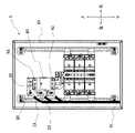
20 バーホルダ
21 入線端子部
22 仕切部
23 挿通孔
30 リードバー
80 主幹ブレーカ
81 一次側端子
82 二次側端子
Claims (2)
- 上部に一次側端子、下部に二次側端子を有する主幹ブレーカを備え、前記主幹ブレーカに系統電源からの入線が行われる配電盤であって、主幹ブレーカに隣接するように配置されたバーホルダに、主幹ブレーカの側方に系統からの入線が行われる入線端子部を備え、主幹ブレーカの一次側端子と入線端子部をつなぐリードバーを備え、入線端子部間を隔てる仕切部を主幹ブレーカに対して斜めに形成し、バーホルダの仕切部にリードバーを通す挿通孔を備えた配電盤。
- 入線端子部同士を奥行き方向にずらして配置した請求項1に記載の配電盤。
Priority Applications (1)
| Application Number | Priority Date | Filing Date | Title |
|---|---|---|---|
| JP2018208548A JP7154702B2 (ja) | 2018-11-06 | 2018-11-06 | 配電盤 |
Applications Claiming Priority (1)
| Application Number | Priority Date | Filing Date | Title |
|---|---|---|---|
| JP2018208548A JP7154702B2 (ja) | 2018-11-06 | 2018-11-06 | 配電盤 |
Publications (2)
| Publication Number | Publication Date |
|---|---|
| JP2020078120A JP2020078120A (ja) | 2020-05-21 |
| JP7154702B2 true JP7154702B2 (ja) | 2022-10-18 |
Family
ID=70724563
Family Applications (1)
| Application Number | Title | Priority Date | Filing Date |
|---|---|---|---|
| JP2018208548A Active JP7154702B2 (ja) | 2018-11-06 | 2018-11-06 | 配電盤 |
Country Status (1)
| Country | Link |
|---|---|
| JP (1) | JP7154702B2 (ja) |
Families Citing this family (2)
| Publication number | Priority date | Publication date | Assignee | Title |
|---|---|---|---|---|
| JP7491580B2 (ja) * | 2021-06-11 | 2024-05-28 | テンパール工業株式会社 | 切替開閉器内蔵盤 |
| US20240283284A1 (en) * | 2021-06-11 | 2024-08-22 | Tempearl Industrial Co., Ltd. | Changeover switch built-in board |
Citations (4)
| Publication number | Priority date | Publication date | Assignee | Title |
|---|---|---|---|---|
| JP2000188805A (ja) | 1998-12-21 | 2000-07-04 | Fuji Electric Co Ltd | 分電盤の接続導体装置 |
| JP2004166385A (ja) | 2002-11-12 | 2004-06-10 | Tempearl Ind Co Ltd | 分電盤 |
| JP2010022080A (ja) | 2008-07-08 | 2010-01-28 | Nitto Electric Works Ltd | 下側入線用分電盤 |
| JP2012135115A (ja) | 2010-12-21 | 2012-07-12 | Panasonic Eco Solutions Switchgear Devices Co Ltd | 分電盤 |
-
2018
- 2018-11-06 JP JP2018208548A patent/JP7154702B2/ja active Active
Patent Citations (4)
| Publication number | Priority date | Publication date | Assignee | Title |
|---|---|---|---|---|
| JP2000188805A (ja) | 1998-12-21 | 2000-07-04 | Fuji Electric Co Ltd | 分電盤の接続導体装置 |
| JP2004166385A (ja) | 2002-11-12 | 2004-06-10 | Tempearl Ind Co Ltd | 分電盤 |
| JP2010022080A (ja) | 2008-07-08 | 2010-01-28 | Nitto Electric Works Ltd | 下側入線用分電盤 |
| JP2012135115A (ja) | 2010-12-21 | 2012-07-12 | Panasonic Eco Solutions Switchgear Devices Co Ltd | 分電盤 |
Also Published As
| Publication number | Publication date |
|---|---|
| JP2020078120A (ja) | 2020-05-21 |
Similar Documents
| Publication | Publication Date | Title |
|---|---|---|
| JP6599404B2 (ja) | クランプ及びバスバーモジュール | |
| JP5105542B2 (ja) | 下側入線用分電盤 | |
| JP7154702B2 (ja) | 配電盤 | |
| JP6173579B2 (ja) | 母線構造およびこれを用いた配電盤 | |
| JP2019047579A (ja) | 配電盤 | |
| JP4979481B2 (ja) | 分電盤用バーホルダ | |
| CN106463920B (zh) | 开关装置 | |
| JP5081853B2 (ja) | 配電盤 | |
| JP5268863B2 (ja) | 電力用接続導体 | |
| JP5177744B2 (ja) | 分電盤 | |
| JP2009201313A (ja) | 分電盤用端子台および分電盤 | |
| JP2006238562A (ja) | プラグイン分電盤 | |
| JP4625385B2 (ja) | 配電盤 | |
| JPH10336807A (ja) | 配電盤 | |
| JP4364371B2 (ja) | 一次送り用端子台 | |
| JP4582691B2 (ja) | 配電盤 | |
| JP6996428B2 (ja) | 配電盤システム | |
| JP2008271710A (ja) | ブレーカユニット | |
| JP6858086B2 (ja) | 送り端子台 | |
| JP6334420B2 (ja) | 遮断器ユニット、遮断器用のベースユニット、及びスイッチギア | |
| JP7342368B2 (ja) | 端子盤用増設ユニット | |
| JP6433336B2 (ja) | 分電盤 | |
| JP4177304B2 (ja) | 電気接続箱の端子台接続構造 | |
| JP7545162B2 (ja) | 分電盤 | |
| JP6411053B2 (ja) | 接続構造 |
Legal Events
| Date | Code | Title | Description |
|---|---|---|---|
| A621 | Written request for application examination |
Free format text: JAPANESE INTERMEDIATE CODE: A621 Effective date: 20210921 |
|
| A977 | Report on retrieval |
Free format text: JAPANESE INTERMEDIATE CODE: A971007 Effective date: 20220525 |
|
| A131 | Notification of reasons for refusal |
Free format text: JAPANESE INTERMEDIATE CODE: A131 Effective date: 20220607 |
|
| A521 | Request for written amendment filed |
Free format text: JAPANESE INTERMEDIATE CODE: A523 Effective date: 20220726 |
|
| TRDD | Decision of grant or rejection written | ||
| A01 | Written decision to grant a patent or to grant a registration (utility model) |
Free format text: JAPANESE INTERMEDIATE CODE: A01 Effective date: 20221004 |
|
| A61 | First payment of annual fees (during grant procedure) |
Free format text: JAPANESE INTERMEDIATE CODE: A61 Effective date: 20221004 |
|
| R150 | Certificate of patent or registration of utility model |
Ref document number: 7154702 Country of ref document: JP Free format text: JAPANESE INTERMEDIATE CODE: R150 |