JP6147992B2 - Semiconductor device - Google Patents
Semiconductor device Download PDFInfo
- Publication number
- JP6147992B2 JP6147992B2 JP2012255559A JP2012255559A JP6147992B2 JP 6147992 B2 JP6147992 B2 JP 6147992B2 JP 2012255559 A JP2012255559 A JP 2012255559A JP 2012255559 A JP2012255559 A JP 2012255559A JP 6147992 B2 JP6147992 B2 JP 6147992B2
- Authority
- JP
- Japan
- Prior art keywords
- transistor
- oxide semiconductor
- semiconductor layer
- source
- drain
- Prior art date
- Legal status (The legal status is an assumption and is not a legal conclusion. Google has not performed a legal analysis and makes no representation as to the accuracy of the status listed.)
- Expired - Fee Related
Links
- 239000004065 semiconductor Substances 0.000 title claims description 91
- 239000011701 zinc Substances 0.000 description 24
- 239000000758 substrate Substances 0.000 description 20
- QVGXLLKOCUKJST-UHFFFAOYSA-N atomic oxygen Chemical compound [O] QVGXLLKOCUKJST-UHFFFAOYSA-N 0.000 description 19
- 239000001301 oxygen Substances 0.000 description 19
- 229910052760 oxygen Inorganic materials 0.000 description 19
- IJGRMHOSHXDMSA-UHFFFAOYSA-N Atomic nitrogen Chemical compound N#N IJGRMHOSHXDMSA-UHFFFAOYSA-N 0.000 description 15
- 239000013078 crystal Substances 0.000 description 14
- 125000004429 atom Chemical group 0.000 description 13
- 230000003071 parasitic effect Effects 0.000 description 12
- XUIMIQQOPSSXEZ-UHFFFAOYSA-N Silicon Chemical compound [Si] XUIMIQQOPSSXEZ-UHFFFAOYSA-N 0.000 description 10
- 229910052710 silicon Inorganic materials 0.000 description 10
- 239000010703 silicon Substances 0.000 description 10
- 238000010438 heat treatment Methods 0.000 description 9
- 239000004973 liquid crystal related substance Substances 0.000 description 9
- UFHFLCQGNIYNRP-UHFFFAOYSA-N Hydrogen Chemical compound [H][H] UFHFLCQGNIYNRP-UHFFFAOYSA-N 0.000 description 8
- 239000000460 chlorine Substances 0.000 description 8
- 239000001257 hydrogen Substances 0.000 description 8
- 229910052739 hydrogen Inorganic materials 0.000 description 8
- 239000010936 titanium Substances 0.000 description 8
- 230000015572 biosynthetic process Effects 0.000 description 7
- 230000000052 comparative effect Effects 0.000 description 7
- 229910052738 indium Inorganic materials 0.000 description 7
- 229910052782 aluminium Inorganic materials 0.000 description 6
- XAGFODPZIPBFFR-UHFFFAOYSA-N aluminium Chemical compound [Al] XAGFODPZIPBFFR-UHFFFAOYSA-N 0.000 description 6
- 239000003990 capacitor Substances 0.000 description 6
- 239000010949 copper Substances 0.000 description 6
- 238000010586 diagram Methods 0.000 description 6
- 239000012535 impurity Substances 0.000 description 6
- 238000000034 method Methods 0.000 description 6
- 229910052733 gallium Inorganic materials 0.000 description 5
- 238000004519 manufacturing process Methods 0.000 description 5
- 239000000463 material Substances 0.000 description 5
- 229910052751 metal Inorganic materials 0.000 description 5
- 229910044991 metal oxide Inorganic materials 0.000 description 5
- 150000004706 metal oxides Chemical class 0.000 description 5
- 229910052757 nitrogen Inorganic materials 0.000 description 5
- ZAMOUSCENKQFHK-UHFFFAOYSA-N Chlorine atom Chemical compound [Cl] ZAMOUSCENKQFHK-UHFFFAOYSA-N 0.000 description 4
- RTAQQCXQSZGOHL-UHFFFAOYSA-N Titanium Chemical compound [Ti] RTAQQCXQSZGOHL-UHFFFAOYSA-N 0.000 description 4
- XLOMVQKBTHCTTD-UHFFFAOYSA-N Zinc monoxide Chemical compound [Zn]=O XLOMVQKBTHCTTD-UHFFFAOYSA-N 0.000 description 4
- NIXOWILDQLNWCW-UHFFFAOYSA-N acrylic acid group Chemical group C(C=C)(=O)O NIXOWILDQLNWCW-UHFFFAOYSA-N 0.000 description 4
- 229910052801 chlorine Inorganic materials 0.000 description 4
- APFVFJFRJDLVQX-UHFFFAOYSA-N indium atom Chemical compound [In] APFVFJFRJDLVQX-UHFFFAOYSA-N 0.000 description 4
- 239000011159 matrix material Substances 0.000 description 4
- 239000002184 metal Substances 0.000 description 4
- 230000004048 modification Effects 0.000 description 4
- 238000012986 modification Methods 0.000 description 4
- 238000004544 sputter deposition Methods 0.000 description 4
- 229910052719 titanium Inorganic materials 0.000 description 4
- RYGMFSIKBFXOCR-UHFFFAOYSA-N Copper Chemical compound [Cu] RYGMFSIKBFXOCR-UHFFFAOYSA-N 0.000 description 3
- KRHYYFGTRYWZRS-UHFFFAOYSA-N Fluorane Chemical compound F KRHYYFGTRYWZRS-UHFFFAOYSA-N 0.000 description 3
- 229910052581 Si3N4 Inorganic materials 0.000 description 3
- 239000004020 conductor Substances 0.000 description 3
- 229910052802 copper Inorganic materials 0.000 description 3
- 238000005401 electroluminescence Methods 0.000 description 3
- 229910003437 indium oxide Inorganic materials 0.000 description 3
- PJXISJQVUVHSOJ-UHFFFAOYSA-N indium(iii) oxide Chemical compound [O-2].[O-2].[O-2].[In+3].[In+3] PJXISJQVUVHSOJ-UHFFFAOYSA-N 0.000 description 3
- 239000012212 insulator Substances 0.000 description 3
- 238000009832 plasma treatment Methods 0.000 description 3
- HQVNEWCFYHHQES-UHFFFAOYSA-N silicon nitride Chemical compound N12[Si]34N5[Si]62N3[Si]51N64 HQVNEWCFYHHQES-UHFFFAOYSA-N 0.000 description 3
- JBQYATWDVHIOAR-UHFFFAOYSA-N tellanylidenegermanium Chemical compound [Te]=[Ge] JBQYATWDVHIOAR-UHFFFAOYSA-N 0.000 description 3
- WFKWXMTUELFFGS-UHFFFAOYSA-N tungsten Chemical compound [W] WFKWXMTUELFFGS-UHFFFAOYSA-N 0.000 description 3
- 229910052721 tungsten Inorganic materials 0.000 description 3
- 239000010937 tungsten Substances 0.000 description 3
- 229910052725 zinc Inorganic materials 0.000 description 3
- 229910018120 Al-Ga-Zn Inorganic materials 0.000 description 2
- 229910018137 Al-Zn Inorganic materials 0.000 description 2
- 229910018573 Al—Zn Inorganic materials 0.000 description 2
- ZOXJGFHDIHLPTG-UHFFFAOYSA-N Boron Chemical compound [B] ZOXJGFHDIHLPTG-UHFFFAOYSA-N 0.000 description 2
- PXGOKWXKJXAPGV-UHFFFAOYSA-N Fluorine Chemical compound FF PXGOKWXKJXAPGV-UHFFFAOYSA-N 0.000 description 2
- GYHNNYVSQQEPJS-UHFFFAOYSA-N Gallium Chemical compound [Ga] GYHNNYVSQQEPJS-UHFFFAOYSA-N 0.000 description 2
- 229910052779 Neodymium Inorganic materials 0.000 description 2
- GQPLMRYTRLFLPF-UHFFFAOYSA-N Nitrous Oxide Chemical compound [O-][N+]#N GQPLMRYTRLFLPF-UHFFFAOYSA-N 0.000 description 2
- 229910020833 Sn-Al-Zn Inorganic materials 0.000 description 2
- 229910020868 Sn-Ga-Zn Inorganic materials 0.000 description 2
- 229910020994 Sn-Zn Inorganic materials 0.000 description 2
- 229910009069 Sn—Zn Inorganic materials 0.000 description 2
- ATJFFYVFTNAWJD-UHFFFAOYSA-N Tin Chemical compound [Sn] ATJFFYVFTNAWJD-UHFFFAOYSA-N 0.000 description 2
- UMVBXBACMIOFDO-UHFFFAOYSA-N [N].[Si] Chemical compound [N].[Si] UMVBXBACMIOFDO-UHFFFAOYSA-N 0.000 description 2
- 229910052796 boron Inorganic materials 0.000 description 2
- 239000011651 chromium Substances 0.000 description 2
- 229910052731 fluorine Inorganic materials 0.000 description 2
- 239000011737 fluorine Substances 0.000 description 2
- 239000000203 mixture Substances 0.000 description 2
- QEFYFXOXNSNQGX-UHFFFAOYSA-N neodymium atom Chemical compound [Nd] QEFYFXOXNSNQGX-UHFFFAOYSA-N 0.000 description 2
- 238000005268 plasma chemical vapour deposition Methods 0.000 description 2
- VYPSYNLAJGMNEJ-UHFFFAOYSA-N silicon dioxide Inorganic materials O=[Si]=O VYPSYNLAJGMNEJ-UHFFFAOYSA-N 0.000 description 2
- 239000003381 stabilizer Substances 0.000 description 2
- XOLBLPGZBRYERU-UHFFFAOYSA-N tin dioxide Chemical compound O=[Sn]=O XOLBLPGZBRYERU-UHFFFAOYSA-N 0.000 description 2
- 229910001887 tin oxide Inorganic materials 0.000 description 2
- 239000011787 zinc oxide Substances 0.000 description 2
- 229910052684 Cerium Inorganic materials 0.000 description 1
- VYZAMTAEIAYCRO-UHFFFAOYSA-N Chromium Chemical compound [Cr] VYZAMTAEIAYCRO-UHFFFAOYSA-N 0.000 description 1
- 229910052692 Dysprosium Inorganic materials 0.000 description 1
- 229910052691 Erbium Inorganic materials 0.000 description 1
- 229910052693 Europium Inorganic materials 0.000 description 1
- 229910052688 Gadolinium Inorganic materials 0.000 description 1
- 229910052689 Holmium Inorganic materials 0.000 description 1
- 229910052765 Lutetium Inorganic materials 0.000 description 1
- ZOKXTWBITQBERF-UHFFFAOYSA-N Molybdenum Chemical compound [Mo] ZOKXTWBITQBERF-UHFFFAOYSA-N 0.000 description 1
- 229910052777 Praseodymium Inorganic materials 0.000 description 1
- 229910052772 Samarium Inorganic materials 0.000 description 1
- 229910020944 Sn-Mg Inorganic materials 0.000 description 1
- 229910052771 Terbium Inorganic materials 0.000 description 1
- 229910052775 Thulium Inorganic materials 0.000 description 1
- 229910052769 Ytterbium Inorganic materials 0.000 description 1
- 229910009369 Zn Mg Inorganic materials 0.000 description 1
- 229910007573 Zn-Mg Inorganic materials 0.000 description 1
- 239000002253 acid Substances 0.000 description 1
- 239000000956 alloy Substances 0.000 description 1
- 229910045601 alloy Inorganic materials 0.000 description 1
- 230000005540 biological transmission Effects 0.000 description 1
- 239000000919 ceramic Substances 0.000 description 1
- GWXLDORMOJMVQZ-UHFFFAOYSA-N cerium Chemical compound [Ce] GWXLDORMOJMVQZ-UHFFFAOYSA-N 0.000 description 1
- 238000005229 chemical vapour deposition Methods 0.000 description 1
- 229910052804 chromium Inorganic materials 0.000 description 1
- 239000000470 constituent Substances 0.000 description 1
- 238000002425 crystallisation Methods 0.000 description 1
- 230000008025 crystallization Effects 0.000 description 1
- 238000003795 desorption Methods 0.000 description 1
- KBQHZAAAGSGFKK-UHFFFAOYSA-N dysprosium atom Chemical compound [Dy] KBQHZAAAGSGFKK-UHFFFAOYSA-N 0.000 description 1
- 230000000694 effects Effects 0.000 description 1
- UYAHIZSMUZPPFV-UHFFFAOYSA-N erbium Chemical compound [Er] UYAHIZSMUZPPFV-UHFFFAOYSA-N 0.000 description 1
- OGPBJKLSAFTDLK-UHFFFAOYSA-N europium atom Chemical compound [Eu] OGPBJKLSAFTDLK-UHFFFAOYSA-N 0.000 description 1
- UIWYJDYFSGRHKR-UHFFFAOYSA-N gadolinium atom Chemical compound [Gd] UIWYJDYFSGRHKR-UHFFFAOYSA-N 0.000 description 1
- 239000011521 glass Substances 0.000 description 1
- 229910052735 hafnium Inorganic materials 0.000 description 1
- VBJZVLUMGGDVMO-UHFFFAOYSA-N hafnium atom Chemical compound [Hf] VBJZVLUMGGDVMO-UHFFFAOYSA-N 0.000 description 1
- KJZYNXUDTRRSPN-UHFFFAOYSA-N holmium atom Chemical compound [Ho] KJZYNXUDTRRSPN-UHFFFAOYSA-N 0.000 description 1
- 229910052747 lanthanoid Inorganic materials 0.000 description 1
- 150000002602 lanthanoids Chemical class 0.000 description 1
- 229910052746 lanthanum Inorganic materials 0.000 description 1
- FZLIPJUXYLNCLC-UHFFFAOYSA-N lanthanum atom Chemical compound [La] FZLIPJUXYLNCLC-UHFFFAOYSA-N 0.000 description 1
- OHSVLFRHMCKCQY-UHFFFAOYSA-N lutetium atom Chemical compound [Lu] OHSVLFRHMCKCQY-UHFFFAOYSA-N 0.000 description 1
- 239000012528 membrane Substances 0.000 description 1
- 229910052750 molybdenum Inorganic materials 0.000 description 1
- 239000011733 molybdenum Substances 0.000 description 1
- 150000004767 nitrides Chemical class 0.000 description 1
- QJGQUHMNIGDVPM-UHFFFAOYSA-N nitrogen group Chemical group [N] QJGQUHMNIGDVPM-UHFFFAOYSA-N 0.000 description 1
- 239000001272 nitrous oxide Substances 0.000 description 1
- QGLKJKCYBOYXKC-UHFFFAOYSA-N nonaoxidotritungsten Chemical compound O=[W]1(=O)O[W](=O)(=O)O[W](=O)(=O)O1 QGLKJKCYBOYXKC-UHFFFAOYSA-N 0.000 description 1
- TWNQGVIAIRXVLR-UHFFFAOYSA-N oxo(oxoalumanyloxy)alumane Chemical compound O=[Al]O[Al]=O TWNQGVIAIRXVLR-UHFFFAOYSA-N 0.000 description 1
- 125000004430 oxygen atom Chemical group O* 0.000 description 1
- BPUBBGLMJRNUCC-UHFFFAOYSA-N oxygen(2-);tantalum(5+) Chemical compound [O-2].[O-2].[O-2].[O-2].[O-2].[Ta+5].[Ta+5] BPUBBGLMJRNUCC-UHFFFAOYSA-N 0.000 description 1
- 238000000206 photolithography Methods 0.000 description 1
- PUDIUYLPXJFUGB-UHFFFAOYSA-N praseodymium atom Chemical compound [Pr] PUDIUYLPXJFUGB-UHFFFAOYSA-N 0.000 description 1
- 239000010453 quartz Substances 0.000 description 1
- KZUNJOHGWZRPMI-UHFFFAOYSA-N samarium atom Chemical compound [Sm] KZUNJOHGWZRPMI-UHFFFAOYSA-N 0.000 description 1
- 229910052594 sapphire Inorganic materials 0.000 description 1
- 239000010980 sapphire Substances 0.000 description 1
- 229910052706 scandium Inorganic materials 0.000 description 1
- SIXSYDAISGFNSX-UHFFFAOYSA-N scandium atom Chemical compound [Sc] SIXSYDAISGFNSX-UHFFFAOYSA-N 0.000 description 1
- 238000001004 secondary ion mass spectrometry Methods 0.000 description 1
- VSZWPYCFIRKVQL-UHFFFAOYSA-N selanylidenegallium;selenium Chemical compound [Se].[Se]=[Ga].[Se]=[Ga] VSZWPYCFIRKVQL-UHFFFAOYSA-N 0.000 description 1
- LIVNPJMFVYWSIS-UHFFFAOYSA-N silicon monoxide Chemical compound [Si-]#[O+] LIVNPJMFVYWSIS-UHFFFAOYSA-N 0.000 description 1
- 229910052814 silicon oxide Inorganic materials 0.000 description 1
- 229910052715 tantalum Inorganic materials 0.000 description 1
- GUVRBAGPIYLISA-UHFFFAOYSA-N tantalum atom Chemical compound [Ta] GUVRBAGPIYLISA-UHFFFAOYSA-N 0.000 description 1
- 229910001936 tantalum oxide Inorganic materials 0.000 description 1
- GZCRRIHWUXGPOV-UHFFFAOYSA-N terbium atom Chemical compound [Tb] GZCRRIHWUXGPOV-UHFFFAOYSA-N 0.000 description 1
- FRNOGLGSGLTDKL-UHFFFAOYSA-N thulium atom Chemical compound [Tm] FRNOGLGSGLTDKL-UHFFFAOYSA-N 0.000 description 1
- 229910001930 tungsten oxide Inorganic materials 0.000 description 1
- NAWDYIZEMPQZHO-UHFFFAOYSA-N ytterbium Chemical compound [Yb] NAWDYIZEMPQZHO-UHFFFAOYSA-N 0.000 description 1
Images


Classifications
-
- H—ELECTRICITY
- H01—ELECTRIC ELEMENTS
- H01L—SEMICONDUCTOR DEVICES NOT COVERED BY CLASS H10
- H01L29/00—Semiconductor devices adapted for rectifying, amplifying, oscillating or switching, or capacitors or resistors with at least one potential-jump barrier or surface barrier, e.g. PN junction depletion layer or carrier concentration layer; Details of semiconductor bodies or of electrodes thereof ; Multistep manufacturing processes therefor
- H01L29/66—Types of semiconductor device ; Multistep manufacturing processes therefor
- H01L29/68—Types of semiconductor device ; Multistep manufacturing processes therefor controllable by only the electric current supplied, or only the electric potential applied, to an electrode which does not carry the current to be rectified, amplified or switched
- H01L29/76—Unipolar devices, e.g. field effect transistors
- H01L29/772—Field effect transistors
- H01L29/78—Field effect transistors with field effect produced by an insulated gate
- H01L29/786—Thin film transistors, i.e. transistors with a channel being at least partly a thin film
- H01L29/7869—Thin film transistors, i.e. transistors with a channel being at least partly a thin film having a semiconductor body comprising an oxide semiconductor material, e.g. zinc oxide, copper aluminium oxide, cadmium stannate
-
- H—ELECTRICITY
- H01—ELECTRIC ELEMENTS
- H01L—SEMICONDUCTOR DEVICES NOT COVERED BY CLASS H10
- H01L29/00—Semiconductor devices adapted for rectifying, amplifying, oscillating or switching, or capacitors or resistors with at least one potential-jump barrier or surface barrier, e.g. PN junction depletion layer or carrier concentration layer; Details of semiconductor bodies or of electrodes thereof ; Multistep manufacturing processes therefor
- H01L29/02—Semiconductor bodies ; Multistep manufacturing processes therefor
- H01L29/06—Semiconductor bodies ; Multistep manufacturing processes therefor characterised by their shape; characterised by the shapes, relative sizes, or dispositions of the semiconductor regions ; characterised by the concentration or distribution of impurities within semiconductor regions
- H01L29/10—Semiconductor bodies ; Multistep manufacturing processes therefor characterised by their shape; characterised by the shapes, relative sizes, or dispositions of the semiconductor regions ; characterised by the concentration or distribution of impurities within semiconductor regions with semiconductor regions connected to an electrode not carrying current to be rectified, amplified or switched and such electrode being part of a semiconductor device which comprises three or more electrodes
- H01L29/1025—Channel region of field-effect devices
- H01L29/1029—Channel region of field-effect devices of field-effect transistors
- H01L29/1033—Channel region of field-effect devices of field-effect transistors with insulated gate, e.g. characterised by the length, the width, the geometric contour or the doping structure
-
- H—ELECTRICITY
- H01—ELECTRIC ELEMENTS
- H01L—SEMICONDUCTOR DEVICES NOT COVERED BY CLASS H10
- H01L29/00—Semiconductor devices adapted for rectifying, amplifying, oscillating or switching, or capacitors or resistors with at least one potential-jump barrier or surface barrier, e.g. PN junction depletion layer or carrier concentration layer; Details of semiconductor bodies or of electrodes thereof ; Multistep manufacturing processes therefor
- H01L29/40—Electrodes ; Multistep manufacturing processes therefor
- H01L29/41—Electrodes ; Multistep manufacturing processes therefor characterised by their shape, relative sizes or dispositions
- H01L29/417—Electrodes ; Multistep manufacturing processes therefor characterised by their shape, relative sizes or dispositions carrying the current to be rectified, amplified or switched
- H01L29/41725—Source or drain electrodes for field effect devices
- H01L29/41733—Source or drain electrodes for field effect devices for thin film transistors with insulated gate
-
- H—ELECTRICITY
- H01—ELECTRIC ELEMENTS
- H01L—SEMICONDUCTOR DEVICES NOT COVERED BY CLASS H10
- H01L29/00—Semiconductor devices adapted for rectifying, amplifying, oscillating or switching, or capacitors or resistors with at least one potential-jump barrier or surface barrier, e.g. PN junction depletion layer or carrier concentration layer; Details of semiconductor bodies or of electrodes thereof ; Multistep manufacturing processes therefor
- H01L29/40—Electrodes ; Multistep manufacturing processes therefor
- H01L29/41—Electrodes ; Multistep manufacturing processes therefor characterised by their shape, relative sizes or dispositions
- H01L29/423—Electrodes ; Multistep manufacturing processes therefor characterised by their shape, relative sizes or dispositions not carrying the current to be rectified, amplified or switched
- H01L29/42312—Gate electrodes for field effect devices
- H01L29/42316—Gate electrodes for field effect devices for field-effect transistors
- H01L29/4232—Gate electrodes for field effect devices for field-effect transistors with insulated gate
- H01L29/42384—Gate electrodes for field effect devices for field-effect transistors with insulated gate for thin film field effect transistors, e.g. characterised by the thickness or the shape of the insulator or the dimensions, the shape or the lay-out of the conductor
-
- H—ELECTRICITY
- H01—ELECTRIC ELEMENTS
- H01L—SEMICONDUCTOR DEVICES NOT COVERED BY CLASS H10
- H01L29/00—Semiconductor devices adapted for rectifying, amplifying, oscillating or switching, or capacitors or resistors with at least one potential-jump barrier or surface barrier, e.g. PN junction depletion layer or carrier concentration layer; Details of semiconductor bodies or of electrodes thereof ; Multistep manufacturing processes therefor
- H01L29/66—Types of semiconductor device ; Multistep manufacturing processes therefor
- H01L29/68—Types of semiconductor device ; Multistep manufacturing processes therefor controllable by only the electric current supplied, or only the electric potential applied, to an electrode which does not carry the current to be rectified, amplified or switched
- H01L29/76—Unipolar devices, e.g. field effect transistors
- H01L29/772—Field effect transistors
- H01L29/78—Field effect transistors with field effect produced by an insulated gate
- H01L29/786—Thin film transistors, i.e. transistors with a channel being at least partly a thin film
- H01L29/78606—Thin film transistors, i.e. transistors with a channel being at least partly a thin film with supplementary region or layer in the thin film or in the insulated bulk substrate supporting it for controlling or increasing the safety of the device
- H01L29/78618—Thin film transistors, i.e. transistors with a channel being at least partly a thin film with supplementary region or layer in the thin film or in the insulated bulk substrate supporting it for controlling or increasing the safety of the device characterised by the drain or the source properties, e.g. the doping structure, the composition, the sectional shape or the contact structure
-
- H—ELECTRICITY
- H01—ELECTRIC ELEMENTS
- H01L—SEMICONDUCTOR DEVICES NOT COVERED BY CLASS H10
- H01L29/00—Semiconductor devices adapted for rectifying, amplifying, oscillating or switching, or capacitors or resistors with at least one potential-jump barrier or surface barrier, e.g. PN junction depletion layer or carrier concentration layer; Details of semiconductor bodies or of electrodes thereof ; Multistep manufacturing processes therefor
- H01L29/66—Types of semiconductor device ; Multistep manufacturing processes therefor
- H01L29/68—Types of semiconductor device ; Multistep manufacturing processes therefor controllable by only the electric current supplied, or only the electric potential applied, to an electrode which does not carry the current to be rectified, amplified or switched
- H01L29/76—Unipolar devices, e.g. field effect transistors
- H01L29/772—Field effect transistors
- H01L29/78—Field effect transistors with field effect produced by an insulated gate
- H01L29/786—Thin film transistors, i.e. transistors with a channel being at least partly a thin film
- H01L29/7869—Thin film transistors, i.e. transistors with a channel being at least partly a thin film having a semiconductor body comprising an oxide semiconductor material, e.g. zinc oxide, copper aluminium oxide, cadmium stannate
- H01L29/78693—Thin film transistors, i.e. transistors with a channel being at least partly a thin film having a semiconductor body comprising an oxide semiconductor material, e.g. zinc oxide, copper aluminium oxide, cadmium stannate the semiconducting oxide being amorphous
-
- H—ELECTRICITY
- H01—ELECTRIC ELEMENTS
- H01L—SEMICONDUCTOR DEVICES NOT COVERED BY CLASS H10
- H01L29/00—Semiconductor devices adapted for rectifying, amplifying, oscillating or switching, or capacitors or resistors with at least one potential-jump barrier or surface barrier, e.g. PN junction depletion layer or carrier concentration layer; Details of semiconductor bodies or of electrodes thereof ; Multistep manufacturing processes therefor
- H01L29/40—Electrodes ; Multistep manufacturing processes therefor
- H01L29/41—Electrodes ; Multistep manufacturing processes therefor characterised by their shape, relative sizes or dispositions
- H01L29/423—Electrodes ; Multistep manufacturing processes therefor characterised by their shape, relative sizes or dispositions not carrying the current to be rectified, amplified or switched
- H01L29/42312—Gate electrodes for field effect devices
- H01L29/42316—Gate electrodes for field effect devices for field-effect transistors
- H01L29/4232—Gate electrodes for field effect devices for field-effect transistors with insulated gate
- H01L29/42384—Gate electrodes for field effect devices for field-effect transistors with insulated gate for thin film field effect transistors, e.g. characterised by the thickness or the shape of the insulator or the dimensions, the shape or the lay-out of the conductor
- H01L2029/42388—Gate electrodes for field effect devices for field-effect transistors with insulated gate for thin film field effect transistors, e.g. characterised by the thickness or the shape of the insulator or the dimensions, the shape or the lay-out of the conductor characterised by the shape of the insulating material
Description
本発明は、トランジスタに関する。特に、チャネルが酸化物半導体層に形成されるトランジスタに関する。また、本発明は、当該トランジスタを有する半導体装置に関する。例えば、当該トランジスタを各画素に有するアクティブマトリクス型の表示装置に関する。なお、本明細書において半導体装置とは、半導体特性を利用して機能する全ての装置を指す。 The present invention relates to a transistor. In particular, the present invention relates to a transistor in which a channel is formed in an oxide semiconductor layer. The present invention also relates to a semiconductor device having the transistor. For example, the present invention relates to an active matrix display device including the transistor in each pixel. Note that in this specification, a semiconductor device refers to all devices that function by utilizing semiconductor characteristics.
近年、トランジスタの構成材料として、酸化物半導体と呼ばれる半導体特性を示す金属酸化物に注目が集まっている。金属酸化物は様々な用途に用いられている。例えば、酸化インジウムは、液晶表示装置において画素電極の材料として用いられている。半導体特性を示す金属酸化物としては、例えば、酸化タングステン、酸化錫、酸化インジウム、酸化亜鉛などがあり、このような半導体特性を示す金属酸化物層にチャネルが形成されるトランジスタが、既に知られている(特許文献1及び特許文献2)。 In recent years, attention has been focused on metal oxides having semiconductor characteristics called oxide semiconductors as constituent materials of transistors. Metal oxides are used in various applications. For example, indium oxide is used as a material for a pixel electrode in a liquid crystal display device. Examples of metal oxides that exhibit semiconductor characteristics include tungsten oxide, tin oxide, indium oxide, and zinc oxide. Transistors in which a channel is formed in a metal oxide layer that exhibits such semiconductor characteristics are already known. (Patent Document 1 and Patent Document 2).
酸化物半導体層にチャネルが形成されるトランジスタは、加工条件又は熱処理条件によって電気的特性が変化することがある。当該変化は、当該酸化物半導体層の形成工程時に低抵抗化元素(塩素(Cl)、フッ素(F)、硼素(B)、又は水素(H)など)が混入する、又は当該酸化物半導体層から酸素(O)が脱離することなどに起因するものと考えられる。そして、当該変化は、酸化物半導体層の端部において顕在化しやすいことが分かった。すなわち、酸化物半導体層にチャネルが形成されるトランジスタにおいては、当該酸化物半導体層の端部が低抵抗領域となり、当該領域にトランジスタの寄生チャネルが形成されやすいことが分かった。なお、当該トランジスタにおいては、ゲートとソース間の電圧に応じて形成されるチャネル(第1のチャネルともいう)と、当該寄生チャネル(第2のチャネルともいう)との2種のチャネルが形成されうることになる。 In a transistor in which a channel is formed in an oxide semiconductor layer, electrical characteristics may change depending on processing conditions or heat treatment conditions. The change is caused by a low-resistance element (chlorine (Cl), fluorine (F), boron (B), hydrogen (H), or the like) mixed in the oxide semiconductor layer formation step, or the oxide semiconductor layer. This is thought to be due to the desorption of oxygen (O) from the surface. And it turned out that the said change is easy to manifest in the edge part of an oxide semiconductor layer. That is, it was found that in a transistor in which a channel is formed in the oxide semiconductor layer, an end portion of the oxide semiconductor layer is a low-resistance region, and a parasitic channel of the transistor is easily formed in the region. Note that in this transistor, two types of channels are formed: a channel (also referred to as a first channel) formed in accordance with the voltage between the gate and the source, and the parasitic channel (also referred to as a second channel). It will be going.
2種のチャネルが形成されうるトランジスタにおいては、多くの場合、それぞれのチャネルが形成されるゲートとソース間のしきい値電圧が異なる。典型的には、第1のチャネルが形成されるしきい値電圧は、第2のチャネルが形成されるしきい値電圧よりも高い。そして、第1のチャネルの電流駆動能力は、第2のチャネルの電流駆動能力よりも高い。よって、オフ状態にある当該トランジスタのゲートとソース間の電圧を上昇させていった場合、ソースとドレイン間の電流が2段階の変化をすることになる。具体的には、第2のチャネルが形成されるしきい値電圧の近傍において1段階目の変化(ソースとドレイン間の電流の増加)が確認され、さらに、第1のチャネルが形成されるしきい値電圧の近傍において2段階目の変化(ソースとドレイン間の電流の増加)が確認される。 In a transistor in which two types of channels can be formed, in many cases, the threshold voltage between the gate and the source in which each channel is formed is different. Typically, the threshold voltage at which the first channel is formed is higher than the threshold voltage at which the second channel is formed. The current drive capability of the first channel is higher than the current drive capability of the second channel. Therefore, when the voltage between the gate and the source of the transistor in the off state is increased, the current between the source and the drain changes in two steps. Specifically, a first-stage change (increase in current between the source and drain) is confirmed in the vicinity of the threshold voltage at which the second channel is formed, and further, the first channel is formed. A second-stage change (increase in current between the source and drain) is confirmed in the vicinity of the threshold voltage.
デジタル回路において、トランジスタはスイッチとして活用されている。当該スイッチとして2段階の変化をする素子が好ましくないことは言うまでもない。この点に鑑み、本発明の一態様では、酸化物半導体層にチャネルが形成されるトランジスタのスイッチング特性を改善することを目的の一とする。 In digital circuits, transistors are used as switches. Needless to say, an element that changes in two stages is not preferable as the switch. In view of this point, an object of one embodiment of the present invention is to improve switching characteristics of a transistor in which a channel is formed in an oxide semiconductor layer.
酸化物半導体層の端部に寄生チャネルが形成されるのは、当該端部と電気的に接続されるトランジスタのソース及びドレインが存在するからである。すなわち、当該端部とトランジスタのソース及びドレインの少なくとも一方が電気的に接続されていなければ当該端部に寄生チャネルは形成されない。よって、本発明の一態様は、トランジスタのソース及びドレインの少なくとも一方と、酸化物半導体層の端部とが電気的に接続されない又は接続される蓋然性を低減することが可能な構造のトランジスタを提供することを要旨とする。 The parasitic channel is formed at the end portion of the oxide semiconductor layer because the source and the drain of the transistor electrically connected to the end portion exist. That is, a parasitic channel is not formed at the end unless the end and at least one of the source and the drain of the transistor are electrically connected. Thus, one embodiment of the present invention provides a transistor having a structure in which at least one of a source and a drain of a transistor and an end portion of an oxide semiconductor layer are not electrically connected or the probability of being connected is reduced. The gist is to do.
例えば、本発明の一態様は、トランジスタのソース及びドレインの少なくとも一方が酸化物半導体層の端部と接していないトランジスタである。さらに、本発明の一態様においては、酸化物半導体層の端部と接していないソース及びドレインの少なくとも一方と酸化物半導体層の端部間の距離が、ソースとドレイン間の距離よりも長い構成とすることが好ましい。 For example, one embodiment of the present invention is a transistor in which at least one of a source and a drain of the transistor is not in contact with an end portion of the oxide semiconductor layer. Further, according to one embodiment of the present invention, the distance between at least one of the source and the drain that is not in contact with the end portion of the oxide semiconductor layer and the end portion of the oxide semiconductor layer is longer than the distance between the source and the drain. It is preferable that
本発明の一態様のトランジスタにおいては、トランジスタのソース及びドレインが酸化物半導体層の端部を介して電気的に接続されない又は接続される(当該端部に寄生チャネルが形成される)蓋然性を低減することが可能である。よって、当該トランジスタにおいては、ゲートとソース間の電圧に応じてソースとドレイン間の電流が2段階に変化することがない又は変化する蓋然性を低減することが可能である。すなわち、本発明の一態様においては、酸化物半導体層にチャネルが形成されるトランジスタのスイッチング特性を改善することが可能である。 In the transistor of one embodiment of the present invention, the probability that the source and the drain of the transistor are not electrically connected or connected through the end portion of the oxide semiconductor layer (a parasitic channel is formed at the end portion) is reduced. Is possible. Therefore, in the transistor, the probability that the current between the source and the drain does not change in two stages or changes depending on the voltage between the gate and the source can be reduced. That is, in one embodiment of the present invention, switching characteristics of a transistor in which a channel is formed in an oxide semiconductor layer can be improved.
以下では、本発明の一態様について詳細に説明する。ただし、本発明は以下の説明に限定されず、本発明の趣旨およびその範囲から逸脱することなくその形態を様々に変更し得る。したがって、本発明は以下に示す記載内容に限定して解釈されるものではない。 Hereinafter, one embodiment of the present invention will be described in detail. However, the present invention is not limited to the following description, and various modifications can be made without departing from the spirit and scope of the present invention. Therefore, the present invention should not be interpreted as being limited to the description below.
<トランジスタの構造例>
本発明の一態様に係るトランジスタの構造について図1を参照して説明する。図1(A)は、本発明の一態様に係るトランジスタの平面図であり、図1(B)は、図1(A)に示す平面図中のA−B線における断面図である。
<Example of transistor structure>
A structure of a transistor according to one embodiment of the present invention is described with reference to FIGS. FIG. 1A is a plan view of a transistor according to one embodiment of the present invention, and FIG. 1B is a cross-sectional view taken along line AB in the plan view of FIG.
図1(A)、(B)に示すトランジスタは、絶縁表面を有する基板10上に設けられたゲート11と、ゲート11上に設けられたゲート絶縁層12と、ゲート絶縁層12を介してゲート11と重畳する酸化物半導体層13と、酸化物半導体層13上のソース14及びドレイン15とを有する。さらに、当該トランジスタ上には、絶縁層16と、絶縁層16に設けられた開口部においてドレイン15と接する導電層17とが設けられている。なお、ソース14及びドレイン15は、置換することが可能である。すなわち、本発明の一態様は、図1(A)、(B)に示すようにドレイン15がソース14に囲まれる構成に限定されず、ソースがドレインに囲まれる構成とすることも可能である。
1A and 1B includes a
図1(A)、(B)に示すトランジスタにおいては、ソース14と接触する領域における酸化物半導体層13及びドレイン15と接触する領域における酸化物半導体層13の少なくとも一方に含まれる低抵抗化元素の濃度が、酸化物半導体層13の端部に含まれる当該低抵抗化元素の濃度よりも低くなることがある。なお、当該低抵抗化元素としては、塩素(Cl)、フッ素(F)、硼素(B)、水素(H)などが挙げられる。
In the transistor illustrated in FIGS. 1A and 1B, a low-resistance element included in at least one of the
また、図1(A)、(B)に示すトランジスタにおいては、ソース14と接触する領域における酸化物半導体層13及びドレイン15と接触する領域における酸化物半導体層13の少なくとも一方に含まれる酸素の濃度が、酸化物半導体層13の端部に含まれる酸素の濃度よりも高くなることがある。
1A and 1B, oxygen contained in at least one of the
ただし、図1(A)、(B)に示すトランジスタにおいては、ソース14及びドレイン15の双方が酸化物半導体層13の端部に接することがない。具体的には、当該トランジスタにおいては、ソース14が開口部を有する円形状(内周及び外周が共に円状)であり、ドレイン15が当該開口部に存在する。よって、図1(A)、(B)に示すトランジスタにおいては、酸化物半導体層13の端部が低抵抗化した場合であっても当該端部に寄生チャネルが形成されることがない。その結果、図1(A)、(B)に示すトランジスタにおいては、寄生チャネルの存在に起因するスイッチング特性の劣化が生じない。
However, in the transistor illustrated in FIGS. 1A and 1B, both the
なお、このことは、ソース及びドレインの一方によってソース及びドレインの他方が囲まれている構造を有するトランジスタにおいて共通する。すなわち、ソース及びドレインの一方の内周及び外周が閉曲線若しくは多角形又は一部が曲線且つ残部が折れ線であり、且つソース及びドレインの他方がソース及びドレインの一方の内側に存在するトランジスタにおいては、酸化物半導体層13の端部が低抵抗化した場合であっても当該端部に寄生チャネルが形成されることがない。
Note that this is common in transistors having a structure in which the other of the source and the drain is surrounded by one of the source and the drain. That is, in the transistor in which the inner periphery and outer periphery of one of the source and the drain are a closed curve or a polygon, or a part is a curve and the rest is a broken line, and the other of the source and the drain exists inside one of the source and the drain, Even when the resistance of the end portion of the
(基板)
絶縁表面を有する基板10としては、後の熱処理に耐えうる程度の耐熱性を有している基板であればどのような基板を適用してもよい。例えば、ガラス基板、セラミック基板、石英基板、サファイア基板などの基板を用いることができる。また、基板10として、可撓性基板を用いてもよい。なお、基板10に含まれる元素が後に形成される酸化物半導体層に混入することを防ぐため、基板10上に絶縁層を形成することも可能である。
(substrate)
As the
(導電体)
ゲート11、ソース14、及びドレイン15、並びに導電層17としては、アルミニウム(Al)、銅(Cu)、チタン(Ti)、タンタル(Ta)、タングステン(W)、モリブデン(Mo)、クロム(Cr)、ネオジム(Nd)、スカンジウム(Sc)から選ばれた元素、上述した元素を成分とする合金、または上述した元素を成分とする窒化物を適用することができる。また、これらの材料の積層構造を適用することもできる。
(conductor)
As the
(絶縁体)
ゲート絶縁層12及び絶縁層16としては、酸化シリコン、窒化シリコン、酸化窒化シリコン、窒化酸化シリコン、酸化アルミニウム、酸化タンタルなどの絶縁体を適用することができる。また、これらの材料の積層構造を適用することもできる。なお、酸化窒化シリコンとは、その組成として、窒素よりも酸素の含有量が多いものであり、濃度範囲として酸素が55〜65原子%、窒素が1〜20原子%、シリコンが25〜35原子%、水素が0.1〜10原子%の範囲において、合計100原子%となるように各元素を任意の濃度で含むものをいう。また、窒化酸化シリコンとは、その組成として、酸素よりも窒素の含有量が多いものであり、濃度範囲として酸素が15〜30原子%、窒素が20〜35原子%、シリコンが25〜35原子%、水素が15〜25原子%の範囲において、合計100原子%となるように各元素を任意の濃度で含むものをいう。
(Insulator)
As the
(半導体)
酸化物半導体層13としては、少なくともインジウム(In)又は亜鉛(Zn)を含む酸化物を適用することができる。特に、インジウム(In)及び亜鉛(Zn)を含む酸化物を適用することが好ましい。また、酸化物半導体層13中の酸素欠損を減らすためのスタビライザーとして、酸化物半導体層13にガリウム(Ga)が含まれることが好ましい。また、酸化物半導体層13が、スタビライザーとして、スズ(Sn)、ハフニウム(Hf)、アルミニウム(Al)、若しくはジルコニウム(Zr)、又は、ランタノイドである、ランタン(La)、セリウム(Ce)、プラセオジム(Pr)、ネオジム(Nd)、サマリウム(Sm)、ユウロピウム(Eu)、ガドリニウム(Gd)、テルビウム(Tb)、ジスプロシウム(Dy)、ホルミウム(Ho)、エルビウム(Er)、ツリウム(Tm)、イッテルビウム(Yb)、若しくはルテチウム(Lu)のいずれか一種あるいは複数種を含む構成としてもよい。
(semiconductor)
As the
例えば、酸化物半導体層13としては、酸化インジウム、酸化スズ、若しくは酸化亜鉛、二元系金属の酸化物であるIn−Zn系酸化物、Sn−Zn系酸化物、Al−Zn系酸化物、Zn−Mg系酸化物、Sn−Mg系酸化物、In−Mg系酸化物、若しくはIn−Ga系酸化物、三元系金属の酸化物であるIn−Ga−Zn系酸化物、In−Al−Zn系酸化物、In−Sn−Zn系酸化物、Sn−Ga−Zn系酸化物、Al−Ga−Zn系酸化物、Sn−Al−Zn系酸化物、In−Hf−Zn系酸化物、In−La−Zn系酸化物、In−Ce−Zn系酸化物、In−Pr−Zn系酸化物、In−Nd−Zn系酸化物、In−Sm−Zn系酸化物、In−Eu−Zn系酸化物、In−Gd−Zn系酸化物、In−Tb−Zn系酸化物、In−Dy−Zn系酸化物、In−Ho−Zn系酸化物、In−Er−Zn系酸化物、In−Tm−Zn系酸化物、In−Yb−Zn系酸化物、若しくはIn−Lu−Zn系酸化物、又は四元系金属の酸化物であるIn−Sn−Ga−Zn系酸化物、In−Hf−Ga−Zn系酸化物、In−Al−Ga−Zn系酸化物、In−Sn−Al−Zn系酸化物、In−Sn−Hf−Zn系酸化物、若しくはIn−Hf−Al−Zn系酸化物を用いることができる。 For example, as the oxide semiconductor layer 13, indium oxide, tin oxide, or zinc oxide, a binary metal oxide In—Zn-based oxide, Sn—Zn-based oxide, Al—Zn-based oxide, Zn-Mg-based oxide, Sn-Mg-based oxide, In-Mg-based oxide, or In-Ga-based oxide, In-Ga-Zn-based oxide that is an oxide of a ternary metal, In-Al -Zn oxide, In-Sn-Zn oxide, Sn-Ga-Zn oxide, Al-Ga-Zn oxide, Sn-Al-Zn oxide, In-Hf-Zn oxide In-La-Zn-based oxide, In-Ce-Zn-based oxide, In-Pr-Zn-based oxide, In-Nd-Zn-based oxide, In-Sm-Zn-based oxide, In-Eu- Zn-based oxide, In-Gd-Zn-based oxide, In-Tb-Zn-based oxide, n-Dy-Zn-based oxide, In-Ho-Zn-based oxide, In-Er-Zn-based oxide, In-Tm-Zn-based oxide, In-Yb-Zn-based oxide, or In-Lu- Zn-based oxide or In-Sn-Ga-Zn-based oxide, In-Hf-Ga-Zn-based oxide, In-Al-Ga-Zn-based oxide, In-, which is an oxide of a quaternary metal, In- A Sn—Al—Zn-based oxide, an In—Sn—Hf—Zn-based oxide, or an In—Hf—Al—Zn-based oxide can be used.
なお、ここで、例えば、In−Ga−Zn系酸化物とは、InとGaとZnを主成分として有する酸化物という意味であり、InとGaとZnの比率は問わない。また、InとGaとZn以外の金属元素が入っていてもよい。 Note that here, for example, an In—Ga—Zn-based oxide means an oxide containing In, Ga, and Zn as its main components, and there is no limitation on the ratio of In, Ga, and Zn. Moreover, metal elements other than In, Ga, and Zn may be contained.
酸化物半導体層13は、単結晶、多結晶(ポリクリスタルともいう)、微結晶又は非晶質などの状態をとる。
The
好ましくは、酸化物半導体層13は、CAAC−OS(C Axis Aligned Crystalline Oxide Semiconductor)層とする。
Preferably, the
CAAC−OS層は、完全な単結晶ではなく、完全な非晶質でもない。CAAC−OS層は、非晶質相に結晶部を有する結晶−非晶質混相構造の酸化物半導体層である。なお、当該結晶部は、一辺が100nm未満の立方体内に収まる大きさであることが多い。また、透過型電子顕微鏡(TEM:Transmission Electron Microscope)による観察像では、CAAC−OS層に含まれる非晶質部と結晶部との境界は、明確ではない。また、TEMによってCAAC−OS層には粒界(グレインバウンダリーともいう)は確認できない。そのため、CAAC−OS層は、粒界に起因する電子移動度の低下が抑制される。 The CAAC-OS layer is not completely single crystal nor completely amorphous. The CAAC-OS layer is an oxide semiconductor layer with a crystal-amorphous mixed phase structure where crystal parts are included in an amorphous phase. Note that the crystal part is often large enough to fit in a cube whose one side is less than 100 nm. Further, in the observation image obtained by a transmission electron microscope (TEM), the boundary between the amorphous part and the crystal part included in the CAAC-OS layer is not clear. Further, a grain boundary (also referred to as a grain boundary) cannot be confirmed in the CAAC-OS layer by TEM. Therefore, in the CAAC-OS layer, reduction in electron mobility due to grain boundaries is suppressed.
CAAC−OS層に含まれる結晶部は、c軸がCAAC−OS層の被形成面の法線ベクトル又は表面の法線ベクトルに平行な方向に揃い、かつab面に垂直な方向から見て三角形状又は六角形状の原子配列を有し、c軸に垂直な方向から見て金属原子が層状又は金属原子と酸素原子とが層状に配列している。なお、異なる結晶部間で、それぞれa軸及びb軸の向きが異なっていてもよい。本明細書において、単に垂直と記載する場合、85°以上95°以下の範囲も含まれることとする。また、単に平行と記載する場合、−5°以上5°以下の範囲も含まれることとする。 The crystal part included in the CAAC-OS layer is triangular when viewed from the direction perpendicular to the ab plane and the c-axis is aligned in a direction parallel to the normal vector of the formation surface of the CAAC-OS layer or the normal vector of the surface. It has a shape or hexagonal atomic arrangement, and metal atoms are arranged in layers or metal atoms and oxygen atoms are arranged in layers as viewed from the direction perpendicular to the c-axis. Note that the directions of the a-axis and the b-axis may be different between different crystal parts. In this specification, a simple term “perpendicular” includes a range from 85 ° to 95 °. In addition, a simple term “parallel” includes a range from −5 ° to 5 °.
なお、CAAC−OS層において、結晶部の分布が一様でなくてもよい。例えば、CAAC−OS層の形成過程において、酸化物半導体層13の表面側から結晶成長させる場合、被形成面の近傍に対し表面の近傍では結晶部の占める割合が高くなることがある。また、CAAC−OS層へ不純物を添加することにより、当該不純物添加領域において結晶部が非晶質化することもある。
Note that the distribution of crystal parts in the CAAC-OS layer is not necessarily uniform. For example, in the formation process of the CAAC-OS layer, when crystal growth is performed from the surface side of the
CAAC−OS層に含まれる結晶部のc軸は、CAAC−OS層の被形成面の法線ベクトル又は表面の法線ベクトルに平行な方向に揃うため、CAAC−OS層の形状(被形成面の断面形状又は表面の断面形状)によっては互いに異なる方向を向くことがある。なお、結晶部のc軸の方向は、CAAC−OS層が形成されたときの被形成面の法線ベクトル又は表面の法線ベクトルに平行な方向となる。結晶部は、成膜することにより、または成膜後に加熱処理などの結晶化処理を行うことにより形成される。 Since the c-axis of the crystal part included in the CAAC-OS layer is aligned in a direction parallel to the normal vector of the formation surface of the CAAC-OS layer or the normal vector of the surface, the shape of the CAAC-OS layer (formation surface) Depending on the cross-sectional shape or the cross-sectional shape of the surface). Note that the c-axis direction of the crystal part is parallel to the normal vector of the surface where the CAAC-OS layer is formed or the normal vector of the surface. The crystal part is formed by film formation or by performing crystallization treatment such as heat treatment after film formation.
CAAC−OS層を用いたトランジスタは、可視光や紫外光の照射による電気特性の変動が小さい。よって、当該トランジスタは、信頼性が高い。 In a transistor using a CAAC-OS layer, change in electrical characteristics due to irradiation with visible light or ultraviolet light is small. Therefore, the transistor has high reliability.
なお、酸化物半導体層13を構成する酸素の一部は窒素で置換されてもよい。
Note that part of oxygen included in the
さらに、酸化物半導体層13において、銅(Cu)、アルミニウム(Al)、塩素(Cl)などの不純物がほとんど含まれない高純度化されたものであることが望ましい。トランジスタの製造工程において、これらの不純物が混入または酸化物半導体層13表面に付着する恐れのない工程を適宜選択することが好ましく、酸化物半導体層13表面に付着した場合には、リン酸、シュウ酸、又は希フッ酸などに曝す、またはプラズマ処理(N2Oプラズマ処理など)を行うことにより、酸化物半導体層13表面の不純物を除去することが好ましい。具体的には、酸化物半導体層13の銅(Cu)濃度は1×10¹⁸atoms/cm3以下、好ましくは1×1017atoms/cm3以下とする。また、酸化物半導体層13のアルミニウム(Al)濃度は1×1018atoms/cm3以下とする。また、酸化物半導体層13の塩素(Cl)濃度は2×1018atoms/cm3以下とする。
Furthermore, it is desirable that the
酸化物半導体層13は水素などの不純物が十分に除去されることにより、または、十分な酸素が供給されて酸素が過飽和の状態とされることにより、高純度化されたものであることが望ましい。具体的には、酸化物半導体層13の水素濃度は5×10¹⁹atoms/cm3以下、望ましくは5×1018atoms/cm3以下、より望ましくは5×1017atoms/cm3以下とする。なお、上述の酸化物半導体層13中の水素濃度は、二次イオン質量分析法(SIMS:Secondary Ion Mass Spectrometry)で測定されるものである。また、十分な酸素が供給されて酸素が過飽和の状態とするため、酸化物半導体層13を包みこむように過剰酸素を含む絶縁層(SiOxなど)を接して設ける。
The
また、過剰酸素を含む絶縁層の水素濃度もトランジスタの特性に影響を与えるため重要である。 In addition, the hydrogen concentration in the insulating layer containing excess oxygen is also important because it affects the characteristics of the transistor.
<トランジスタの変形例>
本発明の一態様に係るトランジスタは、図1(A)、(B)に示すトランジスタの構造に限定されない。例えば、図2、3に示すトランジスタも本発明の一態様のトランジスタである。なお、図2及び図3(A)は、トランジスタの平面図であり、図3(B)は、図3(A)に示す平面図中のC−D線における断面図である。
<Modification example of transistor>
The transistor according to one embodiment of the present invention is not limited to the structure of the transistor illustrated in FIGS. For example, the transistor illustrated in FIGS. 2 and 3 is also a transistor of one embodiment of the present invention. 2A and 2B are plan views of the transistor, and FIG. 3B is a cross-sectional view taken along line CD in the plan view of FIG. 3A.
(変形例1)
図2に示すトランジスタは、図1(A)、(B)に示すトランジスタが有するソース14が導電層17と重畳する領域に間隙が設けられているソース24に置換されている点を除き、図1(A)、(B)に示すトランジスタと同様の構造を有する。図2に示すトランジスタは、図1(A)、(B)に示すトランジスタと同様の作用を奏するとともにソース24と導電層17の間に生じる寄生容量に起因する負荷を緩和することが可能である。
(Modification 1)
2 except that the
なお、このことは、間隙を有するソース及びドレインの一方によってソース及びドレインの他方が囲まれ、且つ当該間隙が設けられている領域にソース及びドレインの他方と電気的に接続する導電層が存在する構造のトランジスタにおいて共通する。すなわち、ソース及びドレインの一方が間隙を有し且つ内壁の描線及び外壁の描線が曲線若しくは折れ線又は一部が曲線且つ残部が折れ線であり、且つソース及びドレインの他方がソース及びドレインの一方の内側に存在し、且つ、ソース及びドレインの他方に電気的に接続する導電層が当該間隙が設けられている領域に存在するトランジスタにおいては、図1(A)、(B)に示すトランジスタと同様の作用を奏するとともにソース及びドレインの一方と当該導電層の間に生じる寄生容量に起因する負荷を緩和することが可能である。 Note that this means that one of the source and the drain having a gap surrounds the other of the source and the drain, and a conductive layer electrically connected to the other of the source and the drain exists in a region where the gap is provided. This is common in transistors having a structure. That is, one of the source and the drain has a gap, and the drawn line on the inner wall and the drawn line on the outer wall are a curved line or a broken line, or a part is a curved line and the remaining part is a broken line, and the other of the source and the drain is inside one of the source and the drain. 1 and a conductive layer electrically connected to the other of the source and the drain in a region where the gap is provided is similar to the transistor illustrated in FIGS. It is possible to relieve the load caused by the parasitic capacitance generated between one of the source and the drain and the conductive layer.
また、ソース24としては、上述したゲート11、ソース14、及びドレイン15、並びに導電層17と同様の導電体を適用することができる。
As the
(変形例2)
図3に示すトランジスタは、絶縁表面を有する基板30上に設けられたゲート31と、ゲート31上に設けられたゲート絶縁層32と、ゲート絶縁層32を介してゲート31と重畳する酸化物半導体層33と、酸化物半導体層33の端部上に設けられたソース34と、酸化物半導体層33上の絶縁層35に設けられた開口部において酸化物半導体層33と接するドレイン36とを有する。図3(A)、(B)に示すトランジスタにおいては、ドレイン36が酸化物半導体層33の端部と接することがない。よって、図1(A)、(B)に示すトランジスタと同様に酸化物半導体層33の端部に寄生チャネルが形成されることがない又は当該端部に寄生チャネルが形成される蓋然性を低減することが可能である。その結果、図3(A)、(B)に示すトランジスタにおいては、スイッチング特性の改善を図ることが可能である。
(Modification 2)
3 includes a
なお、ソース34及びドレイン36は、置換することが可能である。すなわち、本発明の一態様は、図3(A)、(B)に示すようにソース34が酸化物半導体層33の端部上に設けられ、且つドレイン36が絶縁層35に設けられた開口部において酸化物半導体層33と接する構成に限定されず、ソースが絶縁層35に設けられた開口部において酸化物半導体層33と接し、且つドレインが酸化物半導体層33の端部上に設けられる構成とすることも可能である。
Note that the
また、基板30としては、上述した基板10と同様の基板を適用することができる。また、ゲート31、ソース34、及びドレイン36としては、上述したゲート11、ソース14、及びドレイン15、並びに導電層17と同様の導電体を適用することができる。また、ゲート絶縁層32及び絶縁層35としては、上述したゲート絶縁層12及び絶縁層16と同様の絶縁体を適用することができる。また、酸化物半導体層33としては、上述した酸化物半導体層13と同様の半導体を適用することができる。
Further, as the
<応用例>
上述したトランジスタは、各種半導体装置を構成する素子として適用することが可能である。例えば、当該トランジスタをアクティブマトリクス型の表示装置の各画素に設けられるトランジスタとして適用することが可能である。以下では、アクティブマトリクス型の液晶表示装置について図4を参照して説明する。
<Application example>
The above-described transistor can be applied as an element included in various semiconductor devices. For example, the transistor can be used as a transistor provided in each pixel of an active matrix display device. Hereinafter, an active matrix liquid crystal display device will be described with reference to FIG.
図4(A)は、液晶表示装置の構成例を示す図である。図4(A)に示す液晶表示装置は、画素部100と、走査線駆動回路110と、信号線駆動回路120と、各々が平行又は略平行に配設され、且つ走査線駆動回路110によって電位が制御されるm本の走査線130と、各々が平行又は略平行に配設され、且つ信号線駆動回路120によって電位が制御されるn本の信号線140と、を有する。さらに、画素部100は、マトリクス状に配設された複数の画素150を有する。なお、各走査線130は、画素部100においてm行n列に配設された複数の画素150のうち、いずれかの行に配設されたn個の画素150に電気的に接続されている。また、各信号線140は、m行n列に配設された複数の画素150のうち、いずれかの列に配設されたm個の画素150に電気的に接続されている。
FIG. 4A illustrates a configuration example of a liquid crystal display device. In the liquid crystal display device illustrated in FIG. 4A, the
図4(B)は、図4(A)に示す液晶表示装置が有する画素150の回路図の一例を示す図である。図4(B)に示す画素150は、ゲートが走査線130に電気的に接続され、ソース及びドレインの一方が信号線140に電気的に接続されているトランジスタ151と、一方の電極がトランジスタ151のソース及びドレインの他方に電気的に接続され、他方の電極が容量電位を供給する配線(容量線ともいう)に電気的に接続されている容量素子152と、一方の電極がトランジスタ151のソース及びドレインの他方及び容量素子152の一方の電極に電気的に接続され、他方の電極が共通電位を供給する配線(共通電位線ともいう)に電気的に接続されている液晶素子153と、を有する。なお、容量電位と共通電位は、同一の電位とすることが可能である。
FIG. 4B illustrates an example of a circuit diagram of the
上述したトランジスタは、図4(B)に示すトランジスタ151として適用することが可能である。図4(C)は、トランジスタ151として、図1(A)、(B)に示すトランジスタを適用した場合の構造例を示す平面図である。図4(C)に示すトランジスタ151は、ゲート11が走査線130に電気的に接続され、ソース14が信号線140に電気的に接続され、ドレイン15が透明導電層160に電気的に接続されている。なお、図4(C)に示すトランジスタ151において、ゲート11は走査線130の一部であり、ソース14は信号線140の一部であると表現することも可能である。
The above-described transistor can be used as the
なお、図4においては、上述したトランジスタを画素に有する液晶表示装置について例示したが、当該トランジスタを図4(A)に示す走査線駆動回路110を構成する素子として適用することも可能である。
Note that although FIG. 4 illustrates a liquid crystal display device including the above-described transistor in a pixel, the transistor can be applied as an element included in the scan
また、上述したトランジスタを有機エレクトロルミネッセンス(EL)を利用して表示を行う表示装置(有機EL表示装置ともいう)の画素を構成する素子として適用することも可能である。 The above-described transistor can also be used as an element included in a pixel of a display device (also referred to as an organic EL display device) that performs display using organic electroluminescence (EL).
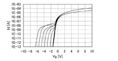
本実施例では、本発明の一態様に係るトランジスタについて説明する。具体的には、本実施例では、図1に示すトランジスタを作製し、当該トランジスタの特性を評価した結果について説明する。 In this example, a transistor according to one embodiment of the present invention will be described. Specifically, in this embodiment, a result of manufacturing the transistor illustrated in FIG. 1 and evaluating characteristics of the transistor will be described.
<作製工程>
まず、当該トランジスタの作製工程について説明する。
<Production process>
First, a manufacturing process of the transistor is described.
始めに、当該トランジスタの下地層を形成した。具体的には、ガラス基板上に厚さ100nmの窒素珪素(SiN)膜と、当該窒素珪素(SiN)膜上の厚さ150nmの酸化窒化珪素膜との積層膜をプラズマCVD法を用いて成膜した。 First, a base layer of the transistor was formed. Specifically, a stacked film of a nitrogen silicon (SiN) film having a thickness of 100 nm and a silicon oxynitride film having a thickness of 150 nm on the nitrogen silicon (SiN) film is formed using a plasma CVD method. Filmed.
次いで、フッ化水素(HF)を用いて当該下地層表面を洗浄した。 Next, the surface of the underlayer was washed with hydrogen fluoride (HF).
次いで、ゲートを形成した。具体的には、当該下地層上に厚さ100nmのタングステン(W)膜をスパッタリング法を用いて成膜した。そして、当該タングステン(W)膜をフォトリソグラフィ法を用いて加工することによりゲートを形成した。 Next, a gate was formed. Specifically, a tungsten (W) film with a thickness of 100 nm was formed over the base layer by a sputtering method. And the gate was formed by processing the said tungsten (W) film | membrane using the photolithographic method.
次いで、ゲート絶縁層を形成した。具体的には、当該下地層及び当該ゲート上に厚さ100nmの酸化窒化珪素(SiON)膜をマイクロ波CVD法を用いて成膜した。 Next, a gate insulating layer was formed. Specifically, a silicon oxynitride (SiON) film with a thickness of 100 nm was formed over the base layer and the gate by a microwave CVD method.
次いで、酸化物半導体層を形成した。具体的には、当該ゲート絶縁層上に厚さ35nmの少なくともインジウム(In)、ガリウム(Ga)、亜鉛(Zn)、及び酸素(O)を含む膜をスパッタリング法を用いて成膜した。そして、当該膜をフォトリソグラフィ法を用いて加工することにより酸化物半導体層を形成した。 Next, an oxide semiconductor layer was formed. Specifically, a film containing at least indium (In), gallium (Ga), zinc (Zn), and oxygen (O) with a thickness of 35 nm was formed over the gate insulating layer by a sputtering method. Then, the oxide semiconductor layer was formed by processing the film using a photolithography method.
次いで、窒素(N2)雰囲気下で350℃、1時間の熱処理、及び窒素(N2)及び酸素(O2)の混合雰囲気下で350℃、1時間の熱処理を行った。 Next, heat treatment was performed at 350 ° C. for 1 hour in a nitrogen (N 2 ) atmosphere, and heat treatment was performed at 350 ° C. for 1 hour in a mixed atmosphere of nitrogen (N 2 ) and oxygen (O 2 ).
次いで、ソース及びドレインを形成した。具体的には、当該ゲート絶縁層及び当該酸化物半導体層上に厚さ100nmのチタン(Ti)膜と、当該チタン(Ti)膜上の厚さ400nmのアルミニウム(Al)膜と、当該アルミニウム(Al)膜上の厚さ100nmのチタン(Ti)膜との積層膜をスパッタリング法を用いて成膜した。そして、当該積層膜をフォトリソグラフィ法を用いて加工することにより、ソース及びドレインを形成した。 Next, a source and a drain were formed. Specifically, a titanium (Ti) film with a thickness of 100 nm on the gate insulating layer and the oxide semiconductor layer, an aluminum (Al) film with a thickness of 400 nm on the titanium (Ti) film, and the aluminum ( A laminated film with a titanium (Ti) film having a thickness of 100 nm on an (Al) film was formed by sputtering. And the source and drain were formed by processing the said laminated film using the photolithographic method.
次いで、窒素(N2)及び酸素(O2)の混合雰囲気下で300℃、1時間の熱処理を行った。 Next, heat treatment was performed at 300 ° C. for 1 hour in a mixed atmosphere of nitrogen (N 2 ) and oxygen (O 2 ).
次いで、220℃、120秒の亜酸化窒素(N2O)プラズマ処理を行った。 Next, nitrous oxide (N 2 O) plasma treatment was performed at 220 ° C. for 120 seconds.
次いで、絶縁層を形成した。具体的には、当該ゲート絶縁層、当該酸化物半導体層、並びに当該ソース及び当該ドレイン上に厚さ600nmの酸化窒化珪素(SiON)膜をプラズマCVD法を用いて成膜した。 Next, an insulating layer was formed. Specifically, a 600-nm-thick silicon oxynitride (SiON) film was formed over the gate insulating layer, the oxide semiconductor layer, the source, and the drain by a plasma CVD method.
次いで、窒素(N2)及び酸素(O2)の混合雰囲気下で300℃、1時間の熱処理を行った。 Next, heat treatment was performed at 300 ° C. for 1 hour in a mixed atmosphere of nitrogen (N 2 ) and oxygen (O 2 ).
次いで、当該絶縁層上に厚さ1500nmのアクリルを形成した後、窒素(N2)雰囲気下で250℃、1時間の熱処理を行うことで当該アクリルを焼成した。 Next, after an acrylic film having a thickness of 1500 nm was formed on the insulating layer, the acrylic film was baked by performing heat treatment at 250 ° C. for 1 hour in a nitrogen (N 2 ) atmosphere.
次いで、透明導電層を形成した。具体的には、当該アクリル上に少なくともインジウム(In)、錫(Sn)、珪素(Si)、及び酸素(O)を含む膜をスパッタリング法を用いて成膜した。なお、当該膜が上述のドレインと接するように予め当該ドレイン上の絶縁層及びアクリルには開口部を設けた。 Next, a transparent conductive layer was formed. Specifically, a film containing at least indium (In), tin (Sn), silicon (Si), and oxygen (O) was formed over the acrylic film by a sputtering method. Note that an opening was provided in advance in the insulating layer and the acrylic over the drain so that the film was in contact with the drain.
最後に、窒素(N2)雰囲気下で250℃、1時間の熱処理を行った。 Finally, heat treatment was performed at 250 ° C. for 1 hour in a nitrogen (N 2 ) atmosphere.
<電気特性>
上述の工程によって得られたトランジスタに対して、光照射条件下におけるプラスゲートBT試験を行った。なお、本実施例において、プラスゲートBT試験とは、80℃においてゲートとソースの間の電圧が30Vの状態を特定の時間に渡って保持させる試験を指す。本実施例では、上述のトランジスタを複数用意し、それぞれのトランジスタに対して、2000秒以下の各種の時間に渡って当該試験を行った。
<Electrical characteristics>
A plus gate BT test under light irradiation conditions was performed on the transistor obtained by the above-described process. In the present embodiment, the plus gate BT test refers to a test in which the voltage between the gate and the source is maintained at 80 ° C. for a specific time. In this example, a plurality of the above-described transistors were prepared, and the test was performed on each transistor for various times of 2000 seconds or less.
図5は、当該試験後の本実施例に係る複数のトランジスタのそれぞれのVg−Id曲線を示す図である。図5より、本実施例に係るトランジスタは、当該試験後であってもスイッチング特性が大きくばらつかないことが分かった。 FIG. 5 is a diagram showing Vg-Id curves of a plurality of transistors according to this example after the test. FIG. 5 shows that the switching characteristics of the transistor according to this example do not vary greatly even after the test.
<比較例>
以下では、比較例として、ソース及びドレインが酸化物半導体層の端部と接するトランジスタについて説明する。
<Comparative example>
Hereinafter, as a comparative example, a transistor in which a source and a drain are in contact with an end portion of an oxide semiconductor layer will be described.
図6は、本比較例に係るトランジスタの構造を示す平面図である。図6に示すトランジスタは、ゲート1001と、ゲート1001上に設けられたゲート絶縁層と、ゲート絶縁層上の酸化物半導体層1003と、酸化物半導体層1003上のソース1004及びドレイン1006とを有する。図6に示すようにソース1004及びドレイン1006は、酸化物半導体層1003の端部に接している。
FIG. 6 is a plan view showing a structure of a transistor according to this comparative example. The transistor illustrated in FIG. 6 includes a
なお、本比較例に係るトランジスタは、上記実施例に係るトランジスタの各構成要素と同じ材料、作製工程を用いて形成した。そして、本比較例に係るトランジスタを複数用意し、それぞれのトランジスタに対して、2000秒以下の各種の時間に渡って光照射条件下におけるプラスゲートBT試験を行った。 Note that the transistor according to this comparative example was formed using the same materials and manufacturing steps as those of the components of the transistor according to the above example. Then, a plurality of transistors according to this comparative example were prepared, and a plus gate BT test under light irradiation conditions was performed on each transistor for various times of 2000 seconds or less.
図7は、当該試験後の本比較例に係る複数のトランジスタのそれぞれのVg−Id曲線を示す図である。図7より、本比較例に係るトランジスタは、当該試験後においてスイッチング特性が大きくばらつくことが分かった。 FIG. 7 is a diagram showing Vg-Id curves of a plurality of transistors according to this comparative example after the test. From FIG. 7, it was found that the switching characteristics of the transistor according to this comparative example greatly vary after the test.
10 基板
11 ゲート
12 ゲート絶縁層
13 酸化物半導体層
14 ソース
15 ドレイン
16 絶縁層
17 導電層
24 ソース
30 基板
31 ゲート
32 ゲート絶縁層
33 酸化物半導体層
34 ソース
35 絶縁層
36 ドレイン
100 画素部
110 走査線駆動回路
120 信号線駆動回路
130 走査線
140 信号線
150 画素
151 トランジスタ
152 容量素子
153 液晶素子
160 透明導電層
1001 ゲート
1003 酸化物半導体層
1004 ソース
1006 ドレイン
DESCRIPTION OF
Claims (2)
前記ゲート電極上のゲート絶縁層と、
前記ゲート絶縁層上の酸化物半導体層と、
前記酸化物半導体層上のソース電極及びドレイン電極と、を有し、
前記酸化物半導体層全体は、前記ゲート電極と重なり、
前記ソース電極及び前記ドレイン電極の一方の内側に、前記ソース電極及び前記ドレイン電極の他方が配置され、
前記ソース電極及び前記ドレイン電極の一方は、間隙を有し、
前記ソース電極及び前記ドレイン電極の他方に電気的に接続される導電層は、前記間隙と重なり、且つ、前記ソース電極及び前記ドレイン電極の一方と重ならないように配置され、
前記ソース電極及び前記ドレイン電極の他方は前記酸化物半導体層の側面と接しないことを特徴とする半導体装置。 A gate electrode;
A gate insulating layer on the gate electrode;
An oxide semiconductor layer over the gate insulating layer;
A source electrode and a drain electrode on the oxide semiconductor layer,
The entire oxide semiconductor layer overlaps with the gate electrode,
The other of the source electrode and the drain electrode is disposed inside one of the source electrode and the drain electrode,
One of the source electrode and the drain electrode has a gap,
A conductive layer electrically connected to the other of the source electrode and the drain electrode is disposed so as to overlap with the gap and not overlap with one of the source electrode and the drain electrode ;
The other of the source electrode and the drain electrode is not in contact with a side surface of the oxide semiconductor layer .
前記ゲート電極上のゲート絶縁層と、A gate insulating layer on the gate electrode;
前記ゲート絶縁層上の酸化物半導体層と、An oxide semiconductor layer over the gate insulating layer;
前記酸化物半導体層上のソース電極及びドレイン電極と、を有し、A source electrode and a drain electrode on the oxide semiconductor layer,
前記酸化物半導体層全体は、前記ゲート電極と重なり、The entire oxide semiconductor layer overlaps with the gate electrode,
前記ソース電極及び前記ドレイン電極の一方の内側に、前記ソース電極及び前記ドレイン電極の他方が配置され、The other of the source electrode and the drain electrode is disposed inside one of the source electrode and the drain electrode,
前記ソース電極及び前記ドレイン電極の一方は、間隙を有し、One of the source electrode and the drain electrode has a gap,
前記ソース電極及び前記ドレイン電極の他方に電気的に接続される導電層は、前記間隙と重なり、且つ、前記ソース電極及び前記ドレイン電極の一方と重ならないように配置され、A conductive layer electrically connected to the other of the source electrode and the drain electrode is disposed so as to overlap with the gap and not overlap with one of the source electrode and the drain electrode;
前記ソース電極及び前記ドレイン電極の他方は前記酸化物半導体層の上面のみと接することを特徴とする半導体装置。The other of the source electrode and the drain electrode is in contact with only the upper surface of the oxide semiconductor layer.
Priority Applications (1)
| Application Number | Priority Date | Filing Date | Title |
|---|---|---|---|
| JP2012255559A JP6147992B2 (en) | 2011-11-30 | 2012-11-21 | Semiconductor device |
Applications Claiming Priority (3)
| Application Number | Priority Date | Filing Date | Title |
|---|---|---|---|
| JP2011262234 | 2011-11-30 | ||
| JP2011262234 | 2011-11-30 | ||
| JP2012255559A JP6147992B2 (en) | 2011-11-30 | 2012-11-21 | Semiconductor device |
Related Child Applications (1)
| Application Number | Title | Priority Date | Filing Date |
|---|---|---|---|
| JP2017099049A Division JP6363258B2 (en) | 2011-11-30 | 2017-05-18 | Semiconductor device |
Publications (3)
| Publication Number | Publication Date |
|---|---|
| JP2013138185A JP2013138185A (en) | 2013-07-11 |
| JP2013138185A5 JP2013138185A5 (en) | 2015-12-03 |
| JP6147992B2 true JP6147992B2 (en) | 2017-06-14 |
Family
ID=48465998
Family Applications (2)
| Application Number | Title | Priority Date | Filing Date |
|---|---|---|---|
| JP2012255559A Expired - Fee Related JP6147992B2 (en) | 2011-11-30 | 2012-11-21 | Semiconductor device |
| JP2017099049A Active JP6363258B2 (en) | 2011-11-30 | 2017-05-18 | Semiconductor device |
Family Applications After (1)
| Application Number | Title | Priority Date | Filing Date |
|---|---|---|---|
| JP2017099049A Active JP6363258B2 (en) | 2011-11-30 | 2017-05-18 | Semiconductor device |
Country Status (5)
| Country | Link |
|---|---|
| US (2) | US8872179B2 (en) |
| JP (2) | JP6147992B2 (en) |
| KR (2) | KR20130061069A (en) |
| CN (1) | CN103137701B (en) |
| TW (1) | TWI608623B (en) |
Families Citing this family (16)
| Publication number | Priority date | Publication date | Assignee | Title |
|---|---|---|---|---|
| JP6053490B2 (en) | 2011-12-23 | 2016-12-27 | 株式会社半導体エネルギー研究所 | Method for manufacturing semiconductor device |
| KR102101167B1 (en) | 2012-02-03 | 2020-04-16 | 가부시키가이샤 한도오따이 에네루기 켄큐쇼 | Semiconductor device |
| US9362417B2 (en) | 2012-02-03 | 2016-06-07 | Semiconductor Energy Laboratory Co., Ltd. | Semiconductor device |
| US9112037B2 (en) | 2012-02-09 | 2015-08-18 | Semiconductor Energy Laboratory Co., Ltd. | Semiconductor device |
| US9461066B2 (en) * | 2012-08-10 | 2016-10-04 | Boe Technology Group Co., Ltd. | Thin film transistor and method of manufacturing the same, array substrate and display device |
| US10529740B2 (en) * | 2013-07-25 | 2020-01-07 | Semiconductor Energy Laboratory Co., Ltd. | Semiconductor device including semiconductor layer and conductive layer |
| US9722090B2 (en) | 2014-06-23 | 2017-08-01 | Semiconductor Energy Laboratory Co., Ltd. | Semiconductor device including first gate oxide semiconductor film, and second gate |
| US9633710B2 (en) | 2015-01-23 | 2017-04-25 | Semiconductor Energy Laboratory Co., Ltd. | Method for operating semiconductor device |
| US10978489B2 (en) * | 2015-07-24 | 2021-04-13 | Semiconductor Energy Laboratory Co., Ltd. | Semiconductor device, display panel, method for manufacturing semiconductor device, method for manufacturing display panel, and information processing device |
| KR102390441B1 (en) * | 2015-10-15 | 2022-04-26 | 삼성디스플레이 주식회사 | Organic light emitting display device |
| JP6827328B2 (en) * | 2016-01-15 | 2021-02-10 | 株式会社半導体エネルギー研究所 | Semiconductor devices and electronic devices |
| JP7293190B2 (en) | 2018-03-16 | 2023-06-19 | 株式会社半導体エネルギー研究所 | semiconductor equipment |
| JP7055535B2 (en) * | 2018-09-20 | 2022-04-18 | 株式会社東芝 | Semiconductor device |
| CN110797395A (en) * | 2019-09-18 | 2020-02-14 | 华南理工大学 | Doped metal oxide semiconductor, thin film transistor and application |
| US11379231B2 (en) | 2019-10-25 | 2022-07-05 | Semiconductor Energy Laboratory Co., Ltd. | Data processing system and operation method of data processing system |
| CN111081160B (en) * | 2019-12-31 | 2022-01-04 | 上海天马微电子有限公司 | Display panel, display device and manufacturing method of display panel |
Family Cites Families (122)
| Publication number | Priority date | Publication date | Assignee | Title |
|---|---|---|---|---|
| JPS60198861A (en) | 1984-03-23 | 1985-10-08 | Fujitsu Ltd | Thin film transistor |
| JPH0244256B2 (en) | 1987-01-28 | 1990-10-03 | Kagaku Gijutsucho Mukizaishitsu Kenkyushocho | INGAZN2O5DESHIMESARERUROTSUHOSHOKEINOSOJOKOZOOJUSURUKAGOBUTSUOYOBISONOSEIZOHO |
| JPH0244258B2 (en) | 1987-02-24 | 1990-10-03 | Kagaku Gijutsucho Mukizaishitsu Kenkyushocho | INGAZN3O6DESHIMESARERUROTSUHOSHOKEINOSOJOKOZOOJUSURUKAGOBUTSUOYOBISONOSEIZOHO |
| JPH0244260B2 (en) | 1987-02-24 | 1990-10-03 | Kagaku Gijutsucho Mukizaishitsu Kenkyushocho | INGAZN5O8DESHIMESARERUROTSUHOSHOKEINOSOJOKOZOOJUSURUKAGOBUTSUOYOBISONOSEIZOHO |
| JPS63210023A (en) | 1987-02-24 | 1988-08-31 | Natl Inst For Res In Inorg Mater | Compound having laminar structure of hexagonal crystal system expressed by ingazn4o7 and its production |
| JPH0244262B2 (en) | 1987-02-27 | 1990-10-03 | Kagaku Gijutsucho Mukizaishitsu Kenkyushocho | INGAZN6O9DESHIMESARERUROTSUHOSHOKEINOSOJOKOZOOJUSURUKAGOBUTSUOYOBISONOSEIZOHO |
| JPH0244263B2 (en) | 1987-04-22 | 1990-10-03 | Kagaku Gijutsucho Mukizaishitsu Kenkyushocho | INGAZN7O10DESHIMESARERUROTSUHOSHOKEINOSOJOKOZOOJUSURUKAGOBUTSUOYOBISONOSEIZOHO |
| JPH05251705A (en) | 1992-03-04 | 1993-09-28 | Fuji Xerox Co Ltd | Thin-film transistor |
| JPH08160469A (en) * | 1994-08-31 | 1996-06-21 | Semiconductor Energy Lab Co Ltd | Liquid crystal display device |
| JP3479375B2 (en) | 1995-03-27 | 2003-12-15 | 科学技術振興事業団 | Metal oxide semiconductor device in which a pn junction is formed with a thin film transistor made of a metal oxide semiconductor such as cuprous oxide, and methods for manufacturing the same |
| EP0820644B1 (en) | 1995-08-03 | 2005-08-24 | Koninklijke Philips Electronics N.V. | Semiconductor device provided with transparent switching element |
| JP3625598B2 (en) | 1995-12-30 | 2005-03-02 | 三星電子株式会社 | Manufacturing method of liquid crystal display device |
| JP4170454B2 (en) | 1998-07-24 | 2008-10-22 | Hoya株式会社 | Article having transparent conductive oxide thin film and method for producing the same |
| JP2000150861A (en) | 1998-11-16 | 2000-05-30 | Tdk Corp | Oxide thin film |
| JP3276930B2 (en) | 1998-11-17 | 2002-04-22 | 科学技術振興事業団 | Transistor and semiconductor device |
| TW460731B (en) | 1999-09-03 | 2001-10-21 | Ind Tech Res Inst | Electrode structure and production method of wide viewing angle LCD |
| JP4089858B2 (en) | 2000-09-01 | 2008-05-28 | 国立大学法人東北大学 | Semiconductor device |
| KR20020038482A (en) | 2000-11-15 | 2002-05-23 | 모리시타 요이찌 | Thin film transistor array, method for producing the same, and display panel using the same |
| JP3997731B2 (en) | 2001-03-19 | 2007-10-24 | 富士ゼロックス株式会社 | Method for forming a crystalline semiconductor thin film on a substrate |
| JP2002289859A (en) | 2001-03-23 | 2002-10-04 | Minolta Co Ltd | Thin-film transistor |
| JP3925839B2 (en) | 2001-09-10 | 2007-06-06 | シャープ株式会社 | Semiconductor memory device and test method thereof |
| JP4090716B2 (en) | 2001-09-10 | 2008-05-28 | 雅司 川崎 | Thin film transistor and matrix display device |
| WO2003040441A1 (en) | 2001-11-05 | 2003-05-15 | Japan Science And Technology Agency | Natural superlattice homologous single crystal thin film, method for preparation thereof, and device using said single crystal thin film |
| JP4164562B2 (en) | 2002-09-11 | 2008-10-15 | 独立行政法人科学技術振興機構 | Transparent thin film field effect transistor using homologous thin film as active layer |
| JP4083486B2 (en) | 2002-02-21 | 2008-04-30 | 独立行政法人科学技術振興機構 | Method for producing LnCuO (S, Se, Te) single crystal thin film |
| CN1445821A (en) | 2002-03-15 | 2003-10-01 | 三洋电机株式会社 | Forming method of ZnO film and ZnO semiconductor layer, semiconductor element and manufacturing method thereof |
| JP3933591B2 (en) | 2002-03-26 | 2007-06-20 | 淳二 城戸 | Organic electroluminescent device |
| US7339187B2 (en) | 2002-05-21 | 2008-03-04 | State Of Oregon Acting By And Through The Oregon State Board Of Higher Education On Behalf Of Oregon State University | Transistor structures |
| JP2004022625A (en) | 2002-06-13 | 2004-01-22 | Murata Mfg Co Ltd | Manufacturing method of semiconductor device and its manufacturing method |
| US7105868B2 (en) | 2002-06-24 | 2006-09-12 | Cermet, Inc. | High-electron mobility transistor with zinc oxide |
| US7067843B2 (en) | 2002-10-11 | 2006-06-27 | E. I. Du Pont De Nemours And Company | Transparent oxide semiconductor thin film transistors |
| JP4166105B2 (en) | 2003-03-06 | 2008-10-15 | シャープ株式会社 | Semiconductor device and manufacturing method thereof |
| JP2004273732A (en) | 2003-03-07 | 2004-09-30 | Sharp Corp | Active matrix substrate and its producing process |
| JP4108633B2 (en) | 2003-06-20 | 2008-06-25 | シャープ株式会社 | THIN FILM TRANSISTOR, MANUFACTURING METHOD THEREOF, AND ELECTRONIC DEVICE |
| US7262463B2 (en) | 2003-07-25 | 2007-08-28 | Hewlett-Packard Development Company, L.P. | Transistor including a deposited channel region having a doped portion |
| JP2005084416A (en) * | 2003-09-09 | 2005-03-31 | Sharp Corp | Active matrix substrate and display device using it |
| CN1998087B (en) | 2004-03-12 | 2014-12-31 | 独立行政法人科学技术振兴机构 | Amorphous oxide and thin film transistor |
| US7282782B2 (en) | 2004-03-12 | 2007-10-16 | Hewlett-Packard Development Company, L.P. | Combined binary oxide semiconductor device |
| US7297977B2 (en) | 2004-03-12 | 2007-11-20 | Hewlett-Packard Development Company, L.P. | Semiconductor device |
| US7145174B2 (en) | 2004-03-12 | 2006-12-05 | Hewlett-Packard Development Company, Lp. | Semiconductor device |
| US7211825B2 (en) | 2004-06-14 | 2007-05-01 | Yi-Chi Shih | Indium oxide-based thin film transistors and circuits |
| JP2006100760A (en) | 2004-09-02 | 2006-04-13 | Casio Comput Co Ltd | Thin-film transistor and its manufacturing method |
| US7285501B2 (en) | 2004-09-17 | 2007-10-23 | Hewlett-Packard Development Company, L.P. | Method of forming a solution processed device |
| JP2006093597A (en) * | 2004-09-27 | 2006-04-06 | Shin Etsu Handotai Co Ltd | Method of evaluating semiconductor wafer |
| US7298084B2 (en) | 2004-11-02 | 2007-11-20 | 3M Innovative Properties Company | Methods and displays utilizing integrated zinc oxide row and column drivers in conjunction with organic light emitting diodes |
| RU2399989C2 (en) | 2004-11-10 | 2010-09-20 | Кэнон Кабусики Кайся | Amorphous oxide and field-effect transistor using said oxide |
| US7829444B2 (en) | 2004-11-10 | 2010-11-09 | Canon Kabushiki Kaisha | Field effect transistor manufacturing method |
| US7868326B2 (en) | 2004-11-10 | 2011-01-11 | Canon Kabushiki Kaisha | Field effect transistor |
| WO2006051994A2 (en) | 2004-11-10 | 2006-05-18 | Canon Kabushiki Kaisha | Light-emitting device |
| US7453065B2 (en) | 2004-11-10 | 2008-11-18 | Canon Kabushiki Kaisha | Sensor and image pickup device |
| US7791072B2 (en) | 2004-11-10 | 2010-09-07 | Canon Kabushiki Kaisha | Display |
| US7863611B2 (en) | 2004-11-10 | 2011-01-04 | Canon Kabushiki Kaisha | Integrated circuits utilizing amorphous oxides |
| US7579224B2 (en) | 2005-01-21 | 2009-08-25 | Semiconductor Energy Laboratory Co., Ltd. | Method for manufacturing a thin film semiconductor device |
| TWI569441B (en) | 2005-01-28 | 2017-02-01 | 半導體能源研究所股份有限公司 | Semiconductor device, electronic device, and method of manufacturing semiconductor device |
| TWI412138B (en) | 2005-01-28 | 2013-10-11 | Semiconductor Energy Lab | Semiconductor device, electronic device, and method of manufacturing semiconductor device |
| US7858451B2 (en) | 2005-02-03 | 2010-12-28 | Semiconductor Energy Laboratory Co., Ltd. | Electronic device, semiconductor device and manufacturing method thereof |
| US7948171B2 (en) | 2005-02-18 | 2011-05-24 | Semiconductor Energy Laboratory Co., Ltd. | Light emitting device |
| US20060197092A1 (en) | 2005-03-03 | 2006-09-07 | Randy Hoffman | System and method for forming conductive material on a substrate |
| US8681077B2 (en) | 2005-03-18 | 2014-03-25 | Semiconductor Energy Laboratory Co., Ltd. | Semiconductor device, and display device, driving method and electronic apparatus thereof |
| WO2006105077A2 (en) | 2005-03-28 | 2006-10-05 | Massachusetts Institute Of Technology | Low voltage thin film transistor with high-k dielectric material |
| JP4887647B2 (en) * | 2005-03-31 | 2012-02-29 | 凸版印刷株式会社 | Method for manufacturing thin film transistor device |
| JP4887646B2 (en) * | 2005-03-31 | 2012-02-29 | 凸版印刷株式会社 | THIN FILM TRANSISTOR DEVICE AND ITS MANUFACTURING METHOD, THIN FILM TRANSISTOR ARRAY AND THIN FILM TRANSISTOR DISPLAY |
| US7645478B2 (en) | 2005-03-31 | 2010-01-12 | 3M Innovative Properties Company | Methods of making displays |
| US8300031B2 (en) | 2005-04-20 | 2012-10-30 | Semiconductor Energy Laboratory Co., Ltd. | Semiconductor device comprising transistor having gate and drain connected through a current-voltage conversion element |
| JP5243686B2 (en) | 2005-04-28 | 2013-07-24 | エルジー ディスプレイ カンパニー リミテッド | Thin film transistor |
| JP5116251B2 (en) * | 2005-05-20 | 2013-01-09 | 株式会社半導体エネルギー研究所 | Method for manufacturing semiconductor device |
| US7537976B2 (en) * | 2005-05-20 | 2009-05-26 | Semiconductor Energy Laboratory Co., Ltd. | Manufacturing method of thin film transistor |
| JP2006344849A (en) | 2005-06-10 | 2006-12-21 | Casio Comput Co Ltd | Thin film transistor |
| US7691666B2 (en) | 2005-06-16 | 2010-04-06 | Eastman Kodak Company | Methods of making thin film transistors comprising zinc-oxide-based semiconductor materials and transistors made thereby |
| US7402506B2 (en) | 2005-06-16 | 2008-07-22 | Eastman Kodak Company | Methods of making thin film transistors comprising zinc-oxide-based semiconductor materials and transistors made thereby |
| US7507618B2 (en) | 2005-06-27 | 2009-03-24 | 3M Innovative Properties Company | Method for making electronic devices using metal oxide nanoparticles |
| KR100711890B1 (en) | 2005-07-28 | 2007-04-25 | 삼성에스디아이 주식회사 | Organic Light Emitting Display and Fabrication Method for the same |
| JP2007059128A (en) | 2005-08-23 | 2007-03-08 | Canon Inc | Organic electroluminescent display device and manufacturing method thereof |
| JP4850457B2 (en) | 2005-09-06 | 2012-01-11 | キヤノン株式会社 | Thin film transistor and thin film diode |
| JP4280736B2 (en) | 2005-09-06 | 2009-06-17 | キヤノン株式会社 | Semiconductor element |
| JP5116225B2 (en) | 2005-09-06 | 2013-01-09 | キヤノン株式会社 | Manufacturing method of oxide semiconductor device |
| JP2007073705A (en) | 2005-09-06 | 2007-03-22 | Canon Inc | Oxide-semiconductor channel film transistor and its method of manufacturing same |
| EP1995787A3 (en) | 2005-09-29 | 2012-01-18 | Semiconductor Energy Laboratory Co, Ltd. | Semiconductor device having oxide semiconductor layer and manufacturing method therof |
| JP5064747B2 (en) * | 2005-09-29 | 2012-10-31 | 株式会社半導体エネルギー研究所 | Semiconductor device, electrophoretic display device, display module, electronic device, and method for manufacturing semiconductor device |
| JP5078246B2 (en) * | 2005-09-29 | 2012-11-21 | 株式会社半導体エネルギー研究所 | Semiconductor device and manufacturing method of semiconductor device |
| JP5037808B2 (en) | 2005-10-20 | 2012-10-03 | キヤノン株式会社 | Field effect transistor using amorphous oxide, and display device using the transistor |
| CN101577282A (en) | 2005-11-15 | 2009-11-11 | 株式会社半导体能源研究所 | Semiconductor device and method of manufacturing the same |
| TWI292281B (en) | 2005-12-29 | 2008-01-01 | Ind Tech Res Inst | Pixel structure of active organic light emitting diode and method of fabricating the same |
| US7867636B2 (en) | 2006-01-11 | 2011-01-11 | Murata Manufacturing Co., Ltd. | Transparent conductive film and method for manufacturing the same |
| JP4977478B2 (en) | 2006-01-21 | 2012-07-18 | 三星電子株式会社 | ZnO film and method of manufacturing TFT using the same |
| KR101189279B1 (en) | 2006-01-26 | 2012-10-09 | 삼성디스플레이 주식회사 | Display device and manufacturing method of the same |
| US7576394B2 (en) | 2006-02-02 | 2009-08-18 | Kochi Industrial Promotion Center | Thin film transistor including low resistance conductive thin films and manufacturing method thereof |
| US7977169B2 (en) | 2006-02-15 | 2011-07-12 | Kochi Industrial Promotion Center | Semiconductor device including active layer made of zinc oxide with controlled orientations and manufacturing method thereof |
| KR20070101595A (en) | 2006-04-11 | 2007-10-17 | 삼성전자주식회사 | Zno thin film transistor |
| US20070252928A1 (en) | 2006-04-28 | 2007-11-01 | Toppan Printing Co., Ltd. | Structure, transmission type liquid crystal display, reflection type display and manufacturing method thereof |
| JP5028033B2 (en) | 2006-06-13 | 2012-09-19 | キヤノン株式会社 | Oxide semiconductor film dry etching method |
| JP4999400B2 (en) | 2006-08-09 | 2012-08-15 | キヤノン株式会社 | Oxide semiconductor film dry etching method |
| JP4609797B2 (en) | 2006-08-09 | 2011-01-12 | Nec液晶テクノロジー株式会社 | Thin film device and manufacturing method thereof |
| JP4332545B2 (en) | 2006-09-15 | 2009-09-16 | キヤノン株式会社 | Field effect transistor and manufacturing method thereof |
| JP5164357B2 (en) | 2006-09-27 | 2013-03-21 | キヤノン株式会社 | Semiconductor device and manufacturing method of semiconductor device |
| JP4274219B2 (en) | 2006-09-27 | 2009-06-03 | セイコーエプソン株式会社 | Electronic devices, organic electroluminescence devices, organic thin film semiconductor devices |
| US7622371B2 (en) | 2006-10-10 | 2009-11-24 | Hewlett-Packard Development Company, L.P. | Fused nanocrystal thin film semiconductor and method |
| US7772021B2 (en) | 2006-11-29 | 2010-08-10 | Samsung Electronics Co., Ltd. | Flat panel displays comprising a thin-film transistor having a semiconductive oxide in its channel and methods of fabricating the same for use in flat panel displays |
| JP2008140684A (en) | 2006-12-04 | 2008-06-19 | Toppan Printing Co Ltd | Color el display, and its manufacturing method |
| KR101303578B1 (en) | 2007-01-05 | 2013-09-09 | 삼성전자주식회사 | Etching method of thin film |
| US8207063B2 (en) | 2007-01-26 | 2012-06-26 | Eastman Kodak Company | Process for atomic layer deposition |
| KR100851215B1 (en) | 2007-03-14 | 2008-08-07 | 삼성에스디아이 주식회사 | Thin film transistor and organic light-emitting dislplay device having the thin film transistor |
| US7795613B2 (en) | 2007-04-17 | 2010-09-14 | Toppan Printing Co., Ltd. | Structure with transistor |
| KR101325053B1 (en) * | 2007-04-18 | 2013-11-05 | 삼성디스플레이 주식회사 | Thin film transistor substrate and manufacturing method thereof |
| KR20080094300A (en) | 2007-04-19 | 2008-10-23 | 삼성전자주식회사 | Thin film transistor and method of manufacturing the same and flat panel display comprising the same |
| KR101334181B1 (en) | 2007-04-20 | 2013-11-28 | 삼성전자주식회사 | Thin Film Transistor having selectively crystallized channel layer and method of manufacturing the same |
| WO2008133345A1 (en) | 2007-04-25 | 2008-11-06 | Canon Kabushiki Kaisha | Oxynitride semiconductor |
| KR101345376B1 (en) | 2007-05-29 | 2013-12-24 | 삼성전자주식회사 | Fabrication method of ZnO family Thin film transistor |
| KR101381251B1 (en) * | 2007-06-14 | 2014-04-04 | 삼성디스플레이 주식회사 | Thin film transistor and display panel having the same |
| US8202365B2 (en) | 2007-12-17 | 2012-06-19 | Fujifilm Corporation | Process for producing oriented inorganic crystalline film, and semiconductor device using the oriented inorganic crystalline film |
| JP5436017B2 (en) * | 2008-04-25 | 2014-03-05 | 株式会社半導体エネルギー研究所 | Semiconductor device |
| JP5704790B2 (en) * | 2008-05-07 | 2015-04-22 | キヤノン株式会社 | Thin film transistor and display device |
| KR100963027B1 (en) * | 2008-06-30 | 2010-06-10 | 삼성모바일디스플레이주식회사 | Thin film transistor, method of manufacturing the thin film transistor and flat panel display device having the thin film transistor |
| JP4623179B2 (en) | 2008-09-18 | 2011-02-02 | ソニー株式会社 | Thin film transistor and manufacturing method thereof |
| JP5451280B2 (en) | 2008-10-09 | 2014-03-26 | キヤノン株式会社 | Wurtzite crystal growth substrate, manufacturing method thereof, and semiconductor device |
| KR101612147B1 (en) * | 2008-10-23 | 2016-04-12 | 이데미쓰 고산 가부시키가이샤 | Thin film transistor and method for manufacturing same |
| JP2010123595A (en) * | 2008-11-17 | 2010-06-03 | Sony Corp | Thin film transistor and display |
| US8704216B2 (en) * | 2009-02-27 | 2014-04-22 | Semiconductor Energy Laboratory Co., Ltd. | Semiconductor device and manufacturing method thereof |
| JP2010272568A (en) * | 2009-05-19 | 2010-12-02 | Hitachi Displays Ltd | Display and method of manufacturing the same |
| TWI512997B (en) | 2009-09-24 | 2015-12-11 | Semiconductor Energy Lab | Semiconductor device, power circuit, and manufacturing method of semiconductor device |
| JP2012015436A (en) * | 2010-07-05 | 2012-01-19 | Sony Corp | Thin film transistor and display device |
| TW201314782A (en) * | 2011-09-23 | 2013-04-01 | Hon Hai Prec Ind Co Ltd | A method for making thin film transistor |
-
2012
- 2012-11-21 JP JP2012255559A patent/JP6147992B2/en not_active Expired - Fee Related
- 2012-11-21 CN CN201210475836.8A patent/CN103137701B/en not_active Expired - Fee Related
- 2012-11-22 TW TW101143749A patent/TWI608623B/en not_active IP Right Cessation
- 2012-11-26 KR KR1020120134339A patent/KR20130061069A/en not_active Application Discontinuation
- 2012-11-28 US US13/687,461 patent/US8872179B2/en active Active
-
2014
- 2014-10-23 US US14/521,540 patent/US9093543B2/en active Active
-
2017
- 2017-05-18 JP JP2017099049A patent/JP6363258B2/en active Active
-
2019
- 2019-09-20 KR KR1020190116086A patent/KR20190110977A/en not_active Application Discontinuation
Also Published As
| Publication number | Publication date |
|---|---|
| TWI608623B (en) | 2017-12-11 |
| US8872179B2 (en) | 2014-10-28 |
| JP6363258B2 (en) | 2018-07-25 |
| CN103137701A (en) | 2013-06-05 |
| CN103137701B (en) | 2018-01-19 |
| US9093543B2 (en) | 2015-07-28 |
| JP2017175154A (en) | 2017-09-28 |
| US20130134422A1 (en) | 2013-05-30 |
| KR20190110977A (en) | 2019-10-01 |
| KR20130061069A (en) | 2013-06-10 |
| JP2013138185A (en) | 2013-07-11 |
| US20150041819A1 (en) | 2015-02-12 |
| TW201327840A (en) | 2013-07-01 |
Similar Documents
| Publication | Publication Date | Title |
|---|---|---|
| JP6363258B2 (en) | Semiconductor device | |
| JP5608520B2 (en) | Method for manufacturing transistor | |
| JP6148311B2 (en) | Electronic equipment | |
| TWI497611B (en) | Semiconductor device and method for manufacturing the same | |
| US8932903B2 (en) | Method for forming wiring, semiconductor device, and method for manufacturing semiconductor device | |
| JP6004308B2 (en) | Thin film device | |
| JP5848089B2 (en) | Semiconductor device | |
| TW201207910A (en) | Non-linear element, display device including non-linear element, and electronic device including display device | |
| WO2014034872A1 (en) | Thin film transistor and display device | |
| WO2014034874A1 (en) | Thin film transistor and display device | |
| KR101861887B1 (en) | Method for driving semiconductor device | |
| JP6260992B2 (en) | Thin film transistor and manufacturing method thereof | |
| JP2015103677A (en) | Thin-film transistor and method of manufacturing the same | |
| JP2014175360A (en) | Semiconductor device manufacturing method | |
| JP6179912B2 (en) | Thin film device and manufacturing method thereof |
Legal Events
| Date | Code | Title | Description |
|---|---|---|---|
| A521 | Written amendment |
Free format text: JAPANESE INTERMEDIATE CODE: A523 Effective date: 20151019 |
|
| A621 | Written request for application examination |
Free format text: JAPANESE INTERMEDIATE CODE: A621 Effective date: 20151019 |
|
| A977 | Report on retrieval |
Free format text: JAPANESE INTERMEDIATE CODE: A971007 Effective date: 20161012 |
|
| A131 | Notification of reasons for refusal |
Free format text: JAPANESE INTERMEDIATE CODE: A131 Effective date: 20161018 |
|
| A521 | Written amendment |
Free format text: JAPANESE INTERMEDIATE CODE: A523 Effective date: 20161213 |
|
| TRDD | Decision of grant or rejection written | ||
| A01 | Written decision to grant a patent or to grant a registration (utility model) |
Free format text: JAPANESE INTERMEDIATE CODE: A01 Effective date: 20170418 |
|
| A61 | First payment of annual fees (during grant procedure) |
Free format text: JAPANESE INTERMEDIATE CODE: A61 Effective date: 20170518 |
|
| R150 | Certificate of patent or registration of utility model |
Ref document number: 6147992 Country of ref document: JP Free format text: JAPANESE INTERMEDIATE CODE: R150 |
|
| R250 | Receipt of annual fees |
Free format text: JAPANESE INTERMEDIATE CODE: R250 |
|
| LAPS | Cancellation because of no payment of annual fees |