JP5059110B2 - 柔軟性機械的サポートを構成するワイヤ要素用ハウジングを形成する凹部を具備するベアマイクロエレクトロニクスチップ、製造プロセスおよび微細構造 - Google Patents
柔軟性機械的サポートを構成するワイヤ要素用ハウジングを形成する凹部を具備するベアマイクロエレクトロニクスチップ、製造プロセスおよび微細構造 Download PDFInfo
- Publication number
- JP5059110B2 JP5059110B2 JP2009526145A JP2009526145A JP5059110B2 JP 5059110 B2 JP5059110 B2 JP 5059110B2 JP 2009526145 A JP2009526145 A JP 2009526145A JP 2009526145 A JP2009526145 A JP 2009526145A JP 5059110 B2 JP5059110 B2 JP 5059110B2
- Authority
- JP
- Japan
- Prior art keywords
- chip
- groove
- wire element
- recess
- microelectronic
- Prior art date
- Legal status (The legal status is an assumption and is not a legal conclusion. Google has not performed a legal analysis and makes no representation as to the accuracy of the status listed.)
- Active
Links
- 238000004377 microelectronic Methods 0.000 title claims abstract description 69
- 238000004519 manufacturing process Methods 0.000 title claims description 20
- 235000012431 wafers Nutrition 0.000 claims description 16
- 238000000034 method Methods 0.000 claims description 12
- 230000001154 acute effect Effects 0.000 claims description 2
- 210000000078 claw Anatomy 0.000 claims 1
- 239000010410 layer Substances 0.000 description 21
- 239000004020 conductor Substances 0.000 description 20
- 239000004744 fabric Substances 0.000 description 16
- 239000011810 insulating material Substances 0.000 description 13
- 239000004753 textile Substances 0.000 description 13
- 239000000758 substrate Substances 0.000 description 9
- 229910052751 metal Inorganic materials 0.000 description 8
- 239000002184 metal Substances 0.000 description 8
- 239000000853 adhesive Substances 0.000 description 7
- 230000001070 adhesive effect Effects 0.000 description 7
- PXHVJJICTQNCMI-UHFFFAOYSA-N Nickel Chemical compound [Ni] PXHVJJICTQNCMI-UHFFFAOYSA-N 0.000 description 6
- 238000004891 communication Methods 0.000 description 6
- 238000000151 deposition Methods 0.000 description 6
- 230000010354 integration Effects 0.000 description 5
- 239000011159 matrix material Substances 0.000 description 5
- 230000008021 deposition Effects 0.000 description 4
- 238000005868 electrolysis reaction Methods 0.000 description 4
- 238000003780 insertion Methods 0.000 description 4
- 230000037431 insertion Effects 0.000 description 4
- RYGMFSIKBFXOCR-UHFFFAOYSA-N Copper Chemical compound [Cu] RYGMFSIKBFXOCR-UHFFFAOYSA-N 0.000 description 3
- RTAQQCXQSZGOHL-UHFFFAOYSA-N Titanium Chemical compound [Ti] RTAQQCXQSZGOHL-UHFFFAOYSA-N 0.000 description 3
- 238000003486 chemical etching Methods 0.000 description 3
- 239000011248 coating agent Substances 0.000 description 3
- 238000000576 coating method Methods 0.000 description 3
- 229910052802 copper Inorganic materials 0.000 description 3
- 239000010949 copper Substances 0.000 description 3
- 239000000463 material Substances 0.000 description 3
- 229910052759 nickel Inorganic materials 0.000 description 3
- 238000001020 plasma etching Methods 0.000 description 3
- 229920005989 resin Polymers 0.000 description 3
- 239000011347 resin Substances 0.000 description 3
- 239000010936 titanium Substances 0.000 description 3
- 229910052719 titanium Inorganic materials 0.000 description 3
- 238000009941 weaving Methods 0.000 description 3
- 238000001039 wet etching Methods 0.000 description 3
- 229910052581 Si3N4 Inorganic materials 0.000 description 2
- VYPSYNLAJGMNEJ-UHFFFAOYSA-N Silicium dioxide Chemical compound O=[Si]=O VYPSYNLAJGMNEJ-UHFFFAOYSA-N 0.000 description 2
- 239000012790 adhesive layer Substances 0.000 description 2
- 238000005520 cutting process Methods 0.000 description 2
- 238000001312 dry etching Methods 0.000 description 2
- 239000002360 explosive Substances 0.000 description 2
- 239000000835 fiber Substances 0.000 description 2
- 238000009413 insulation Methods 0.000 description 2
- 238000003698 laser cutting Methods 0.000 description 2
- 238000000623 plasma-assisted chemical vapour deposition Methods 0.000 description 2
- 238000012545 processing Methods 0.000 description 2
- 230000008929 regeneration Effects 0.000 description 2
- 238000011069 regeneration method Methods 0.000 description 2
- 230000003014 reinforcing effect Effects 0.000 description 2
- 229910052710 silicon Inorganic materials 0.000 description 2
- 239000010703 silicon Substances 0.000 description 2
- HQVNEWCFYHHQES-UHFFFAOYSA-N silicon nitride Chemical compound N12[Si]34N5[Si]62N3[Si]51N64 HQVNEWCFYHHQES-UHFFFAOYSA-N 0.000 description 2
- 229910052814 silicon oxide Inorganic materials 0.000 description 2
- 239000002356 single layer Substances 0.000 description 2
- 229920001187 thermosetting polymer Polymers 0.000 description 2
- 239000004634 thermosetting polymer Substances 0.000 description 2
- 230000004308 accommodation Effects 0.000 description 1
- 150000001875 compounds Chemical class 0.000 description 1
- 238000001816 cooling Methods 0.000 description 1
- 238000011161 development Methods 0.000 description 1
- 230000018109 developmental process Effects 0.000 description 1
- 229910003460 diamond Inorganic materials 0.000 description 1
- 239000010432 diamond Substances 0.000 description 1
- 239000003989 dielectric material Substances 0.000 description 1
- 229920001746 electroactive polymer Polymers 0.000 description 1
- 238000005516 engineering process Methods 0.000 description 1
- 238000005530 etching Methods 0.000 description 1
- 239000012212 insulator Substances 0.000 description 1
- 238000009940 knitting Methods 0.000 description 1
- 238000010030 laminating Methods 0.000 description 1
- 230000003287 optical effect Effects 0.000 description 1
- 239000002952 polymeric resin Substances 0.000 description 1
- 230000001172 regenerating effect Effects 0.000 description 1
- 229910052594 sapphire Inorganic materials 0.000 description 1
- 239000010980 sapphire Substances 0.000 description 1
- 238000007790 scraping Methods 0.000 description 1
- 238000007650 screen-printing Methods 0.000 description 1
- 238000005476 soldering Methods 0.000 description 1
- 239000007787 solid Substances 0.000 description 1
- 238000003860 storage Methods 0.000 description 1
- 229920001169 thermoplastic Polymers 0.000 description 1
- 238000012546 transfer Methods 0.000 description 1
- WFKWXMTUELFFGS-UHFFFAOYSA-N tungsten Chemical compound [W] WFKWXMTUELFFGS-UHFFFAOYSA-N 0.000 description 1
- 229910052721 tungsten Inorganic materials 0.000 description 1
- 239000010937 tungsten Substances 0.000 description 1
- 239000002966 varnish Substances 0.000 description 1
- 238000003466 welding Methods 0.000 description 1
Images


Classifications
-
- H—ELECTRICITY
- H01—ELECTRIC ELEMENTS
- H01L—SEMICONDUCTOR DEVICES NOT COVERED BY CLASS H10
- H01L25/00—Assemblies consisting of a plurality of individual semiconductor or other solid state devices ; Multistep manufacturing processes thereof
- H01L25/03—Assemblies consisting of a plurality of individual semiconductor or other solid state devices ; Multistep manufacturing processes thereof all the devices being of a type provided for in the same subgroup of groups H01L27/00 - H01L33/00, or in a single subclass of H10K, H10N, e.g. assemblies of rectifier diodes
- H01L25/04—Assemblies consisting of a plurality of individual semiconductor or other solid state devices ; Multistep manufacturing processes thereof all the devices being of a type provided for in the same subgroup of groups H01L27/00 - H01L33/00, or in a single subclass of H10K, H10N, e.g. assemblies of rectifier diodes the devices not having separate containers
- H01L25/065—Assemblies consisting of a plurality of individual semiconductor or other solid state devices ; Multistep manufacturing processes thereof all the devices being of a type provided for in the same subgroup of groups H01L27/00 - H01L33/00, or in a single subclass of H10K, H10N, e.g. assemblies of rectifier diodes the devices not having separate containers the devices being of a type provided for in group H01L27/00
- H01L25/0657—Stacked arrangements of devices
-
- G—PHYSICS
- G06—COMPUTING; CALCULATING OR COUNTING
- G06K—GRAPHICAL DATA READING; PRESENTATION OF DATA; RECORD CARRIERS; HANDLING RECORD CARRIERS
- G06K19/00—Record carriers for use with machines and with at least a part designed to carry digital markings
- G06K19/02—Record carriers for use with machines and with at least a part designed to carry digital markings characterised by the selection of materials, e.g. to avoid wear during transport through the machine
- G06K19/027—Record carriers for use with machines and with at least a part designed to carry digital markings characterised by the selection of materials, e.g. to avoid wear during transport through the machine the material being suitable for use as a textile, e.g. woven-based RFID-like labels designed for attachment to laundry items
-
- G—PHYSICS
- G06—COMPUTING; CALCULATING OR COUNTING
- G06K—GRAPHICAL DATA READING; PRESENTATION OF DATA; RECORD CARRIERS; HANDLING RECORD CARRIERS
- G06K19/00—Record carriers for use with machines and with at least a part designed to carry digital markings
- G06K19/06—Record carriers for use with machines and with at least a part designed to carry digital markings characterised by the kind of the digital marking, e.g. shape, nature, code
- G06K19/067—Record carriers with conductive marks, printed circuits or semiconductor circuit elements, e.g. credit or identity cards also with resonating or responding marks without active components
- G06K19/07—Record carriers with conductive marks, printed circuits or semiconductor circuit elements, e.g. credit or identity cards also with resonating or responding marks without active components with integrated circuit chips
- G06K19/077—Constructional details, e.g. mounting of circuits in the carrier
- G06K19/07749—Constructional details, e.g. mounting of circuits in the carrier the record carrier being capable of non-contact communication, e.g. constructional details of the antenna of a non-contact smart card
- G06K19/0775—Constructional details, e.g. mounting of circuits in the carrier the record carrier being capable of non-contact communication, e.g. constructional details of the antenna of a non-contact smart card arrangements for connecting the integrated circuit to the antenna
-
- H—ELECTRICITY
- H01—ELECTRIC ELEMENTS
- H01L—SEMICONDUCTOR DEVICES NOT COVERED BY CLASS H10
- H01L23/00—Details of semiconductor or other solid state devices
- H01L23/48—Arrangements for conducting electric current to or from the solid state body in operation, e.g. leads, terminal arrangements ; Selection of materials therefor
- H01L23/481—Internal lead connections, e.g. via connections, feedthrough structures
-
- H—ELECTRICITY
- H01—ELECTRIC ELEMENTS
- H01L—SEMICONDUCTOR DEVICES NOT COVERED BY CLASS H10
- H01L23/00—Details of semiconductor or other solid state devices
- H01L23/58—Structural electrical arrangements for semiconductor devices not otherwise provided for, e.g. in combination with batteries
-
- H—ELECTRICITY
- H01—ELECTRIC ELEMENTS
- H01L—SEMICONDUCTOR DEVICES NOT COVERED BY CLASS H10
- H01L24/00—Arrangements for connecting or disconnecting semiconductor or solid-state bodies; Methods or apparatus related thereto
- H01L24/01—Means for bonding being attached to, or being formed on, the surface to be connected, e.g. chip-to-package, die-attach, "first-level" interconnects; Manufacturing methods related thereto
- H01L24/42—Wire connectors; Manufacturing methods related thereto
- H01L24/47—Structure, shape, material or disposition of the wire connectors after the connecting process
- H01L24/48—Structure, shape, material or disposition of the wire connectors after the connecting process of an individual wire connector
-
- H—ELECTRICITY
- H01—ELECTRIC ELEMENTS
- H01L—SEMICONDUCTOR DEVICES NOT COVERED BY CLASS H10
- H01L25/00—Assemblies consisting of a plurality of individual semiconductor or other solid state devices ; Multistep manufacturing processes thereof
- H01L25/03—Assemblies consisting of a plurality of individual semiconductor or other solid state devices ; Multistep manufacturing processes thereof all the devices being of a type provided for in the same subgroup of groups H01L27/00 - H01L33/00, or in a single subclass of H10K, H10N, e.g. assemblies of rectifier diodes
- H01L25/04—Assemblies consisting of a plurality of individual semiconductor or other solid state devices ; Multistep manufacturing processes thereof all the devices being of a type provided for in the same subgroup of groups H01L27/00 - H01L33/00, or in a single subclass of H10K, H10N, e.g. assemblies of rectifier diodes the devices not having separate containers
- H01L25/065—Assemblies consisting of a plurality of individual semiconductor or other solid state devices ; Multistep manufacturing processes thereof all the devices being of a type provided for in the same subgroup of groups H01L27/00 - H01L33/00, or in a single subclass of H10K, H10N, e.g. assemblies of rectifier diodes the devices not having separate containers the devices being of a type provided for in group H01L27/00
- H01L25/0652—Assemblies consisting of a plurality of individual semiconductor or other solid state devices ; Multistep manufacturing processes thereof all the devices being of a type provided for in the same subgroup of groups H01L27/00 - H01L33/00, or in a single subclass of H10K, H10N, e.g. assemblies of rectifier diodes the devices not having separate containers the devices being of a type provided for in group H01L27/00 the devices being arranged next and on each other, i.e. mixed assemblies
-
- H—ELECTRICITY
- H01—ELECTRIC ELEMENTS
- H01L—SEMICONDUCTOR DEVICES NOT COVERED BY CLASS H10
- H01L25/00—Assemblies consisting of a plurality of individual semiconductor or other solid state devices ; Multistep manufacturing processes thereof
- H01L25/03—Assemblies consisting of a plurality of individual semiconductor or other solid state devices ; Multistep manufacturing processes thereof all the devices being of a type provided for in the same subgroup of groups H01L27/00 - H01L33/00, or in a single subclass of H10K, H10N, e.g. assemblies of rectifier diodes
- H01L25/04—Assemblies consisting of a plurality of individual semiconductor or other solid state devices ; Multistep manufacturing processes thereof all the devices being of a type provided for in the same subgroup of groups H01L27/00 - H01L33/00, or in a single subclass of H10K, H10N, e.g. assemblies of rectifier diodes the devices not having separate containers
- H01L25/065—Assemblies consisting of a plurality of individual semiconductor or other solid state devices ; Multistep manufacturing processes thereof all the devices being of a type provided for in the same subgroup of groups H01L27/00 - H01L33/00, or in a single subclass of H10K, H10N, e.g. assemblies of rectifier diodes the devices not having separate containers the devices being of a type provided for in group H01L27/00
- H01L25/0655—Assemblies consisting of a plurality of individual semiconductor or other solid state devices ; Multistep manufacturing processes thereof all the devices being of a type provided for in the same subgroup of groups H01L27/00 - H01L33/00, or in a single subclass of H10K, H10N, e.g. assemblies of rectifier diodes the devices not having separate containers the devices being of a type provided for in group H01L27/00 the devices being arranged next to each other
-
- H—ELECTRICITY
- H01—ELECTRIC ELEMENTS
- H01L—SEMICONDUCTOR DEVICES NOT COVERED BY CLASS H10
- H01L25/00—Assemblies consisting of a plurality of individual semiconductor or other solid state devices ; Multistep manufacturing processes thereof
- H01L25/50—Multistep manufacturing processes of assemblies consisting of devices, each device being of a type provided for in group H01L27/00 or H01L29/00
-
- H—ELECTRICITY
- H01—ELECTRIC ELEMENTS
- H01Q—ANTENNAS, i.e. RADIO AERIALS
- H01Q1/00—Details of, or arrangements associated with, antennas
- H01Q1/12—Supports; Mounting means
- H01Q1/22—Supports; Mounting means by structural association with other equipment or articles
- H01Q1/2208—Supports; Mounting means by structural association with other equipment or articles associated with components used in interrogation type services, i.e. in systems for information exchange between an interrogator/reader and a tag/transponder, e.g. in Radio Frequency Identification [RFID] systems
-
- H—ELECTRICITY
- H01—ELECTRIC ELEMENTS
- H01Q—ANTENNAS, i.e. RADIO AERIALS
- H01Q7/00—Loop antennas with a substantially uniform current distribution around the loop and having a directional radiation pattern in a plane perpendicular to the plane of the loop
-
- H—ELECTRICITY
- H01—ELECTRIC ELEMENTS
- H01L—SEMICONDUCTOR DEVICES NOT COVERED BY CLASS H10
- H01L2223/00—Details relating to semiconductor or other solid state devices covered by the group H01L23/00
- H01L2223/58—Structural electrical arrangements for semiconductor devices not otherwise provided for
- H01L2223/64—Impedance arrangements
- H01L2223/66—High-frequency adaptations
- H01L2223/6661—High-frequency adaptations for passive devices
- H01L2223/6677—High-frequency adaptations for passive devices for antenna, e.g. antenna included within housing of semiconductor device
-
- H—ELECTRICITY
- H01—ELECTRIC ELEMENTS
- H01L—SEMICONDUCTOR DEVICES NOT COVERED BY CLASS H10
- H01L2224/00—Indexing scheme for arrangements for connecting or disconnecting semiconductor or solid-state bodies and methods related thereto as covered by H01L24/00
- H01L2224/01—Means for bonding being attached to, or being formed on, the surface to be connected, e.g. chip-to-package, die-attach, "first-level" interconnects; Manufacturing methods related thereto
- H01L2224/42—Wire connectors; Manufacturing methods related thereto
- H01L2224/44—Structure, shape, material or disposition of the wire connectors prior to the connecting process
- H01L2224/45—Structure, shape, material or disposition of the wire connectors prior to the connecting process of an individual wire connector
- H01L2224/45001—Core members of the connector
- H01L2224/4501—Shape
- H01L2224/45012—Cross-sectional shape
- H01L2224/45015—Cross-sectional shape being circular
-
- H—ELECTRICITY
- H01—ELECTRIC ELEMENTS
- H01L—SEMICONDUCTOR DEVICES NOT COVERED BY CLASS H10
- H01L2224/00—Indexing scheme for arrangements for connecting or disconnecting semiconductor or solid-state bodies and methods related thereto as covered by H01L24/00
- H01L2224/01—Means for bonding being attached to, or being formed on, the surface to be connected, e.g. chip-to-package, die-attach, "first-level" interconnects; Manufacturing methods related thereto
- H01L2224/42—Wire connectors; Manufacturing methods related thereto
- H01L2224/44—Structure, shape, material or disposition of the wire connectors prior to the connecting process
- H01L2224/45—Structure, shape, material or disposition of the wire connectors prior to the connecting process of an individual wire connector
- H01L2224/45001—Core members of the connector
- H01L2224/45099—Material
- H01L2224/451—Material with a principal constituent of the material being a metal or a metalloid, e.g. boron (B), silicon (Si), germanium (Ge), arsenic (As), antimony (Sb), tellurium (Te) and polonium (Po), and alloys thereof
-
- H—ELECTRICITY
- H01—ELECTRIC ELEMENTS
- H01L—SEMICONDUCTOR DEVICES NOT COVERED BY CLASS H10
- H01L2224/00—Indexing scheme for arrangements for connecting or disconnecting semiconductor or solid-state bodies and methods related thereto as covered by H01L24/00
- H01L2224/01—Means for bonding being attached to, or being formed on, the surface to be connected, e.g. chip-to-package, die-attach, "first-level" interconnects; Manufacturing methods related thereto
- H01L2224/42—Wire connectors; Manufacturing methods related thereto
- H01L2224/44—Structure, shape, material or disposition of the wire connectors prior to the connecting process
- H01L2224/45—Structure, shape, material or disposition of the wire connectors prior to the connecting process of an individual wire connector
- H01L2224/4554—Coating
- H01L2224/45599—Material
- H01L2224/4569—Material with a principal constituent of the material being a polymer, e.g. polyester, phenolic based polymer, epoxy
-
- H—ELECTRICITY
- H01—ELECTRIC ELEMENTS
- H01L—SEMICONDUCTOR DEVICES NOT COVERED BY CLASS H10
- H01L2224/00—Indexing scheme for arrangements for connecting or disconnecting semiconductor or solid-state bodies and methods related thereto as covered by H01L24/00
- H01L2224/01—Means for bonding being attached to, or being formed on, the surface to be connected, e.g. chip-to-package, die-attach, "first-level" interconnects; Manufacturing methods related thereto
- H01L2224/42—Wire connectors; Manufacturing methods related thereto
- H01L2224/47—Structure, shape, material or disposition of the wire connectors after the connecting process
- H01L2224/48—Structure, shape, material or disposition of the wire connectors after the connecting process of an individual wire connector
- H01L2224/4805—Shape
- H01L2224/4809—Loop shape
- H01L2224/48091—Arched
-
- H—ELECTRICITY
- H01—ELECTRIC ELEMENTS
- H01L—SEMICONDUCTOR DEVICES NOT COVERED BY CLASS H10
- H01L2224/00—Indexing scheme for arrangements for connecting or disconnecting semiconductor or solid-state bodies and methods related thereto as covered by H01L24/00
- H01L2224/01—Means for bonding being attached to, or being formed on, the surface to be connected, e.g. chip-to-package, die-attach, "first-level" interconnects; Manufacturing methods related thereto
- H01L2224/42—Wire connectors; Manufacturing methods related thereto
- H01L2224/47—Structure, shape, material or disposition of the wire connectors after the connecting process
- H01L2224/48—Structure, shape, material or disposition of the wire connectors after the connecting process of an individual wire connector
- H01L2224/484—Connecting portions
- H01L2224/4847—Connecting portions the connecting portion on the bonding area of the semiconductor or solid-state body being a wedge bond
-
- H—ELECTRICITY
- H01—ELECTRIC ELEMENTS
- H01L—SEMICONDUCTOR DEVICES NOT COVERED BY CLASS H10
- H01L2225/00—Details relating to assemblies covered by the group H01L25/00 but not provided for in its subgroups
- H01L2225/03—All the devices being of a type provided for in the same subgroup of groups H01L27/00 - H01L33/648 and H10K99/00
- H01L2225/04—All the devices being of a type provided for in the same subgroup of groups H01L27/00 - H01L33/648 and H10K99/00 the devices not having separate containers
- H01L2225/065—All the devices being of a type provided for in the same subgroup of groups H01L27/00 - H01L33/648 and H10K99/00 the devices not having separate containers the devices being of a type provided for in group H01L27/00
- H01L2225/06503—Stacked arrangements of devices
- H01L2225/06527—Special adaptation of electrical connections, e.g. rewiring, engineering changes, pressure contacts, layout
-
- H—ELECTRICITY
- H01—ELECTRIC ELEMENTS
- H01L—SEMICONDUCTOR DEVICES NOT COVERED BY CLASS H10
- H01L2225/00—Details relating to assemblies covered by the group H01L25/00 but not provided for in its subgroups
- H01L2225/03—All the devices being of a type provided for in the same subgroup of groups H01L27/00 - H01L33/648 and H10K99/00
- H01L2225/04—All the devices being of a type provided for in the same subgroup of groups H01L27/00 - H01L33/648 and H10K99/00 the devices not having separate containers
- H01L2225/065—All the devices being of a type provided for in the same subgroup of groups H01L27/00 - H01L33/648 and H10K99/00 the devices not having separate containers the devices being of a type provided for in group H01L27/00
- H01L2225/06503—Stacked arrangements of devices
- H01L2225/06551—Conductive connections on the side of the device
-
- H—ELECTRICITY
- H01—ELECTRIC ELEMENTS
- H01L—SEMICONDUCTOR DEVICES NOT COVERED BY CLASS H10
- H01L2225/00—Details relating to assemblies covered by the group H01L25/00 but not provided for in its subgroups
- H01L2225/03—All the devices being of a type provided for in the same subgroup of groups H01L27/00 - H01L33/648 and H10K99/00
- H01L2225/04—All the devices being of a type provided for in the same subgroup of groups H01L27/00 - H01L33/648 and H10K99/00 the devices not having separate containers
- H01L2225/065—All the devices being of a type provided for in the same subgroup of groups H01L27/00 - H01L33/648 and H10K99/00 the devices not having separate containers the devices being of a type provided for in group H01L27/00
- H01L2225/06503—Stacked arrangements of devices
- H01L2225/06555—Geometry of the stack, e.g. form of the devices, geometry to facilitate stacking
-
- H—ELECTRICITY
- H01—ELECTRIC ELEMENTS
- H01L—SEMICONDUCTOR DEVICES NOT COVERED BY CLASS H10
- H01L23/00—Details of semiconductor or other solid state devices
- H01L23/58—Structural electrical arrangements for semiconductor devices not otherwise provided for, e.g. in combination with batteries
- H01L23/64—Impedance arrangements
- H01L23/66—High-frequency adaptations
-
- H—ELECTRICITY
- H01—ELECTRIC ELEMENTS
- H01L—SEMICONDUCTOR DEVICES NOT COVERED BY CLASS H10
- H01L24/00—Arrangements for connecting or disconnecting semiconductor or solid-state bodies; Methods or apparatus related thereto
- H01L24/01—Means for bonding being attached to, or being formed on, the surface to be connected, e.g. chip-to-package, die-attach, "first-level" interconnects; Manufacturing methods related thereto
- H01L24/42—Wire connectors; Manufacturing methods related thereto
- H01L24/44—Structure, shape, material or disposition of the wire connectors prior to the connecting process
- H01L24/45—Structure, shape, material or disposition of the wire connectors prior to the connecting process of an individual wire connector
-
- H—ELECTRICITY
- H01—ELECTRIC ELEMENTS
- H01L—SEMICONDUCTOR DEVICES NOT COVERED BY CLASS H10
- H01L2924/00—Indexing scheme for arrangements or methods for connecting or disconnecting semiconductor or solid-state bodies as covered by H01L24/00
- H01L2924/0001—Technical content checked by a classifier
- H01L2924/00014—Technical content checked by a classifier the subject-matter covered by the group, the symbol of which is combined with the symbol of this group, being disclosed without further technical details
-
- H—ELECTRICITY
- H01—ELECTRIC ELEMENTS
- H01L—SEMICONDUCTOR DEVICES NOT COVERED BY CLASS H10
- H01L2924/00—Indexing scheme for arrangements or methods for connecting or disconnecting semiconductor or solid-state bodies as covered by H01L24/00
- H01L2924/01—Chemical elements
- H01L2924/01006—Carbon [C]
-
- H—ELECTRICITY
- H01—ELECTRIC ELEMENTS
- H01L—SEMICONDUCTOR DEVICES NOT COVERED BY CLASS H10
- H01L2924/00—Indexing scheme for arrangements or methods for connecting or disconnecting semiconductor or solid-state bodies as covered by H01L24/00
- H01L2924/01—Chemical elements
- H01L2924/01023—Vanadium [V]
-
- H—ELECTRICITY
- H01—ELECTRIC ELEMENTS
- H01L—SEMICONDUCTOR DEVICES NOT COVERED BY CLASS H10
- H01L2924/00—Indexing scheme for arrangements or methods for connecting or disconnecting semiconductor or solid-state bodies as covered by H01L24/00
- H01L2924/01—Chemical elements
- H01L2924/01029—Copper [Cu]
-
- H—ELECTRICITY
- H01—ELECTRIC ELEMENTS
- H01L—SEMICONDUCTOR DEVICES NOT COVERED BY CLASS H10
- H01L2924/00—Indexing scheme for arrangements or methods for connecting or disconnecting semiconductor or solid-state bodies as covered by H01L24/00
- H01L2924/01—Chemical elements
- H01L2924/01033—Arsenic [As]
-
- H—ELECTRICITY
- H01—ELECTRIC ELEMENTS
- H01L—SEMICONDUCTOR DEVICES NOT COVERED BY CLASS H10
- H01L2924/00—Indexing scheme for arrangements or methods for connecting or disconnecting semiconductor or solid-state bodies as covered by H01L24/00
- H01L2924/01—Chemical elements
- H01L2924/01058—Cerium [Ce]
-
- H—ELECTRICITY
- H01—ELECTRIC ELEMENTS
- H01L—SEMICONDUCTOR DEVICES NOT COVERED BY CLASS H10
- H01L2924/00—Indexing scheme for arrangements or methods for connecting or disconnecting semiconductor or solid-state bodies as covered by H01L24/00
- H01L2924/01—Chemical elements
- H01L2924/01074—Tungsten [W]
-
- H—ELECTRICITY
- H01—ELECTRIC ELEMENTS
- H01L—SEMICONDUCTOR DEVICES NOT COVERED BY CLASS H10
- H01L2924/00—Indexing scheme for arrangements or methods for connecting or disconnecting semiconductor or solid-state bodies as covered by H01L24/00
- H01L2924/01—Chemical elements
- H01L2924/01079—Gold [Au]
-
- H—ELECTRICITY
- H01—ELECTRIC ELEMENTS
- H01L—SEMICONDUCTOR DEVICES NOT COVERED BY CLASS H10
- H01L2924/00—Indexing scheme for arrangements or methods for connecting or disconnecting semiconductor or solid-state bodies as covered by H01L24/00
- H01L2924/013—Alloys
- H01L2924/014—Solder alloys
-
- H—ELECTRICITY
- H01—ELECTRIC ELEMENTS
- H01L—SEMICONDUCTOR DEVICES NOT COVERED BY CLASS H10
- H01L2924/00—Indexing scheme for arrangements or methods for connecting or disconnecting semiconductor or solid-state bodies as covered by H01L24/00
- H01L2924/10—Details of semiconductor or other solid state devices to be connected
- H01L2924/11—Device type
- H01L2924/12—Passive devices, e.g. 2 terminal devices
- H01L2924/1204—Optical Diode
- H01L2924/12041—LED
-
- Y—GENERAL TAGGING OF NEW TECHNOLOGICAL DEVELOPMENTS; GENERAL TAGGING OF CROSS-SECTIONAL TECHNOLOGIES SPANNING OVER SEVERAL SECTIONS OF THE IPC; TECHNICAL SUBJECTS COVERED BY FORMER USPC CROSS-REFERENCE ART COLLECTIONS [XRACs] AND DIGESTS
- Y10—TECHNICAL SUBJECTS COVERED BY FORMER USPC
- Y10T—TECHNICAL SUBJECTS COVERED BY FORMER US CLASSIFICATION
- Y10T29/00—Metal working
- Y10T29/49—Method of mechanical manufacture
- Y10T29/49002—Electrical device making
- Y10T29/49117—Conductor or circuit manufacturing
- Y10T29/49124—On flat or curved insulated base, e.g., printed circuit, etc.
- Y10T29/49155—Manufacturing circuit on or in base
- Y10T29/49165—Manufacturing circuit on or in base by forming conductive walled aperture in base
Landscapes
- Engineering & Computer Science (AREA)
- Microelectronics & Electronic Packaging (AREA)
- Power Engineering (AREA)
- Physics & Mathematics (AREA)
- General Physics & Mathematics (AREA)
- Computer Hardware Design (AREA)
- Condensed Matter Physics & Semiconductors (AREA)
- Theoretical Computer Science (AREA)
- Textile Engineering (AREA)
- Manufacturing & Machinery (AREA)
- Micromachines (AREA)
- Wire Bonding (AREA)
- Led Device Packages (AREA)
- Pressure Sensors (AREA)
- Dicing (AREA)
- Internal Circuitry In Semiconductor Integrated Circuit Devices (AREA)
Description
本発明の目的は、改善されたファブリックへの一体化を示すマイクロエレクトロニクスチップを製造することである。
・ 表面と同一面になるためにワイヤ要素の直径以下、
・ クランプするための側面より大きな柔軟性を得るためにワイヤ要素の直径以上、
のいずれかであってもよい。
Claims (17)
- 平行な前後の主面(4、5)と、側面(6、7)と、ワイヤ要素(10,11)用ハウジングを形成すると同時に、電気接続要素によりチップと外部との間の電気接続を構成する凹部と、を備えるマイクロエレクトロニクスチップ(1)であって、前記凹部は、クランプすることによって前記ワイヤ要素を固定するための主面と平行な軸を有する溝であり、前記ワイヤ要素は、前記チップ用の柔軟性機械的サポートを構成するマイクロエレクトロニクスチップ(1)。
- 導電層(12、13、24、25)が前記凹部(8、9、20、21)を少なくとも部分的に被覆する、請求項1に記載のチップ。
- 前記溝が少なくとも1つの側面(6、7)上にある、請求項1又は2に記載のチップ。
- 前記溝が少なくとも1つの主面(4、5)上にある、請求項1又は2に記載のチップ。
- 前記溝(8、9)が凹状、正方形または円形の断面を備える、請求項1乃至4のいずれか一項に記載のチップ。
- 前記溝(20、21)がV型または切型V型の断面を備える、請求項1乃至4のいずれか一項に記載のチップ。
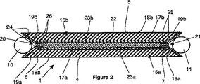
- 大型ベース(18a、18b)と鋭角を形成する少なくとも1つの傾斜した平らな側面(19a、19b)によって接続された、相互に平行な平行小型ベース(17a、17b)および前記大型ベース(18a、18b)を各々が備える第1および第2の基本チップ(16a、16b)を備えており、前記第1および第2の基本チップ(16a、16b)が前記小型ベース(17a、17b)によって相互に固定され、前記傾斜した平らな側面(19a、19b)が前記V型または切型V型溝(20、21)を構成する、請求項3に記載のチップ。
- 前記第1および第2の基本チップ(16a、16b)の前記小型ベース(17a、17b)が、前記V型溝(20、21)に平行な追加溝(34a、34b)を備えており、前記第1および第2の基本チップ(16a、16b)の前記追加溝(34a、34b)が、ワイヤ要素(35)用の追加ハウジングを形成するように重ねられる、請求項7に記載のチップ。
- 前記溝が前記後部主面にあり、電気コンタクトが前記チップを介して前記前面から前記凹部まで通過する、請求項4に記載のチップ。
- 前記溝が主面(4,5)にあり、前記チップ(1)を通過する、請求項4に記載のチップ。
- 前記溝の前記側面が爪状に構成される、請求項1乃至10のいずれか一項に記載のチップ。
- 前記溝の両側に切り込みが設けられる、請求項1乃至11のいずれか一項に記載のチップ。
- 各々が2つの収束壁(29a、29b)を備える、V型溝(28)によって分離される複数の基本チップ(16a、16b)を同一ウェーハ(27、33)上に同時に製造し、
前記基本チップ(16a、16b)に一体化されたマイクロエレクトロニクスコンポーネント(23a、23b)と、隣接溝(28)の壁(29a、29b)との間に配置された少なくとも1つのコンタクト(31、32)を各基本チップ(16a、16b)に形成する導電性材料を堆積し、
前記溝(28)が重なるように、前記溝(28)を備える面によって2つのウェーハ(27、33)を組み立て、
前記溝(28)の位置に前記組み立てられたウェーハ(27、33)を切断することを特徴とする請求項1乃至3のいずれか一項に記載のマイクロエレクトロニクスチップ(1)の製造方法。 - 請求項1乃至12のいずれか一項に記載の少なくとも2つのチップを接続する少なくとも1つのワイヤ要素を備える微細構造であって、前記ワイヤ要素が電気接続と、前記2つのチップ間の柔軟性機械的接続の両方を同時に構成する微細構造。
- 前記ワイヤ要素が前記凹部に接着される、請求項14に記載の微細構造。
- 前記ワイヤ要素が前記凹部にはんだ付けされる、請求項14に記載の微細構造。
- 前記ワイヤ要素が前記凹部にクランプされる、請求項14に記載の微細構造。
Applications Claiming Priority (3)
| Application Number | Priority Date | Filing Date | Title |
|---|---|---|---|
| FR0607588A FR2905518B1 (fr) | 2006-08-29 | 2006-08-29 | Puce microelectronique a faces laterales munies de rainures et procede de fabrication |
| FR0607588 | 2006-08-29 | ||
| PCT/FR2007/001034 WO2008025889A1 (fr) | 2006-08-29 | 2007-06-21 | Puce microelectronique nue munie d'un evidement formant un logement pour un element filaire constituant un support mecanique souple, procede de fabrication et microstructure |
Publications (3)
| Publication Number | Publication Date |
|---|---|
| JP2010502030A JP2010502030A (ja) | 2010-01-21 |
| JP2010502030A5 JP2010502030A5 (ja) | 2010-08-12 |
| JP5059110B2 true JP5059110B2 (ja) | 2012-10-24 |
Family
ID=37882559
Family Applications (1)
| Application Number | Title | Priority Date | Filing Date |
|---|---|---|---|
| JP2009526145A Active JP5059110B2 (ja) | 2006-08-29 | 2007-06-21 | 柔軟性機械的サポートを構成するワイヤ要素用ハウジングを形成する凹部を具備するベアマイクロエレクトロニクスチップ、製造プロセスおよび微細構造 |
Country Status (7)
| Country | Link |
|---|---|
| US (1) | US8093617B2 (ja) |
| EP (1) | EP2057687B1 (ja) |
| JP (1) | JP5059110B2 (ja) |
| CN (1) | CN101523605B (ja) |
| ES (1) | ES2539640T3 (ja) |
| FR (1) | FR2905518B1 (ja) |
| WO (1) | WO2008025889A1 (ja) |
Cited By (5)
| Publication number | Priority date | Publication date | Assignee | Title |
|---|---|---|---|---|
| US11755874B2 (en) | 2021-03-03 | 2023-09-12 | Sensormatic Electronics, LLC | Methods and systems for heat applied sensor tag |
| US11769026B2 (en) | 2019-11-27 | 2023-09-26 | Sensormatic Electronics, LLC | Flexible water-resistant sensor tag |
| US11861440B2 (en) | 2019-09-18 | 2024-01-02 | Sensormatic Electronics, LLC | Systems and methods for providing tags adapted to be incorporated with or in items |
| US11869324B2 (en) | 2021-12-23 | 2024-01-09 | Sensormatic Electronics, LLC | Securing a security tag into an article |
| US11928538B2 (en) | 2019-09-18 | 2024-03-12 | Sensormatic Electronics, LLC | Systems and methods for laser tuning and attaching RFID tags to products |
Families Citing this family (25)
| Publication number | Priority date | Publication date | Assignee | Title |
|---|---|---|---|---|
| FR2928491A1 (fr) * | 2008-03-06 | 2009-09-11 | Commissariat Energie Atomique | Procede et dispositif de fabrication d'un assemblage d'au moins deux puces microelectroniques |
| FR2937464B1 (fr) * | 2008-10-21 | 2011-02-25 | Commissariat Energie Atomique | Assemblage d'une puce microelectronique a rainure avec un element filaire sous forme de toron et procede d'assemblage |
| FR2945151B1 (fr) | 2009-04-30 | 2011-04-29 | Commissariat Energie Atomique | Procede de fixation d'un composant electronique sur un produit |
| FR2954588B1 (fr) * | 2009-12-23 | 2014-07-25 | Commissariat Energie Atomique | Procede d'assemblage d'au moins une puce avec un element filaire, puce electronique a element de liaison deformable, procede de fabrication d'une pluralite de puces, et assemblage d'au moins une puce avec un element filaire |
| FR2955972B1 (fr) * | 2010-02-03 | 2012-03-09 | Commissariat Energie Atomique | Procede d'assemblage d'au moins une puce avec un tissu incluant un dispositif a puce |
| JP5640892B2 (ja) * | 2011-05-23 | 2014-12-17 | 三菱電機株式会社 | 半導体装置 |
| FR2978607A1 (fr) | 2011-07-28 | 2013-02-01 | Commissariat Energie Atomique | Procede d'assemblage d'un dispositif a puce micro-electronique dans un tissu, dispositif a puce, et tissu incorporant un dispositif a puce serti |
| FR2986372B1 (fr) * | 2012-01-31 | 2014-02-28 | Commissariat Energie Atomique | Procede d'assemblage d'un element a puce micro-electronique sur un element filaire, installation permettant de realiser l'assemblage |
| CN111676561A (zh) * | 2014-09-30 | 2020-09-18 | 苹果公司 | 具有嵌入式电子部件的织物 |
| CN108235793B (zh) * | 2015-01-27 | 2020-01-07 | 荷兰应用自然科学研究组织Tno | 用于织物层组件的柔性设备模块及生产方法 |
| CN104881694A (zh) * | 2015-05-30 | 2015-09-02 | 宁波慧豪信息产业有限公司 | 一种基于rfid双协议的数据读写方法、终端及系统 |
| US9936595B2 (en) | 2015-11-23 | 2018-04-03 | Thomson Licensing | Wire retention cover for printed circuit boards in an electronic device |
| US10485103B1 (en) | 2016-02-22 | 2019-11-19 | Apple Inc. | Electrical components attached to fabric |
| FR3062237B1 (fr) | 2017-01-23 | 2020-05-01 | Commissariat A L'energie Atomique Et Aux Energies Alternatives | Procede de realisation d’une puce a circuit integre et puce a circuit integre. |
| FR3062515B1 (fr) | 2017-01-30 | 2019-11-01 | Primo1D | Procede d'insertion d'un fil dans une rainure d'une puce de semi-conducteur, et equipement pour la mise en œuvre d’un tel procede. |
| FR3065579B1 (fr) | 2017-04-19 | 2019-05-03 | Primo1D | Dispositif d'emission reception radiofrequence |
| FR3065578B1 (fr) | 2017-04-19 | 2019-05-03 | Primo1D | Procede d'assemblage d'une puce microelectronique sur un element filaire |
| DE102017108580A1 (de) * | 2017-04-21 | 2018-10-25 | Osram Opto Semiconductors Gmbh | Strahlungsemittierendes Halbleiterbauteil und Gewebe |
| WO2018228031A1 (en) * | 2017-06-16 | 2018-12-20 | Guangdong Oppo Mobile Telecommunications Corp., Ltd. | Housing, method for producing the same and mobile terminal |
| CN107148188B (zh) * | 2017-06-16 | 2020-08-07 | Oppo广东移动通信有限公司 | 壳体组件的制备方法、壳体组件和移动终端 |
| FR3076071B1 (fr) | 2017-12-21 | 2019-11-15 | Commissariat A L'energie Atomique Et Aux Energies Alternatives | Procede de fabrication d’une puce a circuit integre et puce a circuit integre |
| FR3078980B1 (fr) | 2018-03-14 | 2021-06-11 | Primo1D | Fil guipe compose d’une ame principale et d’au moins un fils de couverture et comprenant au moins un element filaire conducteur relie electriquement a au moins une puce electronique |
| FR3083643B1 (fr) | 2018-07-04 | 2023-01-13 | Commissariat Energie Atomique | Procede de realisation d'un dispositif electronique |
| US11913143B2 (en) * | 2019-03-08 | 2024-02-27 | Apple Inc. | Fabric with electrical components |
| FR3103630B1 (fr) | 2019-11-22 | 2022-06-03 | Primo1D | Puce fonctionnelle adaptee pour etre assemblee a des elements filaires, et procede de fabrication d’une telle puce |
Family Cites Families (15)
| Publication number | Priority date | Publication date | Assignee | Title |
|---|---|---|---|---|
| JP3211604B2 (ja) * | 1995-02-03 | 2001-09-25 | 株式会社日立製作所 | 半導体装置 |
| JPH10214919A (ja) * | 1997-01-29 | 1998-08-11 | New Japan Radio Co Ltd | マルチチップモジュールの製造方法 |
| JP2002343933A (ja) * | 2001-05-18 | 2002-11-29 | Mitsubishi Electric Corp | 半導体記憶装置 |
| JP3660918B2 (ja) * | 2001-07-04 | 2005-06-15 | 松下電器産業株式会社 | 半導体装置及びその製造方法 |
| JP2003163313A (ja) * | 2001-09-13 | 2003-06-06 | Texas Instr Japan Ltd | 半導体装置及びその製造方法 |
| US6727115B2 (en) | 2001-10-31 | 2004-04-27 | Hewlett-Packard Development Company, L.P. | Back-side through-hole interconnection of a die to a substrate |
| US7144830B2 (en) * | 2002-05-10 | 2006-12-05 | Sarnoff Corporation | Plural layer woven electronic textile, article and method |
| US7485489B2 (en) * | 2002-06-19 | 2009-02-03 | Bjoersell Sten | Electronics circuit manufacture |
| US6646336B1 (en) * | 2002-06-28 | 2003-11-11 | Koninkl Philips Electronics Nv | Wearable silicon chip |
| JP2004288680A (ja) * | 2003-03-19 | 2004-10-14 | Mitsubishi Electric Corp | 圧接型半導体装置 |
| US7716823B2 (en) * | 2004-04-08 | 2010-05-18 | Hewlett-Packard Development Company, L.P. | Bonding an interconnect to a circuit device and related devices |
| US7025596B2 (en) * | 2004-06-14 | 2006-04-11 | Motorola, Inc. | Method and apparatus for solder-less attachment of an electronic device to a textile circuit |
| US20060278997A1 (en) * | 2004-12-01 | 2006-12-14 | Tessera, Inc. | Soldered assemblies and methods of making the same |
| US7675153B2 (en) * | 2005-02-02 | 2010-03-09 | Kabushiki Kaisha Toshiba | Semiconductor device having semiconductor chips stacked and mounted thereon and manufacturing method thereof |
| US20080029879A1 (en) * | 2006-03-01 | 2008-02-07 | Tessera, Inc. | Structure and method of making lidded chips |
-
2006
- 2006-08-29 FR FR0607588A patent/FR2905518B1/fr not_active Expired - Fee Related
-
2007
- 2007-06-21 US US12/310,246 patent/US8093617B2/en active Active
- 2007-06-21 CN CN2007800383632A patent/CN101523605B/zh active Active
- 2007-06-21 WO PCT/FR2007/001034 patent/WO2008025889A1/fr active Application Filing
- 2007-06-21 ES ES07803768.6T patent/ES2539640T3/es active Active
- 2007-06-21 JP JP2009526145A patent/JP5059110B2/ja active Active
- 2007-06-21 EP EP07803768.6A patent/EP2057687B1/fr active Active
Cited By (5)
| Publication number | Priority date | Publication date | Assignee | Title |
|---|---|---|---|---|
| US11861440B2 (en) | 2019-09-18 | 2024-01-02 | Sensormatic Electronics, LLC | Systems and methods for providing tags adapted to be incorporated with or in items |
| US11928538B2 (en) | 2019-09-18 | 2024-03-12 | Sensormatic Electronics, LLC | Systems and methods for laser tuning and attaching RFID tags to products |
| US11769026B2 (en) | 2019-11-27 | 2023-09-26 | Sensormatic Electronics, LLC | Flexible water-resistant sensor tag |
| US11755874B2 (en) | 2021-03-03 | 2023-09-12 | Sensormatic Electronics, LLC | Methods and systems for heat applied sensor tag |
| US11869324B2 (en) | 2021-12-23 | 2024-01-09 | Sensormatic Electronics, LLC | Securing a security tag into an article |
Also Published As
| Publication number | Publication date |
|---|---|
| EP2057687B1 (fr) | 2015-04-22 |
| FR2905518B1 (fr) | 2008-12-26 |
| US8093617B2 (en) | 2012-01-10 |
| ES2539640T3 (es) | 2015-07-02 |
| CN101523605A (zh) | 2009-09-02 |
| JP2010502030A (ja) | 2010-01-21 |
| CN101523605B (zh) | 2012-07-11 |
| WO2008025889A1 (fr) | 2008-03-06 |
| EP2057687A1 (fr) | 2009-05-13 |
| FR2905518A1 (fr) | 2008-03-07 |
| US20090200066A1 (en) | 2009-08-13 |
Similar Documents
| Publication | Publication Date | Title |
|---|---|---|
| JP5059110B2 (ja) | 柔軟性機械的サポートを構成するワイヤ要素用ハウジングを形成する凹部を具備するベアマイクロエレクトロニクスチップ、製造プロセスおよび微細構造 | |
| JP5405457B2 (ja) | フレキシブルな接続によって機械的に相互接続された複数のチップからなるセットを生成する方法 | |
| US5821762A (en) | Semiconductor device, production method therefor, method for testing semiconductor elements, test substrate for the method and method for producing the test substrate | |
| CN100433292C (zh) | 集成结构及其制造方法 | |
| JP4485790B2 (ja) | 微小電気機械部品を製造するためのプロセス | |
| JP5433899B2 (ja) | 3次元電子モジュールの集合的製作方法 | |
| CA2347568C (en) | Circuit board and method of manufacturing a circuit board | |
| JP5340398B2 (ja) | 半導体コンポーネント用の担体、半導体コンポーネントおよび担体の製造方法 | |
| CN102971841A (zh) | 在柔性基板中组装芯片的方法 | |
| JP2008546174A5 (ja) | ||
| CN102105894B (zh) | 具有多个部件的芯片卡 | |
| JP2008102315A (ja) | 光接続部品の製造方法および光接続部品 | |
| CN107579342A (zh) | 射频发射/接收元件和制造射频发射/接收元件的方法 | |
| KR20150099535A (ko) | 후면 상에 콘택을 가진 광전지를 상호연결하기 위한 장치 및 그러한 장치를 포함하는 모듈 | |
| US20090095974A1 (en) | Semiconductor package and manufacturing method thereof | |
| EP1624478A2 (en) | Substrate, semiconductor device, method of manufacturing substrate, and method of manufacturing semiconductor device | |
| JP2001007403A (ja) | 並列伝送型光モジュールおよびその製造方法 | |
| JP6957599B2 (ja) | 発光デバイス及びその製造方法 | |
| KR100962602B1 (ko) | 전기적 접촉장치 및 그 제조방법 | |
| JP2001203427A (ja) | 波長多重面型発光素子装置、その製造方法およびこれを用いた波長多重伝送システム | |
| CN105226013B (zh) | 多孔状绝缘介质层的三维互连装置及其制备方法 | |
| TW201431128A (zh) | 發光元件及其製作方法 | |
| CN100401488C (zh) | 具有小回路高度的接线连接的片状模块 | |
| CN216213375U (zh) | 载体基板、分离设备及存储器装置 | |
| WO2020046119A1 (en) | Electronic device and method of manufacturing the same |
Legal Events
| Date | Code | Title | Description |
|---|---|---|---|
| A521 | Request for written amendment filed |
Free format text: JAPANESE INTERMEDIATE CODE: A523 Effective date: 20091225 |
|
| A521 | Request for written amendment filed |
Free format text: JAPANESE INTERMEDIATE CODE: A523 Effective date: 20100531 |
|
| A621 | Written request for application examination |
Free format text: JAPANESE INTERMEDIATE CODE: A621 Effective date: 20100601 |
|
| AA91 | Notification that invitation to amend document was cancelled |
Free format text: JAPANESE INTERMEDIATE CODE: A971091 Effective date: 20100629 |
|
| A977 | Report on retrieval |
Free format text: JAPANESE INTERMEDIATE CODE: A971007 Effective date: 20120627 |
|
| TRDD | Decision of grant or rejection written | ||
| A01 | Written decision to grant a patent or to grant a registration (utility model) |
Free format text: JAPANESE INTERMEDIATE CODE: A01 Effective date: 20120703 |
|
| A01 | Written decision to grant a patent or to grant a registration (utility model) |
Free format text: JAPANESE INTERMEDIATE CODE: A01 |
|
| A61 | First payment of annual fees (during grant procedure) |
Free format text: JAPANESE INTERMEDIATE CODE: A61 Effective date: 20120801 |
|
| FPAY | Renewal fee payment (event date is renewal date of database) |
Free format text: PAYMENT UNTIL: 20150810 Year of fee payment: 3 |
|
| R150 | Certificate of patent or registration of utility model |
Ref document number: 5059110 Country of ref document: JP Free format text: JAPANESE INTERMEDIATE CODE: R150 Free format text: JAPANESE INTERMEDIATE CODE: R150 |
|
| R250 | Receipt of annual fees |
Free format text: JAPANESE INTERMEDIATE CODE: R250 |
|
| R250 | Receipt of annual fees |
Free format text: JAPANESE INTERMEDIATE CODE: R250 |
|
| R250 | Receipt of annual fees |
Free format text: JAPANESE INTERMEDIATE CODE: R250 |
|
| R250 | Receipt of annual fees |
Free format text: JAPANESE INTERMEDIATE CODE: R250 |
|
| R250 | Receipt of annual fees |
Free format text: JAPANESE INTERMEDIATE CODE: R250 |
|
| R250 | Receipt of annual fees |
Free format text: JAPANESE INTERMEDIATE CODE: R250 |
|
| R250 | Receipt of annual fees |
Free format text: JAPANESE INTERMEDIATE CODE: R250 |
|
| R250 | Receipt of annual fees |
Free format text: JAPANESE INTERMEDIATE CODE: R250 |
|
| R250 | Receipt of annual fees |
Free format text: JAPANESE INTERMEDIATE CODE: R250 |
|
| R250 | Receipt of annual fees |
Free format text: JAPANESE INTERMEDIATE CODE: R250 |