JP3649843B2 - 車両用座席のヒンジ機構およびそのヒンジ機構を含む座席 - Google Patents
車両用座席のヒンジ機構およびそのヒンジ機構を含む座席 Download PDFInfo
- Publication number
- JP3649843B2 JP3649843B2 JP04279897A JP4279897A JP3649843B2 JP 3649843 B2 JP3649843 B2 JP 3649843B2 JP 04279897 A JP04279897 A JP 04279897A JP 4279897 A JP4279897 A JP 4279897A JP 3649843 B2 JP3649843 B2 JP 3649843B2
- Authority
- JP
- Japan
- Prior art keywords
- side plate
- hinge mechanism
- teeth
- control shaft
- side plates
- Prior art date
- Legal status (The legal status is an assumption and is not a legal conclusion. Google has not performed a legal analysis and makes no representation as to the accuracy of the status listed.)
- Expired - Fee Related
Links
- 230000007246 mechanism Effects 0.000 title claims description 47
- 239000002893 slag Substances 0.000 claims description 9
- 239000002184 metal Substances 0.000 description 10
- 241000237858 Gastropoda Species 0.000 description 3
- 230000003796 beauty Effects 0.000 description 1
- 238000010586 diagram Methods 0.000 description 1
- 238000006073 displacement reaction Methods 0.000 description 1
Images
Classifications
-
- B—PERFORMING OPERATIONS; TRANSPORTING
- B60—VEHICLES IN GENERAL
- B60N—SEATS SPECIALLY ADAPTED FOR VEHICLES; VEHICLE PASSENGER ACCOMMODATION NOT OTHERWISE PROVIDED FOR
- B60N2/00—Seats specially adapted for vehicles; Arrangement or mounting of seats in vehicles
- B60N2/02—Seats specially adapted for vehicles; Arrangement or mounting of seats in vehicles the seat or part thereof being movable, e.g. adjustable
- B60N2/20—Seats specially adapted for vehicles; Arrangement or mounting of seats in vehicles the seat or part thereof being movable, e.g. adjustable the back-rest being tiltable, e.g. to permit easy access
-
- B—PERFORMING OPERATIONS; TRANSPORTING
- B60—VEHICLES IN GENERAL
- B60N—SEATS SPECIALLY ADAPTED FOR VEHICLES; VEHICLE PASSENGER ACCOMMODATION NOT OTHERWISE PROVIDED FOR
- B60N2/00—Seats specially adapted for vehicles; Arrangement or mounting of seats in vehicles
- B60N2/02—Seats specially adapted for vehicles; Arrangement or mounting of seats in vehicles the seat or part thereof being movable, e.g. adjustable
- B60N2/22—Seats specially adapted for vehicles; Arrangement or mounting of seats in vehicles the seat or part thereof being movable, e.g. adjustable the back-rest being adjustable
- B60N2/225—Seats specially adapted for vehicles; Arrangement or mounting of seats in vehicles the seat or part thereof being movable, e.g. adjustable the back-rest being adjustable by cycloidal or planetary mechanisms
- B60N2/2252—Seats specially adapted for vehicles; Arrangement or mounting of seats in vehicles the seat or part thereof being movable, e.g. adjustable the back-rest being adjustable by cycloidal or planetary mechanisms in which the central axis of the gearing lies inside the periphery of an orbital gear, e.g. one gear without sun gear
-
- B—PERFORMING OPERATIONS; TRANSPORTING
- B60—VEHICLES IN GENERAL
- B60N—SEATS SPECIALLY ADAPTED FOR VEHICLES; VEHICLE PASSENGER ACCOMMODATION NOT OTHERWISE PROVIDED FOR
- B60N2/00—Seats specially adapted for vehicles; Arrangement or mounting of seats in vehicles
- B60N2/02—Seats specially adapted for vehicles; Arrangement or mounting of seats in vehicles the seat or part thereof being movable, e.g. adjustable
- B60N2/22—Seats specially adapted for vehicles; Arrangement or mounting of seats in vehicles the seat or part thereof being movable, e.g. adjustable the back-rest being adjustable
- B60N2/235—Seats specially adapted for vehicles; Arrangement or mounting of seats in vehicles the seat or part thereof being movable, e.g. adjustable the back-rest being adjustable by gear-pawl type mechanisms
- B60N2/2356—Seats specially adapted for vehicles; Arrangement or mounting of seats in vehicles the seat or part thereof being movable, e.g. adjustable the back-rest being adjustable by gear-pawl type mechanisms with internal pawls
- B60N2/2358—Seats specially adapted for vehicles; Arrangement or mounting of seats in vehicles the seat or part thereof being movable, e.g. adjustable the back-rest being adjustable by gear-pawl type mechanisms with internal pawls and provided with memory locks
Landscapes
- Engineering & Computer Science (AREA)
- Aviation & Aerospace Engineering (AREA)
- Transportation (AREA)
- Mechanical Engineering (AREA)
- Chairs For Special Purposes, Such As Reclining Chairs (AREA)
- Seats For Vehicles (AREA)
Description
【発明の属する技術分野】
本発明は、車両用座席のヒンジ機構およびそのヒンジ機構を含む車両用座席に関するものであり、各ヒンジ機構は互いに枢動自在に取り付けられた2つの部分を示している。
【0002】
問題のヒンジ機構は、特に自動車の前座席に取り付けることができる。
【0003】
このようなヒンジ機構の中、本発明は、特に、
・互いに回転可能な第1側板および第2側板と;
・互いに噛合い、それぞれ第1側板および第2側板と機械的に連結された第1円形の内歯の組および第1円形の外歯の組を有し、第1の内歯の組と第1の外歯の組との間の回転が第1側板と第2側板との間の対応する回転に対応し、これら二つの歯の組が、互いに平行でオフセットしていて、それぞれ第1軸線および第2軸線と称されるそれぞれの中心軸線を有する、内転サイクロイド型歯車装置と;
・第1軸線の周りに回転して第1の内歯の組と第1の外歯の組との間の相対回転を生ずるように取り付けられた第1カム;並びに
・第1カムを回転させるための第1制御軸;
を含むヒンジ機構に関する。
【0004】
【従来の技術】
そのようなヒンジ機構の例は、特にヨーロッパ特許明細書A−0505229に記載されている。
【0005】
そのようなヒンジ機構により、座席の調節を非常に精密に行うことができるが、その制御のもとで座席の可動部分を比較的ゆっくりとしか動すことができないので、その結果可動部分を長い行程に亘って動かすためにはかなり長い時間を要する。
【0006】
その上、このヒンジ機構を手で動かすとき、使用者が座席の可動部をそのような長い行程に亘って動かすのは疲れる。
【0007】
【発明が解決しようとする課題】
本発明の目的は、特に、これらの欠点を軽減することである。
【0008】
【課題を解決するための手段】
この目的のため、本発明は、問題の種類のヒンジ機構で本質的に更に:
・上述の第1軸線および第2軸線のうちの一方の周りにこの第2側板に対して回転するように取り付けられた第3側板であって、これら三つの側板が上記軸線に垂直な平面と平行に延在し、第2側板が第1側板と第3側板との間に配置されており、第2側板と第3側板のうちの一つが、第3側板の回転軸線と中心を同じくする円弧に沿って少なくとも延びている半径方向内方に向いた歯の組を備え、第1側板および第3側板が、それぞれ、座席の上述の部分に固着可能である第3側板;
・上述の内方に向いた歯の組と協同するのに適した外方を向いた歯の組を備える少なくとも一つのスラグ(slug)であって、このスラグがこの第2側板と第3側板のうちの内方に向いた歯の組に固着されていないものに固着された少なくとも一つの案内によって半径方向に滑動するように案内され、また、内方に向いた歯の組と協同して第2側板と第3側板との間の相対回転を阻止する係合位置と、内方に向いた歯の組と協同しない引っ込み位置との間を変位可能であるスラグ;
・このスラグの滑動を制御するための第2カムであって、スラグを係合位置に置く弾性手段によって休止位置の方へ押し付けられている第2カム;並びに
・この第2カムを休止位置からスラグが引っ込み位置の方へ滑動できる作動位置の方へ動かすための制御部材;
を含むことを特徴とするヒンジ機構を提供する。
【0009】
【発明の効果】
このような配置によって、座席の使用者がヒンジ機構の支配下の座席可動部分を長い行程に亘って動かそうとするときは、第2カム用制御部材を作動させ、それによって第2側板および第3側板を互いに自由に回転できるようにするだけで十分である。すると、使用者は、関係する可動部に直接力を加えることによって座席を調整することができる。
【0010】
対照的に、座席を微調整するためには、第1制御軸を作動させ、内転サイクロイド型歯車装置によって第1側板と第2側板とを相対回転させる。
【0011】
【発明の実施の形態】
本発明のヒンジ機構の好適実施例においては、以下の配置の幾つかも使用する:
・この第1の内歯の組および第1の外歯の組のうちの一方の組が第1側板に固着され、他方の組が第2側板に固着されている;
・第1の外歯の組が、この第1の外組の歯の直径とは異なる直径の第2の円形外歯の組も含むリング歯車に固着されており、この第2の円形外歯の組は第2の円形内歯の組と係合しており、第1の内歯の組と第2の内歯の組のうちの一方の組が第1側板に固着されており、他方の組が第2側板に固着されている;
・第2カムが第3側板の回転軸線の周りに回転するように取り付けられており、この第2カムの制御部材が第3側板の回転軸線に沿って長手方向に延びる第2制御軸である;
・第1制御軸および第2制御軸の一方が中空であって、他方を収容している;
・第2制御軸が中空であって、第1制御軸を収容しており、この第1制御軸が制御ノブに固着されており、第2制御軸が、制御ノブと側板との間を制御ノブの外周のすぐ外まで半径方向外方に延びているハンドルに固着されている;
・第1制御軸および第2制御軸が反対方向に延びている;並びに
・内方を向いた歯の組が第2側板に固着されており、一方スラグ用案内が第3側板に固着されている。
【0012】
本発明は、上述のヒンジ機構によって、互いに枢動するように取り付けられた二つの部分、特に座席本体および背もたれ、を含む車両用座席を提供する。これら二つの部分のうちの一方が第1側板に固着されており、他方が第3側板に固着されている。
【0013】
【実施例】
本発明のその他の特徴および利点は、非限定的例として挙げ、添付の図面を参照する以下の種々の実施例の説明から明白となる。
【0014】
種々の図面で、同じ参照番号は同一または類似の要素を示す。
【0015】
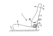
図1は、自動車の前部座席1の略図であり、座席1は第1に車両の床3に取り付けられた座席本体(seat proper)2と、第2に座席本体2に対して水平横軸線Xの周りに枢動するように取り付けられた背もたれ4とを有する。
【0016】
この様にして、背もたれ4は、ヒンジ機構6によって、両頭矢印5で示す方向に沿って前後に変位可能である。ヒンジ機構の第1実施例が図2から図5までに示されている。
【0017】
ヒンジ機構6は:
・ほぼ円形で、軸線X(すなわち第1軸線)に垂直な平面内に延在し、図示の例では、座席本体の骨組2aに固着された第1金属側板7;
・形状が同様に円形で、第1金属側板7に平行に延在し、軸線Xの周りに回転するように取り付けられた第2金属側板8;
・形状が円形で、最初の二つの側板に平行に延在し、第2側板8を第1側板7との間に狭持し、図示の例では、この背もたれの骨組4aに固定された第3金属側板9;
・第1側板7および第3側板9の外周を囲み、それらと協同して閉じた箱を形成する内方に開いた溝形断面の金属帯10;
・第1側板と第2側板との間に配置された内転サイクロイド型歯車装置11;並びに
・第2側板と第3側板との間に配置されたロック機構12;
を含む。
【0018】
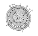
まず第1に、従来通りに、この内転サイクロイド型歯車装置11は、次のものを含む:
・X軸線に垂直な平面内に延在し、この軸線に対して偏心している円形の金属製第1カム13;
・第1側板7を通って軸線Xに沿って長手方向に延び、第1カム13に固着されている第1制御軸14であって、図示の例ではその端に固定された制御ノブ15を手動で廻すことによって作動する第1制御軸14;並びに
・二つの外歯の組を有し、第1カム13に回転自在に取り付けられたリング歯車16であって、第1カムの軸線(すなわち第2軸線)13aに中心を置く第1円形外歯の組17と、同様に第1カムの軸線13aに中心を置くが、第1の外歯の組17より直径が小さい第2円形外歯の組18とを有するリング歯車16。
【0019】
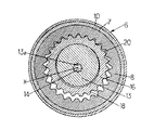
リング歯車の第1外歯の組17は、第1側板7の第1円形内歯の組19と係合しており、また、リング歯車の第2外歯の組18は、第2側板8の第2円形内歯の組20と係合しており、内歯の両組19、20とも、X軸線を中心としている。
【0020】
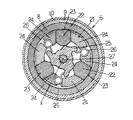
また、ロック機構12も、同様に従来通り以下のものを含む:
・第2側板8に属し、好ましくはX軸線を中心とし(または任意に、このX軸線および軸線13aとは異なる第3の軸線を中心とし)、第2側板の第3側板9に向いた面に作られている、内方に向いた円形歯の組21;
・三つの金属スラグ22であって、各々が第2側板の内方に向いた歯の組21と係合するのに適した外方に向いた歯の組23を有し、第3側板に属する突起24によって半径方向に滑動するように案内されている三つの金属スラグ22;
・X軸線周りに回転可能で、スラグ22と同じ半径方向平面内に配置された打抜き金属板でありカム静止位置とカム作動位置との間を角度的に変位可能な第2カム25であって、カム静止位置ではカム25はスラグをスラグの外方に向いた歯23が第2側板の内方に向いた歯21と協同する係合位置の方へ押しやり、カム作動位置では第2カムがスラグ22をスラグの外方に向いた歯の組23が第2側板の内方に向いた歯21ともはや協同しない引っ込んだ位置の方へ戻れるようにしている第2カム25;
・第2カムをその静止位置の方へ押し付ける三つの金属ばね26;並びに
・第2カム25に固着されており、第3側板9を通ってX軸線に沿って長手方向に延在している第2制御軸27。
【0021】
図示の例では、第2制御軸27が半径方向レバー28に固着されている。レバー28の自由端がハンドル29によって軸線方向に延びており、そのハンドルは、背もたれ4の骨組4aに作られた弓形溝孔30を通ってこの背もたれの外に突出している。
【0022】
この配置により、制御ノブ15を手動で廻すことによって、背もたれの傾斜の微調整をすることが可能であり、またハンドル29を操作することによって、背もたれが自由に枢動できるようになり、それによって背もたれの大きな角度的変位を迅速且つ容易にできる。
【0023】
図6に示す変形例では、ヒンジ機構6が、以下の点だけが図2および図5に示す機構とは異なる:
・第1側板7が背もたれの骨組4aに固着されており、第3側板9が座席本体の骨組2aに固着されており、第3側板は座席の外側に向けて配置されている;
・第2カム25の第2制御軸27aを中心孔が貫通しており、この第2制御軸が第3側板9およびこの座席本体の骨組2aを通って座席の外側の方に延びている;
・第1カム13の第1制御軸14が、第1側板7ではなくて、上述の第2制御軸27aの中心孔を通ってこの座席の外側の方に延びている;並びに
・レバー28が制御ノブ15と座席本体の骨組2aとの間を制御ノブ15の外周のすぐ外まで半径方向外方に延びている。
【0024】
本発明の第2実施例(図7)では、ヒンジ機構6が、以下の点で図2から図5までのヒンジ機構とは異なる:
・内転サイクロイド型歯車装置11にリング歯車16がなく、第1円形外歯17が第2側板8に固着されており、第2側板が第1カム13に回転自在に取り付けられている;および
・第2側板8、第3側板9、第1円形内歯の組21、第2カム25、および第2制御軸27が全て、X軸線ではなく、第1カムの軸線13aを中心としている。
【0025】
この後者の実施例では、制御ノブ15を回転すると、第2側板8および第3側板9がX軸線周りに章動運動しながら回転する。
【図面の簡単な説明】
【図1】 本発明のヒンジ機構を取り付けた座席の概略図である。
【図2】 図1の座席に取り付けるのに適したヒンジ機構の第1実施例の軸線方向断面図で、このヒンジ機構はリング歯車を備える内転サイクロイド型歯車装置を含む。
【図3】 図2のIII−III 線による断面図である。
【図4】 図2のIV−IV 線による断面図である。
【図5】 図2のV−V 線による断面図である。
【図6】 図2から図5までに示された機構に類似するが、異なる配置の制御手段を含むヒンジ機構の軸線方向断面図である。
【図7】 本発明の第2実施例によるヒンジ機構の軸線方向断面図で、このヒンジ機構がリング歯車なしの内転サイクロイド型歯車装置を含む。
【符号の説明】
1 車両用座席
2 座席本体
4 背もたれ
6 ヒンジ機構
7 第1側板
8 第2側板
9 第3側板
11 内転サイクロイド型歯車装置
13 第1カム
13a 第2軸線
14 第1制御軸
15 制御ノブ
16 リング歯車
17 第1円形外歯の組
18 第2円形外歯の組
19 第1円形内歯の組
20 第2円形内歯の組
21 内方に向いた歯
22 スラグ
23 外方に向いた歯
24 案内
25 第2カム
26 弾性手段
27 制御部材(第2制御軸)
27a 制御部材(第2制御軸)
28 ハンドル
29 ハンドル
Claims (10)
- 互いに枢動するように取り付けられた2つの部分(2,4)を有する車両用座席(1)のためのヒンジ機構(6)において、
互いに対して回転可能な第1および第2の平行な側板(7,8)と、
前記第1および第2の平行な側板(7,8)の間に配置された内転サイクロイド型歯車装置(11)であって、互いに噛合う第1の円形の内歯の組(19)と第1の円形の外歯の組(17)とを少なくとも含み、前記第1の内歯の組(19)の第1の中心軸線(X)と前記第1の外歯の組(17)の第2の中心軸線(13a)とが、互いに平行であり且つオフセットされている内転サイクロイド型歯車装置(11)と、
前記第1軸線(X)の周りで回転して前記第1の円形の内歯の組(19)と前記第1の円形の外歯の組(17)との間の相対回転を生ずるように取り付けられた第1カム(13)と、
前記第1および第2の側板(7,8)に平行な第3の側板(9)であって、前記第1および第2の軸線(X,13a)のうちの1つの周りで前記第2の側板(8)に対して回転するように取り付けられており、前記第2の側板が前記第1および第3の側板(7,9)の間に配置される第3の側板(9)と、
前記第2および第3の側板(8,9)を互いに固定し、あるいは前記第2および第3の側板(8,9)の間の相対回転を可能にするようになっているロック機構(12)であって、前記ロック機構(12)が、外方に向いた歯の組(23)を備えた少なくとも1つのスラグ(22)と、少なくとも円弧に沿って延びている内方に向いた歯の組(21)とを含み、前記スラグ(22)は第2カム(25)によって作動されて、前記外方に向いた歯の組(23)が前記内方に向いた歯の組(21)と噛合って前記第2および第3の側板(8,9)の間の相対回転を阻止する係合位置と、前記外方に向いた歯の組(23)が前記内方に向いた歯の組(21)と噛合わない引っ込み位置との間で動かされ、前記第1および第3の側板(7,9)が前記座席の2つの部分(2,4)に固着可能であるロック機構(12)と
を有するヒンジ機構(6)。 - 前記第1の円形の内歯の組(19)および前記第1の円形の外歯の組(17)が、前記第1および第2の側板(7,8)にそれぞれ固定されている請求項1に記載のヒンジ機構。
- 前記内転サイクロイド型歯車装置(11)が、前記第1の円形の外歯の組(17)を含むリング歯車(16)を有し、
該リング歯車(16)が、前記第1の円形の外歯の組(17)の直径とは異なる直径の第2の円形の外歯の組(18)をさらに含み、且つ前記第2側板(8)に固定された第2の円形の内歯の組(20)と係合し、
前記第1の円形の内歯の組(19)が前記第1側板(7)に固定されている請求項1に記載のヒンジ機構。 - 前記第2カム(25)が前記第3の側板(9)の回転軸線(X,13a)の周りで回転するように取り付けられ、前記第1カム(13)が第1制御軸(14)によって制御され、前記第2カムが、前記第3の側板(9)の回転軸線(x,13a)に沿って長手方向に延びる第2制御軸(27,27a)によって制御される請求項1から請求項3までのいずれか1項に記載のヒンジ機構。
- 前記第1制御軸および前記第2制御軸のうちの一方(27a)が中空であり且つ他方(14)を収容している請求項4に記載のヒンジ機構。
- 前記第2制御軸(27a)が中空であり且つ前記第1制御軸(14)を収容し、前記第1制御軸(14)が制御ノブ(15)に固着され、前記第2制御軸(27a)が、前記制御ノブ(15)と前記側板(7,8,9)の間で前記制御ノブの外周のすぐ外まで半径方向外方に延びているハンドル(28,29)に固着されている請求項5 に記載のヒンジ機構。
- 前記第1制御軸および前記第2制御軸(14,27)が反対方向に延びている請求項4に記載のヒンジ機構。
- 前記内方に向いた歯の組(21)が前記第2側板(8)に固着され、前記スラグ(22)が、前記第3側板(9)に固着された半径方向案内(24)によって滑動するように案内される請求項1から請求項7までのいずれか1項に記載のヒンジ機構。
- 請求項1から請求項8までのいずれか1項に記載のヒンジ機構(6)によって互いに枢動するように取り付けられた2つの部分(2,4)を有する車両用座席(1)であって、前記2つの部分のうちの一方が前記第1側板(7)に固着され、他方が前記第3側板(9)に固着されている車両用座席。
- 前記ヒンジ機構(6)によって互いに枢動するように取り付けられた前記2つの部分が、座席本体(2)および背もたれ(4)から構成されている請求項9に記載の車両用座席。
Applications Claiming Priority (2)
| Application Number | Priority Date | Filing Date | Title |
|---|---|---|---|
| FR9600659 | 1996-01-22 | ||
| FR9600659A FR2743764B1 (fr) | 1996-01-22 | 1996-01-22 | Mecanisme d'articulation pour siege de vehicule, et siege comportant un tel mecanisme |
Publications (2)
| Publication Number | Publication Date |
|---|---|
| JPH09313285A JPH09313285A (ja) | 1997-12-09 |
| JP3649843B2 true JP3649843B2 (ja) | 2005-05-18 |
Family
ID=9488310
Family Applications (1)
| Application Number | Title | Priority Date | Filing Date |
|---|---|---|---|
| JP04279897A Expired - Fee Related JP3649843B2 (ja) | 1996-01-22 | 1997-01-22 | 車両用座席のヒンジ機構およびそのヒンジ機構を含む座席 |
Country Status (6)
| Country | Link |
|---|---|
| US (1) | US5755491A (ja) |
| JP (1) | JP3649843B2 (ja) |
| KR (1) | KR970058986A (ja) |
| BR (1) | BR9700729A (ja) |
| DE (1) | DE19702123A1 (ja) |
| FR (1) | FR2743764B1 (ja) |
Cited By (1)
| Publication number | Priority date | Publication date | Assignee | Title |
|---|---|---|---|---|
| US11702211B2 (en) | 2021-04-15 | 2023-07-18 | B/E Aerospace, Inc. | Headrest tilt mechanism utilizing gear reduction |
Families Citing this family (66)
| Publication number | Priority date | Publication date | Assignee | Title |
|---|---|---|---|---|
| JP3295318B2 (ja) * | 1996-11-12 | 2002-06-24 | 本田技研工業株式会社 | 車両用シート装置 |
| DE19725899C2 (de) | 1997-06-13 | 1999-10-28 | Brose Fahrzeugteile | Beidseitig wirkender Verstellantrieb |
| CA2243166C (en) * | 1997-07-15 | 2006-02-07 | Magna Lomason Corporation | Ring type recliner |
| FR2766137B1 (fr) * | 1997-07-15 | 1999-10-01 | Faure Bertrand Equipements Sa | Siege de vehicule equipe d'un mecanisme d'articulation |
| FR2766138B1 (fr) * | 1997-07-17 | 1999-10-01 | Faure Bertrand Equipements Sa | Mecanisme d'articulation pour siege de vehicule, et siege de vehicule equipe d'un tel mecanisme |
| JPH1146914A (ja) * | 1997-08-08 | 1999-02-23 | Ikeda Bussan Co Ltd | 両側リクライニング装置 |
| FR2770810B1 (fr) * | 1997-11-07 | 2000-01-14 | Faure Bertrand Equipements Sa | Mecanisme d'articulation pour siege de vehicule, et siege de vehicule comportant un tel mecanisme |
| DE19755336C1 (de) * | 1997-12-15 | 1999-05-06 | Faure Bertrand Sitztech Gmbh | Fahrzeugsitz mit vorklappbarer Rückenlehne |
| FR2777837B1 (fr) * | 1998-04-27 | 2000-07-07 | Faure Bertrand Equipements Sa | Mecanisme d'articulation pour siege de vehicule, et siege de vehicule equipe d'un tel mecanisme |
| FR2781436B1 (fr) * | 1998-07-24 | 2000-09-22 | Cesa | Siege pour vehicule automobile a dossier rabattable |
| US6168235B1 (en) | 1998-11-16 | 2001-01-02 | Dura Global Technologies Inc. | Recliner control mechanism for a seat assembly |
| DE19855004C5 (de) | 1998-11-20 | 2006-12-28 | Brose Fahrzeugteile Gmbh & Co. Kommanditgesellschaft, Coburg | Antrieb für Verstellvorrichtungen in Kraftfahrzeugen |
| FR2786446B1 (fr) * | 1998-12-01 | 2001-02-16 | Faure Bertrand Equipements Sa | Siege de vehicule comportant un mecanisme d'articulation |
| DE19858980C5 (de) * | 1998-12-19 | 2004-04-29 | Keiper Gmbh & Co. Kg | Fahrzeugsitz, insbesondere Kraftfahrzeugsitz, mit einer Einstellvorrichtung |
| DE19904299C1 (de) * | 1999-01-28 | 2000-06-08 | Keiper Gmbh & Co | Rastbeschlag für einen Fahrzeugsitz |
| FR2790230B1 (fr) * | 1999-02-25 | 2002-05-24 | Faure Bertrand Equipements Sa | Mecanisme d'articulation pour siege de vehicule et siege equipe d'un tel mecanisme |
| FR2795689B1 (fr) * | 1999-07-02 | 2001-10-05 | Faure Bertrand Equipements Sa | Dispositif de verrouillage pour siege de vehicule, et siege comportant un tel dispositif |
| US6312053B1 (en) | 1999-07-20 | 2001-11-06 | Magna Interior Systems, Inc. | Recliner assembly |
| US6149235A (en) * | 1999-08-13 | 2000-11-21 | Lear Corporation | Rotary-cam type reclining device |
| DE19952633C1 (de) | 1999-10-21 | 2001-09-13 | Brose Fahrzeugteile | Beidseitig wirkender Antrieb für Verstellvorrichtungen in Kraftfahrzeugen |
| FR2806982B1 (fr) * | 2000-03-30 | 2002-06-14 | Faurecia Sieges Automobile | Mecanisme d'articulation pour siege de vehicule et siege equipe d'un tel mecanisme |
| FR2806981B1 (fr) * | 2000-03-30 | 2002-06-14 | Faure Bertrand Equipements Sa | Mecanisme d'articulation pour siege de vehicule et siege equipe d'un tel mecanisme |
| DE10033666C2 (de) * | 2000-07-11 | 2003-02-20 | Faurecia Autositze Gmbh & Co | Verstellbeschlag für einen Kraftfahrzeugsitz,insb.Neigungsverstellbeschlag für dessen Rückenlehne |
| DE60107952T2 (de) | 2000-07-13 | 2005-12-15 | Intier Automotive Inc., Aurora | Kompakte neigungsverstellvorrichtung für einen fahrzeugsitz |
| AT409711B (de) * | 2000-08-07 | 2002-10-25 | Schukra Geraetebau Ag | Vorrichtung zum lageverändern und feststellen von teilen, z.b. lordosenstützen, von möbeln zum sitzen und/oder liegen |
| US6520583B1 (en) | 2000-08-24 | 2003-02-18 | Fisher Dynamics Corporation | Compact disc recliner |
| DE60109794T2 (de) | 2000-09-29 | 2006-02-23 | Intier Automotive Inc., Aurora | Neigungsversteller mit planetarscheibengetriebe |
| JP4736170B2 (ja) * | 2000-10-13 | 2011-07-27 | アイシン精機株式会社 | リクライニング装置 |
| US6652031B2 (en) | 2001-01-19 | 2003-11-25 | Intier Automotive Inc. | Recliner assembly having a shaft with an annular recess |
| DE10307255B4 (de) * | 2002-02-21 | 2008-06-12 | Aisin Seiki K.K., Kariya | Sitzvorrichtung |
| JP3934991B2 (ja) * | 2002-05-27 | 2007-06-20 | 日本テクニカ株式会社 | 車輌シートのリクライニング機構 |
| US6910738B2 (en) | 2003-01-28 | 2005-06-28 | Fisher Dynamics Corporation | Device and method for assembling a recliner mechanism |
| US6890034B2 (en) | 2003-01-28 | 2005-05-10 | Fisher Dynamics Corporation | Compact recliner with locking cams |
| GB2404233A (en) * | 2003-07-22 | 2005-01-26 | Johnson Controls Automotive Uk | Adjustment mechanism |
| TWI249482B (en) * | 2003-09-10 | 2006-02-21 | Aisin Seiki | Angular position adjusting mechanism |
| JP4107249B2 (ja) * | 2004-02-17 | 2008-06-25 | アイシン精機株式会社 | 角度調整機構 |
| US20050168034A1 (en) * | 2004-01-21 | 2005-08-04 | Scott Fast | Disc recliner with dual cams |
| US7097253B2 (en) * | 2004-03-11 | 2006-08-29 | Fisher Dynamics Corporation | Round recliner assembly with rear folding latch |
| US7025422B2 (en) * | 2004-03-11 | 2006-04-11 | Fisher Dynamics Corporation | Round recliner assembly with rear folding latch |
| JP4189760B2 (ja) * | 2004-07-28 | 2008-12-03 | アイシン精機株式会社 | リクライニング装置 |
| DE102004049114B4 (de) | 2004-10-07 | 2013-12-24 | Johnson Controls Gmbh | Verstellvorrichtung für eine Fahrzeugkomponente, insbesondere für einen Kraftfahrzeugsitz und Verfahren zur Montage |
| DE102004049991A1 (de) * | 2004-10-14 | 2006-04-20 | Keiper Gmbh & Co.Kg | Beschlag für einen Fahrzeugsitz |
| FR2877283B1 (fr) * | 2004-10-29 | 2007-01-26 | Faurecia Sieges Automobile | Siege escamotable dans le plancher |
| JP4916155B2 (ja) * | 2004-12-28 | 2012-04-11 | デルタ工業株式会社 | リクライニング装置 |
| DE102005058367C5 (de) * | 2005-12-06 | 2012-02-09 | Faurecia Autositze Gmbh | Fahrzeugsitz |
| DK1837229T3 (da) * | 2006-03-22 | 2010-07-26 | Feintool Ip Ag | Hus til et bilsædes hængselbeslag og fremgangsmåde til dets fremstilling |
| DE102006015559B3 (de) * | 2006-04-04 | 2007-08-16 | Keiper Gmbh & Co.Kg | Beschlag für einen Fahrzeugsitz |
| DE102006015558B3 (de) * | 2006-04-04 | 2008-02-14 | Keiper Gmbh & Co.Kg | Beschlag für einen Fahrzeugsitz |
| US7517021B2 (en) * | 2006-09-12 | 2009-04-14 | Lear Corporation | Reclining mechanism for vehicle seats |
| US7513573B2 (en) * | 2006-09-12 | 2009-04-07 | Lear Corporation | Continuous recliner |
| JP2008247187A (ja) * | 2007-03-30 | 2008-10-16 | Aisin Seiki Co Ltd | 車両用シート装置 |
| DE112009000118B4 (de) * | 2008-01-17 | 2014-12-18 | Fisher Dynamics Corp. | Verstellmechanismus und Sitzbaugruppe |
| DE102009005044B4 (de) * | 2009-01-14 | 2025-10-02 | Brose Fahrzeugteile SE & Co. Kommanditgesellschaft, Coburg | Verstellvorrichtung zum Verstellen eines Fahrzeugsitzteils |
| DE102010031119B4 (de) * | 2010-07-08 | 2018-06-14 | Brose Fahrzeugteile Gmbh & Co. Kommanditgesellschaft, Coburg | Rastbeschlag zum Verrasten zweier Fahrzeugteile |
| DE102011004090A1 (de) | 2011-02-14 | 2012-08-16 | Lear Corporation | Sitz-Lehnenvorrichtung mit koaxialer Easy-Entry-Löseeinrichtung |
| DE102011004671A1 (de) | 2011-02-24 | 2012-08-30 | Lear Corporation | Haupt-/Neben-Easy-Entry-Lehnenverstellvorrichtung |
| CN104185570B (zh) | 2011-10-06 | 2016-12-07 | 李尔公司 | 具有容易进入型释放的座椅斜倾装置及其制造方法 |
| FR2998228B1 (fr) * | 2012-11-20 | 2014-12-19 | Faurecia Sieges Automobile | Mecanisme de reglage de siege de vehicule automobile |
| FR2998227B1 (fr) * | 2012-11-20 | 2016-05-13 | Faurecia Sieges Automobile | Mecanisme d'articulation de siege automobile |
| US9296315B2 (en) | 2013-02-26 | 2016-03-29 | Fisher & Company, Incorporated | Recliner mechanism with backdriving feature |
| KR101384099B1 (ko) * | 2013-07-04 | 2014-04-10 | 현대다이모스(주) | 차량시트의 힌지장치 |
| US9902297B2 (en) | 2014-06-11 | 2018-02-27 | Fisher & Company, Incorporated | Latch mechanism with locking feature |
| JP6682300B2 (ja) * | 2016-03-04 | 2020-04-15 | シロキ工業株式会社 | シートリクライニング装置 |
| US10611273B2 (en) * | 2017-10-09 | 2020-04-07 | Faurecia Automotive Seating, Llc | Recliner system for a vehicle seat |
| WO2021100554A1 (ja) * | 2019-11-18 | 2021-05-27 | シロキ工業株式会社 | リクライニング装置 |
| KR102348183B1 (ko) * | 2020-04-09 | 2022-01-06 | 황종성 | 엉덩이 및 허리 하중 경감형 의자 |
Family Cites Families (15)
| Publication number | Priority date | Publication date | Assignee | Title |
|---|---|---|---|---|
| DE2641582A1 (de) * | 1976-09-16 | 1978-03-23 | Keiper Automobiltechnik Gmbh | Gelenkbeschlag fuer fahrzeugsitze mit in bezug auf das sitzteil schwenkbarer rueckenlehne |
| US4076309A (en) * | 1977-01-13 | 1978-02-28 | Lear Siegler, Inc. | Seat recliner including adjustment mechanism and latch |
| FR2462127A1 (fr) * | 1979-08-02 | 1981-02-13 | Faure Bertrand | Perfectionnements aux dispositifs d'articulation des dossiers de siege |
| DE3226714C2 (de) * | 1982-07-16 | 1986-09-18 | P.A. Rentrop, Hubbert & Wagner Fahrzeugausstattungen Gmbh & Co Kg, 3060 Stadthagen | Gelenkbeschlag für Kraftfahrzeugsitze mit verstellbarer Lehne |
| DE3560276D1 (en) * | 1984-04-18 | 1987-07-30 | Cousin Cie Ets A & M Freres | Round hinged part for use in seats of land, sea and air vehicles |
| JPS60178438U (ja) * | 1984-05-07 | 1985-11-27 | 白木金属工業株式会社 | 両側リクライニング装置 |
| DE3540727A1 (de) * | 1985-11-16 | 1987-05-21 | Keiper Recaro Gmbh Co | Stellantriebsvorrichtung fuer sitze, insbesondere kraftfahrzeugsitze |
| FR2607761B1 (fr) * | 1986-12-03 | 1990-08-17 | Tubauto | Articulation continue pour siege de vehicule a rattrapage automatique des jeux |
| DE3816833C2 (de) * | 1988-05-18 | 1998-01-15 | Keiper Recaro Gmbh Co | Lehneneinstellbeschlag mit Freischwenkeinrichtung |
| US5277672A (en) * | 1989-06-30 | 1994-01-11 | Ets. Cousin Freres | Clearance take up device for so-called continuous epicycloidal train articulations, and its mounting mode |
| DE3941215C2 (de) * | 1989-12-14 | 1995-07-20 | Keiper Recaro Gmbh Co | Rücklehnenverstellbeschlag für Sitze, insbesondere Kraftfahrzeugsitze |
| US5161856A (en) * | 1990-03-17 | 1992-11-10 | Tachi-S Co., Ltd. | Reclining device for a seat |
| FR2674195B1 (fr) * | 1991-03-19 | 1993-12-17 | Faure Automobile Bertrand | Mecanisme a train hypocyclouidal pour siege de vehicule comportant un frein anti-reversible a couple differentiel. |
| DE4138420C2 (de) * | 1991-09-05 | 2001-03-08 | Faure Bertrand Sitztech Gmbh | Verstellbeschlag für Kraftfahrzeugsitze |
| FR2706380B1 (fr) * | 1993-06-11 | 1995-08-04 | Bfa | Articulation à rattrapage de jeux utilisée dans les sièges automobiles. |
-
1996
- 1996-01-22 FR FR9600659A patent/FR2743764B1/fr not_active Expired - Fee Related
-
1997
- 1997-01-17 US US08/785,631 patent/US5755491A/en not_active Expired - Fee Related
- 1997-01-20 KR KR1019970001451A patent/KR970058986A/ko not_active Withdrawn
- 1997-01-21 BR BR9700729A patent/BR9700729A/pt not_active Application Discontinuation
- 1997-01-22 JP JP04279897A patent/JP3649843B2/ja not_active Expired - Fee Related
- 1997-01-22 DE DE19702123A patent/DE19702123A1/de not_active Withdrawn
Cited By (1)
| Publication number | Priority date | Publication date | Assignee | Title |
|---|---|---|---|---|
| US11702211B2 (en) | 2021-04-15 | 2023-07-18 | B/E Aerospace, Inc. | Headrest tilt mechanism utilizing gear reduction |
Also Published As
| Publication number | Publication date |
|---|---|
| DE19702123A1 (de) | 1997-10-30 |
| US5755491A (en) | 1998-05-26 |
| FR2743764A1 (fr) | 1997-07-25 |
| BR9700729A (pt) | 1998-10-06 |
| KR970058986A (ko) | 1997-08-12 |
| JPH09313285A (ja) | 1997-12-09 |
| FR2743764B1 (fr) | 1998-04-03 |
Similar Documents
| Publication | Publication Date | Title |
|---|---|---|
| JP3649843B2 (ja) | 車両用座席のヒンジ機構およびそのヒンジ機構を含む座席 | |
| JPS6130535Y2 (ja) | ||
| EP2153751B1 (en) | Connection device | |
| KR100840404B1 (ko) | 차량 좌석용 힌지 기구 및 그 힌지 기구를 구비한 좌석 | |
| JP5558110B2 (ja) | 車両シート | |
| JPH1071042A (ja) | シートリクライニング装置 | |
| JP2000316659A (ja) | 乗り物シート用関節機構 | |
| JP2000139599A (ja) | 車両シ―ト組立体および制御組立体 | |
| JP3834937B2 (ja) | 車両用シートリクライニング装置 | |
| JPH0336291Y2 (ja) | ||
| JP2645583B2 (ja) | シートのリクライニング装置 | |
| JPH0819444A (ja) | シートリクライニング装置 | |
| JP2645582B2 (ja) | シートのリクライニング装置 | |
| KR960004072A (ko) | 시트의 헤드 레스트 | |
| JP4461730B2 (ja) | リクライニング装置 | |
| CN113795405A (zh) | 一种用于车辆座椅的调节配件以及车辆座椅 | |
| JP4087505B2 (ja) | 椅子の肘掛け装置 | |
| JPS6041154Y2 (ja) | 継手部材の角度調節兼固定装置 | |
| KR200161785Y1 (ko) | 승용차 좌석의 등받이 각도 조절기구 | |
| JP2667675B2 (ja) | 両側リクライニング装置 | |
| JPH0725074Y2 (ja) | リクライニングアジャスタ操作ノブ | |
| KR0140758Y1 (ko) | 자동차 시이트용 허리받침 조절 손잡이 | |
| JPH0515241Y2 (ja) | ||
| JPH07313295A (ja) | ランバーサポート | |
| JPH0446609Y2 (ja) |
Legal Events
| Date | Code | Title | Description |
|---|---|---|---|
| A131 | Notification of reasons for refusal |
Free format text: JAPANESE INTERMEDIATE CODE: A131 Effective date: 20031212 |
|
| A601 | Written request for extension of time |
Free format text: JAPANESE INTERMEDIATE CODE: A601 Effective date: 20040312 |
|
| A602 | Written permission of extension of time |
Free format text: JAPANESE INTERMEDIATE CODE: A602 Effective date: 20040317 |
|
| A521 | Written amendment |
Free format text: JAPANESE INTERMEDIATE CODE: A523 Effective date: 20040512 |
|
| A131 | Notification of reasons for refusal |
Free format text: JAPANESE INTERMEDIATE CODE: A131 Effective date: 20040910 |
|
| TRDD | Decision of grant or rejection written | ||
| A01 | Written decision to grant a patent or to grant a registration (utility model) |
Free format text: JAPANESE INTERMEDIATE CODE: A01 Effective date: 20050204 |
|
| A61 | First payment of annual fees (during grant procedure) |
Free format text: JAPANESE INTERMEDIATE CODE: A61 Effective date: 20050216 |
|
| R150 | Certificate of patent or registration of utility model |
Free format text: JAPANESE INTERMEDIATE CODE: R150 |
|
| FPAY | Renewal fee payment (event date is renewal date of database) |
Free format text: PAYMENT UNTIL: 20090225 Year of fee payment: 4 |
|
| LAPS | Cancellation because of no payment of annual fees |


