JP2014533878A - 電子回路基板を受け入れるか又は取り囲むハウジングにおいて複数の接触要素に接触する電子回路基板を設置する方法及びハウジング - Google Patents
電子回路基板を受け入れるか又は取り囲むハウジングにおいて複数の接触要素に接触する電子回路基板を設置する方法及びハウジング Download PDFInfo
- Publication number
- JP2014533878A JP2014533878A JP2014542752A JP2014542752A JP2014533878A JP 2014533878 A JP2014533878 A JP 2014533878A JP 2014542752 A JP2014542752 A JP 2014542752A JP 2014542752 A JP2014542752 A JP 2014542752A JP 2014533878 A JP2014533878 A JP 2014533878A
- Authority
- JP
- Japan
- Prior art keywords
- housing
- contact
- circuit board
- electronic circuit
- flexible extension
- Prior art date
- Legal status (The legal status is an assumption and is not a legal conclusion. Google has not performed a legal analysis and makes no representation as to the accuracy of the status listed.)
- Pending
Links
- 238000000034 method Methods 0.000 title claims abstract description 23
- 238000003466 welding Methods 0.000 description 5
- 239000000463 material Substances 0.000 description 2
- 239000002184 metal Substances 0.000 description 2
- 238000005452 bending Methods 0.000 description 1
- 238000007796 conventional method Methods 0.000 description 1
- 230000000694 effects Effects 0.000 description 1
- 239000007769 metal material Substances 0.000 description 1
- 239000002861 polymer material Substances 0.000 description 1
- 239000000758 substrate Substances 0.000 description 1
- 229920001169 thermoplastic Polymers 0.000 description 1
Images
Classifications
-
- H—ELECTRICITY
- H05—ELECTRIC TECHNIQUES NOT OTHERWISE PROVIDED FOR
- H05K—PRINTED CIRCUITS; CASINGS OR CONSTRUCTIONAL DETAILS OF ELECTRIC APPARATUS; MANUFACTURE OF ASSEMBLAGES OF ELECTRICAL COMPONENTS
- H05K5/00—Casings, cabinets or drawers for electric apparatus
- H05K5/0026—Casings, cabinets or drawers for electric apparatus provided with connectors and printed circuit boards [PCB], e.g. automotive electronic control units
- H05K5/0069—Casings, cabinets or drawers for electric apparatus provided with connectors and printed circuit boards [PCB], e.g. automotive electronic control units having connector relating features for connecting the connector pins with the PCB or for mounting the connector body with the housing
-
- H—ELECTRICITY
- H01—ELECTRIC ELEMENTS
- H01R—ELECTRICALLY-CONDUCTIVE CONNECTIONS; STRUCTURAL ASSOCIATIONS OF A PLURALITY OF MUTUALLY-INSULATED ELECTRICAL CONNECTING ELEMENTS; COUPLING DEVICES; CURRENT COLLECTORS
- H01R12/00—Structural associations of a plurality of mutually-insulated electrical connecting elements, specially adapted for printed circuits, e.g. printed circuit boards [PCB], flat or ribbon cables, or like generally planar structures, e.g. terminal strips, terminal blocks; Coupling devices specially adapted for printed circuits, flat or ribbon cables, or like generally planar structures; Terminals specially adapted for contact with, or insertion into, printed circuits, flat or ribbon cables, or like generally planar structures
- H01R12/70—Coupling devices
- H01R12/71—Coupling devices for rigid printing circuits or like structures
- H01R12/72—Coupling devices for rigid printing circuits or like structures coupling with the edge of the rigid printed circuits or like structures
- H01R12/721—Coupling devices for rigid printing circuits or like structures coupling with the edge of the rigid printed circuits or like structures cooperating directly with the edge of the rigid printed circuits
-
- H—ELECTRICITY
- H01—ELECTRIC ELEMENTS
- H01R—ELECTRICALLY-CONDUCTIVE CONNECTIONS; STRUCTURAL ASSOCIATIONS OF A PLURALITY OF MUTUALLY-INSULATED ELECTRICAL CONNECTING ELEMENTS; COUPLING DEVICES; CURRENT COLLECTORS
- H01R13/00—Details of coupling devices of the kinds covered by groups H01R12/70 or H01R24/00 - H01R33/00
- H01R13/02—Contact members
- H01R13/04—Pins or blades for co-operation with sockets
- H01R13/08—Resiliently-mounted rigid pins or blades
-
- Y—GENERAL TAGGING OF NEW TECHNOLOGICAL DEVELOPMENTS; GENERAL TAGGING OF CROSS-SECTIONAL TECHNOLOGIES SPANNING OVER SEVERAL SECTIONS OF THE IPC; TECHNICAL SUBJECTS COVERED BY FORMER USPC CROSS-REFERENCE ART COLLECTIONS [XRACs] AND DIGESTS
- Y10—TECHNICAL SUBJECTS COVERED BY FORMER USPC
- Y10T—TECHNICAL SUBJECTS COVERED BY FORMER US CLASSIFICATION
- Y10T29/00—Metal working
- Y10T29/49—Method of mechanical manufacture
- Y10T29/49002—Electrical device making
- Y10T29/49117—Conductor or circuit manufacturing
Landscapes
- Engineering & Computer Science (AREA)
- Microelectronics & Electronic Packaging (AREA)
- Coupling Device And Connection With Printed Circuit (AREA)
- Mounting Of Printed Circuit Boards And The Like (AREA)
- Manufacturing & Machinery (AREA)
Abstract
Description
接触要素の第2の端部が接触凹部に対向して位置し、柔軟な延長部が第1の位置に位置するように、電子回路基板がハウジングに対して位置付けられる第1のステップと、
電子回路基板が、一方で複数の接触凹部、他方で接触要素の第2の端部の柔軟な延長部によって電気的に接続され、柔軟な延長部は第2の位置に位置付けられる第2のステップとを含んでいる。
弾性的に曲げられ、又は、
一部は弾性的に、一部は塑性的に曲げられた
ということである。
弾性的に曲げられ、又は、
一部は弾性的に、一部は塑性的に曲げられた
ということである。
2 上側のハウジングの半分
3 下側のハウジングの半分
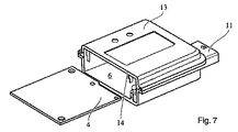
4 電子回路基板
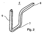
5 接触要素
6 内部の空間
7 中央の領域
8 第1の端部
9 第2の端部
10 翼形状の延長部
11 プラグ接続
12 接触凹部
13 ハウジング
14 受け入れ開口
M 組み立て方向
Claims (11)
- 電子回路基板(4)を受け入れるか又は取り囲むハウジング(13)において複数の接触要素(5)に接触する電子回路基板(4)を設置する方法であって、
前記電子回路基板(4)は、前記ハウジング(13)に受け入れられ、
前記電子回路基板(4)は、複数の接触凹部(12)を含み、
前記接触要素(5)は、前記ハウジング(13)の外側の第1の端部(8)及び前記ハウジング(13)の内側の第2の端部(9)を含み、
前記接触要素(5)のそれぞれは、前記第2の端部(9)の位置において、第1の休止位置及び第2の接触位置に位置することができる少なくとも一つの柔軟な延長部(10)を含み、
この方法は、
前記電子回路基板(4)が、前記接触要素(5)の第2の端部(9)が前記接触凹部(12)に対向するように、前記ハウジング(13)に対して位置決めされ、前記柔軟な延長部(10)が、その第1の位置に位置決めされている第1のステップと、
前記電子回路基板(4)が、一方で、前記複数の接触凹部(12)、他方で、前記接触要素(5)の第2の端部(9)の柔軟な延長部(10)によって電気的に接触され、前記柔軟な延長部(10)が、その第2の位置に位置決めされている第2のステップとを
含むことを特徴とする方法。 - 前記柔軟な延長部(10)は、少なくとも一部はその第2の方向に曲げられた請求項1に記載の方法。
- 前記柔軟な延長部(10)は、その第2の方向に、弾性的に曲げられた請求項1又は2に記載の方法。
- 前記柔軟な延長部(10)は、その第2の方向に、一部は弾性的に、一部は塑性的に曲げられた請求項1〜3のいずれかに記載の方法。
- 電子回路基板(4)と接触する接触要素(5)を有するハウジング(13)であって、前記ハウジング(13)は電子回路基板(4)を受け入れるか又は取り囲み、
前記電子回路基板(4)は、複数の接触凹部(12)を含み、
前記接触要素(5)は、前記ハウジング(13)の外側の第1の端部(8)及び前記ハウジング(13)の内側の第2の端部(9)を含み、
前記接触要素(5)のそれぞれは、その第2の端部(9)の位置において、第1の休止位置及び第2の接触位置に位置決めすることができる少なくとも一つの柔軟な延長部(10)を含み、前記電子回路基板(4)は、一方で、前記複数の接触凹部(12)によって、他方で、前記接触要素(5)の前記第2の端部(9)の前記柔軟な延長部(10)によって、電気的に接続され、前記柔軟な延長部(10)は、その第2の位置に位置決めされていることを特徴とするハウジング(13)。 - 前記柔軟な延長部(10)は、少なくとも一部はその第2の方向に曲げられた請求項5に記載のハウジング(13)。
- 前記柔軟な延長部(10)は、その第2の方向に、弾性的に曲げられた請求項5又は6に記載のハウジング(13)。
- 前記柔軟な延長部(10)は、その第2の方向に、一部は弾性的に、一部は塑性的に曲げられた請求項5〜7のいずれかに記載のハウジング(13)。
- 前記ハウジング(13)は、前記ハウジング(13)の外側に配置されたプラグ要素(11)を含む請求項5〜8のいずれかに記載のハウジング(13)。
- 前記柔軟な延長部(10)は、翼型に形成される請求項5〜9のいずれかに記載のハウジング(13)。
- 各接触要素(5)は、前記第2の端部(9)の位置において、二つの柔軟な翼型の延長部(10)を含む請求項5〜10のいずれかに記載のハウジング(13)。
Applications Claiming Priority (5)
| Application Number | Priority Date | Filing Date | Title |
|---|---|---|---|
| DE102011119576.2 | 2011-11-26 | ||
| DE102011119576 | 2011-11-26 | ||
| FR1201226A FR2983386B1 (fr) | 2011-11-26 | 2012-04-26 | Procede pour la mise en contact d'une carte imprimee electronique avec une pluralite d'elements de contacts dans un boitier recevant ou entourant la carte imprimee electronique et boitier |
| FR12/01226 | 2012-04-26 | ||
| PCT/EP2012/071635 WO2013075919A1 (fr) | 2011-11-26 | 2012-10-31 | Procede pour la mise en contact d'une carte imprimee electronique avec une pluralite d'elements de contacts dans un boitier recevant ou entourant la carte imprimee electronique et boitier |
Related Child Applications (1)
| Application Number | Title | Priority Date | Filing Date |
|---|---|---|---|
| JP2017126997A Division JP2017201631A (ja) | 2011-11-26 | 2017-06-29 | 電子回路基板を受け入れるか又は取り囲むハウジングにおいて複数の接触要素に接触する電子回路基板を設置する方法及びハウジング |
Publications (1)
| Publication Number | Publication Date |
|---|---|
| JP2014533878A true JP2014533878A (ja) | 2014-12-15 |
Family
ID=48366058
Family Applications (2)
| Application Number | Title | Priority Date | Filing Date |
|---|---|---|---|
| JP2014542752A Pending JP2014533878A (ja) | 2011-11-26 | 2012-10-31 | 電子回路基板を受け入れるか又は取り囲むハウジングにおいて複数の接触要素に接触する電子回路基板を設置する方法及びハウジング |
| JP2017126997A Pending JP2017201631A (ja) | 2011-11-26 | 2017-06-29 | 電子回路基板を受け入れるか又は取り囲むハウジングにおいて複数の接触要素に接触する電子回路基板を設置する方法及びハウジング |
Family Applications After (1)
| Application Number | Title | Priority Date | Filing Date |
|---|---|---|---|
| JP2017126997A Pending JP2017201631A (ja) | 2011-11-26 | 2017-06-29 | 電子回路基板を受け入れるか又は取り囲むハウジングにおいて複数の接触要素に接触する電子回路基板を設置する方法及びハウジング |
Country Status (6)
| Country | Link |
|---|---|
| US (1) | US9374917B2 (ja) |
| EP (1) | EP2783423B1 (ja) |
| JP (2) | JP2014533878A (ja) |
| CN (1) | CN104094473B (ja) |
| FR (1) | FR2983386B1 (ja) |
| WO (1) | WO2013075919A1 (ja) |
Families Citing this family (4)
| Publication number | Priority date | Publication date | Assignee | Title |
|---|---|---|---|---|
| DE102014213954B4 (de) * | 2014-07-17 | 2017-10-19 | Robert Bosch Gmbh | Elektronikmodul mit eingesteckter elektrischer Kontaktierung |
| DE102014213957B4 (de) * | 2014-07-17 | 2017-10-19 | Robert Bosch Gmbh | Elektronikmodul mit eingesteckter elektrischer Kontaktierung |
| CN107920431B (zh) * | 2016-10-11 | 2023-10-13 | 芋头科技(杭州)有限公司 | 一种电路板装配结构 |
| DE102019129448B3 (de) | 2019-10-31 | 2020-12-31 | Harting Electric Gmbh & Co. Kg | Gehäuse für elektronische Bauteile |
Citations (3)
| Publication number | Priority date | Publication date | Assignee | Title |
|---|---|---|---|---|
| JPH04277474A (ja) * | 1991-03-05 | 1992-10-02 | Murata Mfg Co Ltd | コネクタ端子の接続構造 |
| JPH0673876U (ja) * | 1993-03-31 | 1994-10-18 | 第一電子工業株式会社 | 角形プリント基板用コネクタ |
| JP2010501993A (ja) * | 2006-08-30 | 2010-01-21 | ローベルト ボツシユ ゲゼルシヤフト ミツト ベシユレンクテル ハフツング | 押し込みピン |
Family Cites Families (10)
| Publication number | Priority date | Publication date | Assignee | Title |
|---|---|---|---|---|
| JPH04328282A (ja) * | 1991-04-26 | 1992-11-17 | Nec Corp | 混成集積回路装置 |
| JPH0538772U (ja) * | 1991-10-25 | 1993-05-25 | 東光株式会社 | 電子部品の端子取付構造 |
| DE4324917A1 (de) * | 1992-07-27 | 1994-02-03 | Grote & Hartmann | Elektrisches Kontaktelement für eine Leiterplatten-Randverbindung |
| US5904581A (en) * | 1996-07-17 | 1999-05-18 | Minnesota Mining And Manufacturing Company | Electrical interconnection system and device |
| US5910025A (en) * | 1997-10-31 | 1999-06-08 | Ericsson, Inc. | Edge interface electrical connectors |
| JP3798177B2 (ja) * | 1999-04-06 | 2006-07-19 | 矢崎総業株式会社 | 基板用コネクタ |
| US6293833B1 (en) * | 2001-01-05 | 2001-09-25 | Yazaki North America | Low insertion force, high contact force terminal spring |
| JP2006216313A (ja) * | 2005-02-02 | 2006-08-17 | Sumitomo Wiring Syst Ltd | 端子金具 |
| DE102006025977B4 (de) * | 2006-06-02 | 2008-10-23 | Siemens Ag Österreich | Steuergerät mit einem stirnseitig kontaktierten Schaltungsträger |
| CN201238087Y (zh) * | 2008-07-04 | 2009-05-13 | 上海莫仕连接器有限公司 | 电连接器的导电端子 |
-
2012
- 2012-04-26 FR FR1201226A patent/FR2983386B1/fr not_active Expired - Fee Related
- 2012-10-31 JP JP2014542752A patent/JP2014533878A/ja active Pending
- 2012-10-31 US US14/360,569 patent/US9374917B2/en not_active Expired - Fee Related
- 2012-10-31 EP EP12783575.9A patent/EP2783423B1/fr not_active Not-in-force
- 2012-10-31 WO PCT/EP2012/071635 patent/WO2013075919A1/fr active Application Filing
- 2012-10-31 CN CN201280067477.0A patent/CN104094473B/zh not_active Expired - Fee Related
-
2017
- 2017-06-29 JP JP2017126997A patent/JP2017201631A/ja active Pending
Patent Citations (3)
| Publication number | Priority date | Publication date | Assignee | Title |
|---|---|---|---|---|
| JPH04277474A (ja) * | 1991-03-05 | 1992-10-02 | Murata Mfg Co Ltd | コネクタ端子の接続構造 |
| JPH0673876U (ja) * | 1993-03-31 | 1994-10-18 | 第一電子工業株式会社 | 角形プリント基板用コネクタ |
| JP2010501993A (ja) * | 2006-08-30 | 2010-01-21 | ローベルト ボツシユ ゲゼルシヤフト ミツト ベシユレンクテル ハフツング | 押し込みピン |
Also Published As
| Publication number | Publication date |
|---|---|
| FR2983386B1 (fr) | 2015-06-12 |
| CN104094473B (zh) | 2017-02-22 |
| EP2783423B1 (fr) | 2018-12-05 |
| WO2013075919A1 (fr) | 2013-05-30 |
| FR2983386A1 (fr) | 2013-05-31 |
| US20140321082A1 (en) | 2014-10-30 |
| JP2017201631A (ja) | 2017-11-09 |
| EP2783423A1 (fr) | 2014-10-01 |
| US9374917B2 (en) | 2016-06-21 |
| CN104094473A (zh) | 2014-10-08 |
Similar Documents
| Publication | Publication Date | Title |
|---|---|---|
| US9634407B2 (en) | Terminal module | |
| JP5517180B2 (ja) | プラグコネクタソケット用のコンタクトスプリング | |
| JP2017201631A (ja) | 電子回路基板を受け入れるか又は取り囲むハウジングにおいて複数の接触要素に接触する電子回路基板を設置する方法及びハウジング | |
| JP6269451B2 (ja) | 電気接続構造 | |
| JP2008010656A (ja) | 半導体装置 | |
| EP3598583B1 (en) | Electronic device having fixed electric conductive plate and flexible electric conductive plate | |
| JP4851243B2 (ja) | コンデンサ内蔵ジョイントコネクタ | |
| JP4820241B2 (ja) | 配線基板収納構造 | |
| CN104518300B (zh) | 电子电路装置 | |
| KR101702548B1 (ko) | 스위치 장치 | |
| CN108574151B (zh) | 将电气部件安装在印刷电路板上的安装辅助件及安装方法 | |
| CN104682039B (zh) | 引导装置 | |
| JP7094087B2 (ja) | 電池装置 | |
| JP2020512686A (ja) | 電子モジュール及び電子モジュールの製造方法 | |
| JP2013084476A5 (ja) | ||
| KR20170029684A (ko) | Pcb 기판의 안착홀에 삽입되는 스프링이 구비된 pcb 조립체 | |
| JP2010230329A (ja) | 基板固定構造および物理量センサ | |
| JP5931095B2 (ja) | 2つのばね領域を備えた直接差込エレメント | |
| KR20150095371A (ko) | 표면 실장형 이중 접속단자 | |
| CN104779475B (zh) | 卡连接器 | |
| JP3186949U (ja) | 電気コネクタ | |
| JP6954774B2 (ja) | 制御ユニット | |
| KR102542322B1 (ko) | 전자 부품 | |
| JP2003051652A (ja) | 配線ユニット | |
| JP2015204311A (ja) | 電子装置 |
Legal Events
| Date | Code | Title | Description |
|---|---|---|---|
| A621 | Written request for application examination |
Free format text: JAPANESE INTERMEDIATE CODE: A621 Effective date: 20151019 |
|
| A977 | Report on retrieval |
Free format text: JAPANESE INTERMEDIATE CODE: A971007 Effective date: 20160812 |
|
| A131 | Notification of reasons for refusal |
Free format text: JAPANESE INTERMEDIATE CODE: A131 Effective date: 20160816 |
|
| A601 | Written request for extension of time |
Free format text: JAPANESE INTERMEDIATE CODE: A601 Effective date: 20161115 |
|
| A521 | Request for written amendment filed |
Free format text: JAPANESE INTERMEDIATE CODE: A523 Effective date: 20170210 |
|
| A02 | Decision of refusal |
Free format text: JAPANESE INTERMEDIATE CODE: A02 Effective date: 20170228 |


