JP2010141204A - 配線基板及びその製造方法 - Google Patents
配線基板及びその製造方法 Download PDFInfo
- Publication number
- JP2010141204A JP2010141204A JP2008317410A JP2008317410A JP2010141204A JP 2010141204 A JP2010141204 A JP 2010141204A JP 2008317410 A JP2008317410 A JP 2008317410A JP 2008317410 A JP2008317410 A JP 2008317410A JP 2010141204 A JP2010141204 A JP 2010141204A
- Authority
- JP
- Japan
- Prior art keywords
- layer
- pad
- forming
- cavity
- insulating layer
- Prior art date
- Legal status (The legal status is an assumption and is not a legal conclusion. Google has not performed a legal analysis and makes no representation as to the accuracy of the status listed.)
- Granted
Links
Images

Classifications
-
- H—ELECTRICITY
- H10—SEMICONDUCTOR DEVICES; ELECTRIC SOLID-STATE DEVICES NOT OTHERWISE PROVIDED FOR
- H10W—GENERIC PACKAGES, INTERCONNECTIONS, CONNECTORS OR OTHER CONSTRUCTIONAL DETAILS OF DEVICES COVERED BY CLASS H10
- H10W70/00—Package substrates; Interposers; Redistribution layers [RDL]
- H10W70/60—Insulating or insulated package substrates; Interposers; Redistribution layers
- H10W70/67—Insulating or insulated package substrates; Interposers; Redistribution layers characterised by their insulating layers or insulating parts
- H10W70/68—Shapes or dispositions thereof
-
- H—ELECTRICITY
- H05—ELECTRIC TECHNIQUES NOT OTHERWISE PROVIDED FOR
- H05K—PRINTED CIRCUITS; CASINGS OR CONSTRUCTIONAL DETAILS OF ELECTRIC APPARATUS; MANUFACTURE OF ASSEMBLAGES OF ELECTRICAL COMPONENTS
- H05K3/00—Apparatus or processes for manufacturing printed circuits
- H05K3/46—Manufacturing multilayer circuits
- H05K3/4697—Manufacturing multilayer circuits having cavities, e.g. for mounting components
-
- H—ELECTRICITY
- H10—SEMICONDUCTOR DEVICES; ELECTRIC SOLID-STATE DEVICES NOT OTHERWISE PROVIDED FOR
- H10W—GENERIC PACKAGES, INTERCONNECTIONS, CONNECTORS OR OTHER CONSTRUCTIONAL DETAILS OF DEVICES COVERED BY CLASS H10
- H10W70/00—Package substrates; Interposers; Redistribution layers [RDL]
- H10W70/60—Insulating or insulated package substrates; Interposers; Redistribution layers
- H10W70/67—Insulating or insulated package substrates; Interposers; Redistribution layers characterised by their insulating layers or insulating parts
- H10W70/68—Shapes or dispositions thereof
- H10W70/685—Shapes or dispositions thereof comprising multiple insulating layers
-
- H—ELECTRICITY
- H10—SEMICONDUCTOR DEVICES; ELECTRIC SOLID-STATE DEVICES NOT OTHERWISE PROVIDED FOR
- H10W—GENERIC PACKAGES, INTERCONNECTIONS, CONNECTORS OR OTHER CONSTRUCTIONAL DETAILS OF DEVICES COVERED BY CLASS H10
- H10W90/00—Package configurations
-
- H—ELECTRICITY
- H05—ELECTRIC TECHNIQUES NOT OTHERWISE PROVIDED FOR
- H05K—PRINTED CIRCUITS; CASINGS OR CONSTRUCTIONAL DETAILS OF ELECTRIC APPARATUS; MANUFACTURE OF ASSEMBLAGES OF ELECTRICAL COMPONENTS
- H05K1/00—Printed circuits
- H05K1/18—Printed circuits structurally associated with non-printed electric components
- H05K1/182—Printed circuits structurally associated with non-printed electric components associated with components mounted in printed circuit boards [PCB], e.g. insert-mounted components [IMC]
- H05K1/183—Printed circuits structurally associated with non-printed electric components associated with components mounted in printed circuit boards [PCB], e.g. insert-mounted components [IMC] associated with components mounted in and supported by recessed areas of the PCBs
-
- H—ELECTRICITY
- H05—ELECTRIC TECHNIQUES NOT OTHERWISE PROVIDED FOR
- H05K—PRINTED CIRCUITS; CASINGS OR CONSTRUCTIONAL DETAILS OF ELECTRIC APPARATUS; MANUFACTURE OF ASSEMBLAGES OF ELECTRICAL COMPONENTS
- H05K2201/00—Indexing scheme relating to printed circuits covered by H05K1/00
- H05K2201/09—Shape and layout
- H05K2201/09209—Shape and layout details of conductors
- H05K2201/09372—Pads and lands
- H05K2201/09472—Recessed pad for surface mounting; Recessed electrode of component
-
- H—ELECTRICITY
- H05—ELECTRIC TECHNIQUES NOT OTHERWISE PROVIDED FOR
- H05K—PRINTED CIRCUITS; CASINGS OR CONSTRUCTIONAL DETAILS OF ELECTRIC APPARATUS; MANUFACTURE OF ASSEMBLAGES OF ELECTRICAL COMPONENTS
- H05K2201/00—Indexing scheme relating to printed circuits covered by H05K1/00
- H05K2201/09—Shape and layout
- H05K2201/09209—Shape and layout details of conductors
- H05K2201/09372—Pads and lands
- H05K2201/09481—Via in pad; Pad over filled via
-
- H—ELECTRICITY
- H05—ELECTRIC TECHNIQUES NOT OTHERWISE PROVIDED FOR
- H05K—PRINTED CIRCUITS; CASINGS OR CONSTRUCTIONAL DETAILS OF ELECTRIC APPARATUS; MANUFACTURE OF ASSEMBLAGES OF ELECTRICAL COMPONENTS
- H05K2201/00—Indexing scheme relating to printed circuits covered by H05K1/00
- H05K2201/10—Details of components or other objects attached to or integrated in a printed circuit board
- H05K2201/10613—Details of electrical connections of non-printed components, e.g. special leads
- H05K2201/10621—Components characterised by their electrical contacts
- H05K2201/10674—Flip chip
-
- H—ELECTRICITY
- H05—ELECTRIC TECHNIQUES NOT OTHERWISE PROVIDED FOR
- H05K—PRINTED CIRCUITS; CASINGS OR CONSTRUCTIONAL DETAILS OF ELECTRIC APPARATUS; MANUFACTURE OF ASSEMBLAGES OF ELECTRICAL COMPONENTS
- H05K2203/00—Indexing scheme relating to apparatus or processes for manufacturing printed circuits covered by H05K3/00
- H05K2203/03—Metal processing
- H05K2203/0369—Etching selective parts of a metal substrate through part of its thickness, e.g. using etch resist
-
- H—ELECTRICITY
- H05—ELECTRIC TECHNIQUES NOT OTHERWISE PROVIDED FOR
- H05K—PRINTED CIRCUITS; CASINGS OR CONSTRUCTIONAL DETAILS OF ELECTRIC APPARATUS; MANUFACTURE OF ASSEMBLAGES OF ELECTRICAL COMPONENTS
- H05K2203/00—Indexing scheme relating to apparatus or processes for manufacturing printed circuits covered by H05K3/00
- H05K2203/03—Metal processing
- H05K2203/0376—Etching temporary metallic carrier substrate
-
- H—ELECTRICITY
- H05—ELECTRIC TECHNIQUES NOT OTHERWISE PROVIDED FOR
- H05K—PRINTED CIRCUITS; CASINGS OR CONSTRUCTIONAL DETAILS OF ELECTRIC APPARATUS; MANUFACTURE OF ASSEMBLAGES OF ELECTRICAL COMPONENTS
- H05K3/00—Apparatus or processes for manufacturing printed circuits
- H05K3/10—Apparatus or processes for manufacturing printed circuits in which conductive material is applied to the insulating support in such a manner as to form the desired conductive pattern
- H05K3/20—Apparatus or processes for manufacturing printed circuits in which conductive material is applied to the insulating support in such a manner as to form the desired conductive pattern by affixing prefabricated conductor pattern
- H05K3/205—Apparatus or processes for manufacturing printed circuits in which conductive material is applied to the insulating support in such a manner as to form the desired conductive pattern by affixing prefabricated conductor pattern using a pattern electroplated or electroformed on a metallic carrier
-
- H—ELECTRICITY
- H05—ELECTRIC TECHNIQUES NOT OTHERWISE PROVIDED FOR
- H05K—PRINTED CIRCUITS; CASINGS OR CONSTRUCTIONAL DETAILS OF ELECTRIC APPARATUS; MANUFACTURE OF ASSEMBLAGES OF ELECTRICAL COMPONENTS
- H05K3/00—Apparatus or processes for manufacturing printed circuits
- H05K3/46—Manufacturing multilayer circuits
- H05K3/4644—Manufacturing multilayer circuits by building the multilayer layer by layer, i.e. build-up multilayer circuits
- H05K3/4682—Manufacture of core-less build-up multilayer circuits on a temporary carrier or on a metal foil
-
- H—ELECTRICITY
- H10—SEMICONDUCTOR DEVICES; ELECTRIC SOLID-STATE DEVICES NOT OTHERWISE PROVIDED FOR
- H10W—GENERIC PACKAGES, INTERCONNECTIONS, CONNECTORS OR OTHER CONSTRUCTIONAL DETAILS OF DEVICES COVERED BY CLASS H10
- H10W70/00—Package substrates; Interposers; Redistribution layers [RDL]
- H10W70/60—Insulating or insulated package substrates; Interposers; Redistribution layers
- H10W70/62—Insulating or insulated package substrates; Interposers; Redistribution layers characterised by their interconnections
- H10W70/63—Vias, e.g. via plugs
- H10W70/635—Through-vias
-
- H—ELECTRICITY
- H10—SEMICONDUCTOR DEVICES; ELECTRIC SOLID-STATE DEVICES NOT OTHERWISE PROVIDED FOR
- H10W—GENERIC PACKAGES, INTERCONNECTIONS, CONNECTORS OR OTHER CONSTRUCTIONAL DETAILS OF DEVICES COVERED BY CLASS H10
- H10W72/00—Interconnections or connectors in packages
-
- H—ELECTRICITY
- H10—SEMICONDUCTOR DEVICES; ELECTRIC SOLID-STATE DEVICES NOT OTHERWISE PROVIDED FOR
- H10W—GENERIC PACKAGES, INTERCONNECTIONS, CONNECTORS OR OTHER CONSTRUCTIONAL DETAILS OF DEVICES COVERED BY CLASS H10
- H10W74/00—Encapsulations, e.g. protective coatings
- H10W74/10—Encapsulations, e.g. protective coatings characterised by their shape or disposition
- H10W74/15—Encapsulations, e.g. protective coatings characterised by their shape or disposition on active surfaces of flip-chip devices, e.g. underfills
-
- H—ELECTRICITY
- H10—SEMICONDUCTOR DEVICES; ELECTRIC SOLID-STATE DEVICES NOT OTHERWISE PROVIDED FOR
- H10W—GENERIC PACKAGES, INTERCONNECTIONS, CONNECTORS OR OTHER CONSTRUCTIONAL DETAILS OF DEVICES COVERED BY CLASS H10
- H10W90/00—Package configurations
- H10W90/701—Package configurations characterised by the relative positions of pads or connectors relative to package parts
- H10W90/721—Package configurations characterised by the relative positions of pads or connectors relative to package parts of bump connectors
- H10W90/722—Package configurations characterised by the relative positions of pads or connectors relative to package parts of bump connectors between stacked chips
-
- H—ELECTRICITY
- H10—SEMICONDUCTOR DEVICES; ELECTRIC SOLID-STATE DEVICES NOT OTHERWISE PROVIDED FOR
- H10W—GENERIC PACKAGES, INTERCONNECTIONS, CONNECTORS OR OTHER CONSTRUCTIONAL DETAILS OF DEVICES COVERED BY CLASS H10
- H10W90/00—Package configurations
- H10W90/701—Package configurations characterised by the relative positions of pads or connectors relative to package parts
- H10W90/721—Package configurations characterised by the relative positions of pads or connectors relative to package parts of bump connectors
- H10W90/724—Package configurations characterised by the relative positions of pads or connectors relative to package parts of bump connectors between a chip and a stacked insulating package substrate, interposer or RDL
-
- H—ELECTRICITY
- H10—SEMICONDUCTOR DEVICES; ELECTRIC SOLID-STATE DEVICES NOT OTHERWISE PROVIDED FOR
- H10W—GENERIC PACKAGES, INTERCONNECTIONS, CONNECTORS OR OTHER CONSTRUCTIONAL DETAILS OF DEVICES COVERED BY CLASS H10
- H10W90/00—Package configurations
- H10W90/701—Package configurations characterised by the relative positions of pads or connectors relative to package parts
- H10W90/731—Package configurations characterised by the relative positions of pads or connectors relative to package parts of die-attach connectors
- H10W90/734—Package configurations characterised by the relative positions of pads or connectors relative to package parts of die-attach connectors between a chip and a stacked insulating package substrate, interposer or RDL
-
- Y—GENERAL TAGGING OF NEW TECHNOLOGICAL DEVELOPMENTS; GENERAL TAGGING OF CROSS-SECTIONAL TECHNOLOGIES SPANNING OVER SEVERAL SECTIONS OF THE IPC; TECHNICAL SUBJECTS COVERED BY FORMER USPC CROSS-REFERENCE ART COLLECTIONS [XRACs] AND DIGESTS
- Y10—TECHNICAL SUBJECTS COVERED BY FORMER USPC
- Y10T—TECHNICAL SUBJECTS COVERED BY FORMER US CLASSIFICATION
- Y10T156/00—Adhesive bonding and miscellaneous chemical manufacture
- Y10T156/10—Methods of surface bonding and/or assembly therefor
Landscapes
- Engineering & Computer Science (AREA)
- Manufacturing & Machinery (AREA)
- Microelectronics & Electronic Packaging (AREA)
- Production Of Multi-Layered Print Wiring Board (AREA)
Abstract
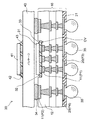
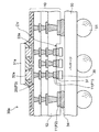
【解決手段】配線基板(パッケージ)10は、その一方の面側の最外層の絶縁層12の、チップ搭載エリアに対応する箇所にキャビティCVが形成され、このキャビティCV内の絶縁層12の表面に露出するパッドP1と、キャビティCVの周囲の絶縁層12の表面に露出するパッドP2とを備えている。そして、このパッケージ10のキャビティCV内のパッドP1にチップ31がフリップチップ接続され、キャビティCVの周囲のパッドP2に他のパッケージ40が接続されて、POP構造の半導体装置30を構成している。
【選択図】図5
Description
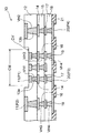
図1は本発明の第1の実施形態に係る配線基板(半導体パッケージ)の構成を断面図の形態で示したものである。
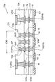
図7は本発明の第2の実施形態に係る配線基板(半導体パッケージ)の構成を断面図の形態で示したものである。
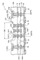
図8は本発明の第3の実施形態に係る配線基板(半導体パッケージ)の構成を断面図の形態で示したものである。
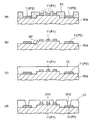
上述した各実施形態では、パッケージ10(10a,10b)に電子部品(チップ)を収容するためのキャビティCVを、所要の形状にパターニングされたエッチングレジスト61(図2(c))をマスクにしてエッチングを施すことで形成した場合を例にとって説明したが、キャビティCVを形成する方法がこれに限定されないことはもちろんである。例えば、図2(b)の工程において、支持基材60上に形成すべきレジスト層を、図示のパターンとは逆のパターン(ポジとネガの関係)としためっきレジストとし、このめっきレジストを利用して所要のキャビティCVを形成することも可能である。
11,14,17,20…配線層、
12,12a,12b,15,18…樹脂層(絶縁層)、
13a,13b,16,19…ビア、
21…ソルダレジスト層(絶縁層)、
30,30a…半導体装置、
31,31a,36,41…半導体素子(チップ/電子部品)、
32,32a,34,37,42…はんだ(バンプ)、
33,33a,43…アンダーフィル樹脂、
60,60a…支持基材、
61,62…レジスト層、
CM…チップ搭載エリア、
CV…キャビティ、
DP,DP1,DP2…凹部、
P1,P2,P3,P4…パッド、
VH1,VH2,VH3,VH4…ビアホール。
Claims (5)
- 支持基材上に、形成すべきキャビティの位置に対応する部分のみが残存するようパターン形成された第1のレジスト層を形成する工程と、
前記第1のレジスト層をマスクにして前記支持基材を所要量だけ除去し、段差部を有した支持基材を形成する工程と、
前記第1のレジスト層を除去後、前記支持基材の段差部が形成されている側の面に、該段差部の上の部分及び下の部分に対応する箇所にそれぞれ第1の開口部及び第2の開口部を有するようパターン形成された第2のレジスト層を形成する工程と、
前記第2のレジスト層の第1、第2の各開口部から露出している前記支持基材上に、それぞれ第1のパッド及び第2のパッドを形成する工程と、
前記第2のレジスト層を除去後、前記支持基材上に、前記第1、第2の各パッドを覆う絶縁層を形成する工程と、
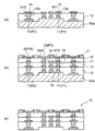
前記絶縁層の上面から前記各パッドの一部を露出させる開口を形成する工程と、
前記絶縁層上に、前記各パッドにそれぞれ接続されるビアを含む配線層を形成する工程と、
以降、所要の層数となるまで絶縁層と配線層を交互に積層した後、前記支持基材を除去する工程とを含むことを特徴とする配線基板の製造方法。 - 前記第1のパッド及び第2のパッドを形成する工程の前に、前記第2のレジスト層から露出する第1の開口部及び第2の開口部の少なくとも一方に、犠牲導体層を形成する工程を含むことを特徴とする請求項1に記載の配線基板の製造方法。
- 支持基材上に、形成すべきキャビティの位置に対応する箇所に開口部を有するようパターン形成された第1のレジスト層を形成する工程と、
前記第1のレジスト層の開口部から露出している前記支持基材上に、犠牲導体層を所要の厚さに形成して、段差部を有した支持基材を形成する工程と、
前記第1のレジスト層を除去後、前記支持基材の段差部が形成されている側の面に、該段差部の上の部分の犠牲導体層上及び該段差部の下の部分に対応する箇所にそれぞれ第1の開口部及び第2の開口部を有するようパターン形成された第2のレジスト層を形成する工程と、
前記第2のレジスト層の第1、第2の各開口部から露出している前記犠牲導体層及び前記支持基材上に、それぞれ第1のパッド及び第2のパッドを形成する工程と、
前記第2のレジスト層を除去後、前記犠牲導体層及び前記支持基材上に、前記第1、第2の各パッドを露出させて絶縁層を形成する工程と、
前記絶縁層の上面から前記各パッドの一部を露出させる開口を形成する工程と、
前記絶縁層上に、前記各パッドにそれぞれ接続されるビアを含む配線層を形成する工程と、
以降、所要の層数となるまで絶縁層と配線層を交互に積層した後、前記支持基材及び前記犠牲導体層を除去する工程とを含むことを特徴とする配線基板の製造方法。 - 一方の面側の最外層の絶縁層の、電子部品の搭載エリアに対応する箇所にキャビティが形成され、
前記キャビティ内の前記絶縁層の表面に露出する第1のパッドと、
前記キャビティの周囲の前記絶縁層の表面に露出する第2のパッドとを備えたことを特徴とする配線基板。 - 前記キャビティ内の前記絶縁層の表面に露出する第1のパッドに代えて、前記キャビティ内の前記絶縁層の表面から基板内側に後退した位置に露出する第1のパッドを備えたことを特徴とする請求項4に記載の配線基板。
Priority Applications (2)
| Application Number | Priority Date | Filing Date | Title |
|---|---|---|---|
| JP2008317410A JP5026400B2 (ja) | 2008-12-12 | 2008-12-12 | 配線基板及びその製造方法 |
| US12/628,281 US8067695B2 (en) | 2008-12-12 | 2009-12-01 | Wiring board and method of manufacturing the same |
Applications Claiming Priority (1)
| Application Number | Priority Date | Filing Date | Title |
|---|---|---|---|
| JP2008317410A JP5026400B2 (ja) | 2008-12-12 | 2008-12-12 | 配線基板及びその製造方法 |
Publications (3)
| Publication Number | Publication Date |
|---|---|
| JP2010141204A true JP2010141204A (ja) | 2010-06-24 |
| JP2010141204A5 JP2010141204A5 (ja) | 2011-10-27 |
| JP5026400B2 JP5026400B2 (ja) | 2012-09-12 |
Family
ID=42239171
Family Applications (1)
| Application Number | Title | Priority Date | Filing Date |
|---|---|---|---|
| JP2008317410A Active JP5026400B2 (ja) | 2008-12-12 | 2008-12-12 | 配線基板及びその製造方法 |
Country Status (2)
| Country | Link |
|---|---|
| US (1) | US8067695B2 (ja) |
| JP (1) | JP5026400B2 (ja) |
Cited By (6)
| Publication number | Priority date | Publication date | Assignee | Title |
|---|---|---|---|---|
| JP2012195447A (ja) * | 2011-03-16 | 2012-10-11 | Shinko Electric Ind Co Ltd | 配線基板及びその製造方法 |
| JP2013115290A (ja) * | 2011-11-30 | 2013-06-10 | Fujitsu Semiconductor Ltd | 半導体装置及び半導体装置の製造方法 |
| JP2015165533A (ja) * | 2014-03-03 | 2015-09-17 | 新光電気工業株式会社 | 配線基板及びその製造方法と半導体装置 |
| US11382213B2 (en) | 2020-10-30 | 2022-07-05 | Samsung Electro-Mechanics Co., Ltd. | Printed circuit board |
| JP2023539243A (ja) * | 2020-08-24 | 2023-09-13 | テキサス インスツルメンツ インコーポレイテッド | 半導体パッケージキャビティ内の電子デバイス |
| US12575027B2 (en) | 2023-09-01 | 2026-03-10 | Samsung Electro-Mechanics Co., Ltd. | Printed circuit board |
Families Citing this family (38)
| Publication number | Priority date | Publication date | Assignee | Title |
|---|---|---|---|---|
| KR101019161B1 (ko) * | 2008-12-11 | 2011-03-04 | 삼성전기주식회사 | 패키지 기판 |
| JP5290215B2 (ja) * | 2010-02-15 | 2013-09-18 | ルネサスエレクトロニクス株式会社 | 半導体装置、半導体パッケージ、インタポーザ、及びインタポーザの製造方法 |
| US20120152606A1 (en) * | 2010-12-16 | 2012-06-21 | Ibiden Co., Ltd. | Printed wiring board |
| US8466559B2 (en) | 2010-12-17 | 2013-06-18 | Intel Corporation | Forming die backside coating structures with coreless packages |
| CN102548253B (zh) * | 2010-12-28 | 2013-11-06 | 富葵精密组件(深圳)有限公司 | 多层电路板的制作方法 |
| JP2014072372A (ja) * | 2012-09-28 | 2014-04-21 | Ibiden Co Ltd | プリント配線板の製造方法及びプリント配線板 |
| US9275925B2 (en) | 2013-03-12 | 2016-03-01 | Taiwan Semiconductor Manufacturing Company, Ltd. | System and method for an improved interconnect structure |
| US9263376B2 (en) * | 2013-04-15 | 2016-02-16 | Intel Deutschland Gmbh | Chip interposer, semiconductor device, and method for manufacturing a semiconductor device |
| TW201503777A (zh) * | 2013-05-30 | 2015-01-16 | 京瓷Slc技術股份有限公司 | 配線基板 |
| JP2015035496A (ja) * | 2013-08-09 | 2015-02-19 | イビデン株式会社 | 電子部品内蔵配線板の製造方法 |
| KR20150021342A (ko) * | 2013-08-20 | 2015-03-02 | 삼성전기주식회사 | 다층인쇄회로기판 |
| US9159670B2 (en) | 2013-08-29 | 2015-10-13 | Qualcomm Incorporated | Ultra fine pitch and spacing interconnects for substrate |
| US9622350B2 (en) * | 2013-09-28 | 2017-04-11 | Intel Corporation | Method of forming a circuit board |
| TWI666749B (zh) * | 2014-02-19 | 2019-07-21 | Siliconware Precision Industries Co., Ltd. | 封裝基板及封裝結構 |
| TW201539596A (zh) * | 2014-04-09 | 2015-10-16 | 同欣電子工業股份有限公司 | 中介體及其製造方法 |
| US9609751B2 (en) * | 2014-04-11 | 2017-03-28 | Qualcomm Incorporated | Package substrate comprising surface interconnect and cavity comprising electroless fill |
| TWI504320B (zh) * | 2014-06-17 | 2015-10-11 | 矽品精密工業股份有限公司 | 線路結構及其製法 |
| TWI611523B (zh) * | 2014-09-05 | 2018-01-11 | 矽品精密工業股份有限公司 | 半導體封裝件之製法 |
| TWI551207B (zh) * | 2014-09-12 | 2016-09-21 | 矽品精密工業股份有限公司 | 基板結構及其製法 |
| US20160093567A1 (en) * | 2014-09-26 | 2016-03-31 | Qualcomm Incorporated | System, apparatus, and method of interconnection in a substrate |
| JP2016162835A (ja) * | 2015-02-27 | 2016-09-05 | イビデン株式会社 | 多層配線板 |
| KR102340053B1 (ko) * | 2015-06-18 | 2021-12-16 | 삼성전기주식회사 | 인쇄회로기판 및 인쇄회로기판의 제조 방법 |
| CN104966709B (zh) | 2015-07-29 | 2017-11-03 | 恒劲科技股份有限公司 | 封装基板及其制作方法 |
| JP2017084997A (ja) * | 2015-10-29 | 2017-05-18 | イビデン株式会社 | プリント配線板及びその製造方法 |
| CN107424973B (zh) * | 2016-05-23 | 2020-01-21 | 凤凰先驱股份有限公司 | 封装基板及其制法 |
| WO2018004686A1 (en) * | 2016-07-01 | 2018-01-04 | Intel Corporation | Device, method and system for providing recessed interconnect structures of a substrate |
| US11272619B2 (en) * | 2016-09-02 | 2022-03-08 | Intel Corporation | Apparatus with embedded fine line space in a cavity, and a method for forming the same |
| TWI595812B (zh) * | 2016-11-30 | 2017-08-11 | 欣興電子股份有限公司 | 線路板結構及其製作方法 |
| US9997442B1 (en) * | 2016-12-14 | 2018-06-12 | Advanced Semiconductor Engineering, Inc. | Semiconductor device and method of manufacturing the same |
| JP6789886B2 (ja) * | 2017-06-09 | 2020-11-25 | 株式会社東芝 | 電子装置 |
| CN109803481B (zh) * | 2017-11-17 | 2021-07-06 | 英业达科技有限公司 | 多层印刷电路板及制作多层印刷电路板的方法 |
| EP3849286B1 (en) * | 2020-01-09 | 2025-08-27 | Murata Manufacturing Co., Ltd. | Electronic device with differential transmission lines equipped with 3d capacitors supported by a base, and corresponding manufacturing method |
| KR102876502B1 (ko) | 2020-07-09 | 2025-10-23 | 삼성전자주식회사 | 인터포저를 포함하는 반도체 패키지 및 반도체 패키지의 제조 방법 |
| US20220069489A1 (en) * | 2020-08-28 | 2022-03-03 | Unimicron Technology Corp. | Circuit board structure and manufacturing method thereof |
| KR102921311B1 (ko) * | 2020-12-01 | 2026-02-02 | 삼성전자주식회사 | 지지 부재를 갖는 반도체 패키지 |
| JP7711870B2 (ja) * | 2021-10-19 | 2025-07-23 | 新光電気工業株式会社 | 配線基板及びその製造方法 |
| TWI803312B (zh) * | 2021-12-23 | 2023-05-21 | 南亞科技股份有限公司 | 具有多堆疊載體結構之半導體元件 |
| JP2023125724A (ja) | 2022-02-28 | 2023-09-07 | 新光電気工業株式会社 | 配線基板及びその製造方法 |
Family Cites Families (5)
| Publication number | Priority date | Publication date | Assignee | Title |
|---|---|---|---|---|
| US6281446B1 (en) * | 1998-02-16 | 2001-08-28 | Matsushita Electric Industrial Co., Ltd. | Multi-layered circuit board and method of manufacturing the same |
| EP1990833A3 (en) * | 2000-02-25 | 2010-09-29 | Ibiden Co., Ltd. | Multilayer printed circuit board and multilayer printed circuit board manufacturing method |
| JP3709882B2 (ja) * | 2003-07-22 | 2005-10-26 | 松下電器産業株式会社 | 回路モジュールとその製造方法 |
| KR100792352B1 (ko) | 2006-07-06 | 2008-01-08 | 삼성전기주식회사 | 패키지 온 패키지의 바텀기판 및 그 제조방법 |
| TWI335643B (en) * | 2006-11-21 | 2011-01-01 | Unimicron Technology Crop | Circuit board structure having embedded semiconductor chip and fabrication method thereof |
-
2008
- 2008-12-12 JP JP2008317410A patent/JP5026400B2/ja active Active
-
2009
- 2009-12-01 US US12/628,281 patent/US8067695B2/en active Active
Cited By (7)
| Publication number | Priority date | Publication date | Assignee | Title |
|---|---|---|---|---|
| JP2012195447A (ja) * | 2011-03-16 | 2012-10-11 | Shinko Electric Ind Co Ltd | 配線基板及びその製造方法 |
| US9078384B2 (en) | 2011-03-16 | 2015-07-07 | Shinko Electric Industries Co., Ltd. | Wiring substrate and method of manufacturing the same |
| JP2013115290A (ja) * | 2011-11-30 | 2013-06-10 | Fujitsu Semiconductor Ltd | 半導体装置及び半導体装置の製造方法 |
| JP2015165533A (ja) * | 2014-03-03 | 2015-09-17 | 新光電気工業株式会社 | 配線基板及びその製造方法と半導体装置 |
| JP2023539243A (ja) * | 2020-08-24 | 2023-09-13 | テキサス インスツルメンツ インコーポレイテッド | 半導体パッケージキャビティ内の電子デバイス |
| US11382213B2 (en) | 2020-10-30 | 2022-07-05 | Samsung Electro-Mechanics Co., Ltd. | Printed circuit board |
| US12575027B2 (en) | 2023-09-01 | 2026-03-10 | Samsung Electro-Mechanics Co., Ltd. | Printed circuit board |
Also Published As
| Publication number | Publication date |
|---|---|
| JP5026400B2 (ja) | 2012-09-12 |
| US20100147560A1 (en) | 2010-06-17 |
| US8067695B2 (en) | 2011-11-29 |
Similar Documents
| Publication | Publication Date | Title |
|---|---|---|
| JP5026400B2 (ja) | 配線基板及びその製造方法 | |
| JP5221315B2 (ja) | 配線基板及びその製造方法 | |
| JP5210839B2 (ja) | 配線基板及びその製造方法 | |
| JP5711472B2 (ja) | 配線基板及びその製造方法並びに半導体装置 | |
| JP5147779B2 (ja) | 配線基板の製造方法及び半導体パッケージの製造方法 | |
| JP3813402B2 (ja) | 半導体装置の製造方法 | |
| JP5649490B2 (ja) | 配線基板及びその製造方法 | |
| JP6076653B2 (ja) | 電子部品内蔵基板及び電子部品内蔵基板の製造方法 | |
| JP5339928B2 (ja) | 配線基板及びその製造方法 | |
| KR102331611B1 (ko) | 전자 부품 장치 및 그 제조 방법 | |
| JP4619223B2 (ja) | 半導体パッケージ及びその製造方法 | |
| US9935053B2 (en) | Electronic component integrated substrate | |
| JP2005217225A (ja) | 半導体装置及びその製造方法 | |
| JP2010245280A (ja) | 配線基板の製造方法及び配線基板 | |
| JP2005209689A (ja) | 半導体装置及びその製造方法 | |
| JP2009135162A (ja) | 配線基板及び電子部品装置 | |
| JP2008282842A (ja) | 配線基板及びその製造方法 | |
| JP6550260B2 (ja) | 配線基板及び配線基板の製造方法 | |
| JP2017163027A (ja) | 配線基板、半導体装置及び配線基板の製造方法 | |
| JP2012235166A (ja) | 配線基板及びその製造方法 | |
| KR20190136240A (ko) | 패키지 기판 및 그 제조방법 | |
| JP5315447B2 (ja) | 配線基板及びその製造方法 | |
| JP2006049762A (ja) | 部品内蔵基板及び部品内蔵基板の製造方法 | |
| JP2010067888A (ja) | 配線基板及びその製造方法 | |
| JP3800215B2 (ja) | 印刷配線板、半導体装置、及びそれらの製造方法 |
Legal Events
| Date | Code | Title | Description |
|---|---|---|---|
| A521 | Request for written amendment filed |
Free format text: JAPANESE INTERMEDIATE CODE: A523 Effective date: 20110908 |
|
| A621 | Written request for application examination |
Free format text: JAPANESE INTERMEDIATE CODE: A621 Effective date: 20110908 |
|
| A977 | Report on retrieval |
Free format text: JAPANESE INTERMEDIATE CODE: A971007 Effective date: 20120524 |
|
| TRDD | Decision of grant or rejection written | ||
| A01 | Written decision to grant a patent or to grant a registration (utility model) |
Free format text: JAPANESE INTERMEDIATE CODE: A01 Effective date: 20120619 |
|
| A01 | Written decision to grant a patent or to grant a registration (utility model) |
Free format text: JAPANESE INTERMEDIATE CODE: A01 |
|
| A61 | First payment of annual fees (during grant procedure) |
Free format text: JAPANESE INTERMEDIATE CODE: A61 Effective date: 20120620 |
|
| FPAY | Renewal fee payment (event date is renewal date of database) |
Free format text: PAYMENT UNTIL: 20150629 Year of fee payment: 3 |
|
| R150 | Certificate of patent or registration of utility model |
Ref document number: 5026400 Country of ref document: JP Free format text: JAPANESE INTERMEDIATE CODE: R150 Free format text: JAPANESE INTERMEDIATE CODE: R150 |