EP4375202A1 - Automatische bündelwerkzeugvorrichtung mit führungseinheit für deformierte und/oder lose einstückige bänder - Google Patents
Automatische bündelwerkzeugvorrichtung mit führungseinheit für deformierte und/oder lose einstückige bänder Download PDFInfo
- Publication number
- EP4375202A1 EP4375202A1 EP23201566.9A EP23201566A EP4375202A1 EP 4375202 A1 EP4375202 A1 EP 4375202A1 EP 23201566 A EP23201566 A EP 23201566A EP 4375202 A1 EP4375202 A1 EP 4375202A1
- Authority
- EP
- European Patent Office
- Prior art keywords
- opt
- guiding
- bundling
- unit
- abt
- Prior art date
- Legal status (The legal status is an assumption and is not a legal conclusion. Google has not performed a legal analysis and makes no representation as to the accuracy of the status listed.)
- Pending
Links
Images


Classifications
-
- B—PERFORMING OPERATIONS; TRANSPORTING
- B65—CONVEYING; PACKING; STORING; HANDLING THIN OR FILAMENTARY MATERIAL
- B65B—MACHINES, APPARATUS OR DEVICES FOR, OR METHODS OF, PACKAGING ARTICLES OR MATERIALS; UNPACKING
- B65B13/00—Bundling articles
- B65B13/02—Applying and securing binding material around articles or groups of articles, e.g. using strings, wires, strips, bands or tapes
- B65B13/04—Applying and securing binding material around articles or groups of articles, e.g. using strings, wires, strips, bands or tapes with means for guiding the binding material around the articles prior to severing from supply
-
- B—PERFORMING OPERATIONS; TRANSPORTING
- B65—CONVEYING; PACKING; STORING; HANDLING THIN OR FILAMENTARY MATERIAL
- B65B—MACHINES, APPARATUS OR DEVICES FOR, OR METHODS OF, PACKAGING ARTICLES OR MATERIALS; UNPACKING
- B65B13/00—Bundling articles
- B65B13/02—Applying and securing binding material around articles or groups of articles, e.g. using strings, wires, strips, bands or tapes
- B65B13/025—Hand-held tools
- B65B13/027—Hand-held tools for applying straps having preformed connecting means, e.g. cable ties
-
- B—PERFORMING OPERATIONS; TRANSPORTING
- B65—CONVEYING; PACKING; STORING; HANDLING THIN OR FILAMENTARY MATERIAL
- B65B—MACHINES, APPARATUS OR DEVICES FOR, OR METHODS OF, PACKAGING ARTICLES OR MATERIALS; UNPACKING
- B65B13/00—Bundling articles
- B65B13/02—Applying and securing binding material around articles or groups of articles, e.g. using strings, wires, strips, bands or tapes
- B65B13/04—Applying and securing binding material around articles or groups of articles, e.g. using strings, wires, strips, bands or tapes with means for guiding the binding material around the articles prior to severing from supply
- B65B13/08—Single guide or carrier for the free end of material movable part-away around articles from one side only
-
- B—PERFORMING OPERATIONS; TRANSPORTING
- B65—CONVEYING; PACKING; STORING; HANDLING THIN OR FILAMENTARY MATERIAL
- B65B—MACHINES, APPARATUS OR DEVICES FOR, OR METHODS OF, PACKAGING ARTICLES OR MATERIALS; UNPACKING
- B65B13/00—Bundling articles
- B65B13/02—Applying and securing binding material around articles or groups of articles, e.g. using strings, wires, strips, bands or tapes
-
- B—PERFORMING OPERATIONS; TRANSPORTING
- B65—CONVEYING; PACKING; STORING; HANDLING THIN OR FILAMENTARY MATERIAL
- B65B—MACHINES, APPARATUS OR DEVICES FOR, OR METHODS OF, PACKAGING ARTICLES OR MATERIALS; UNPACKING
- B65B13/00—Bundling articles
- B65B13/18—Details of, or auxiliary devices used in, bundling machines or bundling tools
- B65B13/185—Details of tools
-
- B—PERFORMING OPERATIONS; TRANSPORTING
- B65—CONVEYING; PACKING; STORING; HANDLING THIN OR FILAMENTARY MATERIAL
- B65B—MACHINES, APPARATUS OR DEVICES FOR, OR METHODS OF, PACKAGING ARTICLES OR MATERIALS; UNPACKING
- B65B13/00—Bundling articles
- B65B13/18—Details of, or auxiliary devices used in, bundling machines or bundling tools
- B65B13/22—Means for controlling tension of binding means
-
- B—PERFORMING OPERATIONS; TRANSPORTING
- B65—CONVEYING; PACKING; STORING; HANDLING THIN OR FILAMENTARY MATERIAL
- B65D—CONTAINERS FOR STORAGE OR TRANSPORT OF ARTICLES OR MATERIALS, e.g. BAGS, BARRELS, BOTTLES, BOXES, CANS, CARTONS, CRATES, DRUMS, JARS, TANKS, HOPPERS, FORWARDING CONTAINERS; ACCESSORIES, CLOSURES, OR FITTINGS THEREFOR; PACKAGING ELEMENTS; PACKAGES
- B65D63/00—Flexible elongated elements, e.g. straps, for bundling or supporting articles
- B65D63/10—Non-metallic straps, tapes, or bands; Filamentary elements, e.g. strings, threads or wires; Joints between ends thereof
- B65D63/14—Joints produced by application of separate securing members
- B65D63/16—Joints using buckles, wedges, or like locking members attached to the end of the element
-
- B—PERFORMING OPERATIONS; TRANSPORTING
- B65—CONVEYING; PACKING; STORING; HANDLING THIN OR FILAMENTARY MATERIAL
- B65B—MACHINES, APPARATUS OR DEVICES FOR, OR METHODS OF, PACKAGING ARTICLES OR MATERIALS; UNPACKING
- B65B27/00—Bundling particular articles presenting special problems using string, wire, or narrow tape or band; Baling fibrous material, e.g. peat, not otherwise provided for
- B65B27/10—Bundling rods, sticks, or like elongated objects
Definitions
- the disclosure relates to an automatic bundling tool device (ABT) for bundling a bundling good by means of a one-piece tie (OPT), in particular by means of a cable tie, preferably a loose cable tie.
- the automatic bundling tool device comprises a holding unit configured to receive, hold, and release a respective one-piece tie which is provided to the automatic bundling tool device from an external reservoir of one-piece ties, a motion guiding unit configured to guide a motion of the holding unit between a receiving position of the holding unit, where the holding unit receives, during intended use, the respective one-piece tie and a releasing position of the holding unit, where the holding unit releases, during intended use, the respective one-piece tie, as well as a claw unit configured to guide, during intended use, a strap or tail of the respective one-piece tie around the bundling good.
- an automatic bundling tool device usually a cable tie, or, more generally, and one-piece tie, is being guided in a set of claw or jaw elements of a claw unit around a bundling good until a loop is created around the bundling good by the one-piece tie.
- the tip of the one-piece tie is arranged, in a longitudinal direction, in front of the one-piece tie head part, and is then pushed along the guiding jaw elements through an opening, a window, in the head part to close the loop.
- a tensioning or tightening system grips a strap part of the one-piece tie and tensions or tightens the bundle.
- One possibility for transporting one-piece ties in automatic bundling tool devices is the use of a mechanical slider which is incorporating a holding fixture that holds the one-piece fixing tie by its head, thus implementing a movable holding unit for the one-piece tie.
- This slider can be driven in a longitudinal direction to move the one-piece tie forward towards the bundling good and is usually designed for holding one specific given type of OPT.
- Such a solution is shown in EP 18 903 233 A1 .
- the problem to be solved by the invention at hand can thus be regarded as to provide an improved automatic bundling tool device, which can process one-piece ties with deformed, that is, non-straight straps reliably, in particular more reliably than existing solutions.
- One aspect relates to an automatic bundling tool device, ABT, for bundling a bundling good by means of a one-piece tie, OPT, preferably with automatically tightening the OPT by the ABT.
- the ABT it is configured for bundling the bundling good by means of a cable tie as OPT, preferably with automatically tightening the cable tied by the ABT.
- the ABT may be a non-stationary ABT.
- the one-piece tie may be a loose one-piece tie or a loose cable tie, as usually sold in bags or sacks.
- OPTs as a generalised concept of a standard cable tie which has a cable tie head (part) with a window, as well as a cable tie strap (part) or tail (part), which is slid through the window in order to form a loop which can be used to bundle cables and alike, also comprises a neck (part), which connects a foot (part) to the head (part).
- the foot part comprises some sort of fixing means, for instant as an arrow head (also referred to as fir tree), that can be used to fix the OPT to an object, for instance a hole in the object.
- OPTs may belong to one or more given types, where the OPTs belonging to different types differ in foot part geometry or shape and/or neck part geometry or shape and/or head part geometry or shape and/or tail part geometry or shape, in particular tail part length and/or tail part thickness and/or tail part broadness.
- the ABT described here comprises a holding unit configured to receive, hold, and release a respective OPT, which is provided to the ABT from an external reservoir of OPTs.
- the ABT further comprises a motion guiding unit configured to guide a motion of the holding unit back and forth between a receiving position of the holding unit, where the holding unit receives, during intended use, the respective OPT that is processed by the ABT at the time, and a releasing position of the holding unit, where the holding unit releases, during intended use, said OPT.
- the motion guiding unit preferably is a linear motion guiding unit which is configured to linearly guide said holding unit in a longitudinal direction while in motion back and forth between said receiving position and said releasing position.
- the longitudinal direction corresponds to a main extension direction of the OPT held by the holding unit, with the tip of the OPT orientated in a forward direction from the receiving position to the releasing position, and the head part of the OPT orientated in a rearward direction opposite to the forward direction.
- This definition applies to an ideal OPT, i.e. a non-deformed OPT with straight strap part.
- the motion guiding unit or linear motion guiding unit enables low friction guiding of the holding unit and allows for high processing speeds.
- the ABT may comprise a drive unit configured to move the holding unit along the motion guiding unit or linear motion guiding unit.
- the motion guiding unit may comprise corresponding rail elements that run in parallel to the longitudinal direction.
- the holding unit may comprise two gripping elements which are arranged movably on a common base element such that they can be moved in a lateral direction running traverse to the longitudinal direction.
- “traverse” may refer to "essentially perpendicular", i.e. “perpendicular” or “perpendicular with a given deviation”.
- a deviation generally may be, for instance less than 5°, less than 2°, or less than 1°.
- Each gripping element may have a respective gripping contour for accommodating the respective OPT to be received, held, and released during intended use of the ABT. The contour is then specifically adapted to the respective OPTs to be processed by the ABT.
- Each gripping element may be configured to be moved from an open position for receiving and releasing the respective OPT to a closed position for holding the respective OPT and vice versa. In the open position, a distance between the two gripping elements is larger than in a closed position. Thus, the OPT can be placed in / removed from between the gripping elements.
- the contours may, at least partly, surround head part and/or neck part and/or foot part of the respective OPT in the closed position to hold the OPT with the holding unit, in particular in a form-fit manner.
- the holding unit may be set into a locked configuration with the gripping elements in the closed position and into an unlocked configuration, where the gripping elements are in the open position.
- This enables the ABT to process different types of OPTs, in particular also OPT so loose cable ties.
- the ABT may comprise all features of the ABT of the German Utility Model DE 20 2021 105 773 U , which is hereby incorporated in its entirety by reference.
- the ABT comprises a claw unit configured to guide, during intended use, a strap or tail of the respective OPT around the bundling good.
- the claw unit may comprise a first claw or jaw element which is a stationary claw element, and a second claw or jaw element which is a movable claw element.
- stationary and movable may refer to a movement relative to the motion guiding unit and/or a housing of the ABT and/or a handle of the ABT.
- the ABT further comprises a tip guiding unit which may also be referred to as baffle unit with at least one guiding flap element (preferably only one guiding flap element), which may also be referred to as baffle plate element.
- the tip guiding unit is configured to guide or deflect a tip of the respective OPT towards or through an entrance or inlet of the claw unit when the respective OPT is moved towards the releasing position of the holding unit by the holding unit moving forwards, that is, from the receiving position to the releasing position. This is done such that also deformed or bent OPTs, that is, OPTs with a deformed or bent strap, where the tip part is laterally shifted away from an OPT track which is determined by the movement of the holding unit, are moved correctly into the claw unit by the holding unit.
- the guiding flap is configured to temporarily straighten deformed or bent OPTs such that their tips are moved to and through said entrance or inlet of the claw unit as if they were ideal (i.e. straight) OPTs.
- the guiding flap element may be a movable guiding flap or static guiding flap element, as described in more detail in the below.
- an additional static guiding structure of the claw unit which is not part of the tip guiding unit, and that comprises a set of two or more converging surfaces which make it simpler to lead the strap of the OPT into the claw unit.
- Said at least two surfaces converging in the forward direction may indeed form said entrance or inlet of the claw unit.
- said surfaces may transition into walls and/or bottom of a OPT channel in one of the claw or jaw elements which is used to guide the strap of the OPT around the bundle good.
- At least one distance i.e. one or more distances between the at least one guiding flap element and the OPT track along which the respective OPT is moved from receiving position to releasing position by the motion guiding unit and/or the holding unit is decreasing in a direction towards the claw unit. So, the distance is decreasing with increasing proximity to the claw unit. The distance is measured in a direction perpendicular to the track, at several respective positions along the track.
- an end of the at least one guiding flap element proximal to the claw unit, a proximal end is forming a gate or a part of the gate that guides the tip (in)to the entrance of the claw unit.
- the OPT track runs parallel to the strap of an ideal (i.e., straight) OPT processed by the ABT.
- the at least one guiding flap element and the OPT track are converging such that the at least one guiding flap element directs or deflects the OPT straps towards the OPT track and thus, while the OPT is moved in the longitudinal direction by the holding unit, towards the entrance of the claw unit.
- the at least one guiding flap element may also, as also apparent from the explanations provided below, itself comprise converging (inner side) surfaces that guide said tip and thus strap of the OPT towards the entrance of the claw unit.
- the respective converging (side) surfaces may be formed by one single guiding flap element, or more guiding flap elements, preferably exactly two guiding flap elements.
- the respective converging (inner side) surfaces may enclose an angle of preferably less than 90°.
- an angle between the OPT track and a (inner top) surface of the at least one guiding flap element configured to deflect straps that are bent in an upward direction (thickness direction of the OPT) may be less than 50°.
- the at least one distance is measured comprising two distances perpendicular to the tracks, as a y-distance in a direction of thickness of the respective OPT and, in addition, as a z-distance in a direction of width of the respective OPT (a sidewards direction running traverse to the upward direction).
- one single guiding flap element may implement the decreasing y-distance by an upper inner (deflecting) surface, or the decreasing y-distance by an upper inner (deflecting) surface and the z-distances by two converging side inner (deflecting) surfaces.
- several, preferably precisely two guiding flap elements may implement said one or more distances.
- the y-distances preferably cover a greater range than the z-distances, meaning that the biggest (maximal) y-distance may be greater than the biggest (maximal) z-distance.
- the y-distances comprise a maximal y-distance which may be greater than 10mm, preferably greater than 19mm.
- the z-distances comprise a maximal z-distance which may be greater than 8mm, preferably greater than 16mm.
- the at least one guiding flap elements may form a section of a funnel narrowing towards the claw unit, where the narrow (proximal) end shapes a gate or part of a gate that is configured to guide the tip into the entrance of the claw unit.
- This section preferably covers more than 180° in a circumferential direction around the OPT track in a plane perpendicular to the OPT track.
- the at least one guiding flap element may mainly extend in the main extension of the straight OPT track, i.e. an x-direction (in particular when the guiding flap element is in a guiding position). This gives the advantage that a large variety of differently bent OPTs can be guided to the entrance of the claw unit reliably.
- the at least one guiding flap element is arranged movably relative to a body of the ABT and/or a handle of the OPT and/or the OPT track.
- the at least one guiding flap element is movable between a guiding position and a clearing position.
- the end of the at least one guiding flap element proximal to the claw unit (the proximal end which is a narrow end in the direction of the OPT track) is forming a gate or part of a gate that guides the tip of the OPT into the entrance of the claw unit.
- the clearing position a distance of the proximal end and the OPT track is increased as compared to the guiding position.
- the at least one guiding flap element when moved from guiding position to clearing position, is, at least in some part moved away from the OPT track and thus gives space to the holding unit, which thus can approach the claw unit unhindered by the tip guiding unit. So in spite of the guiding flap element, the OPT can be moved very close to the claw unit by the holding unit. This further increased the reliability of the ABT as the all OPT may be held by the holding unit for a greater part of the bundling process.
- the at least one guiding flap element may be arranged rotatably around a respective rotation axis, preferably with the rotation axis running perpendicular to the OPT track and/or the rotation axis having a nonzero distance from the OPT track. So, the rotation axis preferably runs in a plane perpendicular to the OPT track. In one possible embodiment, the rotation axis is running parallel to the width direction of the respective OPT. This is particularly advantageous if the tip guiding unit comprises only one single guiding flap element, which thus can be moved away from the OPT track suit in a simple, reliable and fast way.
- the respective rotation axis may be running parallel to the thickness direction of the respective ideal or straight OPT.
- the at least one guiding flap element may in the second alternative be moved away from the OPT track in a side direction.
- the first alternative is the preferable one, though, as it requires less parts. Choosing one or another alternative, though, may be appropriate to adapt the system to different shapes of the holding unit.
- the at least one guiding flap element is configured to be held in the guiding position by a spring element, and to be moved into the clearing position by the holding unit approaching the claw unit.
- the at least one guiding flap element may be configured to be moved into the clearing position by a mechanical interaction of the holding unit with the at least one guiding flap element, where the mechanical interaction may be realised by direct physical contact of the holding unit and the tip guiding unit, in particular the at least one guiding flap element, or implemented by the use of suitable mediating means like a lever or the like.
- the tip guiding unit does not require an individual actuator and the timing of the motion of the at least one guiding flap element can be adjusted by its mechanical design, thus independent of control programs or the like, which thus do not need to be adapted to the improved functionality of the ABT.
- the holding unit and/or the tip guiding unit, in particular the at least one guiding flap element have respective skid element configured for realising said mechanical interaction.
- the skid elements can be configured such that mechanical contact between the bundling tool device and the OPT is avoided. This minimises the risk of mechanical damage to the cable ties.
- the at least one guiding flap element is configured to be locked in the clearing position by a locking element, where the locking element is configured to release the at least one guiding flap element when a distance between the holding unit and the at least one guiding flap element exceeds a preset or predetermined distance.
- the locking element may be configured to release the at least one guiding flap element by means of a mechanical interaction with the holding unit meditated by suitable mediating means so, such as a lever or the like.
- an inner (deflecting) surface of the at least one guiding flap element which is a surface of the at least one guiding flap element orientated towards the OPT track, has or is a smooth surface and/or a coated surface.
- the orientation of surfaces may be determined as known from mathematics, that is, by the orientation of its normal vector. This further supports the guiding of the OPT strap tip towards the entrance of the claw unit, as it reduces the probability for entanglement of the OPT strap tip with the at least one guiding flap element.
- Another aspect relates to a method for bundling a bundling good by means of a one-piece tie, OPT, in particular for bundling the bundling good by means of a cable tie as the one-piece tie, preferably by a loose cable ties as the one-piece tie, with an automatic bundling tool device, ABT.
- the method comprises the method steps of providing a respective OPT to the ABT from an external reservoir, moving the respective OPT towards the bundling good with the tip of the respective OPT ahead by a motion guiding unit and/or the holding unit, guiding, if the respective OPT has a bent strap, that is an un-voluntarily non-straight strap, the tip and, as a consequence, also the strap of the respective OPT, towards an entrance of a claw unit by at least one guiding flap element of a tip guiding unit positioned in a guiding position, moving, after the tip has entered the claw unit, the at least one guiding flap element in a clearing position further away from an OPT track than in the guiding position, and guiding the tip (and thus the strap) of the respective OPT around the bundling good and through a window in the head (part) of the respective OPT, by the claw unit.
- Advantages and advantageous embodiment of the method correspond to advantages and advantageous embodiments of the automatic bundling tool device.
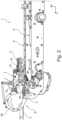
- Figure 1 shows a perspective view on an automatic bundling tool device 1, ABT 1, for bundling a bundling good by means of a one-piece tie 2, OPT 2.
- the one-piece tie 2 of the present example is a loose cable tie.
- the OPT 2 has a tip 2a, strap 2b, and a head 2c.
- the ABT 1 further comprises a holding unit 3 configured to receive, hold, and release the respective OPT 2 which is provided to the ABT 1 from an external reservoir of OPTs.
- the holding unit 3 is provided in the form of a slider on which two gripping elements 3a and 3a' are mounted.
- the gripping elements 3a, 3a' can be moved from an open position, in which the head 2c of the OPT 2 can be received to a holding position in which a contour 3b defined by the shapes of the individual gripping elements 3a and 3a' establishes an at least partial form fit connection to the head 2c of the OPT 2.
- the two gripping elements 3a and 3a' can be moved linearly traversely to a forward direction LO, that is, in a z-direction, in the present figure, where the forward direction corresponds to the x-direction.
- the ABT 1 further comprises a motion guiding unit 4 configured to guide a motion of the holding unit 3 between a receiving position of the holding unit 3, where the holding unit 3 receives, during intended use, the respective OPT 2 and a releasing position of the holding unit 3 where the holding unit releases, during intended use, the respective OPT 2.
- the motion guiding unit 4 is shown in the receiving position.
- the motion guiding unit 4 approaching the releasing position is shown in Fig. 2 .
- the motion guiding unit 4 is a linear motion guiding unit 4 with a linear rail 4a which defines an OPT track 5.
- the ABT 1 also comprises a claw unit 6 configured to guide the strap 2b of the respective OPT 2 around the bundling good.
- the claw unit 6 comprises an upper jaw as first claw element 6a, which is static as it is not movable with respect to a housing or handle of the ABT 1 and the motion guiding unit 4.
- the claw unit 6 further comprises a lower jaw as second claw element 6b, which can be moved, in particular, opened and closed in order to form a guide around the bundling good for the loop of the strap 2b.
- the ABT of the present embodiment features a tip guiding unit 7 with at least one guiding flap element 7a configured to guide the tip 2a, and thus also the strap 2b of the respective OPT 2 towards an entrance 6c of the claw unit 6 when the respective OPT 2 is moved in the forward direction LO towards the releasing position of the holding unit 3 by the holding unit 3 moving from the receiving position to the releasing position.
- At least one distance here at least two distances are measured perpendicular to the OPT track 5.
- the first distance is measured as a y-distance in the y-direction, which is a direction of thickness of the respective OPT 2.
- the second distance is measured as a z-distance in a direction of width of the respective OPT 2.
- the at least one guiding flap element 7a forms a section of a funnel narrowing towards the claw unit 6 (in the forward direction LO), where the narrow end of the funnel shapes a gate 7d (i.e. forms said gate 7d or part of it) that is configured to guide the tip 2a to or into the entrance 6c of the claw unit 6.
- the guiding flap element 7a comprises an upper inner (deflecting) surface 7b as well as two side inner (deflecting) surfaces 7c, 7c', with the inner side surfaces 7c, 7c' converging in the positive x-direction, that is, the forward direction LO, and the upper inner surface 7b converging towards the OPT track 4a in the same direction. This is shown in more detail in Fig. 4 .
- the at least one guiding flap element 7a is arranged movably relative to the body of the ABT 1. It is movable between a guiding position, which is shown in Fig. 1 , and a clearing position, which is shown in Fig. 2 . In the guiding position, and end 7e of the at least one guiding flap element 7 proximal to the claw unit 6, the proximal end 7e, is forming said gate 7d or part of the gate 7d which guides the tip 2a of the OPT 2 to or into the entrance 6c of the claw unit 6.
- a distance dp of the proximal end 7e and the OPT track 5 or, correspondingly, the OPT 2 moved along the OPT track 5 is increased as compared to the guiding position.
- the distance dp may be increased such that holding unit 3 can move into space taken by the guiding flap element 7a before.
- the movement of the at least one guiding flap element 7a can be a linear movement or, as shown in the present example, a rotational movement.
- the at least one guiding flap element 7a is arranged rotatably about the respective rotation axis R with, in the present example, the rotation axis R running traversely to the OPT track 5. It is advantageous if a distance dr of the rotation axis and the OPT track 5 is nonzero, for instance, more than at least five times or more than at least ten times the thickness of the OPTs to be processed by the ABT 1.
- the rotation axis R is also running parallel to the width direction of the respective OPT 2.
- An alternative solution would be to arrange two movable guiding flap elements, preferably each arranged rotatably around the respective rotation axis, with the two rotation axes running in parallel and the guiding flap elements opening up sideways, that is, in the z-direction.
- the shown embodiment comprises less movable parts, depending on the shape of the holding unit and available space, such an alternative embodiment might be chosen for the respective application at hand.
- the one or more rotation axes R are preferably arranged, in the x-direction, between claw unit 6 and holding unit 3 when in the holding unit 3 is in the receiving position.
- the figures also show that, alternatively or in addition, a part (e.g. a half, as viewed in x- direction) of the guiding flap element 7a comprising the proximal end 7e may further away from the one or more rotation axes R than another part (e.g. the other half) of the guiding flap element 7a comprising an end opposite (in x-direction) to the proximal end 7e.
- the at least one guiding flap element 7a is configured to be held in the guiding position by a spring element 8, and to be moved into the clearing position by the holding unit 3 approaching the claw unit 6, in the present example by a mechanical interaction of the holding unit 3 with the at least one guiding flap element 7a. Furthermore, in the example shown, the at least one guiding flap element 7a is configured to be locked in the clearing position by a locking element 9, which is configured to release the at least one guiding flap element 7a when the distance between the holding unit 3 and the at least one guiding flap element 7a in the forward direction, that is, in the x-direction, exceeds a preset distance when the holding unit 3 is retracted from releasing position to receiving position.
- the inner surfaces 7b, 7c, and 7c' may be smooth surfaces and/or coated surfaces.
- the functioning of the ABT 1 shown here can be described by the following exemplary method steps.
- the OPT 2 is provided to the ABT 1, from an external reservoir.
- the OPT 2 is fixed its position, for example by a form fit connection to the two gripping elements 3a and 3a'.
- the respective OPT 2 can be moved towards the bundling good (not shown), with the tip 2a of the respective OPT 2 ahead, in the forward direction LO, which is a positive x-direction.
- the OPT 2 is not an ideal straight OPT shown in the present Figs., but a bent OPT 2, which is an OPT 2 with an unvoluntaryly nonstraight strap 2b such that there is a nonzero distance between the tip 2a and the OPT track 5 the tip 2a is supposed to take in order to meet the entrance 6c without any additional interaction.
- the tip 2a and the strap 2b of the respective OPT 2 are guided towards the entrance 6c of the claw unit 6 by the at least one guiding flap 7a of the tip guiding unit 7 which is positioned in the guiding position (as shown in Fig. 3 ).
- the at least one guiding flap element 7a is moved in a clearing position further away from the OPT track 5 than in the guiding position (as shown in Fig. 2 ).
- the holding unit 3 can approach the entrance 6c of the claw unit 6 to the same extent than without the tip guiding unit 7. Consequently, the strap 2b is guided around the bundling good by the claw elements 6a and 6b back through head 2c of the respective OPT 2 by the claw unit 6, and forms a loop as usual.
- bent OPTs, in particular loose cable ties can be processed reliably and do not lead to failure of the automatic bundling process.
Landscapes
- Engineering & Computer Science (AREA)
- Mechanical Engineering (AREA)
- Basic Packing Technique (AREA)
Applications Claiming Priority (1)
| Application Number | Priority Date | Filing Date | Title |
|---|---|---|---|
| DE202022002179.8U DE202022002179U1 (de) | 2022-10-06 | 2022-10-06 | Automatische Bündelwerkzeugvorrichtung mit Führungseinheit für verformte und/oder lose einteilige Bänder |
Publications (1)
| Publication Number | Publication Date |
|---|---|
| EP4375202A1 true EP4375202A1 (de) | 2024-05-29 |
Family
ID=89808500
Family Applications (1)
| Application Number | Title | Priority Date | Filing Date |
|---|---|---|---|
| EP23201566.9A Pending EP4375202A1 (de) | 2022-10-06 | 2023-10-04 | Automatische bündelwerkzeugvorrichtung mit führungseinheit für deformierte und/oder lose einstückige bänder |
Country Status (6)
| Country | Link |
|---|---|
| US (1) | US12583640B2 (de) |
| EP (1) | EP4375202A1 (de) |
| JP (1) | JP2024055832A (de) |
| KR (1) | KR20240048495A (de) |
| CN (1) | CN117842435A (de) |
| DE (1) | DE202022002179U1 (de) |
Families Citing this family (2)
| Publication number | Priority date | Publication date | Assignee | Title |
|---|---|---|---|---|
| EP4163215A1 (de) | 2021-10-01 | 2023-04-12 | HellermannTyton GmbH | Für eine reihe von einzelnen banddicken optimierte automatische bündelungswerkzeugvorrichtung |
| DE202024106879U1 (de) * | 2024-11-27 | 2026-03-02 | Hellermanntyton Gmbh & Co Kg | Aktuatorlose Ausrichtungsänderungsvorrichtung für einen Einteil-Binder |
Citations (3)
| Publication number | Priority date | Publication date | Assignee | Title |
|---|---|---|---|---|
| US5417252A (en) * | 1992-11-02 | 1995-05-23 | Bowthorpe Plc | Tool for binding an object, by means of a strip |
| US5845681A (en) * | 1996-10-10 | 1998-12-08 | Paul Hellermann Gmbh | Arrangement for tying an article, in particular a cable harness |
| EP3712076A1 (de) | 2018-02-02 | 2020-09-23 | Shenzhen Swift Automation Technology Co., Ltd. | Vorrichtung zum zuführen, verteilen und schieben eines bindewerkzeugs, automatisches bindewerkzeug und automatisches bindeverfahren |
Family Cites Families (111)
| Publication number | Priority date | Publication date | Assignee | Title |
|---|---|---|---|---|
| GB885371A (en) | 1959-04-18 | 1961-12-28 | Ver Metaalverpakking Mij Nv | Machine for securing a metal strap around a container, box, package or the like |
| US3865156A (en) | 1973-09-17 | 1975-02-11 | Panduit Corp | Powered strap tensioning and severing tool |
| GB2006152B (en) * | 1977-09-06 | 1982-01-20 | Amp Inc | Tool for applying bundle ties |
| US4495972A (en) | 1980-02-27 | 1985-01-29 | Bowthorpe-Hellermann Limited | Automatic tie gun |
| US4371010A (en) | 1980-11-03 | 1983-02-01 | Thomas & Betts Corporation | Bundling tie applying tool |
| DE3220446A1 (de) | 1982-05-29 | 1984-01-26 | Hoesch Werke Ag, 4600 Dortmund | Vorschub- und spannvorrichtung fuer ein um ein packstueck zu spannendes umreifungsband |
| US4790225A (en) | 1982-11-24 | 1988-12-13 | Panduit Corp. | Dispenser of discrete cable ties provided on a continuous ribbon of cable ties |
| US4534817A (en) | 1983-04-08 | 1985-08-13 | Sullivan Denis P O | Automatic bundle-tying tool |
| US4793385A (en) | 1986-08-22 | 1988-12-27 | Tyton Corporation | Handheld tensioning and cut-off tool |
| USD306390S (en) | 1986-09-26 | 1990-03-06 | Tyton Corporation | Hand-held wire wrapping tool |
| GB8907143D0 (en) | 1989-03-30 | 1989-05-10 | Bowthorpe Hellermann Ltd | Automatic tie gun |
| DE8913514U1 (de) | 1989-11-15 | 1991-03-21 | Paul Hellermann GmbH, 25421 Pinneberg | Vorrichtung zum Umschlingen und Spannen eines Bandes um einen Gegenstand |
| US4997011A (en) | 1990-01-11 | 1991-03-05 | Tyton Corporation | Hand held tie tensioning and cut-off tool |
| US5205328A (en) | 1992-03-18 | 1993-04-27 | Panduit Corp. | Portable cable tie tool |
| US5287802A (en) | 1992-12-14 | 1994-02-22 | Signode Corporation | Strap severing and ejecting mechanism for strapping machine |
| US5492156A (en) | 1994-03-10 | 1996-02-20 | Tyton Corporation | Hand held tie tensioning and cut-off tool |
| US5595220A (en) | 1995-01-18 | 1997-01-21 | Panduit Corp. | Portable cable tie installation tool |
| US5618937A (en) | 1995-03-15 | 1997-04-08 | Merck & Co., Inc. | Process to make HIV protease inhibitor from (2S)-4-picolyl-2-piperazine-t-butylcarboxamide |
| JP3655954B2 (ja) | 1995-10-13 | 2005-06-02 | タイトン株式会社 | 可搬式電動結束バンド引締め装置 |
| JPH09240617A (ja) | 1996-03-08 | 1997-09-16 | Kioritz Corp | 梱包機 |
| DE69735513T2 (de) | 1996-08-28 | 2006-11-09 | Thomas & Betts Corp., Memphis | Kabelbinder-Installationswerkzeug |
| DE29617650U1 (de) | 1996-10-10 | 1998-02-05 | Paul Hellermann GmbH, 25421 Pinneberg | Kabelbindewerkzeug |
| IT1286370B1 (it) | 1996-10-31 | 1998-07-08 | Thomas & Betts Corp | Utensile automatico per la installazione di fascette serracavi |
| US5809873A (en) | 1996-11-18 | 1998-09-22 | Ovalstrapping, Inc. | Strapping machine having primary and secondary tensioning units and a control system therefor |
| US5769133A (en) | 1997-04-08 | 1998-06-23 | Tyton-Hellermann Corp. | Power actuated handheld tensioning and cutoff tool |
| US5921290A (en) | 1997-04-08 | 1999-07-13 | Tyton Hellermann Corporation | Handheld tensioning and cutoff tool |
| JP2000103407A (ja) | 1998-09-30 | 2000-04-11 | Shin Meiwa Ind Co Ltd | バンド結束機およびバンド結束機の制御方法 |
| US6302157B1 (en) | 1999-05-14 | 2001-10-16 | Avery Dennison Corporation | Cable tie installation tool |
| US6401766B1 (en) | 1999-07-23 | 2002-06-11 | Max Co., Ltd. | Binding machine for reinforcing bars |
| US6354336B1 (en) | 1999-10-12 | 2002-03-12 | Panduit Corp. | Automatic cable tie tool having a front jaw locking mechanism |
| US6206053B1 (en) | 1999-11-01 | 2001-03-27 | Panduit Corp. | Cable tie tensioning and severing tool |
| ES2182743T3 (es) | 2000-03-09 | 2003-03-16 | Hellermann Tyton Gmbh | Dispositivo para atar objetos como haces de cables. |
| US6530615B2 (en) | 2001-01-17 | 2003-03-11 | Syron Engineering & Mfg., Llc | Workpiece gripper |
| ES2254271T3 (es) | 2001-02-12 | 2006-06-16 | Hellermann Tyton Gmbh | Util para atar un objeto, especialmente un mazo de cables. |
| DE50100795D1 (de) | 2001-02-12 | 2003-11-20 | Hellermann Tyton Gmbh | Werkzeuganordnung zum Binden eines Gegenstands, insbesondere eines Kabelbaums |
| DE50115470D1 (de) | 2001-02-12 | 2010-06-17 | Hellermann Tyton Gmbh | Anordnung zum Binden von Gegenständen mittels einer Bandschlaufe |
| ATE247025T1 (de) | 2001-02-12 | 2003-08-15 | Hellermann Tyton Gmbh | Bindewerkzeug |
| ATE316037T1 (de) | 2001-02-12 | 2006-02-15 | Hellermann Tyton Gmbh | Anordnung zum binden eines gegenstandes, insbesondere kabelbaums |
| US6481467B2 (en) | 2001-03-15 | 2002-11-19 | Band-It-Idex, Inc. | Powered band clamping under electrical control |
| US6543341B2 (en) | 2001-07-12 | 2003-04-08 | Illinois Tool Works, Inc. | Strapping machine with strapping head sensor |
| WO2003010048A1 (en) | 2001-07-19 | 2003-02-06 | Max Co., Ltd. | Reinforcing steel bar tying machine |
| JP3536045B2 (ja) | 2002-01-21 | 2004-06-07 | タイトン株式会社 | 結束装置 |
| JP2004142813A (ja) | 2002-10-28 | 2004-05-20 | Max Co Ltd | 鉄筋結束機 |
| US6840289B2 (en) | 2002-10-29 | 2005-01-11 | Panduit Corp. | Pneumatic cable tie tool |
| USD473773S1 (en) | 2002-10-29 | 2003-04-29 | Panduit Corp. | Cable tie installation tool |
| US6976422B2 (en) | 2003-06-06 | 2005-12-20 | Illinois Tool Works, Inc. | Strapping machine with automatic strap clearing and reloading |
| USD491430S1 (en) | 2003-07-07 | 2004-06-15 | Thomas & Betts International, Inc. | Cable tie installation tool |
| USD510244S1 (en) | 2003-07-07 | 2005-10-04 | Thomas & Betts International, Inc. | Cable tie installation tool |
| US6981528B2 (en) | 2003-10-07 | 2006-01-03 | Thomas & Betts International, Inc. | Anti-jam tensioning gear mechanism for automatic tie tool head |
| CH696398A5 (de) | 2003-11-21 | 2007-05-31 | Automatic Taping Systems | Verfahren zum Banderolieren von gestapeltem, weichem und/oder empfindlichem Packgut |
| DE602005015370D1 (de) | 2004-02-13 | 2009-08-27 | Thomas & Betts Internat Inc A | Kabelbindewerkzeug mit modularem Werkzeugkopf |
| JP4624124B2 (ja) | 2004-02-13 | 2011-02-02 | トーマス・アンド・ベッツ・インターナショナル・インコーポレーテッド | ケーブル・タイ・ツールのための張力と抗反跳の機構 |
| ES2290843T3 (es) | 2004-02-13 | 2008-02-16 | Thomas & Betts International, Inc. | Contador de ciclos para herramienta de instalacion de sujeta-cables. |
| US7299830B2 (en) | 2004-06-04 | 2007-11-27 | Panduit Corp. | Low tension flush cut-off cable tie installation tool |
| JP4548584B2 (ja) | 2004-07-16 | 2010-09-22 | マックス株式会社 | 鉄筋結束機 |
| US7124787B2 (en) | 2004-08-18 | 2006-10-24 | Hellermanntyton Corporation | Pneumatic cable tie installation tool |
| USD543811S1 (en) | 2005-04-20 | 2007-06-05 | Hellermanntyton Corporation | Pneumatic tensioning and cutoff tool |
| US7165379B1 (en) | 2005-07-25 | 2007-01-23 | Tony Lai | Forward-reverse tension mechanism for packing machine |
| WO2007123547A1 (en) | 2006-04-26 | 2007-11-01 | Hellermanntyton Corporation | Jaw assembly for cable tie tool |
| US8528603B2 (en) | 2007-09-21 | 2013-09-10 | Panduit Corp. | Tie guide channel for cable tie installation tool |
| US7591451B2 (en) | 2007-11-13 | 2009-09-22 | Hellermanntyton Corporation | Bundle tie tensioning clutch |
| US8051881B2 (en) | 2008-04-01 | 2011-11-08 | Panduit Corp. | Metal retained tension tie tool |
| US10518914B2 (en) | 2008-04-23 | 2019-12-31 | Signode Industrial Group Llc | Strapping device |
| JP5369846B2 (ja) | 2008-05-19 | 2013-12-18 | マックス株式会社 | 鉄筋結束機におけるワイヤリールのブレーキ機構 |
| CN101353088B (zh) | 2008-06-20 | 2010-07-28 | 蔡昌开 | 钢筋捆扎机 |
| CN101486385B (zh) | 2009-02-06 | 2011-08-17 | 浙江兄弟包装机械有限公司 | 半自动捆扎机 |
| KR101117457B1 (ko) | 2010-02-25 | 2012-02-29 | 홍준표 | 버려지는 부분이 없는 길이 조절 케이블 타이 |
| CN102275649B (zh) | 2011-05-26 | 2013-05-01 | 东莞市胜蓝电子有限公司 | 自动扎带束线机 |
| EP2726229B1 (de) | 2011-06-30 | 2016-05-04 | Hellermanntyton Corporation | Spann- und schneidewerkzeug für kabelbinder |
| USD692738S1 (en) | 2011-06-30 | 2013-11-05 | Hellermanntyton Corporation | Cable tie tensioning and cut-off tool |
| CH705744A2 (de) | 2011-11-14 | 2013-05-15 | Illinois Tool Works | Umreifungsvorrichtung. |
| US10450096B2 (en) | 2011-11-14 | 2019-10-22 | Hellermanntyton Co., Ltd. | Manual bundling tool |
| US9085070B2 (en) | 2012-04-16 | 2015-07-21 | Signode Industrial Group Llc | Tensioner/cutter tool for hose clamps |
| CN202670128U (zh) | 2012-06-05 | 2013-01-16 | 上海古鳌电子科技股份有限公司 | 捆扎带传动及张力调整机构 |
| CN104487351A (zh) | 2012-08-09 | 2015-04-01 | 海尔曼太通株式会社 | 手动捆扎工具 |
| US9938029B2 (en) | 2012-09-24 | 2018-04-10 | Signode Industrial Group Llc | Strapping device having a pivotable rocker |
| TR201901689T4 (tr) | 2013-05-29 | 2019-02-21 | Nisshin Seifun Group Inc | Çubuk şeklinde cisimleri bağlama cihazı ve çubuk şeklinde bir cismin bağlanmış bir yığınını üretmek için yöntem. |
| US9481102B1 (en) | 2013-09-10 | 2016-11-01 | The Boeing Company | Spacer for a cable tie tensioning and severing tool |
| JP6220881B2 (ja) | 2013-09-25 | 2017-10-25 | ヘラマンタイトン株式会社 | 結束バンドの固定構造および結束工具 |
| DE102013222924A1 (de) | 2013-11-11 | 2015-05-28 | Hellermann Tyton Gmbh | Portables Kabelbindewerkzeug |
| FR3016346B1 (fr) | 2014-01-13 | 2016-01-08 | Rech S Et Conceptions A R C Atel | Dispositif de ficelage ameliore |
| DE102014103334A1 (de) | 2014-03-12 | 2015-09-17 | Mosca Gmbh | Verfahren zur Steuerung der Parameter eines Umreifungssystems |
| US10308383B2 (en) | 2014-07-21 | 2019-06-04 | Signode Industrial Group Llc | Electrically powered combination hand-held strapping tool |
| MX380306B (es) | 2014-12-12 | 2025-03-04 | Hellermanntyton Corp | Mecanismo compuesto de calibración y tensión de herramienta para cortar y tensar lazos de cable. |
| WO2016123358A1 (en) | 2015-01-28 | 2016-08-04 | Ideal Industries, Inc. | Apparatus for tensioning a cable lacing tape device |
| USD758155S1 (en) | 2015-02-13 | 2016-06-07 | Panduit Corp. | Cable tie tool |
| CN107472575B (zh) | 2015-08-11 | 2019-04-23 | 许修义 | 一种自动扎带工具的尾料排出结构 |
| US20170057674A1 (en) | 2015-09-01 | 2017-03-02 | Hellermanntyton Corporation | Pawl shroud with textured surface |
| US20170174374A1 (en) | 2015-12-22 | 2017-06-22 | Signode Industrial Group Llc | Tool and tool setting management system and method configured to pair with the tool to change how the tool can function |
| CN106742178A (zh) | 2016-02-05 | 2017-05-31 | 许修义 | 一种自动导引穿孔机构 |
| JP1564309S (de) | 2016-04-06 | 2016-11-28 | ||
| JP6640996B2 (ja) | 2016-04-18 | 2020-02-05 | ヘラマンタイトン株式会社 | 手動結束工具 |
| JP6640995B2 (ja) | 2016-04-18 | 2020-02-05 | ヘラマンタイトン株式会社 | 手動結束工具 |
| US20170334587A1 (en) | 2016-05-19 | 2017-11-23 | Delphi Technologies, Inc. | Cable Tie Tensioning And Cut Off Tool |
| CN206579887U (zh) | 2017-03-08 | 2017-10-24 | 宁波安红汽配有限公司 | 带收带盒棘轮绑带拉紧器 |
| CN107380564A (zh) | 2017-09-03 | 2017-11-24 | 许修义 | 一种用于扎带工具的自动检测方法及结构 |
| FR3072080B1 (fr) | 2017-10-09 | 2019-11-01 | Hellermanntyton Gmbh | Appareil automatique manuel pour poser des colliers de serrage |
| FR3073503B1 (fr) | 2017-11-14 | 2019-11-22 | Hellermanntyton Gmbh | Appareil automatique manuel pour poser des colliers de serrage |
| WO2019148723A1 (zh) | 2018-02-02 | 2019-08-08 | 许修义 | 一种滑块定位机构及具有该滑块定位机构的自动扎带工具 |
| US20190248521A1 (en) | 2018-02-12 | 2019-08-15 | Panduit Corp. | Portable Cable Tie Tool |
| CN108791998B (zh) | 2018-06-27 | 2020-01-21 | 芜湖博康机电有限公司 | 一种扎带枪 |
| TWM575789U (zh) | 2018-12-11 | 2019-03-21 | 華偉實業股份有限公司 | 束帶緊固切斷工具 |
| USD885861S1 (en) | 2018-12-13 | 2020-06-02 | Hua Wei Industrial Co., Ltd. | Cable tie tool |
| IT201900006288A1 (it) | 2019-04-24 | 2020-10-24 | Itatools S R L | Reggiatrice |
| US11027902B2 (en) | 2019-06-12 | 2021-06-08 | Hellermanntyton Corporation | Integrated release feature for pawl-latching devices |
| US11511894B2 (en) | 2019-09-26 | 2022-11-29 | Hellermanntyton Corporation | Cable tie application tool |
| KR102267779B1 (ko) | 2020-07-20 | 2021-06-22 | 박상철 | 하니스 제조 장치 |
| CN112660456B (zh) | 2020-12-10 | 2022-03-29 | 国网浙江省电力有限公司衢州供电公司 | 扎带自动绑扎机 |
| EP4163215A1 (de) | 2021-10-01 | 2023-04-12 | HellermannTyton GmbH | Für eine reihe von einzelnen banddicken optimierte automatische bündelungswerkzeugvorrichtung |
| US12157240B2 (en) | 2021-10-26 | 2024-12-03 | Hellermanntyton Corporation | Severing a cable tie with a rounded cut |
| DE202022102045U1 (de) | 2022-04-14 | 2023-07-19 | Hellermanntyton Gmbh | Automatische Bündelwerkzeugeinrichtung, ABT, für das Bündeln eines Bündelgutes mit einem Einteil-Binder mit Qualitätsüberwachung |
-
2022
- 2022-10-06 DE DE202022002179.8U patent/DE202022002179U1/de active Active
-
2023
- 2023-10-04 EP EP23201566.9A patent/EP4375202A1/de active Pending
- 2023-10-05 JP JP2023173604A patent/JP2024055832A/ja active Pending
- 2023-10-05 KR KR1020230132671A patent/KR20240048495A/ko active Pending
- 2023-10-05 US US18/481,828 patent/US12583640B2/en active Active
- 2023-10-09 CN CN202311301899.6A patent/CN117842435A/zh active Pending
Patent Citations (3)
| Publication number | Priority date | Publication date | Assignee | Title |
|---|---|---|---|---|
| US5417252A (en) * | 1992-11-02 | 1995-05-23 | Bowthorpe Plc | Tool for binding an object, by means of a strip |
| US5845681A (en) * | 1996-10-10 | 1998-12-08 | Paul Hellermann Gmbh | Arrangement for tying an article, in particular a cable harness |
| EP3712076A1 (de) | 2018-02-02 | 2020-09-23 | Shenzhen Swift Automation Technology Co., Ltd. | Vorrichtung zum zuführen, verteilen und schieben eines bindewerkzeugs, automatisches bindewerkzeug und automatisches bindeverfahren |
Also Published As
| Publication number | Publication date |
|---|---|
| JP2024055832A (ja) | 2024-04-18 |
| DE202022002179U1 (de) | 2024-01-11 |
| CN117842435A (zh) | 2024-04-09 |
| US12583640B2 (en) | 2026-03-24 |
| US20240116661A1 (en) | 2024-04-11 |
| KR20240048495A (ko) | 2024-04-15 |
Similar Documents
| Publication | Publication Date | Title |
|---|---|---|
| EP4375202A1 (de) | Automatische bündelwerkzeugvorrichtung mit führungseinheit für deformierte und/oder lose einstückige bänder | |
| EP4183699A1 (de) | Automatische bündelwerkzeugvorrichtung zum bündeln eines bündelguts mittels verschieden geformter einstückiger streifen | |
| EP2825013B1 (de) | Automatisierte bandeinstellungsvorrichtung | |
| EP3328177B1 (de) | Komponentenzuführer | |
| US5845681A (en) | Arrangement for tying an article, in particular a cable harness | |
| US5417252A (en) | Tool for binding an object, by means of a strip | |
| US7150222B2 (en) | Apparatus longitudinally strapping a package, in particular a stack of newspapers, magazines or the like | |
| CN116002121A (zh) | 通过不同形状一体式扎带捆扎成捆物品的自动捆扎工具装置 | |
| JP2002255112A (ja) | 特にケーブルハーネスのような物体を結束する装置 | |
| US5050649A (en) | Strap and tool for looping and clamping around elongate articles | |
| JP2683722B2 (ja) | グリッパ形織機 | |
| JP3517340B2 (ja) | 結束工具 | |
| EP0282986B1 (de) | Fadenführungsvorrichtung | |
| US6019142A (en) | Tool and arrangement for fastening an article by means of a band | |
| US20070157989A1 (en) | Inserting rapier for a rapier weaving machine | |
| EP4393829A1 (de) | Zuführvorrichtung zum führen und bereitstellen von einstückigen bändern | |
| JP3570667B2 (ja) | ゴム栓挿入装置及びゴム栓挿入方法 | |
| KR20230057292A (ko) | 원피스 고정 타이를 자동 번들링 툴 장치에 공급하기 위한 가변 저장소 장치 | |
| RS67568B1 (sr) | Uređaj i postupak za upredanje pojedinačnih vodova | |
| KR970001699Y1 (ko) | 회전자함침기의 회전자파지아암 | |
| CN112323229B (zh) | 穿经梭夹,穿经机以及穿引经纱的方法 | |
| JPH01254112A (ja) | 植毛機のピッカー | |
| US6352087B1 (en) | Insertion gripper for a rapier loom | |
| EP0200077A2 (de) | Vorrichtung zur Fadenbruchbehebung in einer Offen-End-Spinnmaschine | |
| JPS5612269A (en) | Cutting/guiding mechanism for supplied thread in automatic winder |
Legal Events
| Date | Code | Title | Description |
|---|---|---|---|
| PUAI | Public reference made under article 153(3) epc to a published international application that has entered the european phase |
Free format text: ORIGINAL CODE: 0009012 |
|
| STAA | Information on the status of an ep patent application or granted ep patent |
Free format text: STATUS: THE APPLICATION HAS BEEN PUBLISHED |
|
| AK | Designated contracting states |
Kind code of ref document: A1 Designated state(s): AL AT BE BG CH CY CZ DE DK EE ES FI FR GB GR HR HU IE IS IT LI LT LU LV MC ME MK MT NL NO PL PT RO RS SE SI SK SM TR |
|
| STAA | Information on the status of an ep patent application or granted ep patent |
Free format text: STATUS: REQUEST FOR EXAMINATION WAS MADE |
|
| 17P | Request for examination filed |
Effective date: 20240906 |
|
| RBV | Designated contracting states (corrected) |
Designated state(s): AL AT BE BG CH CY CZ DE DK EE ES FI FR GB GR HR HU IE IS IT LI LT LU LV MC ME MK MT NL NO PL PT RO RS SE SI SK SM TR |
|
| RAP3 | Party data changed (applicant data changed or rights of an application transferred) |
Owner name: HELLERMANNTYTON GMBH & CO. KG |