EP4251552B1 - Kabinenboden für eine aufzugskabine und verfahren zur montage einer aufzugskabine - Google Patents
Kabinenboden für eine aufzugskabine und verfahren zur montage einer aufzugskabine Download PDFInfo
- Publication number
- EP4251552B1 EP4251552B1 EP21816431.7A EP21816431A EP4251552B1 EP 4251552 B1 EP4251552 B1 EP 4251552B1 EP 21816431 A EP21816431 A EP 21816431A EP 4251552 B1 EP4251552 B1 EP 4251552B1
- Authority
- EP
- European Patent Office
- Prior art keywords
- base part
- floor
- car
- elevator
- height
- Prior art date
- Legal status (The legal status is an assumption and is not a legal conclusion. Google has not performed a legal analysis and makes no representation as to the accuracy of the status listed.)
- Active
Links
Images

Classifications
-
- B—PERFORMING OPERATIONS; TRANSPORTING
- B66—HOISTING; LIFTING; HAULING
- B66B—ELEVATORS; ESCALATORS OR MOVING WALKWAYS
- B66B11/00—Main component parts of lifts in, or associated with, buildings or other structures
- B66B11/02—Cages, i.e. cars
- B66B11/0226—Constructional features, e.g. walls assembly, decorative panels, comfort equipment, thermal or sound insulation
-
- B—PERFORMING OPERATIONS; TRANSPORTING
- B66—HOISTING; LIFTING; HAULING
- B66B—ELEVATORS; ESCALATORS OR MOVING WALKWAYS
- B66B19/00—Mining-hoist operation
-
- B—PERFORMING OPERATIONS; TRANSPORTING
- B66—HOISTING; LIFTING; HAULING
- B66B—ELEVATORS; ESCALATORS OR MOVING WALKWAYS
- B66B19/00—Mining-hoist operation
- B66B19/04—Installing or removing mining-hoist cars, cages, or skips
Definitions
- the invention relates to a cabin floor for an elevator cabin and a method for assembling an elevator cabin.
- Elevator systems for transporting people and goods contain elevator cabins that can be moved up and down in an elevator shaft.
- the elevator cabins can be moved using support elements, for example in the form of support ropes or support belts, by means of a drive unit.
- No cabin frames are required for self-supporting elevator cabins.
- To assemble such elevator cabins the cabin floor is brought into the shaft pit. The cabin side walls and the ceiling can then be installed to complete the elevator cabin. It often happens that the shaft floor is not completely level. There is therefore a need to compensate for such unevenness in the floor or to level the cabin floor for other reasons.
- a car floor for an elevator car has become known.
- the car floor is part of an elevator car component arrangement in which the car floor is accommodated in a stacked state together with a car ceiling unit for packaging and transport.
- the elevator car component arrangement comprises connecting links with adjustment bushing sections which must be rotated by 180°. After the connecting link has been rotated, the adjustment bushing section shifts from an upward orientation to a downward orientation.
- the adjustment bushing section comprises a tubular section and a bolt section which can be inserted into the tubular section and which can be pulled out of the tubular section. Via a bolt head section of the bolt section, the position of the bolt section can be adjusted so that when the car floor unit is placed on the shaft pit surface, the car floor unit is horizontal.
- the cabin floor for an elevator cabin comprises a flat base part for defining a walking area for passengers in the interior of the elevator cabin.
- the cabin floor can be leveled in a simple and efficient manner by arranging mounting feet on the base part, whereby at least one of the mounting feet and preferably each of the mounting feet is a height-adjustable mounting foot for aligning the base part in a horizontal position.
- Mounting foot receptacles for receiving the mounting feet can also be provided on the base part, so that mounting feet can be arranged on the base part.
- the cabin floor can be attached to a shaft floor of an elevator shaft of the elevator via the mounting feet during an assembly phase. Elevator system must be supported or parked.
- the height-adjustable mounting foot can be used to adjust the local vertical position of the base part in the area of the respective mounting foot. In other words, the height adjustment affects the distance between the base part and the shaft floor.
- this distance can be increased or reduced and thus the desired height can be set.
- the mounting feet can be removed again if necessary after the assembly phase has been completed.
- the mounting feet can also be permanently attached to the base part.
- the base part is, for example, a component in composite structure or sandwich construction such as that used in EP 1 004 538 A1
- the base part comprises a base plate, a cover plate and a composite structure core in between.
- the composite structure core which forms the connection between the base and cover plates, can be constructed from a large number of upright, crossing slats in the form of a grating, which are firmly connected to the base and cover plates in a suitable manner.
- the base part can also be constructed in a different way.
- the core could be formed by one or more layers of honeycomb-like structures.
- the base part can have a rectangular shape in plan view.
- four mounting feet are provided, which are arranged in the corner areas of the base part.
- further mounting foot receptacles can be provided.
- the arrangement in the corner area includes an arrangement of the mounting feet near or adjacent to the corners of the base part. It is therefore not necessary for the mounting feet to be directly on the geometric corner.
- the mounting feet can be positioned inside or outside the vertical projection of the base part.
- the cabin floor can be supported on the shaft floor using four height-adjustable mounting feet.
- the mounting feet centrally on the four rectangular sides of the base part.
- the respective height-adjustable mounting foot is designed in such a way and can preferably be operated manually so that the height can be adjusted from the base part. Instead of manual operation, it is also conceivable to carry out the height adjustment using drives. Motor-driven mounting feet of this kind could also be operated by remote control.
- the respective height-adjustable mounting foot can be moved up and down in a vertical direction using mechanical means, for example a screw gear, to adjust the height.
- mechanical means for example a screw gear
- other mechanical means can also be used, such as a ratchet mechanism, a slide guide, a crank device, a locking device, a telescopic rod or a slide guide.
- hydraulic or pneumatic means for adjusting the height of the mounting foot are also conceivable.
- the mounting foot can be height-adjustable using a threaded spindle.
- Such threaded spindles are inexpensive and are characterized by robustness and ease of use.
- the height-adjustable mounting foot, which can be operated using the threaded spindle, can thus be easily set to the desired height.
- the respective height-adjustable mounting foot can have a threaded rod that is or can be received in an internal thread assigned to the base part and corresponding to the threaded rod to form the threaded spindle.
- the mounting foot can thus be designed as a spindle screw.
- the threaded rod extends, during the assembly phase and when it is arranged on the base part, preferably in a vertical direction.
- the internal thread can form the previously mentioned mounting foot receptacle.
- Spacer elements for positioning the mounting feet outside of a vertical projection of the base part can be attached or molded onto the side of the base part.
- the spacer elements can contain the internal threads in which threaded rods of the mounting feet are received or can be received.
- the spacer elements are, for example, angle pieces that are attached to vertical side wall sections of the base part.
- the base part can have internal threads integrated therein, into which the corresponding threaded rods for forming the height-adjustable mounting feet are received or can be received.
- the base part can have holes on the inside in the corner areas into which the threaded rods are passed, whereby the holes for forming the threaded spindle can have internal threads at least in sections.
- the aforementioned base plate of the base part can have a hole for each mounting foot into which the threaded rods are passed through or inserted.
- stamp-like support elements are arranged on the lower ends of the respective threaded rods facing the shaft floor to increase the contact surface with the shaft floor.
- These support elements can be connected to the threaded rods in an articulated manner via ball bearings, for example.
- engagement or actuation means such as tool holders for screwdrivers or wrenches, adjusting screws with separate rotary handles, wing screws or toggle screws can be arranged, which simplifies the manual operation of the threaded spindle for adjusting the height of the mounting foot.
- the spirit level can be attached to the base part at least temporarily or permanently.
- the spirit level can be a circular spirit level or a tubular spirit level.
- the spirit level can be attached to the base part by means of an adhesive connection.
- a further aspect of the invention relates to a method for mounting an elevator car in an elevator shaft of an elevator system according to claim 9.
- the method comprises the following steps: (i) introducing a car floor, in particular the previously described car floor, into the elevator shaft, wherein the car floor is placed on the shaft floor; (ii) leveling the car floor standing on the shaft floor via mounting feet by operating at least one height-adjustable mounting foot arranged on the car floor for height adjustment; and (iii) attaching the car side walls and preferably subsequently the car roof to the thus leveled car floor.
- Fig. 1 shows a lower area of an elevator shaft for an elevator system designated as 1.
- the elevator system 1 has an elevator shaft with a shallow pit depth.
- the cabin floor consists of a base part 4, which provides a walking area for passengers, and of mounting feet 5, by means of which the cabin floor 3 is supported on the shaft floor.
- the elevator shaft It is difficult to produce the shaft floor with a flat and horizontal surface. Therefore, after the first set-down, the cabin floor may be slightly tilted. Thanks to height-adjustable mounting feet 5, this tilt can be corrected.
- the height-adjustable mounting foot 5 is adjusted until the base part is brought into the desired horizontal position. After the base part 4 has been aligned, the assembly of the elevator car can continue.
- the car side walls 8 can now be built onto the thus leveled car floor 3. After the car side walls 8 have been installed, the car roof 9 indicated with dashed lines can finally be attached to the car side walls 8.
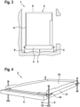
- Fig. 4 shows a rectangular cabin floor in plan view with four height-adjustable mounting feet 5 arranged in corner areas.
- the respective mounting feet 5 are arranged via spacer elements 14 on the outside of the base part 4 in its corner areas.
- the spacer elements 14 are designed as angle pieces that are attached to the vertical side wall sections 17 of the base part 4.
- the height-adjustable mounting feet are arranged outside the vertical projection of the base part 4.
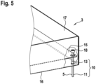
- Fig. 5 a variant is shown in which the height-adjustable mounting feet 5 are arranged within the vertical projection of the base part.
- the height-adjustable mounting feet 5 are designed and manually operable in such a way that the height adjustment can be carried out from the base part 4. In this way, the tilt (indicated by the angle of inclination ⁇ of the cabin floor relative to the horizontal) can be eliminated.
- the installer operates the left height-adjustable mounting foot marked 5'.
- the respective mounting foot 5, 5' can be moved up and down in the vertical direction for height adjustment by means of mechanical means 10, e.g. by means of a screw gear.
- the mounting foot 5 is as shown in the two embodiments according to the Figures 4 and 5 can be adjusted in height using a threaded spindle.
- the height-adjustable mounting foot 5 has a threaded rod 11 which is received in an internal thread assigned to the base part 4 and corresponding to the threaded rod. Thanks to the threaded rod 11 running in the vertical direction, the cabin floor 3 can be locally raised or lowered at the respective cabin foot and the desired height can thus be precisely set.
- the spacer elements 14 contain the internal threads in which threaded rods 11 of the mounting feet 5 are accommodated. At the lower ends of the threaded rods 11 facing the shaft floor, as Fig. 4 shows, stamp-like support elements 12 can be arranged to enlarge the support surface to the shaft floor 7. To operate the threaded spindle, the upper threaded rod end of one of the threaded rods 11 is grasped, for example by means of a tool (not shown here), and rotated as desired either clockwise or counterclockwise to adjust the height.
- the base part has internal threads integrated therein or arranged on the inside, in which the respective threaded rods 11 are received.
- a screw nut fixed to the base plate 16 with an adjoining metal sleeve has the internal thread 13.
- a screw head 18 for an Allen key is provided at the upper end of the threaded rod 11, for example.
- other engagement or actuation means for the height adjustment are also conceivable.
- the screw head shown as an example rotary handles, wing screws or toggle screws can be used as actuation means.
- the base part 4 is a flat component in a composite structure or sandwich construction.
- the base part 4 essentially consists of the base plate 16, a cover plate 15 and an intermediate composite structure core (not specifically shown).
- spirit levels can be attached to the base part, for example a circular spirit level or two tubular spirit levels arranged in a cross shape.
Landscapes
- Engineering & Computer Science (AREA)
- Civil Engineering (AREA)
- Mechanical Engineering (AREA)
- Structural Engineering (AREA)
- Cage And Drive Apparatuses For Elevators (AREA)
- Lift-Guide Devices, And Elevator Ropes And Cables (AREA)
Description
- Die Erfindung betrifft einen Kabinenboden für eine Aufzugskabine und ein Verfahren zur Montage einer Aufzugskabine.
- Aufzugsanlagen zur Beförderung von Personen und Gütern enthalten Aufzugskabinen, die in einem Aufzugsschacht auf und ab bewegbar sind. Die Aufzugskabinen können über Tragmittel, beispielsweise in Form von Tragseilen oder Tragriemen, mittels einer Antriebseinheit bewegt werden. Bei selbsttragenden Aufzugskabinen sind keine Kabinenrahmen notwendig. Zur Montage solcher Aufzugskabinen wird der Kabinenboden in die Schachtgrube gebracht. Danach können zur Fertigstellung der Aufzugskabine die Kabinenseitenwände und die Decke montiert werden. Häufig vor kommt es vor, dass der Schachtboden nicht ganz eben ist. Es besteht daher ein Bedarf, solche Bodenunebenheiten auszugleichen oder aus anderen Gründen eine Nivellierung des Kabinenbodens vorzunehmen.
- Aus der
DE 11 2014 007283 T5 , die den Oberbegriff des Anspruchs 1 offenbart, ist ein Kabinenboden für eine Aufzugskabine bekannt geworden. Der Kabinenboden ist Bestandteil einer Aufzugskabinenkomponenten-Anordnung, in welcher der Kabinenboden zum Verpacken und Transportieren zusammen mit einer Kabinendeckeneinheit in einem gestapelten Zustand untergebracht ist. Die Aufzugskabinenkomponenten-Anordnung umfasst Verbindungsglieder mit Einstell-Buchsenabschnitten, welche um 180° gedreht werden müssen. Nachdem das Verbindungsglied gedreht worden ist, verschiebt sich der Einstell-Buchsenabschnitt aus einer nach oben gerichteten Orientierung in eine nach unten gerichtete Orientierung. Der Einstell-Buchsenabschnitt umfasst einen rohrförmigen Abschnitt und einen Bolzenabschnitt, der in den rohrförmigen Abschnitt eingeführt und der aus dem rohrförmigen Abschnitt herausgezogen werden kann. Über einen Bolzenkopfabschnitt des Bolzenabschnitts kann die Position des Bolzenabschnitts so eingestellt werden, dass, wenn die Kabinenbodeneinheit auf der Schachtgrubenfläche platziert ist, die Kabinenbodeneinheit horizontal ist. - Es ist eine Aufgabe der vorliegenden Erfindung, die Nachteile des Bekannten zu vermeiden und insbesondere einen Kabinenboden zu schaffen, mit dem auf einfache und effiziente Art und Weise eine Nivellierung des Kabinenbodens vorgenommen werden kann.
- Diese und andere Aufgaben werden erfindungsgemäss mit dem Kabinenboden mit den Merkmalen des Anspruchs 1 gelöst. Der Kabinenboden für eine Aufzugskabine umfasst ein flächiges Basisteil zum Vorgeben eines Begehungsbereichs für Passagiere im Innenraum der Aufzugskabine. Dadurch, dass am Basisteil Montagefüsse angeordnet sind, wobei zum Ausrichten des Basisteils in eine horizontale Lage wenigstens einer der Montagefüsse und vorzugsweise jeder der Montagefüsse ein höhenverstellbarer Montagefuss ist, einfache und effiziente Art und Weise eine Nivellierung des Kabinenbodens vorgenommen werden. Am Basisteil können auch Montagefussaufnahmen zum Aufnehmen der Montagefüsse vorgesehen sein, so dass am Basisteil Montagefüsse anordbar sind. Über die Montagefüsse kann der Kabinenboden während einer Montagephase an einem Schachtboden eines Aufzugsschachtes der Aufzugsanlage abgestützt oder abgestellt sein. Mit dem höhenverstellbaren Montagefuss kann somit die lokale vertikale Lage des Basisteils im Bereich des jeweiligen Montagefusses eingestellt werden. Die Höhenverstellung betrifft mit anderen Worten den Abstand zwischen Basisteil und Schachtboden.
- Je nachdem in welche Richtung die Einstellung am jeweiligen höhenverstellbaren Montagefuss vorgenommen wird, kann dieser Abstand vergrössert oder verkleinert werden und somit die gewünschte Höhe eingestelllt werden.
- Die Montagefüsse können nach Beendigung der Montagephase gegebenenfalls wieder entfernt werden. Die Montagefüsse können aber auch permanent am Basisteil angeordnet sein.
- Das Basisteil ist zum Beispiel ein Bauteil in Verbundstruktur- oder Sandwich-Bauweise wie es zum Beispiel aus der
EP 1 004 538 A1 bekannt geworden ist. Das Basisteil umfasst eine Grundplatte, eine Deckplatte und einen dazwischenliegenden Verbundstruktur-Kern. Der Verbundstruktur-Kern, der die Verbindung zwischen Grund- und Deckplatte bildet, kann aus einer Vielzahl von hochkant stehenden, sich kreuzenden Lamellen in Form eines Gitterrosts aufgebaut sein, die in geeigneter Weise mit der Grund- und der Deckplatte fest verbunden sind. Selbstverständlich kann das Basisteil auch auf andere Art und Weise aufgebaut sein. Zum Beispiel könnte der Kern durch eine oder mehrere Schichten von wabenartigen Strukturen gebildet sein. Anstelle des vorgängig erwähnten bevorzugt flächigen Basisteils mit Grundplatte zum Bilden einer Unterseite und Deckplatte zum Bilden einer Oberseite sind auch andere Kabinenboden-Formen, wie etwa die in derWO 2006/026872 A2 gezeigte, von der Seite her gesehene trapezartige Formgebung, in Kombination mit den hier beschriebenen höhenverstellbaren Montagefüssen denkbar. - Zum Schaffen einer im Wesentlichen quaderförmigen Aufzugskabine kann das Basisteil in der Draufsicht eine rechteckige Form aufweisen. Vor allem in diesem Fall ist es vorteilhaft, wenn vier Montagefüsse vorgesehen sind, die in den Eckbereichen des Basisteils angeordnet sind. In den Eckbereichen des Basisteils können weiter Montagefussaufnahmen vorgesehen sein. Die Anordnung im Eckbereich erfasst dabei eine Anordnung der Montagefüsse in der Nähe oder benachbart zu den Ecken des Basisteils. Es ist somit nicht erforderlich, dass die Montagefüsse unmittelbar an der geometrischen Ecke positioniert sind. Die Montagefüsse können dabei innerhalb oder ausserhalb der vertikalen Projektion des Basisteils positioniert sein.
- Der Kabinenboden kann somit während der Montagephase über bevorzugt vier höhenverstellbare Montagefüsse am Schachtboden abgestützt sein. Alternativ zur Anordnung in den Ecken wäre es auch denkbar, die Montagefüsse mittig an den vier Rechteckseiten des Basisteils anzuordnen.
- Der jeweilige höhenverstellbare Montagefuss ist derart ausgestaltet und kann dabei bevorzugt manuell betätigbar sein, dass die Höhenverstellung vom Basisteil her erfolgen kann. Anstelle der manuellen Betätigung ist es alternativ auch denkbar, die Höhenverstellung unter Verwendung von Antrieben durchzuführen. Derart motorisch antreibbare Montagefüsse könnten auch per Fernsteuerung betätigt werden.
- Der jeweilige höhenverstellbare Montagefuss kann zur Höhenverstellung mittels mechanischen Mitteln, zum Beispiel mittels eines Schraubgetriebes, in vertikaler Richtung nach oben und unten bewegt werden. Alternativ zum Schraubgetriebe kommen auch andere mechanische Mittel, wie etwa ein Ratschenmechanismus, eine Schlittenführung, eine Kurbelvorrichtung, eine Rastvorrichtung, ein teleskopierbarer Stab oder eine Schlittenführung infrage. Anstelle von mechanischen Mitteln sind auch hydraulische oder pneumatische Mittel zur Höhenverstellung des Montagefusses denkbar.
- Der Montagefuss kann über eine Gewindespindel höhenverstellbar sein. Solche Gewindespindeln sind kostengünstig und zeichnen sich durch eine robuste und einfache Handhabung aus. Der mittels der Gewindespindel betreibbare höhenverstellbare Montagefuss kann so einfach auf die gewünschte Höhe eingestellt werden.
- Der jeweilige höhenverstellbare Montagefuss kann eine Gewindestange aufweisen, die in einem dem Basisteil zugeordneten, zur Gewindestange korrespondierenden Innengewinde zum Bilden der Gewindespindel aufgenommen oder aufnehmbar ist. Der Montagefuss kann somit als Spindelschraube ausgeführt sein. Die Gewindestange erstreckt sich, während der Montagephase und wenn sie am Basisteil angeordnet ist, vorzugsweise in vertikaler Richtung. Das Innengewinde kann die vorgängig erwähnte Montagefussaufnahme bilden.
- Seitlich am Basisteil können Abstandelemente zur Positionierung der Montagefüsse ausserhalb einer vertikalen Projektion des Basisteils befestigt oder angeformt sein. Die Abstandelemente können dabei die Innengewinde enthalten, in denen Gewindestangen der Montagefüsse aufgenommen oder aufnehmbar sind. Die Abstandelemente sind beispielsweise Winkelstücke, die an vertikalen Seitenwandabschnitten des Basisteils befestigt sind
- Aus Platzgründen kann es vorteilhaft sein, wenn die Montagefüsse innerhalb einer vertikalen Projektion des Basisteils positioniert sind. Zur Positionierung der Montagefüsse innerhalb der vertikalen Projektion des Basisteils kann das Basisteil darin intergierte Innengewinde aufweisen, in die jeweils zugehörige Gewindestangen zur Bildung der höhenverstellbaren Montagefüssen aufgenommen oder aufnehmbar sind. Das Basisteil kann hierfür innenseitige Löcher in den Eckbereichen, aufweisen, in die die Gewindestangen durchgeführt sind, wobei die Löcher zum Bilden der Gewindespindel wenigstens abschnittsweise Innengewinde aufweisen können. Die vorerwähnte Grundplatte des Basisteils kann je Montagefuss hierzu ein Loch aufweisen, in das die Gewindestangen durch- oder eingeführt ist.
- Für einen sicheren Stand kann es vorteilhaft sein, wenn an den unteren, dem Schachtboden zugewandten Enden der jeweiligen Gewindestangen stempelartig ausgebildete Auflageelemente zur Vergrösserung der Auflagefläche zum Schachtboden angeordnet sind. Diese Auflageelemente können beispielsweise über Kugellager gelenkig mit den Gewindestangen verbunden sein.
- Am oberen Ende der Gewindestangen können Eingriffs- oder Betätigungsmittel wie etwa Werkzeugaufnahmen für Schraubenzieher oder Schraubenschlüssel, Stellschrauben mit getrennten Drehgriffen, Flügelschrauben oder Knebelschrauben angeordnet sein, wodurch die manuelle Betätigung der Gewindespindel zur Höhenverstellung des Montagefusses vereinfacht wird.
- Sodann kann es vorteilhaft sein, wenn zum Sichern der Höheneinstellung an der Gewindestange jeweils eine Kontermutter angebracht ist.
- Vorteilhaft kann es weiter sein, wenn zur Überprüfung der horizontalen Lage wenigstens eine Libelle an das Basisteil befestigt ist. Die Libelle kann dabei wenigstens temporär oder permanent am Basisteil befestigt sein. Die Libelle kann eine Dosenlibelle oder eine Röhrenlibelle sein. Die Libelle kann mittels einer Klebeverbindung am Basisteil befestigt sein. Bei Verwendung von Röhrenlibellen kann es vorteilhaft sein, wenn die Röhrenlibellen kreuzförmig zueinander angeordnet sind.
- Ein weiterer Aspekt der Erfindung betrifft ein Verfahren zur Montage einer Aufzugskabine in einem Aufzugsschacht einer Aufzugsanlage gemäss Anspruch 9. Das Verfahren umfasst dabei folgende Schritte: (i) Einbringen eines Kabinenbodens, insbesondere des vorgängig beschriebenen Kabinenbodens, in den Aufzugsschacht, wobei der Kabinenboden auf dem Schachtboden abgesetzt wird; (ii) Nivellieren des über Montagefüsse auf dem Schachtboden stehenden Kabinenbodens, indem wenigstens ein am Kabinenboden angeordneter, höhenverstellbarer Montagefuss zur Höhenverstellung betätigt wird; und (iii) Anbau der Kabinenseitenwände und bevorzugt nachfolgend des Kabinendachs an den so nivellierten Kabinenboden.
- Weitere Einzelmerkmale und Vorteile der Erfindung ergeben sich aus der nachfolgenden Beschreibung von Ausführungsbeispielen und aus den Zeichnungen. Es zeigen:
- Fig. 1
- eine stark vereinfachte Darstellung eines Aufzugsschachtes mit einem auf den Schachtboden abgestellten Kabinenboden,
- Fig. 2
- der Kabinenboden nach einem Nivellierungsvorgang,
- Fig. 3
- der Kabinenboden mit daran angebauten Kabinenseitenwänden,
- Fig. 4
- eine perspektivische Darstellung eines erfindungsgemässen Aufzugskabinenbodens, und
- Fig. 5
- eine perspektivische Teilansicht auf einen Eckbereich eines Kabinenbodens gemäss einem alternativen Ausführungsbeispiel.
-
Fig. 1 zeigt einen unteren Bereich eines Aufzugsschachtes für eine insgesamt mit 1 bezeichnete Aufzugsanlage. Vorliegend weist die Aufzugsanlage 1 einen Aufzugsschacht mit einer geringen Grubentiefe auf. Auf dem Schachtboden des Aufzugsschachtes befindet sich ein mit 3 bezeichneter Kabinenboden. Der Kabinenboden besteht aus einem Basisteil 4, das einen Begehungsbereich für Passagiere vorgibt, und aus Montagefüssen 5, über die der Kabinenboden 3 auf dem Schachtboden abgestützt ist. - Zur Fertigung des Aufzugsschachtes wird häufig Beton eingesetzt. Es ist schwierig, den Schachtboden mit einer planen und horizontalen Oberfläche anzufertigen. Deshalb kann nach erstmaligem Absetzen der Kabinenboden sich in einer leichten Schieflage befinden. Dank höhenverstellbarer Montagefüsse 5 kann diese Schieflage behoben werden. Hierzu wird, wie beispielhaft in
Fig. 2 gezeigt ist, der höhenverstellbare Montagefuss 5 in der Höhe verstellt, bis das Basisteil in die gewünschte horizontale Lage gebracht wird. Nachdem das Basisteil 4 ausgerichtet ist, kann die Montage der Aufzugskabine weitergeführt werden. Die Kabinenseitenwände 8 können nun an den so nivellierten Kabinenboden 3 gebaut werden. Nach dem Anbau der Kabinenseitenwände 8 kann schliesslich das mit strichlierten Linien angedeutete Kabinendach 9 auf die Kabinenseitenwände 8 angebracht werden. -
Fig. 4 zeigt einen in der Draufsicht eine rechteckigen Kabinenboden mit vier in Eckbereichen angeordneten höhenverstellbaren Montagefüssen 5. Die jeweiligen Montagefüsse 5 sind über Abstandselemente 14 aussenseitig am Basisteil 4 in seinen Eckbereichen angeordnet. Die Abstandselemente 14 sind vorliegend als Winkelstücke ausgeführt, die an den vertikalen Seitenwandabschnitten 17 des Basisteils 4 befestigt sind. Im Ausführungsbeispiel gemässFig. 4 sind die höhenverstellbaren Montagefüsse ausserhalb der vertikalen Projektion des Basisteils 4 angeordnet. InFig. 5 ist eine Variante gezeigt, bei der die höhenverstellbaren Montagefüsse 5 innerhalb der vertikalen Projektion des Basisteils angeordnet sind. - Die höhenverstellbaren Montagefüsse 5 sind derart ausgestaltet und manuell betätigbar, dass die Höhenverstellung vom Basisteil 4 her erfolgen kann. So kann die Schieflage (angedeutet durch den Neigungswinkel α des Kabinenbodens gegenüber der Horizontalen) aufgehoben werden. Im in
Fig. 2 gezeigten Beispiel betätigt der Monteur die mit 5' bezeichnete linke höhenverstellbare Montagefuss. Der jeweilige Montagefuss 5, 5' ist zur Höhenverstellung mittels mechanischen Mitteln 10 z.B. mittels eines Schraubgetriebes in vertikaler Richtung noch oben und unten bewegbar. - Der Montagefuss 5 ist wie aus den beiden Ausführungsbeispielen gemäss der
Figuren 4 und5 hervorgeht, über eine Gewindespindel höhenverstellbar ist. Der höhenverstellbare Montagefuss 5 weist eine Gewindestange 11 auf, die in einem dem Basisteil 4 zugeordneten, zur Gewindestange korrespondierenden Innengewinde aufgenommen ist. Dank der in vertikaler Richtung verlaufenden Gewindestange 11 kann der Kabinenboden 3 beim jeweiligen Kabinenfuss örtlich gehoben oder abgesenkt und so präzise die gewünschte Höhe eingestellt werden. - Im Ausführungsbeispiel gemäss
Fig. 4 enthalten die Abstandelemente 14 die Innengewinde, in denen Gewindestangen 11 der Montagefüsse 5 aufgenommen sind. An unteren, dem Schachtboden zugewandten Enden der Gewindestangen 11 können, wieFig. 4 zeigt, stempelartig ausgebildete Auflageelemente 12 zur Vergrösserung der Auflagefläche zum Schachtboden 7 angeordnet sein. Zum Betätigen der Gewindespindel wird zum Beispiel mittels eines (hier nicht dargestellten) Werkzeuges das obere Gewindestangen-Ende einer der Gewindestangen 11 erfasst und wunschgemäss entweder im Uhrzeiger- oder im Gegenurzeigersinn zur Höhenverstellung gedreht. - Im Ausführungsbeispiel gemäss
Fig. 5 weist das Basisteil darin integrierte bzw. innenseitig angeordnete Innengewinde auf, in die die jeweiligem Gewindestangen 11 aufgenommen sind. Im vorliegenden Ausführungsbeispiel weist eine an der Grundplatte 16 fixierte Schraubenmutter mit daran anschliessender Metallhülse das Innengewinde 13 auf. Am oberen Ende der Gewindestange 11 ist beispielhaft ein Schraubenkopf 18 für einen Imbusschlüssel vorgesehen. Selbstverständlich auch andere Eingriffs- oder Betätigungsmittel für die Höhenverstellung denkbar. Zum Beispiel kommen anstelle des bespielhaft gezeigten Schraubenkopfes Drehgriffe, Flügelschrauben oder Knebelschrauben als Betätigungsmittel in Frage. - Aus
Fig. 5 ist entnehmbar, dass das Basisteil 4 ein flächiges Bauteil in Verbundstruktur- oder Sandwich-Bauweise ist. Das Basisteil 4 besteht im Wesentlichen aus der Grundplatte 16, einer Deckplatte 15 und einem dazwischenliegenden (nicht spezifisch dargestellten) Verbundstruktur-Kern. - Zur Überprüfung der horizontalen Lage können am Basisteil (nicht dargestellte) Libellen, zum Beispiel eine Dosenlibelle oder zwei kreuzförmig zueinander angeordnete Röhrenlibellen befestigt sein.
Claims (9)
- Kabinenboden (3) für eine Aufzugskabine (2) mit einem Basisteil (4), wobei am Basisteil (4) Montagefüsse (5), über die der Kabinenboden während einer Montagephase an einem Schachtboden eines Aufzugsschachtes der Aufzugsanlage abstützbar oder abstellbar ist, angeordnet sind, wobei zum Ausrichten des Basisteils (4) in eine horizontale Lage wenigstens einer der Montagefüsse (5) und vorzugsweise jeder der Montagefüsse (5) ein höhenverstellbarer Montagefuss ist, wobei das Basisteil (4) ein flächiges Basisteil zum Vorgeben eines Begehungsbereichs für Passagiere im Innenraum der Aufzugskabine ist, dadurch gekennzeichnet, dass der jeweilige höhenverstellbare Montagefuss (5) derart ausgestaltet ist, dass die Höhenverstellung vom flächigen Basisteil (4) her erfolgen kann.
- Kabinenboden nach Anspruch 1, dadurch gekennzeichnet, dass das Basisteil (4) zum Schaffen von im Wesentlichen quaderförmigen Aufzugskabinen (2) in der Draufsicht eine rechteckige Form aufweist und dass vier vorzugsweise in den Eckbereichen des Basisteils (4) angeordnete Montagefüsse (5) vorgesehen sind.
- Kabinenboden nach Anspruch 1 oder 2, dadurch gekennzeichnet, dass der Montagefuss (5) über eine Gewindespindel (10) höhenverstellbar ist.
- Kabinenboden nach einem der Ansprüche 1 bis 3, dadurch gekennzeichnet, dass der jeweilige höhenverstellbare Montagefuss (5) eine Gewindestange (11) aufweist.
- Kabinenboden nach einem der Ansprüche 1 bis 4, dadurch gekennzeichnet, dass seitlich am Basisteil (4) Abstandelemente (14) zur Positionierung der Montagefüsse (5) ausserhalb einer vertikalen Projektion des Basisteils befestigt oder angeformt sind.
- Kabinenboden nach einem der Ansprüche 1 bis 4, dadurch gekennzeichnet, dass zur Positionierung der Montagefüsse (5) innerhalb einer vertikalen Projektion des Basisteils das Basisteil (4) Innengewinde (13) aufweist, in die jeweils zugehörige Gewindestangen (11) zur Bildung der höhenverstellbaren Montagefüssen (5) aufgenommen oder aufnehmbar sind.
- Kabinenboden nach einem der Ansprüche 1 bis 6, dadurch gekennzeichnet, dass an unteren, dem Schachtboden zugewandten Enden der Montagefüsse und insbesondere an unteren, dem Schachtboden zugewandten Enden der jeweiligen Gewindestangen (11) stempelartig ausgebildete Auflageelemente (12) zur Vergrösserung der Auflagefläche zum Schachtboden angeordnet sind.
- Kabinenboden nach einem der Ansprüche 1 bis 7, dadurch gekennzeichnet, dass zur Überprüfung der horizontalen Lage wenigstens eine Libelle permanent oder wenigstens temporär für die Montagephase am Basisteil (4) befestigt ist.
- Verfahren zur Montage einer Aufzugskabine (2) in einem Aufzugsschacht einer Aufzugsanlage (1), umfassend:- Einbringen eines Kabinenbodens (3) in den Aufzugsschacht, wobei der Kabinenboden (3) auf dem Schachtboden abgesetzt wird, wobei der Kabinenboden (3) ein flächiges Basisteil (4) zum Vorgeben eines Begehungsbereichs für Passagiere im Innenraum der Aufzugskabine umfasst,- Nivellieren des über Montagefüsse (5) auf dem Schachtboden stehenden Kabinenbodens (3), indem wenigstens ein höhenverstellbarer Montagefuss (5) betätigt wird und die Höhenverstellung vom flächigen Basisteil (4) her erfolgt,- Anbau der Kabinenseitenwände (8) an den Kabinenboden (3).
Applications Claiming Priority (2)
| Application Number | Priority Date | Filing Date | Title |
|---|---|---|---|
| EP20210527 | 2020-11-30 | ||
| PCT/EP2021/082600 WO2022112211A1 (de) | 2020-11-30 | 2021-11-23 | Kabinenboden für eine aufzugskabine und verfahren zur montage einer aufzugskabine |
Publications (2)
| Publication Number | Publication Date |
|---|---|
| EP4251552A1 EP4251552A1 (de) | 2023-10-04 |
| EP4251552B1 true EP4251552B1 (de) | 2024-10-02 |
Family
ID=73646111
Family Applications (1)
| Application Number | Title | Priority Date | Filing Date |
|---|---|---|---|
| EP21816431.7A Active EP4251552B1 (de) | 2020-11-30 | 2021-11-23 | Kabinenboden für eine aufzugskabine und verfahren zur montage einer aufzugskabine |
Country Status (7)
| Country | Link |
|---|---|
| US (1) | US12103820B2 (de) |
| EP (1) | EP4251552B1 (de) |
| JP (1) | JP2023553844A (de) |
| KR (1) | KR20230111204A (de) |
| CN (1) | CN116568626B (de) |
| ES (1) | ES2994220T3 (de) |
| WO (1) | WO2022112211A1 (de) |
Family Cites Families (22)
| Publication number | Priority date | Publication date | Assignee | Title |
|---|---|---|---|---|
| JPS5435365B2 (de) * | 1974-02-25 | 1979-11-02 | ||
| JPS63272854A (ja) * | 1987-04-30 | 1988-11-10 | ナカ工業株式会社 | フロアパネル支持装置 |
| JPH07327762A (ja) * | 1994-06-07 | 1995-12-19 | Hakko Hatsujo Seisakusho:Kk | 家具の高さ調節装置 |
| JPH08158604A (ja) * | 1994-12-06 | 1996-06-18 | Nitto Kogyo Kk | 二重床用固定脚 |
| JPH09287696A (ja) * | 1996-04-19 | 1997-11-04 | Fuji Xerox Co Ltd | アジャスタ |
| JPH09309679A (ja) * | 1996-05-21 | 1997-12-02 | Toshiba Elevator Eng Kk | エレベータのかご室 |
| FI109291B (fi) * | 1997-03-07 | 2002-06-28 | Kone Corp | Menetelmä ja laitteisto hissin asentamiseksi |
| JPH11246148A (ja) * | 1998-03-02 | 1999-09-14 | Hitachi Building Systems Co Ltd | エレベータ乗かご据付装置 |
| MY121825A (en) | 1998-11-24 | 2006-02-28 | Inventio Ag | Highly rigid elevator car floor |
| JP5085325B2 (ja) | 2004-09-09 | 2012-11-28 | インベンテイオ・アクテイエンゲゼルシヤフト | モジュールエレベータケージ |
| JP4867470B2 (ja) * | 2006-05-22 | 2012-02-01 | 三菱電機株式会社 | エレベータのかご床装置 |
| DE102007025545A1 (de) * | 2007-05-31 | 2008-12-04 | TÜV Rheinland Industrie Service GmbH | Kompensationseinrichtung |
| CN102060222A (zh) * | 2011-01-04 | 2011-05-18 | 张向阳 | 一种采用组合式井架组装的电梯 |
| JP2013166616A (ja) * | 2012-02-15 | 2013-08-29 | Mitsubishi Electric Corp | エレベーター |
| CN105555698A (zh) * | 2013-09-27 | 2016-05-04 | 三菱电机株式会社 | 电梯的轿厢 |
| CN103979385B (zh) * | 2014-05-30 | 2016-06-29 | 湖南海诺电梯有限公司 | 一种浅底坑电梯新型轿厢结构 |
| JP6223602B2 (ja) * | 2014-12-25 | 2017-11-01 | 三菱電機株式会社 | エレベータかご用部品の組立体、かご製造方法、及びエレベータのかご |
| US11180346B2 (en) * | 2015-10-12 | 2021-11-23 | Inventio Ag | Car for an elevator in an elevator shaft |
| CN106006319A (zh) * | 2016-07-29 | 2016-10-12 | 上海汉神机电股份有限公司 | 可变角度倾斜机构 |
| DE102016217016A1 (de) * | 2016-09-07 | 2018-03-08 | Thyssenkrupp Ag | Fahrkorb für eine Aufzugsanlage mit Linearmotorantrieb, Aufzugsanlage mit einem solchen Fahrkorb und Verfahren zum Betreiben einer Aufzugsanlage |
| CN211198292U (zh) * | 2019-11-25 | 2020-08-07 | 北京杏林伟业电梯工程有限公司 | 一种电梯轿厢调平装置 |
| CN114436079B (zh) * | 2022-01-24 | 2023-07-21 | 日立电梯(上海)有限公司 | 一种保持电梯平层精度的装置及方法 |
-
2021
- 2021-11-23 US US18/253,942 patent/US12103820B2/en active Active
- 2021-11-23 WO PCT/EP2021/082600 patent/WO2022112211A1/de not_active Ceased
- 2021-11-23 JP JP2023532730A patent/JP2023553844A/ja active Pending
- 2021-11-23 CN CN202180079811.3A patent/CN116568626B/zh active Active
- 2021-11-23 ES ES21816431T patent/ES2994220T3/es active Active
- 2021-11-23 EP EP21816431.7A patent/EP4251552B1/de active Active
- 2021-11-23 KR KR1020237018064A patent/KR20230111204A/ko active Pending
Also Published As
| Publication number | Publication date |
|---|---|
| US12103820B2 (en) | 2024-10-01 |
| WO2022112211A1 (de) | 2022-06-02 |
| ES2994220T3 (en) | 2025-01-20 |
| JP2023553844A (ja) | 2023-12-26 |
| US20240010466A1 (en) | 2024-01-11 |
| CN116568626A (zh) | 2023-08-08 |
| KR20230111204A (ko) | 2023-07-25 |
| CN116568626B (zh) | 2026-03-20 |
| EP4251552A1 (de) | 2023-10-04 |
Similar Documents
| Publication | Publication Date | Title |
|---|---|---|
| DE3935665C2 (de) | Vorrichtung zum Transportieren eines Bauteils | |
| EP4209655B1 (de) | Modulare tunnelschalungsvorrichtung | |
| DE60315022T2 (de) | Sicherheitsumzäunung auf aufzugskabine | |
| EP3743567B1 (de) | Variables containersystem | |
| EP2593333B1 (de) | Fahrzeug in modularer bauweise | |
| DE112014007283T5 (de) | Aufzugkabinenkomponenten-anordnung, kabinenherstellungsverfahren und aufzugskabine | |
| DE4033492C2 (de) | Verfahrbare Vorrichtung zur Erleichterung des Mauerwandbaus | |
| DE69504969T2 (de) | Verfahren und vorrichtung zum tranferieren von modulen | |
| EP2044916B2 (de) | Trittplattenvorrichtung | |
| DE102007021159B4 (de) | Rostdeckenschalung zur Einbindung einer Säule | |
| EP3963140B1 (de) | Montagegestell zur montage einer bodenebenen duschtasse | |
| DE102018122634B4 (de) | Ladungs-Sicherungs-System sowie Fahrzeug umfassend ein solches System und ein Verfahren zur Ladungs-Sicherung | |
| EP3381858B1 (de) | Aus einem bausatz gebildeter temporärer aufzug | |
| DE3720239C2 (de) | ||
| EP4251552A1 (de) | Kabinenboden für eine aufzugskabine und verfahren zur montage einer aufzugskabine | |
| EP4490092B1 (de) | Personenförderanlage mit einer stütze | |
| EP4540163B1 (de) | Schachtmodul zur bildung eines aus aufeinandergesetzten schachtmodulen zusammengesetzten aufzugschachts für eine aufzuganlage | |
| DE202025107449U1 (de) | Hubvorrichtung für Fundamente | |
| DE20216236U1 (de) | Sockel für Geldautomaten | |
| DE102008048608A1 (de) | Bodenkonstruktion für Schienenfahrzeuge | |
| WO2022136118A1 (de) | Aufzugskabine für eine aufzugsanlage und installationsverfahren zum installieren einer aufzugsanlage | |
| DE202004006798U1 (de) | Fußbodenkassette eines modularen Zeltbodens und Gerüstkonstruktion eines Zeltes | |
| WO2019161915A1 (de) | Flächenportal | |
| EP4673390A1 (de) | Verfahren zur installation einer aufzuganlage | |
| DE102022100338A1 (de) | Ausgleichsvorrichtung |
Legal Events
| Date | Code | Title | Description |
|---|---|---|---|
| STAA | Information on the status of an ep patent application or granted ep patent |
Free format text: STATUS: UNKNOWN |
|
| STAA | Information on the status of an ep patent application or granted ep patent |
Free format text: STATUS: THE INTERNATIONAL PUBLICATION HAS BEEN MADE |
|
| PUAI | Public reference made under article 153(3) epc to a published international application that has entered the european phase |
Free format text: ORIGINAL CODE: 0009012 |
|
| STAA | Information on the status of an ep patent application or granted ep patent |
Free format text: STATUS: REQUEST FOR EXAMINATION WAS MADE |
|
| 17P | Request for examination filed |
Effective date: 20230502 |
|
| AK | Designated contracting states |
Kind code of ref document: A1 Designated state(s): AL AT BE BG CH CY CZ DE DK EE ES FI FR GB GR HR HU IE IS IT LI LT LU LV MC MK MT NL NO PL PT RO RS SE SI SK SM TR |
|
| DAV | Request for validation of the european patent (deleted) | ||
| DAX | Request for extension of the european patent (deleted) | ||
| GRAP | Despatch of communication of intention to grant a patent |
Free format text: ORIGINAL CODE: EPIDOSNIGR1 |
|
| STAA | Information on the status of an ep patent application or granted ep patent |
Free format text: STATUS: GRANT OF PATENT IS INTENDED |
|
| INTG | Intention to grant announced |
Effective date: 20240605 |
|
| GRAS | Grant fee paid |
Free format text: ORIGINAL CODE: EPIDOSNIGR3 |
|
| GRAA | (expected) grant |
Free format text: ORIGINAL CODE: 0009210 |
|
| STAA | Information on the status of an ep patent application or granted ep patent |
Free format text: STATUS: THE PATENT HAS BEEN GRANTED |
|
| AK | Designated contracting states |
Kind code of ref document: B1 Designated state(s): AL AT BE BG CH CY CZ DE DK EE ES FI FR GB GR HR HU IE IS IT LI LT LU LV MC MK MT NL NO PL PT RO RS SE SI SK SM TR |
|
| REG | Reference to a national code |
Ref country code: GB Ref legal event code: FG4D Free format text: NOT ENGLISH |
|
| REG | Reference to a national code |
Ref country code: CH Ref legal event code: EP |
|
| REG | Reference to a national code |
Ref country code: DE Ref legal event code: R096 Ref document number: 502021005362 Country of ref document: DE |
|
| REG | Reference to a national code |
Ref country code: IE Ref legal event code: FG4D Free format text: LANGUAGE OF EP DOCUMENT: GERMAN |
|
| REG | Reference to a national code |
Ref country code: ES Ref legal event code: FG2A Ref document number: 2994220 Country of ref document: ES Kind code of ref document: T3 Effective date: 20250120 |
|
| REG | Reference to a national code |
Ref country code: LT Ref legal event code: MG9D |
|
| REG | Reference to a national code |
Ref country code: NL Ref legal event code: MP Effective date: 20241002 |
|
| PG25 | Lapsed in a contracting state [announced via postgrant information from national office to epo] |
Ref country code: NL Free format text: LAPSE BECAUSE OF FAILURE TO SUBMIT A TRANSLATION OF THE DESCRIPTION OR TO PAY THE FEE WITHIN THE PRESCRIBED TIME-LIMIT Effective date: 20241002 |
|
| PG25 | Lapsed in a contracting state [announced via postgrant information from national office to epo] |
Ref country code: NL Free format text: LAPSE BECAUSE OF FAILURE TO SUBMIT A TRANSLATION OF THE DESCRIPTION OR TO PAY THE FEE WITHIN THE PRESCRIBED TIME-LIMIT Effective date: 20241002 |
|
| PG25 | Lapsed in a contracting state [announced via postgrant information from national office to epo] |
Ref country code: HR Free format text: LAPSE BECAUSE OF FAILURE TO SUBMIT A TRANSLATION OF THE DESCRIPTION OR TO PAY THE FEE WITHIN THE PRESCRIBED TIME-LIMIT Effective date: 20241002 Ref country code: PT Free format text: LAPSE BECAUSE OF FAILURE TO SUBMIT A TRANSLATION OF THE DESCRIPTION OR TO PAY THE FEE WITHIN THE PRESCRIBED TIME-LIMIT Effective date: 20250203 Ref country code: IS Free format text: LAPSE BECAUSE OF FAILURE TO SUBMIT A TRANSLATION OF THE DESCRIPTION OR TO PAY THE FEE WITHIN THE PRESCRIBED TIME-LIMIT Effective date: 20250202 |
|
| PG25 | Lapsed in a contracting state [announced via postgrant information from national office to epo] |
Ref country code: FI Free format text: LAPSE BECAUSE OF FAILURE TO SUBMIT A TRANSLATION OF THE DESCRIPTION OR TO PAY THE FEE WITHIN THE PRESCRIBED TIME-LIMIT Effective date: 20241002 |
|
| PG25 | Lapsed in a contracting state [announced via postgrant information from national office to epo] |
Ref country code: BG Free format text: LAPSE BECAUSE OF FAILURE TO SUBMIT A TRANSLATION OF THE DESCRIPTION OR TO PAY THE FEE WITHIN THE PRESCRIBED TIME-LIMIT Effective date: 20241002 |
|
| PG25 | Lapsed in a contracting state [announced via postgrant information from national office to epo] |
Ref country code: NO Free format text: LAPSE BECAUSE OF FAILURE TO SUBMIT A TRANSLATION OF THE DESCRIPTION OR TO PAY THE FEE WITHIN THE PRESCRIBED TIME-LIMIT Effective date: 20250102 |
|
| PG25 | Lapsed in a contracting state [announced via postgrant information from national office to epo] |
Ref country code: LV Free format text: LAPSE BECAUSE OF FAILURE TO SUBMIT A TRANSLATION OF THE DESCRIPTION OR TO PAY THE FEE WITHIN THE PRESCRIBED TIME-LIMIT Effective date: 20241002 Ref country code: GR Free format text: LAPSE BECAUSE OF FAILURE TO SUBMIT A TRANSLATION OF THE DESCRIPTION OR TO PAY THE FEE WITHIN THE PRESCRIBED TIME-LIMIT Effective date: 20250103 |
|
| PG25 | Lapsed in a contracting state [announced via postgrant information from national office to epo] |
Ref country code: CZ Free format text: LAPSE BECAUSE OF FAILURE TO SUBMIT A TRANSLATION OF THE DESCRIPTION OR TO PAY THE FEE WITHIN THE PRESCRIBED TIME-LIMIT Effective date: 20241002 Ref country code: PL Free format text: LAPSE BECAUSE OF FAILURE TO SUBMIT A TRANSLATION OF THE DESCRIPTION OR TO PAY THE FEE WITHIN THE PRESCRIBED TIME-LIMIT Effective date: 20241002 |
|
| PG25 | Lapsed in a contracting state [announced via postgrant information from national office to epo] |
Ref country code: RS Free format text: LAPSE BECAUSE OF FAILURE TO SUBMIT A TRANSLATION OF THE DESCRIPTION OR TO PAY THE FEE WITHIN THE PRESCRIBED TIME-LIMIT Effective date: 20250102 |
|
| PG25 | Lapsed in a contracting state [announced via postgrant information from national office to epo] |
Ref country code: SM Free format text: LAPSE BECAUSE OF FAILURE TO SUBMIT A TRANSLATION OF THE DESCRIPTION OR TO PAY THE FEE WITHIN THE PRESCRIBED TIME-LIMIT Effective date: 20241002 |
|
| REG | Reference to a national code |
Ref country code: DE Ref legal event code: R097 Ref document number: 502021005362 Country of ref document: DE |
|
| PG25 | Lapsed in a contracting state [announced via postgrant information from national office to epo] |
Ref country code: MC Free format text: LAPSE BECAUSE OF FAILURE TO SUBMIT A TRANSLATION OF THE DESCRIPTION OR TO PAY THE FEE WITHIN THE PRESCRIBED TIME-LIMIT Effective date: 20241002 |
|
| PG25 | Lapsed in a contracting state [announced via postgrant information from national office to epo] |
Ref country code: DK Free format text: LAPSE BECAUSE OF FAILURE TO SUBMIT A TRANSLATION OF THE DESCRIPTION OR TO PAY THE FEE WITHIN THE PRESCRIBED TIME-LIMIT Effective date: 20241002 |
|
| PG25 | Lapsed in a contracting state [announced via postgrant information from national office to epo] |
Ref country code: LU Free format text: LAPSE BECAUSE OF NON-PAYMENT OF DUE FEES Effective date: 20241123 |
|
| PG25 | Lapsed in a contracting state [announced via postgrant information from national office to epo] |
Ref country code: EE Free format text: LAPSE BECAUSE OF FAILURE TO SUBMIT A TRANSLATION OF THE DESCRIPTION OR TO PAY THE FEE WITHIN THE PRESCRIBED TIME-LIMIT Effective date: 20241002 |
|
| PG25 | Lapsed in a contracting state [announced via postgrant information from national office to epo] |
Ref country code: RO Free format text: LAPSE BECAUSE OF FAILURE TO SUBMIT A TRANSLATION OF THE DESCRIPTION OR TO PAY THE FEE WITHIN THE PRESCRIBED TIME-LIMIT Effective date: 20241002 |
|
| PG25 | Lapsed in a contracting state [announced via postgrant information from national office to epo] |
Ref country code: SK Free format text: LAPSE BECAUSE OF FAILURE TO SUBMIT A TRANSLATION OF THE DESCRIPTION OR TO PAY THE FEE WITHIN THE PRESCRIBED TIME-LIMIT Effective date: 20241002 |
|
| PLBE | No opposition filed within time limit |
Free format text: ORIGINAL CODE: 0009261 |
|
| STAA | Information on the status of an ep patent application or granted ep patent |
Free format text: STATUS: NO OPPOSITION FILED WITHIN TIME LIMIT |
|
| REG | Reference to a national code |
Ref country code: BE Ref legal event code: MM Effective date: 20241130 |
|
| PG25 | Lapsed in a contracting state [announced via postgrant information from national office to epo] |
Ref country code: SE Free format text: LAPSE BECAUSE OF FAILURE TO SUBMIT A TRANSLATION OF THE DESCRIPTION OR TO PAY THE FEE WITHIN THE PRESCRIBED TIME-LIMIT Effective date: 20241002 |
|
| 26N | No opposition filed |
Effective date: 20250703 |
|
| PG25 | Lapsed in a contracting state [announced via postgrant information from national office to epo] |
Ref country code: BE Free format text: LAPSE BECAUSE OF NON-PAYMENT OF DUE FEES Effective date: 20241130 |
|
| PG25 | Lapsed in a contracting state [announced via postgrant information from national office to epo] |
Ref country code: IE Free format text: LAPSE BECAUSE OF NON-PAYMENT OF DUE FEES Effective date: 20241123 |
|
| REG | Reference to a national code |
Ref country code: CH Ref legal event code: U11 Free format text: ST27 STATUS EVENT CODE: U-0-0-U10-U11 (AS PROVIDED BY THE NATIONAL OFFICE) Effective date: 20251201 |
|
| PGFP | Annual fee paid to national office [announced via postgrant information from national office to epo] |
Ref country code: DE Payment date: 20251126 Year of fee payment: 5 |
|
| PGFP | Annual fee paid to national office [announced via postgrant information from national office to epo] |
Ref country code: GB Payment date: 20251125 Year of fee payment: 5 |
|
| PGFP | Annual fee paid to national office [announced via postgrant information from national office to epo] |
Ref country code: AT Payment date: 20260113 Year of fee payment: 5 |
|
| PGFP | Annual fee paid to national office [announced via postgrant information from national office to epo] |
Ref country code: IT Payment date: 20251121 Year of fee payment: 5 |
|
| PGFP | Annual fee paid to national office [announced via postgrant information from national office to epo] |
Ref country code: FR Payment date: 20251124 Year of fee payment: 5 |
|
| PGFP | Annual fee paid to national office [announced via postgrant information from national office to epo] |
Ref country code: CH Payment date: 20251201 Year of fee payment: 5 |
|
| PGFP | Annual fee paid to national office [announced via postgrant information from national office to epo] |
Ref country code: ES Payment date: 20251209 Year of fee payment: 5 |
|
| PG25 | Lapsed in a contracting state [announced via postgrant information from national office to epo] |
Ref country code: HU Free format text: LAPSE BECAUSE OF FAILURE TO SUBMIT A TRANSLATION OF THE DESCRIPTION OR TO PAY THE FEE WITHIN THE PRESCRIBED TIME-LIMIT; INVALID AB INITIO Effective date: 20211123 |
|
| PG25 | Lapsed in a contracting state [announced via postgrant information from national office to epo] |
Ref country code: CY Free format text: LAPSE BECAUSE OF FAILURE TO SUBMIT A TRANSLATION OF THE DESCRIPTION OR TO PAY THE FEE WITHIN THE PRESCRIBED TIME-LIMIT; INVALID AB INITIO Effective date: 20211123 |