EP4092673B1 - Leseverstärker, speicher und steuerverfahren - Google Patents
Leseverstärker, speicher und steuerverfahren Download PDFInfo
- Publication number
- EP4092673B1 EP4092673B1 EP21859351.5A EP21859351A EP4092673B1 EP 4092673 B1 EP4092673 B1 EP 4092673B1 EP 21859351 A EP21859351 A EP 21859351A EP 4092673 B1 EP4092673 B1 EP 4092673B1
- Authority
- EP
- European Patent Office
- Prior art keywords
- terminal
- transistor
- bit line
- voltage
- power supply
- Prior art date
- Legal status (The legal status is an assumption and is not a legal conclusion. Google has not performed a legal analysis and makes no representation as to the accuracy of the status listed.)
- Active
Links
Images


Classifications
-
- G—PHYSICS
- G11—INFORMATION STORAGE
- G11C—STATIC STORES
- G11C7/00—Arrangements for writing information into, or reading information out from, a digital store
- G11C7/06—Sense amplifiers; Associated circuits, e.g. timing or triggering circuits
-
- G—PHYSICS
- G11—INFORMATION STORAGE
- G11C—STATIC STORES
- G11C7/00—Arrangements for writing information into, or reading information out from, a digital store
- G11C7/06—Sense amplifiers; Associated circuits, e.g. timing or triggering circuits
- G11C7/08—Control thereof
-
- G—PHYSICS
- G11—INFORMATION STORAGE
- G11C—STATIC STORES
- G11C7/00—Arrangements for writing information into, or reading information out from, a digital store
- G11C7/06—Sense amplifiers; Associated circuits, e.g. timing or triggering circuits
- G11C7/062—Differential amplifiers of non-latching type, e.g. comparators, long-tailed pairs
-
- G—PHYSICS
- G11—INFORMATION STORAGE
- G11C—STATIC STORES
- G11C11/00—Digital stores characterised by the use of particular electric or magnetic storage elements; Storage elements therefor
- G11C11/21—Digital stores characterised by the use of particular electric or magnetic storage elements; Storage elements therefor using electric elements
- G11C11/34—Digital stores characterised by the use of particular electric or magnetic storage elements; Storage elements therefor using electric elements using semiconductor devices
- G11C11/40—Digital stores characterised by the use of particular electric or magnetic storage elements; Storage elements therefor using electric elements using semiconductor devices using transistors
- G11C11/401—Digital stores characterised by the use of particular electric or magnetic storage elements; Storage elements therefor using electric elements using semiconductor devices using transistors forming cells needing refreshing or charge regeneration, i.e. dynamic cells
- G11C11/4063—Auxiliary circuits, e.g. for addressing, decoding, driving, writing, sensing or timing
- G11C11/407—Auxiliary circuits, e.g. for addressing, decoding, driving, writing, sensing or timing for memory cells of the field-effect type
- G11C11/4074—Power supply or voltage generation circuits, e.g. bias voltage generators, substrate voltage generators, back-up power, power control circuits
-
- G—PHYSICS
- G11—INFORMATION STORAGE
- G11C—STATIC STORES
- G11C11/00—Digital stores characterised by the use of particular electric or magnetic storage elements; Storage elements therefor
- G11C11/21—Digital stores characterised by the use of particular electric or magnetic storage elements; Storage elements therefor using electric elements
- G11C11/34—Digital stores characterised by the use of particular electric or magnetic storage elements; Storage elements therefor using electric elements using semiconductor devices
- G11C11/40—Digital stores characterised by the use of particular electric or magnetic storage elements; Storage elements therefor using electric elements using semiconductor devices using transistors
- G11C11/401—Digital stores characterised by the use of particular electric or magnetic storage elements; Storage elements therefor using electric elements using semiconductor devices using transistors forming cells needing refreshing or charge regeneration, i.e. dynamic cells
- G11C11/4063—Auxiliary circuits, e.g. for addressing, decoding, driving, writing, sensing or timing
- G11C11/407—Auxiliary circuits, e.g. for addressing, decoding, driving, writing, sensing or timing for memory cells of the field-effect type
- G11C11/409—Read-write [R-W] circuits
- G11C11/4091—Sense or sense/refresh amplifiers, or associated sense circuitry, e.g. for coupled bit-line precharging, equalising or isolating
-
- G—PHYSICS
- G11—INFORMATION STORAGE
- G11C—STATIC STORES
- G11C29/00—Checking stores for correct operation ; Subsequent repair; Testing stores during standby or offline operation
- G11C29/02—Detection or location of defective auxiliary circuits, e.g. defective refresh counters
- G11C29/026—Detection or location of defective auxiliary circuits, e.g. defective refresh counters in sense amplifiers
-
- G—PHYSICS
- G11—INFORMATION STORAGE
- G11C—STATIC STORES
- G11C29/00—Checking stores for correct operation ; Subsequent repair; Testing stores during standby or offline operation
- G11C29/02—Detection or location of defective auxiliary circuits, e.g. defective refresh counters
- G11C29/028—Detection or location of defective auxiliary circuits, e.g. defective refresh counters with adaption or trimming of parameters
-
- G—PHYSICS
- G11—INFORMATION STORAGE
- G11C—STATIC STORES
- G11C5/00—Details of stores covered by group G11C11/00
- G11C5/14—Power supply arrangements, e.g. power down, chip selection or deselection, layout of wirings or power grids, or multiple supply levels
- G11C5/147—Voltage reference generators, voltage or current regulators; Internally lowered supply levels; Compensation for voltage drops
-
- G—PHYSICS
- G11—INFORMATION STORAGE
- G11C—STATIC STORES
- G11C7/00—Arrangements for writing information into, or reading information out from, a digital store
- G11C7/12—Bit line control circuits, e.g. drivers, boosters, pull-up circuits, pull-down circuits, precharging circuits, equalising circuits, for bit lines
-
- G—PHYSICS
- G11—INFORMATION STORAGE
- G11C—STATIC STORES
- G11C2207/00—Indexing scheme relating to arrangements for writing information into, or reading information out from, a digital store
- G11C2207/06—Sense amplifier related aspects
- G11C2207/065—Sense amplifier drivers
-
- G—PHYSICS
- G11—INFORMATION STORAGE
- G11C—STATIC STORES
- G11C7/00—Arrangements for writing information into, or reading information out from, a digital store
- G11C7/06—Sense amplifiers; Associated circuits, e.g. timing or triggering circuits
- G11C7/065—Differential amplifiers of latching type
Definitions
- the present application relates to, but is not limited to, a sense amplifier, a memory, and a control method.
- SA sense amplifier
- US2016012868A1 discloses a bit-line sense amplifier, the bit-line sense amplifier includes a pull-up driving circuit, a pull-down driving circuit and a latch-type sense amplifier.
- US2007076501A1 discloses a semiconductor memory device preventing deterioration of refresh operation caused by sensing noise and a driving method thereof.
- KR20070084781A discloses a sense amplifier circuit having an opened bit line structure in a semiconductor memory device and a driving method thereof are provided to increase the speed of a data reading or writing operation on a cell by improving driving capability of the sense amplifier circuit.
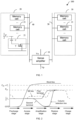
- an embodiment of the present application provides a memory 100.
- the memory 100 includes a sense amplifier 10 and a plurality of memory cells 21.
- a plurality of memory cells 21 constitute a first storage array 20, and a plurality of memory cells 21 constitute a second storage array 30.
- Each memory cell 21 in the first storage array 20 is connected to a bit line 40 of the first storage array 20, and each memory cell 21 in the second storage array 30 is connected to a bit line 50 of the second storage array 30.
- the sense amplifier 10 is located between the first storage array 20 and the second storage array 30, a first terminal of the sense amplifier 10 is connected to a first power supply terminal, a second terminal of the sense amplifier 10 is connected to a second power supply terminal, a third terminal of the sense amplifier 10 is connected to the bit line 40 of the first storage array 20, and a fourth terminal of the sense amplifier 10 is connected to the bit line 40 of the second storage array 30.
- Each memory cell 21 is configured to store one-bit data
- the bit line 40 of the first storage array 20 is configured to access data stored inside each memory cell 21 in the first storage array 20
- the bit line 50 of the second storage array 30 is configured to access data stored inside each memory cell 21 in the second storage array 30.
- the sense amplifier 10 is configured to amplify the data stored in each memory cell 21, and present the data on the bit line 40 of the first storage array 20 and the bit line 50 of the second storage array 30.
- the sense amplifier 10 is further configured to: after a data read operation is completed once, restore the memory cell 21 to a state before the read operation.
- Each memory cell 21 includes a storage capacitor C and an access transistor T, a first terminal of the storage capacitor C is connected to a fixed power supply, which is, for example, 0.5 V CC , a second terminal of the storage capacitor C is connected to a first terminal of the access transistor T, a second terminal of the access transistor T is connected to the bit line 40, and a control terminal of the access transistor T is connected to a word line.
- a fixed power supply which is, for example, 0.5 V CC
- a second terminal of the storage capacitor C is connected to a first terminal of the access transistor T
- a second terminal of the access transistor T is connected to the bit line 40
- a control terminal of the access transistor T is connected to a word line.
- the access transistor T is configured to control whether to allow or forbid to read or rewrite information stored in the storage capacitor C.
- bit line 40 when data in a specific memory cell 21 in the first storage array 20 is read, the bit line of the first storage array 20 is referred to as a bit line 40, and the bit line of the second storage array 30 is referred to as a reference bit line 50.
- bit line 40 When data in a specific memory cell 21 in the second storage array 30 is read, the bit line of the second storage array 30 is referred to as a bit line 40, and the bit line of the first storage array 20 is referred to as a reference bit line 50.
- reading data includes a precharge stage, an access stage, an amplification stage, and a restore stage.
- both a voltage of the bit line 40 of the first storage array 20 and a voltage of the reference bit line 50 are pulled up to a reference voltage, and the reference voltage is a voltage of a fixed power supply connected to the storage capacitor C, which is, for example, 0.5 V CC .
- a signal on a word line corresponding to the accessed memory cell 21 is controlled, such that an access transistor T in the accessed memory cell 21 is on, and the storage capacitor C enables the voltage of the bit line 40 to rise.
- the voltage of the bit line 40 is higher than the reference voltage, such that the sense amplifier 10 pulls the voltage of the bit line 40 up to a first preset value, and pulls the voltage of the reference bit line 50 down to a second preset value, the voltage of the bit line 40 is higher than the voltage of the reference bit line 50, and a voltage difference between the bit line 40 and the reference bit line 50 may reflect that data in the accessed memory cell 21 is "1".
- the sense amplifier 10 stabilizes the voltages of the bit line 40 and the reference bit line 50 at logical data "1"
- the bit line 40 further charges the storage capacitor C, and after a specific time of charging, charge in the storage capacitor C is restored to a state before the read operation.
- a signal inside a line is selected through a control column, such that an external read circuit may read the data stored in the accessed memory cell 21 on the bit line 40 and the reference bit line 50.
- the present application provides a sense amplifier, a memory, and a control method, aiming to provide a solution of improving data read accuracy and a data read success rate of the sense amplifier.
- a technical concept of the present application is that the controlled power supply module controls rates at which the amplification module pulls the voltage of the bit line 40 and the voltage of the reference bit line 50, such that the pull rates of the voltage of the bit line 40 and the voltage of the reference bit line 50 are within a rated pull rate range, and the data stored in the memory cell 21 has been stably presented on the bit line 40 and the reference bit line 50 when the external read circuit reads the data presented on the bit line 40 and the reference bit line 50, thereby further improving a data read success rate and data read accuracy.
- the sense amplifier 10 includes an amplification module 101 and a controlled power supply module 102, and the amplification module 101 is connected to the controlled power supply module 102.
- the amplification module 101 is configured to amplify a voltage difference between a bit line 40 and a reference bit line 50 when the sense amplifier 10 is at an amplification stage.
- the controlled power supply module 102 is configured to determine a drive parameter according to a first rated pull rate range and a second rated pull rate range, and supply power to the amplification module 101 according to the drive parameter.
- the amplification module 101 pulls a voltage of the bit line 40 or a voltage of the reference bit line 50 to a first preset value at a first rated pull rate and pulls the voltage of the reference bit line 50 or the voltage of the bit line 40 to a second preset value at a second rated pull rate at the amplification stage.
- the first rated pull rate is within the first rated pull rate range
- the second rated pull rate is within the second rated pull rate range.
- a difference between the first preset value and the second preset value can reflect logical data "1" or logical data "0".
- the first preset value may be, for example, V CC
- the second preset value may be, for example, 0.
- the amplification module 101 pulls the voltage of the bit line 40 to the first preset value at the first rated pull rate and pulls the voltage of the reference bit line 50 to the second preset value at the second rated pull rate at the amplification stage.
- the amplification module 101 pulls the voltage of the reference bit line 50 to the first preset value at the first rated pull rate and pulls the voltage of the bit line 40 to the second preset value at the second rated pull rate at the amplification stage.
- a pull rate of the voltage of the bit line 40 and a pull rate of the voltage of the reference bit line 50 affect a data read success rate and data read accuracy.
- the controlled power supply module 102 determines a drive parameter according to a first rated pull rate range and a second rated pull rate range, and supplies power to the amplification module 101 according to the drive parameter, to control the amplification module 101 to pull a voltage of the bit line 40 or a voltage of the reference bit line 50 to a first preset value at a first rated pull rate and pull the voltage of the reference bit line 50 or the voltage of the bit line 40 to a second preset value at a second rated pull rate at the amplification stage.
- the first rated pull rate is within the first rated pull rate range
- the second rated pull rate is within the second rated pull rate range.
- the first rated pull rate range and the second rated pull rate range are determined according to a time sequence of selected signals on a column selection line, a time sequence of signals on a word line connected to the memory cell 21, and voltages of the bit line 40 and the reference bit line 50.
- the first rated pull rate range and the second rated pull rate range may be further obtained by testing the sense amplifier 10, to ensure that data on the bit line 40 and the reference bit line 50 can be accurately read. For example, as shown in FIG. 4a , FIG. 4b, and FIG. 4c , an embodiment is provided. It is assumed that a rising rate of v p ( t ) in FIG.
- the first rated pull rate range may be from 2 to 4 (a corresponding speed unit is V/ps), and a first rated pull rate in FIG. 4c may be 3. It should be noted that one embodiment is merely provided herein, both the first rated pull rate range and the first rated pull rate are not limited thereto. Similarly, the second rated pull rate range and the second rated pull rate may be obtained in a similar manner. This is not limited herein.
- the sense amplifier 10 When the sense amplifier 10 is at the amplification stage, the voltage of the bit line 40 or the reference bit line 50 is pulled at a pull rate within the first rated pull rate range, and the voltage of the reference bit line 50 or the bit line 40 is pulled at a pull rate within the second rated pull rate range.
- the sense amplifier 10 When the sense amplifier 10 is at a restore stage, the external read circuit reads data presented on the bit line 40 and the reference bit line 50. In this case, the data stored in the memory cell 21 has been stably presented on the bit line 40 and the reference bit line 50, such that the external data read circuit can accurately read the data presented on the bit line 40 and the reference bit line 50.
- the controlled power supply module controls rates at which the amplification module pulls the voltage of the bit line 40 and the voltage of the reference bit line 50, such that the pull rates of the voltage of the bit line 40 and the voltage of the reference bit line 50 are within a rated pull rate range, and the data stored in the memory cell has been stably presented on the bit line 40 and the reference bit line 50 when the external read circuit reads the data presented on the bit line 40 and the reference bit line 50, thereby further improving a data read success rate and data read accuracy.
- FIG. 5 another embodiment of the present application provides a sense amplifier 10, the sense amplifier 10 includes an amplification module 101 and a controlled power supply module 102, and the amplification module 101 is connected to the controlled power supply module 102.
- the controlled power supply module 102 includes a first controlled power supply unit 1021, a second controlled power supply unit 1022, and a control unit 1025.
- the amplification module 101 is provided with a first terminal, a second terminal, a third terminal, and a fourth terminal.
- An output terminal of the first controlled power supply unit 1021 is connected to the first terminal of the amplification module 101, an output terminal of the second controlled power supply unit 1022 is connected to the second terminal of the amplification module 101, the third terminal of the amplification module 101 is connected to a bit line, and the fourth terminal of the amplification module is connected to a reference bit line.
- the control unit 1025 is connected to a control terminal of the first controlled power supply unit 1021, and the control unit 1025 is further connected to a control terminal of the second controlled power supply unit 1022.
- Both the first controlled power supply unit 1021 and the second controlled power supply unit 1022 are configured to supply power to the amplification module 101.
- the control unit 1025 is configured to determine a drive parameter according to a first rated pull rate and a second rated pull rate, and control, according to a drive parameter, a first controlled current source 1023 and a second controlled current source 1024 to supply power to the amplification module 101.
- the amplification module 101 pulls a voltage of the bit line 40 or a voltage of the reference bit line 50 to a first preset value at a first rated pull rate and pulls the voltage of the reference bit line 50 or the voltage of the bit line 40 to a second preset value at a second rated pull rate at an amplification stage.
- a voltage provided by the first controlled power supply unit 1021 is higher than a voltage provided by the second controlled power supply unit 1022, and data "1" is presented when the voltage of the bit line 40 is higher than the voltage of the reference bit line 50.
- the first controlled power supply unit 1021 controls the amplification module 101 to pull the voltage of the bit line 40 to the first preset value at the first rated pull rate
- the second controlled power supply unit 1022 controls the amplification module 101 to pull the voltage of the reference bit line 50 to the second preset value at the second rated pull rate.
- the first controlled power supply unit 1021 controls the amplification module 101 to pull the voltage of the reference bit line 50 to the first preset value at the first rated pull rate
- the second controlled power supply unit 1022 controls the amplification module 101 to pull the voltage of the bit line 40 to the second preset value at the second rated pull rate.
- the first preset value may be, for example, V CC
- the second preset value may be, for example, 0.
- the sense amplifier 10 When the sense amplifier 10 is at the amplification stage, the voltage of the bit line 40 or the voltage of the reference bit line 50 is pulled at a pull rate within the first rated pull rate range, and the voltage of the reference bit line 50 or the voltage of the bit line 40 is pulled at a pull rate within the second rated pull rate range.
- the sense amplifier 10 When the sense amplifier 10 is at a restore stage, the external read circuit reads data presented on the bit line 40 and the reference bit line 50. In this case, the data stored in the memory cell 21 has been stably presented on the bit line 40 and the reference bit line 50, such that the external data read circuit can accurately read the data presented on the bit line 40 and the reference bit line 50.
- the first controlled power supply unit 1021 includes N first controlled current sources 1023.
- Each first controlled current source 1023 is provided with a control terminal, a first terminal, and a second terminal.
- the second terminal of each first controlled current source 1023 is the output terminal of the first controlled power supply unit 1021
- the control terminal of each first controlled current source 1023 is the control terminal of the first controlled power supply unit 1021.
- the first terminal of the first controlled current source 1023 is connected to a first power supply terminal
- the second terminal of the first controlled current source 1023 is connected to the first terminal of the amplification module 101
- the control terminal of the first controlled current source 1023 is connected to the control unit 1025, where N is a positive integer.
- the second controlled power supply unit 1022 includes N second controlled current sources 1024, and the second controlled power supply unit 1022 is provided with a control terminal, a first terminal, and a second terminal.
- the second terminal of each second controlled current source 1024 is the output terminal of the second controlled power supply unit 1022
- the control terminal of each second controlled current source 1024 is the control terminal of the second controlled power supply unit 1022.
- the first terminal of the second controlled current source 1024 is connected to a second power supply terminal
- the second terminal of the second controlled current source 1024 is connected to the second terminal of the amplification module 101
- the control terminal of the second controlled current source 1024 is connected to the control unit 1025.
- the control unit 1025 is configured to: determine a first drive current range according to the first rated pull rate range, and select at least one first target current source in the N first controlled current sources 1023, such that a total current provided by the at least one first target current source is within the first drive current range; and generate a first control signal used to control the first target current source to work, such that the first controlled power supply unit 1021 controls the amplification module 101 to pull the voltage of the bit line 40 to the first preset value at the first rated pull rate at the amplification stage.
- the control unit 1025 is further configured to: determine a second drive current range according to the second rated pull rate range, and select at least one second target current source in the N second controlled current sources 1024, such that a total current provided by the at least one second target current source is within the second drive current range; and generate a second control signal used to control the second target current source to work, such that the second controlled power supply unit 1022 controls the amplification module 101 to pull the voltage of the reference bit line 50 to the second preset value at the second rated pull rate at the amplification stage.
- the control unit 1025 is configured to determine a first drive current range according to the first rated pull rate range, and select at least one first target current source in the N first controlled current sources 1024, such that a total current provided by the at least one first target current source is within the first drive current range; and generate a third control signal used to control the first target current source to work, such that the first controlled power supply unit 1022 controls the amplification module 101 to pull the voltage of the reference bit line 50 to the first preset value at the first rated pull rate at the amplification stage.
- the control unit 1025 is further configured to: determine a second drive current range according to the second rated pull rate range, and select at least one second target current source in the N second controlled current sources 1023, such that a total current provided by the at least one second target current source is within the second drive current range; and generate a fourth control signal used to control the second target current source to work, such that the second controlled power supply unit 1021 controls the amplification module 101 to pull the voltage of the bit line 40 to the second preset value at the second rated pull rate at the amplification stage.
- an i th first controlled current source 1023 provides a drive current 2 i -1 ⁇ I b
- a j th second controlled current source 1024 provides a drive current 2 j -1 ⁇ I b
- I b represents a unit current.
- the N first controlled current sources 1023 may provide 2 N - 1 levels of drive current
- the N second controlled current sources 1024 may also provide 2 N - 1 levels of drive current.
- Rates at which the amplification module 101 pulls the voltage of the bit line 40 and the voltage of the reference bit line 50 can be accurately adjusted by adjusting an amplitude value of the unit current, to pull the voltage of the bit line 40 or the voltage of the reference bit line 50 to the first preset value at the first rated pull rate and pull the voltage of the reference bit line 50 or the voltage of the bit line 40 to the second preset value at the second rated pull rate at the amplification stage.
- the first controlled power supply unit controls the amplification module to pull the voltage of the bit line 40 or the voltage of the reference bit line 50 at the first rated pull rate
- the second controlled power supply unit controls the amplification module to pull the voltage of the reference bit line 50 or the voltage of the bit line 40 at the second rated pull rate, such that data stored in the memory cell has been stably presented on the bit line 40 and the reference bit line 50 when the external read circuit reads the data presented on the bit line 40 and the reference bit line 50 at the restore stage, and the external data read circuit can accurately read the data presented on the bit line 40 and the reference bit line 50.
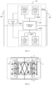
- an embodiment of the present application provides a sense amplifier 10, the sense amplifier 10 includes an amplification module 101 and a controlled power supply module 102, and the amplification module 101 is connected to the controlled power supply module 102.
- the amplification module 101 includes at least one cross-coupled amplifier circuit, each cross-coupled amplifier circuit is provided with a first terminal, a second terminal, a third terminal, and a fourth terminal, the first terminal of the cross-coupled amplifier circuit is connected to an output terminal of a first controlled power supply unit 1021, the second terminal of the cross-coupled amplifier circuit is connected to an output terminal of the second controlled power supply unit 1022, the third terminal of the cross-coupled amplifier circuit is connected to a bit line 40, and the fourth terminal of the cross-coupled amplifier circuit is connected to a reference bit line 50.
- the cross-coupled amplifier circuit includes: a first transistor T1, a second transistor T2, a third transistor T3, and a fourth transistor T4.
- a first terminal of the first transistor T1 is the first terminal of the cross-coupled amplifier circuit
- a second terminal of the second transistor T2 is the second terminal of the cross-coupled amplifier circuit
- a second terminal of the first transistor T1 is the third terminal of the cross-coupled amplifier circuit
- a second terminal of the third transistor T3 is the fourth terminal of the cross-coupled amplifier circuit.
- the second terminal of the first transistor T1 is connected to a first terminal of the second transistor T2, the second terminal of the third transistor T3 is connected to a first terminal of the fourth transistor T4, the first terminal of the first transistor T1 is connected to a first terminal of the third transistor T3, and the second terminal of the second transistor T2 is connected to a second terminal of the fourth transistor T4.
- a control terminal of the first transistor T1 is connected to the second terminal of the third transistor T3, a control terminal of the second transistor T2 is connected to the second terminal of the third transistor T3, a control terminal of the third transistor T3 is connected to the second terminal of the first transistor T1, and a control terminal of the fourth transistor T4 is connected to the second terminal of the first transistor T1.
- the first transistor T1 and the third transistor T3 are P-type transistors, and the second transistor T2 and the fourth transistor T4 are N-type transistors.
- the controlled power supply module 102 includes the first controlled power supply unit 1021 and the second controlled power supply unit 1022, the first controlled power supply unit 1021 includes N first controlled current sources 1023, and the second controlled power supply unit 1022 includes N second controlled current sources 1024.
- the first controlled current source 1023 is a P-type transistor, and the second controlled current source 1024 is an N-type transistor.
- a process of reading data "1" from one memory cell 21 in a first storage array 20 is described below.
- both a voltage of the bit line 40 of the first storage array 20 and a voltage of the reference bit line 50 are pulled up to a reference voltage, and the reference voltage may be a voltage 0.5 V CC of a fixed power supply connected to the storage capacitor C.
- a signal on a word line corresponding to the accessed memory cell 21 is controlled, such that an access transistor T in the accessed memory cell 21 is on, and the storage capacitor C pulls the voltage of the bit line 40 to rise.
- the voltage of the bit line 40 is higher than the reference voltage, such that the first transistor T1 and the fourth transistor T4 are on, and the second transistor T2 and the third transistor T3 are off. If the first transistor T1 is on and the third transistor T3 is off, the first controlled power supply unit 1021 pulls the voltage of the bit line 40 up to a first preset value.
- the first controlled power supply unit 1021 includes a plurality of P-type transistors. In this case, a rate at which the first controlled power supply unit 1021 pulls the voltage of the bit line 40 and that is used when the first transistor T1 is on may be controlled by controlling a quantity of P-type transistors in an on state.
- the second controlled power supply unit 1022 pulls to the voltage of the reference bit line 50 down to a second preset value.
- the second controlled power supply unit 1022 includes a plurality of N-type transistors. In this case, a rate at which the second controlled power supply unit 1022 pulls the voltage of the reference bit line 50 and that is used when the fourth transistor T4 is off may be controlled by controlling a quantity of N-type transistors in an on state.
- the quantity of P-type transistors in the on state in the first controlled power supply unit 1021 and the quantity of N-type transistors in the on state in the second controlled power supply unit 1022 are controlled, such that the voltage of the bit line 40 is pulled to the first preset value at a first rated pull rate and the voltage of the reference bit line 50 is pulled to the second preset value at a second rated pull rate, and a voltage difference between the bit line 40 and the reference bit line 50 can stably reflect that data in the accessed memory cell 21 is "1".
- the sense amplifier 10 has stabilized the voltage of the bit line 40 and the voltage of the reference bit line 50 at logical data "1"
- the bit line 40 charges the storage capacitor C, and after a specific time of charging, charge in the storage capacitor C is restored to a state before the read operation.
- a signal inside a line is selected through a control column, such that an external read circuit may read the data stored in the accessed memory cell 21 on the bit line 40 and the reference bit line 50.
- an i th P-type transistor in the first controlled power supply unit 1021 may provide a drive current 2 i -1 ⁇ I b
- a j th N-type transistor in the second controlled power supply unit 1022 may provide a drive current 2 j -1 ⁇ I b
- I b represents a unit current.
- the first controlled power supply unit 1021 may provide 2 N - 1 levels of drive current
- the second controlled power supply unit 1022 may also provide 2 N - 1 levels of drive current, such that the controlled power supply module 102 can provide 2 N - 1 levels of drive current.
- the first controlled power supply unit 1021 includes three P-type transistors.
- a drive current that may be provided by the 1 st P-type transistor is I b
- a drive current that may be provided by the 2 nd P-type transistor is 2I b
- a drive current that may be provided by the 3 rd P-type transistor is 4 I b
- the second controlled power supply unit 1022 includes three N-type transistors.
- a drive current that may be provided by the 1 st N-type transistor is I b
- a drive current that may be provided by the 2 nd N-type transistor is 2I b
- a drive current that may be provided by the 3 rd N-type transistor is 4I b .
- the controlled power supply module 102 may provide 7 levels of drive current. Control signals of N-type transistors and P-type transistors at each level are shown in Table 1 and Table 2.”1" represents a high level control signal and "0" represents a low level control signal. Table 1 Control signal of an N-type transistor 3 rd N-type transistor 2 nd N-type transistor 1 st N-type transistor Level of a drive current 0 0 1 I b 0 1 0 2 I b 0 1 1 3 I b 1 0 0 4 I b 1 0 1 5 I b 1 1 0 6 I b 1 1 1 7 I b Table 2 Control signal of a P-type transistor 3 rd P-type transistor 2 nd P-type transistor 1 st P-type transistor Level of a drive current 1 1 0 I b 1 0 1 2 I b 1 0 0 3 I b 0 1 1 4 I b 0 1 0 5 I b 0 0 1 6 I b 0 0 0
- the quantity of P-type transistors in the on state and the quantity of N-type transistors in the on state are controlled, to control the controlled power supply module to provide a level of a drive current to the amplification module, so as to control rates at which the amplification module pulls the voltage of the bit line 40 and the voltage of the reference bit line 50 to be in a rated range, such that the bit line 40 and the reference bit line 50 can stably present the data stored in the memory cell at the restore stage, thereby improving data read accuracy and a data read success rate.
- an embodiment of the present application provides a sense amplifier 10, the sense amplifier 10 includes an amplification module 101 and a controlled power supply module 102, and the amplification module 101 is connected to the controlled power supply module 102.
- the amplification module 101 includes at least one cross-coupled amplifier circuit, each cross-coupled amplifier circuit is provided with a first terminal, a second terminal, a third terminal, and a fourth terminal, the first terminal of the cross-coupled amplifier circuit is connected to an output terminal of a first controlled power supply unit 1021, the second terminal of the cross-coupled amplifier circuit is connected to an output terminal of the second controlled power supply unit 1022, the third terminal of the cross-coupled amplifier circuit is connected to a bit line 40, and the fourth terminal of the cross-coupled amplifier circuit is connected to a reference bit line 50.
- the cross-coupled amplifier circuit has an offset elimination function, and the cross-coupled circuit specifically includes: a fifth transistor T5, a sixth transistor T6, a seventh transistor T7, an eighth transistor T8, a first switch K1, a second switch K2, a third switch K3, and a fourth switch K4.
- a first terminal of the fifth transistor T5 is the first terminal of the cross-coupled amplifier circuit
- a second terminal of the sixth transistor T6 is the second terminal of the cross-coupled amplifier circuit
- a second terminal of the fifth transistor T5 is the third terminal of the cross-coupled amplifier circuit
- a second terminal of the seventh transistor T7 is the fourth terminal of the cross-coupled amplifier circuit.
- the second terminal of the fifth transistor T5 is connected to a first terminal of the sixth transistor T6, the second terminal of the seventh transistor T7 is connected to a first terminal of the eighth transistor T8, the first terminal of the fifth transistor T5 is connected to a first terminal of the seventh transistor T7, and the second terminal of the sixth transistor T6 is connected to a second terminal of the eighth transistor T8.
- a control terminal of the fifth transistor T5 is connected to the second terminal of the seventh transistor T7, a control terminal of the sixth transistor T6 is connected to the second terminal of the seventh transistor T7 through the first switch K1, and the control terminal of the sixth transistor T6 is connected to the first terminal of the sixth transistor T6 through the third switch K3.
- a control terminal of the seventh transistor T7 is connected to the second terminal of the fifth transistor T5, a control terminal of the eighth transistor T8 is connected to the second terminal of the fifth transistor T5 through the second switch K2, and the control terminal of the eighth transistor T8 is connected to the first terminal of the eighth transistor T8 through the fourth switch K4.
- the fifth transistor T5 and the seventh transistor T7 are P-type transistors, and the sixth transistor T6 and the eighth transistor T8 are N-type transistors.
- the controlled power supply module 102 includes the first controlled power supply unit 1021 and the second controlled power supply unit 1022, the first controlled power supply unit 1021 includes N first controlled current sources 1023, and the second controlled power supply unit 1022 includes N second controlled current sources 1024.
- the first controlled current source 1023 is a P-type transistor, and the second controlled current source 1024 is a P-type transistor.
- a data read process of the sense amplifier provided in this embodiment further includes an offset elimination stage.
- a connection line between the second terminal of the fifth transistor T5 and the first terminal of the sixth transistor T6 is referred to as an internal bit line 70 of a first storage array 20
- a connection line between the second terminal of the seventh transistor T7 and the first terminal of the eighth transistor T8 is referred to as an internal reference bit line 60 of the first storage array 20.
- reading data includes an idle stage, an offset elimination stage, a precharge stage, an access stage, an amplification stage, and a restore stage.
- the third switch K3 and the fourth switch K4 are closed, and the first switch K1 and the second switch K2 are also closed.
- the first terminal of the sixth transistor T6 is short circuited to the control terminal, and the first terminal of the eighth transistor T8 is short circuited to the control terminal.
- the charge switches CK1 and CK2 are closed, and the internal bit line 70 and the internal reference bit line 60 are charged through a charge power supply.
- the bit line 40, the reference bit line 50, the internal bit line 70, and the internal reference bit line 60 are all charged to 0.5 V CC .
- the first switch K1 and the second switch K2 are disconnected, and the third switch K3 and the fourth switch K4 are still closed.
- At least one N-type transistor of N11, N12, N13 is controlled according to a waveform in the figure
- at least one N-type transistor of N21, N22, N23 is controlled according to a waveform in the figure, such that the first controlled power supply unit 1021 and the second controlled power supply unit 1022 supply power to the cross-coupled amplifier circuit.
- the sixth transistor T6 is connected to the eighth transistor T8 through a diode.
- a compensation voltage occurs on the bit line 40 and the reference bit line 50, and the compensation voltage may eliminate a manufacturing difference in the N-type transistor or the P-type transistor (which may be referred to as an offset voltage). For example, the voltage on the bit line 40 minus the voltage on the reference bit line 50 equals the offset voltage, or the voltage on the reference bit line 50 minus the voltage on the bit line 40 equals the offset voltage.
- the first switch K1 to the fourth switch K4 are all disconnected. Both a voltage of the internal bit line 70 of the first storage array 20 and a voltage of the internal reference bit line 60 are pulled up to a reference voltage, and the reference voltage is a voltage of a fixed power supply connected to the storage capacitor C. In an embodiment, the voltage of the fixed power supply is 0.5 V CC .
- the first switch K1 and the second switch K2 are closed, the third switch K3 and the fourth switch K4 are still disconnected, and the compensation voltage is still reserved on the bit line 40 and the reference bit line 50.
- the voltage on the bit line 40 is higher than the voltage of the reference bit line 50, and a difference is a compensation voltage Vos.
- the voltage on the bit line 40 is still higher than the voltage of the reference bit line 50, and a difference is also the compensation voltage Vos.
- an offset between threshold voltages of T6 and T8 is Vos
- an offset between threshold voltages of T5 and T7 is Vos
- an offset between threshold voltages that occur on T6 and T5 together with T8 and T7 is Vos
- a signal on a word line corresponding to the accessed memory cell 21 is controlled, such that an access transistor T in the accessed memory cell 21 is on, and the storage capacitor C enables the voltage of the bit line 40 to rise.
- a quantity of transistors in an on state is controlled, to control the controlled power supply module to provide a level of a drive current to the amplification module, so as to control rates at which the amplification module pulls the bit line 40 and the reference bit line 50 to be in a rated range, such that the bit line 40 and the reference bit line 50 can stably present the data stored in the memory cell at the restore stage, thereby improving data read accuracy and a data read success rate.
- the present application provides a control method of a sense amplifier.
- a structure of the sense amplifier has been described in detail in the foregoing embodiment, and details are not described herein again.
- the control method specifically includes the following step.
- the first rated pull rate range and the second rated pull rate range are determined according to a time sequence of selected signals on a column selection line, a time sequence of signals on a word line connected to the memory cell, and voltages of a bit line and a reference bit line.
- the first rated pull rate range and the second rated pull rate range are further obtained by testing the sense amplifier, to ensure that data on the bit line and the reference bit line are accurately read.
- the sense amplifier is tested, to obtain a mapping relationship between pull rates at which the sense amplifier pulls the bit line and the reference bit line and a drive parameter of the controlled power supply module, and then the drive parameter of the controlled power supply module is determined according to the mapping relationship and the two rated pull rate ranges.
- the control signal is generated according to the drive parameter, to control the controlled power supply module to supply power to an amplification module according to the drive parameter, and further control the controlled power supply module to control the amplification module to pull a voltage of the bit line or a voltage of the reference bit line to a first preset value at a first rated pull rate and pull the voltage of the reference bit line or the voltage of the bit line to a second preset value at a second rated pull rate at an amplification stage.
- the first rated pull rate is within the first rated pull rate range
- the second rated pull rate is within the second rated pull rate range.
- the drive parameter output by the controlled power supply module is controlled, to control rates at which the amplification module pulls the voltage of the bit line and the voltage of the reference bit line, such that the pull rates of the voltage of the bit line and the voltage of the reference bit line are within a rated pull rate range, and the data stored in the memory cell has been stably presented on the bit line and the reference bit line when the external read circuit reads the data presented on the bit line and the reference bit line, thereby further improving a data read success rate and data read accuracy.
- Another embodiment of the present application provides a control method of a sense amplifier.
- the control method specifically includes the following step.
- S2002 Determine a drive parameter of a controlled power supply module according to the first rated pull rate range and the second rated pull rate range.
- a first drive current range is determined according to the first rated pull rate range, and a second drive current range is determined according to the second rated pull rate range.
- the first drive current range is a drive parameter of a first controlled current source
- the second drive current range is a drive parameter of a second controlled current source.
- At least one first target current source is selected in N first controlled current sources, such that a total current provided by the at least one first target current source is within the first drive current range; and a first control signal used to control the first target current source to work is generated, such that a first controlled power supply unit controls an amplification module to pull the voltage of the bit line to a first preset value at a first rated pull rate at an amplification stage.
- At least one second target current source is selected in N second controlled current sources, such that a total current provided by the at least one second target current source is within the second drive current range; and a second control signal used to control the second target current source to work is generated, such that a second controlled power supply unit controls the amplification module to pull the voltage of the reference bit line to a second preset value at a second rated pull rate at the amplification stage.
- At least one first target current source is selected in N first controlled current sources, such that a total current provided by the at least one first target current source is within the first drive current range; and a third control signal used to control the first target current source to work is generated, such that a first controlled power supply unit controls an amplification module to pull the voltage of the reference bit line to a first preset value at a first rated pull rate at an amplification stage.
- At least one second target current source is selected in N second controlled current sources, such that a total current provided by the at least one second target current source is within the second drive current range; and a fourth control signal used to control the second target current source to work is generated, such that a second controlled power supply unit controls the amplification module to pull the voltage of the bit line to a second preset value at a second rated pull rate at the amplification stage.
- the first controlled power supply unit controls the amplification module to pull the voltage of the bit line or the voltage of the reference bit line at the first rated pull rate
- the second controlled power supply unit controls the amplification module to pull the voltage of the reference bit line or the voltage of the bit line at the second rated pull rate, such that data stored in the memory cell has been stably presented on the bit line and the reference bit line when an external read circuit reads the data presented on the bit line and the reference bit line at a restore stage, and the external data read circuit can accurately read the data presented on the bit line and the reference bit line.
Landscapes
- Engineering & Computer Science (AREA)
- Power Engineering (AREA)
- Microelectronics & Electronic Packaging (AREA)
- Computer Hardware Design (AREA)
- Dram (AREA)
- Amplifiers (AREA)
Claims (15)
- Ein Leseverstärker (10), umfassend:ein Verstärkungsmodul (101), das so konfiguriert ist, dass es: wenn sich der Leseverstärker (10) in einer Verstärkungsstufe befindet, eine Spannungsdifferenz zwischen einer Bitleitung (40) und einer Referenzbitleitung (50) verstärkt;dadurch gekennzeichnet, dass es Folgendes umfasst:ein gesteuertes Stromversorgungsmodul (102), das mit dem Verstärkungsmodul (101) verbunden ist und konfiguriert ist: zum Bestimmen eines Antriebsstrombereichs gemäß einem ersten Nenn-Zugratenbereich und einem zweiten Nenn-Zugratenbereich und zum Zuführen von Strom zu dem Verstärkungsmodul (101) gemäß dem Antriebsstrombereich, um das Verstärkungsmodul (101) zu steuern, um eine Spannung der Bitleitung (40) oder eine Spannung der Referenzbitleitung (50) auf einen ersten voreingestellten Wert bei einer ersten Nenn-Zugrate an der Verstärkungsstufe zu ziehen und die Spannung der Referenzbitleitung (50) oder die Spannung der Bitleitung (40) auf einen zweiten voreingestellten Wert bei einer zweiten Nenn-Zugrate an der Verstärkungsstufe zu ziehen, wobeider erste Nenn-Zugratenbereich und der zweite Nenn-Zugratenbereich jeweils ein Nennbereich einer Spannungsrate sind, mit der das Verstärkungsmodul (101) die Spannung der Bitleitung (40) oder die Spannung der Referenzbitleitung (50) auf den ersten voreingestellten Wert an der Verstärkungsstufe zieht, und einen Nennbereich der Spannungsrate, mit der das Verstärkungsmodul (101) die Spannung der Bitleitung (40) oder die Spannung der Referenzbitleitung (50) auf den zweiten voreingestellten Wert an der Verstärkungsstufe zieht, und die erste Nenn-Zugrate innerhalb des ersten Nenn-Zugratenbereichs liegt und die zweite Nenn-Zugrate innerhalb des zweiten Nenn-Zugratenbereichs liegt;das gesteuerte Stromversorgungsmodul (102) so konfiguriert ist, dass es entsprechend dem Antriebsstrombereich ein Steuersignal erzeugt, das zur Steuerung des gesteuerten Stromversorgungsmoduls (102) verwendet wird, um einen Pegel eines Antriebsstroms an das Verstärkungsmodul (101) zu liefern, um die Spannung der Bitleitung (40) oder die Spannung der Referenzbitleitung (50) auf den ersten voreingestellten Wert bei der ersten Nenn-Zugrate in der Verstärkungsstufe zu ziehen und die Spannung der Referenzbitleitung (50) oder die Spannung der Bitleitung (40) auf den zweiten voreingestellten Wert bei der zweiten Nenn-Zugrate in der Verstärkungsstufe zu ziehen; unddas gesteuerte Stromversorgungsmodul (102) ist ferner so konfiguriert, dass es den Antriebsstrombereich gemäß des ersten Nenn-Zugratenbereichs und des zweiten Nenn-Zugratenbereichs folgendermaßen bestimmt: Testen des Leseverstärkers, um eine Abbildungsbeziehung zwischen den Zugraten, mit denen die Bitleitung und die Referenzbitleitung gezogen werden, und dem Antriebsstrombereich zu erhalten, und Bestimmen des Antriebsstrombereichs gemäß der Abbildungsbeziehung und dem ersten Nenn-Zugratenbereich und dem zweiten Nenn-Zugratenbereich.
- Leseverstärker (10) nach Anspruch 1, wobei das gesteuerte Stromversorgungsmodul (102) Folgendes umfasst:eine erste gesteuerte Stromversorgungseinheit (1021), die mit einem ersten Anschluss des Verstärkungsmoduls (101) verbunden und so konfiguriert ist, dass sie das Verstärkungsmodul (101) mit Strom versorgt;eine zweite gesteuerte Stromversorgungseinheit (1022), die mit einem zweiten Anschluss des Verstärkungsmoduls (101) verbunden und so konfiguriert ist, dass sie dem Verstärkungsmodul (101) Strom zuführt; undeine Steuereinheit (1025), die mit der ersten gesteuerten Stromversorgungseinheit (1021) verbunden ist, ferner mit der zweiten gesteuerten Stromversorgungseinheit (1022) verbunden ist und konfiguriert ist, um: den Antriebsstrombereich gemäß dem ersten Nenn-Zugratenbereich und dem zweiten Nenn-Zugratenbereich zu bestimmen und gemäß dem Antriebsstrombereich eine oder mehrere erste gesteuerte Stromquellen (1023) und eine oder mehrere zweite gesteuerte Stromquellen (1024) zu steuern, um dem Verstärkungsmodul (101) Strom zuzuführen.
- Leseverstärker (10) nach Anspruch 2, wobei die erste gesteuerte Stromversorgungseinheit (1021) Folgendes umfasst:N erste gesteuerte Stromquellen (1023), wobei jede der ersten gesteuerten Stromquellen (1023) mit einem Steueranschluss, einem ersten Anschluss und einem zweiten Anschluss versehen ist, der erste Anschluss der ersten gesteuerten Stromquelle (1023) mit einem ersten Stromversorgungsanschluss verbunden ist, der zweite Anschluss der ersten gesteuerten Stromquelle (1023) mit dem ersten Anschluss des Verstärkungsmoduls (101) verbunden ist, und der Steueranschluss der ersten gesteuerten Stromquelle (1023) mit der Steuereinheit (1025) verbunden ist, wobei N eine positive ganze Zahl ist;wobei die zweite gesteuerte Stromversorgungseinheit umfasst: N zweite gesteuerte Stromquellen (1024), wobei jede der zweiten gesteuerten Stromquellen (1024) mit einem Steueranschluss, einem ersten Anschluss und einem zweiten Anschluss versehen ist, der erste Anschluss der zweiten gesteuerten Stromquelle (1024) mit einem zweiten Stromversorgungsanschluss verbunden ist, der zweite Anschluss der zweiten gesteuerten Stromquelle (1024) mit dem zweiten Anschluss des Verstärkungsmoduls (101) verbunden ist, und der Steueranschluss der zweiten gesteuerten Stromquelle (1024) mit der Steuereinheit (1025) verbunden ist.
- Leseverstärker (10) nach Anspruch 3, wobei die Steuereinheit (1025) zu Folgendem konfiguriert ist:einen ersten Antriebsstrombereich entsprechend dem ersten Nenn-Zugratenbereich bestimmen und einen zweiten Antriebsstrombereich entsprechend dem zweiten Nenn-Zugratenbereich bestimmen;mindestens eine erste Zielstromquelle in den N ersten gesteuerten Stromquellen (1023) auswählen und mindestens eine zweite Zielstromquelle in den N zweiten gesteuerten Stromquellen (1024) auswählen, wobei ein von der mindestens einen ersten Zielstromquelle gelieferter Gesamtstrom innerhalb des ersten Antriebsstrombereichs liegt und ein von der mindestens einen zweiten Zielstromquelle gelieferter Gesamtstrom innerhalb des zweiten Antriebsstrombereichs liegt; undein erstes Steuersignal erzeugen, das verwendet wird, um die erste Zielstromquelle zu steuern, damit sie arbeitet, und ein zweites Steuersignal erzeugen, das verwendet wird, um die zweite Zielstromquelle zu steuern, damit sie arbeitet, so dass die erste gesteuerte Stromversorgungseinheit (1021) das Verstärkungsmodul (101) steuert, um die Spannung der Bitleitung (40) auf den ersten voreingestellten Wert bei der ersten Nenn-Zugrate in der Verstärkungsstufe zu ziehen, und die zweite gesteuerte Stromversorgungseinheit (1022) das Verstärkungsmodul (101) steuert, um die Spannung der Referenz-Bitleitung (50) auf den zweiten voreingestellten Wert mit der zweiten Nenn-Zugrate an der Verstärkungsstufe zu ziehen.
- Leseverstärker (10) nach Anspruch 3, wobei der Antriebsstrombereich einen ersten Antriebsstrombereich und einen zweiten Antriebsstrombereich umfasst, und die Steuereinheit (1025) so konfiguriert ist, dass sie:den ersten Antriebsstrombereich entsprechend dem ersten Nenn-Zugratenbereich bestimmt und den zweiten Antriebsstrombereich entsprechend dem zweiten Nenn-Zugratenbereich bestimmt;mindestens eine erste Zielstromquelle aus den N ersten gesteuerten Stromquellen (1023) auswählt und mindestens eine zweite Zielstromquelle aus den N zweiten gesteuerten Stromquellen (1024) auswählt, wobei ein Gesamtstrom, der von der mindestens einen ersten Zielstromquelle bereitgestellt wird, innerhalb des zweiten Antriebsstrombereichs liegt, und ein Gesamtstrom, der von der mindestens einen zweiten Zielstromquelle bereitgestellt wird, innerhalb des ersten Antriebsstrombereichs liegt; undein drittes Steuersignal erzeugt, das verwendet wird, um die erste Zielstromquelle zu steuern, damit sie arbeitet, und ein viertes Steuersignal erzeugt, das verwendet wird, um die zweite Zielstromquelle zu steuern, damit sie arbeitet, so dass die erste gesteuerte Stromversorgungseinheit (1021) das Verstärkungsmodul (101) steuert, um die Spannung der Referenzbitleitung (50) auf den ersten voreingestellten Wert bei der ersten Nenn-Zugrate in der Verstärkungsstufe zu ziehen, und die zweite gesteuerte Stromversorgungseinheit (1022) das Verstärkungsmodul (101) steuert, um die Spannung der Bitleitung (40) auf den zweiten voreingestellten Wert bei der zweiten Nenn-Zugrate an der Verstärkungsstufe zu ziehen.
- Leseverstärker (10) nach einem der Ansprüche 3 bis 5, wobei ein Antriebsstrom, der von einer ith ersten gesteuerten Stromquelle bereitgestellt wird 2i-1 × Ib, ein von einer j th zweiten geregelten Stromquelle gelieferter Antriebsstrom ist 2 j-1 × Ib, und I b eine Stromeinheit darstellt.
- Leseverstärker (10) nach einem der Ansprüche 3 bis 5, wobei die erste gesteuerte Stromquelle (1023) ein P-Typ-Transistor ist und die zweite gesteuerte Stromquelle (1024) ein N-Typ-Transistor ist; oder die erste gesteuerte Stromquelle (1023) und die zweite gesteuerte Stromquelle (1024) beide N-Typ-Transistoren sind.
- Leseverstärker (10) nach einem der Ansprüche 2 bis 5, wobei das Verstärkungsmodul (101) Folgendes umfasst:
mindestens eine kreuzgekoppelte Verstärkerschaltung, wobei die kreuzgekoppelte Verstärkerschaltung mit einem ersten Anschluss, einem zweiten Anschluss, einem dritten Anschluss und einem vierten Anschluss versehen ist, wobei der erste Anschluss der kreuzgekoppelten Verstärkerschaltung mit einem Ausgangsanschluss der ersten gesteuerten Stromversorgungseinheit (1021) verbunden ist, der zweite Anschluss der kreuzgekoppelten Verstärkerschaltung mit einem Ausgangsanschluss der zweiten gesteuerten Stromversorgungseinheit (1022) verbunden ist, der dritte Anschluss der kreuzgekoppelten Verstärkerschaltung mit der Bitleitung (40) verbunden ist, und der vierte Anschluss der kreuzgekoppelten Verstärkerschaltung mit der Referenzbitleitung (50) verbunden ist. - Leseverstärker (10) nach Anspruch 8, wobei die kreuzgekoppelte Verstärkerschaltung umfasst: einen ersten Transistor (T1), einen zweiten Transistor (T2), einen dritten Transistor (T3) und einen vierten Transistor (T4);ein erster Anschluss des ersten Transistors (T1) ist der erste Anschluss der kreuzgekoppelten Verstärkerschaltung, ein zweiter Anschluss des zweiten Transistors (T2) ist der zweite Anschluss der kreuzgekoppelten Verstärkerschaltung, ein zweiter Anschluss des ersten Transistors (T1) ist der dritte Anschluss der kreuzgekoppelten Verstärkerschaltung, und ein zweiter Anschluss des dritten Transistors (T3) ist der vierte Anschluss der kreuzgekoppelten Verstärkerschaltung;der zweite Anschluss des ersten Transistors (T1) ist mit einem ersten Anschluss des zweiten Transistors (T2) verbunden, der zweite Anschluss des dritten Transistors (T3) ist mit einem ersten Anschluss des vierten Transistors (T4) verbunden, der erste Anschluss des ersten Transistors (T1) ist mit einem ersten Anschluss des dritten Transistors (T3) verbunden, und der zweite Anschluss des zweiten Transistors (T2) ist mit einem zweiten Anschluss des vierten Transistors (T4) verbunden; undein Steueranschluss des ersten Transistors (T1) ist mit dem zweiten Anschluss des dritten Transistors (T3) verbunden, ein Steueranschluss des zweiten Transistors (T2) ist mit dem zweiten Anschluss des dritten Transistors (T3) verbunden, ein Steueranschluss des dritten Transistors (T3) ist mit dem zweiten Anschluss des ersten Transistors (T1) verbunden, und ein Steueranschluss des vierten Transistors (T4) ist mit dem zweiten Anschluss des ersten Transistors (T1) verbunden.
- Leseverstärker (10) nach Anspruch 8, wobei die kreuzgekoppelte Verstärkerschaltung umfasst: einen fünften Transistor (T5), einen sechsten Transistor (T6), einen siebten Transistor (T7), einen achten Transistor (T8), einen ersten Schalter (K1), einen zweiten Schalter (K2), einen dritten Schalter (K3), und einen vierten Schalter (K4);ein erster Anschluss des fünften Transistors (T5) ist der erste Anschluss der kreuzgekoppelten Verstärkerschaltung, ein zweiter Anschluss des sechsten Transistors (T6) ist der zweite Anschluss der kreuzgekoppelten Verstärkerschaltung, ein zweiter Anschluss des fünften Transistors (T5) ist der dritte Anschluss der kreuzgekoppelten Verstärkerschaltung, und ein zweiter Anschluss des siebten Transistors (T7) ist der vierte Anschluss der kreuzgekoppelten Verstärkerschaltung;der zweite Anschluss des fünften Transistors (T5) ist mit einem ersten Anschluss des sechsten Transistors (T6) verbunden, der zweite Anschluss des siebten Transistors (T7) ist mit einem ersten Anschluss des achten Transistors (T8) verbunden, der erste Anschluss des fünften Transistors (T5) ist mit einem ersten Anschluss des siebten Transistors (T7) verbunden, und der zweite Anschluss des sechsten Transistors (T6) ist mit einem zweiten Anschluss des achten Transistors (T8) verbunden;ein Steueranschluss des fünften Transistors (T5) ist mit dem zweiten Anschluss des siebten Transistors (T7) verbunden, ein Steueranschluss des sechsten Transistors (T6) ist mit dem zweiten Anschluss des siebten Transistors (T7) über den ersten Schalter (K1) verbunden und der Steueranschluss des sechsten Transistors (T6) ist mit dem ersten Anschluss des sechsten Transistors (T6) über den dritten Schalter (K3) verbunden; undein Steueranschluss des siebten Transistors (T7) ist mit dem zweiten Anschluss des fünften Transistors (T5) verbunden, ein Steueranschluss des achten Transistors (T8) ist über den zweiten Schalter (K2) mit dem zweiten Anschluss des fünften Transistors (T5) verbunden, und der Steueranschluss des achten Transistors (T8) ist über den vierten Schalter (K4) mit dem ersten Anschluss des achten Transistors (T8) verbunden.
- Speicher (100), dadurch gekennzeichnet, dass er den Leseverstärker (10) nach einem der Ansprüche 1 bis 10 und Speicherzellen (21) umfasst, wobei
eine Vielzahl von Speicherzellen (21) ein erstes Speicherarray (20) bilden, eine Vielzahl von Speicherzellen (21) ein zweites Speicherarray (30) bilden, der Leseverstärker (10) zwischen dem ersten Speicherarray (20) und dem zweiten Speicherarray (30) angeordnet ist, ein dritter Anschluss des Leseverstärkers (10) mit einer Bitleitung (40) des ersten Speicherarrays (20) verbunden ist, und ein vierter Anschluss des Leseverstärkers (10) mit einer Bitleitung (40) des zweiten Speicherarrays (30) verbunden ist. - Steuerverfahren für einen Leseverstärker (10), wobei der Leseverstärker (10) ein Verstärkungsmodul (101) und ein gesteuertes Stromversorgungsmodul (102) umfasst; und dadurch gekennzeichnet, dass das Verfahren umfasst:einen ersten und einen zweiten Nenn-Zugratenbereich zu ermitteln;einen Antriebsstrombereich des gesteuerten Stromversorgungsmoduls (102) gemäß dem ersten Nenn-Zugratenbereich und dem zweiten Nenn-Zugratenbereich zu bestimmen; undein Steuersignal entsprechend dem Antriebsstrombereich zu erzeugen, das zur Steuerung des gesteuerten Stromversorgungsmoduls (102) verwendet wird, um einen Pegel eines Antriebsstroms an das Verstärkungsmodul (101) zu liefern, so dass das gesteuerte Stromversorgungsmodul (102) das Verstärkungsmodul (101) steuert, um eine Spannung einer Bitleitung (40) oder eine Spannung einer Referenz-Bitleitung (50) auf einen ersten voreingestellten Wert bei einer ersten Nenn-Zugrate an einer Verstärkungsstufe und die Spannung der Referenz-Bitleitung (50) oder die Spannung der Bitleitung (40) auf einen zweiten voreingestellten Wert bei einer zweiten Nenn-Zugrate an einer Verstärkungsstufe ziehen, wobeider erste Nenn-Zugratenbereich und der zweite Nenn-Zugratenbereich jeweils ein Nennbereich der Spannungsrate sind, bei dem das Verstärkungsmodul (101) die Spannung der Bitleitung (40) und die Spannung der Referenzbitleitung (50) auf den ersten voreingestellten Wert an der Verstärkungsstufe zieht, und ein Nennbereich der Spannungsrate, mit der das Verstärkungsmodul (101) die Spannung der Bitleitung (40) und die Spannung der Referenzbitleitung (50) auf den zweiten voreingestellten Wert an der Verstärkungsstufe zieht, und die erste Nenn-Zugrate innerhalb des ersten Nenn-Zugratenbereichs liegt und die zweite Nenn-Zugrate innerhalb des zweiten Nenn-Zugratenbereichs liegt; undwobei das Bestimmen eines Antriebsstrombereichs des gesteuerten Stromversorgungsmoduls (102) gemäß dem ersten Nenn-Zugratenbereich und dem zweiten Nenn-Zugratenbereich umfasst: Testen des Leseverstärkers, um eine Abbildungsbeziehung zwischen den Zugraten, mit denen die Bitleitung und die Referenzbitleitung gezogen werden, und dem Antriebsstrombereich zu erhalten, und Bestimmen des Antriebsstrombereichs gemäß der Abbildungsbeziehung und dem ersten Nenn-Zugratenbereich und dem zweiten Nenn-Zugratenbereich.
- Verfahren nach Anspruch 12, wobei das gesteuerte Stromversorgungsmodul (102) eine erste gesteuerte Stromversorgungseinheit (1021) und eine zweite gesteuerte Stromversorgungseinheit (1022) umfasst, die erste gesteuerte Stromversorgungseinheit (1021) N erste gesteuerte Stromquellen umfasst und die zweite gesteuerte Stromversorgungseinheit (1022) N zweite gesteuerte Stromquellen umfasst; und
das Bestimmen eines Antriebsstrombereichs des Verstärkungsmoduls (101) gemäß dem ersten Nenn-Zugratenbereich und dem zweiten Nenn-Zugratenbereich umfasst:
Bestimmen eines ersten Antriebsstrombereichs entsprechend dem ersten Nenn-Zugratenbereich und Bestimmung eines zweiten Antriebsstrombereichs entsprechend dem zweiten Nenn-Zugratenbereich. - Verfahren nach Anspruch 13, wobei das Erzeugen eines Steuersignals, das zur Steuerung des gesteuerten Stromversorgungsmoduls (102) verwendet wird, entsprechend dem Antriebsstrombereich umfasst:Auswählen mindestens einer ersten Zielstromquelle aus den N ersten gesteuerten Stromquellen (1023), und Auswählen mindestens einer zweiten Zielstromquelle aus den N zweiten gesteuerten Stromquellen (1024), wobei ein Gesamtstrom, der von der mindestens einen ersten Zielstromquelle bereitgestellt wird, innerhalb des ersten Antriebsstrombereichs liegt, und ein Gesamtstrom, der von der mindestens einen zweiten Zielstromquelle bereitgestellt wird, innerhalb des zweiten Antriebsstrombereichs liegt; undErzeugen eines ersten Steuersignals, das verwendet wird, um die erste Zielstromquelle zu steuern, damit sie arbeitet, und Erzeugen eines zweiten Steuersignals, das verwendet wird, um die zweite Zielstromquelle zu steuern, damit sie arbeitet, so dass die erste gesteuerte Stromversorgungseinheit (1021) das Verstärkungsmodul (101) steuert, um die Spannung der Bitleitung (40) auf den ersten voreingestellten Wert mit der ersten Nenn-Zugrate an der Verstärkungsstufe zu ziehen, und die zweite gesteuerte Stromversorgungseinheit (1022) das Verstärkungsmodul (101) steuert, um die Spannung der Referenz-Bitleitung (50) auf den zweiten voreingestellten Wert mit der zweiten Nenn-Zugrate an der Verstärkungsstufe zu ziehen.
- Verfahren nach Anspruch 13, wobei das Erzeugen eines Steuersignals, das zur Steuerung des gesteuerten Stromversorgungsmoduls (102) verwendet wird, entsprechend dem Antriebsstrombereich umfasst:Auswählen mindestens einer ersten Zielstromquelle in den N ersten gesteuerten Stromquellen (1023) und Auswählen mindestens einer zweiten Zielstromquelle in den N zweiten gesteuerten Stromquellen (1024), wobei ein von der mindestens einen ersten Zielstromquelle gelieferter Gesamtstrom innerhalb des ersten Antriebsstrombereichs liegt und ein von der mindestens einen zweiten Zielstromquelle gelieferter Gesamtstrom innerhalb des zweiten Antriebsstrombereichs liegt; undErzeugen eines dritten Steuersignals, das verwendet wird, um die erste Zielstromquelle zu steuern, damit sie arbeitet, und Erzeugen eines vierten Steuersignals, das verwendet wird, um die zweite Zielstromquelle zu steuern, damit sie arbeitet, so dass die erste gesteuerte Stromversorgungseinheit (1021) das Verstärkungsmodul (101) steuert, um die Spannung der Referenzbitleitung (50) auf den ersten voreingestellten Wert bei der ersten Nenn-Zugrate an der Verstärkungsstufe zu ziehen, und die zweite gesteuerte Stromversorgungseinheit (1022) das Verstärkungsmodul (101) steuert, um die Spannung der Bitleitung (40) auf den zweiten voreingestellten Wert bei der zweiten Nenn-Zugrate an der Verstärkungsstufe zu ziehen.
Applications Claiming Priority (2)
| Application Number | Priority Date | Filing Date | Title |
|---|---|---|---|
| CN202110313685.5A CN113012729B (zh) | 2021-03-24 | 2021-03-24 | 灵敏放大器、存储器以及控制方法 |
| PCT/CN2021/107523 WO2022198857A1 (zh) | 2021-03-24 | 2021-07-21 | 灵敏放大器、存储器以及控制方法 |
Publications (3)
| Publication Number | Publication Date |
|---|---|
| EP4092673A1 EP4092673A1 (de) | 2022-11-23 |
| EP4092673A4 EP4092673A4 (de) | 2023-01-18 |
| EP4092673B1 true EP4092673B1 (de) | 2024-01-31 |
Family
ID=83363630
Family Applications (1)
| Application Number | Title | Priority Date | Filing Date |
|---|---|---|---|
| EP21859351.5A Active EP4092673B1 (de) | 2021-03-24 | 2021-07-21 | Leseverstärker, speicher und steuerverfahren |
Country Status (4)
| Country | Link |
|---|---|
| US (1) | US12094562B2 (de) |
| EP (1) | EP4092673B1 (de) |
| JP (1) | JP7301237B2 (de) |
| KR (1) | KR102748057B1 (de) |
Families Citing this family (7)
| Publication number | Priority date | Publication date | Assignee | Title |
|---|---|---|---|---|
| CN113284537B (zh) * | 2020-01-31 | 2025-01-07 | 台湾积体电路制造股份有限公司 | 用于rram单元的混合式自跟踪参考电路 |
| US11205495B1 (en) * | 2020-08-07 | 2021-12-21 | Micron Technology, Inc. | Read disturb mitigation based on signal and noise characteristics of memory cells collected for read calibration |
| CN113517016B (zh) * | 2021-07-21 | 2023-04-18 | 清华大学 | 计算装置及其鲁棒性处理方法 |
| US12518817B2 (en) * | 2022-07-25 | 2026-01-06 | Samsung Electronics Co., Ltd. | Memory devices having sense amplifiers therein that support offset compensation and methods of operating same |
| US20250069655A1 (en) * | 2023-08-25 | 2025-02-27 | Tetramem Inc. | Bit-serial input schemes for crossbar circuits |
| CN121713241A (zh) * | 2024-04-12 | 2026-03-20 | 长江存储科技有限责任公司 | 存储器装置及其操作方法 |
| JP7679528B1 (ja) * | 2024-06-12 | 2025-05-19 | 華邦電子股▲ふん▼有限公司 | 半導体記憶装置及びその制御方法 |
Family Cites Families (50)
| Publication number | Priority date | Publication date | Assignee | Title |
|---|---|---|---|---|
| JPS58102389A (ja) | 1981-12-12 | 1983-06-17 | Nippon Telegr & Teleph Corp <Ntt> | 記憶回路 |
| US5297097A (en) | 1988-06-17 | 1994-03-22 | Hitachi Ltd. | Large scale integrated circuit for low voltage operation |
| JPH0757465A (ja) * | 1993-08-06 | 1995-03-03 | Mitsubishi Electric Corp | 半導体回路装置 |
| KR960009956B1 (ko) * | 1994-02-16 | 1996-07-25 | 현대전자산업 주식회사 | 반도체 소자의 감지 증폭기 |
| US5877993A (en) * | 1997-05-13 | 1999-03-02 | Micron Technology, Inc. | Memory circuit voltage regulator |
| JP3913377B2 (ja) | 1998-11-04 | 2007-05-09 | 富士通株式会社 | 半導体記憶装置 |
| US6195302B1 (en) * | 1999-02-05 | 2001-02-27 | United Memories, Inc. | Dual slope sense clock generator |
| JP2002025268A (ja) | 2000-07-13 | 2002-01-25 | Seiko Epson Corp | 半導体装置 |
| DE10112281B4 (de) | 2001-03-14 | 2006-06-29 | Infineon Technologies Ag | Leseverstärkeranordnungen für eine Halbleiterspeichereinrichtung |
| KR100437464B1 (ko) | 2002-07-02 | 2004-06-23 | 삼성전자주식회사 | 오프셋 보상 감지 방식을 갖는 반도체 메모리 장치 |
| US7450455B2 (en) * | 2005-09-29 | 2008-11-11 | Hynix Semiconductor Inc. | Semiconductor memory device and driving method thereof |
| KR20070084781A (ko) * | 2006-02-22 | 2007-08-27 | 주식회사 하이닉스반도체 | 오픈드 비트라인 구조를 갖는 반도체 메모리 장치의 센스증폭 회로 및 그의 구동 방법 |
| US7394714B2 (en) | 2006-09-07 | 2008-07-01 | Taiwan Semiconductor Manufacturing Co., Ltd. | Circuit implementation of a dynamic power supply for SRAM core array |
| US7663953B2 (en) | 2007-03-12 | 2010-02-16 | Taiwan Semiconductor Manufacturing Co., Ltd. | Method for high speed sensing for extra low voltage DRAM |
| CN101562042B (zh) | 2008-04-14 | 2012-06-13 | 北京兆易创新科技有限公司 | 一种适用于随机存储器的灵敏放大器 |
| TWM358390U (en) | 2008-12-24 | 2009-06-01 | Hsiuping Inst Technology | Single port SRAM having a lower power voltage in writing operation |
| KR20100107346A (ko) | 2009-03-25 | 2010-10-05 | 삼성전자주식회사 | 반도체 메모리 장치 |
| US8488403B2 (en) | 2009-04-08 | 2013-07-16 | Manoj Sachdev | Sense-amplification with offset cancellation for static random access memories |
| JP2011170942A (ja) | 2010-02-22 | 2011-09-01 | Elpida Memory Inc | 半導体装置 |
| JP5091969B2 (ja) | 2010-03-23 | 2012-12-05 | 株式会社東芝 | 半導体記憶装置 |
| KR20120034268A (ko) | 2010-10-01 | 2012-04-12 | 삼성전자주식회사 | 반도체 장치, 이의 동작 방법, 및 이를 포함하는 메모리 시스템들 |
| CN102881318B (zh) | 2011-07-13 | 2015-02-18 | 苏州雄立科技有限公司 | 一种应用于静态随机存储器中的灵敏放大器 |
| CN102394094B (zh) | 2011-10-09 | 2013-11-06 | 中国科学院微电子研究所 | 一种全电流灵敏放大器 |
| US8817528B2 (en) | 2012-08-17 | 2014-08-26 | Globalfoundries Inc. | Device comprising a plurality of static random access memory cells and method of operation thereof |
| CN103021455A (zh) | 2012-12-04 | 2013-04-03 | 西安华芯半导体有限公司 | 一种适用于大容量静态随机存储器写操作的电路及方法 |
| KR102234600B1 (ko) * | 2014-07-09 | 2021-04-02 | 삼성전자주식회사 | 트랜지스터들 간의 미스매치를 보상할 수 있는 비트라인 센스 증폭기 및 이를 포함하는 반도체 메모리 장치 |
| KR102259905B1 (ko) * | 2014-12-08 | 2021-06-03 | 에스케이하이닉스 주식회사 | 반도체 메모리 장치 |
| US9449680B2 (en) | 2015-01-06 | 2016-09-20 | Mediatek Inc. | Write assist circuit and memory cell |
| US9390793B1 (en) * | 2015-03-20 | 2016-07-12 | Sandisk Technologies Llc | Leakage current compensation with reference bit line sensing in non-volatile memory |
| KR102432868B1 (ko) | 2015-07-17 | 2022-08-17 | 에스케이하이닉스 주식회사 | 비트라인 센스앰프 및 이를 이용하는 메모리 장치 |
| KR20170055596A (ko) * | 2015-11-11 | 2017-05-22 | 에스케이하이닉스 주식회사 | 반도체 장치 |
| CN105976859B (zh) | 2016-05-20 | 2019-05-17 | 西安紫光国芯半导体有限公司 | 一种超低写功耗的静态随机存储器写操作的控制方法 |
| KR102914029B1 (ko) * | 2017-02-15 | 2026-01-16 | 에스케이하이닉스 주식회사 | 반도체 장치 |
| US10388355B1 (en) | 2017-12-08 | 2019-08-20 | Rambus Inc. | Dual-domain memory |
| US10957366B2 (en) | 2018-05-24 | 2021-03-23 | Taiwan Semiconductor Manufacturing Co., Ltd. | Circuits and methods for compensating a mismatch in a sense amplifier |
| US11145358B2 (en) | 2018-08-31 | 2021-10-12 | Micron Technology, Inc. | Offsetting capacitance of a digit line coupled to storage memory cells coupled to a sense amplifier using offset memory cells |
| CN109712651B (zh) | 2018-12-30 | 2021-05-28 | 成都海光微电子技术有限公司 | 辅助写入电路、写入电路及方法、静态存储器及电子设备 |
| KR102773416B1 (ko) | 2019-07-05 | 2025-02-28 | 삼성전자주식회사 | 반도체 메모리 장치 및 이 장치의 데이터 라이트 방법 |
| CN112447208B (zh) | 2019-08-30 | 2024-09-13 | 长鑫存储技术有限公司 | 灵敏放大器及其驱动方法、存储器 |
| US11024365B1 (en) | 2020-02-05 | 2021-06-01 | Samsung Electronics Co., Ltd. | Time interleaved sampling of sense amplifier circuits, memory devices and methods of operating memory devices |
| CN111863052B (zh) | 2020-07-27 | 2022-11-01 | 安徽大学 | 灵敏放大器、存储器和灵敏放大器的控制方法 |
| CN111863053B (zh) | 2020-07-27 | 2022-11-01 | 安徽大学 | 灵敏放大器、存储器和灵敏放大器的控制方法 |
| CN111863049B (zh) | 2020-07-27 | 2022-11-01 | 安徽大学 | 灵敏放大器、存储器和灵敏放大器的控制方法 |
| CN111739565B (zh) | 2020-07-28 | 2024-10-01 | 中国电子科技集团公司第五十八研究所 | 一种源极电压自适应调节的灵敏放大器电路 |
| CN111863055B (zh) | 2020-08-13 | 2022-10-28 | 安徽大学 | 灵敏放大器、存储器和灵敏放大器的控制方法 |
| CN112992200B (zh) | 2021-03-24 | 2022-05-17 | 长鑫存储技术有限公司 | 灵敏放大器、存储器以及控制方法 |
| CN113012729B (zh) | 2021-03-24 | 2022-05-10 | 长鑫存储技术有限公司 | 灵敏放大器、存储器以及控制方法 |
| CN112992202B (zh) | 2021-03-24 | 2022-08-05 | 长鑫存储技术有限公司 | 灵敏放大器、存储器以及控制方法 |
| CN112992201B (zh) | 2021-03-24 | 2022-05-10 | 长鑫存储技术有限公司 | 灵敏放大器、存储器以及控制方法 |
| CN112992203B (zh) | 2021-03-24 | 2022-05-17 | 长鑫存储技术有限公司 | 灵敏放大器、存储器以及控制方法 |
-
2021
- 2021-07-21 KR KR1020227022183A patent/KR102748057B1/ko active Active
- 2021-07-21 JP JP2022541014A patent/JP7301237B2/ja active Active
- 2021-07-21 EP EP21859351.5A patent/EP4092673B1/de active Active
-
2022
- 2022-01-14 US US17/647,995 patent/US12094562B2/en active Active
Also Published As
| Publication number | Publication date |
|---|---|
| EP4092673A1 (de) | 2022-11-23 |
| US12094562B2 (en) | 2024-09-17 |
| KR102748057B1 (ko) | 2024-12-27 |
| US20220310134A1 (en) | 2022-09-29 |
| JP2023523488A (ja) | 2023-06-06 |
| KR20220133867A (ko) | 2022-10-05 |
| JP7301237B2 (ja) | 2023-06-30 |
| EP4092673A4 (de) | 2023-01-18 |
Similar Documents
| Publication | Publication Date | Title |
|---|---|---|
| EP4092673B1 (de) | Leseverstärker, speicher und steuerverfahren | |
| EP4089677A1 (de) | Leseverstärker, speicher und steuerverfahren | |
| US7339847B2 (en) | BLEQ driving circuit in semiconductor memory device | |
| US7295456B2 (en) | Chain ferroelectric random access memory (CFRAM) having an intrinsic transistor connected in parallel with a ferroelectric capacitor | |
| US6333662B1 (en) | Latch type level shift circuit | |
| US12033690B2 (en) | Sense amplifier, memory and control method | |
| US20020031003A1 (en) | Ferroelectric memory device | |
| CN113012729B (zh) | 灵敏放大器、存储器以及控制方法 | |
| US6707717B2 (en) | Current sense amplifier with dynamic pre-charge | |
| US7940549B2 (en) | DRAM positive wordline voltage compensation device for array device threshold voltage and voltage compensating method thereof | |
| JPH04259991A (ja) | 電流センスアンプ回路 | |
| US12080340B2 (en) | Control circuit, method for reading and writing and memory | |
| US6639862B2 (en) | Semiconductor memory with refresh and method for operating the semiconductor memory | |
| US7567451B2 (en) | Ferroelectric memory device and electronic equipment | |
| CN100419907C (zh) | 铁电存储装置、电子设备、以及驱动方法 | |
| CN117995229A (zh) | 灵敏放大电路及驱动电路、随机存储器 | |
| US8514644B2 (en) | Bit line sense amplifier control circuit and semiconductor memory apparatus having the same | |
| US6483352B1 (en) | Current mirror sense amplifier | |
| RU2812300C2 (ru) | Усилитель считывания, память и способ управления | |
| KR100333711B1 (ko) | 강유전체 메모리 장치에서의 기준 전압 생성 장치 및 그생성 방법 | |
| US8284610B2 (en) | Data sensing module and sensing circuit for flash memory | |
| Shi et al. | Reliability Enhancement in HfO 2-Based FeRAM: Circuit-Level Solutions for Insufficient Polarization and Memory Window Degradation | |
| CN121583306A (zh) | 存储单元的读出电路及其控制方法 | |
| JPH06103782A (ja) | Mos型スタティックram | |
| KR19990021587A (ko) | 강유전체 메모리 소자 및 그 구동 방법 |
Legal Events
| Date | Code | Title | Description |
|---|---|---|---|
| STAA | Information on the status of an ep patent application or granted ep patent |
Free format text: STATUS: UNKNOWN |
|
| STAA | Information on the status of an ep patent application or granted ep patent |
Free format text: STATUS: THE INTERNATIONAL PUBLICATION HAS BEEN MADE |
|
| PUAI | Public reference made under article 153(3) epc to a published international application that has entered the european phase |
Free format text: ORIGINAL CODE: 0009012 |
|
| STAA | Information on the status of an ep patent application or granted ep patent |
Free format text: STATUS: REQUEST FOR EXAMINATION WAS MADE |
|
| 17P | Request for examination filed |
Effective date: 20220302 |
|
| AK | Designated contracting states |
Kind code of ref document: A1 Designated state(s): AL AT BE BG CH CY CZ DE DK EE ES FI FR GB GR HR HU IE IS IT LI LT LU LV MC MK MT NL NO PL PT RO RS SE SI SK SM TR |
|
| REG | Reference to a national code |
Ref country code: DE Ref legal event code: R079 Free format text: PREVIOUS MAIN CLASS: G11C0007060000 Ipc: G11C0029020000 Ref country code: DE Ref legal event code: R079 Ref document number: 602021009108 Country of ref document: DE Free format text: PREVIOUS MAIN CLASS: G11C0007060000 Ipc: G11C0029020000 |
|
| A4 | Supplementary search report drawn up and despatched |
Effective date: 20221219 |
|
| RIC1 | Information provided on ipc code assigned before grant |
Ipc: G11C 11/4074 20060101ALI20221213BHEP Ipc: G11C 5/14 20060101ALI20221213BHEP Ipc: G11C 11/4091 20060101ALI20221213BHEP Ipc: G11C 7/12 20060101ALI20221213BHEP Ipc: G11C 7/08 20060101ALI20221213BHEP Ipc: G11C 7/06 20060101ALI20221213BHEP Ipc: G11C 29/02 20060101AFI20221213BHEP |
|
| GRAP | Despatch of communication of intention to grant a patent |
Free format text: ORIGINAL CODE: EPIDOSNIGR1 |
|
| STAA | Information on the status of an ep patent application or granted ep patent |
Free format text: STATUS: GRANT OF PATENT IS INTENDED |
|
| DAV | Request for validation of the european patent (deleted) | ||
| DAX | Request for extension of the european patent (deleted) | ||
| INTG | Intention to grant announced |
Effective date: 20230918 |
|
| GRAS | Grant fee paid |
Free format text: ORIGINAL CODE: EPIDOSNIGR3 |
|
| GRAA | (expected) grant |
Free format text: ORIGINAL CODE: 0009210 |
|
| STAA | Information on the status of an ep patent application or granted ep patent |
Free format text: STATUS: THE PATENT HAS BEEN GRANTED |
|
| AK | Designated contracting states |
Kind code of ref document: B1 Designated state(s): AL AT BE BG CH CY CZ DE DK EE ES FI FR GB GR HR HU IE IS IT LI LT LU LV MC MK MT NL NO PL PT RO RS SE SI SK SM TR |
|
| P01 | Opt-out of the competence of the unified patent court (upc) registered |
Effective date: 20231223 |
|
| REG | Reference to a national code |
Ref country code: GB Ref legal event code: FG4D Ref country code: CH Ref legal event code: EP |
|
| REG | Reference to a national code |
Ref country code: DE Ref legal event code: R096 Ref document number: 602021009108 Country of ref document: DE |
|
| REG | Reference to a national code |
Ref country code: IE Ref legal event code: FG4D |
|
| REG | Reference to a national code |
Ref country code: LT Ref legal event code: MG9D |
|
| REG | Reference to a national code |
Ref country code: NL Ref legal event code: MP Effective date: 20240131 |
|
| PG25 | Lapsed in a contracting state [announced via postgrant information from national office to epo] |
Ref country code: IS Free format text: LAPSE BECAUSE OF FAILURE TO SUBMIT A TRANSLATION OF THE DESCRIPTION OR TO PAY THE FEE WITHIN THE PRESCRIBED TIME-LIMIT Effective date: 20240531 |
|
| PG25 | Lapsed in a contracting state [announced via postgrant information from national office to epo] |
Ref country code: LT Free format text: LAPSE BECAUSE OF FAILURE TO SUBMIT A TRANSLATION OF THE DESCRIPTION OR TO PAY THE FEE WITHIN THE PRESCRIBED TIME-LIMIT Effective date: 20240131 |
|
| PG25 | Lapsed in a contracting state [announced via postgrant information from national office to epo] |
Ref country code: GR Free format text: LAPSE BECAUSE OF FAILURE TO SUBMIT A TRANSLATION OF THE DESCRIPTION OR TO PAY THE FEE WITHIN THE PRESCRIBED TIME-LIMIT Effective date: 20240501 |
|
| REG | Reference to a national code |
Ref country code: AT Ref legal event code: MK05 Ref document number: 1654423 Country of ref document: AT Kind code of ref document: T Effective date: 20240131 |
|
| PG25 | Lapsed in a contracting state [announced via postgrant information from national office to epo] |
Ref country code: NL Free format text: LAPSE BECAUSE OF FAILURE TO SUBMIT A TRANSLATION OF THE DESCRIPTION OR TO PAY THE FEE WITHIN THE PRESCRIBED TIME-LIMIT Effective date: 20240131 Ref country code: HR Free format text: LAPSE BECAUSE OF FAILURE TO SUBMIT A TRANSLATION OF THE DESCRIPTION OR TO PAY THE FEE WITHIN THE PRESCRIBED TIME-LIMIT Effective date: 20240131 |
|
| PG25 | Lapsed in a contracting state [announced via postgrant information from national office to epo] |
Ref country code: ES Free format text: LAPSE BECAUSE OF FAILURE TO SUBMIT A TRANSLATION OF THE DESCRIPTION OR TO PAY THE FEE WITHIN THE PRESCRIBED TIME-LIMIT Effective date: 20240131 |
|
| PG25 | Lapsed in a contracting state [announced via postgrant information from national office to epo] |
Ref country code: AT Free format text: LAPSE BECAUSE OF FAILURE TO SUBMIT A TRANSLATION OF THE DESCRIPTION OR TO PAY THE FEE WITHIN THE PRESCRIBED TIME-LIMIT Effective date: 20240131 |
|
| PG25 | Lapsed in a contracting state [announced via postgrant information from national office to epo] |
Ref country code: NO Free format text: LAPSE BECAUSE OF FAILURE TO SUBMIT A TRANSLATION OF THE DESCRIPTION OR TO PAY THE FEE WITHIN THE PRESCRIBED TIME-LIMIT Effective date: 20240430 Ref country code: NL Free format text: LAPSE BECAUSE OF FAILURE TO SUBMIT A TRANSLATION OF THE DESCRIPTION OR TO PAY THE FEE WITHIN THE PRESCRIBED TIME-LIMIT Effective date: 20240131 Ref country code: LT Free format text: LAPSE BECAUSE OF FAILURE TO SUBMIT A TRANSLATION OF THE DESCRIPTION OR TO PAY THE FEE WITHIN THE PRESCRIBED TIME-LIMIT Effective date: 20240131 Ref country code: IS Free format text: LAPSE BECAUSE OF FAILURE TO SUBMIT A TRANSLATION OF THE DESCRIPTION OR TO PAY THE FEE WITHIN THE PRESCRIBED TIME-LIMIT Effective date: 20240531 Ref country code: HR Free format text: LAPSE BECAUSE OF FAILURE TO SUBMIT A TRANSLATION OF THE DESCRIPTION OR TO PAY THE FEE WITHIN THE PRESCRIBED TIME-LIMIT Effective date: 20240131 Ref country code: GR Free format text: LAPSE BECAUSE OF FAILURE TO SUBMIT A TRANSLATION OF THE DESCRIPTION OR TO PAY THE FEE WITHIN THE PRESCRIBED TIME-LIMIT Effective date: 20240501 Ref country code: FI Free format text: LAPSE BECAUSE OF FAILURE TO SUBMIT A TRANSLATION OF THE DESCRIPTION OR TO PAY THE FEE WITHIN THE PRESCRIBED TIME-LIMIT Effective date: 20240131 Ref country code: ES Free format text: LAPSE BECAUSE OF FAILURE TO SUBMIT A TRANSLATION OF THE DESCRIPTION OR TO PAY THE FEE WITHIN THE PRESCRIBED TIME-LIMIT Effective date: 20240131 Ref country code: BG Free format text: LAPSE BECAUSE OF FAILURE TO SUBMIT A TRANSLATION OF THE DESCRIPTION OR TO PAY THE FEE WITHIN THE PRESCRIBED TIME-LIMIT Effective date: 20240131 Ref country code: AT Free format text: LAPSE BECAUSE OF FAILURE TO SUBMIT A TRANSLATION OF THE DESCRIPTION OR TO PAY THE FEE WITHIN THE PRESCRIBED TIME-LIMIT Effective date: 20240131 |
|
| PG25 | Lapsed in a contracting state [announced via postgrant information from national office to epo] |
Ref country code: PL Free format text: LAPSE BECAUSE OF FAILURE TO SUBMIT A TRANSLATION OF THE DESCRIPTION OR TO PAY THE FEE WITHIN THE PRESCRIBED TIME-LIMIT Effective date: 20240131 Ref country code: PT Free format text: LAPSE BECAUSE OF FAILURE TO SUBMIT A TRANSLATION OF THE DESCRIPTION OR TO PAY THE FEE WITHIN THE PRESCRIBED TIME-LIMIT Effective date: 20240531 |
|
| PG25 | Lapsed in a contracting state [announced via postgrant information from national office to epo] |
Ref country code: SE Free format text: LAPSE BECAUSE OF FAILURE TO SUBMIT A TRANSLATION OF THE DESCRIPTION OR TO PAY THE FEE WITHIN THE PRESCRIBED TIME-LIMIT Effective date: 20240131 Ref country code: PT Free format text: LAPSE BECAUSE OF FAILURE TO SUBMIT A TRANSLATION OF THE DESCRIPTION OR TO PAY THE FEE WITHIN THE PRESCRIBED TIME-LIMIT Effective date: 20240531 Ref country code: PL Free format text: LAPSE BECAUSE OF FAILURE TO SUBMIT A TRANSLATION OF THE DESCRIPTION OR TO PAY THE FEE WITHIN THE PRESCRIBED TIME-LIMIT Effective date: 20240131 Ref country code: LV Free format text: LAPSE BECAUSE OF FAILURE TO SUBMIT A TRANSLATION OF THE DESCRIPTION OR TO PAY THE FEE WITHIN THE PRESCRIBED TIME-LIMIT Effective date: 20240131 |
|
| PG25 | Lapsed in a contracting state [announced via postgrant information from national office to epo] |
Ref country code: DK Free format text: LAPSE BECAUSE OF FAILURE TO SUBMIT A TRANSLATION OF THE DESCRIPTION OR TO PAY THE FEE WITHIN THE PRESCRIBED TIME-LIMIT Effective date: 20240131 |
|
| PG25 | Lapsed in a contracting state [announced via postgrant information from national office to epo] |
Ref country code: SM Free format text: LAPSE BECAUSE OF FAILURE TO SUBMIT A TRANSLATION OF THE DESCRIPTION OR TO PAY THE FEE WITHIN THE PRESCRIBED TIME-LIMIT Effective date: 20240131 |
|
| PG25 | Lapsed in a contracting state [announced via postgrant information from national office to epo] |
Ref country code: EE Free format text: LAPSE BECAUSE OF FAILURE TO SUBMIT A TRANSLATION OF THE DESCRIPTION OR TO PAY THE FEE WITHIN THE PRESCRIBED TIME-LIMIT Effective date: 20240131 Ref country code: CZ Free format text: LAPSE BECAUSE OF FAILURE TO SUBMIT A TRANSLATION OF THE DESCRIPTION OR TO PAY THE FEE WITHIN THE PRESCRIBED TIME-LIMIT Effective date: 20240131 |
|
| PG25 | Lapsed in a contracting state [announced via postgrant information from national office to epo] |
Ref country code: SK Free format text: LAPSE BECAUSE OF FAILURE TO SUBMIT A TRANSLATION OF THE DESCRIPTION OR TO PAY THE FEE WITHIN THE PRESCRIBED TIME-LIMIT Effective date: 20240131 |
|
| PG25 | Lapsed in a contracting state [announced via postgrant information from national office to epo] |
Ref country code: SM Free format text: LAPSE BECAUSE OF FAILURE TO SUBMIT A TRANSLATION OF THE DESCRIPTION OR TO PAY THE FEE WITHIN THE PRESCRIBED TIME-LIMIT Effective date: 20240131 Ref country code: SK Free format text: LAPSE BECAUSE OF FAILURE TO SUBMIT A TRANSLATION OF THE DESCRIPTION OR TO PAY THE FEE WITHIN THE PRESCRIBED TIME-LIMIT Effective date: 20240131 Ref country code: RO Free format text: LAPSE BECAUSE OF FAILURE TO SUBMIT A TRANSLATION OF THE DESCRIPTION OR TO PAY THE FEE WITHIN THE PRESCRIBED TIME-LIMIT Effective date: 20240131 Ref country code: EE Free format text: LAPSE BECAUSE OF FAILURE TO SUBMIT A TRANSLATION OF THE DESCRIPTION OR TO PAY THE FEE WITHIN THE PRESCRIBED TIME-LIMIT Effective date: 20240131 Ref country code: DK Free format text: LAPSE BECAUSE OF FAILURE TO SUBMIT A TRANSLATION OF THE DESCRIPTION OR TO PAY THE FEE WITHIN THE PRESCRIBED TIME-LIMIT Effective date: 20240131 Ref country code: CZ Free format text: LAPSE BECAUSE OF FAILURE TO SUBMIT A TRANSLATION OF THE DESCRIPTION OR TO PAY THE FEE WITHIN THE PRESCRIBED TIME-LIMIT Effective date: 20240131 |
|
| REG | Reference to a national code |
Ref country code: DE Ref legal event code: R097 Ref document number: 602021009108 Country of ref document: DE |
|
| PG25 | Lapsed in a contracting state [announced via postgrant information from national office to epo] |
Ref country code: IT Free format text: LAPSE BECAUSE OF FAILURE TO SUBMIT A TRANSLATION OF THE DESCRIPTION OR TO PAY THE FEE WITHIN THE PRESCRIBED TIME-LIMIT Effective date: 20240131 |
|
| PLBE | No opposition filed within time limit |
Free format text: ORIGINAL CODE: 0009261 |
|
| STAA | Information on the status of an ep patent application or granted ep patent |
Free format text: STATUS: NO OPPOSITION FILED WITHIN TIME LIMIT |
|
| PG25 | Lapsed in a contracting state [announced via postgrant information from national office to epo] |
Ref country code: IT Free format text: LAPSE BECAUSE OF FAILURE TO SUBMIT A TRANSLATION OF THE DESCRIPTION OR TO PAY THE FEE WITHIN THE PRESCRIBED TIME-LIMIT Effective date: 20240131 |
|
| 26N | No opposition filed |
Effective date: 20241101 |
|
| PG25 | Lapsed in a contracting state [announced via postgrant information from national office to epo] |
Ref country code: MC Free format text: LAPSE BECAUSE OF FAILURE TO SUBMIT A TRANSLATION OF THE DESCRIPTION OR TO PAY THE FEE WITHIN THE PRESCRIBED TIME-LIMIT Effective date: 20240131 |
|
| REG | Reference to a national code |
Ref country code: CH Ref legal event code: PL |
|
| PG25 | Lapsed in a contracting state [announced via postgrant information from national office to epo] |
Ref country code: LU Free format text: LAPSE BECAUSE OF NON-PAYMENT OF DUE FEES Effective date: 20240721 |
|
| PG25 | Lapsed in a contracting state [announced via postgrant information from national office to epo] |
Ref country code: LU Free format text: LAPSE BECAUSE OF NON-PAYMENT OF DUE FEES Effective date: 20240721 |
|
| PG25 | Lapsed in a contracting state [announced via postgrant information from national office to epo] |
Ref country code: SI Free format text: LAPSE BECAUSE OF FAILURE TO SUBMIT A TRANSLATION OF THE DESCRIPTION OR TO PAY THE FEE WITHIN THE PRESCRIBED TIME-LIMIT Effective date: 20240131 Ref country code: BE Free format text: LAPSE BECAUSE OF NON-PAYMENT OF DUE FEES Effective date: 20240731 Ref country code: CH Free format text: LAPSE BECAUSE OF NON-PAYMENT OF DUE FEES Effective date: 20240731 |
|
| REG | Reference to a national code |
Ref country code: BE Ref legal event code: MM Effective date: 20240731 |
|
| PG25 | Lapsed in a contracting state [announced via postgrant information from national office to epo] |
Ref country code: RS Free format text: LAPSE BECAUSE OF FAILURE TO SUBMIT A TRANSLATION OF THE DESCRIPTION OR TO PAY THE FEE WITHIN THE PRESCRIBED TIME-LIMIT Effective date: 20240131 |
|
| PG25 | Lapsed in a contracting state [announced via postgrant information from national office to epo] |
Ref country code: IE Free format text: LAPSE BECAUSE OF NON-PAYMENT OF DUE FEES Effective date: 20240721 |
|
| PGFP | Annual fee paid to national office [announced via postgrant information from national office to epo] |
Ref country code: DE Payment date: 20250722 Year of fee payment: 5 |
|
| PGFP | Annual fee paid to national office [announced via postgrant information from national office to epo] |
Ref country code: GB Payment date: 20250724 Year of fee payment: 5 |
|
| PGFP | Annual fee paid to national office [announced via postgrant information from national office to epo] |
Ref country code: FR Payment date: 20250725 Year of fee payment: 5 |
|
| PG25 | Lapsed in a contracting state [announced via postgrant information from national office to epo] |
Ref country code: CY Free format text: LAPSE BECAUSE OF FAILURE TO SUBMIT A TRANSLATION OF THE DESCRIPTION OR TO PAY THE FEE WITHIN THE PRESCRIBED TIME-LIMIT; INVALID AB INITIO Effective date: 20210721 |
|
| PG25 | Lapsed in a contracting state [announced via postgrant information from national office to epo] |
Ref country code: HU Free format text: LAPSE BECAUSE OF FAILURE TO SUBMIT A TRANSLATION OF THE DESCRIPTION OR TO PAY THE FEE WITHIN THE PRESCRIBED TIME-LIMIT; INVALID AB INITIO Effective date: 20210721 |