EP4045429B1 - Palettencontainer - Google Patents
Palettencontainer Download PDFInfo
- Publication number
- EP4045429B1 EP4045429B1 EP20803439.7A EP20803439A EP4045429B1 EP 4045429 B1 EP4045429 B1 EP 4045429B1 EP 20803439 A EP20803439 A EP 20803439A EP 4045429 B1 EP4045429 B1 EP 4045429B1
- Authority
- EP
- European Patent Office
- Prior art keywords
- members
- transverse cross
- screwed
- tubular
- pallet container
- Prior art date
- Legal status (The legal status is an assumption and is not a legal conclusion. Google has not performed a legal analysis and makes no representation as to the accuracy of the status listed.)
- Active
Links
Images


Classifications
-
- B—PERFORMING OPERATIONS; TRANSPORTING
- B65—CONVEYING; PACKING; STORING; HANDLING THIN OR FILAMENTARY MATERIAL
- B65D—CONTAINERS FOR STORAGE OR TRANSPORT OF ARTICLES OR MATERIALS, e.g. BAGS, BARRELS, BOTTLES, BOXES, CANS, CARTONS, CRATES, DRUMS, JARS, TANKS, HOPPERS, FORWARDING CONTAINERS; ACCESSORIES, CLOSURES, OR FITTINGS THEREFOR; PACKAGING ELEMENTS; PACKAGES
- B65D77/00—Packages formed by enclosing articles or materials in preformed containers, e.g. boxes, cartons, sacks or bags
- B65D77/04—Articles or materials enclosed in two or more containers disposed one within another
- B65D77/0446—Articles or materials enclosed in two or more containers disposed one within another the inner and outer containers being rigid or semi-rigid and the outer container being of polygonal cross-section not formed by folding or erecting one or more blanks
- B65D77/0453—Articles or materials enclosed in two or more containers disposed one within another the inner and outer containers being rigid or semi-rigid and the outer container being of polygonal cross-section not formed by folding or erecting one or more blanks the inner container having a polygonal cross-section
- B65D77/0466—Articles or materials enclosed in two or more containers disposed one within another the inner and outer containers being rigid or semi-rigid and the outer container being of polygonal cross-section not formed by folding or erecting one or more blanks the inner container having a polygonal cross-section the containers being mounted on a pallet
-
- B—PERFORMING OPERATIONS; TRANSPORTING
- B65—CONVEYING; PACKING; STORING; HANDLING THIN OR FILAMENTARY MATERIAL
- B65D—CONTAINERS FOR STORAGE OR TRANSPORT OF ARTICLES OR MATERIALS, e.g. BAGS, BARRELS, BOTTLES, BOXES, CANS, CARTONS, CRATES, DRUMS, JARS, TANKS, HOPPERS, FORWARDING CONTAINERS; ACCESSORIES, CLOSURES, OR FITTINGS THEREFOR; PACKAGING ELEMENTS; PACKAGES
- B65D19/00—Pallets or like platforms, with or without side walls, for supporting loads to be lifted or lowered
- B65D19/02—Rigid pallets with side walls, e.g. box pallets
- B65D19/06—Rigid pallets with side walls, e.g. box pallets with bodies formed by uniting or interconnecting two or more components
- B65D19/08—Rigid pallets with side walls, e.g. box pallets with bodies formed by uniting or interconnecting two or more components made wholly or mainly of metal
- B65D19/10—Rigid pallets with side walls, e.g. box pallets with bodies formed by uniting or interconnecting two or more components made wholly or mainly of metal of skeleton construction, e.g. made of wire
-
- B—PERFORMING OPERATIONS; TRANSPORTING
- B65—CONVEYING; PACKING; STORING; HANDLING THIN OR FILAMENTARY MATERIAL
- B65D—CONTAINERS FOR STORAGE OR TRANSPORT OF ARTICLES OR MATERIALS, e.g. BAGS, BARRELS, BOTTLES, BOXES, CANS, CARTONS, CRATES, DRUMS, JARS, TANKS, HOPPERS, FORWARDING CONTAINERS; ACCESSORIES, CLOSURES, OR FITTINGS THEREFOR; PACKAGING ELEMENTS; PACKAGES
- B65D19/00—Pallets or like platforms, with or without side walls, for supporting loads to be lifted or lowered
- B65D19/02—Rigid pallets with side walls, e.g. box pallets
- B65D19/06—Rigid pallets with side walls, e.g. box pallets with bodies formed by uniting or interconnecting two or more components
- B65D19/18—Rigid pallets with side walls, e.g. box pallets with bodies formed by uniting or interconnecting two or more components made wholly or mainly of plastics material
-
- B—PERFORMING OPERATIONS; TRANSPORTING
- B65—CONVEYING; PACKING; STORING; HANDLING THIN OR FILAMENTARY MATERIAL
- B65D—CONTAINERS FOR STORAGE OR TRANSPORT OF ARTICLES OR MATERIALS, e.g. BAGS, BARRELS, BOTTLES, BOXES, CANS, CARTONS, CRATES, DRUMS, JARS, TANKS, HOPPERS, FORWARDING CONTAINERS; ACCESSORIES, CLOSURES, OR FITTINGS THEREFOR; PACKAGING ELEMENTS; PACKAGES
- B65D19/00—Pallets or like platforms, with or without side walls, for supporting loads to be lifted or lowered
- B65D19/38—Details or accessories
- B65D19/385—Frames, corner posts or pallet converters, e.g. for facilitating stacking of charged pallets
-
- B—PERFORMING OPERATIONS; TRANSPORTING
- B65—CONVEYING; PACKING; STORING; HANDLING THIN OR FILAMENTARY MATERIAL
- B65D—CONTAINERS FOR STORAGE OR TRANSPORT OF ARTICLES OR MATERIALS, e.g. BAGS, BARRELS, BOTTLES, BOXES, CANS, CARTONS, CRATES, DRUMS, JARS, TANKS, HOPPERS, FORWARDING CONTAINERS; ACCESSORIES, CLOSURES, OR FITTINGS THEREFOR; PACKAGING ELEMENTS; PACKAGES
- B65D19/00—Pallets or like platforms, with or without side walls, for supporting loads to be lifted or lowered
- B65D19/38—Details or accessories
- B65D19/44—Elements or devices for locating articles on platforms
-
- B—PERFORMING OPERATIONS; TRANSPORTING
- B65—CONVEYING; PACKING; STORING; HANDLING THIN OR FILAMENTARY MATERIAL
- B65D—CONTAINERS FOR STORAGE OR TRANSPORT OF ARTICLES OR MATERIALS, e.g. BAGS, BARRELS, BOTTLES, BOXES, CANS, CARTONS, CRATES, DRUMS, JARS, TANKS, HOPPERS, FORWARDING CONTAINERS; ACCESSORIES, CLOSURES, OR FITTINGS THEREFOR; PACKAGING ELEMENTS; PACKAGES
- B65D2519/00—Pallets or like platforms, with or without side walls, for supporting loads to be lifted or lowered
- B65D2519/00004—Details relating to pallets
- B65D2519/00009—Materials
- B65D2519/00154—Materials for the side walls
- B65D2519/00164—Metal
-
- B—PERFORMING OPERATIONS; TRANSPORTING
- B65—CONVEYING; PACKING; STORING; HANDLING THIN OR FILAMENTARY MATERIAL
- B65D—CONTAINERS FOR STORAGE OR TRANSPORT OF ARTICLES OR MATERIALS, e.g. BAGS, BARRELS, BOTTLES, BOXES, CANS, CARTONS, CRATES, DRUMS, JARS, TANKS, HOPPERS, FORWARDING CONTAINERS; ACCESSORIES, CLOSURES, OR FITTINGS THEREFOR; PACKAGING ELEMENTS; PACKAGES
- B65D2519/00—Pallets or like platforms, with or without side walls, for supporting loads to be lifted or lowered
- B65D2519/00004—Details relating to pallets
- B65D2519/00258—Overall construction
- B65D2519/00492—Overall construction of the side walls
- B65D2519/00512—Overall construction of the side walls skeleton type
-
- B—PERFORMING OPERATIONS; TRANSPORTING
- B65—CONVEYING; PACKING; STORING; HANDLING THIN OR FILAMENTARY MATERIAL
- B65D—CONTAINERS FOR STORAGE OR TRANSPORT OF ARTICLES OR MATERIALS, e.g. BAGS, BARRELS, BOTTLES, BOXES, CANS, CARTONS, CRATES, DRUMS, JARS, TANKS, HOPPERS, FORWARDING CONTAINERS; ACCESSORIES, CLOSURES, OR FITTINGS THEREFOR; PACKAGING ELEMENTS; PACKAGES
- B65D2519/00—Pallets or like platforms, with or without side walls, for supporting loads to be lifted or lowered
- B65D2519/00004—Details relating to pallets
- B65D2519/00258—Overall construction
- B65D2519/00492—Overall construction of the side walls
- B65D2519/00532—Frame structures
-
- B—PERFORMING OPERATIONS; TRANSPORTING
- B65—CONVEYING; PACKING; STORING; HANDLING THIN OR FILAMENTARY MATERIAL
- B65D—CONTAINERS FOR STORAGE OR TRANSPORT OF ARTICLES OR MATERIALS, e.g. BAGS, BARRELS, BOTTLES, BOXES, CANS, CARTONS, CRATES, DRUMS, JARS, TANKS, HOPPERS, FORWARDING CONTAINERS; ACCESSORIES, CLOSURES, OR FITTINGS THEREFOR; PACKAGING ELEMENTS; PACKAGES
- B65D2519/00—Pallets or like platforms, with or without side walls, for supporting loads to be lifted or lowered
- B65D2519/00004—Details relating to pallets
- B65D2519/00547—Connections
Definitions
- the present invention relates to a pallet container for storing and transporting liquid or free-flowing goods with a thin-walled rigid inner container made of thermoplastic material, with a tubular lattice frame tightly enclosing the plastic inner container as a supporting jacket and made of horizontal and vertical tubular bars welded together, and with a floor pallet on which the plastic inner container rests and to which the tubular lattice frame is firmly connected, with two rod-shaped crossbars being provided above the plastic inner container, which are connected at both ends via a screw connection using threaded screws on two opposite side walls in the upper area of the tubular trellis frame,
- the rod-shaped crossbeams are intended to prevent excessive bulging of the plastic inner container or its top floor with a central screw cap, especially in the event of transport shocks and dynamic vibrations, and also serve, among other things, to secure the plastic inner container in the tubular lattice frame on the floor pallet in the event of the pallet container accidentally tipping over and to prevent it from slipping out of the tubular lattice frame.
- the crossbars are detachably attached at both ends in the upper area of the tubular lattice frame, usually screwed.
- Such a pallet container with two parallel crossbeams is z. B. from the publication WO 2012085940 A2 known. More pallet containers are out DE102016000072 A1 and DE9202045 U1 known. At one in print DE 4425630 A1 In the pallet container described, four crossbeams are provided, with two diagonally crossing crossbeams each covering one half of the plastic inner container.
- Filled pallet containers with a total weight of often more than 1 t are z. B. handled when unloading from a truck or when storing in a high-bay warehouse using forklift vehicles. If pallet containers only travel short distances, e.g. B. from a warehouse to an emptying station or the place of use of the filling material are to be transported, then pallet trucks are often used. However, empty pallet containers are also often manipulated by hand, e.g. B. tilted or pulled a piece. In doing so, the pallet container is always gripped with the fingers or by hand in the upper area of the tubular lattice frame and in particular on the topmost horizontal tubular bar. Very often, the ends of the crossbeams and their screw connections are also touched.
- the ends of the crossbeams are usually flattened, placed once around the topmost horizontal tubular bar and screwed against themselves underneath.
- the ends of the crossbeams usually have sharp-edged punched edges and the ends of the threaded screws that protrude inward are often overlooked. This can - even when wearing protective gloves - disadvantageously lead to severe cuts or lacerations.
- crossbars are screwed at their attachment points at both ends to two opposite tubular bars in the upper area of the tubular lattice frame and the threaded screws are axially screwed into the ends of the crossbars that are provided with an internal thread flow in.
- This inventive structural design of the crossbar attachment with axial confluence of the threaded screws in the ends of the crossbars has the effect that the screw connections of the crossbars are designed to be completely covered and no free ends of the threaded screws can protrude from the components.
- a screw nut with an internal thread is permanently inserted into the two ends of each crossbeam with a hollow tube profile and the crossbeams are fixed but releasably to an upper horizontal or vertical by means of the threaded screws screwed into the front side tubular bar of the tubular lattice frame are screwed on.
- the screw nut which is fixed and inseparable, can simply be pressed in, crimped or welded in.
- a preferred embodiment of the invention provides that the respective ends of the crossbeams are strongly pinched and an internal thread is formed directly in these pinched areas, with the crossbeams being fixed but detachable again to an upper horizontal or vertical tubular bar of the tubular lattice frame by means of the threaded screws screwed in at the front are screwed on.
- the procedure is that two adjacent ends of the crossbeams are each screwed to the front of the upper end of two adjacent vertical tubular bars in the flattened area just below the uppermost horizontally encircling tubular bar.
- the two ends of the crossbeams are screwed on in the completely flattened area of the vertical tubular bars.
- the flattened areas of the vertical tubular bars for the screwed-on crossbars are designed to be flattened longer and thus longer than the flattened areas of the other vertical tubular bars.
- the crossbeams are designed as elastic spring elements, whereby they are not designed to run linearly between their two attachment points, but rather in an arc shape and have one or more arcuate sections.
- the crossbars screwed on in the completely flattened area of the vertical tubular rods each have a comparatively large arc curved in the horizontal plane, with the arched crossbars lying flat on the top of the plastic inner container and the large arcs of the two crossbars pointing away from each other are.
- the crossbars are not linear between their two attachment points, but are each provided with a small downwardly shaped arc at both ends, and are screwed tight at the front from below against the uppermost circumferential horizontal tubular bar.
- the crossbeams designed as elastic spring elements can be designed as rod-shaped hollow tubes with a rectangular, square, oval or round tube profile, with the length of the crossbeams bolted to the front side between their two attachment points being greater than the direct distance between the two attachment points of the crossbeams .
- the tensile forces occurring in the upper area of the tubular lattice frame are significantly reduced by the crossbeams designed as elastic spring elements and the loads on the attachment points or The screw connections of the crossbeams noticeably reduced.
- the arched crossbeam acts like an elastic spring.
- the top floor of the inner container vibrates up and down.
- these vibrations cause the straight crossbeams that have been customary up to now to bend elastically upwards and downwards, which is directly translated into a shortening of the distance between the attachment points. Due to this reduction in distance, the tubular lattice frame is pulled significantly inwards in the upper area with each lift.
- the new "spring solution” which is also flexible in the longitudinal direction, a significantly reduced deformation and thus a reduced load on the components of the pallet container is achieved at the upper edge of the tubular lattice frame.
- the pallet container 10 includes a thin-walled rigid plastic inner container 12 made of thermoplastic material such. g. made of HDPE, a tubular lattice frame 14 tightly enclosing the plastic inner container 12 as a support jacket and made of horizontal and vertical tubular rods 18, 20 welded together, and a floor pallet 16 on which the plastic inner container 12 rests and with which the tubular lattice frame 14 is firmly connected.
- the plastic inner container 12 Provided above the plastic inner container 12 are two rod-shaped crossbeams 22 which are attached at both ends to two opposite side walls of the upper tubular lattice frame 14 .
- the two crossbeams 22 are designed as elastic spring elements 24 in a curved shape.
- a special structural design of the crossbeams 22 is characterized in that they are screwed in their attachment points 26, 28 at the front with both ends against two opposite tubular rods 18, 20 in the upper area of the tubular lattice frame 14 but can be removed again and the threaded screws 48 flow axially into the ends of the cross members 22, 42 provided with an internal thread 44, 46.
- the crossbeams 22, 42 are not straight or linear between their two attachment points 26, 28 but arc-shaped and have a comparatively large arc 34 on.
- the length of the crossbeams 22 is between the two of them
- Fastening points 26, 28 are designed larger in a completely unusual way than the direct distance between the two fastening points 26, 28 at the ends of the cross members 22.
- the length of the crossbars according to their curved line between their two attachment points is between 1% and 5% greater than the direct distance (corresponding to a chord) between the two attachment points.
- the size of the arch and the arched shape of the crossbars are realized as an elastic spring element.
- the distance between the two attachment points 26, 28 from each other is approximately 960 mm and the effective length of the crossbeams 22 is approximately 993 mm.
- the arched crossbeams 22 should have a large arc radius of between 300 mm and 700 mm, preferably 500 mm.
- FIG. 2 The structural design of the invention described above is figure 2 can be seen in more detail in an enlarged section. It is clear that the arched crossbars 22 - in the installed state - lie flat on the top floor 38 of the plastic inner container 12 in the horizontal plane, with the large curves 34 of the two crossbars 22 being aligned pointing away from one another.
- the arcuately curved crossbars 22 are each guided through a retaining eyelet 40 formed from the top floor 38 of the plastic inner container 12, the retaining eyelets 40 being arranged overlapping in the middle of the built-in arcuate crossbars 22.
- the crossbeams with their arcuately curved shape can, on the one hand, with a bulging of the top floor up and down - z. B. also in an internal pressure or drop test - yield elastically in the vertical direction and adapt to the bulging, they "follow" the shape of the topsoil, so to speak.
- the two ends of the crossbeams 22 are screwed by means of the threaded screws 48 in the attachment points 26, 28 in each case at the front at the upper end of two adjacent vertical tubular rods 20 in the flattened area just below the uppermost horizontal tubular rod.
- the attachment points 26, 28 of the curved arcuate crossbars 22 - in Compared to the straight crossbeams that have been customary up to now - moved further towards the middle of the upper area of the tubular lattice frame, where the largest bulges with the greatest tensile loads occur and are to be intercepted.
- the attachment points 26, 28 of the two crossbeams 22 are at the upper end of two directly adjacent vertical tube rods 20. Such a central connection would not be possible with the usual linear crossbeams.
- figure 3 shows a plan view of a curved crossbeam 22 designed as a spring element and having a large radius of curvature of approximately 500 mm.
- the crossbars 22, 42 have a round tubular profile with a diameter of between 14 mm and 22 mm, preferably 16 mm, and a wall thickness of between 0.7 mm and 1.2 mm, preferably 0.8 mm.
- the transverse members 22, 42 can also have a square tube profile with a side length of between 14 mm and 20 mm, preferably 16 mm, and a wall thickness of between 0.7 mm and 1.2 mm, preferably 0.8 mm .
- FIG 4 a side view of another embodiment of a crossbeam 42 is shown with 2 arches, which in their end regions - viewed in the installed state - each have a small arch 36 formed downwards with a comparatively small radius and ends pointing upwards and (as in figure 8 can be seen in detail) are each screwed at the front from below against the uppermost circumferential horizontal tubular bar 18 .
- One end of the crossbar 42 with 2 small radius arches 36 formed downwards is shown in an enlarged partial view in FIG figure 6 shown.
- a screw nut 30 with an internal thread 44 e.g. M8 or M10) is firmly and permanently inserted into the open ends of the hollow tube profile of the crossbeam 42 with 2 arches 36 .
- the screw nut 30 that is permanently inserted can simply be pressed in, crimped or welded in.
- FIG. 5 shows the right-hand end of a crossbeam 22 (with a large arc) with an inserted nut 30, which can also be permanently pressed, pinched or welded.
- a fastening option in which a threaded screw 48 is screwed into the end of the hollow tube profile of the crossbar 22 is shown in figure 7 evident.
- the crossbeam 22 is fixed just below the uppermost horizontal tubular rod 18 by means of the threaded screws 48 screwed in at the front side from the outside—in the horizontal direction—at the upper flattened ends of two opposite vertical tubular rods 20 .
- FIG. 8 Another fastening option with front-side screwing of the crossbar 42 with 2 small bends 36 is shown in an enlarged view in figure 8 shown.
- the two ends of the crossbars 42 are severely squeezed in the radial direction, with a corresponding internal thread 46 being formed directly in the squeezed portions 32 .
- the crossbeams 42 with the smaller arcs 36 at their end regions are fixed at the front from below against the uppermost horizontal tubular rod 18 by means of a threaded screw 48 screwed in from above—in the vertical direction.
- the uppermost horizontal pipe rod 18 is slightly countersunk at the top of the borehole and the threaded screw 48 is designed as a flat head, countersunk head or pan head screw so that it does not protrude upwards.
- the constrictions 32 with a correspondingly formed internal thread 46 can of course also be realized in the crossbar 22 (with only one large arc), as will be explained below.
- the horizontal or vertical tubular rods 18, 20 of the tubular lattice frame 14 are provided with a corresponding bore for the threaded screws 48 in the ends of the cross members 22, 42 for screwing the threaded screws 48.
- the front screw connections of the crossbeams have the great advantage that the screw tips of the threaded screws sit completely in the hollow tube profile of the crossbeams 22, 42 and are covered, so that injuries can no longer occur when handling pallet containers according to the invention, as was the case with previously was often the case with the usual open screw connections with protruding screw tips.
- the cross members 22, 42, the two ends of the cross members 22, 42 are strongly pinched in the radial direction, wherein a corresponding internal thread, e.g. B. M8 is formed.
- FIG 9 is shown in a side view the screwing of a crossbar 22 with pinching 32 in an enlarged view.
- the crossbeam 22 is screwed to a vertical tubular rod 20 of the tubular lattice frame just below the uppermost circumferential horizontal tubular rod 18 on the face side.
- the vertical tubular rod 20 is pressed flat in the region of the attachment point and has a through bore for the screwed-in threaded screw 48 which is screwed axially into the pinch 32 which is provided with an internal thread.
- the flattened area of these vertical tube rods 20 is longer than that of the adjacent vertical tube rods (without cross members), the free length of the completely flattened area 50 of the vertical tube rods 20 below the uppermost horizontally rotating tube rod 18 should be between 18 mm and 45 mm, preferably 32 mm.
- the total length of the fully flattened portion 50 is approximately 48mm, +/- 2mm, with the center of the through hole for the threaded screw 48 being approximately 38mm, +/- 2mm from the upper edge of the flattened portion 50 is.
- figure 10 shows a sectional view of the crossbar screw connection 9 .
- the threaded screw 48 is here provided with an integral oversized washer for increased contact area with the flattened portion 50 of the vertical tubular rod 20 .
- Below the flattened area 50 there is a transition area up to the square-shaped basic profile of the hollow tubular rod 20 (with a cross-sectional profile of 16 ⁇ 16 mm). Due to the extension of the flattened area 50 downwards, the transition area also shifts downwards by a corresponding amount in comparison to the adjacent vertical tube rods.
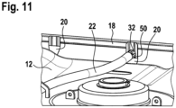
- FIG 11 Another perspective partial view of the top of the plastic inner container 12 with a central screw cap.
- the extended flattened area 50 of the vertical tubular rod 20 with the attached crossbar 22 becomes clear.
- the crossbars 22, (42) have a round or oval tubular profile with a diameter between 14 mm and 22 mm, preferably 16 mm, and a wall thickness between 0.7 mm and 1.2 mm, preferably 0.8 mm.
- the two ends of the cross members 22, 42 are screwed to the top horizontal tube 18 or to four vertical tubes 20 of the tubular lattice frame but can be removed again for the purpose of replacing the plastic inner container 12.
- the various curved versions of the crossbars 22, 42 as spring elements enable different designs of attachment with horizontal or vertical screwing of the two ends of the crossbars 22, 42 on the upper tubular lattice frame 14.
- the described embodiments of the crossbeams and the fastening options can easily be combined with one another and interchanged with one another.
Landscapes
- Engineering & Computer Science (AREA)
- Mechanical Engineering (AREA)
- Pallets (AREA)
- Packages (AREA)
- Auxiliary Devices For And Details Of Packaging Control (AREA)
Applications Claiming Priority (3)
| Application Number | Priority Date | Filing Date | Title |
|---|---|---|---|
| DE202019004316 | 2019-10-18 | ||
| DE202019004962 | 2019-12-05 | ||
| PCT/EP2020/000178 WO2021073766A1 (de) | 2019-10-18 | 2020-10-16 | Palettencontainer |
Publications (2)
| Publication Number | Publication Date |
|---|---|
| EP4045429A1 EP4045429A1 (de) | 2022-08-24 |
| EP4045429B1 true EP4045429B1 (de) | 2023-06-07 |
Family
ID=73172642
Family Applications (2)
| Application Number | Title | Priority Date | Filing Date |
|---|---|---|---|
| EP20803439.7A Active EP4045429B1 (de) | 2019-10-18 | 2020-10-16 | Palettencontainer |
| EP20803440.5A Active EP4045430B8 (de) | 2019-10-18 | 2020-10-16 | Palettencontainer |
Family Applications After (1)
| Application Number | Title | Priority Date | Filing Date |
|---|---|---|---|
| EP20803440.5A Active EP4045430B8 (de) | 2019-10-18 | 2020-10-16 | Palettencontainer |
Country Status (14)
| Country | Link |
|---|---|
| US (3) | US12187517B2 (pl) |
| EP (2) | EP4045429B1 (pl) |
| JP (3) | JP7629009B2 (pl) |
| KR (2) | KR20220084143A (pl) |
| CN (3) | CN119527713A (pl) |
| AU (2) | AU2020367194B2 (pl) |
| BR (2) | BR112022006301A2 (pl) |
| CA (2) | CA3153751A1 (pl) |
| ES (2) | ES2956513T3 (pl) |
| IL (3) | IL292154B1 (pl) |
| MX (3) | MX2022004447A (pl) |
| PL (2) | PL4045429T3 (pl) |
| WO (2) | WO2021073766A1 (pl) |
| ZA (2) | ZA202204421B (pl) |
Families Citing this family (4)
| Publication number | Priority date | Publication date | Assignee | Title |
|---|---|---|---|---|
| DE102020127721A1 (de) * | 2020-10-21 | 2022-04-21 | Protechna S.A. | Transport- und Lagerbehälter für Flüssigkeiten |
| USD1112596S1 (en) | 2024-01-11 | 2026-02-10 | Genesis Systems Llc | Water generator housing |
| USD1112595S1 (en) * | 2024-01-11 | 2026-02-10 | Genesis Systems Llc | Water generator housing |
| KR102715755B1 (ko) | 2024-02-19 | 2024-10-11 | (주)위아클 | 고청정도 클린용기 제조방법 및 이에 의해 제조된 고청정도 클린용기 |
Family Cites Families (18)
| Publication number | Priority date | Publication date | Assignee | Title |
|---|---|---|---|---|
| DE9202045U1 (de) | 1992-02-18 | 1992-09-17 | Mauser-Werke GmbH, 5040 Brühl | Palettencontainer |
| DE4425630C2 (de) * | 1994-04-15 | 1996-09-05 | Protechna Sa | Transport- und Lagerbehälter für Flüssigkeiten |
| DE19535707A1 (de) * | 1995-09-26 | 1997-03-27 | Protechna Sa | Palettenbehälter |
| KR20030015251A (ko) * | 2000-05-25 | 2003-02-20 | 마우저-베르케 게엠베하 운트 코. 카게 | 팔레트 컨테이너 |
| DE10103656A1 (de) * | 2000-05-25 | 2001-12-06 | Mauser Werke Gmbh & Co Kg | Palettencontainer |
| DE10252745B3 (de) * | 2002-11-13 | 2004-06-17 | Schütz GmbH & Co. KGaA | Lagerbehälter für Flüssigkeiten und Verfahren zur Herstellung des Außenbehälters des Lagerbehälters |
| DE10301517B3 (de) * | 2003-01-17 | 2004-03-11 | Protechna S.A. | Transport- und Lagerbehälter für Flüssigkeiten |
| DE502004000779D1 (de) * | 2003-04-25 | 2006-07-27 | Mauser Werke Gmbh & Co Kg | Palettencontainer |
| WO2012085938A1 (en) * | 2010-12-24 | 2012-06-28 | Genex Science And Technologies Pvt. Ltd. | Pallet container with improved top lifting performance |
| WO2012085940A2 (en) | 2010-12-24 | 2012-06-28 | Genex Science And Technologies Pvt. Ltd. | Pallet container with riveted cage |
| DE102011087927B4 (de) * | 2011-12-07 | 2018-06-21 | Protechna S.A. | Transport- und Lagerbehälter für Flüssigkeiten |
| DE202013000624U1 (de) * | 2012-09-21 | 2013-03-07 | Mauser-Werke Gmbh | Palettencontainer |
| DE102013213167A1 (de) * | 2013-07-04 | 2015-01-22 | Protechna S.A. | Innenbehälter aus Kunststoff sowie Transport- und Lagerbehälter für Flüssigkeiten mit einem derartigen Innenbehälter |
| FR3037931A1 (fr) * | 2015-06-26 | 2016-12-30 | Sotralentz Packaging | Conteneur a palette empilable muni d'une armature superieure de renfort |
| CA2995272C (en) | 2015-08-12 | 2023-10-03 | Shuttle Gauge Ip Pty Ltd | Volume measurement apparatus |
| DE102015016814A1 (de) * | 2015-12-23 | 2017-06-29 | Protechna S.A. | Transport- und Lagerbehälter für Flüssigkeiten |
| DE102016000072B4 (de) | 2016-01-07 | 2018-11-29 | Mauser-Werke Gmbh | Palettencontainer |
| HRP20211522T1 (hr) * | 2016-09-12 | 2021-12-24 | Mauser-Werke Gmbh | Paletni spremnik |
-
2020
- 2020-10-16 PL PL20803439.7T patent/PL4045429T3/pl unknown
- 2020-10-16 CA CA3153751A patent/CA3153751A1/en active Pending
- 2020-10-16 CA CA3153773A patent/CA3153773A1/en active Pending
- 2020-10-16 US US17/768,739 patent/US12187517B2/en active Active
- 2020-10-16 CN CN202411299434.6A patent/CN119527713A/zh active Pending
- 2020-10-16 BR BR112022006301A patent/BR112022006301A2/pt active IP Right Grant
- 2020-10-16 ES ES20803440T patent/ES2956513T3/es active Active
- 2020-10-16 BR BR112022006277A patent/BR112022006277A2/pt active Search and Examination
- 2020-10-16 JP JP2022522899A patent/JP7629009B2/ja active Active
- 2020-10-16 AU AU2020367194A patent/AU2020367194B2/en active Active
- 2020-10-16 US US17/769,538 patent/US12172818B2/en active Active
- 2020-10-16 MX MX2022004447A patent/MX2022004447A/es unknown
- 2020-10-16 CN CN202080072042.XA patent/CN114514184B/zh active Active
- 2020-10-16 WO PCT/EP2020/000178 patent/WO2021073766A1/de not_active Ceased
- 2020-10-16 AU AU2020365203A patent/AU2020365203B2/en active Active
- 2020-10-16 KR KR1020227016573A patent/KR20220084143A/ko not_active Withdrawn
- 2020-10-16 CN CN202080072003.XA patent/CN114514183B/zh active Active
- 2020-10-16 IL IL292154A patent/IL292154B1/en unknown
- 2020-10-16 EP EP20803439.7A patent/EP4045429B1/de active Active
- 2020-10-16 IL IL292241A patent/IL292241B2/en unknown
- 2020-10-16 MX MX2022004448A patent/MX2022004448A/es unknown
- 2020-10-16 EP EP20803440.5A patent/EP4045430B8/de active Active
- 2020-10-16 ES ES20803439T patent/ES2955336T3/es active Active
- 2020-10-16 WO PCT/EP2020/000179 patent/WO2021073767A1/de not_active Ceased
- 2020-10-16 PL PL20803440.5T patent/PL4045430T3/pl unknown
- 2020-10-16 KR KR1020227016574A patent/KR20220084360A/ko not_active Withdrawn
- 2020-10-16 JP JP2022522898A patent/JP7630504B2/ja active Active
-
2022
- 2022-04-12 MX MX2025008325A patent/MX2025008325A/es unknown
- 2022-04-20 ZA ZA2022/04421A patent/ZA202204421B/en unknown
- 2022-04-20 ZA ZA2022/04426A patent/ZA202204426B/en unknown
-
2024
- 2024-11-18 US US18/951,409 patent/US20250074682A1/en active Pending
-
2025
- 2025-02-04 JP JP2025016887A patent/JP2025069357A/ja active Pending
- 2025-11-04 IL IL324436A patent/IL324436A/en unknown
Also Published As
Similar Documents
| Publication | Publication Date | Title |
|---|---|---|
| EP4045429B1 (de) | Palettencontainer | |
| EP0694016B1 (de) | Palettencontainer | |
| DE69002918T2 (de) | Tankcontainer. | |
| EP2340217B1 (de) | Palettencontainer | |
| EP3575238B1 (de) | Palettencontainer | |
| EP2426067A1 (de) | Transport- und Lagerbehälter für Flüssigkeiten | |
| WO2018046131A1 (de) | Palettencontainer | |
| EP3880570A1 (de) | Kunststoffpalette mit geschützten kufen | |
| EP1754670B1 (de) | Transport- und Lagerbehälter für Flüssigkeiten | |
| EP1289852A1 (de) | Palettencontainer | |
| DE102019008477B4 (de) | Palettencontainer | |
| DE112004000700B4 (de) | Palettencontainer mit gekreuzten Rohrstäben | |
| DE19836378C2 (de) | Palette | |
| DE102019007360A1 (de) | Palettencontainer | |
| DE10002610B4 (de) | Container für Flüssigkeiten und fließfähige Produkte | |
| EP3256401B1 (de) | Palettenartiges untergestell für transport- und lagerbehälter für flüssigkeiten | |
| EP3790815B1 (de) | Transport- und lagerbehälter für flüssigkeiten | |
| EP3608247B1 (de) | Kanister | |
| EP1354825B1 (de) | Müllbehälter mit verstärkter Zapfen-Einheit | |
| DE102016010889A1 (de) | Palettencontainer | |
| EP2143652B1 (de) | Stapelbarer Lager- und Transportbehälter | |
| EP4087789B1 (de) | Transportbügel für einen gitterrost | |
| DE2454606B2 (de) | Container fuer koerniges und staubfoermiges gut | |
| AT10330U1 (de) | Verpackung | |
| DE29608417U1 (de) | Stapelbarer Kunststoffbehälter für die Lagerung und den Transport von Gutstücken, insbesondere Käselaiben |
Legal Events
| Date | Code | Title | Description |
|---|---|---|---|
| STAA | Information on the status of an ep patent application or granted ep patent |
Free format text: STATUS: UNKNOWN |
|
| STAA | Information on the status of an ep patent application or granted ep patent |
Free format text: STATUS: THE INTERNATIONAL PUBLICATION HAS BEEN MADE |
|
| PUAI | Public reference made under article 153(3) epc to a published international application that has entered the european phase |
Free format text: ORIGINAL CODE: 0009012 |
|
| STAA | Information on the status of an ep patent application or granted ep patent |
Free format text: STATUS: REQUEST FOR EXAMINATION WAS MADE |
|
| 17P | Request for examination filed |
Effective date: 20220518 |
|
| AK | Designated contracting states |
Kind code of ref document: A1 Designated state(s): AL AT BE BG CH CY CZ DE DK EE ES FI FR GB GR HR HU IE IS IT LI LT LU LV MC MK MT NL NO PL PT RO RS SE SI SK SM TR |
|
| GRAP | Despatch of communication of intention to grant a patent |
Free format text: ORIGINAL CODE: EPIDOSNIGR1 |
|
| STAA | Information on the status of an ep patent application or granted ep patent |
Free format text: STATUS: GRANT OF PATENT IS INTENDED |
|
| DAV | Request for validation of the european patent (deleted) | ||
| DAX | Request for extension of the european patent (deleted) | ||
| INTG | Intention to grant announced |
Effective date: 20230105 |
|
| GRAS | Grant fee paid |
Free format text: ORIGINAL CODE: EPIDOSNIGR3 |
|
| GRAA | (expected) grant |
Free format text: ORIGINAL CODE: 0009210 |
|
| STAA | Information on the status of an ep patent application or granted ep patent |
Free format text: STATUS: THE PATENT HAS BEEN GRANTED |
|
| AK | Designated contracting states |
Kind code of ref document: B1 Designated state(s): AL AT BE BG CH CY CZ DE DK EE ES FI FR GB GR HR HU IE IS IT LI LT LU LV MC MK MT NL NO PL PT RO RS SE SI SK SM TR |
|
| REG | Reference to a national code |
Ref country code: GB Ref legal event code: FG4D Free format text: NOT ENGLISH |
|
| REG | Reference to a national code |
Ref country code: CH Ref legal event code: EP Ref country code: AT Ref legal event code: REF Ref document number: 1574382 Country of ref document: AT Kind code of ref document: T Effective date: 20230615 |
|
| REG | Reference to a national code |
Ref country code: DE Ref legal event code: R096 Ref document number: 502020003739 Country of ref document: DE |
|
| P01 | Opt-out of the competence of the unified patent court (upc) registered |
Effective date: 20230602 |
|
| REG | Reference to a national code |
Ref country code: NO Ref legal event code: T2 Effective date: 20230607 |
|
| REG | Reference to a national code |
Ref country code: NL Ref legal event code: FP |
|
| REG | Reference to a national code |
Ref country code: LT Ref legal event code: MG9D |
|
| REG | Reference to a national code |
Ref country code: SE Ref legal event code: TRGR |
|
| PG25 | Lapsed in a contracting state [announced via postgrant information from national office to epo] |
Ref country code: RS Free format text: LAPSE BECAUSE OF FAILURE TO SUBMIT A TRANSLATION OF THE DESCRIPTION OR TO PAY THE FEE WITHIN THE PRESCRIBED TIME-LIMIT Effective date: 20230607 Ref country code: LV Free format text: LAPSE BECAUSE OF FAILURE TO SUBMIT A TRANSLATION OF THE DESCRIPTION OR TO PAY THE FEE WITHIN THE PRESCRIBED TIME-LIMIT Effective date: 20230607 Ref country code: LT Free format text: LAPSE BECAUSE OF FAILURE TO SUBMIT A TRANSLATION OF THE DESCRIPTION OR TO PAY THE FEE WITHIN THE PRESCRIBED TIME-LIMIT Effective date: 20230607 Ref country code: HR Free format text: LAPSE BECAUSE OF FAILURE TO SUBMIT A TRANSLATION OF THE DESCRIPTION OR TO PAY THE FEE WITHIN THE PRESCRIBED TIME-LIMIT Effective date: 20230607 Ref country code: GR Free format text: LAPSE BECAUSE OF FAILURE TO SUBMIT A TRANSLATION OF THE DESCRIPTION OR TO PAY THE FEE WITHIN THE PRESCRIBED TIME-LIMIT Effective date: 20230908 |
|
| REG | Reference to a national code |
Ref country code: ES Ref legal event code: FG2A Ref document number: 2955336 Country of ref document: ES Kind code of ref document: T3 Effective date: 20231130 |
|
| PG25 | Lapsed in a contracting state [announced via postgrant information from national office to epo] |
Ref country code: FI Free format text: LAPSE BECAUSE OF FAILURE TO SUBMIT A TRANSLATION OF THE DESCRIPTION OR TO PAY THE FEE WITHIN THE PRESCRIBED TIME-LIMIT Effective date: 20230607 |
|
| PG25 | Lapsed in a contracting state [announced via postgrant information from national office to epo] |
Ref country code: SK Free format text: LAPSE BECAUSE OF FAILURE TO SUBMIT A TRANSLATION OF THE DESCRIPTION OR TO PAY THE FEE WITHIN THE PRESCRIBED TIME-LIMIT Effective date: 20230607 |
|
| PG25 | Lapsed in a contracting state [announced via postgrant information from national office to epo] |
Ref country code: IS Free format text: LAPSE BECAUSE OF FAILURE TO SUBMIT A TRANSLATION OF THE DESCRIPTION OR TO PAY THE FEE WITHIN THE PRESCRIBED TIME-LIMIT Effective date: 20231007 |
|
| PG25 | Lapsed in a contracting state [announced via postgrant information from national office to epo] |
Ref country code: SM Free format text: LAPSE BECAUSE OF FAILURE TO SUBMIT A TRANSLATION OF THE DESCRIPTION OR TO PAY THE FEE WITHIN THE PRESCRIBED TIME-LIMIT Effective date: 20230607 Ref country code: SK Free format text: LAPSE BECAUSE OF FAILURE TO SUBMIT A TRANSLATION OF THE DESCRIPTION OR TO PAY THE FEE WITHIN THE PRESCRIBED TIME-LIMIT Effective date: 20230607 Ref country code: RO Free format text: LAPSE BECAUSE OF FAILURE TO SUBMIT A TRANSLATION OF THE DESCRIPTION OR TO PAY THE FEE WITHIN THE PRESCRIBED TIME-LIMIT Effective date: 20230607 Ref country code: PT Free format text: LAPSE BECAUSE OF FAILURE TO SUBMIT A TRANSLATION OF THE DESCRIPTION OR TO PAY THE FEE WITHIN THE PRESCRIBED TIME-LIMIT Effective date: 20231009 Ref country code: IS Free format text: LAPSE BECAUSE OF FAILURE TO SUBMIT A TRANSLATION OF THE DESCRIPTION OR TO PAY THE FEE WITHIN THE PRESCRIBED TIME-LIMIT Effective date: 20231007 Ref country code: EE Free format text: LAPSE BECAUSE OF FAILURE TO SUBMIT A TRANSLATION OF THE DESCRIPTION OR TO PAY THE FEE WITHIN THE PRESCRIBED TIME-LIMIT Effective date: 20230607 Ref country code: CZ Free format text: LAPSE BECAUSE OF FAILURE TO SUBMIT A TRANSLATION OF THE DESCRIPTION OR TO PAY THE FEE WITHIN THE PRESCRIBED TIME-LIMIT Effective date: 20230607 |
|
| REG | Reference to a national code |
Ref country code: DE Ref legal event code: R097 Ref document number: 502020003739 Country of ref document: DE |
|
| PLBE | No opposition filed within time limit |
Free format text: ORIGINAL CODE: 0009261 |
|
| STAA | Information on the status of an ep patent application or granted ep patent |
Free format text: STATUS: NO OPPOSITION FILED WITHIN TIME LIMIT |
|
| PG25 | Lapsed in a contracting state [announced via postgrant information from national office to epo] |
Ref country code: DK Free format text: LAPSE BECAUSE OF FAILURE TO SUBMIT A TRANSLATION OF THE DESCRIPTION OR TO PAY THE FEE WITHIN THE PRESCRIBED TIME-LIMIT Effective date: 20230607 |
|
| PG25 | Lapsed in a contracting state [announced via postgrant information from national office to epo] |
Ref country code: SI Free format text: LAPSE BECAUSE OF FAILURE TO SUBMIT A TRANSLATION OF THE DESCRIPTION OR TO PAY THE FEE WITHIN THE PRESCRIBED TIME-LIMIT Effective date: 20230607 |
|
| 26N | No opposition filed |
Effective date: 20240308 |
|
| PG25 | Lapsed in a contracting state [announced via postgrant information from national office to epo] |
Ref country code: SI Free format text: LAPSE BECAUSE OF FAILURE TO SUBMIT A TRANSLATION OF THE DESCRIPTION OR TO PAY THE FEE WITHIN THE PRESCRIBED TIME-LIMIT Effective date: 20230607 Ref country code: MC Free format text: LAPSE BECAUSE OF FAILURE TO SUBMIT A TRANSLATION OF THE DESCRIPTION OR TO PAY THE FEE WITHIN THE PRESCRIBED TIME-LIMIT Effective date: 20230607 |
|
| PG25 | Lapsed in a contracting state [announced via postgrant information from national office to epo] |
Ref country code: LU Free format text: LAPSE BECAUSE OF NON-PAYMENT OF DUE FEES Effective date: 20231016 |
|
| PG25 | Lapsed in a contracting state [announced via postgrant information from national office to epo] |
Ref country code: LU Free format text: LAPSE BECAUSE OF NON-PAYMENT OF DUE FEES Effective date: 20231016 |
|
| PG25 | Lapsed in a contracting state [announced via postgrant information from national office to epo] |
Ref country code: BG Free format text: LAPSE BECAUSE OF FAILURE TO SUBMIT A TRANSLATION OF THE DESCRIPTION OR TO PAY THE FEE WITHIN THE PRESCRIBED TIME-LIMIT Effective date: 20230607 |
|
| PG25 | Lapsed in a contracting state [announced via postgrant information from national office to epo] |
Ref country code: BG Free format text: LAPSE BECAUSE OF FAILURE TO SUBMIT A TRANSLATION OF THE DESCRIPTION OR TO PAY THE FEE WITHIN THE PRESCRIBED TIME-LIMIT Effective date: 20230607 |
|
| REG | Reference to a national code |
Ref country code: DE Ref legal event code: R082 Ref document number: 502020003739 Country of ref document: DE Representative=s name: HOFFMANN EITLE PATENT- UND RECHTSANWAELTE PART, DE |
|
| PG25 | Lapsed in a contracting state [announced via postgrant information from national office to epo] |
Ref country code: CY Free format text: LAPSE BECAUSE OF FAILURE TO SUBMIT A TRANSLATION OF THE DESCRIPTION OR TO PAY THE FEE WITHIN THE PRESCRIBED TIME-LIMIT; INVALID AB INITIO Effective date: 20201016 |
|
| PG25 | Lapsed in a contracting state [announced via postgrant information from national office to epo] |
Ref country code: HU Free format text: LAPSE BECAUSE OF FAILURE TO SUBMIT A TRANSLATION OF THE DESCRIPTION OR TO PAY THE FEE WITHIN THE PRESCRIBED TIME-LIMIT; INVALID AB INITIO Effective date: 20201016 |
|
| REG | Reference to a national code |
Ref country code: CH Ref legal event code: U11 Free format text: ST27 STATUS EVENT CODE: U-0-0-U10-U11 (AS PROVIDED BY THE NATIONAL OFFICE) Effective date: 20251101 |
|
| PGFP | Annual fee paid to national office [announced via postgrant information from national office to epo] |
Ref country code: NL Payment date: 20251026 Year of fee payment: 6 |
|
| PGFP | Annual fee paid to national office [announced via postgrant information from national office to epo] |
Ref country code: DE Payment date: 20251029 Year of fee payment: 6 |
|
| PGFP | Annual fee paid to national office [announced via postgrant information from national office to epo] |
Ref country code: GB Payment date: 20251027 Year of fee payment: 6 |
|
| PGFP | Annual fee paid to national office [announced via postgrant information from national office to epo] |
Ref country code: NO Payment date: 20251029 Year of fee payment: 6 |
|
| PGFP | Annual fee paid to national office [announced via postgrant information from national office to epo] |
Ref country code: AT Payment date: 20251029 Year of fee payment: 6 |
|
| PGFP | Annual fee paid to national office [announced via postgrant information from national office to epo] |
Ref country code: IT Payment date: 20251021 Year of fee payment: 6 |
|
| PGFP | Annual fee paid to national office [announced via postgrant information from national office to epo] |
Ref country code: FR Payment date: 20251027 Year of fee payment: 6 |
|
| PGFP | Annual fee paid to national office [announced via postgrant information from national office to epo] |
Ref country code: TR Payment date: 20251007 Year of fee payment: 6 Ref country code: BE Payment date: 20251027 Year of fee payment: 6 |
|
| PGFP | Annual fee paid to national office [announced via postgrant information from national office to epo] |
Ref country code: SE Payment date: 20251027 Year of fee payment: 6 Ref country code: CH Payment date: 20251101 Year of fee payment: 6 |
|
| PGFP | Annual fee paid to national office [announced via postgrant information from national office to epo] |
Ref country code: IE Payment date: 20251027 Year of fee payment: 6 |
|
| PGFP | Annual fee paid to national office [announced via postgrant information from national office to epo] |
Ref country code: PL Payment date: 20251008 Year of fee payment: 6 |
|
| PGFP | Annual fee paid to national office [announced via postgrant information from national office to epo] |
Ref country code: ES Payment date: 20251103 Year of fee payment: 6 |