EP4045429B1 - Pallet container - Google Patents
Pallet container Download PDFInfo
- Publication number
- EP4045429B1 EP4045429B1 EP20803439.7A EP20803439A EP4045429B1 EP 4045429 B1 EP4045429 B1 EP 4045429B1 EP 20803439 A EP20803439 A EP 20803439A EP 4045429 B1 EP4045429 B1 EP 4045429B1
- Authority
- EP
- European Patent Office
- Prior art keywords
- members
- transverse cross
- screwed
- tubular
- pallet container
- Prior art date
- Legal status (The legal status is an assumption and is not a legal conclusion. Google has not performed a legal analysis and makes no representation as to the accuracy of the status listed.)
- Active
Links
- 239000004033 plastic Substances 0.000 claims description 22
- 229920003023 plastic Polymers 0.000 claims description 22
- 239000000463 material Substances 0.000 claims description 3
- 230000009969 flowable effect Effects 0.000 claims 1
- 239000012530 fluid Substances 0.000 claims 1
- 229920001169 thermoplastic Polymers 0.000 claims 1
- 208000027418 Wounds and injury Diseases 0.000 description 4
- 230000006378 damage Effects 0.000 description 4
- 208000014674 injury Diseases 0.000 description 4
- 230000000694 effects Effects 0.000 description 2
- 239000007788 liquid Substances 0.000 description 2
- 239000012815 thermoplastic material Substances 0.000 description 2
- 230000007704 transition Effects 0.000 description 2
- 208000034693 Laceration Diseases 0.000 description 1
- 238000010276 construction Methods 0.000 description 1
- 229920001903 high density polyethylene Polymers 0.000 description 1
- 239000004700 high-density polyethylene Substances 0.000 description 1
- 238000000034 method Methods 0.000 description 1
- 230000001681 protective effect Effects 0.000 description 1
- 230000035939 shock Effects 0.000 description 1
- 238000004904 shortening Methods 0.000 description 1
Images


Classifications
-
- B—PERFORMING OPERATIONS; TRANSPORTING
- B65—CONVEYING; PACKING; STORING; HANDLING THIN OR FILAMENTARY MATERIAL
- B65D—CONTAINERS FOR STORAGE OR TRANSPORT OF ARTICLES OR MATERIALS, e.g. BAGS, BARRELS, BOTTLES, BOXES, CANS, CARTONS, CRATES, DRUMS, JARS, TANKS, HOPPERS, FORWARDING CONTAINERS; ACCESSORIES, CLOSURES, OR FITTINGS THEREFOR; PACKAGING ELEMENTS; PACKAGES
- B65D77/00—Packages formed by enclosing articles or materials in preformed containers, e.g. boxes, cartons, sacks or bags
- B65D77/04—Articles or materials enclosed in two or more containers disposed one within another
- B65D77/0446—Articles or materials enclosed in two or more containers disposed one within another the inner and outer containers being rigid or semi-rigid and the outer container being of polygonal cross-section not formed by folding or erecting one or more blanks
- B65D77/0453—Articles or materials enclosed in two or more containers disposed one within another the inner and outer containers being rigid or semi-rigid and the outer container being of polygonal cross-section not formed by folding or erecting one or more blanks the inner container having a polygonal cross-section
- B65D77/0466—Articles or materials enclosed in two or more containers disposed one within another the inner and outer containers being rigid or semi-rigid and the outer container being of polygonal cross-section not formed by folding or erecting one or more blanks the inner container having a polygonal cross-section the containers being mounted on a pallet
-
- B—PERFORMING OPERATIONS; TRANSPORTING
- B65—CONVEYING; PACKING; STORING; HANDLING THIN OR FILAMENTARY MATERIAL
- B65D—CONTAINERS FOR STORAGE OR TRANSPORT OF ARTICLES OR MATERIALS, e.g. BAGS, BARRELS, BOTTLES, BOXES, CANS, CARTONS, CRATES, DRUMS, JARS, TANKS, HOPPERS, FORWARDING CONTAINERS; ACCESSORIES, CLOSURES, OR FITTINGS THEREFOR; PACKAGING ELEMENTS; PACKAGES
- B65D19/00—Pallets or like platforms, with or without side walls, for supporting loads to be lifted or lowered
- B65D19/02—Rigid pallets with side walls, e.g. box pallets
- B65D19/06—Rigid pallets with side walls, e.g. box pallets with bodies formed by uniting or interconnecting two or more components
- B65D19/08—Rigid pallets with side walls, e.g. box pallets with bodies formed by uniting or interconnecting two or more components made wholly or mainly of metal
- B65D19/10—Rigid pallets with side walls, e.g. box pallets with bodies formed by uniting or interconnecting two or more components made wholly or mainly of metal of skeleton construction, e.g. made of wire
-
- B—PERFORMING OPERATIONS; TRANSPORTING
- B65—CONVEYING; PACKING; STORING; HANDLING THIN OR FILAMENTARY MATERIAL
- B65D—CONTAINERS FOR STORAGE OR TRANSPORT OF ARTICLES OR MATERIALS, e.g. BAGS, BARRELS, BOTTLES, BOXES, CANS, CARTONS, CRATES, DRUMS, JARS, TANKS, HOPPERS, FORWARDING CONTAINERS; ACCESSORIES, CLOSURES, OR FITTINGS THEREFOR; PACKAGING ELEMENTS; PACKAGES
- B65D19/00—Pallets or like platforms, with or without side walls, for supporting loads to be lifted or lowered
- B65D19/02—Rigid pallets with side walls, e.g. box pallets
- B65D19/06—Rigid pallets with side walls, e.g. box pallets with bodies formed by uniting or interconnecting two or more components
- B65D19/18—Rigid pallets with side walls, e.g. box pallets with bodies formed by uniting or interconnecting two or more components made wholly or mainly of plastics material
-
- B—PERFORMING OPERATIONS; TRANSPORTING
- B65—CONVEYING; PACKING; STORING; HANDLING THIN OR FILAMENTARY MATERIAL
- B65D—CONTAINERS FOR STORAGE OR TRANSPORT OF ARTICLES OR MATERIALS, e.g. BAGS, BARRELS, BOTTLES, BOXES, CANS, CARTONS, CRATES, DRUMS, JARS, TANKS, HOPPERS, FORWARDING CONTAINERS; ACCESSORIES, CLOSURES, OR FITTINGS THEREFOR; PACKAGING ELEMENTS; PACKAGES
- B65D19/00—Pallets or like platforms, with or without side walls, for supporting loads to be lifted or lowered
- B65D19/38—Details or accessories
- B65D19/385—Frames, corner posts or pallet converters, e.g. for facilitating stacking of charged pallets
-
- B—PERFORMING OPERATIONS; TRANSPORTING
- B65—CONVEYING; PACKING; STORING; HANDLING THIN OR FILAMENTARY MATERIAL
- B65D—CONTAINERS FOR STORAGE OR TRANSPORT OF ARTICLES OR MATERIALS, e.g. BAGS, BARRELS, BOTTLES, BOXES, CANS, CARTONS, CRATES, DRUMS, JARS, TANKS, HOPPERS, FORWARDING CONTAINERS; ACCESSORIES, CLOSURES, OR FITTINGS THEREFOR; PACKAGING ELEMENTS; PACKAGES
- B65D19/00—Pallets or like platforms, with or without side walls, for supporting loads to be lifted or lowered
- B65D19/38—Details or accessories
- B65D19/44—Elements or devices for locating articles on platforms
-
- B—PERFORMING OPERATIONS; TRANSPORTING
- B65—CONVEYING; PACKING; STORING; HANDLING THIN OR FILAMENTARY MATERIAL
- B65D—CONTAINERS FOR STORAGE OR TRANSPORT OF ARTICLES OR MATERIALS, e.g. BAGS, BARRELS, BOTTLES, BOXES, CANS, CARTONS, CRATES, DRUMS, JARS, TANKS, HOPPERS, FORWARDING CONTAINERS; ACCESSORIES, CLOSURES, OR FITTINGS THEREFOR; PACKAGING ELEMENTS; PACKAGES
- B65D2519/00—Pallets or like platforms, with or without side walls, for supporting loads to be lifted or lowered
- B65D2519/00004—Details relating to pallets
- B65D2519/00009—Materials
- B65D2519/00154—Materials for the side walls
- B65D2519/00164—Metal
-
- B—PERFORMING OPERATIONS; TRANSPORTING
- B65—CONVEYING; PACKING; STORING; HANDLING THIN OR FILAMENTARY MATERIAL
- B65D—CONTAINERS FOR STORAGE OR TRANSPORT OF ARTICLES OR MATERIALS, e.g. BAGS, BARRELS, BOTTLES, BOXES, CANS, CARTONS, CRATES, DRUMS, JARS, TANKS, HOPPERS, FORWARDING CONTAINERS; ACCESSORIES, CLOSURES, OR FITTINGS THEREFOR; PACKAGING ELEMENTS; PACKAGES
- B65D2519/00—Pallets or like platforms, with or without side walls, for supporting loads to be lifted or lowered
- B65D2519/00004—Details relating to pallets
- B65D2519/00258—Overall construction
- B65D2519/00492—Overall construction of the side walls
- B65D2519/00512—Overall construction of the side walls skeleton type
-
- B—PERFORMING OPERATIONS; TRANSPORTING
- B65—CONVEYING; PACKING; STORING; HANDLING THIN OR FILAMENTARY MATERIAL
- B65D—CONTAINERS FOR STORAGE OR TRANSPORT OF ARTICLES OR MATERIALS, e.g. BAGS, BARRELS, BOTTLES, BOXES, CANS, CARTONS, CRATES, DRUMS, JARS, TANKS, HOPPERS, FORWARDING CONTAINERS; ACCESSORIES, CLOSURES, OR FITTINGS THEREFOR; PACKAGING ELEMENTS; PACKAGES
- B65D2519/00—Pallets or like platforms, with or without side walls, for supporting loads to be lifted or lowered
- B65D2519/00004—Details relating to pallets
- B65D2519/00258—Overall construction
- B65D2519/00492—Overall construction of the side walls
- B65D2519/00532—Frame structures
-
- B—PERFORMING OPERATIONS; TRANSPORTING
- B65—CONVEYING; PACKING; STORING; HANDLING THIN OR FILAMENTARY MATERIAL
- B65D—CONTAINERS FOR STORAGE OR TRANSPORT OF ARTICLES OR MATERIALS, e.g. BAGS, BARRELS, BOTTLES, BOXES, CANS, CARTONS, CRATES, DRUMS, JARS, TANKS, HOPPERS, FORWARDING CONTAINERS; ACCESSORIES, CLOSURES, OR FITTINGS THEREFOR; PACKAGING ELEMENTS; PACKAGES
- B65D2519/00—Pallets or like platforms, with or without side walls, for supporting loads to be lifted or lowered
- B65D2519/00004—Details relating to pallets
- B65D2519/00547—Connections
Description
Die vorliegende Erfindung bezieht sich auf einen Palettencontainer zur Lagerung und zum Transport von flüssigen oder fließfähigen Füllgütern mit einem dünnwandigen starren Innenbehälter aus thermoplastischem Kunststoff, mit einem den Kunststoff-Innenbehälter als Stützmantel dicht umschließenden Rohr-Gitterrahmen aus miteinander verschweißten horizontalen und vertikalen Rohrstäben, und mit einer Bodenpalette, auf welcher der Kunststoff-Innenbehälter aufliegt und mit welcher der Rohr-Gitterrahmen fest verbunden ist, wobei oberhalb des Kunststoff-Innenbehälters zwei stabförmige Quertraversen vorgesehen sind, die mit ihren beiden Enden über jeweils eine Verschraubung mittels Gewindeschrauben an zwei sich gegenüberliegenden Seitenwandungen im oberen Bereich des Rohr-Gitterrahmens befestigt sind,The present invention relates to a pallet container for storing and transporting liquid or free-flowing goods with a thin-walled rigid inner container made of thermoplastic material, with a tubular lattice frame tightly enclosing the plastic inner container as a supporting jacket and made of horizontal and vertical tubular bars welded together, and with a floor pallet on which the plastic inner container rests and to which the tubular lattice frame is firmly connected, with two rod-shaped crossbars being provided above the plastic inner container, which are connected at both ends via a screw connection using threaded screws on two opposite side walls in the upper area of the tubular trellis frame,
Die stabförmigen Quertraversen sollen ein übermäßiges Ausbeulen des Kunststoff-Innenbehälters bzw. seines Oberbodens mit zentraler Schraubkappe insbesondere bei Transporterschütterungen und dynamischen Schwingungen verhindern und dienen unter anderem auch dazu, im Falle eines ungewollten Umkippens des Palettencontainers den Kunststoff-Innenbehälter im Rohr-Gitterrahmen auf der Bodenpalette zu halten und ein Herausrutschen aus dem Rohr-Gitterrahmen zu verhindern. Um ein einfaches Auswechseln des Kunststoff-Innenbehälters für eine Mehrfachverwendung des Palettencontainers zu ermöglichen, sind die Quertraversen mit ihren beiden Enden lösbar im oberen Bereich des Rohr-Gitterrahmens befestigt, in aller Regel verschraubt.The rod-shaped crossbeams are intended to prevent excessive bulging of the plastic inner container or its top floor with a central screw cap, especially in the event of transport shocks and dynamic vibrations, and also serve, among other things, to secure the plastic inner container in the tubular lattice frame on the floor pallet in the event of the pallet container accidentally tipping over and to prevent it from slipping out of the tubular lattice frame. To enable easy replacement of the plastic inner container for multiple use of the pallet container, the crossbars are detachably attached at both ends in the upper area of the tubular lattice frame, usually screwed.
Ein derartiger Palettencontainer mit zwei parallel verlaufenden Quertraversen ist z. B. aus der Veröffentlichung
Befüllte Palettencontainer mit einem Gesamtgewicht von oftmals über 1 t werden z. B. bei der Abladung aus einem LKW oder bei der Einlagerung in ein Hochregallager mittels Gabelstapler-Fahrzeugen gehandhabt. Wenn Palettencontainer nur über kurze Wege, z. B. von einer Lagerhalle zu einer Entleerungsstation bzw. dem Einsatzort des Füllgutes transportiert werden sollen, dann werden oftmals auch Hubwagen verwendet. Leere Palettencontainer werden aber häufig auch von Hand manipuliert, so z. B. gekippt oder ein Stück gezogen. Dabei wird der Palettencontainer immer im oberen Bereich des Rohr-Gitterrahmens und insbesondere an dem obersten horizontal umlaufenden Rohrstab mit den Fingern bzw. von Hand angefasst. Sehr häufig werden dabei die Enden der Quertraversen und deren Verschraubungen mit angefasst. Die Enden der Quertraversen sind üblicherweise flachgedrückt, einmal um den obersten horizontal umlaufenden Rohrstab gelegt und darunter gegen sich selbst verschraubt. Dabei weisen die Enden der Quertraversen in aller Regel scharfkantige Stanzkanten auf und auch die frei nach innen hervorstehenden Enden der Gewindeschrauben werden häufig übersehen. Dies kann - selbst beim Tragen von Schutzhandschuhen - in nachteiliger Weise zu üblen Schnittverletzungen oder Fleischwunden führen.Filled pallet containers with a total weight of often more than 1 t are z. B. handled when unloading from a truck or when storing in a high-bay warehouse using forklift vehicles. If pallet containers only travel short distances, e.g. B. from a warehouse to an emptying station or the place of use of the filling material are to be transported, then pallet trucks are often used. However, empty pallet containers are also often manipulated by hand, e.g. B. tilted or pulled a piece. In doing so, the pallet container is always gripped with the fingers or by hand in the upper area of the tubular lattice frame and in particular on the topmost horizontal tubular bar. Very often, the ends of the crossbeams and their screw connections are also touched. The ends of the crossbeams are usually flattened, placed once around the topmost horizontal tubular bar and screwed against themselves underneath. The ends of the crossbeams usually have sharp-edged punched edges and the ends of the threaded screws that protrude inward are often overlooked. This can - even when wearing protective gloves - disadvantageously lead to severe cuts or lacerations.
Demzufolge ist es ist Aufgabe der vorliegenden Erfindung, die Handhabung von derartigen Palettencontainern mit manuellem Anfassen im oberen Bereich des Rohr-Gitterrahmens sicherer zu gestalten und mögliche Verletzungsgefahren zu vermindern.Accordingly, it is the object of the present invention to make the handling of such pallet containers with manual gripping in the upper area of the tubular lattice frame safer and to reduce possible risks of injury.
Die beabsichtigte Verminderung von Verletzungsgefahren wird auf sichere Weise dadurch erreicht, dass die Quertraversen in ihren Befestigungspunkten stirnseitig mit ihren beiden Enden gegen zwei sich gegenüberliegende Rohrstäbe im oberen Bereich des Rohr-Gitterrahmens verschraubt sind und die Gewindeschrauben axial in die mit einem Innengewinde versehenen Enden der Quertraversen einmünden.The intended reduction in the risk of injury is achieved in a safe manner by the fact that the crossbars are screwed at their attachment points at both ends to two opposite tubular bars in the upper area of the tubular lattice frame and the threaded screws are axially screwed into the ends of the crossbars that are provided with an internal thread flow in.
Durch diese erfindungsgemäße konstruktive Ausgestaltung der Quertraversenbefestigung mit axialer Einmündung der Gewindeschrauben in die Enden der Quertraversen wird bewirkt, dass die Verschraubungen der Quertraversen völlig verdeckt ausgebildet sind und keine freien Enden der Gewindeschrauben aus den Bauteilen herausragen können.This inventive structural design of the crossbar attachment with axial confluence of the threaded screws in the ends of the crossbars has the effect that the screw connections of the crossbars are designed to be completely covered and no free ends of the threaded screws can protrude from the components.
In Ausgestaltung der Erfindung ist vorgesehen, dass in die beiden Enden einer jeden Quertraverse mit Hohlrohrprofil jeweils eine Schraubmutter mit Innengewinde unlösbar fest eingesetzt ist und die Quertraversen mittels der stirnseitig eingedrehten Gewindeschrauben fest aber wieder lösbar an einem oberen horizontalen oder vertikalen Rohrstab des Rohr-Gitterrahmens angeschraubt sind. Die fest und unlösbar eingesetzte Schraubmutter kann einfach eingepresst, verquetscht oder eingeschweißt sein.In an embodiment of the invention it is provided that in each case a screw nut with an internal thread is permanently inserted into the two ends of each crossbeam with a hollow tube profile and the crossbeams are fixed but releasably to an upper horizontal or vertical by means of the threaded screws screwed into the front side tubular bar of the tubular lattice frame are screwed on. The screw nut, which is fixed and inseparable, can simply be pressed in, crimped or welded in.
Eine bevorzugte Ausgestaltung der Erfindung sieht vor, dass die jeweiligen Enden der Quertraversen stark eingequetscht sind und in diese Einquetschungen ein Innengewinde direkt eingeformt ist, wobei die Quertraversen mittels der stirnseitig eingedrehten Gewindeschrauben fest aber wieder lösbar an einem oberen horizontalen oder vertikalen Rohrstab des Rohr-Gitterrahmens angeschraubt sind.A preferred embodiment of the invention provides that the respective ends of the crossbeams are strongly pinched and an internal thread is formed directly in these pinched areas, with the crossbeams being fixed but detachable again to an upper horizontal or vertical tubular bar of the tubular lattice frame by means of the threaded screws screwed in at the front are screwed on.
Für diese Ausgestaltungsvarianten ist vorgehen, dass zwei benachbarte Enden der Quertraversen jeweils stirnseitig am oberen Ende von zwei benachbarten vertikalen Rohrstäben im flachgedrückten Bereich dicht unterhalb des obersten horizontal umlaufenden Rohrstabs angeschraubt sind.For these design variants, the procedure is that two adjacent ends of the crossbeams are each screwed to the front of the upper end of two adjacent vertical tubular bars in the flattened area just below the uppermost horizontally encircling tubular bar.
Dabei sind die beiden Enden der Quertraversen im vollkommen flachgedrückten Bereich der vertikalen Rohrstäbe angeschraubt. Um für die Enden der Quertraversen eine ebene Kontaktstelle zu schaffen, sind die flachgedrückten Bereiche der vertikalen Rohrstäbe für die angeschraubten Quertraversen verlängert flachgedrückt ausgebildet und damit länger als die flachgedrückten Bereiche der übrigen vertikalen Rohrstäbe.The two ends of the crossbeams are screwed on in the completely flattened area of the vertical tubular bars. In order to create a level contact point for the ends of the crossbars, the flattened areas of the vertical tubular bars for the screwed-on crossbars are designed to be flattened longer and thus longer than the flattened areas of the other vertical tubular bars.
In besonderer Ausgestaltung der Erfindung sind die Quertraversen als elastische Federelemente ausgebildet, wobei sie zwischen ihren beiden Befestigungspunkten nicht linear, sondern bogenförmig verlaufend ausgebildet sind und einen oder mehrere bogenförmige Abschnitte aufweisen.In a particular embodiment of the invention, the crossbeams are designed as elastic spring elements, whereby they are not designed to run linearly between their two attachment points, but rather in an arc shape and have one or more arcuate sections.
Bei einer bevorzugten Ausführungsform weisen die im vollkommen flachgedrückten Bereich der vertikalen Rohrstäbe angeschraubten Quertraversen jeweils einen vergleichsweise großen in Horizontalebene gebogenen Bogen auf, wobei die bogenförmig geschwungenen Quertraversen flach auf dem Oberboden des Kunststoff-Innenbehälters aufliegen und die großen Bögen der beiden Quertraversen voneinander weg weisend ausgerichtet sind.In a preferred embodiment, the crossbars screwed on in the completely flattened area of the vertical tubular rods each have a comparatively large arc curved in the horizontal plane, with the arched crossbars lying flat on the top of the plastic inner container and the large arcs of the two crossbars pointing away from each other are.
In abgewandelter Ausführungsform ist vorgesehen, dass die Quertraversen zwischen ihren beiden Befestigungspunkten nicht linear ausgebildet, sondern an ihren beiden Enden jeweils mit einem kleinen nach unten ausgeformten Bogen versehen sind, und jeweils stirnseitig von unten gegen den obersten umlaufenden horizontalen Rohrstab anstoßend festgeschraubt sind.In a modified embodiment, it is provided that the crossbars are not linear between their two attachment points, but are each provided with a small downwardly shaped arc at both ends, and are screwed tight at the front from below against the uppermost circumferential horizontal tubular bar.
Die als elastische Federelemente ausgebildeten Quertraversen können als stabförmige Hohlrohre mit einem rechteckförmigen, einem quadratischen, einem ovalen oder einem runden Rohrprofil ausgebildet sein, wobei die Länge der stirnseitig verschraubten Quertraversen zwischen ihren beiden Befestigungspunkten größer ausgebildet ist als der direkte Abstand zwischen den beiden Befestigungspunkten der Quertraversen.The crossbeams designed as elastic spring elements can be designed as rod-shaped hollow tubes with a rectangular, square, oval or round tube profile, with the length of the crossbeams bolted to the front side between their two attachment points being greater than the direct distance between the two attachment points of the crossbeams .
Durch die zweckmäßige Gestaltungsweise der beiden Quertraversen mit bogenförmig geschwungener Form als Verbindung der beiden gegenüberliegenden langen Seitenwandungen des Rohr-Gitterrahmens werden demzufolge die im oberen Bereich des Rohr-Gitterrahmens auftretenden Zugkräfte durch die als elastische Federelemente ausgebildeten Quertraversen erheblich abgemildert und die Belastungen auf die Befestigungspunkte bzw. Verschraubungen der Quertraversen spürbar verringert.Due to the expedient design of the two crossbeams with an arched shape as a connection of the two opposite long side walls of the tubular lattice frame, the tensile forces occurring in the upper area of the tubular lattice frame are significantly reduced by the crossbeams designed as elastic spring elements and the loads on the attachment points or The screw connections of the crossbeams noticeably reduced.
Bei einer Vibrationsprüfung fungiert die bogenförmig geschwungene Quertraverse wie eine elastische Feder. Während der Vibration schwingt der Oberboden des Innenbehälters nach oben und unten. Diese Schwingungen bewirken in ihren oberen und unteren Endpunkten eine elastische Biegung der bisher üblichen geraden Quertraversen nach oben und unten, die direkt in eine Abstandsverkürzung zwischen den Befestigungspunkten umgesetzt wird. Durch diese Abstandsverkürzung wird der Rohr-Gitterrahmen im oberen Bereich bei jedem Hub signifikant nach innen gezogen. Mit der neuen auch in Längsrichtung nachgiebigen "Feder-Lösung" wird dagegen am oberen Rand des Rohr-Gitterrahmens eine deutlich reduzierte Verformung und damit eine reduzierte Belastung der Bauteile des Palettencontainers erzielt.During a vibration test, the arched crossbeam acts like an elastic spring. During the vibration, the top floor of the inner container vibrates up and down. At their upper and lower end points, these vibrations cause the straight crossbeams that have been customary up to now to bend elastically upwards and downwards, which is directly translated into a shortening of the distance between the attachment points. Due to this reduction in distance, the tubular lattice frame is pulled significantly inwards in the upper area with each lift. With the new "spring solution", which is also flexible in the longitudinal direction, a significantly reduced deformation and thus a reduced load on the components of the pallet container is achieved at the upper edge of the tubular lattice frame.
Die Erfindung wird nachfolgend anhand von in den Zeichnungen schematisch dargestellten Ausführungsbeispielen näher erläutert und beschrieben. Es zeigen:
- Figur 1
- in perspektivischer Ansicht einen erfindungsgemäßen Palettencontainer,
- Figur 2
- eine vergrößerte Teil-Ansicht auf den oberen Bereich des erfindungsgemäßen Palettencontainers gemäß
Figur 1 , - Figur 3
- eine Draufsicht auf eine als Federelement ausgebildete Quertraverse,
- Figur 4
- eine Seitenansicht auf eine andere Ausführungsform einer Quertraverse,
- Figur 5
- in vergrößerter Teil-Ansicht den rechten Endbereich einer Quertraverse mit eingesetzter Schraubmutter,
- Figur 6
- eine vergrößerte Teil-Ansicht auf den linken Endbereich der Quertraverse gemäß
Figur 4 , - Figur 7
- eine vergrößerte Teil-Ansicht mit Anbindung einer Quertraverse an den oberen Bereich eines Rohr-Gitterrahmens,
- Figur 8
- eine vergrößerte Querschnitts-Teilansicht mit einer stirnseitigen Verschraubung einer Quertraverse an den oberen Bereich des Rohr-Gitterrahmens,
- Figur 9
- eine andere vergrößerte Seiten-Teilansicht einer stirnseitigen Verschraubung einer Quertraverse,
Figur 10- eine vergrößerte Querschnitts-Teilansicht mit stirnseitiger Verschraubung der Quertraverse gem.
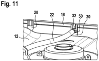
Fig. 9 und - Figur 11
- eine perspektivische Teilansicht der stirnseitigen Verschraubung der Quertraverse gem.
Fig. 9
- figure 1
- a perspective view of a pallet container according to the invention,
- figure 2
- according to an enlarged partial view of the upper area of the pallet container according to the invention
figure 1 , - figure 3
- a top view of a crossbar designed as a spring element,
- figure 4
- a side view of another embodiment of a cross member,
- figure 5
- in an enlarged partial view the right end area of a crossbeam with the screw nut inserted,
- figure 6
- according to an enlarged partial view of the left end area of the crossbeam
figure 4 , - figure 7
- an enlarged partial view with connection of a crossbeam to the upper area of a tubular lattice frame,
- figure 8
- an enlarged partial cross-sectional view with a front screw connection of a crossbeam to the upper area of the tubular lattice frame,
- figure 9
- another enlarged partial side view of a front screw connection of a crossbeam,
- figure 10
- according to an enlarged cross-sectional partial view with frontal screwing of the crossbeam.
9 and - figure 11
- a perspective partial view of the frontal screwing of the crossbeam acc.
9
In
Die Quertraversen 22, 42 sind zwischen ihren beiden Befestigungspunkten 26, 28 nicht geradlinig bzw. linear sondern bogenförmig ausgebildet und weisen einen vergleichsweise großen Bogen 34 auf. Dabei ist die Länge der Quertraversen 22 zwischen ihren beiden Befestigungspunkten 26, 28 in völlig unüblicher Weise größer ausgebildet als der direkte Abstand der beiden Befestigungspunkte 26, 28 an den Enden der Quertraversen 22.The
Um eine optimale Elastizität und Federwirkung der Quertraversen 22, 42 zu erhalten, ist vorgesehen, dass die Länge der Quertraversen entsprechend ihrer Bogenlinie zwischen ihren beiden Befestigungspunkten zwischen 1% und 5 % größer ausgebildet ist als der direkte Abstand (entsprechend einer Kreissehne) zwischen den beiden Befestigungspunkten. Dadurch wird die Größe des Bogens und die bogenförmig geschwungene Form der Quertraversen als elastisches Federelement realisiert.In order to obtain an optimal elasticity and spring effect of the
Für Standard-Palettencontainer mit einem Füllvolumen von 600, 1000 oder 1200 Litern, die eine gleiche Breiten- und Längenabmessung aufweisen, beträgt der Abstand der beiden Befestigungspunkte 26, 28 voneinander ca. 960 mm und die effektive Länge der Quertraversen 22 ungefähr 993 mm. Für die gleichen Standard-Palettencontainer sollen die bogenförmig ausgebildeten Quertraversen 22 einen großen Bogenradius zwischen 300 mm und 700 mm, vorzugsweise 500 mm, aufweisen.For standard pallet containers with a capacity of 600, 1000 or 1200 liters, which have the same width and length dimensions, the distance between the two attachment points 26, 28 from each other is approximately 960 mm and the effective length of the
Die oben beschriebene konstruktive Ausgestaltung der Erfindung ist in
Die beiden Enden der Quertraversen 22 sind mittels der Gewindeschrauben 48 in den Befestigungspunkten 26, 28 jeweils stirnseitig am oberen Ende von jeweils zwei benachbarten vertikalen Rohrstäben 20 im flachgedrückten Bereich dicht unterhalb des obersten horizontal umlaufenden Rohrstabs angeschraubt. Dabei sind die Befestigungspunkte 26, 28 der geschwungenen bogenförmigen Quertraversen 22 - im Vergleich zu bisher üblichen geraden Quertraversen - weiter zur Mitte des oberen Bereichs des Rohr-Gitterrahmens hin verschoben, dort wo die größten Ausbeulungen mit den größten Zugbelastungen auftreten und abgefangen werden sollen. Auf diese vorteilhafte Weise liegen die Befestigungspunkte 26, 28 der beiden Quertraversen 22 am oberen Ende von zwei direkt benachbarten vertikalen Rohrstäben 20. Mit den üblichen linear ausgebildeten Quertraversen wäre eine solche mittige Anbindung nicht möglich.The two ends of the
Gemäß einer anderen Bauart können die Quertraversen 22, 42 aber auch ein quadratisches Rohrprofil mit einer Seitenlänge zwischen 14 mm und 20 mm, vorzugsweise 16 mm, und eine Wandstärke zwischen 0,7 mm und 1,2 mm, vorzugsweise 0,8 mm, aufweisen.According to another type of construction, the
In
Die vergrößerte Darstellung in
Eine Befestigungsmöglichkeit, bei der jeweils eine Gewindeschraube 48 stirnseitig in das Ende des Hohlrohr-Profils der Quertraverse 22 eingeschraubt wird, ist in
Dabei ist die Quertraverse 22 dicht unterhalb des obersten horizontalen Rohrstabs 18 mittels der stirnseitig von außen - in Horizontalrichtung - eingedrehten Gewindeschrauben 48 an den oberen flachgedrückten Enden von zwei sich gegenüberliegenden vertikalen Rohrstäben 20 fixiert.The
Eine andere Befestigungsmöglichkeit mit stirnseitiger Verschraubung der Quertraverse 42 mit 2 kleinen Bögen 36 ist in vergrößerter Darstellung in
Die horizontalen oder vertikalen Rohrstäbe 18, 20 des Rohr-Gitterrahmens 14 sind zum Einschrauben der Gewindeschrauben 48 in die Enden der Quertraversen 22, 42 mit einer entsprechenden Bohrung für die Gewindeschrauben 48 versehen.The horizontal or vertical
Die stirnseitigen Verschraubungen der Quertraversen haben den großen Vorteil, dass die Schraubenspitzen der Gewindeschrauben vollkommen im Hohlrohr-Profil der Quertraversen 22, 42 sitzen und verdeckt sind, so dass es bei der Handhabung von erfindungsgemäßen Palettencontainern zu keinen Verletzungen mehr kommen kann, wie es bei bisher üblichen offenen Verschraubungen mit hervorstehender Schraubenspitze häufig der Fall war.The front screw connections of the crossbeams have the great advantage that the screw tips of the threaded screws sit completely in the hollow tube profile of the
Bisher übliche gerade Quertraversen können nur schlecht mit Schrauben stirnseitig direkt in der Mittelachse verschraubt werden. Beim Anziehen der Schrauben dreht die Quertraverse mit und sie müsste für die Montage fixiert werden. Diese Fixierung entfällt in vorteilhafter Weise bei der bogenförmig geschwungenen Form der erfindungsgemäßen Quertraversen.Straight crossbeams that have been customary up to now can only be screwed directly into the central axis with screws on the face side with difficulty. When tightening the screws, the crossbar rotates and it would have to be fixed for assembly. This fixation is eliminated in an advantageous manner with the arched shape of the crossbeams according to the invention.
Bei der bevorzugten erfindungsgemäßen Ausgestaltung der Quertraversen 22, 42 sind die beiden Enden der Quertraversen 22, 42 stark in Radialrichtung eingequetscht, wobei direkt in die Einquetschungen 32 ein entsprechendes Innengewinde, z. B. M8 eingeformt ist.In the preferred embodiment of the invention, the
In
Schließlich zeigt
Bei allen aufgezeigten Varianten sind die beiden Enden der Quertraversen 22, 42 stirnseitig an dem obersten horizontalen Rohrstab 18 oder an vier vertikalen Rohrstäben 20 des Rohr-Gitterrahmens fest aber wieder lösbar zum Zweck eines Austausches des Kunststoff-Innenbehälters 12 angeschraubt.In all variants shown, the two ends of the
Die verschiedenen bogenförmig ausgeführten Versionen der Quertraversen 22, 42 als Federelement ermöglichen eine unterschiedliche Gestaltung der Befestigung mit horizontaler oder vertikaler Verschraubung der beiden Enden der Quertraversen 22, 42 am oberen Rohr-Gitterrahmen 14.The various curved versions of the
Die beschriebenen Ausführungen der Quertraversen und der Befestigungsmöglichkeiten können im Rahmen der vorliegenden Erfindung einfach miteinander kombiniert und gegeneinander ausgetauscht werden.Within the scope of the present invention, the described embodiments of the crossbeams and the fastening options can easily be combined with one another and interchanged with one another.
Fazit : Durch die erfindungsgemäße stirnseitige Verschraubung der Quertraversen 22, 42 mit vollkommen abgedeckten Gewindeschrauben - die quasi in den Enden der Quertraversen verschwinden - kann bei einem Palettencontainer 10 auf vergleichsweise einfache Art und Weise der obere Bereich des Rohr-Gitterrahmens 14 in Hinblick auf eine Verletzungsgefahr sicherer gestaltet und die Betriebssicherheit bei der Handhabung von befüllten Palettencontainern maßgeblich erhöht werden. Conclusion: Due to the inventive screw connection of the
- 1010
- Palettencontainerpallet container
- 1212
- Kunststoff-InnenbehälterPlastic inner container
- 1414
- Rohr-Gitterrahmentubular lattice frame
- 1616
- Bodenpalettefloor pallet
- 1818
- horizontale Rohrstäbe (14)horizontal tube bars (14)
- 2020
- vertikale Rohrstäbe (14)Vertical Tube Bars (14)
- 2222
- Quertraversecrossbeam
- 2424
- Federelement (22)spring element (22)
- 2626
- Befestigungspunkt (22)attachment point (22)
- 2828
- gegenüberliegender Befestigungspunkt (22)opposite attachment point (22)
- 3030
- Schraubmutter (22)nut (22)
- 3232
- Einquetschung (22)crushing (22)
- 3434
- großer Bogen (22)big bow (22)
- 3636
- kleiner Bogen (22)small bow (22)
- 3838
- Oberboden (12)top floor (12)
- 4040
- Halteöse (38)retaining eyelet (38)
- 4242
- Quertraverse 2-BögenCrossbeam 2 arches
- 4444
- Innengewinde (30)internal thread (30)
- 4646
- Innengewinde (32)internal thread (32)
- 4848
- Gewindeschraube (30, 32)threaded screw (30, 32)
- 5050
- verlängerter flachgedrückter Bereich (20)Extended Flattened Area (20)
Claims (12)
- A pallet container (10) for storing and transporting fluid or flowable filling materials, having a thin-walled, rigid plastics inner container (12) made from thermoplastic plastics material, having a tubular grid frame (14) which tightly surrounds the plastics inner container (12) as a supporting covering and which comprises horizontal and vertical tubular rods (18, 20) which are welded to each other, and having a base pallet (16) on which the plastics inner container (12) is positioned and to which the tubular grid frame (14) is securely connected, wherein two rod-shaped transverse cross-members (22) are provided above the plastics inner container (12) and are fixed with the two ends thereof via a screw connection by means of threaded screws (48) to two mutually opposite side walls in the upper region of the tubular grid frame (14),
characterized in that
the transverse cross-members (22, 42) are screwed at their fastening points (26, 28) on the end face of their two ends against two mutually opposite tubular rods (18, 20) in the upper region of the tubular grid frame (14) and the threaded screws (48) axially lead into the ends (52) of the transverse cross-members (22, 42). - The pallet container (10) as claimed in claim 1,
characterized in that
a screw nut (30) with an internal thread (44) is inserted in a non-releasably secure manner in both ends of the transverse cross-members (22, 42) having a hollow tubular profile and the transverse cross-members (22, 42) are screwed firmly but releasably to an upper horizontal or vertical tubular rod (18, 20) of the tubular grid frame (14) by means of the threaded screws (48) which are screwed in on the end face. - The pallet container (10) as claimed in claim 1,
characterized in that
the two ends of the transverse cross-members (22, 42) are strongly compressed and an internal thread (46) is directly formed in these compressed portions (32), wherein the transverse cross-members (22, 42) are screwed firmly but releasably to an upper horizontal or vertical tubular rod (18, 20) of the tubular grid frame (14) by means of the threaded screws (48) screwed in at the end face. - The pallet container (10) as claimed in claim 1, 2 or 3,
characterized in that
the two ends of the transverse cross-members (22, 42) are each screwed at two mutually opposite vertical tubular rods (20) closely underneath the uppermost horizontally extending tubular rod (18). - The pallet container (10) as claimed in claim 1, 2, 3 or 4,
characterized in that
the two ends of the transverse cross-members (22, 42) are screwed in the completely flattened region of the vertical tubular rods (20). - The pallet container (10) as claimed in claim 1, 2, 3, 4 or 5,
characterized in that
the flattened regions (50) of the vertical tubular rods (20) with the screwed-in transverse cross-members (22, 42) are designed to be flattened longer than the flattened regions of the remaining vertical tubular rods (20). - The pallet container (10) as claimed in claim 1, 2, 3, 4, 5 or 6,
characterized in that
the free length of the completely flattened region (50) of the vertical tubular rods (20) is between 18 mm and 45 mm, preferably 32 mm, below the uppermost horizontally extending tubular rod (18). - The pallet container (10) as claimed in claim 1, 2, 3, 4, 5, 6 or 7,
characterized in that
the two transverse cross-members (22, 42), which are screwed on their end faces are constructed not to be linear between the two fastening points (26, 28) thereof, but instead curved in the form of resilient spring elements (24) and to this end have one or more curved portions. - The pallet container (10) as claimed in one of claims 1 to 8,
characterized in that
the two transverse cross-members (22, 42) which are screwed on their end faces have a length between their two fastening points (26, 28) of between 1 % and 5%, preferably 3%, greater than the direct spacing between the two fastening points (26, 28). - The pallet container (10) as claimed in one of claims 1 to 9,
characterized in that
the transverse cross-members (22) which are screwed-in in the completely flattened region of the vertical tubular rods (20) each have a comparatively large curve (34) which is bent in the horizontal plane, wherein the arcuately curved transverse cross-members (22) are positioned flat on the upper base (38) of the plastics inner container (12) and the large curves (34) of the two transverse cross-members (22) are orientated so as to be directed away from each other. - The pallet container (10) as claimed in one of claims 1 to 10,
characterized in that
the transverse cross-members are constructed not to be linear between the two fastening points (26, 28) thereof, but are each provided at their two ends with a small, downwardly formed curve (36) and are each screwed with their end faces from below against the uppermost circumferential horizontal tubular rod (18). - The pallet container (10) as claimed in one of claims 1 to 10,
characterized in that
the transverse cross-members (22, 42) have a round or oval tubular profile with a diameter between 14 mm and 22 mm, preferably 16 mm, and a wall thickness between 0.7 mm and 1.2 mm, preferably 0.8 mm.
Applications Claiming Priority (3)
| Application Number | Priority Date | Filing Date | Title |
|---|---|---|---|
| DE202019004316 | 2019-10-18 | ||
| DE202019004962 | 2019-12-05 | ||
| PCT/EP2020/000178 WO2021073766A1 (en) | 2019-10-18 | 2020-10-16 | Pallet container |
Publications (2)
| Publication Number | Publication Date |
|---|---|
| EP4045429A1 EP4045429A1 (en) | 2022-08-24 |
| EP4045429B1 true EP4045429B1 (en) | 2023-06-07 |
Family
ID=73172642
Family Applications (2)
| Application Number | Title | Priority Date | Filing Date |
|---|---|---|---|
| EP20803439.7A Active EP4045429B1 (en) | 2019-10-18 | 2020-10-16 | Pallet container |
| EP20803440.5A Active EP4045430B8 (en) | 2019-10-18 | 2020-10-16 | Pallet container |
Family Applications After (1)
| Application Number | Title | Priority Date | Filing Date |
|---|---|---|---|
| EP20803440.5A Active EP4045430B8 (en) | 2019-10-18 | 2020-10-16 | Pallet container |
Country Status (13)
| Country | Link |
|---|---|
| US (2) | US20240140674A1 (en) |
| EP (2) | EP4045429B1 (en) |
| JP (2) | JP2022552842A (en) |
| KR (2) | KR20220084360A (en) |
| CN (2) | CN114514184A (en) |
| AU (2) | AU2020365203A1 (en) |
| BR (2) | BR112022006277A2 (en) |
| CA (2) | CA3153773A1 (en) |
| ES (2) | ES2955336T3 (en) |
| IL (2) | IL292154A (en) |
| MX (2) | MX2022004447A (en) |
| PL (2) | PL4045430T3 (en) |
| WO (2) | WO2021073766A1 (en) |
Family Cites Families (13)
| Publication number | Priority date | Publication date | Assignee | Title |
|---|---|---|---|---|
| DE9202045U1 (en) * | 1992-02-18 | 1992-09-17 | Mauser-Werke Gmbh, 5040 Bruehl, De | |
| DE4425630C2 (en) | 1994-04-15 | 1996-09-05 | Protechna Sa | Transport and storage containers for liquids |
| KR20030015251A (en) * | 2000-05-25 | 2003-02-20 | 마우저-베르케 게엠베하 운트 코. 카게 | Palette container |
| DE10301517B3 (en) * | 2003-01-17 | 2004-03-11 | Protechna S.A. | Transport and storage container for liquid has vertical grid rods of grid mantle enclosing inner plastics container welded to upper edge profile supporting stacked container |
| AU2004233969B2 (en) * | 2003-04-25 | 2010-03-04 | Mauser-Werke Gmbh | Pallet container |
| WO2012085940A2 (en) | 2010-12-24 | 2012-06-28 | Genex Science And Technologies Pvt. Ltd. | Pallet container with riveted cage |
| DE202013000624U1 (en) * | 2012-09-21 | 2013-03-07 | Mauser-Werke Gmbh | pallet container |
| DE102013213167A1 (en) * | 2013-07-04 | 2015-01-22 | Protechna S.A. | Inner container made of plastic as well as transport and storage containers for liquids with such an inner container |
| FR3037931A1 (en) * | 2015-06-26 | 2016-12-30 | Sotralentz Packaging | STACKABLE PALLET CONTAINER WITH SUPERIOR REINFORCEMENT FRAME |
| EP3335018B1 (en) * | 2015-08-12 | 2020-09-16 | Shuttle Gauge IP Pty Ltd | Volume measurement apparatus |
| DE102015016814A1 (en) * | 2015-12-23 | 2017-06-29 | Protechna S.A. | Transport and storage container for liquids |
| DE102016000072B4 (en) * | 2016-01-07 | 2018-11-29 | Mauser-Werke Gmbh | pallet container |
| PT3509963T (en) * | 2016-09-12 | 2021-09-29 | Mauser Werke Gmbh | Pallet container |
-
2020
- 2020-10-16 CA CA3153773A patent/CA3153773A1/en active Pending
- 2020-10-16 IL IL292154A patent/IL292154A/en unknown
- 2020-10-16 WO PCT/EP2020/000178 patent/WO2021073766A1/en active Application Filing
- 2020-10-16 PL PL20803440.5T patent/PL4045430T3/en unknown
- 2020-10-16 BR BR112022006277A patent/BR112022006277A2/en unknown
- 2020-10-16 CA CA3153751A patent/CA3153751A1/en active Pending
- 2020-10-16 EP EP20803439.7A patent/EP4045429B1/en active Active
- 2020-10-16 AU AU2020365203A patent/AU2020365203A1/en active Pending
- 2020-10-16 PL PL20803439.7T patent/PL4045429T3/en unknown
- 2020-10-16 AU AU2020367194A patent/AU2020367194A1/en active Pending
- 2020-10-16 BR BR112022006301A patent/BR112022006301A2/en unknown
- 2020-10-16 MX MX2022004447A patent/MX2022004447A/en unknown
- 2020-10-16 ES ES20803439T patent/ES2955336T3/en active Active
- 2020-10-16 ES ES20803440T patent/ES2956513T3/en active Active
- 2020-10-16 CN CN202080072042.XA patent/CN114514184A/en active Pending
- 2020-10-16 WO PCT/EP2020/000179 patent/WO2021073767A1/en active Application Filing
- 2020-10-16 JP JP2022522899A patent/JP2022552842A/en active Pending
- 2020-10-16 MX MX2022004448A patent/MX2022004448A/en unknown
- 2020-10-16 US US17/768,739 patent/US20240140674A1/en active Pending
- 2020-10-16 KR KR1020227016574A patent/KR20220084360A/en unknown
- 2020-10-16 US US17/769,538 patent/US20240140675A1/en active Pending
- 2020-10-16 EP EP20803440.5A patent/EP4045430B8/en active Active
- 2020-10-16 CN CN202080072003.XA patent/CN114514183A/en active Pending
- 2020-10-16 KR KR1020227016573A patent/KR20220084143A/en unknown
- 2020-10-16 JP JP2022522898A patent/JP2022553001A/en active Pending
-
2022
- 2022-04-13 IL IL292241A patent/IL292241A/en unknown
Also Published As
| Publication number | Publication date |
|---|---|
| PL4045430T3 (en) | 2023-11-27 |
| IL292241A (en) | 2022-06-01 |
| MX2022004447A (en) | 2022-05-02 |
| CN114514184A (en) | 2022-05-17 |
| CA3153773A1 (en) | 2021-04-22 |
| CN114514183A (en) | 2022-05-17 |
| EP4045430A1 (en) | 2022-08-24 |
| PL4045429T3 (en) | 2023-11-06 |
| AU2020365203A1 (en) | 2022-06-02 |
| US20240140675A1 (en) | 2024-05-02 |
| WO2021073766A1 (en) | 2021-04-22 |
| MX2022004448A (en) | 2022-05-03 |
| US20240140674A1 (en) | 2024-05-02 |
| EP4045430B1 (en) | 2023-06-21 |
| KR20220084143A (en) | 2022-06-21 |
| IL292154A (en) | 2022-06-01 |
| BR112022006301A2 (en) | 2022-06-28 |
| EP4045430B8 (en) | 2023-09-20 |
| EP4045429A1 (en) | 2022-08-24 |
| JP2022552842A (en) | 2022-12-20 |
| KR20220084360A (en) | 2022-06-21 |
| JP2022553001A (en) | 2022-12-21 |
| BR112022006277A2 (en) | 2022-06-28 |
| ES2955336T3 (en) | 2023-11-30 |
| CA3153751A1 (en) | 2021-04-22 |
| ES2956513T3 (en) | 2023-12-22 |
| WO2021073767A1 (en) | 2021-04-22 |
| AU2020367194A1 (en) | 2022-06-02 |
Similar Documents
| Publication | Publication Date | Title |
|---|---|---|
| EP0694016B1 (en) | Pallet container | |
| EP2340217B1 (en) | Pallet container | |
| EP2426067B1 (en) | Transport and storage container for fluids | |
| EP3509963A1 (en) | Pallet container | |
| EP3575238B1 (en) | Pallet container | |
| EP1754670A2 (en) | Transport and storage container for liquids | |
| DE3903392C2 (en) | ||
| EP1289852B1 (en) | Container on pallet | |
| EP4045429B1 (en) | Pallet container | |
| WO2020099994A1 (en) | Plastic pallet with protected runners | |
| DE102019008477A1 (en) | Pallet container | |
| DE112004000700B4 (en) | Pallet container with crossed tube rods | |
| EP1328447A1 (en) | Pallet container | |
| DE10002610B4 (en) | Containers for liquids and flowable products | |
| DE102019007360A1 (en) | Pallet container | |
| EP3256400A1 (en) | Pallet-type base for transportation and storage containers for liquids | |
| EP3256401B1 (en) | Pallet-type base for transportation and storage containers for liquids | |
| EP1354825B1 (en) | Refuse receptacle with reinforced trunnion units | |
| EP2143652B1 (en) | Stackable storage and transport containers | |
| EP3790815B1 (en) | Transporting and storage container for liquids | |
| EP3608247B1 (en) | Canister | |
| DE102016010889A1 (en) | pallet container | |
| DE2454606B2 (en) | CONTAINER FOR GRAINY AND DUST-SHAPED GOODS | |
| DE19818651A1 (en) | Pallet container for storing and transporting liquids | |
| DE202015009501U1 (en) | Pressure vessel or pressure line |
Legal Events
| Date | Code | Title | Description |
|---|---|---|---|
| STAA | Information on the status of an ep patent application or granted ep patent |
Free format text: STATUS: UNKNOWN |
|
| STAA | Information on the status of an ep patent application or granted ep patent |
Free format text: STATUS: THE INTERNATIONAL PUBLICATION HAS BEEN MADE |
|
| PUAI | Public reference made under article 153(3) epc to a published international application that has entered the european phase |
Free format text: ORIGINAL CODE: 0009012 |
|
| STAA | Information on the status of an ep patent application or granted ep patent |
Free format text: STATUS: REQUEST FOR EXAMINATION WAS MADE |
|
| 17P | Request for examination filed |
Effective date: 20220518 |
|
| AK | Designated contracting states |
Kind code of ref document: A1 Designated state(s): AL AT BE BG CH CY CZ DE DK EE ES FI FR GB GR HR HU IE IS IT LI LT LU LV MC MK MT NL NO PL PT RO RS SE SI SK SM TR |
|
| GRAP | Despatch of communication of intention to grant a patent |
Free format text: ORIGINAL CODE: EPIDOSNIGR1 |
|
| STAA | Information on the status of an ep patent application or granted ep patent |
Free format text: STATUS: GRANT OF PATENT IS INTENDED |
|
| DAV | Request for validation of the european patent (deleted) | ||
| DAX | Request for extension of the european patent (deleted) | ||
| INTG | Intention to grant announced |
Effective date: 20230105 |
|
| GRAS | Grant fee paid |
Free format text: ORIGINAL CODE: EPIDOSNIGR3 |
|
| GRAA | (expected) grant |
Free format text: ORIGINAL CODE: 0009210 |
|
| STAA | Information on the status of an ep patent application or granted ep patent |
Free format text: STATUS: THE PATENT HAS BEEN GRANTED |
|
| AK | Designated contracting states |
Kind code of ref document: B1 Designated state(s): AL AT BE BG CH CY CZ DE DK EE ES FI FR GB GR HR HU IE IS IT LI LT LU LV MC MK MT NL NO PL PT RO RS SE SI SK SM TR |
|
| REG | Reference to a national code |
Ref country code: GB Ref legal event code: FG4D Free format text: NOT ENGLISH |
|
| REG | Reference to a national code |
Ref country code: CH Ref legal event code: EP Ref country code: AT Ref legal event code: REF Ref document number: 1574382 Country of ref document: AT Kind code of ref document: T Effective date: 20230615 |
|
| REG | Reference to a national code |
Ref country code: DE Ref legal event code: R096 Ref document number: 502020003739 Country of ref document: DE |
|
| P01 | Opt-out of the competence of the unified patent court (upc) registered |
Effective date: 20230602 |
|
| REG | Reference to a national code |
Ref country code: NO Ref legal event code: T2 Effective date: 20230607 |
|
| REG | Reference to a national code |
Ref country code: NL Ref legal event code: FP |
|
| REG | Reference to a national code |
Ref country code: LT Ref legal event code: MG9D |
|
| REG | Reference to a national code |
Ref country code: SE Ref legal event code: TRGR |
|
| PG25 | Lapsed in a contracting state [announced via postgrant information from national office to epo] |
Ref country code: RS Free format text: LAPSE BECAUSE OF FAILURE TO SUBMIT A TRANSLATION OF THE DESCRIPTION OR TO PAY THE FEE WITHIN THE PRESCRIBED TIME-LIMIT Effective date: 20230607 Ref country code: LV Free format text: LAPSE BECAUSE OF FAILURE TO SUBMIT A TRANSLATION OF THE DESCRIPTION OR TO PAY THE FEE WITHIN THE PRESCRIBED TIME-LIMIT Effective date: 20230607 Ref country code: LT Free format text: LAPSE BECAUSE OF FAILURE TO SUBMIT A TRANSLATION OF THE DESCRIPTION OR TO PAY THE FEE WITHIN THE PRESCRIBED TIME-LIMIT Effective date: 20230607 Ref country code: HR Free format text: LAPSE BECAUSE OF FAILURE TO SUBMIT A TRANSLATION OF THE DESCRIPTION OR TO PAY THE FEE WITHIN THE PRESCRIBED TIME-LIMIT Effective date: 20230607 Ref country code: GR Free format text: LAPSE BECAUSE OF FAILURE TO SUBMIT A TRANSLATION OF THE DESCRIPTION OR TO PAY THE FEE WITHIN THE PRESCRIBED TIME-LIMIT Effective date: 20230908 |
|
| REG | Reference to a national code |
Ref country code: ES Ref legal event code: FG2A Ref document number: 2955336 Country of ref document: ES Kind code of ref document: T3 Effective date: 20231130 |
|
| PG25 | Lapsed in a contracting state [announced via postgrant information from national office to epo] |
Ref country code: FI Free format text: LAPSE BECAUSE OF FAILURE TO SUBMIT A TRANSLATION OF THE DESCRIPTION OR TO PAY THE FEE WITHIN THE PRESCRIBED TIME-LIMIT Effective date: 20230607 |
|
| PG25 | Lapsed in a contracting state [announced via postgrant information from national office to epo] |
Ref country code: SK Free format text: LAPSE BECAUSE OF FAILURE TO SUBMIT A TRANSLATION OF THE DESCRIPTION OR TO PAY THE FEE WITHIN THE PRESCRIBED TIME-LIMIT Effective date: 20230607 |
|
| PG25 | Lapsed in a contracting state [announced via postgrant information from national office to epo] |
Ref country code: IS Free format text: LAPSE BECAUSE OF FAILURE TO SUBMIT A TRANSLATION OF THE DESCRIPTION OR TO PAY THE FEE WITHIN THE PRESCRIBED TIME-LIMIT Effective date: 20231007 |
|
| PG25 | Lapsed in a contracting state [announced via postgrant information from national office to epo] |
Ref country code: SM Free format text: LAPSE BECAUSE OF FAILURE TO SUBMIT A TRANSLATION OF THE DESCRIPTION OR TO PAY THE FEE WITHIN THE PRESCRIBED TIME-LIMIT Effective date: 20230607 Ref country code: SK Free format text: LAPSE BECAUSE OF FAILURE TO SUBMIT A TRANSLATION OF THE DESCRIPTION OR TO PAY THE FEE WITHIN THE PRESCRIBED TIME-LIMIT Effective date: 20230607 Ref country code: RO Free format text: LAPSE BECAUSE OF FAILURE TO SUBMIT A TRANSLATION OF THE DESCRIPTION OR TO PAY THE FEE WITHIN THE PRESCRIBED TIME-LIMIT Effective date: 20230607 Ref country code: PT Free format text: LAPSE BECAUSE OF FAILURE TO SUBMIT A TRANSLATION OF THE DESCRIPTION OR TO PAY THE FEE WITHIN THE PRESCRIBED TIME-LIMIT Effective date: 20231009 Ref country code: IS Free format text: LAPSE BECAUSE OF FAILURE TO SUBMIT A TRANSLATION OF THE DESCRIPTION OR TO PAY THE FEE WITHIN THE PRESCRIBED TIME-LIMIT Effective date: 20231007 Ref country code: EE Free format text: LAPSE BECAUSE OF FAILURE TO SUBMIT A TRANSLATION OF THE DESCRIPTION OR TO PAY THE FEE WITHIN THE PRESCRIBED TIME-LIMIT Effective date: 20230607 Ref country code: CZ Free format text: LAPSE BECAUSE OF FAILURE TO SUBMIT A TRANSLATION OF THE DESCRIPTION OR TO PAY THE FEE WITHIN THE PRESCRIBED TIME-LIMIT Effective date: 20230607 |
|
| PGFP | Annual fee paid to national office [announced via postgrant information from national office to epo] |
Ref country code: IT Payment date: 20231031 Year of fee payment: 4 |
|
| PGFP | Annual fee paid to national office [announced via postgrant information from national office to epo] |
Ref country code: NL Payment date: 20240126 Year of fee payment: 4 |
|
| REG | Reference to a national code |
Ref country code: DE Ref legal event code: R097 Ref document number: 502020003739 Country of ref document: DE |
|
| PLBE | No opposition filed within time limit |
Free format text: ORIGINAL CODE: 0009261 |
|
| STAA | Information on the status of an ep patent application or granted ep patent |
Free format text: STATUS: NO OPPOSITION FILED WITHIN TIME LIMIT |
|
| PGFP | Annual fee paid to national office [announced via postgrant information from national office to epo] |
Ref country code: IE Payment date: 20240126 Year of fee payment: 4 Ref country code: ES Payment date: 20240129 Year of fee payment: 4 |
|
| PG25 | Lapsed in a contracting state [announced via postgrant information from national office to epo] |
Ref country code: DK Free format text: LAPSE BECAUSE OF FAILURE TO SUBMIT A TRANSLATION OF THE DESCRIPTION OR TO PAY THE FEE WITHIN THE PRESCRIBED TIME-LIMIT Effective date: 20230607 |
|
| PGFP | Annual fee paid to national office [announced via postgrant information from national office to epo] |
Ref country code: DE Payment date: 20240201 Year of fee payment: 4 Ref country code: CH Payment date: 20240126 Year of fee payment: 4 |
|
| PG25 | Lapsed in a contracting state [announced via postgrant information from national office to epo] |
Ref country code: SI Free format text: LAPSE BECAUSE OF FAILURE TO SUBMIT A TRANSLATION OF THE DESCRIPTION OR TO PAY THE FEE WITHIN THE PRESCRIBED TIME-LIMIT Effective date: 20230607 |