EP3973166B1 - Energieumwandlungsvorrichtung und steuerungssystem - Google Patents
Energieumwandlungsvorrichtung und steuerungssystem Download PDFInfo
- Publication number
- EP3973166B1 EP3973166B1 EP20732354.4A EP20732354A EP3973166B1 EP 3973166 B1 EP3973166 B1 EP 3973166B1 EP 20732354 A EP20732354 A EP 20732354A EP 3973166 B1 EP3973166 B1 EP 3973166B1
- Authority
- EP
- European Patent Office
- Prior art keywords
- engine
- piston
- chiller
- working fluid
- monolithic
- Prior art date
- Legal status (The legal status is an assumption and is not a legal conclusion. Google has not performed a legal analysis and makes no representation as to the accuracy of the status listed.)
- Active
Links
Images


Classifications
-
- B—PERFORMING OPERATIONS; TRANSPORTING
- B33—ADDITIVE MANUFACTURING TECHNOLOGY
- B33Y—ADDITIVE MANUFACTURING, i.e. MANUFACTURING OF THREE-DIMENSIONAL [3-D] OBJECTS BY ADDITIVE DEPOSITION, ADDITIVE AGGLOMERATION OR ADDITIVE LAYERING, e.g. BY 3-D PRINTING, STEREOLITHOGRAPHY OR SELECTIVE LASER SINTERING
- B33Y80/00—Products made by additive manufacturing
-
- F—MECHANICAL ENGINEERING; LIGHTING; HEATING; WEAPONS; BLASTING
- F02—COMBUSTION ENGINES; HOT-GAS OR COMBUSTION-PRODUCT ENGINE PLANTS
- F02G—HOT GAS OR COMBUSTION-PRODUCT POSITIVE-DISPLACEMENT ENGINE PLANTS; USE OF WASTE HEAT OF COMBUSTION ENGINES; NOT OTHERWISE PROVIDED FOR
- F02G1/00—Hot gas positive-displacement engine plants
- F02G1/04—Hot gas positive-displacement engine plants of closed-cycle type
- F02G1/043—Hot gas positive-displacement engine plants of closed-cycle type the engine being operated by expansion and contraction of a mass of working gas which is heated and cooled in one of a plurality of constantly communicating expansible chambers, e.g. Stirling cycle type engines
- F02G1/044—Hot gas positive-displacement engine plants of closed-cycle type the engine being operated by expansion and contraction of a mass of working gas which is heated and cooled in one of a plurality of constantly communicating expansible chambers, e.g. Stirling cycle type engines having at least two working members, e.g. pistons, delivering power output
-
- F—MECHANICAL ENGINEERING; LIGHTING; HEATING; WEAPONS; BLASTING
- F02—COMBUSTION ENGINES; HOT-GAS OR COMBUSTION-PRODUCT ENGINE PLANTS
- F02G—HOT GAS OR COMBUSTION-PRODUCT POSITIVE-DISPLACEMENT ENGINE PLANTS; USE OF WASTE HEAT OF COMBUSTION ENGINES; NOT OTHERWISE PROVIDED FOR
- F02G1/00—Hot gas positive-displacement engine plants
- F02G1/04—Hot gas positive-displacement engine plants of closed-cycle type
- F02G1/043—Hot gas positive-displacement engine plants of closed-cycle type the engine being operated by expansion and contraction of a mass of working gas which is heated and cooled in one of a plurality of constantly communicating expansible chambers, e.g. Stirling cycle type engines
- F02G1/045—Controlling
- F02G1/047—Controlling by varying the heating or cooling
-
- F—MECHANICAL ENGINEERING; LIGHTING; HEATING; WEAPONS; BLASTING
- F02—COMBUSTION ENGINES; HOT-GAS OR COMBUSTION-PRODUCT ENGINE PLANTS
- F02G—HOT GAS OR COMBUSTION-PRODUCT POSITIVE-DISPLACEMENT ENGINE PLANTS; USE OF WASTE HEAT OF COMBUSTION ENGINES; NOT OTHERWISE PROVIDED FOR
- F02G1/00—Hot gas positive-displacement engine plants
- F02G1/04—Hot gas positive-displacement engine plants of closed-cycle type
- F02G1/043—Hot gas positive-displacement engine plants of closed-cycle type the engine being operated by expansion and contraction of a mass of working gas which is heated and cooled in one of a plurality of constantly communicating expansible chambers, e.g. Stirling cycle type engines
- F02G1/045—Controlling
- F02G1/05—Controlling by varying the rate of flow or quantity of the working gas
-
- F—MECHANICAL ENGINEERING; LIGHTING; HEATING; WEAPONS; BLASTING
- F02—COMBUSTION ENGINES; HOT-GAS OR COMBUSTION-PRODUCT ENGINE PLANTS
- F02G—HOT GAS OR COMBUSTION-PRODUCT POSITIVE-DISPLACEMENT ENGINE PLANTS; USE OF WASTE HEAT OF COMBUSTION ENGINES; NOT OTHERWISE PROVIDED FOR
- F02G1/00—Hot gas positive-displacement engine plants
- F02G1/04—Hot gas positive-displacement engine plants of closed-cycle type
- F02G1/043—Hot gas positive-displacement engine plants of closed-cycle type the engine being operated by expansion and contraction of a mass of working gas which is heated and cooled in one of a plurality of constantly communicating expansible chambers, e.g. Stirling cycle type engines
- F02G1/053—Component parts or details
- F02G1/055—Heaters or coolers
-
- F—MECHANICAL ENGINEERING; LIGHTING; HEATING; WEAPONS; BLASTING
- F02—COMBUSTION ENGINES; HOT-GAS OR COMBUSTION-PRODUCT ENGINE PLANTS
- F02G—HOT GAS OR COMBUSTION-PRODUCT POSITIVE-DISPLACEMENT ENGINE PLANTS; USE OF WASTE HEAT OF COMBUSTION ENGINES; NOT OTHERWISE PROVIDED FOR
- F02G1/00—Hot gas positive-displacement engine plants
- F02G1/04—Hot gas positive-displacement engine plants of closed-cycle type
- F02G1/043—Hot gas positive-displacement engine plants of closed-cycle type the engine being operated by expansion and contraction of a mass of working gas which is heated and cooled in one of a plurality of constantly communicating expansible chambers, e.g. Stirling cycle type engines
- F02G1/053—Component parts or details
- F02G1/057—Regenerators
-
- F—MECHANICAL ENGINEERING; LIGHTING; HEATING; WEAPONS; BLASTING
- F02—COMBUSTION ENGINES; HOT-GAS OR COMBUSTION-PRODUCT ENGINE PLANTS
- F02G—HOT GAS OR COMBUSTION-PRODUCT POSITIVE-DISPLACEMENT ENGINE PLANTS; USE OF WASTE HEAT OF COMBUSTION ENGINES; NOT OTHERWISE PROVIDED FOR
- F02G3/00—Combustion-product positive-displacement engine plants
-
- F—MECHANICAL ENGINEERING; LIGHTING; HEATING; WEAPONS; BLASTING
- F23—COMBUSTION APPARATUS; COMBUSTION PROCESSES
- F23K—FEEDING FUEL TO COMBUSTION APPARATUS
- F23K5/00—Feeding or distributing other fuel to combustion apparatus
- F23K5/02—Liquid fuel
- F23K5/14—Details thereof
- F23K5/20—Preheating devices
-
- F—MECHANICAL ENGINEERING; LIGHTING; HEATING; WEAPONS; BLASTING
- F23—COMBUSTION APPARATUS; COMBUSTION PROCESSES
- F23L—SUPPLYING AIR OR NON-COMBUSTIBLE LIQUIDS OR GASES TO COMBUSTION APPARATUS IN GENERAL ; VALVES OR DAMPERS SPECIALLY ADAPTED FOR CONTROLLING AIR SUPPLY OR DRAUGHT IN COMBUSTION APPARATUS; INDUCING DRAUGHT IN COMBUSTION APPARATUS; TOPS FOR CHIMNEYS OR VENTILATING SHAFTS; TERMINALS FOR FLUES
- F23L15/00—Heating of air supplied for combustion
- F23L15/02—Arrangements of regenerators
-
- F—MECHANICAL ENGINEERING; LIGHTING; HEATING; WEAPONS; BLASTING
- F23—COMBUSTION APPARATUS; COMBUSTION PROCESSES
- F23L—SUPPLYING AIR OR NON-COMBUSTIBLE LIQUIDS OR GASES TO COMBUSTION APPARATUS IN GENERAL ; VALVES OR DAMPERS SPECIALLY ADAPTED FOR CONTROLLING AIR SUPPLY OR DRAUGHT IN COMBUSTION APPARATUS; INDUCING DRAUGHT IN COMBUSTION APPARATUS; TOPS FOR CHIMNEYS OR VENTILATING SHAFTS; TERMINALS FOR FLUES
- F23L15/00—Heating of air supplied for combustion
- F23L15/04—Arrangements of recuperators
-
- F—MECHANICAL ENGINEERING; LIGHTING; HEATING; WEAPONS; BLASTING
- F23—COMBUSTION APPARATUS; COMBUSTION PROCESSES
- F23R—GENERATING COMBUSTION PRODUCTS OF HIGH PRESSURE OR HIGH VELOCITY, e.g. GAS-TURBINE COMBUSTION CHAMBERS
- F23R3/00—Continuous combustion chambers using liquid or gaseous fuel
- F23R3/005—Combined with pressure or heat exchangers
-
- F—MECHANICAL ENGINEERING; LIGHTING; HEATING; WEAPONS; BLASTING
- F28—HEAT EXCHANGE IN GENERAL
- F28D—HEAT-EXCHANGE APPARATUS, NOT PROVIDED FOR IN ANOTHER SUBCLASS, IN WHICH THE HEAT-EXCHANGE MEDIA DO NOT COME INTO DIRECT CONTACT
- F28D9/00—Heat-exchange apparatus having stationary plate-like or laminated conduit assemblies for both heat-exchange media, the media being in contact with different sides of a conduit wall
- F28D9/04—Heat-exchange apparatus having stationary plate-like or laminated conduit assemblies for both heat-exchange media, the media being in contact with different sides of a conduit wall the conduits being formed by spirally-wound plates or laminae
-
- F—MECHANICAL ENGINEERING; LIGHTING; HEATING; WEAPONS; BLASTING
- F28—HEAT EXCHANGE IN GENERAL
- F28F—DETAILS OF HEAT-EXCHANGE AND HEAT-TRANSFER APPARATUS, OF GENERAL APPLICATION
- F28F13/00—Arrangements for modifying heat-transfer, e.g. increasing, decreasing
- F28F13/003—Arrangements for modifying heat-transfer, e.g. increasing, decreasing by using permeable mass, perforated or porous materials
-
- F—MECHANICAL ENGINEERING; LIGHTING; HEATING; WEAPONS; BLASTING
- F28—HEAT EXCHANGE IN GENERAL
- F28F—DETAILS OF HEAT-EXCHANGE AND HEAT-TRANSFER APPARATUS, OF GENERAL APPLICATION
- F28F13/00—Arrangements for modifying heat-transfer, e.g. increasing, decreasing
- F28F13/14—Arrangements for modifying heat-transfer, e.g. increasing, decreasing by endowing the walls of conduits with zones of different degrees of conduction of heat
-
- F—MECHANICAL ENGINEERING; LIGHTING; HEATING; WEAPONS; BLASTING
- F28—HEAT EXCHANGE IN GENERAL
- F28F—DETAILS OF HEAT-EXCHANGE AND HEAT-TRANSFER APPARATUS, OF GENERAL APPLICATION
- F28F7/00—Elements not covered by group F28F1/00, F28F3/00 or F28F5/00
- F28F7/02—Blocks traversed by passages for heat-exchange media
-
- F—MECHANICAL ENGINEERING; LIGHTING; HEATING; WEAPONS; BLASTING
- F02—COMBUSTION ENGINES; HOT-GAS OR COMBUSTION-PRODUCT ENGINE PLANTS
- F02G—HOT GAS OR COMBUSTION-PRODUCT POSITIVE-DISPLACEMENT ENGINE PLANTS; USE OF WASTE HEAT OF COMBUSTION ENGINES; NOT OTHERWISE PROVIDED FOR
- F02G1/00—Hot gas positive-displacement engine plants
- F02G1/04—Hot gas positive-displacement engine plants of closed-cycle type
- F02G1/043—Hot gas positive-displacement engine plants of closed-cycle type the engine being operated by expansion and contraction of a mass of working gas which is heated and cooled in one of a plurality of constantly communicating expansible chambers, e.g. Stirling cycle type engines
- F02G1/0435—Hot gas positive-displacement engine plants of closed-cycle type the engine being operated by expansion and contraction of a mass of working gas which is heated and cooled in one of a plurality of constantly communicating expansible chambers, e.g. Stirling cycle type engines the engine being of the free piston type
-
- F—MECHANICAL ENGINEERING; LIGHTING; HEATING; WEAPONS; BLASTING
- F02—COMBUSTION ENGINES; HOT-GAS OR COMBUSTION-PRODUCT ENGINE PLANTS
- F02G—HOT GAS OR COMBUSTION-PRODUCT POSITIVE-DISPLACEMENT ENGINE PLANTS; USE OF WASTE HEAT OF COMBUSTION ENGINES; NOT OTHERWISE PROVIDED FOR
- F02G2243/00—Stirling type engines having closed regenerative thermodynamic cycles with flow controlled by volume changes
-
- F—MECHANICAL ENGINEERING; LIGHTING; HEATING; WEAPONS; BLASTING
- F02—COMBUSTION ENGINES; HOT-GAS OR COMBUSTION-PRODUCT ENGINE PLANTS
- F02G—HOT GAS OR COMBUSTION-PRODUCT POSITIVE-DISPLACEMENT ENGINE PLANTS; USE OF WASTE HEAT OF COMBUSTION ENGINES; NOT OTHERWISE PROVIDED FOR
- F02G2244/00—Machines having two pistons
- F02G2244/02—Single-acting two piston engines
- F02G2244/06—Single-acting two piston engines of stationary cylinder type
- F02G2244/08—Single-acting two piston engines of stationary cylinder type having parallel cylinder, e.g. "Rider" engines
-
- F—MECHANICAL ENGINEERING; LIGHTING; HEATING; WEAPONS; BLASTING
- F02—COMBUSTION ENGINES; HOT-GAS OR COMBUSTION-PRODUCT ENGINE PLANTS
- F02G—HOT GAS OR COMBUSTION-PRODUCT POSITIVE-DISPLACEMENT ENGINE PLANTS; USE OF WASTE HEAT OF COMBUSTION ENGINES; NOT OTHERWISE PROVIDED FOR
- F02G2244/00—Machines having two pistons
- F02G2244/50—Double acting piston machines
- F02G2244/52—Double acting piston machines having interconnecting adjacent cylinders constituting a single system, e.g. "Rinia" engines
-
- F—MECHANICAL ENGINEERING; LIGHTING; HEATING; WEAPONS; BLASTING
- F02—COMBUSTION ENGINES; HOT-GAS OR COMBUSTION-PRODUCT ENGINE PLANTS
- F02G—HOT GAS OR COMBUSTION-PRODUCT POSITIVE-DISPLACEMENT ENGINE PLANTS; USE OF WASTE HEAT OF COMBUSTION ENGINES; NOT OTHERWISE PROVIDED FOR
- F02G2244/00—Machines having two pistons
- F02G2244/50—Double acting piston machines
- F02G2244/54—Double acting piston machines having two-cylinder twin systems, with compression in one cylinder and expansion in the other cylinder for each of the twin systems, e.g. "Finkelstein" engines
-
- F—MECHANICAL ENGINEERING; LIGHTING; HEATING; WEAPONS; BLASTING
- F02—COMBUSTION ENGINES; HOT-GAS OR COMBUSTION-PRODUCT ENGINE PLANTS
- F02G—HOT GAS OR COMBUSTION-PRODUCT POSITIVE-DISPLACEMENT ENGINE PLANTS; USE OF WASTE HEAT OF COMBUSTION ENGINES; NOT OTHERWISE PROVIDED FOR
- F02G2250/00—Special cycles or special engines
-
- F—MECHANICAL ENGINEERING; LIGHTING; HEATING; WEAPONS; BLASTING
- F02—COMBUSTION ENGINES; HOT-GAS OR COMBUSTION-PRODUCT ENGINE PLANTS
- F02G—HOT GAS OR COMBUSTION-PRODUCT POSITIVE-DISPLACEMENT ENGINE PLANTS; USE OF WASTE HEAT OF COMBUSTION ENGINES; NOT OTHERWISE PROVIDED FOR
- F02G2254/00—Heat inputs
- F02G2254/10—Heat inputs by burners
-
- F—MECHANICAL ENGINEERING; LIGHTING; HEATING; WEAPONS; BLASTING
- F02—COMBUSTION ENGINES; HOT-GAS OR COMBUSTION-PRODUCT ENGINE PLANTS
- F02G—HOT GAS OR COMBUSTION-PRODUCT POSITIVE-DISPLACEMENT ENGINE PLANTS; USE OF WASTE HEAT OF COMBUSTION ENGINES; NOT OTHERWISE PROVIDED FOR
- F02G2254/00—Heat inputs
- F02G2254/18—Heat inputs using deflectors, e.g. spirals
-
- F—MECHANICAL ENGINEERING; LIGHTING; HEATING; WEAPONS; BLASTING
- F02—COMBUSTION ENGINES; HOT-GAS OR COMBUSTION-PRODUCT ENGINE PLANTS
- F02G—HOT GAS OR COMBUSTION-PRODUCT POSITIVE-DISPLACEMENT ENGINE PLANTS; USE OF WASTE HEAT OF COMBUSTION ENGINES; NOT OTHERWISE PROVIDED FOR
- F02G2255/00—Heater tubes
- F02G2255/10—Heater tubes dome shaped
-
- F—MECHANICAL ENGINEERING; LIGHTING; HEATING; WEAPONS; BLASTING
- F02—COMBUSTION ENGINES; HOT-GAS OR COMBUSTION-PRODUCT ENGINE PLANTS
- F02G—HOT GAS OR COMBUSTION-PRODUCT POSITIVE-DISPLACEMENT ENGINE PLANTS; USE OF WASTE HEAT OF COMBUSTION ENGINES; NOT OTHERWISE PROVIDED FOR
- F02G2255/00—Heater tubes
- F02G2255/20—Heater fins
-
- F—MECHANICAL ENGINEERING; LIGHTING; HEATING; WEAPONS; BLASTING
- F02—COMBUSTION ENGINES; HOT-GAS OR COMBUSTION-PRODUCT ENGINE PLANTS
- F02G—HOT GAS OR COMBUSTION-PRODUCT POSITIVE-DISPLACEMENT ENGINE PLANTS; USE OF WASTE HEAT OF COMBUSTION ENGINES; NOT OTHERWISE PROVIDED FOR
- F02G2256/00—Coolers
- F02G2256/02—Cooler fins
-
- F—MECHANICAL ENGINEERING; LIGHTING; HEATING; WEAPONS; BLASTING
- F02—COMBUSTION ENGINES; HOT-GAS OR COMBUSTION-PRODUCT ENGINE PLANTS
- F02G—HOT GAS OR COMBUSTION-PRODUCT POSITIVE-DISPLACEMENT ENGINE PLANTS; USE OF WASTE HEAT OF COMBUSTION ENGINES; NOT OTHERWISE PROVIDED FOR
- F02G2257/00—Regenerators
-
- F—MECHANICAL ENGINEERING; LIGHTING; HEATING; WEAPONS; BLASTING
- F02—COMBUSTION ENGINES; HOT-GAS OR COMBUSTION-PRODUCT ENGINE PLANTS
- F02G—HOT GAS OR COMBUSTION-PRODUCT POSITIVE-DISPLACEMENT ENGINE PLANTS; USE OF WASTE HEAT OF COMBUSTION ENGINES; NOT OTHERWISE PROVIDED FOR
- F02G2258/00—Materials used
- F02G2258/10—Materials used ceramic
-
- F—MECHANICAL ENGINEERING; LIGHTING; HEATING; WEAPONS; BLASTING
- F02—COMBUSTION ENGINES; HOT-GAS OR COMBUSTION-PRODUCT ENGINE PLANTS
- F02G—HOT GAS OR COMBUSTION-PRODUCT POSITIVE-DISPLACEMENT ENGINE PLANTS; USE OF WASTE HEAT OF COMBUSTION ENGINES; NOT OTHERWISE PROVIDED FOR
- F02G2270/00—Constructional features
- F02G2270/40—Piston assemblies
-
- F—MECHANICAL ENGINEERING; LIGHTING; HEATING; WEAPONS; BLASTING
- F02—COMBUSTION ENGINES; HOT-GAS OR COMBUSTION-PRODUCT ENGINE PLANTS
- F02G—HOT GAS OR COMBUSTION-PRODUCT POSITIVE-DISPLACEMENT ENGINE PLANTS; USE OF WASTE HEAT OF COMBUSTION ENGINES; NOT OTHERWISE PROVIDED FOR
- F02G2270/00—Constructional features
- F02G2270/45—Piston rods
-
- F—MECHANICAL ENGINEERING; LIGHTING; HEATING; WEAPONS; BLASTING
- F02—COMBUSTION ENGINES; HOT-GAS OR COMBUSTION-PRODUCT ENGINE PLANTS
- F02G—HOT GAS OR COMBUSTION-PRODUCT POSITIVE-DISPLACEMENT ENGINE PLANTS; USE OF WASTE HEAT OF COMBUSTION ENGINES; NOT OTHERWISE PROVIDED FOR
- F02G2270/00—Constructional features
- F02G2270/80—Engines without crankshafts
-
- F—MECHANICAL ENGINEERING; LIGHTING; HEATING; WEAPONS; BLASTING
- F02—COMBUSTION ENGINES; HOT-GAS OR COMBUSTION-PRODUCT ENGINE PLANTS
- F02G—HOT GAS OR COMBUSTION-PRODUCT POSITIVE-DISPLACEMENT ENGINE PLANTS; USE OF WASTE HEAT OF COMBUSTION ENGINES; NOT OTHERWISE PROVIDED FOR
- F02G2275/00—Controls
- F02G2275/20—Controls for preventing piston over stroke
-
- F—MECHANICAL ENGINEERING; LIGHTING; HEATING; WEAPONS; BLASTING
- F02—COMBUSTION ENGINES; HOT-GAS OR COMBUSTION-PRODUCT ENGINE PLANTS
- F02G—HOT GAS OR COMBUSTION-PRODUCT POSITIVE-DISPLACEMENT ENGINE PLANTS; USE OF WASTE HEAT OF COMBUSTION ENGINES; NOT OTHERWISE PROVIDED FOR
- F02G2275/00—Controls
- F02G2275/40—Controls for starting
-
- F—MECHANICAL ENGINEERING; LIGHTING; HEATING; WEAPONS; BLASTING
- F02—COMBUSTION ENGINES; HOT-GAS OR COMBUSTION-PRODUCT ENGINE PLANTS
- F02G—HOT GAS OR COMBUSTION-PRODUCT POSITIVE-DISPLACEMENT ENGINE PLANTS; USE OF WASTE HEAT OF COMBUSTION ENGINES; NOT OTHERWISE PROVIDED FOR
- F02G2280/00—Output delivery
- F02G2280/10—Linear generators
-
- F—MECHANICAL ENGINEERING; LIGHTING; HEATING; WEAPONS; BLASTING
- F28—HEAT EXCHANGE IN GENERAL
- F28D—HEAT-EXCHANGE APPARATUS, NOT PROVIDED FOR IN ANOTHER SUBCLASS, IN WHICH THE HEAT-EXCHANGE MEDIA DO NOT COME INTO DIRECT CONTACT
- F28D21/00—Heat-exchange apparatus not covered by any of the groups F28D1/00 - F28D20/00
- F28D2021/0019—Other heat exchangers for particular applications; Heat exchange systems not otherwise provided for
- F28D2021/0026—Other heat exchangers for particular applications; Heat exchange systems not otherwise provided for for combustion engines, e.g. for gas turbines or for Stirling engines
-
- F—MECHANICAL ENGINEERING; LIGHTING; HEATING; WEAPONS; BLASTING
- F28—HEAT EXCHANGE IN GENERAL
- F28F—DETAILS OF HEAT-EXCHANGE AND HEAT-TRANSFER APPARATUS, OF GENERAL APPLICATION
- F28F2210/00—Heat exchange conduits
- F28F2210/10—Particular layout, e.g. for uniform temperature distribution
-
- F—MECHANICAL ENGINEERING; LIGHTING; HEATING; WEAPONS; BLASTING
- F28—HEAT EXCHANGE IN GENERAL
- F28F—DETAILS OF HEAT-EXCHANGE AND HEAT-TRANSFER APPARATUS, OF GENERAL APPLICATION
- F28F2250/00—Arrangements for modifying the flow of the heat exchange media, e.g. flow guiding means; Particular flow patterns
- F28F2250/04—Communication passages between channels
-
- Y—GENERAL TAGGING OF NEW TECHNOLOGICAL DEVELOPMENTS; GENERAL TAGGING OF CROSS-SECTIONAL TECHNOLOGIES SPANNING OVER SEVERAL SECTIONS OF THE IPC; TECHNICAL SUBJECTS COVERED BY FORMER USPC CROSS-REFERENCE ART COLLECTIONS [XRACs] AND DIGESTS
- Y02—TECHNOLOGIES OR APPLICATIONS FOR MITIGATION OR ADAPTATION AGAINST CLIMATE CHANGE
- Y02E—REDUCTION OF GREENHOUSE GAS [GHG] EMISSIONS, RELATED TO ENERGY GENERATION, TRANSMISSION OR DISTRIBUTION
- Y02E20/00—Combustion technologies with mitigation potential
- Y02E20/34—Indirect CO2mitigation, i.e. by acting on non CO2directly related matters of the process, e.g. pre-heating or heat recovery
-
- Y—GENERAL TAGGING OF NEW TECHNOLOGICAL DEVELOPMENTS; GENERAL TAGGING OF CROSS-SECTIONAL TECHNOLOGIES SPANNING OVER SEVERAL SECTIONS OF THE IPC; TECHNICAL SUBJECTS COVERED BY FORMER USPC CROSS-REFERENCE ART COLLECTIONS [XRACs] AND DIGESTS
- Y02—TECHNOLOGIES OR APPLICATIONS FOR MITIGATION OR ADAPTATION AGAINST CLIMATE CHANGE
- Y02T—CLIMATE CHANGE MITIGATION TECHNOLOGIES RELATED TO TRANSPORTATION
- Y02T10/00—Road transport of goods or passengers
- Y02T10/10—Internal combustion engine [ICE] based vehicles
- Y02T10/12—Improving ICE efficiencies
Definitions
- closed cycle engines may offer some improved efficiency over other engine system arrangements.
- closed cycle engine arrangements such as Stirling engines
- closed cycle engines are challenged to provide relatively larger power output or power density, or improved efficiency, relative to other engine arrangements.
- Closed cycle engines may suffer due to inefficient combustion, inefficient heat exchangers, inefficient mass transfer, heat losses to the environment, non-ideal behavior of the working fluid(s), imperfect seals, friction, pumping losses, and/or other inefficiencies and imperfections.
- improved closed cycle engines and system arrangements may provide improved power output, improved power density, or further improved efficiency.
- an improved closed cycle engine that may be provided to improve power generation and power distribution systems.
- heat transfer devices such as for heat engines, or as may be applied to power generation systems, distribution systems, propulsion systems, vehicle systems, or industrial or residential facilities.
- a closed cycle engine driving an electrical machine is known from EP 3 301 287 A1 .
- An aspect of the disclosure is directed to a system including a closed cycle engine having a piston body defining a hot side and a cold side and having a piston assembly movable within the piston body.
- An electric machine is operatively coupled with the piston assembly.
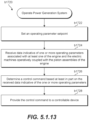
- a control system includes one or more sensors operable to detect a piston movement characteristic of the piston assembly movable within the piston body.
- a controller is communicatively coupled with the one or more sensors and a controllable device. The controller is configured to determine a control command based at least in part on data received from the one or more sensors. The control command is selected based at least in part to cause the electric machine operatively coupled with the piston assembly to generate a preselected electrical power output. The controller provides the determined control command to the controllable device.
- the controllable device is operable to control an input to an engine working fluid disposed within the piston body.
- first, second, and third may be used interchangeably to distinguish one component from another and are not intended to signify location or importance of the individual components.
- upstream and downstream refer to the relative direction with respect to fluid flow in a fluid pathway.
- upstream refers to the direction from which the fluid flows
- downstream refers to the direction to which the fluid flows.
- loop can be any suitable fluid pathway along which fluid can flow and can be either open or closed, unless stated otherwise.
- Power generation and distribution systems are generally challenged to reduce production inefficiencies, transmission losses, and emissions (e.g., oxides of nitrogen, sulfur, or carbon) during and post energy production.
- emissions e.g., oxides of nitrogen, sulfur, or carbon
- EIA U.S. Energy Information Administration
- T&D electricity transmission and distribution
- overall electrical efficiency at the end user e.g., residences, businesses, etc.
- Local, distributed, or on-demand power generation may not require access to T&D networks or grids, such as to result in an at least 5% improvement in efficiency, in addition to reducing emission and adverse environmental impacts.
- power generation may account for approximately one-third of national greenhouse gas emissions.
- Transportation may further account for another approximately one-third of national greenhouse gas emissions, about 85% of which may be from ground transportation vehicles (e.g., cars, trucks, buses, etc.).
- ground transportation vehicles e.g., cars, trucks, buses, etc.
- Known systems for reducing emissions include chemical or catalytic reduction after-treatment. However, such systems may be expensive to acquire and maintain, complex, or heavy, thereby reducing overall system efficiency. Additionally, such systems may be difficult to regulate, such that emissions reduction benefits may be lost after initial acquisition.
- known systems have resulted in reducing emissions of high reactive gases such as unburned hydrocarbons, volatile organic compounds, or oxides of sulfur or nitrogen, emissions of greenhouse gases such as carbon dioxide may generally correspond or increase with power generation and consumption.
- Power generation and distribution systems may turn to renewable energy sources such as solar, wind, or tidal energy to reduce emissions.
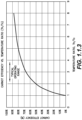
- renewable energy sources are often periodic or unpredictable, such as depicted in FIG. 1.1.1 and FIG. 1.1.2 .
- available sunlight for solar power generation is dependent on the time of day and weather.
- wind power generation is dependent on weather patterns and may be both unpredictable and irregular.
- tidal power generation is dependent on currents and lunar phases.
- renewable energy sources are difficult to incorporate to transportation systems due to size, scale, and desired power output and density.
- Such issues and barriers from power generation and distribution systems may further pose barriers to developing or expanding access to clean water, water desalination, and food security.
- smaller scale or portable power generation systems that may overcome distribution obstacles may nonetheless be challenged to provide a necessary power density and output.
- Such limitations in power density and output may generally result in an inability to apply smaller scale or portable power generation systems to rural areas or developing nations.
- smaller scale or portable power generation system may generally provide inadequate power density and output for providing water to rural or less population-dense areas.
- the system A10 further includes a chiller assembly, such as chiller assembly A40 further described herein.
- the chiller assembly A40 is configured to receive and displace thermal energy from a compression chamber A222 of the engine.
- the system A10 includes a cold side heat exchanger A42 thermally coupled to the compression chamber A222 of the closed cycle engine and the chiller assembly.
- the cold side heat exchanger A42 and the piston body C700 defining the compression chamber A222 of the engine are together defined as an integral, unitary structure, such as further shown and described in regard to FIGS. 1.4.1-1.4.7 .
- the cold side heat exchanger A42, at least a portion of the piston body C700 defining the compression chamber A222, and at least a portion of the chiller assembly together define an integral, unitary structure.
- the chiller assembly A40 is a bottoming cycle to the engine A100. As such, the chiller assembly A40 is configured to receive thermal energy from the engine A100. The thermal energy received at the chiller assembly A40, such as through a cold side heat exchanger A42, or cold side heat exchanger A170 further herein, from the engine A100 is added to a chiller working fluid at the chiller assembly A40.
- the chiller assembly A40 defines a Rankine cycle system through which the chiller working fluid flows in closed loop arrangement with a compressor. In some embodiments, the chiller working fluid is further in closed loop arrangement with an expander.
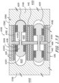
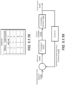
- the system A10 includes a heat exchanger A88 ( FIG. 1.3.2 ).
- the heat exchanger A188 may include a condenser or radiator.
- the cold side heat exchanger A40 is positioned downstream of the compressor and upstream of the expander and in thermal communication with a compression chamber A222 of the closed cycle engine, such as further depicted and described in regard to FIG. 1.3.1 - FIG. 1.3.2 .
- the cold side heat exchanger A42 may generally define an evaporator receiving thermal energy from the engine A40.
- the chiller assembly A40 may include a substantially constant density heat exchanger.
- the constant density heat exchanger generally includes a chamber including an inlet and an outlet each configured to contain or trap a portion of the chiller working fluid for a period of time as heat from the closed cycle engine is transferred to the cold side heat exchanger A42.
- the chamber may define a linear or rotary chamber at which the inlet and the outlet are periodically opened and closed via valves or ports such as to trap the chiller working fluid within the chamber for the desired amount of time.
- the rate at which the inlet and the outlet of the chamber defining the constant density heat exchanger is a function at least of velocity of a particle of fluid trapped within the chamber between the inlet and the outlet.
- the chiller assembly A40 including the constant density heat exchanger may provide efficiencies, or efficiency increases, performances, power densities, etc. at the system A10 such as further described herein.
- the chiller assembly A40 of the system A10 may include a thermal energy sink generally.
- the chiller assembly A40 may include a body of water, the vacuum of space, ambient air, liquid metal, inert gas, etc.
- the chiller working fluid at the chiller assembly A40 may include, but is not limited to, compressed air, water or water-based solutions, oil or oil-based solutions, or refrigerants, including, but not limited to, class 1, class 2, or class 3 refrigerants.
- refrigerants may include, but are not limited to, a supercritical fluid including, but not limited to, carbon dioxide, water, methane, ethane, propane, ethylene, propylene, methanol, ethanol, acetone, or nitrous oxide, or combinations thereof.
- a supercritical fluid including, but not limited to, carbon dioxide, water, methane, ethane, propane, ethylene, propylene, methanol, ethanol, acetone, or nitrous oxide, or combinations thereof.
- refrigerant may include, but are not limited to, methylamine, ethylamine, hydrogen, helium, ammonia, water, neon, nitrogen, air, oxygen, argon, sulfur dioxide, carbon dioxide, nitrous oxide, or krypton, or combinations thereof.
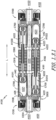
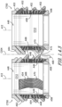
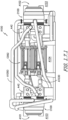
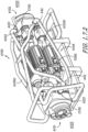
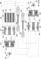
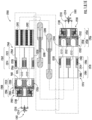
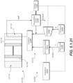
- FIG. 1.3.1 is an exemplary cross sectional view of the system A10 including the heater body C100 and the chiller assembly A40 each in thermal communication with the engine A100, or particularly the engine working fluid within the engine A100, such as shown and described according to the schematic block diagram of FIG. 1.2.1 .
- FIG. 1.3.2 is an exemplary cutaway perspective view of a portion of the engine A100.
- the system A10 includes a closed cycle engine A100 including a piston assembly A1010 positioned within a volume or piston chamber C112 ( FIGS. 1.8.1A - FIG. 1.8.1F ) defined by a wall defining a piston body C700.
- the volume within the piston body C700 is separated into a first chamber, or hot chamber, or expansion chamber A221 and a second chamber, or cold chamber (relative to the hot chamber), or compression chamber A222 by a piston A1011 of the piston assembly A1010.
- the expansion chamber A221 is positioned thermally proximal to the heater body C100 relative to the compression chamber A222 thermally distal to the heater body C100.
- the compression chamber A222 is positioned thermally proximal to the chiller assembly A40 relative to the expansion chamber A221 thermally distal to the chiller assembly A40.
- the piston assembly A1010 defines a double-ended piston assembly A1010 in which a pair of pistons A1011 is each coupled to a connection member A1030.
- the connection member A1030 may generally define a rigid shaft or rod extended along a direction of motion of the piston assembly A1010.
- the connection members A1030 includes one or more springs or spring assemblies, such as further provided herein, providing flexible or non-rigid movement of the connection member A1030.
- the connection member A1030 may further define substantially U- or V- connections between the pair of pistons A1011.
- Each piston A1011 is positioned within the piston body C700 such as to define the expansion chamber A221 and the compression chamber A222 within the volume of the piston body C700.
- the load device c092 is operably coupled to the piston assembly A1010 such as to extract energy therefrom, provide energy thereto, or both.
- the load device c092 defining an electric machine is in magnetic communication with the closed cycle engine via the connection member A1030.
- the piston assembly A1010 includes a dynamic member A181 positioned in operable communication with a stator assembly A182 of the electric machine.
- the stator assembly A182 may generally include a plurality of windings wrapped circumferentially relative to the piston assembly A1010 and extended along a lateral direction L.
- the dynamic member A181 is connected to the connection member A1030.
- the electric machine may further be positioned between the pair of pistons A1011 of each piston assembly A1010.
- Dynamic motion of the piston assembly A1010 generates electricity at the electric machine.
- linear motion of the dynamic member A181 between each pair of chambers defined by each piston A1011 of the piston assembly A1010 generates electricity via the magnetic communication with the stator assembly A182 surrounding the dynamic member A181.
- the working fluid body C108 may further define at least a portion of the expansion chamber A221.
- the working fluid body C108 defines a unitary or monolithic structure with at least a portion of the piston body C700, such as to define at least a portion of the expansion chamber A221.
- the heater body C100 further defines at least a portion of the working fluid body C108, such as to define a unitary or monolithic structure with the working fluid body C108, such as further described herein. In one embodiment, such as further shown and described in regard to FIG.
- the system A10 includes the hot side heat exchanger or working fluid body C108 positioned between the heater body C100 and the expansion chamber A221 of the piston body C700.
- the working fluid body C108 includes a plurality of heater conduits or working fluid pathways C110 extended from the expansion chamber A221.
- the engine A100 defines an outer end A103 and an inner end A104 each relative to a lateral direction L.
- the outer ends A103 define laterally distal ends of the engine A100 and the inner ends 104 define laterally inward or central positions of the engine A100.
- the heater body C100 is positioned at outer ends A103 of the system A10.
- the piston body C700 includes a dome structure A26 at the expansion chamber A221.
- the expansion chamber dome structure A26 s provides reduced surface area heat losses across the outer end A103 of the expansion chamber A221.
- the pistons A1011 of the piston assembly A1010 further include domed pistons A1011 corresponding to the expansion chamber A221 dome.
- the dome structure A26, the domed piston A1011, or both may provide higher compressions ratios at the chambers A221, A222, such as to improve power density and output.
- the chiller assembly A40 is positioned in thermal communication with each compression chamber A222. Referring to FIG. 1.3.1 - FIG. 1.3.2 , the chiller assembly A40 is positioned inward along the lateral direction L relative to the heater body C100. In one embodiment, the chiller assembly A40 is positioned laterally between the heater body C100 and the load device c092 along the lateral direction L. The chiller assembly A40 provides the chiller working fluid in thermal communication with the engine working fluid at the cold side heat exchanger A42 and/or compression chamber A222. In various embodiments, the piston body C700 defines the cold side heat exchanger A42 between an inner volume wall A46 and an outer volume wall A48 surrounding at least the compression chamber A222 portion of the piston body C700.
- the load device c092 is positioned at the inner end A104 of the system A10 between laterally opposing pistons A1011.
- the load device c092 may further include a machine body c918 positioned laterally between the piston bodies C700.
- the machine body c918 surrounds and houses the stator assembly A182 of the load device c092 defining the electric machine.
- the machine body c918 further surrounds the dynamic member A181 of the electric machine attached to the connection member A1030 of the piston assembly A1010.
- the machine body c918 further provides an inner end wall A50 at the compression chamber A222 laterally distal relative to the expansion chamber A221 dome.
- the system A10 includes the cold side heat exchanger A42 further including a plurality of chiller conduits A54 each defining chiller passages A56 providing fluid communication of the engine working fluid through the chiller conduit A54 and the compression chamber A222.
- the piston body C700 includes the outer volume wall A48 and an inner volume wall A46 each separated along a radial direction R perpendicular to the lateral direction L. Each volume wall A46, A48 may be defined at least partially circumferentially relative to a piston body centerline A12 extended through each piston body C700.
- the distance from the compression chamber A222 to the chiller conduits A54 in direct thermal communication with the chiller working fluid is the thickness of the chamber wall A52 through which the plurality of chiller passage openings A58 is defined.
- a distance between the compression chamber A222 and the cold side heat exchanger A42 beyond or greater than the thickness of the chamber wall A52 is approximately zero.
- the compression stroke of the piston assembly A1010 may generally push the engine working fluid through the chiller conduits A54.
- the engine working fluid within chiller passages A56 in the chiller conduits A54 is in thermal communication with the chiller working fluid surrounding the chiller conduits A54 within the chiller working fluid passage A66.
- the expansion stroke of the piston assembly A1010 may generally pull the engine working fluid through the chiller conduits A54 such as to egress the engine working fluid from the chiller conduits A54 through the chiller passage openings A58 and into the compression chamber A222.
- the compression chamber A222 of one piston assembly A1010 is fluidly connected to the expansion chamber A221 of another piston assembly A1010 via the walled conduit A1050 to provide a balanced pressure and/or balanced phase fluid coupling arrangement of the plurality of chambers A221, A222.
- An interconnected volume of chambers including the expansion chamber A221 of one piston assembly A1010 and the compression chamber A222 of another piston assembly A1010 defines a fluid interconnection of the chambers A221, A222 at different piston assemblies A1010.
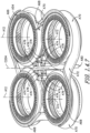
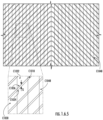
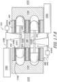
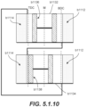
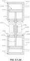
- FIG. 1.4.3 a side cutaway view of an embodiment of a pair of piston bodies C700 is provided.
- the embodiment depicted in regard to FIG. 1.4.3 is configured substantially similarly as shown and described in regard to FIGS. 1.4.1-1.4.2 .
- FIG. 1.4.3 further provides a partial cutaway view within the piston body C700 exposing a portion of the plurality of chiller conduits A54 between the volume walls A46, A48.
- the chiller conduit A54 extends along the lateral direction L between the chiller passage opening A58 and the chiller collection chamber A62.
- the chiller conduit A54 extends at least partially along an oblique or orthogonal direction relative to the lateral direction L.
- the chiller conduit A54 extends substantially circumferentially around the piston body C700.
- the chiller conduit A54 may extend at least partially along the oblique or orthogonal direction relative to the lateral direction L such as to desirably increase a surface area of the chiller passage A56 defined within the chiller conduit A54 at which the engine working fluid is in thermal communication with the chiller working fluid in the cold side heat exchanger A42.
- the desirable increase in surface area of the chiller passage A56 defined by the chiller conduit A54 provides the surrounding chiller working fluid in the first and second chiller working fluid passage A68, A70 to be in thermal communication so as to improve the opportunity for the transfer of thermal energy from the engine working fluid to the chiller working fluid.
- the surface area over which the engine working fluid is desirably in thermal communication with the surrounding chiller working fluid is desirably adjusted by adjusting the lateral, circumferential, or orthogonal extension of the chiller conduits A54 such as to adjust the heat exchanging surface area of the chiller passage A56.
- the chiller conduit A54 may extend at least partially in a curved or circumferential or spiral direction, such as a helix, between the chiller passage opening A58 and the chiller collection chamber A62.
- the chiller conduit A54 may extend in a zig-zag or serpentine pattern between the chiller passage opening A58 and the chiller collection chamber A62.
- other geometries may be defined such as to produce the desired heat exchanging surface area of the chiller conduit A54 relative to the chiller working fluid passage A66.
- the surface area of the chiller passage A56 defined within each chiller conduit A54 described herein corresponds to the chiller passage A56, such as an internal wall or surface of the chiller conduit A54 at which the engine working fluid is in direct contact.
- the surface area defines a nominal surface area of the chiller passage A56, such as a cross section of the chiller conduit A54.
- various embodiments further include a connecting chiller conduit A54 extended between the first piston body C700 and the second piston body C700.
- the connecting chiller conduit A54 provides fluid communication of the chiller working fluid between two or more piston bodies C700.
- the chiller working fluid passage A66 at each piston body C700 includes a first chiller working fluid passage A68 and a second chiller working fluid passage A70 each in thermal communication with the compression chamber A222.
- the second chiller working fluid passage A70 is positioned proximal to the chiller passage opening A58 at the compression chamber A222.
- the first chiller working fluid passage A68 is positioned distal to the chiller passage opening A58 at the compression chamber A222.
- the chiller working fluid may enter the chiller assembly A40 and flow at the first chiller working fluid passage A68 of one piston body C700 and the second chiller working fluid passage A70 of another piston body C700.
- the chiller working fluid may enter the chiller assembly A40 and flow in thermal communication with a generally hotter portion of one piston body C700 (i.e., proximate along the lateral direction L to the expansion chamber A221) and engine working fluid positioned proximal to the hot or expansion chamber A221.
- the chiller working fluid may then flow to another piston body C700 to a portion distal to the hot or expansion chamber A221 of the other piston body C700, such as may be generally cooler relative to first piston body C700.
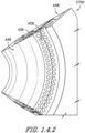
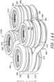
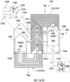
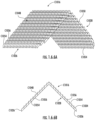
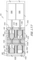
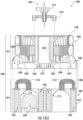
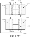
- FIG. 1.4.4 a perspective view of an exemplary embodiment of a portion of the engine A100 is provided. Referring additionally to FIGS. 1.4.5-1.4.6 , further embodiments of the portion of the engine A100 are provided.
- FIG. 1.4.4 includes a partial cutaway view within the piston body C700 exposing chiller conduits A54 between the volume walls A46, A48.
- FIG. 1.4.4 depicts at least a pair of the piston bodies C700 including the connecting chiller conduit A54 such as to provide fluid communication and thermal communication from the first chiller working fluid passage A68 of the first piston body C700 to the second chiller working fluid passage A70 of the second piston body C700.
- the second piston body C700 includes the connecting chiller conduit A54 providing fluid communication and thermal communication from the first chiller working fluid passage A68 of the second piston body C700 to another adjacent second chiller working fluid passage A70 of another adjacent piston body C700 different from the first piston body C700 and the second piston body C700.
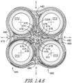
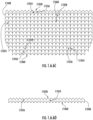
- FIG. 1.4.5 a top-down view of an exemplary embodiment of the portion of the engine depicted in FIG. 1.4.4 is provided.
- FIG. 1.4.6 a bottom-up view of an exemplary embodiment of the portion of the engine depicted in FIG. 1.4.4 is provided.
- the embodiments further depict the connecting chiller conduit A54 extended between pairs of the piston body C700.
- the engine includes a chiller working fluid inlet opening A78 through which chiller working fluid is provided to the chiller working fluid passage A66.
- the chiller working fluid inlet opening A78 may be positioned generally inward within the engine or proximal to the reference longitudinal axis C204.
- the chiller working fluid passage A66 may define a flowpath from the chiller working fluid inlet opening A78 and at least partially around one piston body C700.
- the flowpath may further extend across the connecting chiller conduit A54 to another or second piston body 84 adjacent or next to the first piston body 82.
- the flowpath of the chiller working fluid passage A66 further extends substantially circumferentially around the other piston body C700 (e.g., depicted at the second piston body C700).
- the flowpath is in fluid communication with a chiller working fluid outlet opening A80.
- the chiller working fluid outlet opening A80 is positioned outward or distal from the reference longitudinal axis C204.
- the flowpath of the chiller working fluid passage A66 extends from the chiller working fluid inlet opening A78 at least partially circumferentially around one piston body C700 and further across the connecting chiller conduit A54 to extend at least partially circumferentially, or substantially circumferentially, around another or adjacent piston body C700.
- the other or second piston body C700 includes the chiller working fluid opening and flowpath extended at least partially circumferentially to the connecting chiller conduit A54 to provide fluid communication and thermal communication to yet another piston body C700 and circumferentially around the yet another piston body C700 to the chiller working fluid outlet opening A80.
- the chiller working fluid inlet opening A78, the chiller working fluid outlet opening A80, or both extend at least partially along the lateral direction L or orthogonal to the flowpath of the chiller working fluid passage A66 such as to ingress and egress the chiller working fluid through the chiller working fluid passage A66.
- the engine includes the chiller working fluid inlet opening A78 corresponding to each piston body C700. Additionally, or alternatively, the engine includes the chiller working fluid outlet opening A80 corresponding to each piston body C700.
- the flowpath of the chiller working fluid passage A66 extends at least partially along the lateral direction L such as shown and described in regard to FIG. 1.4.3 .
- the flowpath arrangement shown and described in regard to FIGS. 1.4.3-1.4.7 provides thermal communication of the chiller working fluid with the engine working fluid, such as the engine working fluid within the chiller conduits A54 at each piston body C700.
- the piston bodies C700 distal to the chiller working fluid inlet opening A78 additionally are proximate to the chiller working fluid outlet opening A80.
- the shorter chiller working fluid flowpath provides the shorter flowpath from the piston body C700 proximate to the chiller working fluid outlet opening A80.
- the chiller working fluid flowpath A66 further provides the longer flowpath (relative to the first chiller working fluid flowpath) from the piston body C700 distal to the chiller working fluid outlet opening A80.
- the chiller conduit A54 is extended from the compression chamber A222 along a first lateral direction and extends along a second lateral direction opposite of the first lateral direction.
- the chiller conduit A54 includes an approximately 180 degree turn between the chiller passage opening A58 and the chiller collection chamber A62.
- the chiller working fluid passage A66 further surrounds the chiller conduit A54 along the lateral direction L.
- the chiller working fluid passage A66 further surrounds the 180 degree turn portion of the chiller conduit A54.
- the chiller passage openings A58 may generally be positioned such as to prevent the piston A1011 of the piston assembly A1010 from covering or otherwise obscuring the chiller passage openings A58 during operation of the system A10.
- chiller working fluid flowing through the chiller working fluid passage A66 may receive thermal energy from the engine working fluid within one or more of the chiller conduits A54.
- the rate or quantity of thermal energy transferring from the engine working fluid to the chiller working fluid within the chiller working fluid passage A66 may vary as between respective portions of the chiller working fluid passage A66, such as shown and described in regard to the first chiller working fluid passage A68 and the second chiller working fluid passage A70, and/or between respective piston bodies (e.g., the first piston body and the second piston body).
- the rate or quantity of thermal energy transferring from the engine working fluid to the chiller working fluid passage A66 may depend at least in part on a temperature gradient between the chiller conduit A54 and the chiller working fluid passage A66, such as a temperature gradient between the engine working fluid and the chiller working fluid.
- the engine working fluid within the plurality of chiller conduits A54 may exhibit a temperature that differs as between at least two piston bodies C700 (e.g., first piston body and second piston body) and/or as between at least two portions along the lateral extension of the chamber 222 (i.e., temperature gradient of the chamber 222 along the lateral direction L) within a given piston body.
- the engine working fluid within the plurality of piston bodies C700 may exhibit a temperature that differs as between at least two piston bodies.
- the engine working fluid within the plurality of chiller conduits A54 corresponding to one piston body e.g., the first piston body
- the plurality of chiller conduits A54 corresponding to another piston body e.g., the second piston body
- the temperature of the chiller working fluid may increase as the chiller working fluid flows through the chiller working fluid passage A66 and receives thermal energy from the engine working fluid within the chiller conduits A54.
- the chiller working fluid passage A66 extending at least partially circumferentially around one piston body (e.g., the first piston body), and further extended at least partially circumferentially around one or more other piston bodies (e.g., the second piston body) includes the chiller working fluid increasing in temperature by receiving thermal energy at one piston body.
- the second chiller working fluid passage A70 positioned distal to the expansion chamber A221 relative to the first chiller working fluid passage A68, may exhibit a lower temperature gradient between the engine working fluid and the chiller working fluid. Additionally, such as described herein , the chiller working fluid passage A66 at one piston body may exhibit a larger temperature gradient than another piston body to which the chiller working fluid passage A66 is thermally coupled (i.e., via the connecting chiller conduit A54), such as based on the cycle or stroke of the engine during operation.
- Operation of the engine A100 and system A10 includes the plurality of piston assemblies A1010 moving in cyclic operation, such as in back and forth movement between the piston body c700 at the first end A101 and another piston body c700 at the second end A102 ( FIG. 1.3.1 ). Pressure increases and decreases at respective chambers A221, A222 correspond to movement of the piston assemblies A1010, such as further described herein. In exemplary embodiments such as depicted in regard to FIG. 1.3.1 . or FIG. 1.7.1 through FIG.
- the plurality of piston bodies c700 may include the expansion chamber A221 and the compression chamber A222 defined at each end A101, A102 of each piston assembly A1010, such as to provide eight each of the expansion chamber A221 and the compression chamber A222 at four piston assemblies A1010.
- the plurality of piston assemblies A1010 may be disposed radially relative to the longitudinal axis C204.
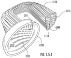
- the plurality of working fluid pathways C110 extend in fluid communication from a expansion chamber A221 to the walled conduit A1050.
- the working fluid pathways C110 extend in fluid communication from the expansion chamber A221 to a corresponding regenerator body C800 at the walled conduit A1050.
- a first plurality of heater conduits or working-fluid pathways C110 may fluidly communicate between an expansion chamber A221 defined by a first piston body C700 and a first compression chamber A222 defined by another piston body C700 different from the first piston body C700 (e.g., not the first piston body).
- a second plurality of working-fluid pathways C110 may fluidly communicate between a second expansion chamber A221 (i.e., different from the first expansion chamber) defined by a second piston body c700 and a compression chamber A222 defined by another piston body C700 (e.g., not the second piston body).
- Fluid communication between the expansion chamber A221 of one piston body C700 and the compression chamber A222 of another piston body C700 through the heater conduits or working fluid pathways C110 provides for the engine working fluid to be in thermal communication with the heating working fluid surrounding the working fluid pathways C110.
- the heating working fluid such as described herein, is provided in thermal and/or fluid communication around the working fluid pathways C110.
- the working fluid pathways C110 fluidly separate the heating working fluid and the engine working fluid while further providing heat transfer between the heating working fluid and the engine working fluid (e.g., heat transfer from the heating working fluid to the engine working fluid).
- the engine working fluid is heated at least at the working fluid pathways C110 and provides for pressure change at the respective expansion chamber A221 (e.g., pressure increase at the expansion chamber A221).
- pressure changes at the engine working fluid between the fluidly connected expansion chamber A221 and the compression chamber A222 via the heater conduit or working fluid pathways C110 correspond to heat transfer to the engine working fluid from the heating working fluid.
- heat transfer, or an amount of heat transferred, to the engine working fluid may be based on the engine cycle.
- the amount of heat transferred to the engine working fluid may correspond to whether the expansion chamber A221 is increasing in pressure or decreasing in pressure, or whether a corresponding fluidly connected compression chamber A222 is decreasing in pressure or increasing in pressure.
- regenerator bodies c800 may define part of the heater body c100 and/or an engine c002, such as shown and described in regard to system A10 and engine A100 herein, or further herein with reference to FIG. 4.1.1.
- a regenerator body c800 may define at least a portion of a monolithic body or a monolithic body-segment.
- Such monolithic body or monolithic body-segment may define at least a portion of the heater body c100 and/or the engine c002.
- regenerator bodies c800 may be provided as a separate component, whether for use in connection with a heater body c100, an engine c002, or any other setting whether related or unrelated to a heater body c100 or an engine c002. It will be appreciated that an engine c002 and/or a heater body c100 may include any desired number of regenerator bodies c800.
- the plurality of working-fluid pathways c110 may extend between respective ones of a plurality of piston chamber apertures c111 and respective ones of a plurality of regenerator apertures c113.
- the piston chamber apertures c111 provide fluid communication between the working-fluid pathways c110 and the piston chamber c112, and the regenerator apertures c113 provide fluid communication between the working-fluid pathways c110 and the regenerator conduit c1000.
- the piston chamber apertures c111 may define a first end of the working-fluid pathways c110 and the regenerator apertures c113 may define a second end of the working-fluid pathways c110.
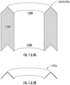
- a piston body c700 may define a hot-side c1002 of the piston chamber c112 and a cold side piston chamber c1004.
- a regenerator conduit c1000 may include a hot-side portion c1006 and a cold-side portion c1008.
- a plurality of hot-side working-fluid pathways c1010 may provide fluid communication between the regenerator body c800 and a first piston body c700, such as between the hot-side portion c1006 and the hot-side c1002 of the piston chamber c112.
- a plurality of cold-side working-fluid pathways c1010 may provide fluid communication between the regenerator body c800 and a second piston body c700, such as between the cold-side regenerator conduit c1008 the cold-side c1004 of the piston chamber c112.
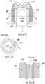
- an exemplary regenerator conduit c1000 may include an annular sidewall c1020.
- the annular sidewall c1020 may circumferentially surround the heat storage medium c1014, such as the plurality of fin arrays c1016.
- a regenerator conduit c1000 may define an annulus.
- the regenerator conduit c1000 may include a radially outward annular sidewall c1022 and a radially inward annular sidewall c1024.
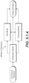
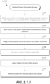
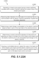
- the exemplary method c1070 may include, at block 1074, transferring heat from the engine-working fluid to the plurality of fin arrays c1016.
- the plurality of fin arrays c1016 may be respectively supported by the regenerator conduit c1000 in spaced relation to one another.
- the spaced relation of the plurality of fin arrays c1016 may define a gap G 1018 longitudinally separating adjacent ones of the plurality of fin arrays c1016.
- the exemplary method c1070 may further include, at block 1076, flowing the engine-working fluid from the cold-side portion c1008 of the regenerator body c800 towards the hot-side portion c1006 of the regenerator body c800.
- the exemplary method c1070 may include transferring heat from the plurality of fin arrays c1016 to the engine-working fluid.
- the piston bodies C700 may generally define cylinders into which pistons A1011 of the piston assembly A1010 are each positioned such as to define the expansion chamber A221 and the compression chamber A222 within each piston body C700.
- pistons A1011 of the piston assembly A1010 are each positioned such as to define the expansion chamber A221 and the compression chamber A222 within each piston body C700.
- other suitable geometries of the piston body C700 containing the piston A1011 may be utilized.
- the engine A100 further includes a plurality of walled conduits A1050 connecting particular chambers A221, A222 of each piston body C700 ( FIG. 1.3.1 ) such as to define a balanced pressure arrangement of the pistons A1011.
- the engine A100 includes at least one interconnected volume of chambers A221, A222 such as described herein. In one embodiment, such as depicted in regard to FIGS. 1.7.1 - FIG.
- the fluidly separated and/or pneumatically separated arrangement of chambers A221, A222 into the interconnected volume, and those chambers A221, A222 outside of the interconnected volume or in another interconnected volume, is particularly provided via the arrangement of expansion chambers A221 connected to compression chambers A222 via the walled conduits A1050 such as further described herein.
- the interconnected volume includes pairs of the expansion chamber A221 fluidly coupled to the compression chamber A222 each defined at laterally separated ends of the piston assemblies A1010.
- the engine A100 defines a first end 101 separated along the lateral direction L by the connection member A1030 from a second end 102, such as depicted in FIG. 1.7.2 and FIG. 1.7.3 .
- Each end of the engine A100 defines an expansion chamber A221 and a compression chamber A222 at each piston A1011 of each piston assembly A1010.
- the engine A100 depicted in FIGS. 1.7.1 - FIG. 1.7.4 , and further in regard to FIG. 1.3.1 includes the expansion chamber A221 at one end connected to a respective compression chamber A222 at another end via respective conduits.
- the engine A100 includes two expansion chambers A221 at the first end 101 each connected to respective compression chambers A222 at the second end 102 via respective conduits A1050.
- the engine A100 further includes two expansion chambers A221 at the second end 102 each connected to respective compression chamber A222 at the first end 101 via respective conduits A1050.
- the system A10 further includes four expansion chambers A221 at one end each connected to respective compression chambers A222 at the same end via respective conduits A1050.
- the system A10 includes two expansion chambers A221 at the first end 101 each connected to respective compression chambers A222 at the first end 101 via respective walled conduits A1050.
- the system A10 further includes two expansion chambers A221 at the second end 102 each connected to respective compression chambers A222 at the second end 102 via respective walled conduits A1050.
- the expansion chamber A221 at the first end 101 is fluidly connected to the compression chamber A222 at the same end (i.e., the first end 101).
- the expansion chamber A221 at the second end 102 is fluid connected to the compression chamber A222 at the same end (i.e., the second end 102).
- the expansion chamber A221 at the first end 101 is fluidly connected to the compression chamber A222 at the second end 102 (i.e., the opposing end).
- the expansion chamber A221 at the second end 102 is fluidly connected to the compression chamber at the first end 101 (i.e., the opposing end).
- each expansion chamber A221 of one piston body C700 of one piston assembly A1010 connected to a respective compression chamber A222 of another, different piston body C700 of another, different piston assembly A1010. It should further be appreciated that, in various embodiments, the expansion chamber A221 of one piston body C700 and one piston assembly C1010 is exclusively fluidly connected to the compression chamber A222 of another piston body C700 of another piston assembly C1010 (i.e., each walled conduit A1050 fluidly connects only one expansion chamber A221 to only one compression chamber A222).
- the balanced pressure arrangement of piston assemblies A1010 described herein is such that a uniform temperature applied at the expansion chambers A221 and the compression chambers A222 provides an equal pressure at the expansion chamber A221 of one piston body C700 counteracted by an equal and opposite pressure at the same piston body C700 relative to the expansion chamber A221.
- a uniform temperature is applied to the expansion chambers A221 and the compression chambers A222, movement of one piston assembly A1010 defining a free piston assembly A1010 results in pressure cancellation at adjacent piston assemblies A1010 such that pressure waves will not propagate to induce movement of the adjacent piston assembly A1010.
- each interconnected volume described herein includes one or more passages, chambers, openings, or other flowpaths between the arrangements of the compression chamber A222 and the expansion chamber A221 described above.
- the particular arrangements of walled conduits A1050 providing fluid communication of the engine working fluid between the compression chamber A222 and the expansion chamber A221 such as described in regard to FIGS. 1.7.1 through 1.7.4 further includes the chiller conduits A54, collection chambers A62, A64, heater conduits C110, etc. such as shown and described in regard to FIG. 1.4.1 through FIG. 1.5.1 .
- the particular arrangements of walled conduits A1050 providing fluid communication between the compression chamber A222 and the expansion chamber A221 such as described in regard to FIG. 1.7.1 through FIG. 1.7.2 may further include a heat exchanger or regenerator, or features thereof, such as shown and described in regard to FIG. 1.6.1 .
- the engine A100 generally includes an interconnected volume such as described above.
- other embodiments of the engine A100 may include a quantity of two or more piston assemblies A1010 in which the arrangements of the piston assembly A1010 are scaled accordingly based on the arrangement described above such as to provide at least one interconnected volume of chambers A221, A222 and conduits 1050.
- the engine includes four piston assemblies A1010 extended along the lateral direction L and in circumferential arrangement relative to the reference longitudinal axis C204.
- the piston assemblies A1010 may be positioned equidistant to one another around the reference longitudinal axis C204.
- a pair of the heater body is positioned at outer ends A103 of the engine.
- the heater body is positioned proximate to the expansion chamber A221 and distal to the compression chamber A222.
- Each heater body may be positioned and configured to provide a substantially even flow of thermal energy to four hot side heat exchangers 160 or expansion chambers A221 at a time.
- an engine assembly c900 may include only two monolithic bodies or monolithic body-segments, while in other embodiments an engine assembly c900 may include more than two (e.g., multiple) monolithic bodies or monolithic body-segments.
- the second piston body c944 may include a second regenerator body c952 and/or a second chiller body c954.
- the second heater body c930 and/or the second engine body c932 may include a second regenerator body c952.
- the second heater body c930 and/or the second engine body c932 may additionally or alternatively include a second chiller body c954.
- the second regenerator body c952 may define a portion of the second piston body c944 or at least a portion of a monolithic body-segment operably coupled or operably couplable to the second piston body c944.
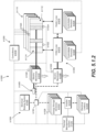
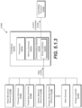
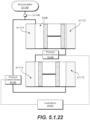
- an engine assembly c900 may include a plurality of monolithic bodies or monolithic body-segments, such as a first monolithic body or monolithic body-segment c908 defining a first heater body c902 and a first engine body c904, a second monolithic body or monolithic body-segment c936 defining a second heater body c930 and a second engine body c932, and a third monolithic body or monolithic body-segment c962 defining a third engine body c960.
- a first monolithic body or monolithic body-segment c908 defining a first heater body c902 and a first engine body c904
- a second monolithic body or monolithic body-segment c936 defining a second heater body c930 and a second engine body c932
- a first monolithic body c908 may include a first heater body c902, a first engine body c904, and a first piston body c916.
- the first heater body c902 may define a first portion c906 of a first monolithic body c908.
- the first engine body c904 may define a second portion c910 of the first monolithic body c908.
- the first heater body c902 may define at least a portion of the first monolithic body c908 and/or the first engine body c904 may define at least a portion c910 of a second monolithic body c936.
- the first engine body c904 may include a first piston body c916 defining a third portion c920 of the first monolithic body c908 and/or a third portion c920 of the first engine body c904.
- the first piston body c916 may define at least a portion of a piston chamber c112.
- the piston chamber c112 may be configured to receive at least a portion of a piston assembly c090.
- the first heater body c902 and/or the first engine body c904 may include a first regenerator body c926.
- the first piston body c916 may include a first regenerator body c926 and/or a first chiller body c928.
- the first heater body c902 and/or the first engine body c904 may additionally or alternatively include a first chiller body c928.
- the first regenerator body c926 may define a portion of the first piston body c916 or at least a portion of a monolithic body-segment operably coupled or operably couplable to the first piston body c916.
- the first chiller body c928 may define a portion of the first piston body c916 or at least a portion of a monolithic body-segment operably coupled or operably couplable to the first piston body c916.
- the first regenerator body c926 may define a fifth portion of the first monolithic body c908 and/or the first chiller body c928 may define a sixth portion of the first monolithic body c908.
- an exemplary engine assembly c900 may additionally or alternatively include a second heater body c930 and/or a second engine body c932.
- the second heater body c930 may define a first portion c934 of a second monolithic body c936.
- the second engine body c932 may define a second portion c938 of the second monolithic body c936.
- the second engine body c932 may include a second piston body c944.
- the second piston body c944 may define a third portion c948 of the second monolithic body c936 and/or a third portion c948 of the second engine body c932.
- the second piston body c944 may define at least a portion of a piston chamber c112.
- the piston chamber c112 may be configured to receive at least a portion of a piston assembly c090.
- the second piston body c944 may include a second regenerator body c952 and/or a second chiller body c954.
- the second heater body c930 and/or the second engine body c932 may include a second regenerator body c952.
- the second heater body c930 and/or the second engine body c932 may additionally or alternatively include a second chiller body c954.
- the second regenerator body c952 may define a portion of the second piston body c944 or at least a portion of a monolithic body-segment operably coupled or operably couplable to the second piston body c944.
- the second chiller body c954 may define a portion of the second piston body c944 or at least a portion of a monolithic body-segment operably coupled or operably couplable to the second piston body c944.
- the second regenerator body c952 may define a fifth portion of the second monolithic body c936 and/or the second chiller body c928 may define a sixth portion of the second monolithic body c936.
- the second regenerator body c952 and/or the second chiller body c954 may define a monolithic body-segment operably coupled or operably couplable to the second monolithic body c936.
- an engine assembly c900 may include a third engine body c960.
- the third engine body c960 may define at least a portion of a third monolithic body or monolithic body-segment c962.
- the third engine body c960 may be operably couplable to the first engine body c904 and/or the second engine body c932.
- the third engine body c960 may include a third machine body c964.
- the third machine body c964 may define a first portion c972 of the third monolithic body c962 or at least a portion of a monolithic body-segment.
- the third machine body c964 may define at least a portion of a generator housing c919.
- the generator housing c919 may be configured to receive at least a portion of a load device c092.
- the third machine body c964 may be operably coupled or operably couplable to the first engine body c904 and/or the second engine body c932.
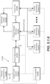
- an engine assembly c900 may include a plurality of monolithic bodies or monolithic body-segments, such as a first monolithic body or monolithic body-segment c908 defining a first heater body c902 and a first engine body c904, a second monolithic body or monolithic body-segment c936 defining a second heater body c930 and a second engine body c932, a third monolithic body or monolithic body-segment c962 defining a third engine body c960, and a fourth monolithic body or monolithic body-segment c978 defining a fourth engine body c976.
- a first monolithic body or monolithic body-segment c908 defining a first heater body c902 and a first engine body c904
- a second monolithic body or monolithic body-segment c936 defining a second heater body
- the first engine body c904 may include a first piston body c916 defining a third portion c920 of the first monolithic body c908 and/or a third portion c920 of the first engine body c904.
- the first piston body c916 may define at least a portion of a piston chamber c112.
- the piston chamber c112 may be configured to receive at least a portion of a piston assembly c090.
- the first heater body c902 and/or the first engine body c904 may include a first regenerator body c926.
- the first piston body c916 may include a first regenerator body c926.
- the first regenerator body c926 may define a portion of the first piston body c916 or at least a portion of a monolithic body-segment operably coupled or operably couplable to the first piston body c916.
- the first regenerator body c926 may define a fifth portion of the first monolithic body c908.
- an exemplary engine assembly c900 may additionally or alternatively include a second heater body c930 and/or a second engine body c932.
- the second heater body c930 may define a first portion c934 of a second monolithic body c936.
- the second engine body c932 may define a second portion c938 of the second monolithic body c936.
- the second engine body c932 may include a second piston body c944.
- the second piston body c944 may define a third portion c948 of the second monolithic body c936 and/or a third portion c948 of the second engine body c932.
- the second piston body c944 may define at least a portion of a piston chamber c112.
- the piston chamber c112 may be configured to receive at least a portion of a piston assembly c090.
- the second piston body c944 may include a second regenerator body c952.
- the second heater body c930 and/or the second engine body c932 may include a second regenerator body c952.
- the second regenerator body c952 may define a portion of the second piston body c944 or at least a portion of a monolithic body-segment operably coupled or operably couplable to the second piston body c944.
- the second regenerator body c952 may define a fifth portion of the second monolithic body c936 and/or. Additionally, or in the alternative, the second regenerator body c952 may define a monolithic body-segment operably coupled or operably couplable to the second monolithic body c936.
- an engine assembly c900 may include a third engine body c960 and a fourth engine body c976.
- the third engine body c960 may define at least a portion of a third monolithic body or monolithic body-segment c962.
- the third engine body c960 may be operably coupled or operably couplable to the first engine body c904 and/or the fourth engine body c976.
- the third engine body c960 may include a third machine body c964 and/or a third piston body c966.
- an engine body c904 may include a first piston body c916, a first regenerator body c926, and a working-fluid heat exchanger body c988 that includes a plurality of working-fluid pathways c110 fluidly communicating between the first piston body c916 and the first regenerator body c926.
- the working-fluid heat exchanger body c988 may define at least a portion of the first heater body c902 and/or at least a portion of the first engine body c904.
- the working-fluid heat exchanger body c988 may additionally or alternatively include a heating chamber body c990.
- the working-fluid heat exchanger body c988 may define at least a portion of the second monolithic body-segment c914.
- the heating chamber body c990 may surround at least a portion of the working-fluid heat exchanger body c988.
- the heating chamber body c990 may define at least a portion of a recirculation pathway c104 surrounding at least a portion of the working-fluid heat exchanger body c988.
- the heating chamber body c990 may fluidly communicate at an upstream portion (e.g., at a radially inward portion) with a heating fluid inlet c992.
- the second fuel injector body may include a second combustor cap c210 monolithically integrated with the second heater body c930.
- the second fuel injector body c401 may include a second combustor cap c210 operably coupled or operably couplable to the second heater body c930.
- a first fuel nozzle c214 may be monolithically integrated with first combustor cap c210.
- a first fuel nozzle c214 may be operably coupled or operably couplable to the first combustor cap c210.
- a second fuel nozzle c214 may be monolithically integrated with second combustor cap c210.
- a second fuel nozzle c214 may be operably coupled or operably couplable to the second combustor cap c210.
- a first piston assembly c090 may be operably inserted or operably insertable into a first piston chamber c112 and/or a second piston assembly c090 may be operably inserted or operably insertable into a second piston chamber c112.
- a first load device c092 may be operably inserted or operably insertable into a first generator housing c919 and/or a second load device c092 may be operably inserted or operably insertable into a second generator housing c919.
- an exemplary method c4000 may include, at block c4002, coupling a first monolithic body c908 or a first monolithic body-segment c912 to a second monolithic body c936 or a second monolithic body segment c914.
- the first monolithic body c908 or the first monolithic body-segment c914 may have been additively manufactured and/or the second monolithic body c936 or the second monolithic body-segment c914 may have been additively manufactured.
- the first monolithic body c908 or the first monolithic body-segment c912 may include a first heater body c902 and/or a first engine body c904.
- the second monolithic body c936 or the second monolithic body-segment c914 may include a second heater body c930 and/or a second engine body c932.
- the first monolithic body c908 or the first monolithic body-segment c912 may include a first piston assembly c090 and/or a first load device c092 installed therein.
- the second monolithic body c936 or the second monolithic body-segment c914 may include the first piston assembly c090 and/or the first load device c092 installed therein.
- An exemplary method 1000 may include, at block c4004, additively manufacturing the first monolithic body c908 or the first monolithic body-segment c912.
- Additively manufacturing the first monolithic body c908 or the first monolithic body-segment c912 may include additively manufacturing the first heater body c902 and/or the first engine body c904.
- An exemplary method 1000 may include, at block c4006, installing the first piston assembly c090 and/or the first load device c092 in the first monolithic body c908 or the first monolithic body-segment c912.
- the method 1000 may include installing the first piston assembly c090 in the first heater body c902 and/or in the first engine body c904. Additionally, or in the alternative, the method 1000 may include installing the first load device c092 in the first heater body c902 and/or in the first engine body c904.
- An exemplary method 1000 may include, at block c4008, additively manufacturing the second monolithic body c936 or the second monolithic body-segment c914.
- Additively manufacturing the second monolithic body c936 or the second monolithic body-segment c914 may include additively manufacturing the second heater body c930 and/or the second engine body c932.
- An exemplary method 1000 may include, at block c4010, installing the first piston assembly c090 and/or the first load device c092 in the second monolithic body c936 or the second monolithic body-segment c914.
- the method 1000 may include installing the first piston assembly c090 in the second heater body c930 and/or the second engine body c932. Additionally, or in the alternative, the method 1000 may include installing the first load device c092 in the second heater body c930 and/or the second engine body c932.
- An exemplary method 1000 may include, at block c4012, additively manufacturing a first piston body c916.
- the first piston body c916 may define at least a portion of the first monolithic body c908 or at least a portion of the first monolithic body-segment c912. Additionally, or in the alternative, the first piston body c916 may define at least a portion of the second monolithic body c936 or at least a portion of the second monolithic body-segment c914.
- the exemplary method c4000 may additionally or alternatively include installing the first piston assembly c090 in the first piston body c916.
- the exemplary method 1000 may additionally or alternatively include, at block c4014, additively manufacturing a first machine body c922.
- the first machine body c922 may define at least a portion of the first monolithic body c908 or at least a portion of the first monolithic body-segment c912. Additionally, or in the alternative, the first machine body c922 may define at least a portion of the second monolithic body c936 or at least a portion of the second monolithic body-segment c912.
- the exemplary method c4000 may additionally or alternatively include installing the first load device c092 in the first machine body c922.
- the exemplary method 1000 may additionally or alternatively include, at block c4016, additively manufacturing a first regenerator body c926.
- the first regenerator body c926 may define at least a portion of the first monolithic body c908 or at least a portion of the first monolithic body-segment c912. Additionally, or in the alternative, the first regenerator body c926 may define at least a portion of the second monolithic body c936 or at least a portion of the second monolithic body-segment c912.
- the exemplary method c4000 may additionally or alternatively include installing the first regenerator body c926 in the first monolithic body c908 or at least a portion of the first monolithic body-segment c912.
- the exemplary method 1000 may additionally or alternatively include, at block c4018, additively manufacturing a first chiller body c928.
- the first chiller body c928 may define at least a portion of the first monolithic body c908 or at least a portion of the first monolithic body-segment c912. Additionally, or in the alternative, the first chiller body c928 may define at least a portion of the second monolithic body c936 or at least a portion of the second monolithic body-segment c912.
- the exemplary method c4000 may additionally or alternatively include installing the first chiller body c928 in the first monolithic body c908 or at least a portion of the first monolithic body-segment c912.
- additive manufacturing techniques or processes refer generally to manufacturing processes wherein successive layers of material(s) are provided on each other to “build-up,” layer-by-layer, a three-dimensional component. The successive layers generally fuse together to form a monolithic component which may have a variety of integral sub-components.
- additive manufacturing technology is described herein as providing fabrication of complex objects by building objects point-by-point, layer-by-layer, typically in a vertical direction, other methods of fabrication are possible and are within the scope of the present subject matter.
- embodiments of the present disclosure may use layer-additive processes, layer-subtractive processes, or hybrid processes.
- embodiments of the present disclosure may include selectively depositing a binder material to chemically bind portions of the layers of powder together to form a green body article. After curing, the green body article may be pre-sintered to form a brown body article having substantially all of the binder removed, and fully sintered to form a consolidated article.
- Suitable additive manufacturing techniques in accordance with the present disclosure include, for example, Fused Deposition Modeling (FDM), Selective Laser Sintering (SLS), 3D printing such as by inkjets and laserjets, Sterolithography (SLA), Direct Laser Sintering (DLS), Direct Selective Laser Sintering (DSLS), Electron Beam Sintering (EBS), Electron Beam Melting (EBM), Laser Engineered Net Shaping (LENS), Laser Net Shape Manufacturing (LNSM), Direct Metal Deposition (DMD), Digital Light Processing (DLP), Direct Laser Melting (DLM), Direct Selective Laser Melting (DSLM), Selective Laser Melting (SLM), Direct Metal Laser Melting (DMLM), Binder Jetting (BJ), and other known processes.
- FDM Fused Deposition Modeling
- SLS Selective Laser Sintering
- 3D printing such as by inkjets and laserjets
- SLA Sterolithography
- DLS Direct Laser Sintering
- DSLS Direct Selective Laser Sintering
- the additive manufacturing processes described herein may be used for forming components using any suitable material.
- the material may be plastic, metal, concrete, ceramic, polymer, epoxy, photopolymer resin, or any other suitable material that may be in solid, liquid, powder, sheet material, wire, or any other suitable form or combinations thereof.
- the additively manufactured components described herein may be formed in part, in whole, or in some combination of materials including but not limited to pure metals, nickel alloys, chrome alloys, titanium, titanium alloys, magnesium, magnesium alloys, aluminum, aluminum alloys, and nickel or cobalt based superalloys (e.g., those available under the name Inconel ® available from Special Metals Corporation). These materials are examples of materials suitable for use in the additive manufacturing processes described herein, and may be generally referred to as "additive materials.”
- references to "fusing" or “binding” may refer to any suitable process for creating a bonded layer of any of the above materials.
- fusing may refer to creating a thermoset bond between polymer materials.
- the bond may be formed by a crosslinking process.
- the bond may be formed by a sintering process.
- the bond may be formed by a melting or sintering process, or additionally with a binder process.
- the additive manufacturing process disclosed herein allows a single component to be formed from multiple materials.
- the components described herein may be formed from any suitable mixtures of the above materials.
- a component may include multiple layers, segments, or parts that are formed using different materials, processes, and/or on different additive manufacturing machines.
- components may be constructed which have different materials and material properties for meeting the demands of any particular application.
- the components described herein are constructed entirely by additive manufacturing processes, it should be appreciated that in alternate embodiments, all or a portion of these components may be formed via casting, machining, and/or any other suitable manufacturing process. Indeed, any suitable combination of materials and manufacturing methods may be used to form these components.
- Additive manufacturing processes fabricate components using three-dimensional (3D) information, for example a three-dimensional computer model, of the component.
- 3D three-dimensional
- a three-dimensional design model of the component may be defined prior to manufacturing.
- a model or prototype of the component may be scanned to determine the three-dimensional information of the component.
- a model of the component may be constructed using a suitable computer aided design (CAD) program to define the three-dimensional design model of the component.
- CAD computer aided design
- the components described herein may be fabricated using the additive process, or more specifically each layer is successively formed, e.g., by fusing or polymerizing a plastic using laser energy or heat or by sintering or melting metal powder.
- a particular type of additive manufacturing process may use an energy beam, for example, an electron beam or electromagnetic radiation such as a laser beam, to sinter or melt a powder material.
- Any suitable laser and laser parameters may be used, including considerations with respect to power, laser beam spot size, and scanning velocity.
- the build material may be formed by any suitable powder or material selected for enhanced strength, durability, and useful life, particularly at high temperatures.
- post processing procedures may include removal of excess powder by, for example, blowing or vacuuming.
- Other post processing procedures may include a stress relief process.
- thermal, mechanical, and/or chemical post processing procedures can be used to finish the part to achieve a desired strength, surface finish, a decreased porosity decreasing and/or an increased density (e.g., via hot isostatic pressing), and other component properties or features.
- multi-part components may be formed as a single piece of continuous metal, and may thus include fewer sub-components and/or joints compared to prior designs.
- the integral formation of these multi-part components through additive manufacturing may advantageously improve the overall assembly process, reduce potential leakage, reduce thermodynamic losses, improve thermal energy transfer, or provide higher power densities.
- the integral formation reduces the number of separate parts that must be assembled, thus reducing associated time, overall assembly costs, reduces potential leakage pathways, or reduces potential thermodynamic losses.
- existing issues with, for example, leakage may advantageously be reduced.
- joint quality between separate parts may be addressed or obviated by the processes described herein, such as to desirably reduce leakage, assembly, and improve overall performance.
- additive manufacturing methods described above provide much more complex and intricate shapes and contours of the components described herein to be formed with a very high level of precision.
- such components may include thin additively manufactured layers, cross sectional features, and component contours.
- additive manufacturing may provide heat exchanger surface areas, volumes, passages, conduits, or other features that may desirably improve heat exchanger efficiency or performance, or overall engine or system performance.
- the additive manufacturing process provides the manufacture of a single component having different materials such that different portions of the component may exhibit different performance characteristics. The successive, additive steps of the manufacturing process provide the construction of these novel features. As a result, the components described herein may exhibit improved functionality and reliability.
- Closed-cycle engine arrangements such as Stirling engines, generally define a ratio of power output in Watts to a product of mean average engine working fluid pressure in Pascals, swept volume of the engine working fluid in cubic meters, and engine cycle frequency in Hertz (i.e., operating frequency of a piston assembly), otherwise referred to as a Beale number.
- a maximum operating Beale number for Stirling engines generally ranges between 0.05 and 0.15.
- features, arrangements, ratios, or methods of manufacture and assembly shown and described herein provide the engine A100 to define a first operational parameter in which the first operational parameter defines a maximum operational Beale number greater than or equal to 0.10.
- the engine A100 defines a maximum operational Beale number greater than 0.15. In still another embodiment, the engine A100 defines a maximum operational Beale number greater than 0.20. In yet another embodiment, the engine A100 defines a maximum operational Beale number greater than 0.23. In various embodiments, the engine A100 defines a maximum operational Beale number less than or equal to 0.35. In still various embodiments, the engine A100 defines a maximum operational Beale number less than 0.30. In one embodiment, embodiments of the engine A100 shown and described herein define a maximum operational Beale number between 0.10 and 0.35, inclusive. In still various embodiments, the engine A100 defines a maximum operational Beale number between 0.15 and 0.30.
- Embodiments of the system A10 and engine A100 provided herein provide greater Beale numbers via one or more of the features, arrangements, ratios, or methods of manufacture and assembly provided herein. Greater Beale numbers are provided at least in part via lower average engine working fluid pressure, lower engine cycle frequency of the piston assemblies A1010, or lower swept volume of the engine working fluid between fluidly connected chambers A221, A222, or combinations thereof, relative to the power output from the piston assembly A1010. Exemplary embodiments of the system A10 and engine A100 provided herein may produce a mechanical power output from the piston assembly A1010 up to 100 kilowatts (kW) or more.
- kW kilowatts
- Embodiments of the engine A100 provided herein may provide greater Beale numbers based at least in part on the plurality of heater conduits C110 collectively defining a desired heat transferability of thermal energy from the hot side heat exchanger C108 to the engine working fluid within the plurality of heater conduits C110.
- the system A10 defines a ratio of maximum cycle volume of the engine working fluid to a collective volume of the plurality of heater conduits.
- the maximum cycle volume is the maximum volume of the engine working fluid within the expansion chamber A221, the compression chamber A222, and the fluid volume connected therebetween (e.g., the expansion chamber A221 of one piston body and the compression chamber A222 of another piston body connected by the walled conduit A1050).
- the minimum cycle volume is the minimum volume of the engine working fluid within the expansion chamber A221, the compression chamber A222, and the fluid volume connected therebetween (e.g., the expansion chamber A221 of one piston body and the compression chamber A222 of another piston body connected by the walled conduit A1050).
- the difference between the maximum cycle volume and the minimum cycle volume is the swept volume.
- the ratio of maximum cycle volume of the engine working fluid to the volume of the passages within the plurality of heater conduits is between 2.5 and 25.
- the plurality of heater conduits together contain between two-fifths and one-twenty-fifth of the volume of the total volume of engine working fluid based on the maximum cycle volume. Stated differently, between two-fifths and one-twenty-fifth of the maximum cycle volume of the engine working fluid is receiving thermal energy from the hot side heat exchanger C108 during operation of the system A10.
- embodiments of the engine A100 provided herein may provide greater Beale numbers based at least in part on a ratio of surface area of the plurality of heater conduits C110 versus volume of the working fluid within the plurality of heater conduits C110.
- the plurality of heater conduits may provide a range of surface area collectively within the plurality of heater conduits C110 relative to the volume of the engine working fluid within the plurality of heater conduits C110.
- the surface area may generally define the internal area of the heater conduits in direct fluid contact with the engine working fluid.
- the ratio of surface area of the plurality of heater conduits to volume of the working fluid within the plurality of heater conduits is between 8 and 40.
- the plurality of heater conduits together defines a unit surface area within the conduits (i.e., surface area in fluid contact with the engine working fluid) between 8 and 40 times greater than a unit volume of the plurality of heater conduits.
- the internal surface area of the plurality of heater conduits is defined between a first opening and a second opening of the heater conduits C110.
- the first opening is in direct fluid communication with the expansion chamber A221, such as depicted at the piston chamber aperture C111 in FIG. 1.5.1 .
- the second opening is in direct fluid communication with the walled conduit C1050, such as depicted at the opening C113 in FIG. 1.5.1 .
- the second opening is in direct fluid communication with the walled conduit C1050 including the regenerator body C800 defined therewithin.
- the surface area of the plurality of heater conduits C110 defines an internal area of the heater conduits C110 corresponding to portions of the heater conduits C110 receiving thermal energy from the heater body C100.
- the surface area of the plurality of heater conduits C110 defines an internal area of the heater conduits C110 extending from a first opening, such as defined at the plurality of piston apertures C111 in FIG. 1.5.1 , to a first or proximal fin, tab, wall, or other feature of the fin array C1016 of the regenerator body C800 at the walled conduit C1050.
- the second opening such as depicted at opening C113 in FIG. 1.5.1 ., is in direct fluid communication with chiller collection chamber A62 or the chiller conduits A54.
- the second opening such as depicted at opening C113 in FIG. 1.5.1 ., is in direct fluid communication with the chiller collection chamber opening A60.
- Embodiments of the engine A100 provided herein may provide greater Beale numbers based at least in part on the plurality of chiller conduits A54 collectively defining a desired heat transferability of thermal energy from the engine working fluid within the plurality of chiller conduits A54 to the cold side heat exchanger A42.
- the system A10 defines a ratio of maximum cycle volume of the engine working fluid to a collective volume of the plurality of chiller conduits A54. In one embodiment, the ratio of maximum cycle volume of the engine working fluid to the volume of the plurality of chiller conduits A54 is between 10 and 100.
- the plurality of chiller conduits A54 together contain between one-tenth and one-hundredth of the volume of the total volume of engine working fluid based on the maximum cycle volume. Stated differently, between one-tenth and one-hundredth of the maximum cycle volume of the engine working fluid is transferring thermal energy to the cold side heat exchanger A42 during operation of the system A10.
- embodiments of the engine provided herein may provide greater Beale numbers based at least in part on a ratio of surface area of the plurality of chiller conduits A54 versus volume of the working fluid within the plurality of chiller conduits A54.
- the plurality of chiller conduits A54 may particularly provide a range of surface area collectively within the plurality of chiller conduits A54 relative to the volume of the engine working fluid within the plurality of chiller conduits A54.
- the ratio of surface area of the plurality of chiller conduits A54 to volume of the working fluid within the plurality of chiller conduits A54 is between 7 and 40.
- the plurality of chiller conduits A54 together defines a unit surface area within the conduits (i.e., surface area in fluid contact with the engine working fluid) between 7 and 40 times greater than a unit volume of the plurality of chiller conduits A54.
- Efficiencies described herein may include T Hot,engine corresponding to temperature input to the engine working fluid at the heater conduits or working fluid pathways C110 from the hot side heat exchanger C108.
- Still various embodiments include T Cold,ambient corresponding to temperature removed from the engine working fluid at the chiller conduits A54 to the cold side heat exchanger A42.
- the temperature input may alternatively correspond to heat or thermal energy input to the engine working fluid, such as from the heating working fluid.
- the temperature removed may alternatively correspond to heat or thermal energy output from the engine working fluid, such as to the chiller working fluid.
- the environment is the chiller working fluid into which the engine A100 rejects, exhausts, or otherwise releases heat or thermal energy from the engine working fluid at the chiller conduits A54.
- efficiencies described herein may include Q Out corresponding to thermal energy received by the engine working fluid at the heater conduits or working fluid pathways C110 from the hot side heat exchanger C108. Still various embodiments include Q In corresponding to thermal energy received at the chiller working fluid at the chiller working fluid passage A56 at the cold side heat exchanger A42 from the engine working fluid at the chiller conduits A54.
- E out is the net electrical energy output from the load device C092 that is operatively coupled to the engine A100 via the piston assembly C1010.
- the system A10 provides a temperature differential via the heater body C100 and the chiller assembly C40 in which the engine A100 generates mechanical power output between 1 kW and 100 kW relative to the piston assembly A1010.
- the system A10 is configured to generate between 10 kW and 100 kW.
- the system A10 is configured to generate between 25 kW and 100 kW.
- the system A10 may be configured to produce greater than 100 kW.
- the system A10 may include a plurality of the engine A100 operably coupled at two or more piston assemblies A1010 and the load device c092 to produce greater than 100 kW.
- a plurality of the engine A100 may be operably coupled to produce up to 5 megawatts.
- the engine A100 further defines a second operational parameter defining a ratio of mechanical power output from the piston assembly A1010 to maximum cycle volume of the working fluid between 0.0005 and 0.0040 kW per cubic centimeter (cc) for a given efficiency.
- the ratio of mechanical power output from the piston assembly A1010 to maximum cycle volume of the working fluid is a range of maximum ratio at which the mechanical power output from the piston assembly A1010 to maximum cycle volume of the working fluid is defined.
- the engine A100 defines a maximum ratio of mechanical power output from the piston assembly A1010 to maximum cycle volume of the working fluid between 0.0005 and 0.0040 kW generated from the piston assembly A1010 for one cubic centimeter of engine working fluid at an engine efficiency of at least 50%. Stated differently, between 0.0005 and 0.0040 kW is generated from the piston assembly A1010 for one cubic centimeter of engine working fluid at an engine efficiency of at least 50%. In various embodiments, the engine A100 defines a ratio of mechanical power output from the piston assembly A1010 to the maximum cycle volume of the working fluid between 0.0010 and 0.0030 kW/cc at an engine efficiency of at least 50%.
- the system A10 includes a third operational parameter defining a multiplication product of power density (kW/m 3 ) and system level efficiency greater than 51.
- the power density is power output at the load device c092 over volume of the engine working fluid at the engine A100.
- the system A10 includes the power density over maximum cycle volume of the engine working fluid at the engine A100.
- the system A10 includes a power density (kW/m 3 ) by efficiency greater than 100.
- the system A10 includes a power density (kW/m 3 ) by efficiency greater than 255. In various embodiments, the system A10 includes a power density (kW/m 3 ) by efficiency less than 400. In other embodiments, the system A10 includes a power density (kW/m 3 ) by efficiency less than 125. In still various embodiments, the system A10 includes a power density (kW/m 3 ) by efficiency between 51 and 400.
- the engine A100 includes a fourth operational parameter at which one or more of the efficiencies and ratio of mechanical power output from the piston assembly A1010 to maximum cycle volume of the engine working fluid relative to a temperature differential of the engine working fluid at the expansion chamber A221 and the compression chamber A222.
- the fourth operational parameter defines the temperature differential of the engine working fluid at the expansion chamber A221 ant he compression chamber A222 of at least 630 degrees Celsius.
- the cold side heat exchanger A42 is configured to reduce the temperature of the engine working fluid at the chiller conduits A54 and/or compression chamber A222 less than 120 degrees Celsius.
- the cold side heat exchanger A42 is configured to reduce the temperature of the engine working fluid at the chiller conduits A54 or compression chamber A222 to between approximately -20 degrees Celsius and approximately 120 degrees Celsius on average during steady-state full power operation. In still another embodiment, the cold side heat exchanger A42 is configured to reduce the temperature of the engine working fluid at the chiller conduits A54 or compression chamber A222 to between 20 degrees Celsius and approximately 120 degrees Celsius on average during steady-state full power operation. In yet another embodiment, the hot side heat exchanger C108 is configured to heat the engine working fluid at the heater conduits C110 or expansion chamber A221 to at least 750 degrees Celsius.
- an upper limit of the heat provided to the hot side heat exchanger C108 or the expansion chamber A221 is based at least on materials limits, such as one or materials listed or described herein, or another suitable material for constructing the engine and/or system.
- Material limits may include, but are not limited to, a melting point, tensile stress, yield stress, deformation or deflection limits, or desired life or durability of the engine.
- performances, power outputs, efficiencies, or temperature differentials at the system A10, the engine A100, or both, provided herein may be based on a "Sea Level Static” or “Standard Day” input air condition such as defined by the United States National Aeronautics and Space Administration, unless otherwise specified.
- a "Sea Level Static” or "Standard Day” input air condition such as defined by the United States National Aeronautics and Space Administration, unless otherwise specified.
- conditions provided to the heater body, the chiller assembly, or both, or any subsystems, components, etc. therein, or any other portions of the system A10 receiving an input fluid, such as air are based on Standard Day conditions.
- the heat transfer relationships described herein may include thermal communication by conduction and/or convection.
- a heat transfer relationship may include a thermally conductive relationship that provides heat transfer through conduction (e.g., heat diffusion) between solid bodies and/or between a solid body and a fluid.
- a heat transfer relationship may include a thermally convective relationship that provides heat transfer through convection (e.g., heat transfer by bulk fluid flow) between a fluid and a solid body.
- convection generally includes a combination of a conduction (e.g., heat diffusion) and advection (e.g., heat transfer by bulk fluid flow).
- reference to a thermally conductive relationship may include conduction and/or convection; whereas reference to a thermally convective relationship includes at least some convection.
- a thermally conductive relationship may include thermal communication by conduction between a first solid body and a second solid body, between a first fluid and a first solid body, between the first solid body and a second fluid, and/or between the second solid body and a second fluid.
- conduction may provide heat transfer from a first fluid to a first solid body and/or from the first solid body to a second fluid.
- a thermally convective relationship may include thermal communication by convection (e.g., heat transfer by bulk fluid flow) between a first fluid and a first solid body, between the first solid body and a second fluid, and/or between a second solid body and a second fluid.
- convection e.g., heat transfer by bulk fluid flow
- such convection may provide heat transfer from a first fluid to a first solid body and/or from the first solid body to a second fluid.
- such convection may provide heat transfer from a second solid body to a second fluid.
- clockwise and counter-clockwise are terms of convenience and are not to be limiting. Generally, the terms “clock-wise” and “counter-clockwise” have their ordinary meaning, and unless otherwise indicated refer to a direction with reference to a top-down or upright view. Clockwise and counter-clockwise elements may be interchanged without departing from the scope of the present disclosure.
- temperatures or pressures are said to be substantially similar or uniform, it should be appreciated that it is understood that variations, leakages, or other minor differences in inputs or outputs may exist such that the differences may be considered negligible by one skilled in the art.
- a substantially uniform unit e.g., a substantially uniform temperature at the plurality of chambers A221
- the substantially uniform unit is relative to an average operating condition, such as a phase of operation of the engine, or thermal energy flow from one fluid to another fluid, or from one surface to a fluid, or from one surface to another surface, or from one fluid to another surface, etc.
- Various interfaces such as mating surfaces, interfaces, points, flanges, etc. at which one or more monolithic bodies, or portions thereof, attach, couple, connect, or otherwise mate, may define or include seal interfaces, such as, but not limited to, labyrinth seals, grooves into which a seal is placed, crush seals, gaskets, vulcanizing silicone, etc., or other appropriate seal or sealing substance. Additionally, or alternatively, one or more of such interfaces may be coupled together via mechanical fasteners, such as, but not limited to, nuts, bolts, screws, tie rods, clamps, etc. In still additional or alternative embodiments, one or more of such interfaces may be coupled together via a joining or bonding processes, such as, but not limited to, welding, soldering, brazing, etc., or other appropriate joining process.
- ratios, ranges, minimums, maximums, or limits generally, or combinations thereof may provide structure with benefits not previously known in the art.
- values below certain minimums described herein, or values above certain maximums described herein may alter the function and/or structure of one or more components, features, or elements described herein.
- ratios of volumes, surface area to volume, power output to volume, etc. below the ranges described herein may be insufficient for desired thermal energy transfer, such as to undesirably limit power output, efficiency, or Beale number.
- limits greater than those described herein may undesirably increase the size, dimensions, weight, or overall packaging of the system or engine, such as to undesirably limit the applications, apparatuses, vehicles, usability, utility, etc. in which the system or engine may be applied or operated. Still further, or alternatively, undesired increases in overall packaging may undesirably decrease efficiency of an overall system, application, apparatus, vehicle, etc. into which the engine may be installed, utilized, or otherwise operated.
- an engine may be constructed defining a similar or greater efficiency as described herein, such an engine may be of undesirable size, dimension, weight, or overall packaging such as to reduce an efficiency of the system into which the engine is installed.
- obviation or transgression of one or more limits described herein, such as one or limits relative to features such as, but not limited to, heater conduits, chiller conduits A54, chamber volumes, walled conduit volumes, or operational temperatures, or combinations thereof, may undesirably alter such structures such as to change the function of the system or engine.
- the control system monitors one or more operating parameters associated with the closed cycle engine, such as piston movement (e.g., amplitude and position), as well as one or more operating parameters associated with the electric machine, such as voltage or electric current. Based on such parameters, the control system generates control commands that are provided to one or more controllable devices of the system. The controllable devices execute control actions in accordance with the control commands. Accordingly, the desired output of the system can be achieved. Furthermore, the control system can monitor and anticipate load changes on the electric machines and can control the closed cycle engine to anticipate such load changes to better maintain steady state operation despite dynamic and sometimes significant electrical load changes on the electric machines. A method of controlling the power generation system is also provided. In another aspect, a control system for a heat pump system is provided. The heat pump system includes one or more of the closed cycle engines described herein. A method of controlling the heat pump system is also provided. The power generation and heat pump systems as well as control methods therefore are provided in detail below.
- operating parameters associated with the closed cycle engine such as piston movement (e.g.,
- FIG. 5.1.1 provides a schematic block diagram of a power generation system b1000 according to an aspect of the present disclosure.
- the power generation system b1000 is configured to generate electrical power.
- the generated electrical power can be used in any suitable manner.
- the generated electrical power can be used to charge a battery system, fed to a power grid, or used in some other suitable manner.
- the hot side b1112 can be an ambient temperature and the cold side b1114 can be colder than the ambient temperature. For instance, heat or thermal energy can be removed from the cold side b1114, as denoted by Q OUT in FIG. 5.1.1 .
- the hot side b1112 can be actively heated and the cold side b1114 can be actively cooled or heat can be removed or extracted therefrom.
- the temperature differential ⁇ T between the hot side b1112 and the cold side b1114 causes one or more piston assemblies b1120 to move within their respective piston bodies b1116, e.g., between the hot side b1112 and the cold side b1114 of the engine. As the one or more piston assemblies b1120 are moved within their respective piston bodies b1116, one or more electric machines b1310 operatively coupled thereto generate electrical power.
- the power generation system b1000 includes a control system b1500 for controlling various aspects of the power generation system b1000, including controlling the closed cycle engine b1110 and the one or more electric machines b1310 operatively coupled thereto.
- the control system b1500 can include one or more control devices, such as sensors, controllers, processors, controllable devices b1534, etc. that can monitor and control various aspects of the power generation system b1000.
- An example manner in which the control system b1500 controls the power generation system b1000 will be described herein.
- FIG. 5.1.2 provides a detailed schematic view of the power generation system b1000 of FIG. 5.1.1 .
- the power generation system b1000 includes a closed cycle engine b1110, a balance of plant b1200 for creating or generating the temperature differential ⁇ T between the hot side b1112 and the cold side b1114 of the engine b1110, and an electrical system b1300 for generating electrical power utilizing the useful work produced by the closed cycle engine b1110.
- the closed cycle engine b1110 and its associated balance of plant b1200 are configured to produce useful work such that one or more electric machines b1310 of the electrical system b1300 can generate electrical power.
- the generated electrical power can be utilized in any suitable way. For instance, for this embodiment, the generated electrical power can be used to charge one or more energy storage devices b1312 in communication with the one or more electric machines b1310.
- the closed cycle engine b1110 can be any of the closed cycle engines b1110 described herein.
- the closed cycle engine b1110 is a Stirling engine, such as e.g., any of the Stirling engines described herein.
- the closed cycle engine b1110 can include an engine block that has one or more piston bodies b1116.
- the engine block includes four (4) piston bodies b1116.
- Each piston body b1116 can receive a piston assembly b1120 therein.
- the piston assemblies b1120 are each movable within their respective piston bodies b1116, e.g., between the hot side b1112 and the cold side b1114 of the engine.
- Each piston assembly b1120 includes a pair of opposing pistons b1122, b1124 operatively coupled by a connection member b1126, e.g., a shaft.
- the balance of plant b1200 shown schematically in FIG. 5.1.2 can be any of the balance of plant systems described herein, such as e.g., any of the balance of plant b1200 embodiments described in Chapter 2.
- the balance of plant b1200 includes a heater loop b1210 for imparting thermal energy or heat to the hot side b1112 of the closed cycle engine b1110 and a chiller loop b1212 for removing or extracted thermal energy or heat from the cold side b1114. Accordingly, the heater loop b1210 and the chiller loop b1212 can generate the temperature differential ⁇ T.
- the one or more electric machines b1310 are operatively coupled with the one or more piston assemblies b1120.
- the one or more electric machines b1310 can be operatively coupled with the one or more piston assemblies b1120 in any suitable manner, such as in any way described in Chapter 1.
- one or more electric machines b1310 can be operatively coupled with each piston assembly b1120.
- each piston assembly b1120 need not have an electric machine b1310 operatively coupled thereto.
- the one or more electric machines b1310 can be operatively coupled with the one or more piston assemblies b1120 in any suitable manner.
- a piston body b1116 can serve as the stator b1324 and its associated piston assembly b1120 can serve as the dynamic member b1322 or mover of an electric machine b1310.
- stator windings can be disposed along the piston body b1116 between the hot side b1112 and the cold side b1114 and the piston assembly b1120 can have one or more magnetic devices or permanent magnets connected thereto, e.g., connected to the connection member b1126 and/or to the pistons b1122, b1124 themselves.
- the stator windings of the piston body b1116 and the permanent magnets of the piston assembly b1120 are in magnetic communication along at least a portion of travel of the piston assembly b1120. Consequently, the permanent magnets excite the stator windings as the magnets travel thereby.
- the one or more electric machines b1310 are operable to generate electrical power when the one or more piston assemblies b1120 are moved between the hot side b1112 and the cold side b1114.
- the electric machines b1310 operate in an electric generator state.
- the electric machines b1310 function as generators at least in some instances of operation.
- the one or more electric machines b1310 can be any suitable type of electric machines b1310, including for example, rotary electric machines b1310.
- one or more electric machines b1326 can be operatively coupled with one or more devices of the chiller loop b1212.
- one or more electric machines b1326 can be operatively coupled with an expansion device or turbine of the chiller loop b1212.
- the one or more electric machines b1326 operatively coupled with the chiller loop b1212 can generate electrical power that can be used in some useful way and/or can be used to provide electrical power to drive some component of the chiller loop b1212, such as e.g., an expansion device or turbine of the chiller loop b1212.
- the electrical system b1300 of the power generation system b1000 includes one or more energy storage devices b1312 in communication with the one or more electric machines b1310, b1326.
- the one or more energy storage devices b1312 can be in electrical communication with the one or more electric machines b1310, e.g., by one or more suitable wired or wireless communication links.
- the one or more energy storage devices b1312 can be in communication with the one or more electric machines b1310 operatively coupled with the closed cycle engine b1110 and/or the one or more electric machines b1326 operatively coupled with the chiller loop b1212.
- the one or more energy storage devices b1312 can include any suitable type or combination of energy storage devices b1312.
- the electrical system b1300 can include an inverter b1314 for converting direct electrical current to alternating electrical current and one or more electrical loads b1316.
- the one or more electrical loads b1316 can be in communication with the one or more energy storage devices b1312 in any suitable manner, such as e.g., any suitable wired or wireless communication link.
- the one or more electrical loads are operable to receive electrical power from the one or more energy storage devices b1312.
- control system b1500 can monitor one or more piston movement characteristics using one or more piston movement sensors b1520.
- Example piston movement characteristics can include piston position, speed, amplitude, frequency, and/or phase.
- the piston movement sensors b1520 can be position encoders, for example.
- the control system b1500 can also monitor the pressure within the closed cycle engine b1110 at various positions or stations (e.g., within the piston bodies b1116 or along fluid pathways fluidly connecting the piston bodies b1116) using one or more pressure sensors b1522.
- the control system b1500 includes one or more controllers b1510.
- the control system b1500 can include one or more controllers b1510 that function as the main or primary control devices of the power generation system b1000.
- the control system b1500 can include other controllers b1510 as well.
- the controllers b1510 can include one or more processor(s) b1512 and associated memory device(s) b1514 configured to perform a variety of computer-implemented functions and/or instructions (e.g., performing the methods, steps, calculations and the like and storing relevant data as disclosed herein).
- the instructions when executed by the one or more processors, can cause the one or more processors to perform operations, including providing control commands b1532 to various controllable devices b1534 of the power generation system b1000.
- the control system b1500 also includes one or more controllable devices b1534.
- the controllable devices b1534 are communicatively coupled with the one or more controllers b1510, e.g., as shown in FIGS. 5.1.2 and 5.1.3 .
- the controllable devices b1534 of the power generation system b1000 include any device communicatively coupled with the one or more controllers b1510 that, when commanded by the one or more controllers b1510, can cause a change in output of the power generation system b1000.
- One example controllable device b1534 includes a charge controller b1318 in communication with the one or more electric machines b1310 and the one or more energy storage devices b1312, e.g., as shown in FIG. 5.1.2 .
- the charge controller b1318 are operatively configured to control or regulate the electrical power flowing between the one or more electric machines b1310 and the one or more energy storage devices b1312.
- the charge controller b1318 can allow all, some, or none of the electrical power generated by the one or more electric machines b1310 to flow to the one or more energy storage devices b1312.
- the charge controller b1318 can some of the electrical power to an electrical braking system b1320.
- Another example controllable device b1534 includes a mechanical braking system b1400 in communication with the one or more electric machines b1310, e.g., as shown in FIG. 5.1.2 .
- the mechanical braking system b1400 is operatively configured to mechanically apply a counter torque or load on the one or more electric machines b1310 to change the electrical power output of the one or more electric machines b1310 and/or the movement of the piston assemblies b1120.
- the one or more controllers b1510 can command the mechanical braking system b1400 to apply a load on the one or more electric machines b1310 to synchronize one or more of the amplitude, phase, and frequency of the electric machine b1310 with one or more of the amplitude, phase, and frequency of the piston assemblies b1120 moving within their respective piston bodies b1116.
- controllable device b1534 can be any of the controllable devices b1534 associated with the heater loop b1210.
- one controllable device can include a fuel control device b1214 positioned along an intake line b1232 of the heater loop b1210, e.g., as shown in FIG. 5.1.21 .
- the one or more controllers b1510 can command the fuel control device b1214 to allow a desired flow rate of fuel to flow to a combustor b1224 positioned along the heater loop b1210 (e.g., as described herein).
- controllable device b1534 includes a compressor b1222 of the heater loop b1210.
- the compressor b1222 is operatively configured to compress or pressurize air flowing from an air source b1220 to the combustor b1224.
- the one or more controllers b1510 can control the compressor speed, e.g., by one or more control commands b1532, and thus can control the air/fuel mixture entering or at the combustor b1224.
- the heat input to the hot side b1112 of the closed cycle engine b1110 can be changed.
- changing the heat input to the hot side b1112 can change the temperature differential ⁇ T between the hot side b1112 and the cold side b1114, which ultimately changes the work output of the closed cycle engine b1110.
- controllable device b1534 can be any of the controllable devices b1534 associated with the chiller loop b1212.
- the one or more controllable devices b1534 can include a compressor and/or pump positioned along the chiller loop b1212.
- the one or more controllers b1510 can control the speed of the compressor and/or pump and thus the amount of heat removed or extracted from the cold side b1114 of the closed cycle engine b1110.
- a braking system or the like can be used to change the counter torque or load on the one or more electric machines b1310 operatively coupled with one or more components of the chiller loop b1212, such as e.g., an expansion device.
- the one or more controllers b1510 can receive, from the one or more sensors, data b1530 indicative of one or more operating parameters associated with at least one of the closed cycle engine b1110 and the one or more electric machines b1310.
- data b1530 can be received from the piston movement sensors b1520, the pressure sensors b1522, the temperature sensors b1524, the electric machine sensors b1526, etc.
- the data b1530 can be indicative of operating parameters associated with one or both of the closed cycle engine b1110 and the electric machines b1310.
- the data b1530 can be indicative of one or more piston movement characteristics, the pressure within the closed cycle engine b1110 at various positions or stations, the temperature within the closed cycle engine b1110 at various positions or stations, the electric current generated or passing through the electric machines b1310, the voltage at the electric machines b1310 using one or more electric machine sensors b1526, the magnetic field at the electric machines b1310, etc.
- the one or more controllers b1510 can receive, from the one or more sensors, data b1530 indicative of one or more operating parameters associated with the one or more energy storage devices b1312, such as e.g., the load state of the devices.
- the one or more controllers b1510 can control the power generation system b1000 in accordance with various control schemes.
- the control system b1500 can monitor various operating parameters and can determine control commands b1532 to drive the operating parameters to an operating setpoint or target value.
- the control commands b1532 can then be provided to controllable device b1534(s).
- the controllable device b1534(s) can then perform control actions to execute the control commands b1532.
- an output of the power generation is changed.
- the controllable device b1534 can cause a change to the amount of work done on the piston by the working fluid within the piston body b1116 and/or the amount of work done by the piston on the working fluid within the piston body b1116 (e.g., depending on whether the working fluid is expanding or contracting).
- the piston speed of the piston assembly b1120 is changed, which changes the electrical power output of the electric machines b1310. Accordingly, the output of the power generation system b1000 is changed.
- the piston assemblies b1120 move within their respective piston bodies b1116 between the hot side b1112 and the cold side b1114 under their own thermal power (e.g., without need for the electric machines b1310 to motor the piston assemblies b1120) and without or with a negligible load applied to the one or more electric machines b1310.
- the power generation system b1000 can transition from the initialization mode to the idle mode.
- the piston assemblies b1120 are moved within their respective piston bodies b1116 and a load is applied to the one or more electric machines b1310 operatively coupled with the piston assemblies b1120 of the closed cycle engine b1110, wherein the applied load is more than a negligible load.
- the load can be the one or more energy storage devices b1312.
- the power generation system b1000 can transition between the idle mode and the charging mode. As one example, the power generation system b1000 can transition from the idle mode to the charging mode automatically based at least in part on a load state of the one or more energy storage devices b1312 or some other trigger criteria.
- the power generation system b1000 can be manually transitioned between operating modes, e.g., by a user input. When operation is no longer desired and/or required, operation of the power generation system b1000 can be ceased. To cease operation, as one example, the one or more controllers b1510 can cause the heat source to cease applying heat to the hot side b1112 of the closed cycle engine b1110 and/or cause one or more components to cease removing heat from or cooling the cold side b1114 of the engine. Eventually, the pistons b1122, b1124 will cease moving within their respective piston bodies b1116.
- FIG. 5.1.5 provides a flow diagram depicting an example method (b1700) of initializing the power generation system b1000 of FIGS. 1 and 2. Some or all of the method (b1700) can be implemented by the control system b1500 described herein. In addition, it will be appreciated that the method (b1700) can be modified, adapted, expanded, rearranged and/or omitted in various ways without deviating from the scope of the present subject matter.
- the method (b1700) includes determining whether to initialize the power generation based at least in part on received data b1530 indicative of a load state of the one or more energy storage devices b1312 in communication with the one or more electric machines b1310.
- the one or more controllers b1510 can receive data b1530 indicative of a load state of the one or more energy storage devices b1312.
- the data b1530 can be received from the one or more energy storage device sensors b1528 communicatively coupled with the one or more controllers b1510, e.g., as shown in FIGS. 5.1.2 and 5.1.3 .
- the load state is indicative of at least one of a state of charge and a charge acceptance rate of the one or more energy storage devices b1312. In some other embodiments, the load state is indicative of both the state of charge and the charge acceptance rate of the one or more energy storage devices b1312.
- the one or more controllers b1510 can determine the load state of the one or more energy storage devices b1312.
- the received sensor data b1530 includes the actual state of charge percentage and charge acceptance rate, and thus, the one or more controllers b1510 need not determine or calculate the load state of the energy storage devices b1312.
- the one or more controllers b1510 can determine whether to initialize the power generation system b1000 based at least in part on the received data b1530 indicative of the load state of the one or more energy storage devices b1312. For instance, in determining whether to initialize the power generation system b1000 based at least in part on the received data b1530 indicative of the load state, the one or more controllers b1510 are configured to ascertain whether the state of charge of the one or more energy storage devices b1312 is within a predetermined range.
- the one or more controllers b1510 initialize the power generation system b1000, e.g., to ultimately charge the energy storage devices b1312.
- the one or more controllers b1510 do not initialize the power generation system b1000.
- the predetermined range can be set having any suitable lower limit and upper limit.
- the lower limit can be set at 0% and the upper limit can be set at 85% of full capacity.
- the one or more controllers b1510 determine that the state of charge of the one or more energy storage devices b1312 is within the predetermined range, and thus, the one or more controllers b1510 initialize the power generation system b1000.
- the one or more controllers b1510 determine that the state of charge of the one or more energy storage devices b1312 is not within the predetermined range, and thus, the one or more controllers b1510 do not initialize the power generation system b1000. Accordingly, in some embodiments, the state of charge must be within the predetermined range for the power generation system b1000 to initialize.
- the one or more controllers b1510 are configured to ascertain whether the charge acceptance rate of the one or more energy storage devices b1312 is within a predetermined rate range. On one hand, if the charge acceptance rate of the one or more energy storage devices b1312 is within the predetermined rate range, the one or more controllers b1510 initialize the power generation system b1000, e.g., to ultimately charge the energy storage devices b1312. On the other hand, if the charge acceptance rate of the one or more energy storage devices b1312 is not within the predetermined rate range, the one or more controllers b1510 do not initialize the power generation system b1000.
- the predetermined rate rage can be set having any suitable lower limit and upper limit.
- the lower limit can be set at some predetermined rate threshold and the upper limit can be as any rate above the predetermined rate threshold.
- the one or more controllers b1510 determine that the state of charge of the one or more energy storage devices b1312 is within the predetermined rate range, and thus, the one or more controllers b1510 initialize the power generation system b1000.
- the one or more controllers b1510 determine that the charge acceptance rate of the one or more energy storage devices b1312 is not within the predetermined rate range, and thus, the one or more controllers b1510 do not initialize the power generation system b1000. Accordingly, in some embodiments, the charge acceptance rate must be within the predetermined rate range for the power generation system b1000 to initialize.
- FIG. 5.1.16B provides a schematic view of a distributed power generation network that includes a plurality of closed cycle engines each having one or more associated electric machines according to an example aspect of the present disclosure.
- the closed cycle engine b1110 and its associated electric machines b1310 are one of a plurality of closed cycle engines b1110 and electric machines b1310 of a distributed power generation network b1900.
- FIG. 5.1.16B provides a schematic view of a distributed power generation network b1900 that includes a plurality of closed cycle engines each having one or more associated electric machines b1310.
- Each of the electric machines b1310 of the system are in communication with an energy management controller b1334.
- a switching device can be positioned between each electric machine b1310 and the energy management controller b1334.
- a power grid b1332 provides communication between the energy management controller b1334 and one or more energy storage devices b1312 and one or more electrical loads b1316.
- the one or more controllers b1510 can control the engines b1110, e.g., to on and off positions. In this way, when the charge capacity of the energy storage devices b1312 reach a predetermined charge (e.g., as shown in FIG.
- the one or more controllers b1510 can cause one or more of the closed cycle engines b1110 to turn off and/or the switching device can be selectively controlled to control the electrical power to the power grid b1332 and ultimately to the energy storage devices b1312 and electrical loads b1316. Moreover, in embodiments where one or more energy storage devices b1312 and/or electrical loads b1316 come on line or demand additional electrical power, the one or more controllers b1510 can cause one or more of the closed cycle engines b1110 to turn on and/or cause the switching devices to close the circuit to allow electrical power to flow from a given electric machine b1310 to the power grid b1332.
- the operating parameter setpoint can be varied by the one or more controllers b1510 based at least in part on the charge acceptance rate of the energy storage devices b1312 in communication with the electric machines b1310.
- the one or more controllers b1510 can receive data b1530 from one or more sensors associated with the one or more energy storage devices b1312. Based at least in part on the received data b1530, the one or more controllers b1510 can then determine the charge acceptance rate of the one or more energy storage devices b1312 in communication with the electric machines b1310.
- the one or more controllers b1510 can determine a charging rate of the energy storage devices b1312, e.g., based at least in part on one or more operating parameters associated with the electric machines b1310 (e.g., electric current and/or voltage at the electric machines b1310). Thereafter, the one or more controllers b1510 can determine whether the charging rate exceeds the charge acceptance rate of the energy storage devices b1312. If the charging rate exceeds the charge acceptance rate of the energy storage devices b1312, the operating parameter setpoint can be changed or varied such that the charging rate is adjusted towards the charge acceptance rate of the energy storage devices b1312.
- one or more controllers b1510 can determine a charging rate of the energy storage devices b1312, e.g., based at least in part on one or more operating parameters associated with the electric machines b1310 (e.g., electric current and/or voltage at the electric machines b1310). Thereafter, the one or more controllers b1510 can determine whether the charging rate exceeds the charge
- the operating parameter setpoint can be changed or varied such that the charging rate is adjusted closer to the determined charge acceptance rate of the energy storage devices b1312, e.g., for more efficient charging. Accordingly, in some implementations, the operating parameter setpoint can be varied based at least in part on the charge acceptance rate of the one or more energy storage devices b1312.
- the load state data includes a runtime indicator indicative of a time period or time at which one or more of the electrical devices or elements anticipate coming on line or are scheduled to drop offline.
- the runtime indicator is indicative of a time period or time at which one or more electrical devices (e.g., electrical loads b1316, energy storage devices b1312, the power grid b1332, etc.) anticipate or are scheduled to receive electrical power from the electric machine b1310.
- the load state data in addition to the runtime indicator, includes a power demand schedule indicative of the electrical power demand that each electrical device places on the electric machine(s) b1310 over a given period or runtime.
- the power demanded by the electrical devices on the electric machine(s) b1310 are monitored by the one or more controller(s) b1510 so that dynamic load changes can be anticipated.
- the electrical devices are in communication with or communicatively coupled with the one or more controller(s) b1510.
- the load state of the electrical device is indicative of a total anticipated change in electrical power demanded by the plurality of electrical devices on the electric machine for a predetermined time period.
- the predetermined time period can be five seconds (5 s).
- the load state data can be used to anticipate the total anticipated load change over the predetermined time period.
- the system varies the output of the engine and/or electric machine in response to a cumulative anticipated load over the predetermined time period, e.g., (5 seconds). This may, for example, prevent excessive ramping of the closed cycle engine and/or excessive varying of the operating parameter setpoint.
- FIG. 5.1.17 provides a graph depicting an applied load on the electric machines b1310 as a function of time as well as a fuel input to the combustor b1224 of a closed cycle engine b1110 as a function of time according to an example aspect of the present disclosure.
- the applied load on the electric machines b1310 is initially stable during a charging mode.
- the one or more controllers b1510 receive data indicative of one or more operating parameters associated with the energy storage devices b1312 and/or the electric machine b1310.
- the data can be received by the one or more controllers b1510 from the charge controller b1318 and/or one or more sensors associated with the electric machines b1310 and/or the energy storage devices b1312.
- the received data can be indicative of a load state of the one or more energy storage devices b1312.
- the one or more controllers b1510 can determine whether a load change on the one or more electric machines b1310 is anticipated. In this example, the one or more controllers b1510 determine that a load change is in fact anticipated based at least in part on the received data indicative of the load state of the one or more energy storage devices b1312.
- the one or more controllers b1510 determine that a load change is anticipated. Particularly, the one or more controllers b1510 determined that a load change is anticipated at time T2.
- the anticipated load change on the electric machines b1310 at time T2 can correspond with one or more energy storage devices b1312 scheduled to go off line (i.e., no longer receive electrical power from the electric machines b1310).
- the operating parameter setpoint can be varied to account for the anticipated load change on the electric machines b1310. Specifically, the operating parameter setpoint can be varied in such a way that the fuel input to the combustor b1224 is ramped in anticipation of the load change at time T2. In this example, as the anticipated load change is a load decrease, the operating parameter setpoint is varied in such a way that the fuel input to the combustor b1224 is ramped down. However, as will be appreciated, if the anticipated load change is a load increase, the operating parameter setpoint is varied in such a way that the fuel input to the combustor b1224 is ramped up or increased over time. As depicted in FIG.
- the one or more controllers b1510 vary the operating parameter setpoint such that the fuel input ramps down and stabilizes at a preselected fuel input known to maintain the amplitude of the pistons b1122, b1124 for the anticipated load change.
- the closed cycle engine b1110 may operate more efficiently and better maintain its steady-state operation despite the dynamic drop in electrical load on the electric machines b1310.
- gradually ramping the closed cycle engine b1110 can reduce vibration of the engine and extend the useful service life of the components of the power generation system b1000, among other benefits.
- FIG. 5.1.17B provides a graph depicting a plurality of applied loads on the electric machines b1310 as a function of time as well as a fuel input to the combustor b1224 of a closed cycle engine b1110 as a function of time according to an example aspect of the present disclosure.
- the applied loads on the electric machines b1310 include a first load L1 and a second load L2, which are both stable or steady state at a current time TC during a charging mode.
- the first load L1 corresponds to a first electrical device in communication with the electric machines b1310 and the second load L2 corresponds to a second electrical device in communication with the electric machines b1310.
- the one or more controllers b1510 can receive data indicative of a load state of the electrical devices in communication with the electric machines b1310. Based on the received data, and particularly on the load state of the electrical devices, the one or more controllers b1510 can determine whether any of the electrical devices in communication with the electric machines b1310 anticipate causing a load change on the one or more electric machines b1310, e.g., by dropping offline, demanding more electric power, or demanding less electrical power. In some embodiments, the load state data is indicative of one or more electrical devices coming on line, or transitioning from not demanding electrical power from the electric machines b1510 to demanding electrical power from the electric machines b1510.
- the load state of the electrical devices is indicative of a total anticipated change in electrical power demanded by the plurality of electrical devices on the electric machine.
- the one or more controllers b1510 can determine a total anticipated change in electrical power demanded by the plurality of electrical devices on the electric machine within a predetermined time period occurring in the future with respect to the current time TC.
- the predetermined future time period can be a rolling time period set ahead from the current time by predetermined anticipation period, for example.
- the one or more controllers b1510 determine that the first load L1 corresponding to the first electrical device in communication with the electric machines b1310 anticipates decreasing its demanded power on the electric machines b1310 by -P within a predetermined future time period spanning from T1 to T2. Furthermore, based on the received load state data, the one or more controllers b1510 determine that the second load L2 corresponding to the second electrical device in communication with the electric machines b1310 anticipates increasing its demanded power on the electric machines b1310 by +2P within the predetermined future time period spanning from T1 to T2.
- the one or more controllers b1510 can determine the net or total anticipated load change on the electric machines b1310 within the predetermined future time period, e.g., by summing all of the anticipated load changes.
- the operating parameter setpoint can be varied to account for the total anticipated load change on the electric machines b1310.
- the operating parameter setpoint can be varied in such a way that the fuel input to the combustor b1224 is ramped in anticipation of the total load change within the predetermined future time period.
- the operating parameter setpoint is varied in such a way that the fuel input to the combustor b1224 is ramped up or increased over time as shown in FIG. 5.1.17B .
- the operating parameter setpoint can be varied in such a way that the fuel input to the combustor b1224 is ramped down or decreased over time.
- the one or more controllers b1510 vary the operating parameter setpoint such that the fuel input ramps up and stabilizes at a preselected fuel input known to maintain the amplitude of the pistons b1122, b1124 at a predetermined amplitude range despite the anticipated load change.
- the fuel input can be ramped up such that the preselected fuel input stabilizes at a time TZ, which corresponds with the timing of when the second load L2 increases by +2P, or more broadly, when the load change on the electric machines b1510 is greatest within the predetermined future time window.
- the closed cycle engine b1110 may operate more efficiently and better maintain its steady-state operation despite the dynamic load changes on the electric machines b1310. Further, excessive ramping of the closed cycle engine and/or excessive varying of the operating parameter setpoint can be prevented. For instance, instead of ramping down the fuel input in anticipation of the first load L1 decreasing by -P, the fuel input is ramped up to account for the cumulative anticipated load change occurring within the predetermined future time period, which is anticipated as a load increase due to the second load L2 scheduled or anticipated to increase by +2P.
- the closed cycle engine and its associated balance of plant may achieve greater overall efficiency and the service lives of the various components of the system may be increased.
- the method (b1720) includes receiving, from the one or more sensors, data indicative of one or more operating parameters associated with at least one of the closed cycle engine b1110 and the one or more electric machines b1310.
- the one or more controllers b1510 can receive data from the one or more of the sensors, e.g., as shown in FIG. 5.1.3 .
- the one or more controllers b1510 can also receive data indicative of a load state of the one or more energy storage devices b1312 in communication with the electric machines b1310.
- the one or more controllers b1510 can receive the sensor data from the sensors continuously, at a predetermined interval, and/or upon request.
- the one or more controllers b1510 can receive, from the one or more piston sensors, data indicative of one or more piston movement characteristics.
- example piston movement characteristics can include piston position, speed, amplitude, frequency, and/or phase.
- Data indicative of the one or more piston movement characteristics can be received for one, some, or all of the piston assemblies b1120.
- the one or more controllers b1510 can receive, from the one or more pressure sensors b1522, data indicative of the pressure within the closed cycle engine b1110 at one or more positions or stations (e.g., within the piston bodies b1116 or along fluid pathways fluidly connecting the piston bodies b1116).
- the one or more controllers b1510 can receive, from the one or more temperature sensors b1524, data indicative of the temperature within the closed cycle engine b1110 at one or more positions or stations (e.g., within the piston bodies b1116 or along fluid pathways fluidly connecting the piston bodies b1116). Further, the one or more controllers b1510 can receive, from the one or more temperature sensors b1524, data indicative of the temperature at the combustor b1224 or heat source operable to provide thermal energy to the hot side b1112 of the closed cycle engine b1110.
- the one or more controllers b1510 can receive, from the one or more electric machine sensors b1526, data indicative of one or more operating parameters associated with the one or more electric machines b1310.
- the one or more controllers b1510 can receive, from the one or more electric machine sensors b1526, data indicative of the electric current generated or passing through the electric machines b1310, including the amplitude, phase, and/or frequency of the electric current.
- the one or more controllers b1510 can receive, from the one or more electric machine sensors b1526, data indicative of the voltage at the electric machines b1310, including the amplitude, phase, and/or frequency of the voltage.
- the one or more controllers b1510 can receive, from the one or more electric machine sensors b1526, data indicative of the magnetic field at the electric machines b1310.
- the one or more controllers b1510 can receive, from the one or more energy storage device sensors b1528, data b1530 indicative of one or more operating parameters associated with the one or more energy storage devices b1312 in communication with the electric machines b1310.
- the one or more controllers b1510 can receive, from the one or more electric machine sensors b1526, data b1530 indicative of the load state of the energy storage devices b1312.
- the load state of the one or more energy storage devices b1312 is descriptive of at least one of a state of charge and a charge acceptance rate of the one or more energy storage devices b1312 in communication with the one or more electric machines b1310.
- the method (b1700) includes determining a control command based at least in part on the received data indicative of the one or more operating parameters associated with at least one of the closed cycle engine and the one or more electric machines, wherein the control command is selected based at least in part to cause a change in output of the power generation system.
- the one or more controllers b1510 can receive the data at (b1724), and based at least in part on the received data, the one or more controllers b1510 can determine one or more control commands b1532 indicative of instructions for causing a change in an output of the power generation system b1000.
- the control command is determined by the one or more controllers b1510 based at least in part on the operating parameter setpoint set at (b1722).
- the determined control command can be indicative of instructions for causing a change in an output of the one or more electric machines b1310, e.g., by adjusting the electrical load on the electric machines b1310, causing the electric machines b1310 to operate in a more or less efficient manner, etc.
- the determined control command can be indicative of instructions for causing a change in an output of the closed cycle engine b1110, which in turn causes a change in the output of the electric machines b1310 operatively coupled thereto.
- control command can be indicative of instructions for causing a change to the pressure of the working fluid within or at some station or position within the engine, the temperature differential ⁇ T between the hot side b1112 and the cold side b1114, the volume of the working fluid within the closed cycle engine b1110, the number of moles of the working fluid within the closed cycle engine b1110, etc.
- the one or more controllers b1510 can determine the control command based on only a single operating parameter, such as e.g., piston speed, electric current at the electric machines b1310, the pressure at some station or position within the closed cycle engine b1110, etc. In yet other embodiments, the one or more controllers b1510 can determine the control command based on only two operating parameters, such as e.g., piston speed and the electric current at the electric machines b1310. In some further embodiments, the one or more controllers b1510 can determine the control command based on two or more operating parameters.
- a single operating parameter such as e.g., piston speed, electric current at the electric machines b1310, the pressure at some station or position within the closed cycle engine b1110, etc.
- the one or more controllers b1510 can determine the control command based on only two operating parameters, such as e.g., piston speed and the electric current at the electric machines b1310.
- the one or more controllers b1510
- determining the control command based at least in part on the received data indicative of the one or more operating parameters associated with at least one of the closed cycle engine b1110 and the one or more electric machines b1310 includes determining an error or difference between the operating parameter setpoint set at (b1722) and the received operating parameter at (b1724). The one or more controllers b1510 can then determine the control command based at least in part on the determined difference.
- the control command D can be indicative of instructions for adjusting a controllable device b1534, such as e.g., a fuel control device b1214, such that an output of the power generation system b1000 is changed. More specifically, the control command D can be indicative of instructions for adjusting the controllable device b1534 such that the difference between the operating parameter setpoint and the sensed operating parameter received as part of the data is driven toward zero (0).
- the control command determined or selected based at least in part on data received from the one or more sensors, when provided to a controllable device can cause the electric machine operatively coupled with the piston assembly to generate a preselected electrical power output.
- FIG. 5.1.21 provides a schematic view of an example heater loop b1210 of the balance of plant b1200 of the power generation system b1000 of FIGS. 5.1 and 5.1.2 .
- the controllable device b1534 is a device operable to change the temperature differential ⁇ T between the hot side b1112 and the cold side b1114 of the closed cycle engine b1110.
- the controllable device b1534 is a fuel control device b1214 positioned along an intake line b1232 of the heater loop b1210.
- the one or more controllers b1510 can cause the one or more electric machines b1310 to operate in a less efficient manner.
- the one or more controllers b1510 can provide a control command indicative of instructions for the electric machines b1310 to operate in a less efficient manner, e.g., to apply a predetermined load or torque on the closed cycle engine b1110, which ultimately changes the output of the power generation system b1000.
- the phase or current advance angle, the amplitude of phase current, or some other operating parameter known to affect the efficiency of electric machines b1310 can be controlled to operate one or more of the electric machines b1310 in a reduced-efficiency mode.
- the one or more controllers b1510 can cause the one or more electric machines b1310 operate in a more efficient manner, e.g., to change the applied predetermined torque load on the closed cycle engine b1110.
- the load state of the electrical device is indicative of the electrical power demanded by the electrical device on the electric machine.
- the load state of the electrical device includes a runtime indicator indicative of a time period in which the electrical device anticipates coming on line or dropping offline.
- the load state of the electrical device received as part of the data can account for a power generation state of one or more other power generation systems that include a closed cycle engine and one or more associated electric machines.
- the load state of the electrical device can take into account a plurality of electrical device load states, such as the load state of each energy storage device b1312 shown in FIG. 5.1.16A .
- the controller b1510 can utilize the collective load state data of the electrical devices to anticipate power demand changes, or stated differently, load changes on the electric machine b1310. Further, with reference to FIG.
- the load state of the electrical device received as part of the data can account for a load state of one or more other electrical loads b1316 and/or energy storage devices b1312 in communication with the energy management system b1334.
- certain closed cycle engines b1110 of the distributed power network b1900 can be ramped up or down or turned on or off to meet anticipated power demand changes, which as noted above, can ultimately cause load changes on the electric machine b1310.
- the method (b1800) includes determining a load change is anticipated on the electric machine based at least in part on the load state of the electrical device.
- the load change is a load decrease on the electric machine.
- the load change is a load increase on the electric machine.
- the method (b1800) further includes determining whether the anticipated load change is a load increase or a load decrease.
- the controller b1510 can determine whether a load change is anticipated, e.g., based on the load state data.
- the load state data can be based at least in part on the power generation state of one or more other power generation systems in communication with the electrical device, including the power generation system state of other closed cycle engines and associated electric machines, a plurality of load states or a collective load state of electrical devices in communication with the electric machine, including via a power grid, and/or some combination thereof.
- the method (b1800) includes determining a control command indicative of instructions for adjusting an output of at least one of the closed cycle engine and the electric machine prior to the anticipated load change on the electric machine.
- the one or more controllers b1510 can determine the control command and can provide the control command to a controllable device, such as any of the controllable devices provided herein.
- the controller b1510 can determine a control command indicative of instructions for adjusting an output of at least one of the closed cycle engine and the electric machine prior to or at the same time as the anticipated load change on the electric machine. In this way, the closed cycle engine can be ramped up or down in anticipation of the load change, or at the very least, immediately upon the load change. Accordingly, in such implementation, the controller b1510 controls the system in a proactive manner.
- the method (b1800) includes causing a controllable device to adjust the output of at least one of the closed cycle engine and the electric machine prior to the anticipated load change on the electric machine based at least in part on the determined control command.
- the controllable device is a fuel control device.
- the controllable device is a fuel pump.
- the method (b1800) includes determining whether the anticipated load change is a load increase or a load decrease. In such implementations, on one hand, if the anticipated load change is a load decrease, the control command is determined such that a fuel input to the combustor is ramped down to anticipate the load decrease.
- the control command is determined such that a fuel input to the combustor is ramped up to anticipate the load increase.
- the controller b1510 can cause a controllable device to adjust the output of at least one of the closed cycle engine and the electric machine prior to or at the same time as the anticipated load change on the electric machine based at least in part on the determined control command.
- the one or more controllers b1510 can provide a control command to one or more of the controllable devices b1534 noted above to cause an adjustment to at least one of the electric machine b1310 and its associated piston assembly b1120 such that the electric machine b1310 and its associated piston assembly b1120 are synchronized in amplitude, phase, and frequency.
- the operating parameters associated with at least one of the one or more electric machines b1310 and the piston assemblies b1120 received as part of the data at (b1724) can include an electric machine b1310 characteristic (e.g., an electric current or voltage at the electric machines b1310) and a piston motion characteristic (e.g., a piston position, speed, amplitude, frequency, phase).
- an electric machine b1310 characteristic e.g., an electric current or voltage at the electric machines b1310
- a piston motion characteristic e.g., a piston position, speed, amplitude, frequency, phase
- the one or more controllers b1510 can determine whether the electric machine b1310 is out-of-sync (i.e., not synchronous with) or in-sync (i.e., synchronous with) with its associated piston assembly b1120, e.g., in amplitude, phase, and/or frequency. That is, the one or more controllers b1510 can determine whether the electric machine b1310 is synchronous with or not synchronous with its associated piston assembly b1120 in amplitude, phase, and/or frequency.
- the one or more controllers b1510 can determine a control command. Particularly, if one or more controllers b1510 determine that the electric machines b1310 are in-sync with their respective associated piston assemblies b1120, the one or more controllers b1510 determine a control command indicative of instructions for maintaining synchronization of the amplitude, phase, and frequency of the electric machines b1310 and their associated piston assemblies b1120 and continue forward with driving the difference between an operating parameter setpoint and sensed or calculated parameters.
- the one or more controllers b1510 determine that an electric machine b1310 is out-of-sync with its associated piston assembly b1120
- the one or more controllers b1510 can determine a control command indicative of instructions for adjusting an amplitude, phase, and/or frequency of one of the electric machine b1310 and its associated piston assembly b1120, e.g., so that the electric machine b1310 and its associated piston assembly b1120 are synchronous in amplitude, phase, and frequency.
- the one or more controllers b1510 can cause the electrical braking system b1320 to adjust at least one of the amplitude, phase, and/or frequency of at least one of the electric machine b1310 and the piston assembly b1120 such that they become synchronous.
- the control command can be indicative of instructions for applying an electrical load on the one or more electric machines b1310, e.g., to synchronize the amplitude, phase, and frequency of the electric machine b1310 with the amplitude, phase, and frequency of its associated piston assembly b1120.
- the one or more controllers b1510 can cause the mechanical braking system b1400 to adjust at least one of the amplitude, phase, and/or frequency of at least one of the electric machine b1310 and the piston assembly b1120 such that they become synchronous.
- the one or more controllers b1510 can cause the electric machine b1310 to operate in a more or less efficient way to adjust at least one of the amplitude, phase, and/or frequency of at least one of the electric machine b1310 and the piston assembly b1120 such that they become synchronous.
- some other controllable device b1534 mentioned herein can adjust at least one of the amplitude, phase, and/or frequency of at least one of the electric machine b1310 and the piston assembly b1120 such that they become synchronous.
- the power generation system b1000 can include features and control logic for preventing various failure events.
- the one or more controllers b1510 can include control logic for preventing the piston assemblies b1120 from hitting, impacting, or otherwise engaging the walls of the piston body b1116 in which they are disposed.
- the one or more controllers b1510 can include control logic for controlling the system such that the piston assemblies b1120 are prevented from slamming against or engaging the walls of their respective piston bodies b1116.
- the one or more controllers b1510 can include control logic for preventing other failure events of the power generation system b1000 as well.
- the one or more controllers b1510 can monitor operating parameters associated with the electric machines b1310, operating parameters associated with the closed cycle engine b1110, and/or operating parameters associated with the energy storage devices b1312 in communication with the electric machines b1310. Particularly, the one or more controllers b1510 can determine whether the operating parameters received as part of the data are within a preselected operating range. For instance, the one or more controllers b1510 can determine whether an operating parameter received as part of the data exceeds (i.e., go above or below) a predetermined threshold or predetermined rate of change.
- the one or more controllers b1510 can determine a control command indicative of instructions for returning the operating parameter within the preselected operating range.
- the control command can then be provided to one or more controllable devices b1534 of the system, such as e.g., any of the controllable devices b1534 noted herein.
- the controllable devices b1534 can then perform a control action to execute the control command, e.g., to drive or return the operating parameter within the preselected operating range.
- control system b1500 of the power generation system b1000 is operatively configured to prevent the piston assemblies b1120 of the closed cycle engine b1110 from impacting (i.e., physically contacting) the walls of the piston body b1116 in which the piston assemblies b1120 are disposed.
- the one or more controllers b1510 can include control logic for preventing the piston assemblies b1120 from impacting the walls of the piston body b1116 in which they are disposed.
- the one or more controllers b1510 can monitor the piston position and the amplitude of the piston assemblies b1120 (i.e., the stroke of the pistons b1122, b1124). For instance, the one or more controllers b1510 can receive data indicative of one or more operating parameters associated with the closed cycle engine b1110. The operating parameters received as part of the data can include the position and amplitude of the piston assemblies b1120.
- the one or more controllers b1510 can determine a control command indicative of instructions for returning or moving the piston amplitude toward the preselected operating range.
- the control command can be provided to a controllable device b1534 by the one or more controllers b1510.
- the controllable device b1534 can be any of the controllable devices b1534 described herein.
- the controllable device b1534 can perform a control action to execute the control command. Accordingly, the one or more piston assemblies b1120 can be prevented from impacting the walls of the piston bodies b1116 in which they are disposed.
- the one or more controllers b1510 can monitor the electrical load on the electric machines b1310.
- the electric current and/or the voltage at the electric machine b1310 can be used to monitor the electrical load on the electric machine b1310.
- Other operating parameters can be used as well to monitor the electrical load on the electric machines b1310.
- the one or more controllers b1510 can determine a control command indicative of instructions for returning or moving the operating parameter associated with the electric machine b1310 toward the preselected operating range.
- the control command can be provided to a controllable device b1534 by the one or more controllers b1510.
- the controllable device b1534 can be any of the controllable devices b1534 described herein.
- the controllable device b1534 can perform a control action to execute the control command. Accordingly, the one or more piston assemblies b1120 can be prevented from impacting the walls of the piston bodies b1116 in which they are disposed.
- FIG. 5.1.23 provides a graph depicting an applied load on the electric machines b1310 as a function of time as well as piston amplitude as a function of time according to an example aspect of the present disclosure.
- the applied load on the electric machines b1310 is initially stable during a charging mode. Then, after some time, the applied load on the electric machines b1310 unexpectedly and rapidly decreases.
- the one or more controllers b1510 can receive the electric current at the electric machines b1310 as the operating parameter.
- the one or more controllers b1510 can determine that the electric current is outside of the preselected operating range. Particularly, the one or more controllers b1510 can determine that the electric current has exceeded (e.g., gone below) a predetermined threshold, e.g., as shown in FIG. 5.1.23 .
- the one or more controllers b1510 determine a control command indicative of instructions for returning the applied electrical load on the electric machines b1310 within the preselected operating range, or for this example, applying an electrical load on the electric machines b1310 such that the pistons b1122, b1124 are prevented from impacting the walls of the piston bodies b1116.
- the determine control command can be provided to one or more controllable devices b1534, such as e.g., any of the control devices described herein.
- the controllable device b1534 can then perform a control action to execute the control command.
- controllable device b1534 can be the charge controller b1318.
- the switching devices of the charge controller b1318 can cause the electrical braking system b1320 to apply a near instantaneous electrical load on the electric machines b1310 such that the applied load on the electric machines b1310 rapidly increases at or near its load prior to the unexpected and rapid decrease, e.g. as shown in FIG. 5.1.23 .
- the piston assemblies b1120 can be prevented from impacting their respective piston bodies b1116.
- the controllable device b1534 can be the mechanical braking system b1400.
- the one or more controllers b1510 can cause the mechanical braking system b1400 to apply a load or counter torque on the electric machines b1310 such that the applied load on the electric machines b1310 rapidly increases at or near its load prior to the unexpected and rapid decrease.
- the applied electrical load returns to near its load or value prior to the unexpected and rapid decrease. Accordingly, the piston amplitude decreases relatively rapidly based on the applied load.
- the power generation system b1000 can be ramped down. To ramp down the system, the one or more controllers b1510 of the control system b1500 can cause the applied load on the electric machines b1310 to decrease in a stepwise manner, e.g., as shown in FIG. 5.1.23 .
- the closed cycle engine b1110 can gradually ramp down thus allowing the piston assemblies b1120 to gradually decrease in amplitude. For instance, each time the applied load on the electric machines b1310 is stepped down, the fuel input to the system can be ramped down or decreased gradually. When the applied load on the electric machines b1310 reaches at or near zero (0), the piston amplitude can stabilize in the idle mode and the power generation system b1000 can thereafter cease operation. As shown in FIG. 5.1.23 , the applied load can be stepped down first and the piston amplitude can ramped down. In other embodiments, however, the piston amplitude can first be ramped down and then the applied load can be stepped down.
- Stepping down the applied load on the electric machines b1310 after an unexpected and rapid decrease and subsequent increase allows for the closed cycle engine b1110 to gradually ramp down.
- this allows a smooth transition for the relatively slow transient response closed cycle engine b1110 to gradually cease operation.
- gradually ramping down the closed cycle engine b1110 can reduce vibration of the system and extend the useful service life of the components of the power generation system b1000, among other benefits.
- the power generation system b1000 can include a system that prevents the piston assemblies b1120 from impacting the walls of the piston bodies b1116.
- FIG. 5.1.24 provides a schematic view of an example impact prevention system b1550.
- the piston assembly b1120 has two opposing pistons b1122, b1124 operatively coupled via a connection member b1126.
- the opposing pistons b1122, b1124 are disposed within respective piston bodies b1116.
- An electric machine b1310 is operatively coupled with the piston assembly b1120.
- the electric machine b1310 includes a stator b1324, which is stationary, and a dynamic member b1322 operatively coupled with the connection member b1126 of the piston assembly b1120.
- the dynamic member b1322 is movable in unison with the piston assembly b1120.
- the impact prevention system b1550 includes bumpers b1552 mechanically coupled with the piston bodies b1116.
- a plurality of springs b1554 can mechanically couple the bumpers b1552 with their respective piston bodies b1116.
- the dynamic member b1322 of the electric machine b1310 can impact or engage a pair of bumpers b1552, thereby preventing the piston assembly b1120 from impacting one of the walls of one of the piston bodies b1116. Accordingly, the impact prevention system b1550 acts as a failsafe and prevents damage to the piston assembly b1120, the piston bodies b1116, and/or the electric machine b1310.
- the control system b1500 of the power generation system b1000 is operatively configured to prevent the electric machines b1310 from overheating.
- the one or more controllers b1510 can monitor the temperature of the electric machines b1310.
- the one or more controllers b1510 can receive data indicative of one or more operating parameters associated with the electric machines b1310.
- the one or more operating parameters received as part of the data can include a temperature of the electric machines b1310.
- the data can be received from an electric machine b1310 sensor operable to detect or measure temperature at the electric machine b1310.
- the one or more controllers b1510 can determine whether the electric machine b1310 temperature is within a preselected operating range. For example, the one or more controllers b1510 can determine whether the electric machine b1310 temperature exceeds (e.g., goes above) a predetermined temperature threshold. If the one or more controllers b1510 determine that the electric machine b1310 temperature exceeds the predetermined temperature threshold, the one or more controllers b1510 can determine a control command indicative of instructions for returning the electric machine b1310 temperature below the predetermined temperature threshold. The control command can then be provided to one or more controllable devices b1534 of the system, such as e.g., any of the controllable devices b1534 noted herein.
- the controllable devices b1534 can then perform a control action to execute the control command, e.g., to drive or return the electric machine b1310 temperature below the predetermined temperature threshold.
- a control action to execute the control command e.g., to drive or return the electric machine b1310 temperature below the predetermined temperature threshold.
- the control action performed by the controllable device b1534 can cause the piston assemblies b1120 to reduce in speed or amplitude for a predetermined time, e.g., until the electric machine b1310 temperature falls below the predetermined temperature threshold.
- control action performed by the controllable device b1534 can cause the load on the electric machine b1310 to decrease for a predetermined time, e.g., until the electric machine b1310 temperature falls below the predetermined temperature threshold.
- the control system b1500 of the power generation system b1000 is operatively configured to prevent overcharging of the one or more energy storage devices b1312 in communication with the electric machines b1310.
- the one or more controllers b1510 can monitor the load state of the one or more energy storage devices b1312 in communication with the electric machines b1310.
- the one or more controllers b1510 can receive data indicative of state of charge and/or the charge acceptance rate of the one or more energy storage devices b1312.
- the data can be received from one or more sensors associated with the one or more energy storage devices b1312.
- the load state of the energy storage devices can be continuously monitored or monitored at a predetermined intervals, for example.
- the one or more controllers b1510 can then determine whether the state of charge of the energy storage devices b1312 is within a preselected operating range. For example, the one or more controllers b1510 can determine whether the state of charge of the energy storage devices b1312 exceeds (e.g., goes above) a predetermined charge threshold or capacity. If the one or more controllers b1510 determine that the state of charge exceeds the predetermined charge threshold, the one or more controllers b1510 can determine a control command indicative of instructions for ceasing charging operations. The control command can then be provided to one or more controllable devices b1534 of the system, such as e.g., any of the controllable devices b1534 noted herein. The controllable devices b1534 can then perform a control action to execute the control command, e.g., to cease charging operation.
- the one or more controllers b1510 can determine whether the charge acceptance rate of the energy storage devices b1312 is within a preselected operating range. For example, the one or more controllers b1510 can determine whether the charge acceptance rate of the energy storage devices b1312 exceeds (e.g., falls below) a predetermined minimum charge rate threshold. If the one or more controllers b1510 determine that the charge acceptance rate exceeds the predetermined minimum charge rate threshold, the one or more controllers b1510 can determine a control command indicative of instructions for ceasing charging operations.
- the control command can then be provided to one or more controllable devices b1534 of the system, such as e.g., any of the controllable devices b1534 noted herein.
- the controllable devices b1534 can then perform a control action to execute the control command, e.g., to cease charging operation.
- the closed cycle engine b1110 can gradually ramp up. Particularly, for each step up of the applied load, the fuel input is gradually ramped up or increased linearly until the rise of the applied load step is met. Once the rise of the applied load step is met, the fuel input levels off or becomes constant for a time. When the fuel input matches the rise of the applied load step, the one or more controllers b1510 cause the applied load to step up once again, and the fuel input is once again gradually ramped up or increased in a linear manner until the rise of the applied load step is met once again.
- stepping up the applied load on the electric machines b1310 allows for the closed cycle engine b1110 to gradually ramp up.
- this allows a smooth transition for the relatively slow transient response closed cycle engine b1110 to synchronize with the relatively fast transient response electric machines b1310.
- gradually ramping up the heat input to the hot side b1112 of the closed cycle engine b1110 allows for the piston assemblies b1120 to more closely match the amplitude, phase, and frequency of their associated electric machines b1310 when transitioning from the idle mode to the charging mode, which can reduce vibration of the system and extend the useful service life of the components of the power generation system b1000, among other benefits.
- the power generation system b1000 can be transitioned from the charging mode to the idle mode in the following example manner.
- FIG. 5.1.26 provides a graph depicting an applied load on the electric machines b1310 as well as a fuel input as a function of time as the system transitions from a charging mode to an idle mode according to an example aspect of the present disclosure.
- the power generation system b1000 initially is operating in a charging mode.
- the one or more controllers b1510 of the control system b1500 can cause the applied load on the electric machines b1310 to decrease in a stepwise manner, e.g., as shown in FIG. 5.1.26 .
- the closed cycle engine b1110 can gradually ramp down. Particularly, for each step down of the applied load, the fuel input is gradually ramped down or decreased linearly until the decrease in rise of the applied load step is met. Once the decrease in rise of the applied load step is met, the fuel input levels off or becomes constant for a time. When the fuel input matches the decrease in rise of the applied load step, the one or more controllers b1510 cause the applied load to step down once again, and the fuel input is once again gradually ramped down or decreased in a linear manner until the decrease in rise of the applied load step is met once again.
- gradually ramping down the heat input to the hot side b1112 of the closed cycle engine b1110 allows for the piston assemblies b1120 to more closely match the amplitude, phase, and frequency of their associated electric machines b1310 when transitioning from the charging mode to the idle mode, which can reduce vibration of the system and extend the useful service life of the components of the power generation system b1000, among other benefits.
- electrical power can be provided to the electric machines b1310 (e.g., from any suitable power supply).
- the electric machines b1310 can drivingly move the piston assemblies b1120 within their respective piston bodies b1116.
- the heat pump system b1600 can be controlled by the control system b1500 in the same or similar manner as power generation system b1000 is controlled by its associated control system b1500. Particularly, the control system b1500 of the heat pump system b1600 can be controlled as summarized below.
- the control system b1500 can initialize the heat pump system b1600 in the following example manner.
- the control system b1500 can first determine whether a thermal system in fluid communication with the closed cycle engine b1110 requires heating and/or cooling.
- one or more thermal systems b1610 can be in fluid communication with the hot side b1112 of the closed cycle engine b1110 and/or one or more thermal systems b1612 can be in fluid communication with the cold side b1114 of the closed cycle engine b1110, e.g., as shown in FIG. 5.1.27 .
- control system b1500 can initialize the heat pump system b1600.
- the controller b1510 in response to the thermal demand, is configured to cause the electric machine to change an amplitude of the piston assembly, which ultimately changes the thermal output of the closed cycle engine b1110.
- the control system b1500 can commence motion of the piston assemblies b1120.
- electrical power can be provided to the electric machines b1310.
- the power supplied or provided to the electric machines b1310 can be based at least in part on the assigned motion profiles.
- the electric machines b1310 drivingly motor the piston assemblies b1120 such that the piston assemblies b1120 are moved within their respective piston bodies b1116 of the closed cycle engine b1110.
- a temperature differential ⁇ T is created, e.g., due to the expansion and compression of the working fluid within the piston bodies b1116.
- the heat pump system b1600 is initialized.
- the electric machines b1310 continue motoring the piston assemblies b1120, in contrast to the power generation system b1000 in which the electric machines b1310 cease motoring and switch to electric generators to generate electrical power.
- the control system b1500 can control the heat pump system b1600 in the same or similar manner as the power generation system b1000 is controlled by its associated control system b1500.
- the one or more controllers b1510 of the control system b1500 of the heat pump system b1600 can set an operating parameter setpoint.
- the operating parameter setpoint can be indicative of a target value for a piston motion characteristic associated with the piston assemblies b1120.
- the piston motion characteristic can be a piston position, speed, amplitude, phase, and/or frequency.
- the operating parameter setpoint can be indicative of a target value of a characteristic associated with the electric machines b1310.
- the characteristic associated with the electric machines b1310 can be an electric current through the electric machines b1310, a voltage at the electric machines b1310, and/or some other characteristic associated with the electric machines b1310.
- the operating parameter setpoint can be indicative of a target value associated with a temperature input or output of the closed cycle engine b1110.
- the target value can be a target temperature at the hot side b1112 and/or a target value at the cold side b1114 of the closed cycle engine b1110.
- the one or more controllers b1510 can receive data indicative of one or more operating parameters associated with at least one of the closed cycle engine b1110 and the electric machines b1310.
- the operating parameters can be any of the operating parameters described herein.
- the one or more controllers b1510 can receive the data from any of the sensors described herein.
- the one or more controllers b1510 of the control system b1500 determine a control command based at least in part on the received data.
- the control command can be indicative of instructions for adjusting an output of the heat pump system b1600.
- the control command can be indicative instructions for a controllable device b1534 to perform a control action that ultimately changes an output of the heat pump system b1600, such as e.g., a change in the temperature differential ⁇ T between the hot side b1112 and the cold side b1114.
- the control command can be provided to one or more controllable devices b1534 of the heat pump system b1600.
- controllable devices b1534 can perform a control action to execute the control command.
- the control command can be indicative of instructions for changing the amount of electric power provided to electric machines b1310.
- a controllable device b1534 operable to change the amount of electrical power to the electric machines b1310 can cause the amount of power provided to the electric machines b1310 to change.
- the amount of electrical power to the electric machines b1310 By changing the amount of electrical power to the electric machines b1310, the amount of electrical energy that can be converted to mechanical energy by the electric machines b1310 is changed, and consequently, the temperature differential ⁇ T between the hot side b1112 and the cold side b1114 of the closed cycle engine b1110 is also changed.
- the heat input or output of the heat pump system b1600 is changed.
- the heat pump system b1600 can include one or more failure event systems and/or control logic for preventing failure events of the system.
- the alleged machines are in communication with an electrical braking system b1320 operatively configured to protect the electric machines b1310 during operation, e.g., from electrical transients, including current and voltage spikes.
- the electrical braking system b1320 can also be configured to apply a load on the electric machine b1310 in the event electrical power is rapidly and unexpectedly decreased. In this way, the closed cycle engine b1110 does not overspeed.
- the electrical braking system b1320 can apply a load on the electric machine b1310 nearly instantaneous in the event of electric power loss such that the piston assemblies b1120 of the closed cycle engine b1110 do not increase in amplitude such that the piston assemblies b1120 impact the walls of the piston bodies b1116.
- the heat pump system b1600 can include a mechanical braking system b1400 operable to apply a counter torque or load on the electric machines b1310 in the event of electrical power loss or some other rapid change in electrical power.
- the electrical braking system b1320 and/or the mechanical braking system b1400 can apply loads on the electric machines b1310 in the event of a rapid and unexpected power change in a step-like manner so as to allow the piston assemblies b1120 to ramp down.
- the closed cycle engine b1110 can include mechanical impact prevention systems for preventing the piston assemblies b1120 and/or the dynamic member b1322 of the electric machine b1310 from impacting one or more walls of the piston bodies b1116.
- FIG. 5.1.28 provides an example computing system in accordance with an example embodiment of the present disclosure.
- the one or more controllers, computing devices, or other control devices described herein can include various components and perform various functions of the one or more computing devices of the computing system b2000 described below.
- the computing system b2000 can include one or more computing device(s) b2002.
- the computing device(s) b2002 can include one or more processor(s) b2004 and one or more memory device(s) b2006.
- the one or more processor(s) b2004 can include any suitable processing device, such as a microprocessor, microcontroller, integrated circuit, logic device, and/or other suitable processing device.
- the one or more memory device(s) b2006 can include one or more computer-readable media, including, but not limited to, non-transitory computer-readable media, RAM, ROM, hard drives, flash drives, and/or other memory devices.
- the one or more memory device(s) b2006 can store information accessible by the one or more processor(s) b2004, including computer-readable instructions b2008 that can be executed by the one or more processor(s) b2004.
- the instructions b2008 can be any set of instructions that when executed by the one or more processor(s) b2004, cause the one or more processor(s) b2004 to perform operations.
- the instructions b2008 can be executed by the one or more processor(s) b2004 to cause the one or more processor(s) b2004 to perform operations, such as any of the operations and functions for which the computing system b2000 and/or the computing device(s) b2002 are configured, such as e.g., operations for controlling certain aspects of power generation systems and/or controlling one or more closed cycle engines as described herein.
- the methods described herein can be implemented in whole or in part by the computing system b2000. Accordingly, the method can be at least partially a computer-implemented method such that at least some of the steps of the method are performed by one or more computing devices, such as the exemplary computing device(s) b2002 of the computing system b2000.
- the instructions b2008 can be software written in any suitable programming language or can be implemented in hardware. Additionally, and/or alternatively, the instructions b2008 can be executed in logically and/or virtually separate threads on processor(s) b2004.
- the memory device(s) b2006 can further store data b2010 that can be accessed by the processor(s) b2004.
- the data b2010 can include models, databases, etc.
- the computing device(s) b2002 can also include a network interface b2012 used to communicate, for example, with the other components of system (e.g., via a network).
- the network interface b2012 can include any suitable components for interfacing with one or more network(s), including for example, transmitters, receivers, ports, controllers b1510, antennas, and/or other suitable components.
- One or more controllable devices b1534 and other controllers b1510 can be configured to receive one or more commands or data from the computing device(s) b2002 or provide one or more commands or data to the computing device(s) b2002.
Landscapes
- Engineering & Computer Science (AREA)
- Mechanical Engineering (AREA)
- General Engineering & Computer Science (AREA)
- Chemical & Material Sciences (AREA)
- Combustion & Propulsion (AREA)
- Thermal Sciences (AREA)
- Physics & Mathematics (AREA)
- Materials Engineering (AREA)
- Manufacturing & Machinery (AREA)
- Dispersion Chemistry (AREA)
- Engine Equipment That Uses Special Cycles (AREA)
- Heat-Exchange Devices With Radiators And Conduit Assemblies (AREA)
- Powder Metallurgy (AREA)
- Auxiliary Drives, Propulsion Controls, And Safety Devices (AREA)
Claims (19)
- Ein System, bestehend aus:einen Motor mit geschlossenem Zyklus mit einem Kolbenkörper (c916), der eine heiße Seite und eine kalte Seite definiert, und mit einer Kolbenanordnung (c090), die innerhalb des Kolbenkörpers beweglich ist;eine elektrische Maschine (b1310), die operativ mit der Kolbenanordnung gekoppelt ist, wobei die elektrische Maschine bedienbar ist, um elektrische Energie zu erzeugen, wenn die Kolbenanordnung innerhalb der Kolbenkammer bewegt wird; undein Kontrollsystem (B1500), bestehend aus:eine oder mehrere Sensoren (B1520), die eine Kolbenbewegung erfassen können, die für die innerhalb des Kolbenkörpers bewegliche Kolbenbaugruppe charakteristisch ist;ein steuerbares Gerät; undeine Steuerung (B1510), die kommunikativ mit einem oder mehreren Sensoren und der steuerbaren Einrichtung gekoppelt ist, wobei die Steuerung so konfiguriert ist, dasseinen Steuerbefehl zu bestimmen, der zumindest teilweise auf Daten basiert, die von einem oder mehreren Sensoren empfangen wurden, wobei der Steuerbefehl, der zumindest teilweise ausgewählt wurde, dazu führt, dass die elektrische Maschine, die operativ mit der Kolbenanordnung gekoppelt ist, eine vorgewählte elektrische Leistung erzeugt; undBereitstellung des bestimmten Steuerbefehls für die steuerbare Einrichtung, die steuerbare Einrichtung, die bedienbar ist, um einen Eingang zu einem Motorarbeitsfluid zu steuern, das innerhalb des Kolbenkörpers angeordnet ist, wobei die Expansion und Kontraktion des Motorarbeitsfluids bewirkt, dass sich die Kolbenanordnung innerhalb des Kolbenkörpers bewegt, wobei die von einem oder mehreren Sensoren empfangenen Daten auf einen oder mehrere Betriebsparameter hinweisen, die mit der elektrischen Maschine verbunden sind, wobei der eine oder mehrere Betriebsparameter, die mit der als Teil der Daten empfangenen elektrischen Maschine verbunden sind, mindestens einen elektrischen Strom und eine Spannung an der elektrischen Maschine umfassen, dadurch gekennzeichnet, dass die Steuerung so konfiguriert ist, dass:festzustellen, ob die Spannung und/oder der elektrische Strom mit einer vorbestimmten Rate und einer vorbestimmten Menge abgenommen hat; undBestimmen Sie einen Steuerbefehl, der Anweisungen zum Aufbringen einer im Wesentlichen sofortigen Last auf die elektrische Maschine anzeigt, wenn die Spannung und/oder der elektrische Strom mit der vorbestimmten Rate und der vorbestimmten Menge abgenommen hat.
- Das System nach Anspruch 1, wobei die elektrische Maschine umfasst:ein dynamisches Element, das betriebsbereit mit der Kolbenanordnung verbunden ist, undeine Statoranordnung, die das dynamische Element umgibt, wobei die elektrische Maschine operativ mit der Kolbenanordnung gekoppelt ist, um elektrische Energie zu erzeugen, wenn die Kolbenanordnung innerhalb der Kolbenkammer bewegt wird.
- Das System nach Anspruch 2, wobei die Kolbenanordnung zwei gegenüberliegende Kolben aufweist, die über ein Verbindungselement operativ gekoppelt sind, und wobei das dynamische Element mit dem Verbindungselement der Kolbenanordnung verbunden ist.
- Das System nach einem der vorhergehenden Ansprüche, wobei die Kolbenanordnung zwei gegenüberliegende Kolben aufweist, die über ein Verbindungselement operativ gekoppelt sind, und wobei das System ein äußeres Ende und ein inneres Ende jeweils relativ zu einer seitlichen Verlängerung der Kolbenanordnung definiert, wobei das äußere Ende seitlich distale Enden des Systems definiert und das innere Ende eine seitlich nach innen gerichtete Position des Systems definiert und wobei die elektrische Maschine am inneren Ende zwischen den Kolben der Kolbenanordnung positioniert ist.
- Das System nach Anspruch 4, wobei die heiße Seite des Motors mit geschlossenem Zyklus am oder nahe am äußeren Ende ist und wobei die kalte Seite des Motors mit geschlossenem Zyklus am oder nahe am inneren Ende ist.
- Das System nach einem der Ansprüche 4-5, wobei das System umfasst:
ein Heizkörper, der so konfiguriert ist, dass er eine Heizarbeitsflüssigkeit erzeugt, wobei der Heizkörper an oder nahe der heißen Seite des Motors mit geschlossenem Zyklus positioniert ist und wobei die elektrische Maschine an oder nahe der kalten Seite des Motors mit geschlossenem Zyklus positioniert ist. - Das System nach einem der Ansprüche 4-6, wobei das System umfasst:
einen kaltseitigen Wärmetauscher, der in Wärmetauscher-Beziehung mit der kalten Seite des Motors mit geschlossenem Kreislauf positioniert und so konfiguriert ist, dass er Wärme von der kalten Seite ableitet. - Das System nach einem der vorhergehenden Ansprüche, das System umfasst:
eine Energiespeichervorrichtung in Kommunikation mit der elektrischen Maschine, wobei die Energiespeichervorrichtung in Kommunikation mit der elektrischen Maschine bedienbar ist, um elektrische Energie davon zu empfangen oder elektrische Energie dafür bereitzustellen. - Das System nach einem der vorhergehenden Ansprüche, wobei die von einem oder mehreren Sensoren empfangenen Daten auf einen Lastzustand des Energiespeichers hinweisen und wobei der Steuerbefehl zumindest teilweise auf der Grundlage des Lastzustands des Energiespeichers bestimmt wird und wobei der Lastzustand des Energiespeichers auf mindestens einen Ladezustand oder eine Ladungsannahmerate des Energiespeichers hinweist.
- Das System nach Anspruch 9, wobei die Steuerung so konfiguriert ist:festzustellen, ob der Ladezustand des Energiespeichers einen vorgegebenen Ladeschwellenwert überschreitet;einen Steuerbefehl festzulegen, der Anweisungen für die Einstellung des Ladevorgangs enthält, wenn der Ladezustand des Energiespeichers den vorgegebenen Ladeschwellenwert überschreitet; unddem steuerbaren Gerät den Steuerbefehl zur Verfügung zu stellen, wobei der Steuerbefehl Hinweise darauf enthält, wie das steuerbare Gerät den Ladevorgang des Energiespeichers einstellt.
- Das System nach einem der Ansprüche 9-10, wobei die Steuerung so konfiguriert ist:festzustellen, ob die Ladeannahmerate des Energiespeichers innerhalb eines vorgewählten Betriebsbereichs liegt;festzustellen, ob die Ladeannahmerate des Energiespeichers einen vorgegebenen Mindestladeratenschwellenwert überschreitet;einen Steuerbefehl festzulegen, der Anweisungen für die Einstellung des Ladevorgangs enthält, wenn die Ladeannahmerate des Energiespeichers die vorgegebene Mindestladerate überschreitet; unddem steuerbaren Gerät den Steuerbefehl zur Verfügung zu stellen, wobei der Steuerbefehl Hinweise darauf enthält, wie das steuerbare Gerät den Ladevorgang des Energiespeichers einstellt.
- Das System nach einem der vorhergehenden Ansprüche, wobei die von einem oder mehreren Sensoren empfangenen Daten auf einen oder mehrere Betriebsparameter hinweisen, die mit der elektrischen Maschine verbunden sind, und wobei die einem oder mehreren Betriebsparameter, die mit der elektrischen Maschine verbunden sind, die als Teil der Daten empfangen wird, eine Temperatur der elektrischen Maschine umfassen und wobei die Steuerung ferner konfiguriert ist, um:festzustellen, ob die Temperatur der elektrischen Maschine innerhalb eines vorgewählten Betriebsbereichs liegt;festzustellen, ob die Temperatur der elektrischen Maschine eine vorbestimmte Temperaturschwelle überschreitet;einen Steuerbefehl festlegen, der Anweisungen zur Rückführung der Temperatur der elektrischen Maschine unter den vorbestimmten Temperaturschwellenwert enthält, wenn die Temperatur der elektrischen Maschine den vorbestimmten Temperaturschwellenwert überschreitet; undStellen Sie der steuerbaren Einrichtung den Steuerbefehl zur Verfügung, wobei der Steuerbefehl Hinweise darauf enthält, wie die steuerbare Einrichtung dazu veranlasst werden kann, die Temperatur der elektrischen Maschine unter den vorbestimmten Temperaturschwellenwert zurückzugeben.
- Das System nach einem der vorhergehenden Ansprüche, wobei der Steuerbefehl, der Anweisungen zum Zurückgeben der Temperatur der elektrischen Maschine unterhalb der vorbestimmten Temperaturschwelle anzeigt, Anweisungen zum Verursachen einer oder mehrerer von:die Kolbenanordnung zur Verringerung der Amplitude; odereine Last auf der elektrischen Maschine für eine vorbestimmte Zeit zu verringern.
- Das System nach einem der vorhergehenden Ansprüche, wobei der eine oder mehrere Betriebsparameter, die mit der als Teil der Daten empfangenen elektrischen Maschine verbunden sind, mindestens einen von einem elektrischen Strom und einer Spannung an der elektrischen Maschine umfassen und wobei die Steuerung so konfiguriert ist:festzustellen, ob sich der elektrische Strom außerhalb eines vorgewählten Betriebsbereichs befindet;festzustellen, ob der elektrische Strom eine vorbestimmte Schwelle überschritten hat; undein Steuerbefehl zu bestimmen, das Anweisungen zur Rückführung des elektrischen Stroms innerhalb des vorgewählten Betriebsbereichs anzeigt, wenn der elektrische Strom die vorbestimmte Schwelle überschritten hat.
- Das System nach einem der vorhergehenden Ansprüche, wobei die Steuerung so konfiguriert ist:einen Sollwert für den Betriebsparameter festlegen;Daten erhalten, die auf einen oder mehrere Betriebsparameter hinweisen, die mit mindestens einem Motor mit geschlossenem Zyklus und der elektrischen Maschine verbunden sind; undden Steuerbefehl zumindest teilweise auf der Grundlage der empfangenen Daten bestimmen, die auf einen oder mehrere Betriebsparameter und den Sollwert des Betriebsparameters hinweisen, wobei der Steuerbefehl auf Anweisungen zum Verursachen einer Änderung einer Ausgabe des Systems hinweist.
- Das System nach Anspruch 15, wobei der Sollwert des Betriebsparameters einen mit der elektrischen Maschine verbundenen Betriebsparameter anzeigt und wobei der Betriebsparameter einen Sollstrom, eine Sollspannung oder beides anzeigt, der von oder an der elektrischen Maschine erzeugt wird.
- Das System nach einem der Ansprüche 15-16, wobei der Betriebsparameter-Sollwert auf einen Betriebsparameter hinweist, der mit dem Motor mit geschlossenem Zyklus verbunden ist, und wobei der Betriebsparameter-Sollwert, der mit dem Motor mit geschlossenem Zyklus verbunden ist, auf einen oder mehrere eines Zieldrucks an einer Position innerhalb oder flüssig mit dem Kolbenkörper oder einer Zieltemperatur an einer Position innerhalb oder flüssig mit dem Kolbenkörper verbunden ist.
- Das System nach einem der Ansprüche 15-17, wobei der Betriebsparameter-Sollwert auf einen Betriebsparameter hinweist, der mit dem Motor mit geschlossenem Zyklus verbunden ist, und wobei der Betriebsparameter-Sollwert, der mit dem Motor mit geschlossenem Zyklus verbunden ist, auf einen Betriebsparameter hinweist, der mit der Bewegung der Kolbenanordnung verbunden ist, und wobei der Betriebsparameter, der mit der Bewegung der Kolbenanordnung verbunden ist, einer oder mehreren einer Zieldrehzahl der Kolbenanordnung, einer Zielamplitude der Kolbenanordnung oder einer Zielposition der Kolbenanordnung an einem bestimmten Punkt entlang eines Hubs der Kolbenanordnung entspricht.
- Das System nach einem der vorhergehenden Ansprüche, das folgendes System umfasst:
einen Laderegler in Kommunikation mit der elektrischen Maschine und dem Energiespeicher.
Applications Claiming Priority (6)
| Application Number | Priority Date | Filing Date | Title |
|---|---|---|---|
| US201962850678P | 2019-05-21 | 2019-05-21 | |
| US201962850623P | 2019-05-21 | 2019-05-21 | |
| US201962850599P | 2019-05-21 | 2019-05-21 | |
| US201962850692P | 2019-05-21 | 2019-05-21 | |
| US201962850701P | 2019-05-21 | 2019-05-21 | |
| PCT/US2020/033721 WO2020236885A2 (en) | 2019-05-21 | 2020-05-20 | Energy conversion apparatus and control system |
Publications (2)
| Publication Number | Publication Date |
|---|---|
| EP3973166A2 EP3973166A2 (de) | 2022-03-30 |
| EP3973166B1 true EP3973166B1 (de) | 2025-07-09 |
Family
ID=70978700
Family Applications (9)
| Application Number | Title | Priority Date | Filing Date |
|---|---|---|---|
| EP20732354.4A Active EP3973166B1 (de) | 2019-05-21 | 2020-05-20 | Energieumwandlungsvorrichtung und steuerungssystem |
| EP20775089.4A Pending EP3973168A1 (de) | 2019-05-21 | 2020-05-20 | System zur energieumwandlung |
| EP20731337.0A Active EP3973159B1 (de) | 2019-05-21 | 2020-05-20 | Motorvorrichtung und verfahren zum betrieb |
| EP20730935.2A Active EP3973160B1 (de) | 2019-05-21 | 2020-05-20 | Monolithische heizkörper |
| EP20775439.1A Pending EP3973169A1 (de) | 2019-05-21 | 2020-05-20 | Monolithische heizkörper |
| EP20731332.1A Pending EP3973162A1 (de) | 2019-05-21 | 2020-05-20 | Motor mit geschlossenem kreislauf mit bottoming-zyklus-system |
| EP20731706.6A Pending EP3973164A1 (de) | 2019-05-21 | 2020-05-20 | Energieumwandlungsvorrichtung |
| EP20731331.3A Active EP3973161B1 (de) | 2019-05-21 | 2020-05-20 | Vorrichtung und system zur energieumwandlung |
| EP20731704.1A Pending EP3973163A1 (de) | 2019-05-21 | 2020-05-20 | Energieumwandlungsvorrichtung |
Family Applications After (8)
| Application Number | Title | Priority Date | Filing Date |
|---|---|---|---|
| EP20775089.4A Pending EP3973168A1 (de) | 2019-05-21 | 2020-05-20 | System zur energieumwandlung |
| EP20731337.0A Active EP3973159B1 (de) | 2019-05-21 | 2020-05-20 | Motorvorrichtung und verfahren zum betrieb |
| EP20730935.2A Active EP3973160B1 (de) | 2019-05-21 | 2020-05-20 | Monolithische heizkörper |
| EP20775439.1A Pending EP3973169A1 (de) | 2019-05-21 | 2020-05-20 | Monolithische heizkörper |
| EP20731332.1A Pending EP3973162A1 (de) | 2019-05-21 | 2020-05-20 | Motor mit geschlossenem kreislauf mit bottoming-zyklus-system |
| EP20731706.6A Pending EP3973164A1 (de) | 2019-05-21 | 2020-05-20 | Energieumwandlungsvorrichtung |
| EP20731331.3A Active EP3973161B1 (de) | 2019-05-21 | 2020-05-20 | Vorrichtung und system zur energieumwandlung |
| EP20731704.1A Pending EP3973163A1 (de) | 2019-05-21 | 2020-05-20 | Energieumwandlungsvorrichtung |
Country Status (4)
| Country | Link |
|---|---|
| US (16) | US10859034B1 (de) |
| EP (9) | EP3973166B1 (de) |
| CN (5) | CN114127403B (de) |
| WO (9) | WO2020236857A1 (de) |
Families Citing this family (28)
| Publication number | Priority date | Publication date | Assignee | Title |
|---|---|---|---|---|
| US11015480B2 (en) * | 2018-08-21 | 2021-05-25 | General Electric Company | Feed forward load sensing for hybrid electric systems |
| US11543187B2 (en) * | 2019-09-06 | 2023-01-03 | Hamilton Sundstrand Corporation | Heat exchanger with build powder in barrier channels |
| US20210080157A1 (en) * | 2019-09-17 | 2021-03-18 | Jesse Krug | Systems and methods for vapor compression refrigeration using a condenser apparatus |
| US11542840B2 (en) * | 2020-05-04 | 2023-01-03 | Hamilton Sundstrand Corporation | Hybrid power generation systems |
| US11459909B2 (en) * | 2020-09-15 | 2022-10-04 | Pratt & Whitney Canada Corp. | Rotating heat exchanger |
| TWI769612B (zh) * | 2020-11-02 | 2022-07-01 | 國立成功大學 | 渦捲式加熱裝置 |
| KR20230135069A (ko) | 2020-12-18 | 2023-09-22 | 스트롱 포스 브이씨엔 포트폴리오 2019, 엘엘씨 | 밸류 체인 네트워크를 위한 로봇 플릿 관리 및 적층제조 |
| EP4015811B1 (de) | 2020-12-18 | 2023-07-26 | Swedish Stirling AB | System zur energierückgewinnung aus einem restgas |
| WO2022251632A1 (en) * | 2021-05-27 | 2022-12-01 | Moore Jared | Oxyfuel hybrid electric vehicle |
| CN113819491B (zh) * | 2021-06-26 | 2022-07-26 | 中国人民解放军空军工程大学 | 一种旋转爆震燃烧室防回传进气结构 |
| GB2608641A (en) * | 2021-07-09 | 2023-01-11 | Whittaker Engineering Stonehaven Ltd | Heat pump apparatus and system for electricity supply grid stabilisation |
| EP4253743B1 (de) * | 2022-03-29 | 2025-07-16 | RTX Corporation | Einstellbare primäre und zusätzliche antriebseinheiten |
| GB2620464A (en) * | 2022-05-02 | 2024-01-10 | Siemens Energy Inc | Thermal energy conversion system |
| CN115234332B (zh) * | 2022-06-17 | 2024-05-03 | 成都理工大学 | 一种基于二氧化碳的综合能源系统 |
| CN115325704A (zh) * | 2022-08-15 | 2022-11-11 | 华蒲(青岛)能源环保科技有限公司 | 一种新型原油加热撬云端加热控制系统及方法 |
| CN115325717B (zh) * | 2022-10-14 | 2023-01-31 | 中国核动力研究设计院 | 换热装置及布雷顿循环系统 |
| US12473811B2 (en) * | 2022-10-17 | 2025-11-18 | Saudi Arabian Oil Company | Validation and optimization of industrial carbon footprint emissions reduction |
| US12337388B2 (en) * | 2023-02-15 | 2025-06-24 | Agnitron Technology, Inc. | Metal 3D printed heat exchangers and fluid directing devices |
| EP4456214A1 (de) * | 2023-04-27 | 2024-10-30 | SolydEra SA | Elektrochemische vorrichtung |
| WO2024239312A1 (en) * | 2023-05-25 | 2024-11-28 | Telefonaktiebolaget Lm Ericsson (Publ) | Radiator and electronic device |
| EP4467263A1 (de) * | 2023-05-25 | 2024-11-27 | MAHLE International GmbH | Verfahren zur herstellung einer mehrschichtigen struktur aus metallpulver mittels pulverbettschmelzen |
| US12078066B1 (en) | 2023-06-26 | 2024-09-03 | Hyliion Holdings Corp | Pressure control system for a closed-cycle engine |
| CN116717394B (zh) * | 2023-06-30 | 2026-01-02 | 上海齐耀动力技术有限公司 | 一种带有预热器的双模式斯特林发动机及其实施方法 |
| JP2025042517A (ja) * | 2023-09-14 | 2025-03-27 | 本田技研工業株式会社 | スターリング機関、スターリング機関の製造方法 |
| US12281626B1 (en) * | 2024-07-12 | 2025-04-22 | Hyliion Holdings Corp. | Piston body for an engine having surface features for interacting with boundary layer |
| US12442329B1 (en) * | 2024-09-11 | 2025-10-14 | Hyliion Holdings Corp. | Sensor system for a closed-cycle engine |
| CN120557948B (zh) * | 2025-07-30 | 2025-10-14 | 盛和(全南)新材料有限公司 | 一种均匀焙烧的稀土废料氧化焙烧炉及方法 |
| CN120739634B (zh) * | 2025-09-02 | 2025-12-30 | 上海齐耀动力技术有限公司 | 一种斯特林发动机纯氧燃烧系统及燃烧方法 |
Family Cites Families (235)
| Publication number | Priority date | Publication date | Assignee | Title |
|---|---|---|---|---|
| US433060A (en) * | 1890-07-29 | Valve and cut-off for steam | ||
| US3027717A (en) | 1954-01-13 | 1962-04-03 | Gen Motors Corp | Gas turbine |
| US3015475A (en) | 1957-12-05 | 1962-01-02 | Philips Corp | Cylindrical heat exchanger |
| US3011306A (en) * | 1958-02-12 | 1961-12-05 | Philips Corp | Heating unit for hot-gas engine |
| GB852618A (en) * | 1958-03-14 | 1960-10-26 | Sulzer Ag | Compressors having labyrinth-sealed unlubricated pistons |
| NL142220B (nl) * | 1965-01-20 | 1974-05-15 | Philips Nv | Heetgaszuigermachine. |
| US3296808A (en) | 1965-08-25 | 1967-01-10 | Gen Motors Corp | Heat energized refrigerator |
| NL6613950A (de) * | 1966-10-04 | 1968-04-05 | ||
| USRE30176E (en) * | 1967-02-01 | 1979-12-25 | Research Corporation | Stirling cycle type thermal device |
| NL6714885A (de) * | 1967-11-02 | 1969-05-06 | ||
| US3552120A (en) | 1969-03-05 | 1971-01-05 | Research Corp | Stirling cycle type thermal device |
| US3733974A (en) * | 1969-09-26 | 1973-05-22 | M Schuman | Piston cylinder combination |
| DE1949191C3 (de) | 1969-09-30 | 1978-09-07 | Daimler-Benz Ag, 7000 Stuttgart | Hubkolbenmaschine mit einem Heißgasteil und einem Kaltgasteil |
| US3782457A (en) | 1971-10-26 | 1974-01-01 | Rohr Corp | Recuperator and method of making |
| NL7211530A (de) * | 1972-08-24 | 1974-02-26 | ||
| NL156810B (nl) * | 1974-04-29 | 1978-05-16 | Philips Nv | Koudgaskoelmachine. |
| DE2432958A1 (de) * | 1974-07-09 | 1976-01-29 | Foerenade Fabriksverken | Heissgasmotor |
| US3928974A (en) * | 1974-08-09 | 1975-12-30 | New Process Ind Inc | Thermal oscillator |
| GB1563699A (en) | 1975-08-27 | 1980-03-26 | Atomic Energy Authority Uk | Stirling cycle thermal devices |
| US4030297A (en) | 1976-06-28 | 1977-06-21 | Ford Motor Company | Hydrogen compression system for Stirling engine power control |
| US4026114A (en) | 1976-07-09 | 1977-05-31 | Ford Motor Company | Reducing the starting torque of double-acting Stirling engines |
| US4102632A (en) | 1976-11-22 | 1978-07-25 | Phillip Hastings | Modular heat recuperator |
| US4183214A (en) | 1977-05-05 | 1980-01-15 | Sunpower, Inc. | Spring and resonant system for free-piston Stirling engines |
| US4138847A (en) | 1977-07-11 | 1979-02-13 | Hill Craig C | Heat recuperative engine |
| US4199945A (en) | 1977-07-27 | 1980-04-29 | Theodor Finkelstein | Method and device for balanced compounding of Stirling cycle machines |
| US4255929A (en) * | 1978-05-19 | 1981-03-17 | Nasa | Hot gas engine with dual crankshafts |
| US4277942A (en) | 1979-02-28 | 1981-07-14 | Kommanditbolaget United Stirling | Exhaust gas recirculation apparatus |
| SU836502A1 (ru) * | 1979-03-26 | 1981-06-07 | Предприятие П/Я Р-6956 | Спиральный теплообменник |
| US4655174A (en) * | 1979-04-26 | 1987-04-07 | Fillios Jean P R | Hot liquid generator with condensation and installation incorporating this generator |
| US4371500A (en) * | 1979-06-30 | 1983-02-01 | Unique Energy Systems, Inc. | Apparatus for generating hydrogen |
| US4345426A (en) | 1980-03-27 | 1982-08-24 | Egnell Rolf A | Device for burning fuel with air |
| US4387568A (en) | 1980-07-14 | 1983-06-14 | Mechanical Technology Incorporated | Stirling engine displacer gas bearing |
| US4395880A (en) * | 1981-03-11 | 1983-08-02 | Mechanical Technology Incorporated | Double acting stirling engine phase control |
| US4392350A (en) * | 1981-03-23 | 1983-07-12 | Mechanical Technology Incorporation | Stirling engine power control and motion conversion mechanism |
| JPS5866144U (ja) * | 1981-10-30 | 1983-05-06 | アイシン精機株式会社 | スタ−リング機関用ピストン |
| US4450685A (en) | 1982-06-02 | 1984-05-29 | Mechanical Technology Incorporated | Dynamically balanced, hydraulically driven compressor/pump apparatus for resonant free piston Stirling engines |
| US4413474A (en) * | 1982-07-09 | 1983-11-08 | Moscrip William M | Mechanical arrangements for Stirling-cycle, reciprocating thermal machines |
| US4429539A (en) * | 1982-10-07 | 1984-02-07 | Vought Corporation | Heat exchangers for vuilleumier cycle heat pumps |
| JPS5970862A (ja) * | 1982-10-18 | 1984-04-21 | Matsushita Electric Ind Co Ltd | 熱力学往復動機関 |
| US4611655A (en) * | 1983-01-05 | 1986-09-16 | Power Shaft Engine, Limited Partnership | Heat exchanger |
| JPS59136548A (ja) * | 1983-01-26 | 1984-08-06 | Sanden Corp | 熱ガス機関 |
| JPS6019950A (ja) * | 1983-07-13 | 1985-02-01 | Aisin Seiki Co Ltd | 往復熱機関 |
| US4498298A (en) * | 1983-09-15 | 1985-02-12 | Morgan George R | Stirling cycle piston engine |
| JPS6097351U (ja) * | 1983-12-09 | 1985-07-03 | アイシン精機株式会社 | スタ−リング機関用スワラ− |
| US4644851A (en) | 1984-02-03 | 1987-02-24 | Helix Technology Corporation | Linear motor compressor with clearance seals and gas bearings |
| US4545738A (en) | 1984-02-03 | 1985-10-08 | Helix Technology Corporation | Linear motor compressor with clearance seals and gas bearings |
| JPS60155759U (ja) * | 1984-03-26 | 1985-10-17 | アイシン精機株式会社 | 熱ガス機関のヒ−タヘツド |
| US4522030A (en) * | 1984-05-01 | 1985-06-11 | Mechanical Technology Incorporated | Multi-cylinder hot gas engine |
| DE3416271A1 (de) * | 1984-05-03 | 1985-11-07 | Friedrich 6900 Heidelberg Becker | Heissgasmotor |
| JPH0435567Y2 (de) * | 1985-03-20 | 1992-08-24 | ||
| US4662176A (en) * | 1985-04-15 | 1987-05-05 | Mitsubishi Denki Kabushiki Kaisha | Heat exchanger for a Stirling engine |
| CH664799A5 (fr) | 1985-10-07 | 1988-03-31 | Battelle Memorial Institute | Ensemble moteur-pompe a chaleur stirling a piston libre. |
| US4723410A (en) * | 1985-10-22 | 1988-02-09 | Otters John L | Safety improvements in high pressure thermal machines |
| US4638633A (en) * | 1985-10-22 | 1987-01-27 | Otters John L | External combustion engines |
| US4722188A (en) * | 1985-10-22 | 1988-02-02 | Otters John L | Refractory insulation of hot end in stirling type thermal machines |
| DE3545936A1 (de) * | 1985-12-23 | 1987-08-20 | Schneider Christian Dipl Ing | Einrichtung zum nutzbarmachen von waermeenergie |
| DD245701B1 (de) | 1986-01-03 | 1989-09-20 | Energie & Transportforsch Inst | Abgaswaermeuebertrager |
| US4723411A (en) | 1986-04-21 | 1988-02-09 | Rca Corporation | Power conversion system utilizing multiple stirling engine modules |
| JPS6388250A (ja) * | 1986-09-30 | 1988-04-19 | Toshiba Corp | スタ−リングエンジン |
| DE3806114A1 (de) * | 1987-11-25 | 1989-06-08 | Man Technologie Gmbh | Thermisch isolierende erhitzer-gehaeuse-auskleidung und verbrennungsluftfuehrung fuer stirling- bzw. heissgasmotor |
| US4871308A (en) * | 1987-11-25 | 1989-10-03 | Combustion Concepts Inc. | Method and apparatus for heating a fluid stream |
| JPH01240757A (ja) * | 1988-03-22 | 1989-09-26 | Toshiba Corp | スターリングエンジン用加熱器 |
| JP2590364B2 (ja) | 1988-04-12 | 1997-03-12 | 三井石油化学工業株式会社 | 不織布の接着方法 |
| US4883117A (en) | 1988-07-20 | 1989-11-28 | Sundstrand Corporation | Swirl flow heat exchanger with reverse spiral configuration |
| JPH0291461A (ja) | 1988-09-29 | 1990-03-30 | Aisin Seiki Co Ltd | スターリングエンジン |
| US4945726A (en) * | 1989-08-23 | 1990-08-07 | Sunpower, Inc. | Leaky gas spring valve for preventing piston overstroke in a free piston stirling engine |
| JPH03271551A (ja) * | 1990-03-21 | 1991-12-03 | Aisin Seiki Co Ltd | スターリング機関一体型圧縮機 |
| US5097419A (en) * | 1990-06-08 | 1992-03-17 | Monroe Auto Equipment Company | Method and apparatus for dynamic leveling |
| US5065579A (en) * | 1990-10-12 | 1991-11-19 | Gas Research Institute | Feedback air-fuel control system for Stirling engines |
| US5172784A (en) * | 1991-04-19 | 1992-12-22 | Varela Jr Arthur A | Hybrid electric propulsion system |
| US5533566A (en) | 1992-02-18 | 1996-07-09 | Fineblum; Solomon S. | Constant volume regenerative heat exchanger |
| JP3040873B2 (ja) | 1992-03-18 | 2000-05-15 | 株式会社日阪製作所 | スパイラル式熱交換器 |
| WO1993022551A1 (en) * | 1992-05-06 | 1993-11-11 | Balanced Engines, Inc. | Balanced compound engine |
| US5294410A (en) | 1992-06-01 | 1994-03-15 | Solar Turbine Incorporated | Gas purification and conditioning system |
| JPH06147009A (ja) * | 1992-09-16 | 1994-05-27 | Mitsubishi Electric Corp | スターリングエンジン |
| GB9225103D0 (en) * | 1992-12-01 | 1993-01-20 | Nat Power Plc | A heat engine and heat pump |
| JPH06308825A (ja) | 1993-04-23 | 1994-11-04 | Ricoh Co Ltd | 現像装置 |
| US5429177A (en) * | 1993-07-09 | 1995-07-04 | Sierra Regenators, Inc. | Foil regenerator |
| JP3089151B2 (ja) * | 1993-11-25 | 2000-09-18 | 三菱重工業株式会社 | 高圧噴霧燃焼装置 |
| DE4401247C2 (de) | 1994-01-18 | 1998-10-08 | Bosch Gmbh Robert | Wärmeübertrager |
| US5525845A (en) * | 1994-03-21 | 1996-06-11 | Sunpower, Inc. | Fluid bearing with compliant linkage for centering reciprocating bodies |
| JPH07279758A (ja) * | 1994-04-13 | 1995-10-27 | Daikin Ind Ltd | コージェネレーション装置 |
| JPH07279757A (ja) * | 1994-04-14 | 1995-10-27 | Sekiyu Sangyo Kasseika Center | スターリングエンジン用燃焼器 |
| JPH08105353A (ja) * | 1994-10-05 | 1996-04-23 | Mitsubishi Electric Corp | 熱駆動装置 |
| DE19507511C2 (de) * | 1995-03-03 | 1998-02-12 | Meta Motoren Energietech | Verfahren und Vorrichtung zum Umwandeln von Strahlungsleistung, insbesondere Sonnenstrahlung, in mechanische Leistung |
| KR0155877B1 (ko) | 1995-09-12 | 1998-12-15 | 이대원 | 다층 회로기판 및 그 제조방법 |
| DE19636738A1 (de) | 1996-09-10 | 1998-03-12 | Siemens Ag | Kombinationsanlage aus Hochtemperatur-Brennstoffzelle und Wärmekraftmaschine |
| US5755100A (en) * | 1997-03-24 | 1998-05-26 | Stirling Marine Power Limited | Hermetically sealed stirling engine generator |
| US6381958B1 (en) * | 1997-07-15 | 2002-05-07 | New Power Concepts Llc | Stirling engine thermal system improvements |
| US5968680A (en) | 1997-09-10 | 1999-10-19 | Alliedsignal, Inc. | Hybrid electrical power system |
| JP3781560B2 (ja) * | 1998-07-28 | 2006-05-31 | シャープ株式会社 | スターリングエンジン |
| US6050092A (en) * | 1998-08-28 | 2000-04-18 | Stirling Technology Company | Stirling cycle generator control system and method for regulating displacement amplitude of moving members |
| US6656409B1 (en) | 1999-07-07 | 2003-12-02 | Optomec Design Company | Manufacturable geometries for thermal management of complex three-dimensional shapes |
| WO2001012754A1 (en) | 1999-08-19 | 2001-02-22 | Manufacturing And Technology Conversion International, Inc. | Gas turbine with indirectly heated steam reforming system |
| US6283712B1 (en) | 1999-09-07 | 2001-09-04 | General Electric Company | Cooling air supply through bolted flange assembly |
| US6365290B1 (en) | 1999-12-02 | 2002-04-02 | Fuelcell Energy, Inc. | High-efficiency fuel cell system |
| US20030121259A1 (en) * | 1999-12-17 | 2003-07-03 | Conrad Wayne Ernest | Heat engine |
| GB0001283D0 (en) * | 2000-01-21 | 2000-03-08 | Serck Heat Transfer Limited | Twin flow valve gas cooler |
| US6293101B1 (en) | 2000-02-11 | 2001-09-25 | Fantom Technologies Inc. | Heat exchanger in the burner cup of a heat engine |
| US6543215B2 (en) * | 2001-06-15 | 2003-04-08 | New Power Concepts Llc | Thermal improvements for an external combustion engine |
| US7469760B2 (en) | 2000-03-02 | 2008-12-30 | Deka Products Limited Partnership | Hybrid electric vehicles using a stirling engine |
| US6945043B2 (en) * | 2000-12-13 | 2005-09-20 | Sharp Kabushiki Kaisha | Stirling engine, and stirling refrigerator |
| US20020084065A1 (en) * | 2001-01-04 | 2002-07-04 | Tamin Enterprises | Fluid heat exchanger |
| FR2819555B1 (fr) * | 2001-01-17 | 2003-05-30 | Conservatoire Nat Arts | Groupe electrogene a mouvement lineaire alternatif a base de moteur stirling, et procede mis en oeuvre dans ce groupe electrogene |
| US6931848B2 (en) * | 2001-03-05 | 2005-08-23 | Power Play Energy L.L.C. | Stirling engine having platelet heat exchanging elements |
| US6390185B1 (en) | 2001-03-06 | 2002-05-21 | Richard A. Proeschel | Annular flow concentric tube recuperator |
| DE60226368D1 (de) * | 2001-03-14 | 2008-06-19 | Honda Motor Co Ltd | Stirlingmaschine |
| US6568169B2 (en) * | 2001-05-02 | 2003-05-27 | Ricardo Conde | Fluidic-piston engine |
| US7308787B2 (en) * | 2001-06-15 | 2007-12-18 | New Power Concepts Llc | Thermal improvements for an external combustion engine |
| WO2003036071A2 (en) * | 2001-10-19 | 2003-05-01 | Global Cooling Bv | Porous restrictor for gas bearing |
| US6606860B2 (en) * | 2001-10-24 | 2003-08-19 | Mcfarland Rory S. | Energy conversion method and system with enhanced heat engine |
| JP2004020048A (ja) * | 2002-06-17 | 2004-01-22 | Sharp Corp | スターリング機関 |
| JP3797294B2 (ja) * | 2002-08-05 | 2006-07-12 | いすゞ自動車株式会社 | スターリングエンジンおよびアクチュエータ |
| DE10329977B4 (de) * | 2002-10-15 | 2013-10-24 | Andreas Gimsa | 2-Zyklen-Heißgasmotor mit erhöhtem Verdichtungsverhältnis |
| US8037686B2 (en) * | 2002-11-01 | 2011-10-18 | George Lasker | Uncoupled, thermal-compressor, gas-turbine engine |
| US6979911B2 (en) * | 2003-05-08 | 2005-12-27 | United Technologies Corporation | Method and apparatus for solar power conversion |
| JP2007527479A (ja) * | 2003-07-02 | 2007-09-27 | タイアックス エルエルシー | 自由ピストンスターリングエンジン制御 |
| US6896988B2 (en) | 2003-09-11 | 2005-05-24 | Fuelcell Energy, Inc. | Enhanced high efficiency fuel cell/turbine power plant |
| EP1756475B1 (de) | 2004-05-06 | 2012-11-14 | New Power Concepts LLC | Brenner für gasförmigen brennstoff |
| US8424284B2 (en) * | 2004-05-20 | 2013-04-23 | Gilbert Staffend | High efficiency positive displacement thermodynamic system |
| US20050268605A1 (en) * | 2004-06-02 | 2005-12-08 | Wood James G | Method and apparatus for forming a heat exchanger |
| GB0416330D0 (en) | 2004-07-22 | 2004-08-25 | Microgen Energy Ltd | Method and apparatus for instability detection and correction in a domestic combined heat and power unit |
| US20060026835A1 (en) * | 2004-08-03 | 2006-02-09 | Wood James G | Heat exchanger fins and method for fabricating fins particularly suitable for stirling engines |
| CA2700301A1 (en) | 2004-08-24 | 2006-03-02 | Infinia Corporation | Double acting thermodynamically resonant free-piston multicylinder stirling system and method |
| US20060059912A1 (en) | 2004-09-17 | 2006-03-23 | Pat Romanelli | Vapor pump power system |
| US20070193271A1 (en) * | 2004-09-29 | 2007-08-23 | Alexander Gorban | Methods of generating exergy |
| US8051655B2 (en) | 2004-10-12 | 2011-11-08 | Guy Silver | Method and system for electrical and mechanical power generation using stirling engine principles |
| US20090025388A1 (en) | 2004-10-12 | 2009-01-29 | Guy Silver | Method and system for generation of power using stirling engine principles |
| JP4547560B2 (ja) | 2004-11-15 | 2010-09-22 | パロマ工業株式会社 | コンロバーナ |
| GB0427362D0 (en) | 2004-12-14 | 2005-01-19 | Sustainable Engine Systems Ltd | Heat exchanger |
| DE102005001470B3 (de) * | 2005-01-12 | 2006-07-20 | Aerolas Gmbh, Aerostatische Lager- Lasertechnik | Axial angetriebene Kolben-Zylinder-Einheit |
| US7089735B1 (en) * | 2005-02-11 | 2006-08-15 | Infinia Corporation | Channelized stratified regenerator system and method |
| US7137251B2 (en) * | 2005-02-11 | 2006-11-21 | Infinia Corporation | Channelized stratified regenerator with integrated heat exchangers system and method |
| JP4315128B2 (ja) * | 2005-06-15 | 2009-08-19 | トヨタ自動車株式会社 | ピストン及びピストン装置 |
| US7171811B1 (en) | 2005-09-15 | 2007-02-06 | Global Cooling Bv | Multiple-cylinder, free-piston, alpha configured stirling engines and heat pumps with stepped pistons |
| US8065876B2 (en) * | 2005-09-21 | 2011-11-29 | Solartrec Inc. | Heat engine improvements |
| US7690199B2 (en) | 2006-01-24 | 2010-04-06 | Altor Limited Lc | System and method for electrically-coupled thermal cycle |
| DE102006013468A1 (de) * | 2006-03-23 | 2007-09-27 | Josef Gail | Heißgasmaschine |
| US7453241B2 (en) | 2006-11-29 | 2008-11-18 | Sunpower, Inc. | Electronic controller matching engine power to alternator power and maintaining engine frequency for a free-piston stirling engine driving a linear alternator |
| DE102006056348A1 (de) * | 2006-11-29 | 2008-06-05 | Gerhard Schilling | Vorrichtung zur Umwandlung thermischer Energie in mechanische Bewegungsenergie |
| US7862938B2 (en) | 2007-02-05 | 2011-01-04 | Fuelcell Energy, Inc. | Integrated fuel cell and heat engine hybrid system for high efficiency power generation |
| US7600464B2 (en) * | 2007-04-12 | 2009-10-13 | Sunpower, Inc. | Multi-piece piston for a free piston machine |
| US7877999B2 (en) * | 2007-04-13 | 2011-02-01 | Cool Energy, Inc. | Power generation and space conditioning using a thermodynamic engine driven through environmental heating and cooling |
| BRPI0810567B1 (pt) * | 2007-04-23 | 2020-05-05 | New Power Concepts Llc | máquina de ciclo stirling |
| US8763391B2 (en) * | 2007-04-23 | 2014-07-01 | Deka Products Limited Partnership | Stirling cycle machine |
| AU2016204235B2 (en) * | 2007-04-23 | 2018-08-02 | New Power Concepts Llc | Stirling cycle machine |
| KR101599559B1 (ko) * | 2007-08-17 | 2016-03-03 | 슈파컨덕터 테크놀로지스 인코포레이티드 | 왕복 운동체의 센터링 방법 및 이에 의해 제조된 구조체 |
| JP4803140B2 (ja) * | 2007-08-27 | 2011-10-26 | トヨタ自動車株式会社 | ピストン機関及びスターリングエンジン |
| US9445488B2 (en) | 2007-10-16 | 2016-09-13 | Foret Plasma Labs, Llc | Plasma whirl reactor apparatus and methods of use |
| JP2009115065A (ja) * | 2007-11-09 | 2009-05-28 | Sanden Corp | エネルギー変換システム |
| NZ565810A (en) | 2008-02-08 | 2009-12-24 | Whisper Tech Ltd | A congeneration system |
| GB0803021D0 (en) | 2008-02-19 | 2008-03-26 | Isis Innovation | Linear multi-cylinder stirling cycle machine |
| US8096132B2 (en) * | 2008-02-20 | 2012-01-17 | Flexenergy Energy Systems, Inc. | Air-cooled swirlerhead |
| DE102008023793B4 (de) * | 2008-05-15 | 2010-03-11 | Maschinenwerk Misselhorn Gmbh | Wärmekraftmaschine |
| US8220258B2 (en) * | 2009-05-07 | 2012-07-17 | Emigh S Grant | Linear roller bearing assembly and sub-assembly and reciprocating machinery incorporating the same |
| US9534561B2 (en) * | 2009-07-01 | 2017-01-03 | New Power Concepts Llc | Stirling cycle machine with airlock pressure regulator and burner controls |
| US9823024B2 (en) | 2009-07-01 | 2017-11-21 | New Power Concepts Llc | Stirling cycle machine |
| US9797341B2 (en) * | 2009-07-01 | 2017-10-24 | New Power Concepts Llc | Linear cross-head bearing for stirling engine |
| US9828940B2 (en) * | 2009-07-01 | 2017-11-28 | New Power Concepts Llc | Stirling cycle machine |
| IN2012DN00280A (de) * | 2009-07-10 | 2015-05-08 | Etalim Inc | |
| US20110027673A1 (en) | 2009-07-31 | 2011-02-03 | Quarius Technologies, Inc. | Solid oxide fuel cell system with integral gas turbine and thermophotovoltaic thermal energy converters |
| GB2494732B (en) * | 2009-10-28 | 2016-08-24 | Global Cooling Inc | Lubricant free, reduced mass, free-piston, stirling machine having reciprocating piston drivingly linked to rotary electromagnetic transducer |
| US8721981B2 (en) | 2009-11-30 | 2014-05-13 | General Electric Company | Spiral recuperative heat exchanging system |
| EP2518298A4 (de) * | 2009-12-22 | 2016-01-20 | Yongshun Yang | Stirlingmotor |
| KR101608996B1 (ko) * | 2010-01-11 | 2016-04-05 | 엘지전자 주식회사 | 열 교환기 |
| US8220420B2 (en) | 2010-03-19 | 2012-07-17 | General Electric Company | Device to improve effectiveness of pulse detonation cleaning |
| CH702965A2 (fr) * | 2010-04-06 | 2011-10-14 | Jean-Pierre Budliger | Machine stirling. |
| FR2961266B1 (fr) * | 2010-06-11 | 2015-07-17 | Bernard Macarez | Moteur thermique a culasse echangeur |
| US9062579B2 (en) | 2010-06-11 | 2015-06-23 | Altex Technologies Corporation | Integrated engine exhaust and heat process flexible and low emissions combined heat and power process and system |
| DE102010033659A1 (de) * | 2010-08-06 | 2012-02-09 | Daimler Ag | Verfahren und Vorrichtung zur Energierückgewinnung aus einem Abgasstrom eines Verbrennungsmotors in einem Fahrzeug |
| GB201016522D0 (en) * | 2010-10-01 | 2010-11-17 | Osborne Graham W | Improvements in and relating to reciprocating piston machines |
| GB201019287D0 (en) * | 2010-11-15 | 2010-12-29 | Heat engine | |
| CA2830653C (en) | 2011-03-29 | 2019-11-05 | Liquidpiston, Inc. | Cycloid rotor engine |
| US8671688B2 (en) | 2011-04-13 | 2014-03-18 | General Electric Company | Combined cycle power plant with thermal load reduction system |
| US8752375B2 (en) | 2011-08-16 | 2014-06-17 | Global Cooling, Inc. | Free-piston stirling machine in an opposed piston gamma configuration having improved stability, efficiency and control |
| US11073278B2 (en) * | 2011-10-13 | 2021-07-27 | Tinman Inc | Vaporization apparatus |
| WO2013070704A2 (en) * | 2011-11-07 | 2013-05-16 | Inventherm, Llc | Ericsson cycle device improvements |
| US8950489B2 (en) * | 2011-11-21 | 2015-02-10 | Sondex Wireline Limited | Annular disposed stirling heat exchanger |
| GB2498378A (en) * | 2012-01-12 | 2013-07-17 | Isis Innovation | Linear Stirling machine with expansion and compression pistons coupled by gas spring |
| WO2013124053A1 (de) | 2012-02-21 | 2013-08-29 | Babcock Borsig Steinmüller Gmbh | Mikro-gasturbinenanlage mit einem rohrförmigen rekuperator |
| US20130269334A1 (en) * | 2012-04-17 | 2013-10-17 | Chandrashekhar Sonwane | Power plant with closed brayton cycle |
| DE102012213878B4 (de) | 2012-08-06 | 2017-10-19 | István Majoros | Wärmekraftmaschine und thermodynamischer Kreisprozess zur Umwandlung von Wärme in Nutzarbeit |
| EP2898217B1 (de) * | 2012-09-19 | 2017-07-05 | Etalim Inc. | Thermoakustischer wandler vorrichtung mit einem übertragungskanal |
| US9540959B2 (en) * | 2012-10-25 | 2017-01-10 | General Electric Company | System and method for generating electric power |
| JP5190745B1 (ja) * | 2012-10-29 | 2013-04-24 | 株式会社エイエムシステム | スターリングエンジン発電機起動制御装置 |
| US9945321B2 (en) * | 2012-11-20 | 2018-04-17 | Dulob Ab | Hot gas engine |
| CN105050791B (zh) * | 2012-12-13 | 2017-02-15 | 圣万提注塑工业(苏州)有限公司 | 气动驱动销速度控制注射成型装置和方法 |
| US9689344B1 (en) | 2013-01-09 | 2017-06-27 | David Ray Gedeon | Double-acting modular free-piston stirling machines without buffer spaces |
| FR3002285B1 (fr) * | 2013-02-20 | 2015-02-20 | Renault Sa | Systeme de recuperation de chaleur des gaz d'echappement dans un moteur a combustion interne, avec deux echangeurs de chaleur au niveau d'un circuit de recirculation de gaz |
| GB201304243D0 (en) * | 2013-03-08 | 2013-04-24 | Bhp Generation Ltd | A heat engine, a heat storage device and a power generation system incorporating same |
| ITMI20130375A1 (it) * | 2013-03-12 | 2014-09-13 | Newcomen S R L | Impianto a ciclo chiuso |
| US9416702B2 (en) * | 2013-04-12 | 2016-08-16 | Elwha Llc | Systems, methods, and apparatuses related to the use of gas clathrates |
| US9708556B2 (en) * | 2013-04-12 | 2017-07-18 | Elwha Llc | Systems, methods, and apparatuses related to the use of gas clathrates |
| JP6800557B2 (ja) * | 2013-07-09 | 2020-12-16 | 株式会社アルファプラスパワー | 外燃機関を用いたエネルギーシステム |
| US10359603B1 (en) * | 2013-08-21 | 2019-07-23 | The Board Of Trustees Of The University Of Alabama, For And On Behalf Of The University Of Alabama In Huntsville | Lightweight adaptive metal cooled mirrors |
| US20150280628A1 (en) * | 2013-11-08 | 2015-10-01 | Joseph Sajan Jacob | Digital power plant |
| US9992917B2 (en) | 2014-03-10 | 2018-06-05 | Vulcan GMS | 3-D printing method for producing tungsten-based shielding parts |
| CN203769920U (zh) * | 2014-03-26 | 2014-08-13 | 陕西汽车集团温州云顶汽车有限公司 | 一种货车冷冻液加注水箱 |
| ES2707507T3 (es) | 2014-04-09 | 2019-04-03 | Avio Spa | Quemador o cámara de combustión de un motor de combustible líquido |
| CN103912405B (zh) * | 2014-04-30 | 2016-04-06 | 郭远军 | 一种平行运动热能动力机器及其做功方法 |
| US9822752B2 (en) * | 2014-05-19 | 2017-11-21 | Ford Global Technologies, Llc | Vehicle heating system and method |
| EP2957835B1 (de) * | 2014-06-18 | 2018-03-21 | Ansaldo Energia Switzerland AG | Verfahren zur Rückführung von Abgas aus einer Brennkammer eines Brenners einer Gasturbine sowie Gasturbine zur Durchführung des Verfahrens |
| BR112016030958A8 (pt) * | 2014-06-30 | 2017-10-10 | Kerbs Autotech Pty Ltd | Sistema de recuperação de energia térmica do motor de combustão interna |
| US20170059163A1 (en) | 2014-07-11 | 2017-03-02 | United Technologies Corporation | Additively manufactured swirler mount interface for gas turbine engine combustor |
| US10156185B2 (en) * | 2014-11-24 | 2018-12-18 | Nirvana Energy Systems, Inc. | Secure control system for multistage thermo acoustic micro-CHP generator |
| US10989141B2 (en) * | 2014-11-24 | 2021-04-27 | Nirvana Energy Systems, Inc. | Secure control system for multistage thermo acoustic micro-CHP generator |
| JP5823069B1 (ja) | 2015-01-23 | 2015-11-25 | 三菱重工業株式会社 | ロケットエンジンの燃焼器の製造方法、ロケットエンジンの燃焼器、および、ロケットエンジン |
| GB2535693B (en) * | 2015-01-27 | 2019-05-15 | Ricardo Uk Ltd | Split Cycle Engine Comprising Two Working Fluid Systems |
| CN104763553A (zh) | 2015-01-30 | 2015-07-08 | 华北电力大学 | 一种斯特林机回热器-有机朗肯循环系统及其使用方法 |
| FR3032234B1 (fr) * | 2015-01-30 | 2020-01-17 | Vianney Rabhi | Moteur thermique a transfert-detente et regeneration |
| FR3034813B1 (fr) | 2015-04-13 | 2019-06-28 | IFP Energies Nouvelles | Systeme et procede de stockage et de recuperation d'energie par air comprime avec chauffage a volume constant |
| US20170234543A1 (en) | 2015-05-25 | 2017-08-17 | Ceragy Engines Inc. | High G-field Combustion |
| US20170010046A1 (en) | 2015-07-08 | 2017-01-12 | Thermolift, Inc. | Heat Exchanger |
| US10495384B2 (en) | 2015-07-30 | 2019-12-03 | General Electric Company | Counter-flow heat exchanger with helical passages |
| US10352272B2 (en) | 2015-10-15 | 2019-07-16 | Thermolift, Inc. | Dome for a thermodynamic apparatus |
| US10586718B2 (en) | 2015-11-11 | 2020-03-10 | Applied Materials, Inc. | Cooling base with spiral channels for ESC |
| CA3010112C (en) | 2015-12-28 | 2020-08-18 | Boundary Turbines Inc | Process and system for extracting useful work or electricity from thermal sources |
| WO2017132426A2 (en) * | 2016-01-27 | 2017-08-03 | Schlumberger Technology Corporation | Modular configurable wellsite surface equipment |
| US10018424B2 (en) * | 2016-02-05 | 2018-07-10 | Hamilton Sundstrand Corporation | Counter spiral tube and shell heat exchanger |
| FR3047549B1 (fr) * | 2016-02-09 | 2019-05-10 | Sermeta | Deflecteur pour echangeur de chaleur a condensation et echangeur muni d'un tel deflecteur |
| US10584876B2 (en) | 2016-03-25 | 2020-03-10 | General Electric Company | Micro-channel cooling of integrated combustor nozzle of a segmented annular combustion system |
| WO2017203574A1 (ja) * | 2016-05-23 | 2017-11-30 | 富士通株式会社 | ループヒートパイプ及びその製造方法並びに電子機器 |
| AT518926B1 (de) | 2016-08-02 | 2018-05-15 | Edelweis Energy Systems Gmbh | Wärmekraftmaschine |
| CH712956B1 (de) | 2016-09-27 | 2020-03-31 | Smart Conv Gmbh | Doppelwirkende Freikolben-Stirling-Kreislaufmaschine mit Lineargenerator. |
| US10323603B2 (en) * | 2016-10-21 | 2019-06-18 | Sunpower, Inc. | Free piston stirling engine that limits overstroke |
| US10875406B2 (en) * | 2017-01-19 | 2020-12-29 | Solaredge Technologies Ltd. | Electric-vehicle charging apparatus |
| US10830071B2 (en) * | 2017-01-23 | 2020-11-10 | General Electric Company | System and method for the hybrid construction of multi-piece parts |
| EP3361159B1 (de) | 2017-02-13 | 2019-09-18 | Ansaldo Energia Switzerland AG | Verfahren zur herstellung einer brenneranordnung für eine gasturbinenbrennkammer und brenneranordnung für eine gasturbinenbrennkammer |
| US10724739B2 (en) | 2017-03-24 | 2020-07-28 | General Electric Company | Combustor acoustic damping structure |
| WO2019012490A1 (en) * | 2017-07-14 | 2019-01-17 | Daniel Brown | DOUBLE-EFFECT STIRLING MOTORS WITH OPTIMUM PARAMETERS AND OPTIMAL WAVEFORMS |
| CA3200543C (en) | 2017-07-28 | 2025-11-18 | Fluid Handling Llc | FLUID CONVEYING METHODS FOR SPIRAL HEAT EXCHANGERS WITH A LATTICE CROSS-SECTION MANUFACTURED BY ADDITIVE MANUFACTURING |
| GB201715415D0 (en) * | 2017-09-22 | 2017-11-08 | Stirling Works Global Ltd | Closed cycle regenerative heat |
| WO2019152506A1 (en) * | 2018-01-31 | 2019-08-08 | The Penn State Research Foundation | Monocoque shell and tube heat exchanger |
| US11226021B2 (en) * | 2019-01-11 | 2022-01-18 | Michael J. Kawecki | Three-dimensional printed disc brake rotor |
| US10933375B1 (en) * | 2019-08-30 | 2021-03-02 | Fluid Equipment Development Company, Llc | Fluid to fluid pressurizer and method of operating the same |
-
2020
- 2020-05-20 EP EP20732354.4A patent/EP3973166B1/de active Active
- 2020-05-20 EP EP20775089.4A patent/EP3973168A1/de active Pending
- 2020-05-20 WO PCT/US2020/033680 patent/WO2020236857A1/en not_active Ceased
- 2020-05-20 EP EP20731337.0A patent/EP3973159B1/de active Active
- 2020-05-20 CN CN202080051988.8A patent/CN114127403B/zh active Active
- 2020-05-20 EP EP20730935.2A patent/EP3973160B1/de active Active
- 2020-05-20 WO PCT/US2020/033721 patent/WO2020236885A2/en not_active Ceased
- 2020-05-20 WO PCT/US2020/033710 patent/WO2020236877A1/en not_active Ceased
- 2020-05-20 US US16/878,787 patent/US10859034B1/en active Active
- 2020-05-20 EP EP20775439.1A patent/EP3973169A1/de active Pending
- 2020-05-20 US US16/878,797 patent/US10961949B2/en active Active
- 2020-05-20 US US16/878,760 patent/US11181072B2/en active Active
- 2020-05-20 CN CN202080053048.2A patent/CN114174661B/zh active Active
- 2020-05-20 EP EP20731332.1A patent/EP3973162A1/de active Pending
- 2020-05-20 EP EP20731706.6A patent/EP3973164A1/de active Pending
- 2020-05-20 EP EP20731331.3A patent/EP3973161B1/de active Active
- 2020-05-20 US US17/603,151 patent/US12129812B2/en active Active
- 2020-05-20 EP EP20731704.1A patent/EP3973163A1/de active Pending
- 2020-05-20 WO PCT/US2020/033689 patent/WO2020236863A1/en not_active Ceased
- 2020-05-20 US US16/878,744 patent/US11022068B2/en active Active
- 2020-05-20 WO PCT/US2020/033695 patent/WO2020236868A1/en not_active Ceased
- 2020-05-20 WO PCT/US2020/033699 patent/WO2020236871A1/en not_active Ceased
- 2020-05-20 US US16/878,875 patent/US11268476B2/en active Active
- 2020-05-20 WO PCT/US2020/033682 patent/WO2020236858A1/en not_active Ceased
- 2020-05-20 CN CN202080052982.2A patent/CN114174660B/zh active Active
- 2020-05-20 WO PCT/US2020/033686 patent/WO2020242845A1/en not_active Ceased
- 2020-05-20 US US16/878,858 patent/US11174814B2/en active Active
- 2020-05-20 US US16/878,773 patent/US10830174B1/en active Active
- 2020-05-20 CN CN202080051965.7A patent/CN114127402B/zh active Active
- 2020-05-20 WO PCT/US2020/033674 patent/WO2020242843A1/en not_active Ceased
- 2020-05-20 CN CN202080052083.2A patent/CN114555931B/zh active Active
- 2020-05-20 US US16/878,736 patent/US11125184B2/en active Active
- 2020-11-02 US US17/086,868 patent/US11346302B2/en active Active
-
2021
- 2021-08-20 US US17/407,568 patent/US11608795B2/en active Active
- 2021-10-18 US US17/503,494 patent/US11739711B2/en active Active
-
2022
- 2022-01-28 US US17/587,233 patent/US11629663B2/en active Active
- 2022-05-27 US US17/826,699 patent/US11885279B2/en active Active
-
2023
- 2023-03-20 US US18/186,355 patent/US11976610B2/en active Active
-
2024
- 2024-01-26 US US18/423,553 patent/US20240159201A1/en active Pending
Also Published As
Similar Documents
| Publication | Publication Date | Title |
|---|---|---|
| EP3973166B1 (de) | Energieumwandlungsvorrichtung und steuerungssystem | |
| US11296628B2 (en) | System for anticipating load changes | |
| US12228094B2 (en) | System and apparatus for energy conversion | |
| McTigue et al. | Analysis of pumped thermal energy storage using particle media integrated with concentrating solar power | |
| EP3973167B1 (de) | System und vorrichtung zur energieumwandlung | |
| WO2020236865A1 (en) | System for anticipating load changes |
Legal Events
| Date | Code | Title | Description |
|---|---|---|---|
| STAA | Information on the status of an ep patent application or granted ep patent |
Free format text: STATUS: UNKNOWN |
|
| STAA | Information on the status of an ep patent application or granted ep patent |
Free format text: STATUS: THE INTERNATIONAL PUBLICATION HAS BEEN MADE |
|
| PUAI | Public reference made under article 153(3) epc to a published international application that has entered the european phase |
Free format text: ORIGINAL CODE: 0009012 |
|
| STAA | Information on the status of an ep patent application or granted ep patent |
Free format text: STATUS: REQUEST FOR EXAMINATION WAS MADE |
|
| 17P | Request for examination filed |
Effective date: 20211206 |
|
| AK | Designated contracting states |
Kind code of ref document: A2 Designated state(s): AL AT BE BG CH CY CZ DE DK EE ES FI FR GB GR HR HU IE IS IT LI LT LU LV MC MK MT NL NO PL PT RO RS SE SI SK SM TR |
|
| DAV | Request for validation of the european patent (deleted) | ||
| DAX | Request for extension of the european patent (deleted) | ||
| RAP1 | Party data changed (applicant data changed or rights of an application transferred) |
Owner name: HYLIION HOLDINGS CORP. |
|
| GRAP | Despatch of communication of intention to grant a patent |
Free format text: ORIGINAL CODE: EPIDOSNIGR1 |
|
| STAA | Information on the status of an ep patent application or granted ep patent |
Free format text: STATUS: GRANT OF PATENT IS INTENDED |
|
| INTG | Intention to grant announced |
Effective date: 20250314 |
|
| GRAS | Grant fee paid |
Free format text: ORIGINAL CODE: EPIDOSNIGR3 |
|
| GRAA | (expected) grant |
Free format text: ORIGINAL CODE: 0009210 |
|
| STAA | Information on the status of an ep patent application or granted ep patent |
Free format text: STATUS: THE PATENT HAS BEEN GRANTED |
|
| AK | Designated contracting states |
Kind code of ref document: B1 Designated state(s): AL AT BE BG CH CY CZ DE DK EE ES FI FR GB GR HR HU IE IS IT LI LT LU LV MC MK MT NL NO PL PT RO RS SE SI SK SM TR |
|
| REG | Reference to a national code |
Ref country code: GB Ref legal event code: FG4D |
|
| REG | Reference to a national code |
Ref country code: CH Ref legal event code: EP |
|
| REG | Reference to a national code |
Ref country code: IE Ref legal event code: FG4D |
|
| REG | Reference to a national code |
Ref country code: DE Ref legal event code: R096 Ref document number: 602020054197 Country of ref document: DE |
|
| P01 | Opt-out of the competence of the unified patent court (upc) registered |
Free format text: CASE NUMBER: APP_30708/2025 Effective date: 20250626 |
|
| REG | Reference to a national code |
Ref country code: NL Ref legal event code: MP Effective date: 20250709 |
|
| PG25 | Lapsed in a contracting state [announced via postgrant information from national office to epo] |
Ref country code: PT Free format text: LAPSE BECAUSE OF FAILURE TO SUBMIT A TRANSLATION OF THE DESCRIPTION OR TO PAY THE FEE WITHIN THE PRESCRIBED TIME-LIMIT Effective date: 20251110 |
|
| PG25 | Lapsed in a contracting state [announced via postgrant information from national office to epo] |
Ref country code: NL Free format text: LAPSE BECAUSE OF FAILURE TO SUBMIT A TRANSLATION OF THE DESCRIPTION OR TO PAY THE FEE WITHIN THE PRESCRIBED TIME-LIMIT Effective date: 20250709 |
|
| REG | Reference to a national code |
Ref country code: AT Ref legal event code: MK05 Ref document number: 1812008 Country of ref document: AT Kind code of ref document: T Effective date: 20250709 |