EP3919795B1 - Elektromagnetisches gasventil - Google Patents
Elektromagnetisches gasventil Download PDFInfo
- Publication number
- EP3919795B1 EP3919795B1 EP20748845.3A EP20748845A EP3919795B1 EP 3919795 B1 EP3919795 B1 EP 3919795B1 EP 20748845 A EP20748845 A EP 20748845A EP 3919795 B1 EP3919795 B1 EP 3919795B1
- Authority
- EP
- European Patent Office
- Prior art keywords
- valve body
- main valve
- port
- gas
- plunger
- Prior art date
- Legal status (The legal status is an assumption and is not a legal conclusion. Google has not performed a legal analysis and makes no representation as to the accuracy of the status listed.)
- Active
Links
Images



Classifications
-
- F—MECHANICAL ENGINEERING; LIGHTING; HEATING; WEAPONS; BLASTING
- F16—ENGINEERING ELEMENTS AND UNITS; GENERAL MEASURES FOR PRODUCING AND MAINTAINING EFFECTIVE FUNCTIONING OF MACHINES OR INSTALLATIONS; THERMAL INSULATION IN GENERAL
- F16K—VALVES; TAPS; COCKS; ACTUATING-FLOATS; DEVICES FOR VENTING OR AERATING
- F16K1/00—Lift valves or globe valves, i.e. cut-off apparatus with closure members having at least a component of their opening and closing motion perpendicular to the closing faces
- F16K1/32—Details
- F16K1/52—Means for additional adjustment of the rate of flow
- F16K1/523—Means for additional adjustment of the rate of flow for limiting the maximum flow rate, using a stop
-
- F—MECHANICAL ENGINEERING; LIGHTING; HEATING; WEAPONS; BLASTING
- F16—ENGINEERING ELEMENTS AND UNITS; GENERAL MEASURES FOR PRODUCING AND MAINTAINING EFFECTIVE FUNCTIONING OF MACHINES OR INSTALLATIONS; THERMAL INSULATION IN GENERAL
- F16K—VALVES; TAPS; COCKS; ACTUATING-FLOATS; DEVICES FOR VENTING OR AERATING
- F16K31/00—Actuating devices; Operating means; Releasing devices
- F16K31/02—Actuating devices; Operating means; Releasing devices electric; magnetic
- F16K31/06—Actuating devices; Operating means; Releasing devices electric; magnetic using a magnet, e.g. diaphragm valves, cutting off by means of a liquid
- F16K31/0644—One-way valve
- F16K31/0655—Lift valves
-
- F—MECHANICAL ENGINEERING; LIGHTING; HEATING; WEAPONS; BLASTING
- F16—ENGINEERING ELEMENTS AND UNITS; GENERAL MEASURES FOR PRODUCING AND MAINTAINING EFFECTIVE FUNCTIONING OF MACHINES OR INSTALLATIONS; THERMAL INSULATION IN GENERAL
- F16K—VALVES; TAPS; COCKS; ACTUATING-FLOATS; DEVICES FOR VENTING OR AERATING
- F16K31/00—Actuating devices; Operating means; Releasing devices
- F16K31/02—Actuating devices; Operating means; Releasing devices electric; magnetic
- F16K31/06—Actuating devices; Operating means; Releasing devices electric; magnetic using a magnet, e.g. diaphragm valves, cutting off by means of a liquid
- F16K31/0686—Braking, pressure equilibration, shock absorbing
- F16K31/0693—Pressure equilibration of the armature
-
- F—MECHANICAL ENGINEERING; LIGHTING; HEATING; WEAPONS; BLASTING
- F16—ENGINEERING ELEMENTS AND UNITS; GENERAL MEASURES FOR PRODUCING AND MAINTAINING EFFECTIVE FUNCTIONING OF MACHINES OR INSTALLATIONS; THERMAL INSULATION IN GENERAL
- F16K—VALVES; TAPS; COCKS; ACTUATING-FLOATS; DEVICES FOR VENTING OR AERATING
- F16K31/00—Actuating devices; Operating means; Releasing devices
- F16K31/02—Actuating devices; Operating means; Releasing devices electric; magnetic
- F16K31/06—Actuating devices; Operating means; Releasing devices electric; magnetic using a magnet, e.g. diaphragm valves, cutting off by means of a liquid
- F16K31/0686—Braking, pressure equilibration, shock absorbing
- F16K31/0696—Shock absorbing, e.g. using a dash-pot
-
- F—MECHANICAL ENGINEERING; LIGHTING; HEATING; WEAPONS; BLASTING
- F16—ENGINEERING ELEMENTS AND UNITS; GENERAL MEASURES FOR PRODUCING AND MAINTAINING EFFECTIVE FUNCTIONING OF MACHINES OR INSTALLATIONS; THERMAL INSULATION IN GENERAL
- F16K—VALVES; TAPS; COCKS; ACTUATING-FLOATS; DEVICES FOR VENTING OR AERATING
- F16K31/00—Actuating devices; Operating means; Releasing devices
- F16K31/12—Actuating devices; Operating means; Releasing devices actuated by fluid
- F16K31/122—Actuating devices; Operating means; Releasing devices actuated by fluid the fluid acting on a piston
- F16K31/1226—Actuating devices; Operating means; Releasing devices actuated by fluid the fluid acting on a piston the fluid circulating through the piston
-
- F—MECHANICAL ENGINEERING; LIGHTING; HEATING; WEAPONS; BLASTING
- F16—ENGINEERING ELEMENTS AND UNITS; GENERAL MEASURES FOR PRODUCING AND MAINTAINING EFFECTIVE FUNCTIONING OF MACHINES OR INSTALLATIONS; THERMAL INSULATION IN GENERAL
- F16K—VALVES; TAPS; COCKS; ACTUATING-FLOATS; DEVICES FOR VENTING OR AERATING
- F16K31/00—Actuating devices; Operating means; Releasing devices
- F16K31/12—Actuating devices; Operating means; Releasing devices actuated by fluid
- F16K31/36—Actuating devices; Operating means; Releasing devices actuated by fluid in which fluid from the circuit is constantly supplied to the fluid motor
- F16K31/40—Actuating devices; Operating means; Releasing devices actuated by fluid in which fluid from the circuit is constantly supplied to the fluid motor with electrically-actuated member in the discharge of the motor
- F16K31/406—Actuating devices; Operating means; Releasing devices actuated by fluid in which fluid from the circuit is constantly supplied to the fluid motor with electrically-actuated member in the discharge of the motor acting on a piston
- F16K31/408—Actuating devices; Operating means; Releasing devices actuated by fluid in which fluid from the circuit is constantly supplied to the fluid motor with electrically-actuated member in the discharge of the motor acting on a piston the discharge being effected through the piston and being blockable by an electrically-actuated member making contact with the piston
-
- F—MECHANICAL ENGINEERING; LIGHTING; HEATING; WEAPONS; BLASTING
- F16—ENGINEERING ELEMENTS AND UNITS; GENERAL MEASURES FOR PRODUCING AND MAINTAINING EFFECTIVE FUNCTIONING OF MACHINES OR INSTALLATIONS; THERMAL INSULATION IN GENERAL
- F16K—VALVES; TAPS; COCKS; ACTUATING-FLOATS; DEVICES FOR VENTING OR AERATING
- F16K31/00—Actuating devices; Operating means; Releasing devices
- F16K31/12—Actuating devices; Operating means; Releasing devices actuated by fluid
- F16K31/42—Actuating devices; Operating means; Releasing devices actuated by fluid by means of electrically-actuated members in the supply or discharge conduits of the fluid motor
-
- F—MECHANICAL ENGINEERING; LIGHTING; HEATING; WEAPONS; BLASTING
- F16—ENGINEERING ELEMENTS AND UNITS; GENERAL MEASURES FOR PRODUCING AND MAINTAINING EFFECTIVE FUNCTIONING OF MACHINES OR INSTALLATIONS; THERMAL INSULATION IN GENERAL
- F16K—VALVES; TAPS; COCKS; ACTUATING-FLOATS; DEVICES FOR VENTING OR AERATING
- F16K47/00—Means in valves for absorbing fluid energy
- F16K47/01—Damping of valve members
-
- F—MECHANICAL ENGINEERING; LIGHTING; HEATING; WEAPONS; BLASTING
- F16—ENGINEERING ELEMENTS AND UNITS; GENERAL MEASURES FOR PRODUCING AND MAINTAINING EFFECTIVE FUNCTIONING OF MACHINES OR INSTALLATIONS; THERMAL INSULATION IN GENERAL
- F16K—VALVES; TAPS; COCKS; ACTUATING-FLOATS; DEVICES FOR VENTING OR AERATING
- F16K47/00—Means in valves for absorbing fluid energy
- F16K47/02—Means in valves for absorbing fluid energy for preventing water-hammer or noise
-
- F—MECHANICAL ENGINEERING; LIGHTING; HEATING; WEAPONS; BLASTING
- F16—ENGINEERING ELEMENTS AND UNITS; GENERAL MEASURES FOR PRODUCING AND MAINTAINING EFFECTIVE FUNCTIONING OF MACHINES OR INSTALLATIONS; THERMAL INSULATION IN GENERAL
- F16K—VALVES; TAPS; COCKS; ACTUATING-FLOATS; DEVICES FOR VENTING OR AERATING
- F16K1/00—Lift valves or globe valves, i.e. cut-off apparatus with closure members having at least a component of their opening and closing motion perpendicular to the closing faces
- F16K1/30—Lift valves or globe valves, i.e. cut-off apparatus with closure members having at least a component of their opening and closing motion perpendicular to the closing faces specially adapted for pressure containers
- F16K1/301—Lift valves or globe valves, i.e. cut-off apparatus with closure members having at least a component of their opening and closing motion perpendicular to the closing faces specially adapted for pressure containers only shut-off valves, i.e. valves without additional means
Definitions
- the present invention relates to gas solenoid valves that are electromagneticallydriven on/off valves.
- Gas solenoid valves are provided to open and close channels through which gas flows; as an example, a solenoid valve such as that disclosed in Patent Literature (PTL 1) is known.
- PTL 1 Patent Literature
- JP 2014 234912 A discloses a valve element that can be automatically aligned with respect to a pilot valve hole.
- US 3100103 A discloses a solenoid valve comprising an armature that can freely ride within a tubular member and comprises a passage extending axially along its periphery to permit free passage of flow around it.
- US 5 048 790 A discloses a self-modulating control valve which meters fluid flow through valving ports to a pressure stabilizing chamber.
- a solenoid valve is provided on a gas tank
- the solenoid provided on the gas tank is used as follows. Specifically, in the case of filling the gas tank with gas, gas pressure causes a main valve to be lifted off a valve seat, thus opening a channel. At this time, chattering occurs at the main valve, etc., causing various problems such as noise, damage to a seat, and contamination attributable to wear and tear.
- the present invention has an object to provide a gas solenoid valve in which the occurrence of chattering at a main valve body is minimized.
- a gas solenoid valve according to the present invention is defined in claim 1 of the appended claims.
- the gas solenoid valve includes a seat piston that is inserted through the main valve body, receives the biasing force of the biasing member, and biases the main valve body to the closed position, a pilot passage connecting the first port and the second port is formed in the main valve body, the seat piston is capable of moving between a pilot closed position thereof closing the pilot passage and a pilot open position thereof opening the pilot passage, the electromagnetic drive device generates the excitation force to cause the seat piston to move to the pilot open position, to cause the main valve body to move to the open position, the damping chamber is formed in a position located in the opening direction from the seat piston and adjacent to the seat piston, and the biasing member is disposed in the damping chamber.
- gas solenoid valve 1 according to the present embodiment of the present invention will be described with reference to the drawings. Note that the concept of directions mentioned in the following description is used for the sake of explanation and is not intended to limit the orientations, etc., of elements according to the present invention to these directions.
- the gas solenoid valve 1 described below is merely one embodiment of the present invention. Thus, the present invention is not limited to the embodiment and may be subject to addition, deletion, and alteration within the scope of the claims.
- a gas solenoid valve 1 illustrated in Fig. 1 is provided on a gas tank or the like that can hold a high pressure gas, and the gas solenoid valve 1 enables gas filling and discharge by opening and closing a channel.
- the gas tank is one example for which the gas solenoid valve 1 is used, and a subject for which the gas solenoid valve 1 is used is not necessarily limited to the gas tank.
- the gas solenoid valve 1 is provided in a channel required to allow gas to flow in both directions.
- the gas solenoid valve 1 having such a function is configured as follows.
- the gas solenoid valve 1 mainly includes a housing 11, a guide member 12, a main valve body 13, a seat piston 14, and an electromagnetic drive device 15.
- a valve chamber 21 in the approximate shape of a circular column having a closed end is formed, and an opening part of the valve chamber 21 is covered by a lid body 18.
- a first channel 23 leading to a first port 22 and a second channel 25 leading to a second port 24 are formed in the housing 11.
- the first channel 23 is open at a bottom 21a of the valve chamber 21 via a valve port 26, and the second channel 25 is open in a side surface of the valve chamber 21.
- the housing 11 configured as just described houses the guide member 12, the main valve body 13, the seat piston 14, and the electromagnetic drive device 15 in the valve chamber 21 in order to open and close the valve port 26.
- the guide member 12 is formed in the approximate shape of a circular cylinder, and at least a portion of the outer peripheral surface of the guide member 12 (in the present embodiment, two portions separated from each other by 180 degrees in the peripheral direction) is formed to be flat.
- the guide member 12 shaped as just described fits into the valve chamber 21 with one end in contact with the bottom 21a of the valve chamber 21, and forms one pair of gaps 27, 27 with the housing 11.
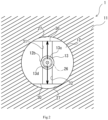
- two communication channels 31, 32 are formed at one end of the guide member 12, as illustrated in Fig. 2 .
- the two communication channels 31, 32 extend in opposite directions along the radius of an inner hole 12a of the guide member 12 and connect the valve port 26 and the gaps 27, 27.
- two communication channels 33, 34 are formed at the other end of the guide member 12, and the gaps 27, 27 and the inner hole 12a of the guide member 12 are connected by communication channels 33, 34. Furthermore, the main valve body 13 is inserted into the inner hole 12a, as illustrated in Fig. 3 .
- the main valve body 13 is formed in the approximate shape of a circular cylinder having a closed end with a base end portion 13b larger in diameter than a leading end portion 13a.
- the base end portion 13b of the main valve body 13 shaped as just described fits into the inner hole 12a and can move axially along the inner hole 12a of the guide member 12.
- the main valve body 13 can be in a closed position such as that illustrated in Fig. 1 and includes a seat member 13c on a leading end surface.
- the seat member 13c is seated on a valve seat 28, and thus the valve port 26 is closed.
- the main valve body 13 is positioned in an open position by moving axially in the opposite direction, the seat member 13c separates from the valve seat 28, and thus the valve port 26 is opened.
- the main valve body 13 configured as described above forms a housing space 35 with the guide member 12 in order to house a first coil spring 16.
- the inner hole 12a has one end portion 12b formed smaller in diameter than a remaining portion 12c, and the leading end portion 13a of the main valve body 13 is inserted through the one end portion 12b.
- the housing space 35 in the approximate shape of a circular ring is formed between the leading end portion 13a of the main valve body 13 and the guide member 12, and the first coil spring 16 is housed in the housing space 35.
- the first coil spring 16 is what is called a compression coil spring and provides, to the main valve body 13, a biasing force in an opening direction from the closed position to the open position.
- the first coil spring 16 can be replaced by a leaf spring, an elastic body, a magnetic spring, a pneumatic spring, a pressing mechanism that uses an electrostatic force, or the like.
- a pilot passage 13d is formed to allow communication between the first port 22 and the second port 24 when the main valve body 13 is in the closed position.
- the pilot passage 13d passes through the main valve body 13 along the axial line thereof, and when the main valve body 13 is seated, connects the valve port 26 and an inner hole 13e of the main valve body 13.
- the seat piston 14 is inserted through the inner hole 13e of the main valve body 13 in such a manner as to be axially movable and located adjacent to the housing space 35.
- the seat piston 14 is formed in the approximate shape of a circular column, and closes the pilot passage 13d by inserting a leading end 14a of the seat piston 14 into a seat portion 13f of the pilot passage 13d and causing the leading end 14a to be seated.
- the pilot passage 13d is closed.
- the seat piston 14 can move from the pilot closed position to a pilot open position along the axial line of the seat position 14, and when the seat piston 14 moves, the leading end 14a separates from the seat portion 13f. Accordingly, the pilot passage 13d is opened, and the valve port 26 and the inner hole 13e of the main valve body 13e are brought into communication.
- a plurality of slits (in the present embodiments, two slits) 14b, 14b are formed in the outer peripheral surface of the seat piston 14, and the slits 14b, 14b form channels connecting the pilot passage 13d and the aforementioned two communication channels 33, 34 when the pilot passage 13d is open.
- the seat piston 14 configured as just described has a base end portion 14c protruding from the main valve body 13, and the electromagnetic drive device 15 is provided on this protrusion.
- the electromagnetic drive device 15 includes a plunger 41, a stationary pole 42, and a solenoid 43.
- the plunger 41 is a member in the approximate shape of a circular cylinder that is made of a magnetic material, and the base end portion 14c of the seat piston 14 is inserted through an inner hole 41a of the plunger 41. Furthermore, in the inner hole 41a, a leading end portion 41b is formed smaller in diameter than the base end portion 41c, and accordingly a base end 14d of the seat piston 14 is formed larger in diameter than the remaining portion.
- the plunger 41 engages the base end 14d of the seat piston 14 at the leading end portion of the inner hole 41a of the plunger 41 and is configured to move in conjunction with the seat piston 14.
- the stationary pole 42 is provided so as to face the plunger 41 configured as just described.
- the stationary pole 42 is a member in the approximate shape of a circular column that is made of a ferromagnetic material and is disposed apart from the base end of the plunger 41 in one axial direction.
- the outer diameter of a leading end portion 42b of the stationary pole 42 disposed as just described is approximately equal to the outer diameter of the plunger 41, and a sleeve 44 is provided surrounding the leading end portion 42b of the stationary pole 42 and the plunger 41.
- the sleeve 44 is a member in the approximate shape of a circular cylinder that is made of a non-magnetic material and is configured so that the plunger 41 can move axially in the sleeve 44.
- the solenoid 43 is provided surrounding the sleeve 44 configured as just described.
- the second coil spring 17, which is one example of the basing member, is what is called a compression coil spring and is inserted through the plunger 41.
- the inner hole 41a of the plunger 41 forms a spring housing chamber 45 together with a spring bearing recess 42a of the stationary pole 42 to be described later, and the second coil spring 17 is housed in the spring housing chamber 45.
- the second coil spring 17 has one end fitted into the spring bearing recess 42a of the stationary pole 42 and the other end pressed against the base end 14d of the seat piston 14. Therefore, the second coil spring 17 biases the plunger 41 via the seat piston 14 in one axial direction and pulls the plunger 41 away from the stationary pole 42.
- the second coil spring 17 enables the plunger 41 and the seat piston 14 to move in conjunction with each other, and positions the seat piston 14 in the pilot closed position in the state where no electric current flows through the solenoid 43. Moreover, the second coil spring 17 provides a biasing force acting in a closing direction from the open position to the closed position to the seat piston 14 via the main valve body 13 and positions the main valve body 13 in the closed position. Note that the second coil spring 17 can be replaced by a leaf spring, an elastic body, a magnetic spring, a pneumatic spring, a pressing mechanism that uses an electrostatic force, or the like.
- the outer peripheral surface of the solenoid 43 is formed larger in diameter at the base end than at the remaining portion, and an annular channel 29 in the shape of a circular ring is formed between the remaining portion and the housing 11.
- the annular channel 29 is connected to the second port 24 via the second channel 25, is connected to the first port 22 via the gaps 27, 27, the communication channels 31, 32, and the first channel 23, and forms a valve passage 30 together with these channels 23, 25, 27, 27, 31, 32.
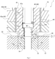
- This gap 48 is formed so as to have a width S between 0.01 mm and 0.5 mm, inclusive, in order to limit the amount of gas to be introduced into and discharged from the spring housing chamber 45. With this, abrupt changes in the volume of the spring housing chamber 45 are minimized, and the spring housing chamber 45 has a damping function, in other words, the spring housing chamber 45 plays the role of the damping chamber 46.
- the gas solenoid valve 1 is provided on the gas tank and can cause the gas to flow in both directions in the valve passage 30 in order to fill the gas tank with the gas and discharge the gas from the gas tank, for example.
- an electric current flows to the coil 43b of the solenoid 43. Therefore, the plunger 41 is lifted up, and the seat piston 14 moves to the pilot open position accordingly.
- the pilot passage 13d is opened, and the gas is guided to the first channel 23 through the two communication channels 33, 34, the slits 14b, 14b, and the pilot passage 13d.
- a damping passage 49 may be formed as can be seen in an alternative unclaimed gas solenoid valve 1A illustrated in Fig. 6 .
- the damping passage 49 is formed through the stationary pole 42 and the lid body 18 in order to connect the damping chamber 46 to the outside, and gas is introduced into and discharged from the damping chamber 46 through the damping passage 49.
- the diameter of the damping passage 49 it is possible to adjust the amount of gas to be introduced and discharged, and the damping force of the damping chamber 46 can be adjusted accordingly.
- the gas solenoid valve 1A has substantially the same configuration as the gas solenoid valve 1 except the damping passage 49; in Fig. 6 , the same elements share the same reference signs.
- the seat piston 14 is provided, but is not necessarily required in other unclaimed examples; the gas solenoid valve may instead be configured in such examples so that the plunger 41 is directly pressed against the main valve body 13. Furthermore, as can be seen in a gas solenoid valve 1B illustrated in Fig. 7 , a seat piston 14B and a main valve body 13B may be configured to move in conjunction using a pin 50.
Landscapes
- Engineering & Computer Science (AREA)
- General Engineering & Computer Science (AREA)
- Mechanical Engineering (AREA)
- Physics & Mathematics (AREA)
- Fluid Mechanics (AREA)
- Magnetically Actuated Valves (AREA)
Claims (2)
- Gasmagnetventil, umfassend:ein Gehäuse (11), einschließlich eines ersten Anschlusses (22), eines zweiten Anschlusses (24) und eines Ventilanschlusses (26), der zu dem ersten Anschluss (22) und dem zweiten Anschluss (24) führt;einen Hauptventilkörper (13), der in der Lage ist, sich zwischen einer geschlossenen Position und einer offenen Position zu bewegen, und konfiguriert ist, um sich durch den Druck von Gas, das über den ersten Anschluss zugeführt wird, in eine Öffnungsrichtung zu bewegen, wobei die geschlossene Position eine Position des Hauptventilkörpers ist, die den Ventilanschluss schließt, wobei die offene Position eine Position des Hauptventilkörpers ist, die den Ventilanschluss öffnet;ein Vorspannelement (17), das eine Vorspannkraft auf den Hauptventilkörper ausübt, um den Hauptventilkörper in der geschlossenen Position zu positionieren, wobei die Vorspannkraft in einer Schließrichtung von der offenen Position in die geschlossene Position wirkt;einen Sitzkolben (14), der über den Hauptventilkörper eingesetzt ist, der die Vorspannkraft des Vorspannelements aufnimmt und den Hauptventilkörper in die geschlossene Position vorspannt; undeine elektromagnetische Antriebsvorrichtung (15), die eine Erregungskraft erzeugt, um den Hauptventilkörper zu veranlassen, sich in die offene Position zu bewegen, wobei die Erregungskraft der Vorspannkraft des Vorspannelements entgegenwirkt, wobei:ein Vorsteuerdurchgang (13d), der den ersten Anschluss und den zweiten Anschluss verbindet, in dem Hauptventilkörper ausgebildet ist;der Sitzkolben in der Lage ist, sich zwischen einer geschlossenen Vorsteuerposition und einer offenen Vorsteuerposition zu bewegen, wobei die geschlossene Vorsteuerposition eine Position des Sitzkolbens ist, die den Vorsteuerdurchgang schließt, und die offene Vorsteuerposition eine Position des Sitzkolbens ist, die den Vorsteuerdurchgang öffnet;die elektromagnetische Antriebsvorrichtung einen Stößel (41) einschließt, durch den der Sitzkolben in einer Weise eingeführt ist, dass er in Verbindung beweglich ist, einen stationären Pol (42), der gegenüber dem Stößel angeordnet ist, und einen Elektromagneten (43), der die Erregerkraft für den Stößel bereitstellt, um den Stößel an den stationären Pol anzuziehen, um den Sitzkolben in die offenen Vorsteuerposition zu bewegen und den Hauptventilkörper in die offene Position zu bewegen;eine Dämpfungskammer (46), die die Bewegung des Hauptventilkörpers dämpft, in dem Stößel ausgebildet ist, um das Vorspannelement zwischen dem Sitzkolben und dem stationären Pol zu positionieren;die Dämpfungskammer an einer Position ausgebildet ist, die in Öffnungsrichtung von dem Sitzkolben entfernt und benachbart zu dem Sitzkolben liegt;das Vorspannelement in der Dämpfungskammer angeordnet ist; undGas durch einen Spalt (48) zwischen dem Sitzkolben und dem Stößel in die Dämpfungskammer eingeleitet und aus ihr abgeleitet wird.
- Gasmagnetventil nach Anspruch 1, ferner umfassend:
einen Anschlag (47), der die Bewegung des Hauptventilkörpers in Öffnungsrichtung begrenzt.
Applications Claiming Priority (2)
| Application Number | Priority Date | Filing Date | Title |
|---|---|---|---|
| JP2019015886A JP7175208B2 (ja) | 2019-01-31 | 2019-01-31 | ガス用電磁弁 |
| PCT/JP2020/002970 WO2020158729A1 (ja) | 2019-01-31 | 2020-01-28 | ガス用電磁弁 |
Publications (3)
| Publication Number | Publication Date |
|---|---|
| EP3919795A1 EP3919795A1 (de) | 2021-12-08 |
| EP3919795A4 EP3919795A4 (de) | 2022-12-21 |
| EP3919795B1 true EP3919795B1 (de) | 2025-04-09 |
Family
ID=71841371
Family Applications (1)
| Application Number | Title | Priority Date | Filing Date |
|---|---|---|---|
| EP20748845.3A Active EP3919795B1 (de) | 2019-01-31 | 2020-01-28 | Elektromagnetisches gasventil |
Country Status (6)
| Country | Link |
|---|---|
| US (1) | US11754197B2 (de) |
| EP (1) | EP3919795B1 (de) |
| JP (1) | JP7175208B2 (de) |
| KR (1) | KR102518266B1 (de) |
| CN (1) | CN113302425B (de) |
| WO (1) | WO2020158729A1 (de) |
Families Citing this family (4)
| Publication number | Priority date | Publication date | Assignee | Title |
|---|---|---|---|---|
| JP7523249B2 (ja) * | 2020-04-27 | 2024-07-26 | 川崎重工業株式会社 | 弁装置 |
| CN214093242U (zh) * | 2020-11-24 | 2021-08-31 | 浙江三花汽车零部件有限公司 | 一种电磁阀 |
| JP2023032234A (ja) * | 2021-08-26 | 2023-03-09 | 仁科工業株式会社 | リリーフ弁 |
| JP7733685B2 (ja) * | 2023-02-13 | 2025-09-03 | 仁科工業株式会社 | 電磁比例リリーフ弁 |
Family Cites Families (28)
| Publication number | Priority date | Publication date | Assignee | Title |
|---|---|---|---|---|
| US3100103A (en) | 1959-06-19 | 1963-08-06 | Robinson D Bullard | Electro-magnetically actuated pilot and main valve |
| JPS5973678A (ja) * | 1982-10-15 | 1984-04-25 | Nichiden Kogyo Kk | 電磁弁 |
| US5048790A (en) * | 1990-07-18 | 1991-09-17 | Target Rock Corporation | Self-modulating control valve for high-pressure fluid flow |
| JPH0735874U (ja) * | 1993-12-10 | 1995-07-04 | 株式会社不二工機製作所 | 電磁弁 |
| WO1996015926A1 (de) * | 1994-11-24 | 1996-05-30 | Robert Bosch Gmbh | Elektromagnetisch steuerbare ventilanordnung |
| DE19501683C2 (de) * | 1995-01-20 | 1998-10-29 | Rexroth Mannesmann Gmbh | Vorgesteuertes Proportional-Druckbegrenzungsventil |
| JPH09294049A (ja) * | 1996-04-25 | 1997-11-11 | Meidensha Corp | 弾性表面波フィルタ |
| JPH09292049A (ja) * | 1996-04-25 | 1997-11-11 | Fuji Koki:Kk | 電磁弁 |
| DE29706717U1 (de) * | 1997-04-14 | 1997-07-17 | Bürkert Werke GmbH & Co., 74653 Ingelfingen | Breitbandventil |
| JPH11132354A (ja) * | 1997-08-27 | 1999-05-21 | Denso Corp | 多段切換電磁弁 |
| JPH11180295A (ja) * | 1997-12-22 | 1999-07-06 | Denso Corp | 電磁弁及びその電磁弁を備えたブレーキ制御装置 |
| JPH11218257A (ja) * | 1998-01-30 | 1999-08-10 | Denso Corp | 電磁弁及びその電磁弁を備えたブレーキ制御装置 |
| DE19855667A1 (de) | 1997-12-05 | 1999-08-26 | Denso Corp | Magnetventil und Bremssystem mit einem Magnetventil |
| JP2001146974A (ja) * | 1999-11-22 | 2001-05-29 | Fuji Koki Corp | 電磁弁 |
| JP3957956B2 (ja) * | 2000-07-19 | 2007-08-15 | 株式会社テージーケー | 二段パイロット式電磁弁 |
| JP2003222261A (ja) | 2002-01-31 | 2003-08-08 | Fuji Koki Corp | 電磁弁 |
| JP5498269B2 (ja) * | 2010-06-15 | 2014-05-21 | 川崎重工業株式会社 | 電磁式開閉弁 |
| DE102010038900B4 (de) * | 2010-08-04 | 2025-02-13 | Robert Bosch Gmbh | Magnetventil sowie Fahrerassistenzeinrichtung |
| WO2012017665A1 (ja) * | 2010-08-06 | 2012-02-09 | 川崎重工業株式会社 | 燃料電池システムの水素ガス供給装置 |
| JP2013057363A (ja) * | 2011-09-08 | 2013-03-28 | Shimadzu Corp | 流体制御弁 |
| JP5733581B2 (ja) * | 2012-11-27 | 2015-06-10 | 株式会社デンソー | 高圧流体用電磁弁装置 |
| JP6093587B2 (ja) * | 2013-02-15 | 2017-03-08 | Kyb株式会社 | ソレノイドバルブ |
| JP5873451B2 (ja) * | 2013-02-26 | 2016-03-01 | 川崎重工業株式会社 | 弁装置 |
| JP6024594B2 (ja) * | 2013-05-23 | 2016-11-16 | トヨタ自動車株式会社 | 電磁弁 |
| JP6142183B2 (ja) * | 2013-06-05 | 2017-06-07 | 株式会社テージーケー | 電磁弁 |
| JP6305769B2 (ja) * | 2014-01-15 | 2018-04-04 | 株式会社ジェイテクト | 弁装置 |
| JP6490382B2 (ja) * | 2014-10-10 | 2019-03-27 | 株式会社ジェイテクト | 弁装置 |
| KR101893361B1 (ko) * | 2016-10-04 | 2018-09-04 | 주식회사 유니크 | 연료 차단 밸브 |
-
2019
- 2019-01-31 JP JP2019015886A patent/JP7175208B2/ja active Active
-
2020
- 2020-01-28 CN CN202080011171.8A patent/CN113302425B/zh active Active
- 2020-01-28 EP EP20748845.3A patent/EP3919795B1/de active Active
- 2020-01-28 WO PCT/JP2020/002970 patent/WO2020158729A1/ja not_active Ceased
- 2020-01-28 US US17/426,415 patent/US11754197B2/en active Active
- 2020-01-28 KR KR1020217021233A patent/KR102518266B1/ko active Active
Also Published As
| Publication number | Publication date |
|---|---|
| WO2020158729A1 (ja) | 2020-08-06 |
| US11754197B2 (en) | 2023-09-12 |
| CN113302425B (zh) | 2023-07-04 |
| JP7175208B2 (ja) | 2022-11-18 |
| EP3919795A1 (de) | 2021-12-08 |
| EP3919795A4 (de) | 2022-12-21 |
| CN113302425A (zh) | 2021-08-24 |
| US20220099210A1 (en) | 2022-03-31 |
| KR20210096264A (ko) | 2021-08-04 |
| JP2020122548A (ja) | 2020-08-13 |
| KR102518266B1 (ko) | 2023-04-06 |
Similar Documents
| Publication | Publication Date | Title |
|---|---|---|
| US11821539B2 (en) | Gas solenoid valve | |
| EP3919795B1 (de) | Elektromagnetisches gasventil | |
| US7959129B2 (en) | Two-port solenoid valve | |
| US20160208954A1 (en) | Valve device | |
| US7523763B2 (en) | Three-port electromagnetic valve | |
| EP3835578B1 (de) | Kapazitätssteuerungsventil | |
| JP3662159B2 (ja) | ソレノイド駆動パイロット弁 | |
| CN102834656B (zh) | 平衡提升型电磁阀 | |
| CN104024709B (zh) | 电磁式线性阀 | |
| US6691740B2 (en) | Self-holding type solenoid-operated valve | |
| US9062778B2 (en) | Valve having a diaphragm capable of displacement within a retaining member | |
| CN112747130A (zh) | 一种燃气阀 | |
| CN112747162B (zh) | 一种燃气比例阀 | |
| US20180355993A1 (en) | Hydraulic valve configuration for nh vbs with a nl solenoid | |
| WO2016035594A1 (ja) | ソレノイド及びソレノイドバルブ | |
| KR100840770B1 (ko) | 솔레노이드밸브 | |
| CN113302424B (zh) | 气体用电磁阀 | |
| CN115492934A (zh) | 阀组件 | |
| CN112747161B (zh) | 一种燃气比例阀 | |
| JP2025155231A (ja) | 塗料用開閉弁 | |
| KR20110005955U (ko) | 직동형 전자 밸브 | |
| JP2006250315A (ja) | 電磁弁 | |
| JP2016136036A (ja) | ソレノイドバルブ |
Legal Events
| Date | Code | Title | Description |
|---|---|---|---|
| STAA | Information on the status of an ep patent application or granted ep patent |
Free format text: STATUS: THE INTERNATIONAL PUBLICATION HAS BEEN MADE |
|
| PUAI | Public reference made under article 153(3) epc to a published international application that has entered the european phase |
Free format text: ORIGINAL CODE: 0009012 |
|
| STAA | Information on the status of an ep patent application or granted ep patent |
Free format text: STATUS: REQUEST FOR EXAMINATION WAS MADE |
|
| 17P | Request for examination filed |
Effective date: 20210831 |
|
| AK | Designated contracting states |
Kind code of ref document: A1 Designated state(s): AL AT BE BG CH CY CZ DE DK EE ES FI FR GB GR HR HU IE IS IT LI LT LU LV MC MK MT NL NO PL PT RO RS SE SI SK SM TR |
|
| DAV | Request for validation of the european patent (deleted) | ||
| DAX | Request for extension of the european patent (deleted) | ||
| A4 | Supplementary search report drawn up and despatched |
Effective date: 20221118 |
|
| RIC1 | Information provided on ipc code assigned before grant |
Ipc: F16K 31/42 20060101ALI20221114BHEP Ipc: F16K 31/122 20060101ALI20221114BHEP Ipc: F16K 1/30 20060101ALI20221114BHEP Ipc: F16K 31/40 20060101ALI20221114BHEP Ipc: F16K 47/02 20060101ALI20221114BHEP Ipc: F16K 31/06 20060101AFI20221114BHEP |
|
| GRAP | Despatch of communication of intention to grant a patent |
Free format text: ORIGINAL CODE: EPIDOSNIGR1 |
|
| STAA | Information on the status of an ep patent application or granted ep patent |
Free format text: STATUS: GRANT OF PATENT IS INTENDED |
|
| RIC1 | Information provided on ipc code assigned before grant |
Ipc: F16K 31/42 20060101ALI20241018BHEP Ipc: F16K 31/122 20060101ALI20241018BHEP Ipc: F16K 1/30 20060101ALI20241018BHEP Ipc: F16K 31/40 20060101ALI20241018BHEP Ipc: F16K 47/02 20060101ALI20241018BHEP Ipc: F16K 31/06 20060101AFI20241018BHEP |
|
| INTG | Intention to grant announced |
Effective date: 20241031 |
|
| GRAS | Grant fee paid |
Free format text: ORIGINAL CODE: EPIDOSNIGR3 |
|
| GRAA | (expected) grant |
Free format text: ORIGINAL CODE: 0009210 |
|
| STAA | Information on the status of an ep patent application or granted ep patent |
Free format text: STATUS: THE PATENT HAS BEEN GRANTED |
|
| AK | Designated contracting states |
Kind code of ref document: B1 Designated state(s): AL AT BE BG CH CY CZ DE DK EE ES FI FR GB GR HR HU IE IS IT LI LT LU LV MC MK MT NL NO PL PT RO RS SE SI SK SM TR |
|
| REG | Reference to a national code |
Ref country code: GB Ref legal event code: FG4D |
|
| REG | Reference to a national code |
Ref country code: CH Ref legal event code: EP |
|
| REG | Reference to a national code |
Ref country code: DE Ref legal event code: R096 Ref document number: 602020049112 Country of ref document: DE |
|
| REG | Reference to a national code |
Ref country code: IE Ref legal event code: FG4D |
|
| REG | Reference to a national code |
Ref country code: NL Ref legal event code: MP Effective date: 20250409 |
|
| PG25 | Lapsed in a contracting state [announced via postgrant information from national office to epo] |
Ref country code: NL Free format text: LAPSE BECAUSE OF FAILURE TO SUBMIT A TRANSLATION OF THE DESCRIPTION OR TO PAY THE FEE WITHIN THE PRESCRIBED TIME-LIMIT Effective date: 20250409 |
|
| REG | Reference to a national code |
Ref country code: AT Ref legal event code: MK05 Ref document number: 1783770 Country of ref document: AT Kind code of ref document: T Effective date: 20250409 |
|
| PG25 | Lapsed in a contracting state [announced via postgrant information from national office to epo] |
Ref country code: ES Free format text: LAPSE BECAUSE OF FAILURE TO SUBMIT A TRANSLATION OF THE DESCRIPTION OR TO PAY THE FEE WITHIN THE PRESCRIBED TIME-LIMIT Effective date: 20250409 Ref country code: PT Free format text: LAPSE BECAUSE OF FAILURE TO SUBMIT A TRANSLATION OF THE DESCRIPTION OR TO PAY THE FEE WITHIN THE PRESCRIBED TIME-LIMIT Effective date: 20250811 Ref country code: FI Free format text: LAPSE BECAUSE OF FAILURE TO SUBMIT A TRANSLATION OF THE DESCRIPTION OR TO PAY THE FEE WITHIN THE PRESCRIBED TIME-LIMIT Effective date: 20250409 |
|
| REG | Reference to a national code |
Ref country code: LT Ref legal event code: MG9D |
|
| PG25 | Lapsed in a contracting state [announced via postgrant information from national office to epo] |
Ref country code: NO Free format text: LAPSE BECAUSE OF FAILURE TO SUBMIT A TRANSLATION OF THE DESCRIPTION OR TO PAY THE FEE WITHIN THE PRESCRIBED TIME-LIMIT Effective date: 20250709 Ref country code: GR Free format text: LAPSE BECAUSE OF FAILURE TO SUBMIT A TRANSLATION OF THE DESCRIPTION OR TO PAY THE FEE WITHIN THE PRESCRIBED TIME-LIMIT Effective date: 20250710 |
|
| PG25 | Lapsed in a contracting state [announced via postgrant information from national office to epo] |
Ref country code: PL Free format text: LAPSE BECAUSE OF FAILURE TO SUBMIT A TRANSLATION OF THE DESCRIPTION OR TO PAY THE FEE WITHIN THE PRESCRIBED TIME-LIMIT Effective date: 20250409 |
|
| PG25 | Lapsed in a contracting state [announced via postgrant information from national office to epo] |
Ref country code: BG Free format text: LAPSE BECAUSE OF FAILURE TO SUBMIT A TRANSLATION OF THE DESCRIPTION OR TO PAY THE FEE WITHIN THE PRESCRIBED TIME-LIMIT Effective date: 20250409 |
|
| PG25 | Lapsed in a contracting state [announced via postgrant information from national office to epo] |
Ref country code: HR Free format text: LAPSE BECAUSE OF FAILURE TO SUBMIT A TRANSLATION OF THE DESCRIPTION OR TO PAY THE FEE WITHIN THE PRESCRIBED TIME-LIMIT Effective date: 20250409 |
|
| PG25 | Lapsed in a contracting state [announced via postgrant information from national office to epo] |
Ref country code: AT Free format text: LAPSE BECAUSE OF FAILURE TO SUBMIT A TRANSLATION OF THE DESCRIPTION OR TO PAY THE FEE WITHIN THE PRESCRIBED TIME-LIMIT Effective date: 20250409 |
|
| PG25 | Lapsed in a contracting state [announced via postgrant information from national office to epo] |
Ref country code: RS Free format text: LAPSE BECAUSE OF FAILURE TO SUBMIT A TRANSLATION OF THE DESCRIPTION OR TO PAY THE FEE WITHIN THE PRESCRIBED TIME-LIMIT Effective date: 20250709 |
|
| PG25 | Lapsed in a contracting state [announced via postgrant information from national office to epo] |
Ref country code: IS Free format text: LAPSE BECAUSE OF FAILURE TO SUBMIT A TRANSLATION OF THE DESCRIPTION OR TO PAY THE FEE WITHIN THE PRESCRIBED TIME-LIMIT Effective date: 20250809 |
|
| PG25 | Lapsed in a contracting state [announced via postgrant information from national office to epo] |
Ref country code: LV Free format text: LAPSE BECAUSE OF FAILURE TO SUBMIT A TRANSLATION OF THE DESCRIPTION OR TO PAY THE FEE WITHIN THE PRESCRIBED TIME-LIMIT Effective date: 20250409 |
|
| REG | Reference to a national code |
Ref country code: DE Ref legal event code: R097 Ref document number: 602020049112 Country of ref document: DE |
|
| PG25 | Lapsed in a contracting state [announced via postgrant information from national office to epo] |
Ref country code: SM Free format text: LAPSE BECAUSE OF FAILURE TO SUBMIT A TRANSLATION OF THE DESCRIPTION OR TO PAY THE FEE WITHIN THE PRESCRIBED TIME-LIMIT Effective date: 20250409 Ref country code: DK Free format text: LAPSE BECAUSE OF FAILURE TO SUBMIT A TRANSLATION OF THE DESCRIPTION OR TO PAY THE FEE WITHIN THE PRESCRIBED TIME-LIMIT Effective date: 20250409 |
|
| PG25 | Lapsed in a contracting state [announced via postgrant information from national office to epo] |
Ref country code: CZ Free format text: LAPSE BECAUSE OF FAILURE TO SUBMIT A TRANSLATION OF THE DESCRIPTION OR TO PAY THE FEE WITHIN THE PRESCRIBED TIME-LIMIT Effective date: 20250409 |
|
| PG25 | Lapsed in a contracting state [announced via postgrant information from national office to epo] |
Ref country code: EE Free format text: LAPSE BECAUSE OF FAILURE TO SUBMIT A TRANSLATION OF THE DESCRIPTION OR TO PAY THE FEE WITHIN THE PRESCRIBED TIME-LIMIT Effective date: 20250409 |
|
| PG25 | Lapsed in a contracting state [announced via postgrant information from national office to epo] |
Ref country code: RO Free format text: LAPSE BECAUSE OF FAILURE TO SUBMIT A TRANSLATION OF THE DESCRIPTION OR TO PAY THE FEE WITHIN THE PRESCRIBED TIME-LIMIT Effective date: 20250409 Ref country code: SK Free format text: LAPSE BECAUSE OF FAILURE TO SUBMIT A TRANSLATION OF THE DESCRIPTION OR TO PAY THE FEE WITHIN THE PRESCRIBED TIME-LIMIT Effective date: 20250409 |
|
| PG25 | Lapsed in a contracting state [announced via postgrant information from national office to epo] |
Ref country code: IT Free format text: LAPSE BECAUSE OF FAILURE TO SUBMIT A TRANSLATION OF THE DESCRIPTION OR TO PAY THE FEE WITHIN THE PRESCRIBED TIME-LIMIT Effective date: 20250409 |
|
| PLBE | No opposition filed within time limit |
Free format text: ORIGINAL CODE: 0009261 |
|
| STAA | Information on the status of an ep patent application or granted ep patent |
Free format text: STATUS: NO OPPOSITION FILED WITHIN TIME LIMIT |
|
| REG | Reference to a national code |
Ref country code: CH Ref legal event code: L10 Free format text: ST27 STATUS EVENT CODE: U-0-0-L10-L00 (AS PROVIDED BY THE NATIONAL OFFICE) Effective date: 20260218 |
|
| 26N | No opposition filed |
Effective date: 20260112 |